


FMX-24P
USER’S MANUAL
1
PLANEX COMMUNICATIONS INC.
Table of Contents
1. Introduction.................................................................................................................. 2
1.1 Product Overview ......................................................................................................2
1.2 Package Contents ......................................................................................................3
1.3 Part Names ................................................................................................................ 3
2. Quick Installation ........................................................................................................ 5
2.1 Installation Procedure...............................................................................................5
2.2 Cautionary Notes on Selecting Installation Location ..............................................5
2.3 Connecting the Power Cable .....................................................................................6
2.4 Performing Basic Configuration ...............................................................................6
2.5 Connecting Hubs and PC's........................................................................................ 6
3. Managing the Switch ...................................................................................................8
3.1 Serial Port Connection ..............................................................................................8
3.2 Telnet Connection ......................................................................................................9
4. Configuring the Switch .............................................................................................. 10
4.1 Logging into the Switch........................................................................................... 10
4.2 Menu Hierarchy.......................................................................................................10
4.2.1 Configuration ....................................................................................................12
4.2.2 Network Monitoring.......................................................................................... 45
4.2.3 SNMP Manager Configuration......................................................................... 53
4.2.4 User Accounts Management.............................................................................54
4.2.5 System Utilities................................................................................................. 55
4.2.6 Save Changes ....................................................................................................61
4.2.7 Reboot ................................................................................................................ 62
4.2.8 Logout ................................................................................................................ 63
5. Sample Configuration ................................................................................................ 64
5.1 Configuring IP address............................................................................................ 65
5.2 Configuring User Name ..........................................................................................66
5.3 Configuring Spanning Tree.....................................................................................68
5.4 Configuring PoE (Power over Ethernet)................................................................. 71
5.5 Configuring SNMP ..................................................................................................73
5.6 Configuring QoS ......................................................................................................74

FMX-24P
USER’S MANUAL
2
PLANEX COMMUNICATIONS INC.
1. Introduction
1.1 Product Overview
All ports on this product comply with IEEE802.3af (Power over Ethernet) and are
capable of providing power to devices supporting this power supply standard. The
FMX-24P is a rack-mount-sized intelligent switching hub compliant with
IEEE802.3 10BASE-T and IEEE802.3u 100BASE-TX specifications.
The product provides twenty-four RJ-45 STP ports that all support
Auto-Negotiation and MDI/MDI-X
The product supports IEEE802.1Q VLAN, IEEE802.1p Priority Control and
IEEE802.1d Spanning Tree, and provides interconnectivity to hubs from other
vendors that comply with these standards.
The product allows you to manage the attached network through its on-board
functions including SNMP, Telnet and RS-232C console connection. Furthermore,
its built-in RMON-based network monitoring function reduces the burden on your
system administrator as it enables him/her to remotely monitor the
communication status.
[Product Features]
z IEEE802.3af compliant power supply feature provides a total and maximum of
152W for the 24 ports
z Complies with IEEE802.3 10BASE-T and IEEE802.3u 100BASE-TX standards
z Provides twenty-four RJ-45 STP ports supporting 10/100BASE-TX
z Auto-Negotiation function automatically detects speed (10M/100M) and duplex
mode (half/full duplex)
z AutoMDI/MDI-X function automatically detects the straight/crossover cable
type
z Built-in MAC address table automatically learns up to 8,000 MAC addresses
z 8MB packet buffer
z Mountable to standard 19-inch racks
z Compliant with IEEE802.1Q VLAN (255 groups)
z Compliant with IEEE802.1Q/p, enables 4-level priority control
z Supports 1)ToS-to-CoS as well as 2)CoS-to-ToS conversion functions

FMX-24P
USER’S MANUAL
3
PLANEX COMMUNICATIONS INC.
z Compliant with IEEE802.1d Spanning Tree
z Firmware upgrade via a TFTP server
z Supports MAC address filtering
1.2 Package Contents
The product package contains the following items:
z FMX-24P (x1)
z RS-232C crossover cable (D-sub 9pin female/female) for system configuration
z Power cable
z Rackmount metal fittings (x2)
z Rackmount setscrews (x8)
z Rubber footpads (x4)
z This user's manual (CD-ROM)
z Warranty card
If any item is found missing, please contact your local retailer or our technical
support.
1.3 Part Names
Front Panel
1) RJ-45 STP Connector
Each connector represents an RJ-45 port to which a
10BASE-T/100BASE-TX twisted pair cable attaches.
2) Serial Port
The supplied RS-232C cable connects to this D-SUB 9pin (male) serial
port to establish a connection to a PC. The FMX-24P is configured via
the attached PC.
LED Status
[System LED]
These LED's indicate current system status.

FMX-24P
USER’S MANUAL
4
PLANEX COMMUNICATIONS INC.
LED Status Description
Green/
ON
The LED is turned on when the switch connects to
the system configuration/management screen.
Console
OFF The LED is dark when the switch is not connected to
the system configuration/management screen.
Green/
ON
Indicates that power is ON Power
OFF Indicates that power is OFF
[Port LED]
These LED's indicate the operational status of each port.
LED Status Description
Green/
ON
The LED is turned on when there is a 100M link.
Green/
Blinking
The LED flashes during 100M data transfer.
Orange/
ON
The LED is turned on when there is a 10M link.
Orange/
Blinking
The LED flashes during 10M data transfer.
Link/Act
OFF The LED is dark when there is no link on the port.
Green/
ON
The LED is turned on when there is link in full
duplex mode.
FDX
OFF The LED is dark if there is no link on the port or if
there is a link in half-duplex mode.
PoE Green/
ON
The LED is turned on when power is supplied via
Power over Ethernet function.

FMX-24P
USER’S MANUAL
5
PLANEX COMMUNICATIONS INC.
2. Quick Installation
2.1 Installation Procedure
This section describes quick installation steps of the FMX-24P. Please install the
product on a level surface and ensure that there is proper air flow at the
installation location. The switch also needs to be kept away from moisture and
dust.
1. Take the product out of package.
2. Install (place) the product.
3. Connect the supplied power cable to the product.
4. Connect a PC to Console port of the product via the supplied RS-232C cable.
The PC is used to perform basic configuration of the switch.
5. Attach hub(s) and PC(s) to the product.
2.2 Cautionary Notes on Selecting Installation Location
Please strictly follow the instructions below when installing the product.
z Do not install the product in a damp place.
z Avoid exposure to direct sunshine and/or dust.
z Be sure to allow some space between the product and surrounding walls,
etc.
z Do not place any object on the product.
An accumulation of dust or dirt in the air vents near the fan may prevent sufficient
heat dissipation, leading to product malfunction or breakdown. Inspect these
sections of the product once a month and remove any dirt by a vacuum cleaner, etc.
Desktop Installation
Please follow the steps below if you are installing the product on a level surface
(desktop, etc).
1. Attach the supplied rubber footpads on the four corners of the bottom surface
of the product.
2. Place the product on a level surface.

FMX-24P
USER’S MANUAL
6
PLANEX COMMUNICATIONS INC.
[Rack-Mounting]
Follow the steps below to install the product to a standard 19-inch rack. Have a
Phillips head screw driver and the supplied mounting screws (x4) ready.
1) If the supplied rubber footpads have been already attached to the corners
of the bottom face, please remove all of the rubber footpads.
2) Locate the rack-mounting screw holes on the side of the product.
3) Attach the supplied metal rack-mounting fittings to the screw holes.
4) Align the rack-mounting screw holes on the product with the screw holes
on your 19-inch rack, and attach the switch to the rack.
2.3 Connecting the Power Cable
Follow the steps below and firmly attach the supplied power cable to the product.
- Attach the supplied power cable to the connector on the rear side of the
product.
1) Attach the 3-lead plug of the power cable to an outlet with grounding.
2) Installation of the power cable is successful if the Power LED (system
LED) is turned on. (Note that all LED's are turned on immediately after
the product is powered. During self diagnostics, Console LED will flash.
Data transfer/communication starts as soon as Console LED goes off.)
2.4 Performing Basic Configuration
A specific IP address has been assigned to the product prior to its shipment. This
address needs to be changed if you wish to install multiple units of FMX-24P in the
same network. For the method to modify preconfigured IP address, please refer to
Chapter 3.
2.5 Connecting Hubs and PC's
This section describes how to connect a LAN adapter (in your PC) or a network
device (ex. hub, switch) to an RJ-45 connector on the product. Before proceeding,
please obtain a LAN cable that is appropriate for the network speed between the
product and the target network device.
[Supported Network Cables]

FMX-24P
USER’S MANUAL
7
PLANEX COMMUNICATIONS INC.
Since all ports on the product support AutoMDI/MDI-X, both straight-through
and cross-over cables (or connectors with either cable type) may be attached to
the product. (FMX-24P will automatically detect straight/crossover cable type
of the attached network cable.)
1) Attach one end of a LAN cable to the product.
2) Attach the other end of the cable to your hub or network port on your PC.
3) The product automatically detects the best network speed for both the
switch itself and the target device as long as the target device supports
Auto-Negotiation.
4) If only one of the devices is set to Auto-Negotiation (and the speed setting
of the other device is fixed to a certain speed), connection mode is
automatically fixed to half duplex mode.
5) If the target device is set to a specific speed and it's fixed to full duplex
mode, fix the speed/duplex mode of the corresponding port on the
FMX-24P.

FMX-24P
USER’S MANUAL
8
PLANEX COMMUNICATIONS INC.
3. Managing the Switch
The FMX-24P is equipped with a management agent. The management agent
utilizes SNMP to configure and manage the switch. The SNMP agent can be
started via Telnet or a PC attached to the serial port on the management module.
The switch can be managed by any computer on the network as long as both
SNMP agent and SNMP manager are enabled.
SNMP agent provides the following management functions:
z Enable or disable each port
z Modify the communication/connection mode of each port
z Configure SNMP parameters
z Configure VLAN settings
z Configure Spanning Tree settings
z Download system firmware
z Upload and download configuration file
3.1 Serial Port Connection
The switch can be configured and managed via a computer attached to the serial
port on the front panel of the product. Serial port-based configuration utilizes a
VT-100 equivalent terminal utility/program. Windows 95/98/98SE/Me/2000/XP
PC utilizes a communication utility such as HyperTerminal.
*) Macintosh computers may not be attached to the serial port of the product for
configuration purposes.
[Configuring Terminal Utility]
The terminal utility running on the device attached to the serial port of the
product needs to be configured as follows:
Speed: 9600
Parity: None
Data Bit: 8 bit
Stop Bit: 1 bit
Flow Control: None
Windows Terminal Emulator option: None

FMX-24P
USER’S MANUAL
9
PLANEX COMMUNICATIONS INC.
- In the Terminal Preferences screen, enable Function, Arrow and Control keys
[Attaching a Serial Cable]
Verify that your PC is equipped with a D-SUB 9pin male -type serial port. The
connector type of the supplied RS-232C cable is D-SUB 9pin female/female.
Attach one end of the serial cable to the serial port on the front panel of the switch,
and attach the other end of the cable to the serial port on your computer.
3.2 Telnet Connection
The management agent can be started via Telnet as well. The factory default
management IP address of the product is [10, 90, 90, 90/8], and its Telnet interface
has been enabled. The agent can be accessed from a PC that belongs to the same
network address range.

FMX-24P
USER’S MANUAL
10
PLANEX COMMUNICATIONS INC.
4. Configuring the Switch
Both NV-RAM and DRAM are used to store the switch configuration. While the
switch is online, its configuration is saved in DRAM and it accommodates any change
made to the configuration in real time. The contents of DRAM memory are cleared
as soon as the power is turned off. On the other hand, the contents of NV-RAM are
retained after the power-off. When the switch is turned on, the contents of NV-RAM
are duplicated in DRAM memory.
While the switch is being configured, modifications made to the configuration are
first saved in NV-RAM. Then they are written to flash memory to maintain the
same configuration after system power-off.
4.1 Logging into the Switch
The following login screen will appear after logging into the switch. No user
names or passwords are configured prior to product shipment. If this is the first
time you are logging into the switch, it will accept any text string you enter as user
name/password.
To connect to the switch via Telnet, enter your user name and password in the
login screen. If they are not configured yet, enter a new user name and password
that contain at least one alphanumeric character.
4.2 Menu Hierarchy
The management screen of the switch is shown below. For details on each menu
item, please refer to its corresponding subsection.

FMX-24P
USER’S MANUAL
11
PLANEX COMMUNICATIONS INC.
Root Screen
├ Configuration
│ ├ Configure IP Address
│ ├ Configure Switch Information and Advanced Settings
│ ├ Configure Ports
│ ├ Configure Bandwidth
│ ├ Configure Spanning Tree Protocol
│ ├ Configure Static (Destination-Address Filtering) Table
│ ├ Configure VLANs
│ ├ Configure Port Mirroring
│ ├ Configure Threshold of Broadcast/Multicast/DA-Unknown Storm
│ ├ Configure Port Security
│ ├ Configure Class of Service, Default Priority and Traffic Class
│ ├ Configure DIFFSERV Settings
│ └ Configure Power Over Lan Settings
├ Network Monitoring
│ ├ Port Utilization
│ ├ Port Error Packets
│ ├ Port Packet Analysis
│ ├ Browse MAC Address
│ ├ Switch History
│ ├ VLAN Status
│ ├ Port Event Latch
│ └ POL Information
├ SNMP Manager Configuration
├ User Accounts Management
├ System Utilities
├ Save Changes
├ Reboot
└ Logout

FMX-24P
USER’S MANUAL
12
PLANEX COMMUNICATIONS INC.
The following short cut commands can be used at any level in the hierarchy above:
Ctrl + T : Return to the root screen
Esc : Return to the previous level
Ctrl + R : Reload the screen
Tab : Move to the next item/option
Space : Toggle between available options
4.2.1 Configuration
This option is used to configure the switch.
4.2.1.1 Configure IP Address
From the root menu, select [Configuration] - [Configure IP Address] to move to
the screen below.
This option is used to set an IP address to the switch. The FMX-24P is an
intelligent switching hub, and it utilizes this IP address to enable SNMP traps
and Telnet-based remote management.
An IP address must be reconfigured before adding FMX-24P to an existing
network or installing multiple units of FMX-24P in the same network. This
process is necessary to ensure that there is no IP address overlapping.
FMX-24P
USER’S MANUAL
13
PLANEX COMMUNICATIONS INC.
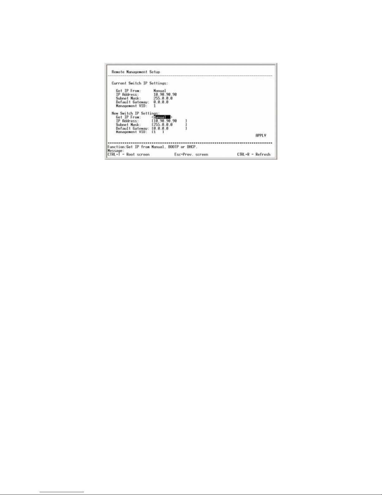
Current Switch IP Settings:
This option displays the information currently configured to the switch. Its
factory default parameters are as follows:
Get IP From: Manual
IP Address: 10.90.90.90
Subnet Mask: 255.0.0.0
Default Gateway: 0.0.0.0
Management VID: 1
1) Get IP From : Indicates how IP address is configured.
Manual : Manually configured
BOOTP : IP address is automatically obtained from BOOTP
DHCP : IP address is automatically obtained via DHCP
Factory default : Manual
2) IP Address : Displays the IP address currently in use
3) Subnet Mask : Displays the subnet mask currently in use
4) Default Gateway : Displays the default route currently in use
5) Management VID : Displays the management VID currently in use
New Switch IP Settings:
This option is used to modify IP address settings.
1) Get IP From:
This option determines how IP address is configured. When BOOTP or
DHCP is selected, the following options will be omitted from the screen

FMX-24P
USER’S MANUAL
14
PLANEX COMMUNICATIONS INC.
2) IP Address
This option is used to set an IP address. To prevent invalid IP configuration,
the following rules have been applied:
1. Class D addresses will be ignored when they are entered.
2. Addresses that end with 0 or 255 are ignored.
3. If a network address and/or broadcast address is entered when a
variable-length subnet mask is in use, the subnet mask setting will
revert to the default value when enabling the new configuration.
3) Subnet Mask
This option is used to configure subnet mask. Should a subnet mask that is
inconsistent with the preconfigured IP address be entered, the default value
is restored upon enabling the new (modified) configuration. Invalid entry
will be ignored, and the factory default is 255.0.0.0.
4) Default Gateway
This option specifies the address of a default route that is used to remotely
configure and manage the switch from a separate network. Enter 0.0.0.0 if
you do not wish to use a default gateway. For this option, the switch will
not check for invalid entries.
5) Management VID
This option defines the management VLAN-ID that is used to configure the
switch. The product can be configured via one management VLAN.
6) APPLY
Use this option to store the current configuration to DRAM. Select APPLY
to modify and update the configuration of the switch that is currently
running.
[Note]
IP address configuration must be performed before adding a network device to a
network. IP address overlapping (two or more devices in the same network
having the same IP address) may result in serious communication failure.

FMX-24P
USER’S MANUAL
15
PLANEX COMMUNICATIONS INC.
4.2.1.2 Configure Switch Information and Advanced Setting
From the root menu, select [Configuration] - [Configure Switch Information and
Advanced Settings] to move to the following screen. This menu is used to
configure system parameters of the product. The menu consists of two levels.
1) Switch Information
This option displays various data of the switch. System name and
location setting for SNMP management can be configured via this option..
2) Configure Advanced Switch Features
The storage time of MAC addresses and other advanced configuration
settings of the system can be configured through this option.
Switch Information:
This option displays product information.
1) Device Type:
Indicates device type
2) MAC Address
Displays the MAC address of the product
3) Boot PROM Version
Displays the boot image version of the product
4) Firmware Version

FMX-24P
USER’S MANUAL
16
PLANEX COMMUNICATIONS INC.
Indicates the product firmware version
5) Base Module Version
Displays the hardware version of the product
6) System Name
Enter an alphanumeric string (256 characters maximum) to specify the
system name of the product.
7) System Location
Enter an alphanumeric string (256 characters maximum) to specify the
system location of the product.
8) System Contact
Enter an alphanumeric string (256 characters maximum) to specify the
system contact of the product.
9) APPLY
Use this option to store the current configuration to DRAM. Select
APPLY to modify and update the configuration of the switch that is
currently running.
10) ADVANCED SETTINGS
Select this option to enable the Advanced configuration mode.
Configure Advanced Switch Features:
This option is used to configure advanced settings of the switch.

FMX-24P
USER’S MANUAL
17
PLANEX COMMUNICATIONS INC.
1) Auto-Logout
After the switch has logged onto the management screen, the product will
automatically log off if there is no key input for the duration specified here.
Available duration options are as follows:
2mins / 5mins / 10mins/ 15mins/ Never
The factory default is 10mins.
2) MAC Address Aging Time (sec):
This option is used to specify the duration for which dynamically learned MAC
addresses are retained. A value between 10 and 1,000,000 sec may be
selected, and the factory default is 300 sec.
*) It is strongly recommended NOT to change this parameter unless there is a
specific reason to do so.
3) Switch GVRP
The product does not support this feature.
4) Telnet Status
Enables or disables Telnet-based remote configuration. The factory default is
"ENABLED".
5) Web Status
The product does not support this feature.
6) Group Address Filter Mode

FMX-24P
USER’S MANUAL
18
PLANEX COMMUNICATIONS INC.
This option determines what action the switch should take upon reception of a
group address. Available options are [Forward All Unregistered], [Filter All
Unregistered] and [Forward All]. The factory default is [Forward All
Unregistered].
7) Scheduling Mechanism for CoS Queues
This option specifies the preferred method to transfer frames that have been
sorted via CoS. Available options are [Strict] and [Round-Robin], and the
factory default is Strict.
*) Select "Strict" if no delay is allowed (ex. IP telephony applications, etc).
8) Backpressure
The product does not support this feature.
9) POL State
Disables or enables the power supply function. The factory default is
"Enabled".
4.2.1.3 Configure Port
From the root menu, select [Configuration] - [Configure Ports] to move to the
following screen. This screen is used to modify port settings.
1) View Ports
Port information of twelve ports is displayed via this option. Select either [1
to 12] or [13 to 24] to view/ configure ports.

FMX-24P
USER’S MANUAL
19
PLANEX COMMUNICATIONS INC.
2) Configure Port From
This option specifies the range of consecutive ports that you wish to configure.
Only the ports within the 12-port group (selected via [View Ports] above) may
be selected.
3) State
This option enables or disables the selected port(s). All ports are enabled
prior to product shipment.
4) Speed/Duplex
This option specifies port speed. Select one of the following options: [Auto],
[100M/Ful], [100M/Half], [10M/Full], [10M/Half]. By default, all ports have
been set to [Auto].
*) If you wish to set a specific speed to any of the ports (fix port speed), please
make sure that the port speed of the target network device is fixed as well.
If a port with automatic speed detection setting is connected to a port with a
fixed speed, half duplex mode is used on the port with auto-speed detect
setting.
*) The FDX LED of the port on the front panel will be turned on if full duplex
mode is selected.
*) If a specific port speed (other than "Auto") has been set to a port, Auto
MDI/MDI-X function is automatically disabled on that port. Should this be
the case, a crossover cable is required to connect the product to another
switch.
5) Flow Control
This function is scheduled to be supported.
6) APPLY
Use this option to save the current configuration to DRAM. Select APPLY to
modify and update the configuration of the switch that is currently running.

FMX-24P
USER’S MANUAL
20
PLANEX COMMUNICATIONS INC.
This screen displays the link speed of each port. Items covered in the screen are
as follows:
1) Port
Displays port number
2) State
Indicates whether or not the use of the port is currently restricted.
3) Settings
Displays port configuration, and its syntax is [Speed/Flow Control Value].
Since the flow control function is not available yet, this item shows
[Speed/Disabled].
4) Connection
Indicates the current link status. Ports with no link are indicated by the
minus ( - ) sign.
4.2.1.4 Configure Bandwidth
From the root menu, select [Configuration] - [Configure Bandwidth] to move to
the following screen. This screen allows the user to specify bandwidth for each
port. This screen/option consists of two levels.
1) Configure Port Ingress Bandwidth
Select this option to open a menu for selecting bandwidth for incoming data

FMX-24P
USER’S MANUAL
21
PLANEX COMMUNICATIONS INC.
(data received by the port).
2) Configure Port Egress Bandwidth
Select this option to open a menu for selecting bandwidth for outgoing data (data
sent by the port).
Configure Port Ingress Bandwidth:
This option specifies bandwidth for data received by the port.
1) Action
Select either [Add/Modify] or [Delete] to add/modify or delete the port specified
in the next option (see below).
2) Port
Enter the port you wish to add/modify or delete.
3) Ingress Bandwidth
Enter a value between 1 and 127 (unit) to specify the actual bandwidth. .
4) APPLY
Use this option to store the current configuration to DRAM. Select APPLY to
modify and update the configuration of the switch that is currently running.
*) 1 unit = 125KB: Although the actual upper limit is 100Mbps for 100 units,

FMX-24P
USER’S MANUAL
22
PLANEX COMMUNICATIONS INC.
the configuration screen displays 127 units (127Mbps).
The screen will reflect the changes made to the existing configuration.
(Example): Controlling bandwidth of 5 units on Port 1
1) Port
Displays the number of port for which new configuration is applied
2) Units
Indicates the number of units that have been configured for the port
3) Kbytes
Converts the number of units to KByte. This is the value that is actually
used in the configuration.
4) Port Speed
Displays the link status of the port being configured. If there is no link, it
will show [none]. If the port speed has been fixed to a certain value, the
corresponding speed will be displayed even if there is no link on the port.
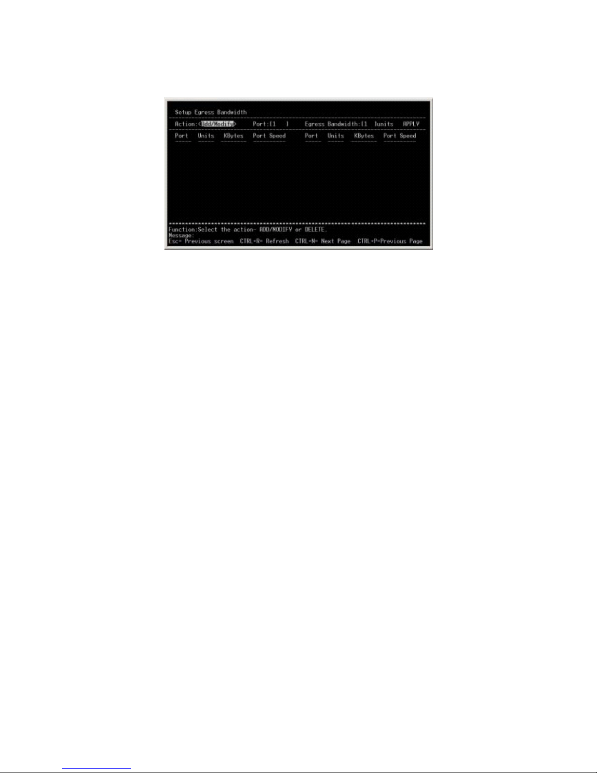
Configure Port Egress Bandwidth:
This option specifies the bandwidth for data sent by a port. It utilizes
basically the same configuration method as [Configure Port Ingress Bandwidth].
FMX-24P
USER’S MANUAL
23
PLANEX COMMUNICATIONS INC.
5) Action
Select either [Add/Modify] or [Delete] to add/modify or delete the port specified
in the next option (see below).
6) Port
Enter the port to add/modify or delete.
7) Ingress Bandwidth
Enter a value between 1 and 127 (unit) to specify the actual bandwidth.
8) APPLY
Use this option to store the current configuration to DRAM. Select APPLY to
modify and update the configuration of the switch that is currently running.
*) 1 unit = 125KB: Although the actual upper limit is 100Mbps for 100 units,
the configuration screen displays 127 units (127Mbps).
Changes made to the existing configuration will be displayed in the screen.
4.2.1.5 Configure Spanning Tree Protocol
From the root menu, select [Configuration] - [Configure Spanning Tree Protocol]
to move to the following screen. This screen is used to configure Spanning Tree
parameters.

FMX-24P
USER’S MANUAL
24
PLANEX COMMUNICATIONS INC.
1) Status
This option enables or disables Spanning Tree. The factory default is
"Disabled".
2) Max Age
Use this option to specify the maximum aging time used in Spanning Tree. A
value between 6 and 40 seconds may be entered, and the factory default is 20
seconds.
3) Hello Time
Use this option to specify the Hello Time (BPDU transmission time) used in
Spanning Tree. A value between 1 and 10 seconds may be entered, and the
factory default is 2 sec.
4) Forward Delay
Use this option to specify the forward delay time used in Spanning Tree. A
value between 4 and 30 seconds may be entered, and the factory default is 15
seconds.
5) Priority
Use this option to specify bridging priority. When combined with the switch's
MAC address, bridging priority becomes "bridge ID". The switching device
with the lowest bridge ID is recognized as the root bridge. A value between 0
and 65535 may be entered, and the factory default is 32768.

FMX-24P
USER’S MANUAL
25
PLANEX COMMUNICATIONS INC.
6) APPLY
Use this option to store the current configuration to DRAM. Select APPLY to
modify and update the configuration of the switch that is currently running.
7) Port Settings
Select this option to move to another mode for configuring Spanning Tree to
ports. This mode is used to display dynamic information of Spanning Tree for
the ports.
[Important]
*) Please note that Spanning Tree (STP) timer settings above should be modified
only by users who have a good understanding of STP technology, or the entire
network may be disabled. The factory default timer settings are the values
most appropriate for networks up to the size of seven lines permitted by IEEE.
Also note that the following STP parameters may not be modified:
- transit delay 1 sec
- bpdu delay 1 sec
- msg overestimate 1 sec
- lost msg (3)
- TX halt delay 1 sec
- Med access delay 0.5 sec
- dia (7)
For detailed information on the options above, please refer to IEEE802.1D. .
Port Settings:
This option is used to modify Spanning Tree setting for each port. Status of
currently effective Spanning tree ports may also be viewed via this option.

FMX-24P
USER’S MANUAL
26
PLANEX COMMUNICATIONS INC.
1) View Ports
Information on twelve ports is displayed via this option. Select either [1 to
12] or [13 to 24] to view or configure ports.
2) Configure Port From
This option specifies the range of consecutive ports that you wish to configure.
3) STP Status
This option is used to enable / disable Spanning Tree function. The factory
default is "Disable".
4) Cost
This option is used to specify port cost. The factory default is 19, and
recommended port cost values are as follows:
100MFDX 19
100MHFX 18
10MFDX 95
10MHFX 100
5) Enter a value between 0 and 255 as port priority. The factory default is 128.
6) ByPass
This option is used when the port is used as fast port. The factory default is
"Disabled". This option must be enabled only when the port (for which

FMX-24P
USER’S MANUAL
27
PLANEX COMMUNICATIONS INC.
ByPass is enabled) is directly connected to a client.
Current configuration and Spanning Tree port status are displayed in the
screen.
1) Port #
Displays port number
2) Connection
Indicates port link status
3) STP Status
Enables or disables the port's Spanning Tree status
4) Cost
Displays the cost assigned to the selected port.
5) Priority
Indicates port priority
6) ByPass
Displays the status of Fast Forward function
7) Port States
Indicates the current Spanning Tree status of the port
- Disabled:
There is no (cable) link on the port
- Listening:
Indicates the Spanning Tree Listening state, and data communication cannot
take place in this state.
- Learning:
Indicates the Spanning Tree Learning state, and data communication cannot
take place in this state..

FMX-24P
USER’S MANUAL
28
PLANEX COMMUNICATIONS INC.
- Forwarding:
Indicates the port through which data communication takes place
- Blocking
The port is currently blocked via Spanning Tree.
4.2.1.6 Configure Static (Destination-Address Filtering) Table
From the root menu, select [Configuration] - [Configure Static
(Destination-Address Filtering) Table] to move to the following screen. This
screen is used to add MAC addresses and configure MAC address filtering. The
screen consists of two levels.
1) Configure Static Unicast Filtering Table
This option is used to manually configure /assign MAC addresses to each port.
2) Configure Static Multicast Filtering Table
This option is used to manually configure/assign multicast addresses to each
port.
Setup Unicast Filtering Table
This option is used to manually assign MAC address to each port.

FMX-24P
USER’S MANUAL
29
PLANEX COMMUNICATIONS INC.
1) ADD/Modify
This option is used to add or delete entries in the MAC address table. Select
[ADD/Modify] to configure entries, or select [Delete] to remove selected
entries.
2) VLAN ID
This option is used to specify VLAN-ID for which MAC addresses are
registered.
3) Type
This option specifies an action associated with the MAC address, VLAN or
port number configured. Select [Permanent] to let the switch learn addresses
statically, or select [Delete on Reset] to filter out the registered address.
4) MAC Address
Enter the MAC address you wish to configure.
5) Allow to Go Port
Enter the number of port you wish to configure.
6) APPLY
Use this option to store the current configuration to DRAM. Select APPLY to
modify and update the configuration of the switch that is currently running.
Changes made to the current configuration will be displayed in the screen.

FMX-24P
USER’S MANUAL
30
PLANEX COMMUNICATIONS INC.
1) Total Entries:
Displays the number of existing entries.
2) MAC Address
Indicates the MAC addresses that have been added so far.
3) VID
Displays the VLAN-ID's that have been configured so far.
4) Port
Indicates the port numbers that have been registered to the switch.
5) Type
Displays the action associated with the registered addresses.
Configure Static Multicast Filtering Table
This option is used to manually associate MAC addresses and multicast MAC
addresses to the switch. The configuration method is the same as [Configure
Static Unicast Filtering Table].
*) You may not dynamically assign/configure learned addresses. Before
configuring this option, be sure to remove all cables from the product.
FMX-24P
USER’S MANUAL
31
PLANEX COMMUNICATIONS INC.
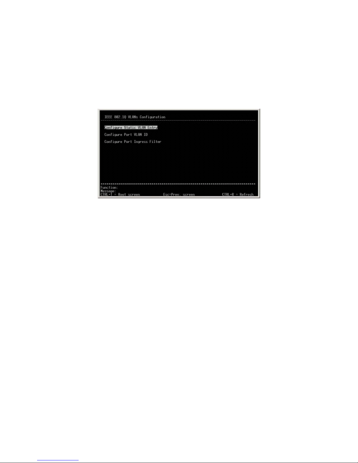
4.2.1.7 Configure VLANs
From the root menu, select [Configuration] - [Configure VLANs] to move to the
following screen. This screen is used to configure VLAN parameters, and it
consists of three levels.
1) Configure Static VLAN Entry
This option is used to add a VLAN group and assign each VLAN group to a
specific port.
2) Configure Port VLAN ID
Use this option to configure the Port-VLAN-ID of each port.
3) Configure Port Ingress Filter
Use this option to enable/disable Ingress Filter of each port.
Configure Static VLAN Entry
This option is used to both create a VLAN group and assign each VLAN group to
a specific port.

FMX-24P
USER’S MANUAL
32
PLANEX COMMUNICATIONS INC.
1) VID
Use this option to specify a VLDN ID to the VLAN group you wish to create
or configure. A value between 2 and 4094 may be entered as VLAN ID.
2) VLAN Name
Enter the name of VLAN you wish to configure. (This step may be skipped.)
3) Egress/Forbidden
Use this option to configure the port that are added to a VLAN group. Use
"E" for ports that are added to a VLAN group. Use "-" for ports that are not
member of the group.
4) Tag/UnTag
This option is used to determine whether Tag transmission or UnTag
transmission is made when a port transmits frames with VLAN information.
Enter "T" for Tag transmission, or "U" to perform UnTag transmission.
5) State
Use this option to configure the status of the VLAN being configured.
6) APPLY
Use this option to store the current configuration to DRAM. Select APPLY
to modify and update the configuration of the switch that is currently
running.
* Prior to product shipment, all ports have been assigned to VLAN-1. VLAN-1

FMX-24P
USER’S MANUAL
33
PLANEX COMMUNICATIONS INC.
may not be deleted, and VLAN-1 information may not be transmitted via Tag.
Configure Port VLAN ID
This option is used to configure PVID (native VLAN) of each port. The numbers
assignable as PVID are selected from the VLAN group to which the port belongs.
1) Configure Port from
Use this option to specify the range of port numbers that you wish to
configure.
2) PVID
Specify a PVID (number) for the port that have been selected via [Configure
Port from].
3) APPLY
Use this option to store the current configuration to DRAM. Select APPLY to
modify and update the configuration of the switch that is currently running.
Configure Port Ingress Filter
Use this option to configure Ingress Filter of each port. If Ingress Filter is
enabled on a port, incoming Untag frames will be destroyed on that port upon
their reception.

FMX-24P
USER’S MANUAL
34
PLANEX COMMUNICATIONS INC.
1) Configure Port from
Use this option to specify the range of port numbers that you wish to
configure.
2) Ingress Filter
Enable or disable Ingress Filter on the ports specified via [Configure Port
from].
3) APPLY
Use this option to store the current configuration to DRAM. Select APPLY to
modify and update the configuration of the switch that is currently running
4.2.1.8 Configure Port Mirroring
From the root menu, select [Configuration] - [Configure Port Mirroring] to move
to the following screen. This screen is used configure port mirroring settings.

FMX-24P
USER’S MANUAL
35
PLANEX COMMUNICATIONS INC.
1) Source Port
Use this option to specify the port from which data is collected via the port
mirroring function.
2) Source Direction
Use this option to specify the transfer mode of incoming/outgoing/incoming +
outgoing data on the port selected in [Source Port] above.
Incoming and Outgoing data: [Ingress & Egress]
Incoming data : [Ingress]
Outgoing data [Egress]
3) Target Port
Use this option to specify the port to which the frames duplicated via
mirroring function are sent (Sniffer port).
4) Mirror Status
Use this option to enable or disable port mirroring.
5) APPLY
Use this option to store the current configuration to DRAM. Select APPLY to
modify and update the configuration of the switch that is currently running.
4.2.1.9 Configure Threshold of Broadcast/Multicast/DA-Unknown Storm
From the root menu, select [Configuration] - [Configure Threshold of
Broadcast/Multicast/DA-Unknown Storm] to move to the following screen. This
screen is used to configure various storm functions.

FMX-24P
USER’S MANUAL
36
PLANEX COMMUNICATIONS INC.
1) Broadcast Storm
Use this option to enable/disable broadcast storm monitoring.
2) Multicast Storm
Use this option to enable/disable multicast storm monitoring.
3) DA-Unknown Storm
Use this option to enable/disable the function for monitoring other storms.
4) Threshold (Pkts/sec)
Use this option to specify the maximum number of packets allowed in one
second for the monitoring function. Enter a value between 0 and 262143.
5) APPLY
Use this option to store the current configuration to DRAM. Select APPLY to
modify and update the configuration of the switch that is currently running.
4.2.1.10 Port Security Settings

FMX-24P
USER’S MANUAL
37
PLANEX COMMUNICATIONS INC.
1) View Ports
Use this option to select the ports you wish to view.
2) Configure Port from
Use this option to specify the range of ports you wish to configure.
3) Admin State
Use this option to enable or disable port security function on the ports
specified via [Configure Port from] above.
4) Max Addr
Use this option to specify the upper limit of the number of MAC addresses
learned by a single port. Enter a value between 0 and 10.
5) Mode
Use this option to specify the method by which MAC addresses are learned.
[DeleteOnReset] Select this option to delete MAC addresses immediately.
[DeleteOnTimeout] Select this option to let the entries be deleted after the
aging time of MAC address table has expired.
APPLY
Use this option to store the current configuration to DRAM. Select APPLY to
modify and update the configuration of the switch that is currently running.

FMX-24P
USER’S MANUAL
38
PLANEX COMMUNICATIONS INC.
4.2.1.11 Configure Class of Service, Default Priority and Traffic Class
From the root menu, select [Configuration] - [Configure Class of Service, Default
Priority and Traffic Class] to move to the following screen. Use this screen to
configure priority control function of the product. The screen consists of three
levels.
1) Configure Class of Service
Use this option to specify latency and the number of packets in packet
transmission queue that is used for the round-robin method.
2) Configure Default Priority
Use this option to specify the CoS value for each port. CoS value is assigned
to frames received that do not include CoS information.
3) Configure Class of Traffic
Based on the CoS value, one of the four Classes (used by the switch) is
assigned.
Configure Class of Service
This option is used to determine the latency and number of packets in the packet
transmission queue which is used for the round-robin method. CoS is configured

FMX-24P
USER’S MANUAL
39
PLANEX COMMUNICATIONS INC.
for each class.
1) Max. Packets
Use this option to specify the number of packets in a packet transmission
queue. The maximum value allowed is 255.
2) Max. Latency
Use this option to specify the duration for which packets received via the
round-robin method are retained (not destroyed). Enter a value between
1 and 255 where 1 equals 16m/sec.
3) APPLY
Use this option to store the current configuration to DRAM. Select
APPLY to modify and update the configuration of the switch that is
currently running.
Configure Default Priority
Use this option to specify the CoS value for each port. CoS is assigned to
incoming frames that do not include any CoS information.

FMX-24P
USER’S MANUAL
40
PLANEX COMMUNICATIONS INC.
1) Configure Port From
Use this option to specify the range of ports you wish to configure.
2) Default Priority
Use this option to specify the CoS value assigned to the ports selected via
[Configure Port From] above.
3) APPLY
Use this option to store the current configuration to DRAM. Select APPLY
to modify and update the configuration of the switch that is currently
running.
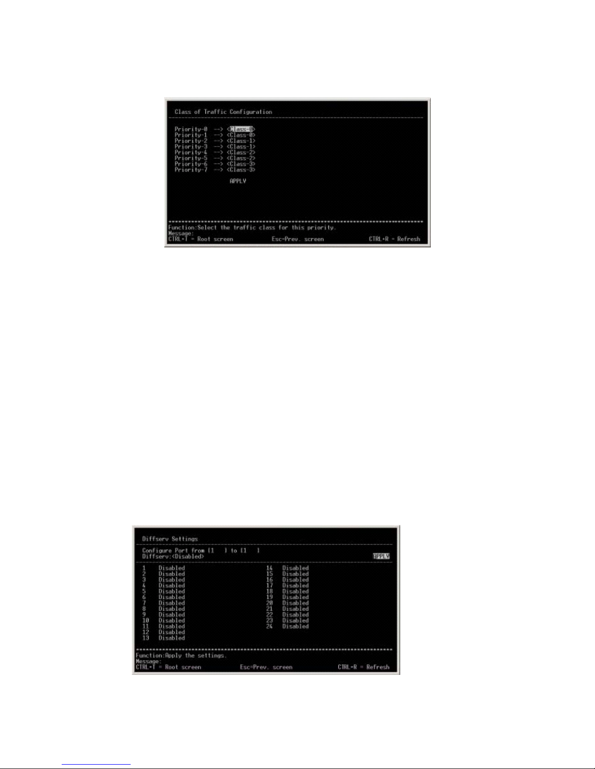
Configure Class of Traffic
Use this option to modify the four class types (used by this product) that are
assigned to CoS values.
FMX-24P
USER’S MANUAL
41
PLANEX COMMUNICATIONS INC.
1) Class - [ ]
Enter the Class number that is assigned to the CoS Priority value shown
on the left.
2) APPLY
Use this option to store the current configuration to DRAM. Select
APPLY to modify and update the configuration of the switch that is
currently running.
4.2.1.12 Configure DIFFSERV Settings
From the root menu, select [Configuration] - [Configure DIFFSERV Settings] to
move to the following screen. This screen is used to configure DIFFSERV
settings.

FMX-24P
USER’S MANUAL
42
PLANEX COMMUNICATIONS INC.
1) Configure Port From
Use this option to specify the range of ports you wish to configure.
2) Diffserv
Use this option to configure Diffserv status.
[Disabled] Diffserv is disabled
[DSCP] DSCP is used
Mode:
[Force Overwrite]
DSCP value is overwritten with the value specified here.
[Change if 0]
The value entered here will be used if DSCP value is zero.
DSCP value:
Enter the DSCP value you wish to configure.
[TOS] : TOS will be used.
Mode:
[Force Overwrite]
TOS value is overwritten with the value entered here.
[TOS Overwrite 802.1p]
TOS priority value is checked and is overwritten with CoS value.
[802.1p Overwrite TOS]
CoS priority value is checked and is overwritten with TOS value.
TOS Value:
Enter the TOS value you wish to configure.
3) APPLY
Use this option to store the current configuration to DRAM. Select APPLY to
modify and update the configuration of the switch that is currently running.

FMX-24P
USER’S MANUAL
43
PLANEX COMMUNICATIONS INC.
4.2.1.13 Configure Power Over LAN Settings
From the root menu, select [Configuration] - [ Configure Power Over Lan
Settings] to move to the following screen. This screen is used to configure
power supply function. The screen consists of two levels.
1) Configure Power Ports
Use this option to enable or disable power supply function on ports.
2) Configure POL Functionality Control
Use this option to enable or disable the power supply function of the product.
Configure Power Ports
Use this option to enable or disable power supply function on each port.

FMX-24P
USER’S MANUAL
44
PLANEX COMMUNICATIONS INC.
1) View Ports
Use this option to specify the port you wish to view.
2) Configure Port from
Use this option to specify the range of ports you wish to configure. Only the
ports that are currently displayed in the screen may be selected (see the port
numbers available).
3) Admin State
Use this option to enable or disable power supply function on the ports
specified via [Configure Port from] above.
4) APPLY
Use this option to store the current configuration to DRAM. Select APPLY to
modify and update the configuration of the switch that is currently running.
Configure POL Functionality Control
This option is used to enable or disable the function to detect a powered device.
IEEE802.3af standard detection method ("Register detection") cannot be
disabled.

FMX-24P
USER’S MANUAL
45
PLANEX COMMUNICATIONS INC.
*) The maximum consumption current of the product conforms to IEEE802.3af
standard.
4.2.2 Network Monitoring
This option is used to display various information of the product.
4.2.2.1 Port Utilization
From the root menu, select [Network Monitoring] - [Port Utilization] to move to
the following screen. This screen is used to display the port utilization status of
the product.

FMX-24P
USER’S MANUAL
46
PLANEX COMMUNICATIONS INC.
1) CLEAR COUNTER
Use this option to clear the port information.
2) Interval
Use this option to configure the interval at which port information is
displayed.
3) Port
Displays port number
4) TX Pkts/sec
Indicates the number of packets sent from the port in PPS
5) RX Pkts/sec
Displays the number of packets received by the port in PPS
6) %Util
Displays the utilization rate of port bandwidth in %. Bandwidth utilization
rate reflects the sum of both transmission and reception of packets.
4.2.2.2 Port Error Packets
From the root menu, select [Network Monitoring] - [Port Error Packets] to move
to the following screen. This screen is used to display the number of error
packets that the product has sent and received.

FMX-24P
USER’S MANUAL
47
PLANEX COMMUNICATIONS INC.
1) Port
Use this option to specify the port number for which you wish to view packet
error information.
2) CLEAR COUNTER
Use this option to clear the counter.
3) Interval
Use this option to specify the interval at which the information is updated.
4.2.2.3 Port Packet Analysis
From the root menu, select [Network Monitoring] - [Port Packet Analysis] to
move to the following screen. This screen displays the number of packets
received and sent by the product.

FMX-24P
USER’S MANUAL
48
PLANEX COMMUNICATIONS INC.
1) Port
Specify the port number for which you wish to view the packet information.
2) CLEAR COUNTER
Use this option to clear the counter.
3) Interval
Use this option to specify the interval at which the information is updated.
4.2.2.4 Browse MAC Address
From the root menu, select [Network Monitoring] - [Browse MAC Address] to
move to the following screen. This screen displays the MAC address table that
stores the MAC addresses learned by the switch.

FMX-24P
USER’S MANUAL
49
PLANEX COMMUNICATIONS INC.
1) Browse By
Use this option to narrow down the displayed items to those that match one of
the following criteria.
[VLAN ID] Select this item to display MAC addresses learned by the specified
VLAN ID.
[MAC Address] Select this item to display the specified MAC addresses.
[ALL] Select this item to display all addresses.
[Port] Select this item to display the MAC addresses learned by the specified
port (number).
4.2.2.5 Switch History
From the root menu, select [Network Monitoring] - [Switch History] to move to
the following screen. This screen is used to display switch history. The
displayed information will be cleared when the switch is turned off or rebooted.
1) Seq
Displays the sequence numbers in switch history
2) Time
Indicates the system up time since last restart

FMX-24P
USER’S MANUAL
50
PLANEX COMMUNICATIONS INC.
3) Log Text
Displays system log
4.2.2.6 VLAN Status
From the root menu, select [Network Monitoring] - [VLAN Status] to move to the
following screen. This screen displays the information of VLANs that have
been configured on the switch. VLAN information for only one VLAN ID is
shown at a time, and VLAN-IDs are displayed in increasing order. Press [Ctrl +
N] to move to the next VLAN ID.
1) Number of IEEE802.1Q VLAN
Indicates the total number of VLAN's currently configured
2) IEEE802.1Q VLAN ID
Displays the VLAN-ID of the VLAN information currently displayed
3) Current Egress Ports
Indicates the ports that belong to this VLAN
4) Current Untagged Ports
Displays the ports whose VLAN-ID have been configured as Untagged
5) Status
Indicates VLAN status

FMX-24P
USER’S MANUAL
51
PLANEX COMMUNICATIONS INC.
6) Creation time since switch power up:
Displays the time that has elapsed since the creation of VLAN group
4.2.2.7 Port Event Latch
From the root menu, select [Network Monitoring] - [Port Event Latch] to move to
the following screen.
4.2.2.8 Power Ports Status
From the root menu, select [Network Monitoring] - [Power Ports Status] to move
to the following screen. This screen is used to view the power supply status of
each port. Power ports status of twelve ports is displayed at one time.

FMX-24P
USER’S MANUAL
52
PLANEX COMMUNICATIONS INC.
1) View Ports
Select this option to specify the number of port you wish to view.
2) Port
Displays port number.
3) Voltage (V)
Indicates the voltage of power ports.
4) Current (mA)
Displays the current of power ports.
5) Power (mW)
Indicates the power consumption of power ports.
6) Status
The data indicates whether or not the power supply function is currently in
use.
7) Cause
Port status is displayed under this item..
[Port admin state is OFF]: The port's PoE status is off
[Under software detection]: The PoE status of the port is ON, but PoE powered
device is not connected
[Legal PD/resistor detection]: Power is being supplied to a PoE powered device
via PoE.
*) The maximum current being supplied on each port conforms to the value(s)
defined in IEEE802.3af.
4.2.2.9 POL Information

FMX-24P
USER’S MANUAL
53
PLANEX COMMUNICATIONS INC.
From the root menu, select [Network Monitoring] - [POL Information] to move to
the following screen. This screen displays the switch-wide POL information.
Please note that the total and maximum power supplied to all ports via POL is
152W or less.
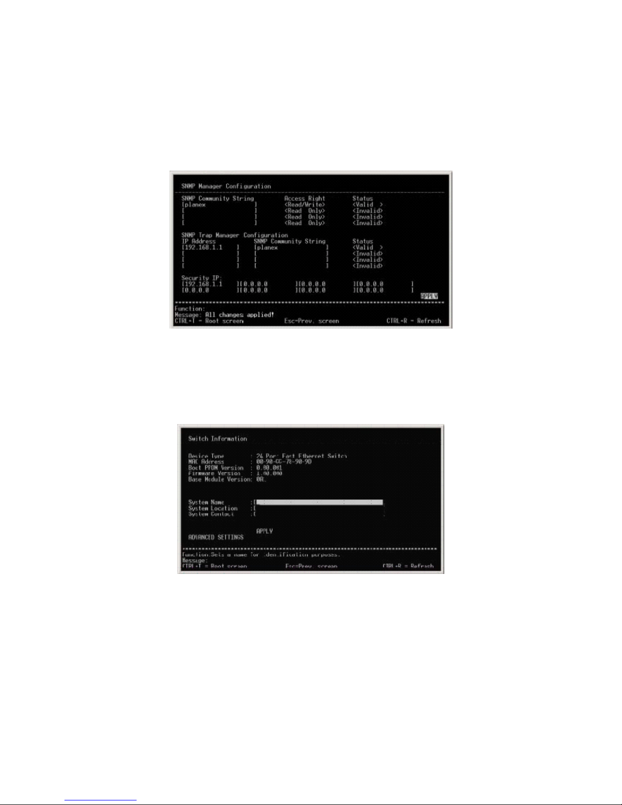
4.2.3 SNMP Manager Configuration
Use this option to configure SNMP parameters.
1) SNMP Community String
Select this option to specify an SNMP community name. Prior to shipment,
two community names ("public", "private") have been already configured. Up
to twenty alphanumeric characters may be used for a community name.

FMX-24P
USER’S MANUAL
54
PLANEX COMMUNICATIONS INC.
2) Access Right
Specify the community's access right to the switch.
3) Status
Use this option to enable or disable the community being configured.
4) SNMP Trap Manager Configuration
Select this option to modify trap settings.
[IP Address] : Enter the IP address to which trap is sent.
[SNMP Community String]: Enter community name.
[Status] Trap transmission may be Enable(d) or Disable(d).
5) Security IP:
Enter the IP address for which SNMP access is permitted. Once an entry is
made, access requests from unregistered addresses will be rejected.
6) APPLY
Use this option to store the current configuration to NV-RAM. Select APPLY
to modify and update the configuration of the switch that is currently
running.
4.2.4 User Accounts Management
Use this option to configure user names and passwords. Up to eight users may
be created. If no user names or passwords are configured, the management
screen may be accessed with any user name /password, or without entering any
user name/password at all. On the other hand, a specific user name and
password are required to access the management screen if you wish to connect to
the switch remotely via Telnet.

FMX-24P
USER’S MANUAL
55
PLANEX COMMUNICATIONS INC.
1) Action
Select this option to create/delete/modify a user name or password.
[ADD] : Creates a user name/password
[Delete] : Deletes an existing user name/password
[Update] : Modifies an existing user name/password
2) Access Level
Select this option to specify the access level of the account being configured.
[Root] : Grants access to all configuration information.
[User+]: : Grants permission to both view configuration and restart the
system.
[User] : Grants permission to view configuration.
At least one user with the Root access needs to be configured at any time.
4.2.5 System Utilities
Select this option to update firmware and export/import system configuration.
Since the product supports TFTP client function, the switch is capable of
accessing an external TFTP server to export and import (restore) its
configuration data. This option consists of five levels.

FMX-24P
USER’S MANUAL
56
PLANEX COMMUNICATIONS INC.
1) Upgrade Firmware from TFTP Server
Select this option to upgrade firmware of the product.
2) Use Configuration File on TFTP Server
Select this option to restore a configuration file that has been previously
saved to an external TFTP server.
3) Save Settings to TFTP Server
Use this option to save configuration to an external TFTP server.
4) Save History Log to TFTP Server
Select this option to save switch history to an external TFTP server.
5) Ping Test
Select this option to test whether a specific network location is reachable.
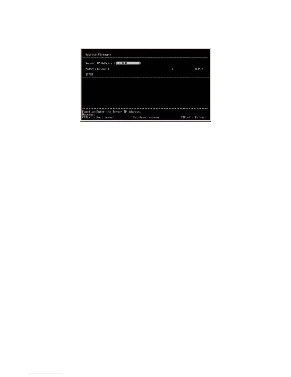
Upgrade Firmware from TFTP Server
This option is used to upgrade system firmware.
FMX-24P
USER’S MANUAL
57
PLANEX COMMUNICATIONS INC.
1) Server IP Address
Enter the IP address of a TFTP server to which a configuration file has been
saved.
2) Path/Filename
Enter the file name of firmware.
3) START
This option initiates the specified action/access to the TFTP server.
4) APPLY
Use this option to store the current configuration to DRAM. Select APPLY to
modify and update the configuration of the switch that is currently running.
Use Configuration File on TFTP Server
Select this option to restore a configuration file that has been saved to an
external TFTP server.

FMX-24P
USER’S MANUAL
58
PLANEX COMMUNICATIONS INC.
1) Server IP Address
Enter the IP address of the TFTP server to which a configuration file has been
saved.
2) Path/Filename
Enter the name of the configuration file that has been saved on the TFTP
server..
3) START
Select this option to initiate the specified action/access to the TFTP server.
4) APPLY
Use this option to store the current configuration to DRAM. Select APPLY to
modify and update the configuration of the switch that is currently running.
Save Settings to TFTP Server
Select this option to save the current configuration of the switch to an external
TFTP server.

FMX-24P
USER’S MANUAL
59
PLANEX COMMUNICATIONS INC.
1) Server IP Address
Enter the IP address of the TFTP server to which you wish to save
configuration.
2) Path/Filename
Enter a file name to save the current configuration.
3) START
Select this option to initiate the specified access/action to the TFTP server.
4) APPLY
Use this option to store the current configuration to DRAM. Select APPLY
to modify and update the configuration of the switch that is currently
running.
Save History Log to TFTP Server
Select this option to save the switch history to an external TFTP server.

FMX-24P
USER’S MANUAL
60
PLANEX COMMUNICATIONS INC.
1) Server IP Address
Enter the IP address of the TFTP server to which you wish to save switch
history.
2) Path/Filename
Enter a file name to save switch history.
3) START
Select this option to initiate the specified action/access to the TFTP server.
4) APPLY
Use this option to store the current configuration to DRAM. Select
APPLY to modify and update the configuration of the switch that is
currently running.
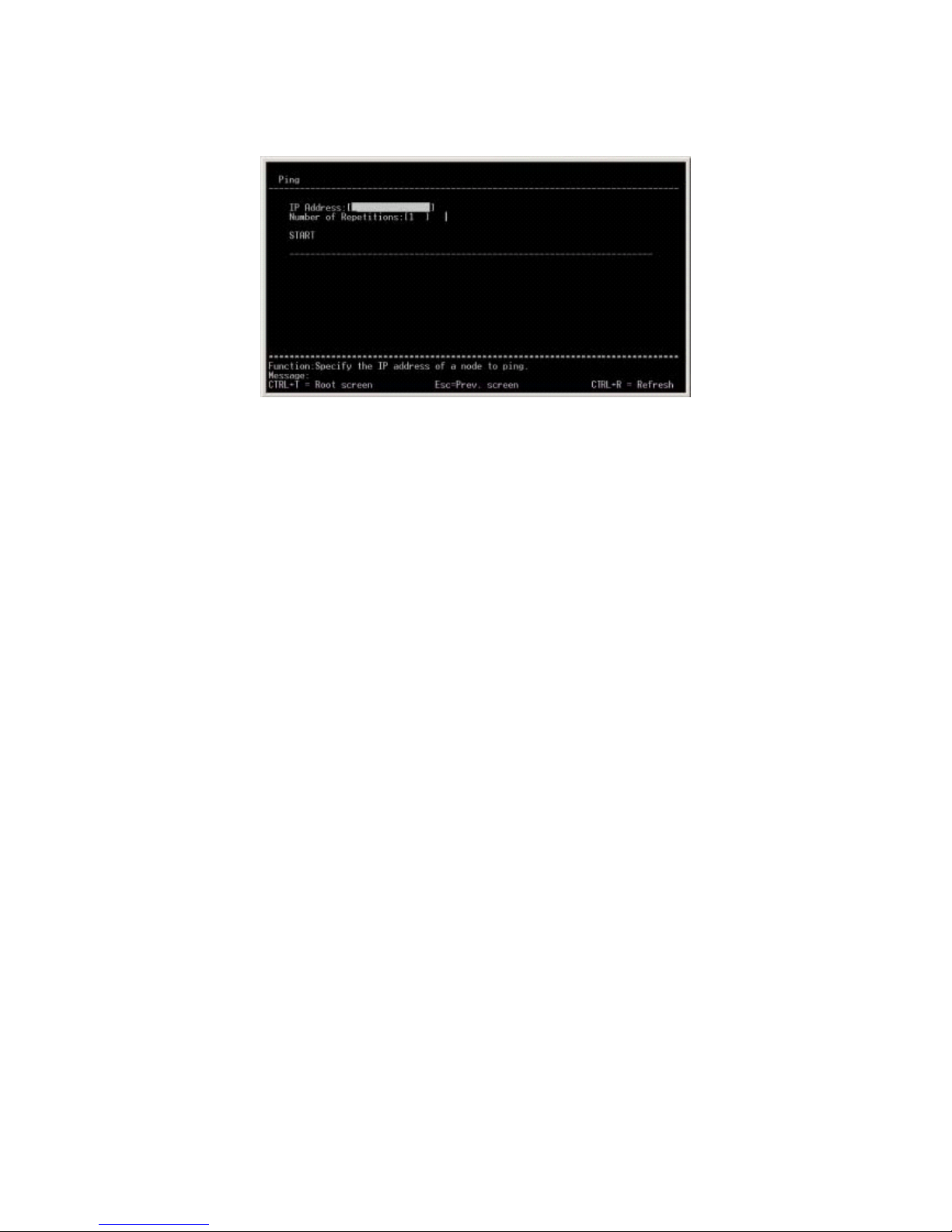
Ping Test
Select this option to perform a communications (PING) test to a specific IP
address.
FMX-24P
USER’S MANUAL
61
PLANEX COMMUNICATIONS INC.
1) IP Address
Enter the IP address of the target device/node.
2) Number of Repetitions
Indicate how many times you wish to perform the PING test. Enter a value
between 0 and 255.
3) Start
Select this option to initiate the PING test.
The result of PING tests will be displayed in the same screen.
4.2.6 Save Changes
Select this option to save the current switch configuration to NV-RAM. The
saved configuration data will be restored when the switch is turned on the next
time.

FMX-24P
USER’S MANUAL
62
PLANEX COMMUNICATIONS INC.
The saving process is complete when the "Press any key to continue…" message
appears.
4.2.7 Reboot
Select this option to reboot the switch. Only users with ADMIN or USER+
access right are allowed to execute this action.
1) Reboot
Select this option to reboot the switch.
2) Save Configuration & Reboot
The switch will reboot itself after saving the current configuration data to
NV-RAM

FMX-24P
USER’S MANUAL
63
PLANEX COMMUNICATIONS INC.
3) Reboot & Load Factory Default Configuration
The switch will reboot itself after restoring the factory default configuration.
4) Reboot & Load Factory Default Configuration Except IP Address
The switch will reboot itself after restoring factory default settings except the
current IP address settings. (Current IP configuration is retained after system
reboot.)
4.2.8 Logout
Select this option to log off from the management screen.

FMX-24P
USER’S MANUAL
64
PLANEX COMMUNICATIONS INC.
5. Sample Configuration
This chapter presents an example of network configuration that utilizes the
FMX-24P.
[FMX-24P used in combination with IP Telephony]
The product supports IEEE802.3af (Power over Ethernet) compliant power supply
function, and is capable of providing power to network devices supporting
IEEE802.3af PoE through a single network cable.
¾ In this configuration, multiple FMX-24P's are used in the same network.
The IP address of each FMX-24P needs to be modified before attaching it to
the network.
¾ The management user name and password are modified.
¾ This configuration utilizes Spanning Tree (STP). Before attaching the switch
to a network, its STP configuration is adjusted.
¾ This configuration utilizes Power over Ethernet (PoE). Before attaching the

FMX-24P
USER’S MANUAL
65
PLANEX COMMUNICATIONS INC.
switch to a network, its PoE configuration is adjusted.
¾ Since this configuration implements SNMP-based management, the SNMP
parameters of the switch are modified.
¾ QoS control is implemented since this configuration incorporates a connection
to IP telephony.
5.1 Configuring IP address
This section provides a sample procedure to assign an IP address to the FMX-24P.
In this example, a network with IP address "192.168.1.0/24" is used. The IP
addresses for the switches are as follows:
FMX-24P(A) 192.168.1.252
FMX-24P(B) 192.168.1.253
FMX-24P(C) 192.168.1.254
To assign the IP addresses above, select [Configuration] - [Configure IP Address]
from the root menu.
1) Get IP From
Select [Manual] to manually assign an IP addresse.
2) IP Address
Enter one of the three IP addresses above.

FMX-24P
USER’S MANUAL
66
PLANEX COMMUNICATIONS INC.
.
3) Subnet Mask
Enter a subnet mask.
4) Default Gateway
No default gateway is used since this configuration utilizes a single network.
4) Management VID
The factory default setting "1" is used since this configuration uses only one
VLAN.
Select [APPLY] after these parameters have been configured. Once IP address
configuration is complete, the new IP configuration is displayed as [Current
Switch IP Settings] in the upper section of the screen.
Sample Configuration : FMX-24P(A)
5.2 Configuring User Name
This section illustrates a sample procedure for configuring a password for
managing the switch. In this example, [planex] is used as user name while [poe]
is used as password. To configure user name and password, select [User Accounts
Management] from the root menu.

FMX-24P
USER’S MANUAL
67
PLANEX COMMUNICATIONS INC.
1) Action
In this example, [Add] is selected to configure user name and password.
2) User Name
[Planex] is used for this configuration.
3) New Password
[poe] is used for this configuration.
4) Confirm New Password
Enter the same password to confirm the correct password.
5) Access Level.
[Root] is selected in this configuration.
After all the parameters above have been configured, select [APPLY]. Once the
configuration is complete, the new user account information will be displayed
under [Current Accounts:] in the lower section of the screen.

FMX-24P
USER’S MANUAL
68
PLANEX COMMUNICATIONS INC.
5.3 Configuring Spanning Tree
This section illustrates a sample procedure for configuring Spanning Tree settings
of the switch. The IEEE802.1D standard value is used for Spanning Tree timer.
In this example, FMX-24P(B) is used as a root bridge while the ports linking
FMX-24P(A) and FMX-24P(C) are set to blocking state.
# Perform the following steps on all the three FMX-24P's:
All ports except the ones used to connect to another switch need to be configured as
[Fast Port]. To enable the Fast Port configuration, select [Configuration] -
[Configure Spanning Tree Protocol] - [Port Settings] from the root menu.
1) View Port
Ports 1 through 22 are configured in this example.

FMX-24P
USER’S MANUAL
69
PLANEX COMMUNICATIONS INC.
2) Configure Port
Select all ports other than those used to connect to another switch.
3) STP Status
Select "Disabled".
4) Port Cost
The parameter is not changed in this example.
5) Priority
The parameter is not changed in this example.
After all the parameters above have been configured, select [APPLY]. The new
configuration will be displayed in the lower section of the screen.
Next, Spanning Tree needs to be enabled on the switch. To enable or disable
Spanning Tree, select [Configuration] - [Configure Spanning Tree Protocol] from
the root menu.

FMX-24P
USER’S MANUAL
70
PLANEX COMMUNICATIONS INC.
1) Status
This option is used to enable/disable Spanning Tree. [Enable] is selected in
this example.
2) Max Age, Hello Time, Forward Delay
The parameter is not changed in this example.
3) Priority
The parameter is not changed in this example.
After all the parameters have been configured, select [APPLY].
# Perform the following steps on the root bridge
This section presents configuration steps for the FMX-24P that serves as a root
bridge. In Spanning Tree, switch with the lowest bridge ID is recognized as the
root bridge. In this example, the priority value of FMX-24P(B) is set to 100. To
change bridging priority, select [Configuration] - [Configure Spanning Tree
Protocol] from the root menu. Then change the priority setting of FMX-24P(B) to
100.

FMX-24P
USER’S MANUAL
71
PLANEX COMMUNICATIONS INC.
5.4 Configuring PoE (Power over Ethernet)
This section illustrates a sample procedure to configure Power over Ethernet on
the switch. The procedure consists of the following two steps:
1) Enable PoE function for the entire switch.
2) Enable PoE function on each port.
In this example, PoE function is enabled on Port 1 through 22 for all the three
units of FMX-24P. To enable PoE over the entire switch, select [Configuration] -
[Configure Switch Information and Advanced Settings] - [ADVANCED SETTINGS]
from the root menu. The factory default setting of this option is [Enabled].
Next, select [Configuration] - [Configure Power Over Lan Settings] - [Configure
Power Ports] from the root menu to enable PoE on each port.

FMX-24P
USER’S MANUAL
72
PLANEX COMMUNICATIONS INC.
1) View Ports
Select the ports you wish to view. In this example, PoE is enabled on Ports 1
through 22.
2) Configure Port from
Select the range of ports you wish to configure.
3) Admin State
Enable or disable PoE on the selected port.
After all the parameters have been configured, select [APPLY]. The new
configuration will appear in the lower section of the screen.

FMX-24P
USER’S MANUAL
73
PLANEX COMMUNICATIONS INC.
5.5 Configuring SNMP
This section illustrates a sample procedure for configuring SNMP on the switch.
The SNMP parameters used and their values are as follows:
Community : planex
Access Right : Read/Write
Trap Manager : 192.168.1.1
Security IP : 192.168.1.1
System Name : FMX-24P(A), FMX-24P(B), FMX-24P(C)
System Location : Access
System Contact : PowerLAN
To configure SNMP community and other parameters, select [SNMP Manager
Configuration] from the root menu.
1) SNMP Community String
This option is used to configure a community name. In this example, the two
factory default community strings (public, private) are deleted and a new
community string, [planex] is added.
2) SNMP Trap Manager Configuration
In this example, the IP address of SNMP Manager (192.168.1.1) is used.
3) Security IP
FMX-24P
USER’S MANUAL
74
PLANEX COMMUNICATIONS INC.
192.168.1.1 is used in this example.
After all the parameters above have been configured, select [APPLY].
Next, configure System Name, System Location and System Contact. To set these
parameters, select [Configuration] - [Configure Switch Information and Advanced
Settings] from the root menu.
After all the parameters above have been configured, select [APPLY].
5.6 Configuring QoS
This last section provides information on configuring QoS parameters on the
switch.
An IP phone is usually equipped with switching functionality. The FMX-24P

FMX-24P
USER’S MANUAL
75
PLANEX COMMUNICATIONS INC.
receives both data from an IP phone and that from a PC through a single port.
Since IP phones cannot send CoS information (for priority control) that is utilized
in most switching hub, TOS values are added to voice packets and transmitted
instead.
The FMX-24P enables prioritized data transfer by allocating CoS value based on
the TOS value received.
*Please note that the actual configuration varies depending on the QoS
functionality provided by the IP phone. This example assumes that TOS priority
values are attached only to data from IP phone (the remaining data do not contain
TOS values).
The configuration procedure consists of the following two steps:
1) Select priority control method.
2) Configure TOS and CoS.
To select a priority control method, select [Configuration] - [Configure Switch
Information and Advanced Settings] - [ADVANCED SETTINGS] from the root
menu.
To configure priority control method for the entire switch, select [Scheduling
Mechanism for CoS Queues]. Since this example uses voice data for which no
delay is allowed, [Strict] is used.

FMX-24P
USER’S MANUAL
76
PLANEX COMMUNICATIONS INC.
Next step concerns configuration to assign TOS values to CoS values. To
configure TOS, select [Configuration] - [Configure DIFFSERV Settings] from the
root menu.
Change Diffserv setting to TOS.
Change Mode setting to [TOS Overwrite 802.1p].
After all the parameters have been configured, select [APPLY].

FMX-24P
USER’S MANUAL
77
PLANEX COMMUNICATIONS INC.
Finally, save configuration to NV-RAM and connect network devices to the product.
 Loading...