


Planex Communications
Head Quarters-Japan
PCI Building
12-7, Nihombashi Odemma-cho, Chuo-ku
Tokyo, 103-0011
www.planex.co.jp
Published: July 2004
Installation and
Configuration Guide
108 Mbps Wireless Access Point
CQW-AP108AG


Installation and Configuration Guide, (CQW-AP108AG) iii
Contents
Preface - - - - - - - - - - - - - - - - - - - - - - - - - - - - - - - - - - - - - - - - - - - - - - - - - - - - - - - - - - - - - - x
1 Overview - - - - - - - - - - - - - - - - - - - - - - - - - - - - - - - - - - - - - - - - - - - - - - - - - - - - - - - - - - - - - 1
Product Overview - - - - - - - - - - - - - - - - - - - - - - - - - - - - - - - - - - - - - - - - - - - - - - - - - - - - - - - - - - - 1
Product Suite - - - - - - - - - - - - - - - - - - - - - - - - - - - - - - - - - - - - - - - - - - - - - - - - - - - - - - - - - - - - - - 1
Features Overview - - - - - - - - - - - - - - - - - - - - - - - - - - - - - - - - - - - - - - - - - - - - - - - - - - - - - - - - - - 2
Radio Resource Management - - - - - - - - - - - - - - - - - - - - - - - - - - - - - - - - - - - - - - - - - - - - - - - - - - 3
Mobility Management - - - - - - - - - - - - - - - - - - - - - - - - - - - - - - - - - - - - - - - - - - - - - - - - - - - - - - - 3
Portal Architecture - - - - - - - - - - - - - - - - - - - - - - - - - - - - - - - - - - - - - - - - - - - - - - - - - - - - - - - - - 4
Security - - - - - - - - - - - - - - - - - - - - - - - - - - - - - - - - - - - - - - - - - - - - - - - - - - - - - - - - - - - - - - - - 5
VLANs - - - - - - - - - - - - - - - - - - - - - - - - - - - - - - - - - - - - - - - - - - - - - - - - - - - - - - - - - - - - - - - - - 5
Quality of Service - - - - - - - - - - - - - - - - - - - - - - - - - - - - - - - - - - - - - - - - - - - - - - - - - - - - - - - - - 6
IP Routing - - - - - - - - - - - - - - - - - - - - - - - - - - - - - - - - - - - - - - - - - - - - - - - - - - - - - - - - - - - - - - - 6
Multiple SSIDs - - - - - - - - - - - - - - - - - - - - - - - - - - - - - - - - - - - - - - - - - - - - - - - - - - - - - - - - - - - 6
Guest Access - - - - - - - - - - - - - - - - - - - - - - - - - - - - - - - - - - - - - - - - - - - - - - - - - - - - - - - - - - - - - 6
Rogue AP Detection and Classification - - - - - - - - - - - - - - - - - - - - - - - - - - - - - - - - - - - - - - - - - - - 7
Standards and Data Rates - - - - - - - - - - - - - - - - - - - - - - - - - - - - - - - - - - - - - - - - - - - - - - - - - - - - - 7
Integration With the Existing Wired Network - - - - - - - - - - - - - - - - - - - - - - - - - - - - - - - - - - - - - - 7
Management Interface Options - - - - - - - - - - - - - - - - - - - - - - - - - - - - - - - - - - - - - - - - - - - - - - - - - 8
2 Planning Your Installation - - - - - - - - - - - - - - - - - - - - - - - - - - - - - - - - - - - - - - - - - - - - - - - - 9
Introduction - - - - - - - - - - - - - - - - - - - - - - - - - - - - - - - - - - - - - - - - - - - - - - - - - - - - - - - - - - - - - - - 9
Example Wireless Network Installation - - - - - - - - - - - - - - - - - - - - - - - - - - - - - - - - - - - - - - - - - - - 9
Assessing Coverage and Capacity Requirements - - - - - - - - - - - - - - - - - - - - - - - - - - - - - - - - - - - - 10
Site Surveys - - - - - - - - - - - - - - - - - - - - - - - - - - - - - - - - - - - - - - - - - - - - - - - - - - - - - - - - - - - - 11
Assessing Security Needs and Architecture - - - - - - - - - - - - - - - - - - - - - - - - - - - - - - - - - - - - - - - - 11
Selecting a Network Management Method - - - - - - - - - - - - - - - - - - - - - - - - - - - - - - - - - - - - - - - - 13
Planning Network Features - - - - - - - - - - - - - - - - - - - - - - - - - - - - - - - - - - - - - - - - - - - - - - - - - - - 14
Example Deployment Scenarios - - - - - - - - - - - - - - - - - - - - - - - - - - - - - - - - - - - - - - - - - - - - - - - - 16
Example 1: Small office, single AP, possible future growth - - - - - - - - - - - - - - - - - - - - - - - - - - - - - 16
Example 2: Small to mid-size business with wireless backhaul - - - - - - - - - - - - - - - - - - - - - - - - - - 18
Example 3: Mid-size business, multiple SSIDs, multiple VLANs - - - - - - - - - - - - - - - - - - - - - - - - - 19
Example 4: Large business, guest access, extended network services - - - - - - - - - - - - - - - - - - - - - - 21
Example 5: Large Campus with Branch Offices - - - - - - - - - - - - - - - - - - - - - - - - - - - - - - - - - - - - 23
3 Installing the Access Point - - - - - - - - - - - - - - - - - - - - - - - - - - - - - - - - - - - - - - - - - - - - - - - 25
Using the Configuration Interfaces - - - - - - - - - - - - - - - - - - - - - - - - - - - - - - - - - - - - - - - - - 25
Hardware Components - - - - - - - - - - - - - - - - - - - - - - - - - - - - - - - - - - - - - - - - - - - - - - - - - - - - - - 25
System Requirements - - - - - - - - - - - - - - - - - - - - - - - - - - - - - - - - - - - - - - - - - - - - - - - - - - - - - - - 25
Installation Requirements - - - - - - - - - - - - - - - - - - - - - - - - - - - - - - - - - - - - - - - - - - - - - - - - - - - - 25

Installation and Configuration Guide, (CQW-AP108AG) iv
Power and Cabling Requirements - - - - - - - - - - - - - - - - - - - - - - - - - - - - - - - - - - - - - - - - - - - - - - 26
Network Information Requirements - - - - - - - - - - - - - - - - - - - - - - - - - - - - - - - - - - - - - - - - - - - - - 26
Installing the Access Point - - - - - - - - - - - - - - - - - - - - - - - - - - - - - - - - - - - - - - - - - - - - - - - - - - - - 26
Using Power Over Ethernet - - - - - - - - - - - - - - - - - - - - - - - - - - - - - - - - - - - - - - - - - - - - - - - - - - 27
Placement and Orientation - - - - - - - - - - - - - - - - - - - - - - - - - - - - - - - - - - - - - - - - - - - - - - - - - - - 27
Verifying the Installation - - - - - - - - - - - - - - - - - - - - - - - - - - - - - - - - - - - - - - - - - - - - - - - - - - - - 28
Interpreting the LEDs - - - - - - - - - - - - - - - - - - - - - - - - - - - - - - - - - - - - - - - - - - - - - - - - - - - - - - 28
Connecting the Serial Port - - - - - - - - - - - - - - - - - - - - - - - - - - - - - - - - - - - - - - - - - - - - - - - - - - - 29
Resetting the Access Point - - - - - - - - - - - - - - - - - - - - - - - - - - - - - - - - - - - - - - - - - - - - - - - - - - - 29
Using the Configuration Interfaces - - - - - - - - - - - - - - - - - - - - - - - - - - - - - - - - - - - - - - - - - - - - - - 30
Using the Web Browser Interface - - - - - - - - - - - - - - - - - - - - - - - - - - - - - - - - - - - - - - - - - - - - - - 30
Using AP Quick Start to Initialize the Access Point - - - - - - - - - - - - - - - - - - - - - - - - - - - - - - - - - - 31
Initializing a Normal AP - - - - - - - - - - - - - - - - - - - - - - - - - - - - - - - - - - - - - - - - - - - - - - - - - - - - 33
Initializing the Portal AP - - - - - - - - - - - - - - - - - - - - - - - - - - - - - - - - - - - - - - - - - - - - - - - - - - - - 36
Navigating the Web Interface - - - - - - - - - - - - - - - - - - - - - - - - - - - - - - - - - - - - - - - - - - - - - - - - - 37
The Home Panel - - - - - - - - - - - - - - - - - - - - - - - - - - - - - - - - - - - - - - - - - - - - - - - - - - - - - - - - - - 37
Quick Start Panels - - - - - - - - - - - - - - - - - - - - - - - - - - - - - - - - - - - - - - - - - - - - - - - - - - - - - - - - 39
Other Panels - - - - - - - - - - - - - - - - - - - - - - - - - - - - - - - - - - - - - - - - - - - - - - - - - - - - - - - - - - - - 45
NM Portal Access - - - - - - - - - - - - - - - - - - - - - - - - - - - - - - - - - - - - - - - - - - - - - - - - - - - - - - - - - 45
Configuration Wizards - - - - - - - - - - - - - - - - - - - - - - - - - - - - - - - - - - - - - - - - - - - - - - - - - - - - - - 45
User Security Wizard - - - - - - - - - - - - - - - - - - - - - - - - - - - - - - - - - - - - - - - - - - - - - - - - - - - - - - 45
Guest Access Wizard - - - - - - - - - - - - - - - - - - - - - - - - - - - - - - - - - - - - - - - - - - - - - - - - - - - - - - - 50
4 Configuring Radio Settings - - - - - - - - - - - - - - - - - - - - - - - - - - - - - - - - - - - - - - - - - - - - - 55
Introduction - - - - - - - - - - - - - - - - - - - - - - - - - - - - - - - - - - - - - - - - - - - - - - - - - - - - - - - - - - - - - - 55
Configuring Radio Parameters - - - - - - - - - - - - - - - - - - - - - - - - - - - - - - - - - - - - - - - - - - - - - - - - 56
Global Configuration - - - - - - - - - - - - - - - - - - - - - - - - - - - - - - - - - - - - - - - - - - - - - - - - - - - - - - 57
Admin State Configuration - - - - - - - - - - - - - - - - - - - - - - - - - - - - - - - - - - - - - - - - - - - - - - - - - - 63
Channel Configuration - - - - - - - - - - - - - - - - - - - - - - - - - - - - - - - - - - - - - - - - - - - - - - - - - - - - - 65
Performance - - - - - - - - - - - - - - - - - - - - - - - - - - - - - - - - - - - - - - - - - - - - - - - - - - - - - - - - - - - - 67
Admission - - - - - - - - - - - - - - - - - - - - - - - - - - - - - - - - - - - - - - - - - - - - - - - - - - - - - - - - - - - - - - 69
Setting the Advanced Radio Configuration - - - - - - - - - - - - - - - - - - - - - - - - - - - - - - - - - - - - - - - - 70
802.11 Policy - - - - - - - - - - - - - - - - - - - - - - - - - - - - - - - - - - - - - - - - - - - - - - - - - - - - - - - - - - - 70
MAC Configuration - - - - - - - - - - - - - - - - - - - - - - - - - - - - - - - - - - - - - - - - - - - - - - - - - - - - - - - 72
Viewing Radio Statistics - - - - - - - - - - - - - - - - - - - - - - - - - - - - - - - - - - - - - - - - - - - - - - - - - - - - - 73
Radio State - - - - - - - - - - - - - - - - - - - - - - - - - - - - - - - - - - - - - - - - - - - - - - - - - - - - - - - - - - - - - 73
Radio Statistics - - - - - - - - - - - - - - - - - - - - - - - - - - - - - - - - - - - - - - - - - - - - - - - - - - - - - - - - - - 76
Viewing Radio Neighbor Details - - - - - - - - - - - - - - - - - - - - - - - - - - - - - - - - - - - - - - - - - - - - - - - 78
Configuring SSID Parameters - - - - - - - - - - - - - - - - - - - - - - - - - - - - - - - - - - - - - - - - - - - - - - - - - 79
SSIDs and Service Profiles - - - - - - - - - - - - - - - - - - - - - - - - - - - - - - - - - - - - - - - - - - - - - - - - - - - 80
SSID Table - - - - - - - - - - - - - - - - - - - - - - - - - - - - - - - - - - - - - - - - - - - - - - - - - - - - - - - - - - - - - 81
SSID Details - - - - - - - - - - - - - - - - - - - - - - - - - - - - - - - - - - - - - - - - - - - - - - - - - - - - - - - - - - - - 83
Profile Table - - - - - - - - - - - - - - - - - - - - - - - - - - - - - - - - - - - - - - - - - - - - - - - - - - - - - - - - - - - - 85
Multiple SSIDs - - - - - - - - - - - - - - - - - - - - - - - - - - - - - - - - - - - - - - - - - - - - - - - - - - - - - - - - - - 86
Managing Client Stations - - - - - - - - - - - - - - - - - - - - - - - - - - - - - - - - - - - - - - - - - - - - - - - - - - - - 87
Stations - - - - - - - - - - - - - - - - - - - - - - - - - - - - - - - - - - - - - - - - - - - - - - - - - - - - - - - - - - - - - - - 88

Installation and Configuration Guide, (CQW-AP108AG) v
Link Statistics - - - - - - - - - - - - - - - - - - - - - - - - - - - - - - - - - - - - - - - - - - - - - - - - - - - - - - - - - - - 89
Security Statistics - - - - - - - - - - - - - - - - - - - - - - - - - - - - - - - - - - - - - - - - - - - - - - - - - - - - - - - - - 90
Configuring Inter Access Point Protocol (IAPP) - - - - - - - - - - - - - - - - - - - - - - - - - - - - - - - - - - - - 91
IAPP Service - - - - - - - - - - - - - - - - - - - - - - - - - - - - - - - - - - - - - - - - - - - - - - - - - - - - - - - - - - - 92
IAPP Topology - - - - - - - - - - - - - - - - - - - - - - - - - - - - - - - - - - - - - - - - - - - - - - - - - - - - - - - - - - 92
IAPP Statistics - - - - - - - - - - - - - - - - - - - - - - - - - - - - - - - - - - - - - - - - - - - - - - - - - - - - - - - - - - 93
Performing Radio Diagnostics - - - - - - - - - - - - - - - - - - - - - - - - - - - - - - - - - - - - - - - - - - - - - - - - - 94
Link Test - - - - - - - - - - - - - - - - - - - - - - - - - - - - - - - - - - - - - - - - - - - - - - - - - - - - - - - - - - - - - - 95
Walk Test - - - - - - - - - - - - - - - - - - - - - - - - - - - - - - - - - - - - - - - - - - - - - - - - - - - - - - - - - - - - - - 98
5 Configuring Networking Settings - - - - - - - - - - - - - - - - - - - - - - - - - - - - - - - - - - - - - - - - - 101
Introduction - - - - - - - - - - - - - - - - - - - - - - - - - - - - - - - - - - - - - - - - - - - - - - - - - - - - - - - - - - - - - 101
Interfaces - - - - - - - - - - - - - - - - - - - - - - - - - - - - - - - - - - - - - - - - - - - - - - - - - - - - - - - - - - - - - - - 101
Configuring Bridging Services - - - - - - - - - - - - - - - - - - - - - - - - - - - - - - - - - - - - - - - - - - - - - - - - 102
Bridge and STP - - - - - - - - - - - - - - - - - - - - - - - - - - - - - - - - - - - - - - - - - - - - - - - - - - - - - - - - - 102
Bridge Statistics - - - - - - - - - - - - - - - - - - - - - - - - - - - - - - - - - - - - - - - - - - - - - - - - - - - - - - - - - 104
ARP Table - - - - - - - - - - - - - - - - - - - - - - - - - - - - - - - - - - - - - - - - - - - - - - - - - - - - - - - - - - - - 104
Configuring IP Routes - - - - - - - - - - - - - - - - - - - - - - - - - - - - - - - - - - - - - - - - - - - - - - - - - - - - - 105
Configuring VLANs - - - - - - - - - - - - - - - - - - - - - - - - - - - - - - - - - - - - - - - - - - - - - - - - - - - - - - - 107
VLAN Table - - - - - - - - - - - - - - - - - - - - - - - - - - - - - - - - - - - - - - - - - - - - - - - - - - - - - - - - - - - 108
Interface VLAN - - - - - - - - - - - - - - - - - - - - - - - - - - - - - - - - - - - - - - - - - - - - - - - - - - - - - - - - 109
User VLAN - - - - - - - - - - - - - - - - - - - - - - - - - - - - - - - - - - - - - - - - - - - - - - - - - - - - - - - - - - - 110
VLAN Statistics - - - - - - - - - - - - - - - - - - - - - - - - - - - - - - - - - - - - - - - - - - - - - - - - - - - - - - - - 112
Configuring Quality of Service - - - - - - - - - - - - - - - - - - - - - - - - - - - - - - - - - - - - - - - - - - - - - - - - 113
Ingress QOS - - - - - - - - - - - - - - - - - - - - - - - - - - - - - - - - - - - - - - - - - - - - - - - - - - - - - - - - - - - 115
Egress COS - - - - - - - - - - - - - - - - - - - - - - - - - - - - - - - - - - - - - - - - - - - - - - - - - - - - - - - - - - - 116
QoS Stats - - - - - - - - - - - - - - - - - - - - - - - - - - - - - - - - - - - - - - - - - - - - - - - - - - - - - - - - - - - - - 117
Configuring Advanced QoS - - - - - - - - - - - - - - - - - - - - - - - - - - - - - - - - - - - - - - - - - - - - - - - - - - 117
Class-Order - - - - - - - - - - - - - - - - - - - - - - - - - - - - - - - - - - - - - - - - - - - - - - - - - - - - - - - - - - - - 118
IP-DSCP - - - - - - - - - - - - - - - - - - - - - - - - - - - - - - - - - - - - - - - - - - - - - - - - - - - - - - - - - - - - - - 119
IP Protocol - - - - - - - - - - - - - - - - - - - - - - - - - - - - - - - - - - - - - - - - - - - - - - - - - - - - - - - - - - - - 120
IP Precedence - - - - - - - - - - - - - - - - - - - - - - - - - - - - - - - - - - - - - - - - - - - - - - - - - - - - - - - - - - 121
Configuring Packet Filters - - - - - - - - - - - - - - - - - - - - - - - - - - - - - - - - - - - - - - - - - - - - - - - - - - - 121
Filter Table - - - - - - - - - - - - - - - - - - - - - - - - - - - - - - - - - - - - - - - - - - - - - - - - - - - - - - - - - - - - 121
Filter Statistics - - - - - - - - - - - - - - - - - - - - - - - - - - - - - - - - - - - - - - - - - - - - - - - - - - - - - - - - - 123
Configuring Interfaces - - - - - - - - - - - - - - - - - - - - - - - - - - - - - - - - - - - - - - - - - - - - - - - - - - - - - 123
Interface Table - - - - - - - - - - - - - - - - - - - - - - - - - - - - - - - - - - - - - - - - - - - - - - - - - - - - - - - - - 124
Interface Statistics - - - - - - - - - - - - - - - - - - - - - - - - - - - - - - - - - - - - - - - - - - - - - - - - - - - - - - - 125
Configuring SNMP - - - - - - - - - - - - - - - - - - - - - - - - - - - - - - - - - - - - - - - - - - - - - - - - - - - - - - - 125
Ping Test - - - - - - - - - - - - - - - - - - - - - - - - - - - - - - - - - - - - - - - - - - - - - - - - - - - - - - - - - - - - - - - 127
6 Configuring a Wireless Backhaul - - - - - - - - - - - - - - - - - - - - - - - - - - - - - - - - - - - - - - - - - 129
Introduction - - - - - - - - - - - - - - - - - - - - - - - - - - - - - - - - - - - - - - - - - - - - - - - - - - - - - - - - - - - - - 129
Use of Radios for Backhaul - - - - - - - - - - - - - - - - - - - - - - - - - - - - - - - - - - - - - - - - - - - - - - - - - 130
Wireless Backhaul Trunks - - - - - - - - - - - - - - - - - - - - - - - - - - - - - - - - - - - - - - - - - - - - - - - - - - 130
Wireless Backhaul security - - - - - - - - - - - - - - - - - - - - - - - - - - - - - - - - - - - - - - - - - - - - - - - - - - 130

Installation and Configuration Guide, (CQW-AP108AG) vi
Setting Up a Wireless Backhaul - - - - - - - - - - - - - - - - - - - - - - - - - - - - - - - - - - - - - - - - - - - - - - - 131
Link Criteria - - - - - - - - - - - - - - - - - - - - - - - - - - - - - - - - - - - - - - - - - - - - - - - - - - - - - - - - - - - 131
Candidate APs - - - - - - - - - - - - - - - - - - - - - - - - - - - - - - - - - - - - - - - - - - - - - - - - - - - - - - - - - - 133
Trunk Table - - - - - - - - - - - - - - - - - - - - - - - - - - - - - - - - - - - - - - - - - - - - - - - - - - - - - - - - - - - - 133
Trunk Statistics - - - - - - - - - - - - - - - - - - - - - - - - - - - - - - - - - - - - - - - - - - - - - - - - - - - - - - - - - 134
7 Managing Security - - - - - - - - - - - - - - - - - - - - - - - - - - - - - - - - - - - - - - - - - - - - - - - - - - - - 137
Introduction - - - - - - - - - - - - - - - - - - - - - - - - - - - - - - - - - - - - - - - - - - - - - - - - - - - - - - - - - - - - - 137
AP Security - - - - - - - - - - - - - - - - - - - - - - - - - - - - - - - - - - - - - - - - - - - - - - - - - - - - - - - - - - - - - 138
Administrative Security - - - - - - - - - - - - - - - - - - - - - - - - - - - - - - - - - - - - - - - - - - - - - - - - - - - - 138
User Security - - - - - - - - - - - - - - - - - - - - - - - - - - - - - - - - - - - - - - - - - - - - - - - - - - - - - - - - - - - - 139
Data Encryption - - - - - - - - - - - - - - - - - - - - - - - - - - - - - - - - - - - - - - - - - - - - - - - - - - - - - - - - - - 139
Configuring Wireless Security - - - - - - - - - - - - - - - - - - - - - - - - - - - - - - - - - - - - - - - - - - - - - - - - 140
Security Mode - - - - - - - - - - - - - - - - - - - - - - - - - - - - - - - - - - - - - - - - - - - - - - - - - - - - - - - - - - 140
SSID Authentication - - - - - - - - - - - - - - - - - - - - - - - - - - - - - - - - - - - - - - - - - - - - - - - - - - - - - 142
Configuring Authentication Zones - - - - - - - - - - - - - - - - - - - - - - - - - - - - - - - - - - - - - - - - - - - - - 145
Authentication Zones - - - - - - - - - - - - - - - - - - - - - - - - - - - - - - - - - - - - - - - - - - - - - - - - - - - - - 145
Authentication Servers - - - - - - - - - - - - - - - - - - - - - - - - - - - - - - - - - - - - - - - - - - - - - - - - - - - - 146
Configuring Administrator Security - - - - - - - - - - - - - - - - - - - - - - - - - - - - - - - - - - - - - - - - - - - - 146
External RADIUS Server Settings - - - - - - - - - - - - - - - - - - - - - - - - - - - - - - - - - - - - - - - - - - - - - 147
Viewing Security Statistics - - - - - - - - - - - - - - - - - - - - - - - - - - - - - - - - - - - - - - - - - - - - - - - - - - - 148
Authentication Statistics - - - - - - - - - - - - - - - - - - - - - - - - - - - - - - - - - - - - - - - - - - - - - - - - - - - 148
Supplicant Statistics - - - - - - - - - - - - - - - - - - - - - - - - - - - - - - - - - - - - - - - - - - - - - - - - - - - - - - 149
Authentication Diagnostics - - - - - - - - - - - - - - - - - - - - - - - - - - - - - - - - - - - - - - - - - - - - - - - - - 151
Configuring Advanced Parameters - - - - - - - - - - - - - - - - - - - - - - - - - - - - - - - - - - - - - - - - - - - - 152
8 Configuring Guest Access - - - - - - - - - - - - - - - - - - - - - - - - - - - - - - - - - - - - - - - - - - - - - - 155
Overview - - - - - - - - - - - - - - - - - - - - - - - - - - - - - - - - - - - - - - - - - - - - - - - - - - - - - - - - - - - - - - - 155
Internal Landing Page - - - - - - - - - - - - - - - - - - - - - - - - - - - - - - - - - - - - - - - - - - - - - - - - - - - - - 156
External Landing Page - - - - - - - - - - - - - - - - - - - - - - - - - - - - - - - - - - - - - - - - - - - - - - - - - - - - - 157
Open Subnet - - - - - - - - - - - - - - - - - - - - - - - - - - - - - - - - - - - - - - - - - - - - - - - - - - - - - - - - - - - 158
Configuring Guest Access - - - - - - - - - - - - - - - - - - - - - - - - - - - - - - - - - - - - - - - - - - - - - - - - - - - 158
Guest Access Services Panel - - - - - - - - - - - - - - - - - - - - - - - - - - - - - - - - - - - - - - - - - - - - - - - - - - 160
Guest Access Security - - - - - - - - - - - - - - - - - - - - - - - - - - - - - - - - - - - - - - - - - - - - - - - - - - - - - 162
9 Managing the Network - - - - - - - - - - - - - - - - - - - - - - - - - - - - - - - - - - - - - - - - - - - - - - - - - 165
Introduction - - - - - - - - - - - - - - - - - - - - - - - - - - - - - - - - - - - - - - - - - - - - - - - - - - - - - - - - - - - - - 165
Using NM Portal - - - - - - - - - - - - - - - - - - - - - - - - - - - - - - - - - - - - - - - - - - - - - - - - - - - - - - - - - - 166
Home Panel - - - - - - - - - - - - - - - - - - - - - - - - - - - - - - - - - - - - - - - - - - - - - - - - - - - - - - - - - - - - 166
Menu Tree - - - - - - - - - - - - - - - - - - - - - - - - - - - - - - - - - - - - - - - - - - - - - - - - - - - - - - - - - - - - - 166
Using the Network Topology Menu - - - - - - - - - - - - - - - - - - - - - - - - - - - - - - - - - - - - - - - - - - - - 167
Enrolling APs - - - - - - - - - - - - - - - - - - - - - - - - - - - - - - - - - - - - - - - - - - - - - - - - - - - - - - - - - - 167
Viewing Backhaul Topology - - - - - - - - - - - - - - - - - - - - - - - - - - - - - - - - - - - - - - - - - - - - - - - - 170
Viewing IP Topology - - - - - - - - - - - - - - - - - - - - - - - - - - - - - - - - - - - - - - - - - - - - - - - - - - - - - 171
Displaying Discovered Radios - - - - - - - - - - - - - - - - - - - - - - - - - - - - - - - - - - - - - - - - - - - - - - - 173
Managing Rogue Access Points - - - - - - - - - - - - - - - - - - - - - - - - - - - - - - - - - - - - - - - - - - - - - - - 175

Installation and Configuration Guide, (CQW-AP108AG) vii
IP Rogue AP Management - - - - - - - - - - - - - - - - - - - - - - - - - - - - - - - - - - - - - - - - - - - - - - - - - - 176
Wireless Rogue AP Management - - - - - - - - - - - - - - - - - - - - - - - - - - - - - - - - - - - - - - - - - - - - - 178
Using the NM Services Menu - - - - - - - - - - - - - - - - - - - - - - - - - - - - - - - - - - - - - - - - - - - - - - - - - 181
Working With Policies - - - - - - - - - - - - - - - - - - - - - - - - - - - - - - - - - - - - - - - - - - - - - - - - - - - - - 181
Configuring Network Discovery - - - - - - - - - - - - - - - - - - - - - - - - - - - - - - - - - - - - - - - - - - - - - - 184
Configuring Portals - - - - - - - - - - - - - - - - - - - - - - - - - - - - - - - - - - - - - - - - - - - - - - - - - - - - - - - 187
Configuring the DHCP Server - - - - - - - - - - - - - - - - - - - - - - - - - - - - - - - - - - - - - - - - - - - - - - - 190
Managing Network Faults - - - - - - - - - - - - - - - - - - - - - - - - - - - - - - - - - - - - - - - - - - - - - - - - - - - 194
Viewing Alarms - - - - - - - - - - - - - - - - - - - - - - - - - - - - - - - - - - - - - - - - - - - - - - - - - - - - - - - - - 194
Viewing the Syslog - - - - - - - - - - - - - - - - - - - - - - - - - - - - - - - - - - - - - - - - - - - - - - - - - - - - - - - 204
Managing Users - - - - - - - - - - - - - - - - - - - - - - - - - - - - - - - - - - - - - - - - - - - - - - - - - - - - - - - - - - 205
Adding Wireless Users - - - - - - - - - - - - - - - - - - - - - - - - - - - - - - - - - - - - - - - - - - - - - - - - - - - - 205
Adding Administrative Users - - - - - - - - - - - - - - - - - - - - - - - - - - - - - - - - - - - - - - - - - - - - - - - - 207
Adding MAC-ACL Users - - - - - - - - - - - - - - - - - - - - - - - - - - - - - - - - - - - - - - - - - - - - - - - - - - 208
10 Maintaining the Access Point - - - - - - - - - - - - - - - - - - - - - - - - - - - - - - - - - - - - - - - - - - - - 211
Rebooting the AP - - - - - - - - - - - - - - - - - - - - - - - - - - - - - - - - - - - - - - - - - - - - - - - - - - - - - - - - - 211
Managing the System Configuration - - - - - - - - - - - - - - - - - - - - - - - - - - - - - - - - - - - - - - - - - - - 211
IP Configuration - - - - - - - - - - - - - - - - - - - - - - - - - - - - - - - - - - - - - - - - - - - - - - - - - - - - - - - - 212
Syslog Configuration - - - - - - - - - - - - - - - - - - - - - - - - - - - - - - - - - - - - - - - - - - - - - - - - - - - - - 213
License Management - - - - - - - - - - - - - - - - - - - - - - - - - - - - - - - - - - - - - - - - - - - - - - - - - - - - - 214
NMS Configuration - - - - - - - - - - - - - - - - - - - - - - - - - - - - - - - - - - - - - - - - - - - - - - - - - - - - - - 214
Hardware Options - - - - - - - - - - - - - - - - - - - - - - - - - - - - - - - - - - - - - - - - - - - - - - - - - - - - - - - 215
Managing the AP Configuration - - - - - - - - - - - - - - - - - - - - - - - - - - - - - - - - - - - - - - - - - - - - - - 216
Secure Backup - - - - - - - - - - - - - - - - - - - - - - - - - - - - - - - - - - - - - - - - - - - - - - - - - - - - - - - - - - 216
Configuration Reports - - - - - - - - - - - - - - - - - - - - - - - - - - - - - - - - - - - - - - - - - - - - - - - - - - - - 217
Reset Configuration - - - - - - - - - - - - - - - - - - - - - - - - - - - - - - - - - - - - - - - - - - - - - - - - - - - - - - 219
TFTP Backup - - - - - - - - - - - - - - - - - - - - - - - - - - - - - - - - - - - - - - - - - - - - - - - - - - - - - - - - - - - 220
Upgrading Software - - - - - - - - - - - - - - - - - - - - - - - - - - - - - - - - - - - - - - - - - - - - - - - - - - - - - - - 221
Software Image File - - - - - - - - - - - - - - - - - - - - - - - - - - - - - - - - - - - - - - - - - - - - - - - - - - - - - - 222
Upgrading the AP Software - - - - - - - - - - - - - - - - - - - - - - - - - - - - - - - - - - - - - - - - - - - - - - - - - 222
Canceling a Distribution - - - - - - - - - - - - - - - - - - - - - - - - - - - - - - - - - - - - - - - - - - - - - - - - - - - 225
Download Status - - - - - - - - - - - - - - - - - - - - - - - - - - - - - - - - - - - - - - - - - - - - - - - - - - - - - - - - 225
Image Recovery - - - - - - - - - - - - - - - - - - - - - - - - - - - - - - - - - - - - - - - - - - - - - - - - - - - - - - - - - 226
Common Problems and Solutions - - - - - - - - - - - - - - - - - - - - - - - - - - - - - - - - - - - - - - - - - - - - - - 226
A Using the Command Line Interface - - - - - - - - - - - - - - - - - - - - - - - - - - - - - - - - - - - - - - - - 229
Using the Command Line Interface - - - - - - - - - - - - - - - - - - - - - - - - - - - - - - - - - - - - - - - - - - - - 229
Using the Console Port for CLI Access - - - - - - - - - - - - - - - - - - - - - - - - - - - - - - - - - - - - - - - - - - 230
B Regulatory and License Information - - - - - - - - - - - - - - - - - - - - - - - - - - - - - - - - - - - - - - - 233
C Alarms - - - - - - - - - - - - - - - - - - - - - - - - - - - - - - - - - - - - - - - - - - - - - - - - - - - - - - - - - - - - - 235
Discovery: Discovered new node - - - - - - - - - - - - - - - - - - - - - - - - - - - - - - - - - - - - - - - - - - - - - - 237
Discovery: Node deleted from network - - - - - - - - - - - - - - - - - - - - - - - - - - - - - - - - - - - - - - - - - - 237
Discovery: Managed nodes limit exceeded - - - - - - - - - - - - - - - - - - - - - - - - - - - - - - - - - - - - - - - 238
Enrollment: Node Enrolled - - - - - - - - - - - - - - - - - - - - - - - - - - - - - - - - - - - - - - - - - - - - - - - - - - 238

Installation and Configuration Guide, (CQW-AP108AG) viii
Enrollment: Node Un-enrolled - - - - - - - - - - - - - - - - - - - - - - - - - - - - - - - - - - - - - - - - - - - - - - - - 239
Policy: Policy Download Successful - - - - - - - - - - - - - - - - - - - - - - - - - - - - - - - - - - - - - - - - - - - - 240
Policy: Policy Download Failed - - - - - - - - - - - - - - - - - - - - - - - - - - - - - - - - - - - - - - - - - - - - - - - 240
Software Download: Image Download Succeeded - - - - - - - - - - - - - - - - - - - - - - - - - - - - - - - - - - 241
Software Download: Image Download Failed - - - - - - - - - - - - - - - - - - - - - - - - - - - - - - - - - - - - - 241
Software Download: Software Distribution Succeeded - - - - - - - - - - - - - - - - - - - - - - - - - - - - - - - 242
Wireless: Radio enabled (BSS Enabled) - - - - - - - - - - - - - - - - - - - - - - - - - - - - - - - - - - - - - - - - - 243
Wireless: Radio Disabled (BSS disabled) - - - - - - - - - - - - - - - - - - - - - - - - - - - - - - - - - - - - - - - - 243
Wireless: BSS Enabling Failed - - - - - - - - - - - - - - - - - - - - - - - - - - - - - - - - - - - - - - - - - - - - - - - - 244
Wireless: Frequency Changed - - - - - - - - - - - - - - - - - - - - - - - - - - - - - - - - - - - - - - - - - - - - - - - - 244
Wireless: STA Association Failed - - - - - - - - - - - - - - - - - - - - - - - - - - - - - - - - - - - - - - - - - - - - - - 245
Wireless: STA Associated - - - - - - - - - - - - - - - - - - - - - - - - - - - - - - - - - - - - - - - - - - - - - - - - - - - 246
Wireless: STA Disassociated - - - - - - - - - - - - - - - - - - - - - - - - - - - - - - - - - - - - - - - - - - - - - - - - - 247
Wireless: WDS Failed - - - - - - - - - - - - - - - - - - - - - - - - - - - - - - - - - - - - - - - - - - - - - - - - - - - - - - 248
Wireless: WDS Up - - - - - - - - - - - - - - - - - - - - - - - - - - - - - - - - - - - - - - - - - - - - - - - - - - - - - - - - 249
Wireless: WDS Down - - - - - - - - - - - - - - - - - - - - - - - - - - - - - - - - - - - - - - - - - - - - - - - - - - - - - - 249
Security: Guest Authentication Succeeded - - - - - - - - - - - - - - - - - - - - - - - - - - - - - - - - - - - - - - - 250
Security: Guest Authentication Failed - - - - - - - - - - - - - - - - - - - - - - - - - - - - - - - - - - - - - - - - - - 251
Security: User rejected by RADIUS Server - - - - - - - - - - - - - - - - - - - - - - - - - - - - - - - - - - - - - - - 252
Security: BP rejected by RADIUS Server - - - - - - - - - - - - - - - - - - - - - - - - - - - - - - - - - - - - - - - - 252
Security: RADIUS Server timeout - - - - - - - - - - - - - - - - - - - - - - - - - - - - - - - - - - - - - - - - - - - - - 253
Security: Management User login success - - - - - - - - - - - - - - - - - - - - - - - - - - - - - - - - - - - - - - - - 254
Security: Management User login failure - - - - - - - - - - - - - - - - - - - - - - - - - - - - - - - - - - - - - - - - 255
Security: STA failed EAPOL MIC check - - - - - - - - - - - - - - - - - - - - - - - - - - - - - - - - - - - - - - - - 255
Security: STA attempting WPA PSK – no Pre-shared Key is set for SSID - - - - - - - - - - - - - - - - - 256
Security: Auth Server Improperly configured on this SSID - - - - - - - - - - - - - - - - - - - - - - - - - - - 257
Security: STA failed to send EAPOL-Start - - - - - - - - - - - - - - - - - - - - - - - - - - - - - - - - - - - - - - - 258
Security: RADIUS sent a bad response - - - - - - - - - - - - - - - - - - - - - - - - - - - - - - - - - - - - - - - - - - 259
Security: RADIUS timeout too short - - - - - - - - - - - - - - - - - - - - - - - - - - - - - - - - - - - - - - - - - - - 259
Security: STA authentication did not complete in time - - - - - - - - - - - - - - - - - - - - - - - - - - - - - - - 260
Security: Upstream AP is using an untrusted auth server - - - - - - - - - - - - - - - - - - - - - - - - - - - - - 261
Security: Upstream AP is using a non-portal node as its auth server - - - - - - - - - - - - - - - - - - - - - 262
Security: Upstream AP failed MIC check during BP authentication - - - - - - - - - - - - - - - - - - - - - 263
Security: Premature EAP-Success received - - - - - - - - - - - - - - - - - - - - - - - - - - - - - - - - - - - - - - - 263
Security: Profile not configured for user-group - - - - - - - - - - - - - - - - - - - - - - - - - - - - - - - - - - - - 264
Security: STA has failed security enforcement check - - - - - - - - - - - - - - - - - - - - - - - - - - - - - - - - 265
Security: Guest Authentication Failed - - - - - - - - - - - - - - - - - - - - - - - - - - - - - - - - - - - - - - - - - - 267
Security: AP Detected Bad TKIP MIC - - - - - - - - - - - - - - - - - - - - - - - - - - - - - - - - - - - - - - - - - - 268
Security: BP Detected Bad TKIP MIC on Incoming Unicast - - - - - - - - - - - - - - - - - - - - - - - - - - 269
Security: BP Detected Bad TKIP MIC on Incoming Multicast/Broadcast - - - - - - - - - - - - - - - - - 269
Security: STA Detected Bad TKIP MIC on Incoming Unicast - - - - - - - - - - - - - - - - - - - - - - - - - 270
Security: STA Detected Bad TKIP MIC on Incoming Multicast/Broadcast - - - - - - - - - - - - - - - - 271
Security: TKIP counter-measures lockout period started - - - - - - - - - - - - - - - - - - - - - - - - - - - - - 271
Security: EAP User-ID timeout - - - - - - - - - - - - - - - - - - - - - - - - - - - - - - - - - - - - - - - - - - - - - - - 272
Security: EAP response timeout - - - - - - - - - - - - - - - - - - - - - - - - - - - - - - - - - - - - - - - - - - - - - - - 273

Installation and Configuration Guide, (CQW-AP108AG) ix
Security: EAPOL Key exchange – message 2 timeout - - - - - - - - - - - - - - - - - - - - - - - - - - - - - - - 274
Security: EAPOL Group 2 key exchange timeout - - - - - - - - - - - - - - - - - - - - - - - - - - - - - - - - - - 275
Glossary - - - - - - - - - - - - - - - - - - - - - - - - - - - - - - - - - - - - - - - - - - - - - - - - - - - - - - - - - - - - 277
Index - - - - - - - - - - - - - - - - - - - - - - - - - - - - - - - - - - - - - - - - - - - - - - - - - - - - - - - - - - - - - - 283

Installation and Configuration Guide, (CQW-AP108AG) x
Preface
This guide explains how to install and configure the 108 Mbps Wireless Access Point (108 Mbps
Wireless AP), which is used with Wi-Fi certified clients to provide PC laptop and desktop users
with wireless network access.
The 108 Mbps Wireless Access Point provides the following features:
• High throughput and range through dual-band radio transceivers
• Easy installation
• Wireless networking features that include bridging, VLAN, Quality of Service (QoS), IP
routing, and network backhaul capabilities
• Comprehensive security that includes support for WEP, TKIP, AES, EAP-PEAP, EAP-TLS,
and RADIUS
• Automated radio resource management, including controls for operating channels, capacity,
and range
• Policy-based management
Audience
This guide is designed to help you install and configure the 108 Mbps Wireless Access Point
successfully even if you are unfamiliar with wireless networking technology. Some familiarity with
local area networking technology is assumed. If you encounter a term or acronym with which you
are unfamiliar, refer to the glossary at the end of the guide, just before the index.
Organization of this Guide
This guide consists of the following chapters:
• Chapter 1, “Overview,” provides a high-level overview of the 108 Mbps Wireless Access
Point products.
• Chapter 2, “Planning Your Installation,” describes various deployment scenarios and helps
determine how many 108 Mbps Wireless Access Points will be needed and the appropriate
network management scheme.
• Chapter 3, “Installing the Access Point,” describes how to install the 108 Mbps Wireless
Access Point and how to use the Quick Start panels for fast and easy configuration. Also
explains how to use the 108 Mbps Wireless AP web interface.
• Chapter 4, “Configuring Radio Settings,” explains how to configure the 108 Mbps Wireless
Access Point radios.
• Chapter 5, “Configuring Networking Settings,” explains how to configure the advanced
networking features of the 108 Mbps Wireless Access Point.
• Chapter 6, “Configuring a Wireless Backhaul,” explains how to use the wireless backhaul
feature to configure a wireless distribution system that can cover a large area with limited wired
network connectivity.
• Chapter 7, “Managing Security,” describes the encryption and authentication features of the
108 Mbps Wireless Access Point and explains how configure the security options.

Preface
xi Installation and Configuration Guide, (CQW-AP108AG)
• Chapter 8, “Configuring Guest Access,” describes how to configure guest access for the
network.
• Chapter 9, “Managing the Network,” explains how to use the NM Portal features of the 108
Mbps Wireless Access Point to manage multiple APs across your network.
• Chapter 10, “Maintaining the Access Point,” describes the tools available to maintain the
108 Mbps Wireless Access Point.
• Appendix A, “Using the Command Line Interface,” describes how to use the console and
command line interface (CLI) to configure the 108 Mbps Wireless Access Point, with crossreferences to the PLANEX Command Line Interface Reference Manual.
• Appendix B, “Regulatory and License Information,” provides regulatory specifications. for
the 108 Mbps Wireless Access Point.
• Appendix C, “Alarms,” provides a description of the alarms generated by the 108 Mbps
Wireless Access Point.
• Glossary— Provides definitions for acronyms, networking terminology, and PLANEXspecific terms.
Conventions Used in this Guide
This guide uses the following conventions for instructions and information.
Notes, Cautions, and Warnings
Notes, cautions, and time-saving tips use the following conventions and symbols.
Command Conventions
Table 1 describes the command syntax used in this document.
NOTE: Notes contain helpful suggestions or information that may be of
importance to the task at hand.
CAUTION: Caution indicates that there is a risk of equipment damage or loss
of data when certain actions are performed.
WARNING: Warnings are intended to alert you to situations that could result
in injury (such as exposure to electric current, for example).
Table 1:Command Conventions
Convention Description
boldface Commands and keywords.
italic Command input that is supplied by you.
[ ] Optional keywords and default responses to system
prompts appear within square brackets.
{x | x | x} A choice of keywords (represented by x) appears in
braces separated by vertical bars. You must select one.
Ctrl Represents the key labeled Ctrl. For example, when you
read ^D or Ctrl-D, you should hold down the Control
key while you press the D key.
panel font
Examples of information displayed on a panel.
boldface panel font
Examples of information the user must enter.

Preface
Installation and Configuration Guide, (CQW-AP108AG) xii
Related Documentation
The following documentation related to the PLANEX wireless networking product line is available
on CD-ROM and also on the PLANEX website, http://www.planex.co.jp.
• 㪧㪣㪘㪥㪜㪯㩷㪈㪇㪏㩷㪤㪹㫇㫊㩷㪮㫀㫉㪼㫃㪼㫊㫊㩷㪣㪘㪥㩷㪧㪚㩷㪚㪸㫉㪻
㪧㪣㪘㪥㪜㪯㩷㪈㪇㪏㩷㪤㪹㫇㫊㩷㪮㫀㫉㪼㫃㪼㫊㫊㩷㪣㪘㪥㩷㪧㪚㩷㪚㪸㫉㪻㪧㪣㪘㪥㪜㪯㩷㪈㪇㪏㩷㪤㪹㫇㫊㩷㪮㫀㫉㪼㫃㪼㫊㫊㩷㪣㪘㪥㩷㪧㪚㩷㪚㪸㫉㪻
㪧㪣㪘㪥㪜㪯㩷㪈㪇㪏㩷㪤㪹㫇㫊㩷㪮㫀㫉㪼㫃㪼㫊㫊㩷㪣㪘㪥㩷㪧㪚㩷㪚㪸㫉㪻㩷(CQW-NS108AG)㩷㪠㫅㫊㫋㪸㫃㫃㪸㫋㫀㫆㫅㩷㪸㫅㪻㩷㪬㫊㪼㫉㫊㩷㪞㫌㫀㪻㪼
㪠㫅㫊㫋㪸㫃㫃㪸㫋㫀㫆㫅㩷㪸㫅㪻㩷㪬㫊㪼㫉㫊㩷㪞㫌㫀㪻㪼㪠㫅㫊㫋㪸㫃㫃㪸㫋㫀㫆㫅㩷㪸㫅㪻㩷㪬㫊㪼㫉㫊㩷㪞㫌㫀㪻㪼
㪠㫅㫊㫋㪸㫃㫃㪸㫋㫀㫆㫅㩷㪸㫅㪻㩷㪬㫊㪼㫉㫊㩷㪞㫌㫀㪻㪼㩷
— Explains how to install and configure the PLANEX Wireless LAN Client Adapter, which
provides PC laptop and desktop users with access to the PLANEX Access Point products.
• PLANEX Wireless LAN Network Management Software Installation and Configuration
Guide — Explains how to use PLANEX Wireless LAN Network Management Software to
manage an enterprise wireless network.
• PLANEX Command Line Interface (CLI) Reference Manual — Provides a listing of all the
commands available for PLANEX wireless products through serial console access and the
command line interface. Intended for advanced users and system administrators.

Preface
xiii Installation and Configuration Guide, (CQW-AP108AG)

Installation and Configuration Guide, (CQW-AP108AG) 1
1
Overview
This chapter introduces the features and capabilities of the 108 Mbps Wireless Access Point and
presents the following topics:
• Product Overview
• Features Overview
• Standards and Data Rates
• Radio Resource Management
• Mobility Management
• Portal Architecture
• Security
• Integration With the Existing Wired Network
• Management Interface Options
Product Overview
The 108 Mbps Wireless Access Point is part of an innovative suite of wireless technology products
designed to dramatically improve the quality and convenience of wireless networking. By greatly
increasing the range, speed, reliability, security, and ease-of-use of wireless LAN (WLAN)
systems, PLANEX products help to promote the mainstream adoption of wireless technology, and
help to foster new wireless applications.
Product Suite
The PLANEX product suite comprises these wireless networking products:
• 108 Mbps Wireless Access Point
• 108Mbps Wireless LAN PC Card
• PLANEX Professional Network Management System (Wireless LAN Network Management
Software)
108 Mbps Wireless Access Points
108 Mbps Wireless Access Points (108 Mbps Wireless AP) provide network connectivity for
wireless client stations. Incorporating the latest technological advances in radio design and
implementation, the dual-radio 108 Mbps Wireless Access Point offers very high wireless
performance, financial-grade security, and extended wireless coverage.
108Mbps Wireless LAN PC Card
The 108Mbps Wireless LAN PC Card provides the communications link between laptop or desktop
PC users and wireless network. Available in PC Card and Mini PCI Card form factors, the
108Mbps Wireless LAN PC Card is designed to take full advantage of the performance, range,
security, and management capabilities of the 108 Mbps Wireless Access Point. For more
information, refer to the 108Mbps Wireless LAN PC Card Installation and User Guide.

1 Overview
2 Installation and Configuration Guide, (CQW-AP108AG)
PLANEX Wireless LAN Network Management Software
PLANEX’s Wireless LAN Network Management Software provides enterprise-class management
for the wireless network, including complete configuration and image control, security, and
performance and fault monitoring. For more information, refer to the Wireless LAN Network
Management Software Installation and Configuration Guide.
Figure 1 shows how PLANEX products operate in concert to create a wireless network.
Figure 1: PLANEX Wireless Network
Features Overview
108 Mbps Wireless Access Points extend the range, coverage, and bandwidth of traditional wireless
equipment, while also supporting the latest network security and management features. All 108
Mbps Wireless Access Point models include the following features:
• Dual radios, each operating in 802.11b/g or 802.11a mode
• Optional PLANEX enhanced data rates up to 108 Mbps
• Automated frequency management
• Cell size and range management
• Support for all current IEEE 802.11 standards and draft versions of 802.11 standards
• Multiple SSID support
• Bridging, including layer 2 filtering, encapsulation modes, 802.1x support, and static
forwarding
• Easy installation and configuration
• Single and multiple VLAN support, interface-based and user-based
• 802.11 roaming support
• Web and command line user interfaces
Client(s)
DNS & DHCP
Server
RADIUS
Server
Access
Point
Wireless Clients
Wireless Clients Wireless Clients
Access
Point
Access
Point
Enterprise
Network
A0001D
NMS Pro
Server

Features Overview
Installation and Configuration Guide, (CQW-AP108AG) 3
• Embedded Network Management and Security Portal services
• Financial grade security
• Effective security management
• Guest user access
• Rogue AP detection
• Quality of service (QoS)
• Wireless backhaul modes
• Integration with existing wired network infrastructure
• Static IP routing
• SNMP MIB support
• Authentication using RADIUS services
• Software and firmware upgrades
• Back up and restoration of AP configuration data
• SYSLOG and diagnostic tools for monitoring and troubleshooting
Radio Resource Management
The 108 Mbps Wireless AP supports management of radio channels, cell size, and range.
Channel management features include automatic channel selection, support for international
channel sets, dynamic channel changes in response to network conditions, and the ability to assign
channels manually to fine tune channel quality. Cell size and range capabilities enable you to
optimize equipment placement, eliminate dead spots, and reduce interference.
Mobility Management
Mobility management features include Layer 2 roaming (as users move from one coverage area of
an access point to another or are switched for load balancing purposes), quality of service support,
and comprehensive security features. The 108 Mbps Wireless AP also provides support for 802.11f
based Inter-Access Point Protocol (IAPP).

1 Overview
4 Installation and Configuration Guide, (CQW-AP108AG)
Portal Architecture
To support the range of network sizes and configurations served by PLANEX products, PLANEX
has designed a built-in, flexible, portal services architecture for management and security. Each AP
can be configured as an NM Portal AP to support the following services:
Figure 2 illustrates portal services within the PLANEX network. NM Portal provides overall
network management functionality and monitoring. The enrollment portal feature enables
verification of additional APs and authorization for operation in the network. The security portal
feature verifies the identity of individual users wanting access to the network.
Figure 2: Portal Services
Regardless of network size, configuring one or more 108 Mbps Wireless APs as NM Portals yields
the following benefits:
• Even with as few as two APs in a network, NM Portal offers a single point of focus for
monitoring the network and managing security. Configuring the first AP as an NM Portal
makes it easy to enroll additional APs.
Service Description
Management NM Portal services provide network management functionality for small to
mid-size wireless networks. Each 108 Mbps Wireless AP configured as an
NM Portal can operate in stand-alone mode to provide network management
for the entire network or as a location or branch manager working in
conjunction with Wireless LAN Network Management Software, the
PLANEX Professional Network Management System.
Security Security portal services include support for secure user authentication by way
of a RADIUS server internal to the 108 Mbps Wireless AP. Security portal
services are part of NM Portal, but can also be configured independently for
backup authentication in the event that the primary internal RADIUS server
becomes unavailable.
Enrollment Each PLANEX wireless network requires an enrollment server to verify the
identity of 108 Mbps Wireless APs and authorize them for operation in the
network. The enrollment portal feature is automatically enabled in the access
point as part of NM Portal. NM Portal should be used for enrollment unless
Wireless LAN Network Management Software has been implemented as the
enterprise network management solution.
A0028B
NM Portal:
Manage and
Monitor the
Network
Other APs
Enrollment Portal:
Verify AP Identity
Security Portal:
Authenticate Clients

Features Overview
Installation and Configuration Guide, (CQW-AP108AG) 5
• The configuration of the NM Portal AP is easily distributed to the other APs in the network,
assuring consistent application of configuration parameters.
• NM Portal can provide user authentication services for an entire small to mid size network or
serve as a backup security server if an external RADIUS authentication service is used.
Security
PLANEX offers a comprehensive security solution that adheres to the following industry standards
and draft standards:
• Data encryption—WEP, Wi-Fi Protected Access (WPA) with TKIP or AES encryption
• User authentication—IEEE 802.1x authentication, including EAP-PEAP or EAP-TLS; WPA-
PSK
• Key management—Microsoft-IAS, FUNK-RADIUS, PLANEX Wireless LAN Network
Management Software, PLANEX integrated security portal, and manual key management
capabilities
These features are part of a security architecture that provides the wireless network a greater degree
of security than most traditional wired networks. The following security features are included with
all 108 Mbps Wireless AP:
• Built-in maximum industry-standard security
• Auto-detection of the security capability of clients and APs
• Policy-based configuration of security settings
• Hardware support for high-performance encryption
• Support for installations ranging from the small-office/home-office (SOHO) to multi-site
enterprises
• Command-line access using SSH (secure shell)
• Web-based management interface and policy-based management using HTTPS (SSL)
• SNMP management interface through SNMPv3
• IEEE 802.11i standards
• User-authentication using EAP-TLS, EAP-PEAP, WPA-PSK, WEP
• Rogue AP detection
• Rogue client detection
VLANs
By decoupling traffic flow and network services from the physical network topology, virtual LANs
(VLANs) enable enterprises improve network traffic flow, increase load, and deliver varying levels
of service and access to different groups of users. The 108 Mbps Wireless AP VLAN feature
readily extends an existing wired VLAN structure to the wireless network. It can also be used to
implement new network privileges and services; for example, user VLANs are integral to the
PLANEX guest access feature (see “Guest Access” on page 6).
PLANEX supports interface-based VLANs and user-based VLANs. Interface VLANs separate
traffic according to the Ethernet and radio interfaces on the 108 Mbps Wireless AP. Packets
destined for a specific interface VLAN are directed to the port with that VLAN assigned. By
contrast, user VLANs separate traffic according to user groups. Users can be assigned to the same
VLAN even if they are in different physical LANs and at geographically dispersed locations. User
VLANs are useful for managing manage enterprise work groups and differentiating among

1 Overview
6 Installation and Configuration Guide, (CQW-AP108AG)
categories of users. The 108 Mbps Wireless Access Point supports up to 16 VLANs, including a
default VLAN.
Quality of Service
Quality of Service (QoS) features enable differential treatment of network traffic types to support
special applications or extend priority access to designated groups of users. For example,
applications as streaming media and voice over Internet suffer serious quality degradation if data
transmission is interrupted or bandwidth fluctuates excessively. You can assign a higher quality of
service to applications of this type, while still maintaining adequate service for less intensive
applications such as print and file sharing. Network utilization is increased with little to no negative
effect on user productivity. QoS can also be used to lower the priority for non-critical applications.
For example, FTP transfers, which are generally not time critical but can consume significant
network bandwidth, can be assigned lower priority than streaming media applications or database
transactions.
QoS can also be assigned on a user group basis. For example, network administrators can be
assigned a higher quality of service than other employees, thereby enhancing their ability to
manage and troubleshoot a heavily loaded network.
PLANEX implements quality of service features using classes of service (COS). Eight COS levels
are available for assignment according to user or application based rules. The COS approach does
not guarantee bandwidth, but it does give “best effort” priority according to the assigned level. A
flexible approach to service quality, it scales easily and accommodates a variety of mapping rules.
MAC layer mappings for COS levels and COS to IP layer mappings are supported, and priority
settings can be assigned for different COS mapping rules.
IP Routing
IP routing adds flexibility to AP management and expands the addressing capability of the AP. You
can specify static IP addresses outside the local subnet along with routing information to reach the
addresses.
Multiple SSIDs
The 108 Mbps Wireless AP supports multiple SSIDs within each individual AP. Using the multiple
SSID feature, users can access separate networks through a single physical infrastructure. For
example, if you want to create different levels of resource access for employees and visitors, you
can create two SSIDs, one with high security and one with open security.
Guest Access
The 108 Mbps Wireless AP supports flexible, secure managing of guest access at corporate
locations. By contrast with most other guest access solutions, the 108 Mbps Wireless AP supports
guest access without requiring any changes to the physical network topology. VLAN tags on the
existing access points segregate users into corporate and guest VLANs, and guests are
automatically directed to an internal or external web landing page. Guest passwords can be
assigned statically or change dynamically according to a pre-set schedule. An open access option is
available to provide unauthenticated guests with access to an open subnet.

Standards and Data Rates
Installation and Configuration Guide, (CQW-AP108AG) 7
Rogue AP Detection and Classification
Maintaining a secure wireless network requires ongoing monitoring of potential rogue access
points and the ability to classify them as known to the local or neighboring network, or as true
rogues. The network management functions of NM Portal include automatic network scanning and
display of all the detected APs that potentially qualify as rogues. Using the information included in
the display, network administrators can identify and classify the APs that are known. The
remaining APs are classified as rogues. By examining the information available for each rogue AP,
it is generally possible to pinpoint the location of the rogue and take action to remove it from the
network.
Standards and Data Rates
PLANEX supports the wireless networking standards shown in Table 2.
The 802.11 standard specifies the following data rates:
• 802.11b: DSSS (1, 2, 5.5 and 11 Mbps)
• 802.11a: OFDM (6, 9, 12, 18, 24, 36, 48, 54 Mbps)
• 802.11g: OFDM (6, 9, 12, 18, 24, 36, 48, 54 Mbps)
PLANEX also offers enhanced data rates of 72, 96, and 108 Mbps for enhanced performance.
Integration With the Existing Wired Network
PLANEX wireless networking solutions are standards-compliant to ensure seamless integration
with existing wired network infrastructures. The following integration features are included with all
108 Mbps Wireless APs:
Table 2: Supported Wireless Networking Standards
Standard Area Status
IEEE 802.11b Wireless LAN Approved Standard
IEEE 802.11a Wireless LAN Approved Standard
IEEE 802.11g Wireless LAN Approved Standard
IEEE 802.11d World Mode Support Approved Standard
IEEE 802.11e HCF & eDCF Draft Standard
IEEE 802.11f Inter-AP Protocol (IAPP) Draft Standard
IEEE 802.11h TPC and DFS additional regulatory domains Approved Standard
IEEE 802.11i Wireless Security Approved Standard
IETF Standards Security EAP-TLS Draft Standard
Microsoft Standard Security EAP-PEAP Draft Standard
IETF SNMP MIBs Numerous RFC MIBs Standard
IETF Protocols Bridging, Routing Standard
WPA Security Standard Standard
Wi-Fi Alliance Wireless Interoperability Certification

1 Overview
8 Installation and Configuration Guide, (CQW-AP108AG)
• 10/100 Ethernet connectivity
• 802.1Q VLAN support
• 802.1p QOS support
• 802.3af Power-over-Ethernet support
• Layer 2 and Layer 3 QoS support
• DHCP server and client support
• NTP for time-synchronization
Management Interface Options
Management support for the 108 Mbps Wireless AP is available through four different interfaces:
Interface Description
Web Browser Interface This is the primary user interface for basic and advanced AP
configuration support for a single AP. This guide presents all
configuration tasks using the web browser interface.
NM Explorer A built-in NM Portal web interface is available to manage multiple APs.
For details on using NM Portal, see Chapter 9, “Managing the Network.”
Command Line
Interface (CLI)
The command line interface (CLI) for the 108 Mbps Wireless AP is
accessible through a local 9-pin serial console port or over SSH. For more
information on using the CLI to configure the AP, see Appendix A,
“Using the Command Line Interface.”
Wireless LAN Network
Management Software
The Wireless LAN Network Management Software user interface
provides access to AP configuration functions and is designed to manage
very large numbers of access points and networks. For more information,
see the Wireless LAN Network Management Software Installation and
User Guide.

Installation and Configuration Guide, (CQW-AP108AG) 9
2
Planning Your Installation
This chapter provides guidelines on planning a wireless network. It includes example network
configurations and explains how to plan for coverage, capacity, security, and network management.
The chapter includes the following topics:
• Introduction
• Assessing Coverage and Capacity Requirements
• Assessing Security Needs and Architecture
• Planning Network Features
Introduction
Careful planning of a new wireless network can greatly enhance your ability to install, maintain,
manage, and expand the network. There are several dimensions to installation planning:
• Coverage and capacity requirements—Identify the numbers and types of access points to install
and determine optimal placement.
• Security needs—Choose a security architecture and features.
• Network management—Choose a method to manage the network and monitor its health.
• Network features—Determine VLAN assignment, user groups, services, and privileges.
If planned properly, a wireless network can be easily expanded and adjusted to changing conditions
and requirements while preserving effective security and enabling network-wide management
support.
Example Wireless Network Installation
Figure 3 shows the elements of a typical PLANEX wireless network. 108 Mbps Wireless Access
Points provide wireless connectivity to client stations (laptop or desktop computers) and connect in
turn to the existing wired network infrastructure and beyond to the Internet. Network size and
complexity may also dictate the need for an external RADIUS server for user authentication, as
well as installation of PLANEX Wireless LAN Network Management Software for enterprise
network management.

2 Planning Your Installation
10 Installation and Configuration Guide, (CQW-AP108AG)
Figure 3: Typical Wireless Network
Assessing Coverage and Capacity Requirements
PLANEX wireless technology significantly increases wireless coverage or capacity by comparison
with other wireless LAN products. This wireless advantage allows an access point to service a large
area or provide higher data rates, depending upon the conditions at your location. Figure 4
illustrates the contrast between typical wireless coverage and PLANEX wireless coverage. Each
108 Mbps Wireless AP can service a wider area or provide higher data rates than alternative
solutions.
Precise coverage and capacity vary considerably depending on factors such as the specific 802.11
protocol being used, antenna placement and location, building construction materials, and local
obstructions.
Enterprise Boundry
NMS
Pro
RADIUS
10/100 Ethernet
Corporate
Network
Internet
LAN Switch/Router
WAN Router
with Firewall
Network Operations Center
AP with
2 Radios
AP with
1 Radio
AP with
1 Radio
802.11a
802.11g/b
802.11a
(or 802.11g/b)
802.11g/b
(or 802.11a)
A0008C

Assessing Security Needs and Architecture
Installation and Configuration Guide, (CQW-AP108AG) 11
Figure 4: 108 Mbps Wireless AP Coverage Compared with Other Access Points
Site Surveys
Site surveys are used to measure the wireless characteristics of the physical environment and
thereby determine cost-efficient placement of equipment in the network. They are important
because the physical attributes of a location may have a significant impact on realized coverage and
data rates. The site survey involves a detailed assessment of the radio signal environment of the site
based on experiments and testing. After the wireless network equipment is installed, radio signals
are sent between the AP and a mobile client (laptop) to effectively tune the placement of APs.
A professional site survey is highly recommended for large installations, but can be an expensive
and time-consuming process, especially for installations with a variety of buildings and building
materials, radio signal conditions, and restrictions on equipment placement. Thanks to the dramatic
improvements in capacity and coverage provided by 108 Mbps Wireless APs, many small to midsize companies can forgo the traditional site survey process and rely instead on general guidelines.
Assessing Security Needs and Architecture
The latest security innovations and standards make it possible to provide complete and effective
security for wireless networks. The specifics of an optimal security solution will vary according to
the type and size of organization. For each environment, PLANEX offers a selection of features to
satisfy all your security needs.
Three aspects of security require planning and decisions:
• Enrollment—Specifying the 108 Mbps Wireless AP or Wireless LAN Network Management
Software server used to verify which access points are authorized to be part of the wireless
network.
108 Mbps
54 Mbps
Access Point
Location
Typical
Wireless Coverage
Legacy
Coverage
Coverage
Data
Rate
Legacy
Wireless
Coverage
A0020A

2 Planning Your Installation
12 Installation and Configuration Guide, (CQW-AP108AG)
• Data encryption—Specifying the method of security for wireless data communications
between client stations and the AP.
• Authentication—Specifying the method to verify the identity of users who want to access the
wireless network, and assign access restrictions and services to them.
Enrollment
Enrollment is the process of verifying the identity of APs and confirming that they are authorized to
be a legitimate part of the wireless network. It is recommended to designate a single enrollment
server for the entire network. For small and mid-size networks, this should be an AP configured as
an NM Portal (see “Selecting a Network Management Method” on page 13). For large offices and
campuses, it is recommended to use the enrollment module within Wireless LAN Network
Management Software as the enrollment server. The process of enrollment is discussed in
“Enrolling APs” on page 167.
Data Encryption
Data encryption is the process whereby data packets are encoded to prevent intruders from
deciphering the content. The first wave of IEEE 802.11 products introduced encryption based on
the Wired Equivalent Privacy (WEP) standard. The WEP algorithm uses keys configured on the AP
and in the user client software to encrypt wireless data. Unfortunately, WEP is vulnerable to
compromise and difficult to manage and configure. Temporal Key Integrity Protocol (TKIP) is the
secure successor to WEP.
The current state of the art for data encryption is the Advanced Encryption Standard (AES),
adopted by the Wi-Fi Alliance as part of the IEEE 802.11i working group efforts and grouped
under the heading Wi-Fi Protected Access (WPA). The new IEEE 802.11i standard provides
financial-grade security with extremely strong AES over-the-air encryption. The keys used for
every user session are unique and are established automatically using the IEEE 802.1x protocol.
Unless your wireless network must support WEP encryption, using WPA with AES for data
encryption, regardless of your network size or complexity, is recommended.
User Authentication
User authentication is the process of verifying user identity and assigning access rights based on
predetermined rules. For small to mid-size networks, the internal RADIUS server within the 108
Mbps Wireless AP security portal provides authentication services across the network. A second
AP can also be configured as a backup security portal.
For large office and campus installations, one or more external RADIUS authentication servers
may already be in place to provide authentication services for the wired network based on the IEEE
802.1x RADIUS standard. It is a straightforward exercise to extend that infrastructure to the
wireless network, thereby creating an integrated user authentication process for the entire enterprise
network.
The security portal feature of the 108 Mbps Wireless AP plays a special role in wireless backhaul
authentication. For more information, see Chapter 6, “Configuring a Wireless Backhaul.”
Selecting a Network Management Method
As with user authentication, appropriate network management solutions depend upon the size and
complexity of the network, and PLANEX products and features are available to support the full
range of possibilities.

Assessing Security Needs and Architecture
Installation and Configuration Guide, (CQW-AP108AG) 13
For small and mid-sized networks, it is recommended to configure one of the APs on the network
as a portal AP to provide NM Portal, security portal, and enrollment services. It is also
recommended to designate another AP as a backup for the security portal.
For large offices and campuses, enterprise-wide control and advanced network management
features become essential to reliable network operations. For these networks, it is recommended to
use the PLANEX Wireless LAN Network Management Software network management
application, which provides a comprehensive network management solution. Install the Wireless
LAN Network Management Software server on any suitably configured network computer, and
permit network administrators to obtain access from any designated client station. For more
information, see the PLANEX Wireless LAN Network Management Software Installation and
Configuration Guide.
Wireless LAN Network Management Software can be installed as a stand-alone network
management solution, or it can be used in conjunction with NM Portal APs to create an efficient
distribution system for network management data and policies across multiple locations. For
enterprises with multiple locations, an AP in each location can be assigned as the NM Portal. The
NM Portal serves an auxiliary function, executing commands for AP management updates and
distributing them to all the APs at the remote location or collecting data from all the APs at the
location and sending the data back to Wireless LAN Network Management Software. This model
can significantly reduce the time and network load associated with performing network
management functions such as policy distribution and software updates.

2 Planning Your Installation
14 Installation and Configuration Guide, (CQW-AP108AG)
Planning Network Features
The 108 Mbps Wireless AP offers an extensive set of configuration parameters and network service
features. Automated and default options are available for most of these, making it necessary to
configure only a few of the AP parameters to set up a basic network. As needs change, additional
features can be configured to support new network services.
Network feature planning involves the following decisions:
Feature Planning Issues
Physical
Network
Estimate how many APs are expected initially and with growth. Determine whether
wireless backhaul will be required.
Network
Management
Determine the network management structure.
• A network management solution such as NM Portal or Wireless LAN Network
Management Software is strongly recommended for all multiple AP installations.
• NM Portal is recommended for small to mid-size networks.
• Wireless LAN Network Management Software is recommended for large enterprise
networks. Wireless LAN Network Management Software can be used in
conjunction with NM Portal for an efficient, hierarchical network management
solution.
• If wireless backhaul is selected, then network management must include NM
Portal.
Authentication Determine how to verify the identity of users requesting access to the network. An
authentication scheme is required for all except Open access.
• Pre-shared key (PSK) authentication uses matching keys assigned prior to the
authentication session and stored on the AP and in the client. With PSK, no external
authentication server is required. This approach is useful for small to mid-size
networks in which keys can be easily configured and modified, as needed.
• RADIUS user authentication relies upon individual login and password. This
approach is preferred for medium-large and enterprise networks that must
accommodate large, changing user populations. RADIUS is the most common
protocol used in authentication servers.
The 108 Mbps Wireless AP can take advantage of the authentication services
provided by an external third party RADIUS server, or the internal RADIUS
security portal on the 108 Mbps Wireless AP can be used. In conjunction with an
external RADIUS server, the security portal provides wireless backhaul
authentication services and can serve as a back-up authentication server if the
external RADIUS server is not available.
An authentication zone is a group of one or more RADIUS servers providing user
authentication services within an SSID. If multiple SSIDs are configured, then you
can create an authentication zone for each.
The chosen authentication method influences how services can be configured in the
network.

Planning Network Features
Installation and Configuration Guide, (CQW-AP108AG) 15
Security Modes Choose WPA, WEP, or open security modes.
• WPA is recommended, unless WEP is required for communication with legacy
systems.
• WPA security is compatible with WEP and with open security. WEP is not
compatible with open security.
• Guest access requires the open security mode.
• The preferred encryption method is AES, unless TKIP or WEP are required for
compatibility with legacy systems.
VLAN
VLANs permit the network to be segmented according to functional needs without the
restrictions of the physical topology.
• If your enterprise uses multiple VLANS, they can be supported in the wireless
network.
• Multiple VLANs are required for guest access.
SSID Decide whether one or multiple SSIDs will be supported.
• Multiple SSIDs are desirable for applications such as wireless Internet service
(WISP), in which a single physical access point supports multiple user populations
in distinct networks.
• Multiple SSIDs permit support of multiple service levels in networks that rely on
PSK rather than user-based authentication. Services are bound to the SSID rather
than to specific user groups.
Quality of
Service
Quality of Service (QoS) allows you to set priorities for user traffic, thereby increasing
the likelihood that critical data will obtain the needed priority.
QoS is implemented by way of class of service (COS) mappings. Accept the default
mappings or define custom mappings to create special high or low priority classes of
service.
• Default and custom mappings are compatible with other feature selections.
Service Profile Service profiles specify the services available for an SSID or for designated user
groups within an SSID. Accept the default service profile or create custom service
profiles to provide varying levels of service. The service profile includes VLAN
assignment, COS, and minimum security.
Once created, a service profile can be bound to an SSID with or without a specified
user group.
• If a user group is included in the binding of a service profile to an SSID, then
members of the user group are automatically assigned that profile when
authenticated.
• If no user groups are specified, then all users who access the SSID are assigned the
same profile.
Guest Access Guest access refers to special treatment of users who are not authorized to access the
main corporate network. The guest access feature allows non-authorized users to gain
network access in a controlled way.
Decide whether the network will support guest users and if so, how guest access will
be managed.
• Guest access requires open access security, and is not compatible with WEP.
• Guest users can be authenticated by way of an internal or external web landing
page, or can be given open access to a restricted portion of the corporate network.
Feature Planning Issues

2 Planning Your Installation
16 Installation and Configuration Guide, (CQW-AP108AG)
Example Deployment Scenarios
This section describes the feature decisions for an example company as a function of network size,
management structure, and network services.
Example 1: Small office, single AP, possible future growth
Acme Works begins as a small company with 20 users. The office is at a single location served by
one access point connected to the wired backbone. The elements of the network are shown in
Figure 5.
Figure 5: Example 1 Network
One AP is able to meet current coverage and capacity needs. The AP is configured as an NM Portal
to assure that the appropriate network management structure will be in place in the event that the
business expands and additional APs are required. Since the user base is small, there is no need for
a RADIUS authentication infrastructure. The security mode is WPA with pre-shared keys (PSK)
and AES encryption. A single SSID is in place, and the default VLAN, QoS, and service profiles
are used.
Figure 6: Example 1 Feature Decisions
A0037C
AP (NM Portal Mode)
A0036A
Physical Network
One AP Multiple APs Wireless Backhaul
Network Management NM Portal
Default VLAN
Single SSID (default)
Default COS Mappings Custom COS Mappings
Default Service Profile Custom Service Profiles
Disabled (default) Enabled
Multiple SSIDs
Multiple VLANs
NMS PRO
User Authentication Built-In Security Portal External RADIUS Server
Security Modes WPA (default) Open WEP
VLAN
SSID
Quality of Service
(Class of Service - COS)
Service Profile
Guest Access

Example Deployment Scenarios
Installation and Configuration Guide, (CQW-AP108AG) 17
The following table lists the tasks required for configuration and provides pointers to the detailed
instructions in this guide.
Table 3: Example 1 Configuration Tasks
Task Process
Bring up the first (or
only) 108 Mbps
Wireless AP
1 Make sure a DHCP server is available on the network, and create a DHCP
reservation for the MAC address of this AP.
2 Have the information sheet shipped with the AP available.
3 Bootstrap the AP as an NM Portal. Defaults are acceptable for most
settings.
4 Choose an SSID (wireless network name).
5 Choose an administrative password and WPA pre-shared key.
6 Configure clients with compatible WPA security using the same pre-
shared key.
References: “Initializing a Normal AP” on page 33, “Initializing the Portal
AP” on page 36
Confirm that the
network is up
• Open the IP Topology panel in NM Portal to confirm that the AP is listed
as discovered.
• Open the Station Management panel at any time to view a list of client
stations associated to the AP.
References: “Viewing IP Topology” on page 171 and “Managing Client
Stations” on page 87.

2 Planning Your Installation
18 Installation and Configuration Guide, (CQW-AP108AG)
Example 2: Small to mid-size business with wireless backhaul
Acme Works has now grown to 70 users. The site is the same as in Example 1; however Acme
wants to provide coverage to a temporary building that has no wired connection. An additional AP
is added to provide user access via a wireless backhaul (Figure 7).
Figure 7: Example 2 Network
Figure 8 summarizes the feature decisions for this example. The security portal capability within
NM Portal provides authentication for the backhaul AP. The security mode is WPA with pre-shared
keys (PSK). A single SSID is in place, and the default VLAN, QoS, and service profiles are used.
Figure 8: Example 2 Feature Decisions
A0042
E
SSID="Corp"
SSID="Corp"
10/100 Switched Ethernet
A0036B
Physical Network
One AP Multiple APs Wireless Backhaul
Network Management NM Portal
Default VLAN
Single SSID (default)
Default COS Mappings Custom COS Mappings
Default Service Profile Custom Service Profiles
Disabled (default) Enabled
Multiple SSIDs
Multiple VLANs
NMS PRO
User Authentication Built-In Security Portal External RADIUS Server
Security Modes WPA (default) Open WEP
VLAN
SSID
Service Profile
Guest Access
Quality of Service
(Class of Service - COS)

Example Deployment Scenarios
Installation and Configuration Guide, (CQW-AP108AG) 19
Example 3: Mid-size business, multiple SSIDs, multiple VLANs
Now a successful business, the management at Acme Works wants to position the company for
continued growth. The company decides to deploy an external RADIUS server to manage user
authentication centrally for the entire company. The RADIUS authentication infrastructure works
well for a changing user population (employees joining, leaving, or moving to new departments)
and readily supports further network service enhancements.
The company creates two SSIDs as a way to separate the Finance department network traffic from
the main corporate network traffic. Two RADIUS servers are configured, each in its own
authentication zone. To separate Finance department traffic from the overall network traffic, a
Finance VLAN is created. A Finance service profile is also created and bound to the Finance SSID.
The service profile is configured to include the Finance VLAN, high security and higher-thannormal COS. Once this structure is in place and a member of the Finance group is authenticated by
way of the RADIUS server, the Finance group tag is passed to the 108 Mbps Wireless AP, and the
Finance service profile is applied to the user.
The network configuration for this example is shown in Figure 9, and the feature decisions are
shown in Figure 10.
Figure 9: Example 3 Network
RADIUS
Server
A0044B
CorporateVLAN
CorporateVLAN
VLAN Switch
FinanceVLAN
FinanceVLAN
Corporate Finance

2 Planning Your Installation
20 Installation and Configuration Guide, (CQW-AP108AG)
Figure 10: Example 3 Feature Decisions
The following table lists the tasks required to link to an external RADIUS server and add multiple
VLANs, and provides pointers to the detailed instructions in this guide.
Table 4: Example 3 Configuration Tasks
Task Explanation
Add authentication
servers and zones
1 Identify the RADIUS server for each authentication zone.
2 Select the authentication option for the SSID, with reference to the defined
authentication zone.
References: “Configuring SSID Parameters” on page 79 and “Configuring
Authentication Zones” on page 145
Set up VLANs 1 Choose the VLAN structure for the network.
2 Configure the VLANs.
Reference: “Configuring VLANs” on page 107.
Add VLANs to the
service profiles
1 Define or modify service profiles to include VLAN selection.
2 Bind each profile to an SSID with an existing or new user group.
Reference: “Profile Table” on page 85 and “SSID Details” on page 83.
A0036A
Physical Network
One AP Multiple APs Wireless Backhaul
Network Management NM Portal
Default VLAN
Single SSID (default)
Default COS Mappings Custom COS Mappings
Default Service Profile Custom Service Profiles
Disabled (default) Enabled
Multiple SSIDs
Multiple VLANs
NMS PRO
User Authentication Built-In Security Portal External RADIUS Server
Security Modes WPA (default) Open WEP
VLAN
SSID
Service Profile
Guest Access
Quality of Service
(Class of Service - COS)

Example Deployment Scenarios
Installation and Configuration Guide, (CQW-AP108AG) 21
Example 4: Large business, guest access, extended network services
Acme Works is now a widely known and successful enterprise. With an ever increasing number of
visitors requiring network access, the network administrator decides to implement a corporate guest
access solution.
A guest VLAN and service profile are created and bound to the Corporate SSID, and a guest
password is created. Guests can now visit Acme Works, log in using the guest password through a
web browser, and obtain access to the resources available on the guest VLAN.
As additional needs arise, the network administrator can easily add new VLANs and service
profiles, and change the available levels of service. New VLANs are created to segregate traffic for
the Manufacturing and Engineering departments, and new service profiles are created to
accommodate members of those departments. Special classes of service are assigned for
applications sensitive to interruption or bandwidth fluctuation, such as voice over IP, and low
priority, bandwidth-intensive applications such as FTP transfers.
The network configuration for this example is shown in Figure 11, and the feature decisions are
shown in Figure 12.
Figure 11: Example 4 Network
RADIUS
Server
A0045D
Corp
VLAN
Corp-VLAN
VLAN Switch
Guest
VLAN
Guest-VLAN
Corp
Guest Access
Guest
ID
Password

2 Planning Your Installation
22 Installation and Configuration Guide, (CQW-AP108AG)
Figure 12: Example 4 Feature Decisions
The following table lists the tasks required to configure guest access and provides pointers to the
detailed instructions in this guide.
Table 5: Example 4 Configuration Tasks
Task Explanation
Set up guest VLANs • Configure a VLAN for guest access.
Reference: “Configuring VLANs” on page 107.
Create guest service
profile
• Add a guest service profile with the guest VLAN and desired COS and
open security.
Reference: “Profile Table” on page 85 and “SSID Details” on page 83.
Configure landing page 1 Choose an internal or external landing page.
2 Assign guest password.
Reference: “Configuring Guest Access” on page 158
A0036A
Physical Network
One AP Multiple APs Wireless Backhaul
Network Management NM Portal
Default VLAN
Single SSID (default)
Default COS Mappings Custom COS Mappings
Default Service Profile Custom Service Profiles
Disabled (default) Enabled
Multiple SSIDs
Multiple VLANs
NMS PRO
User Authentication Built-In Security Portal External RADIUS Server
Security Modes WPA (default) Open WEP
VLAN
SSID
Service Profile
Guest Access
Quality of Service
(Class of Service - COS)

Example Deployment Scenarios
Installation and Configuration Guide, (CQW-AP108AG) 23
Example 5: Large Campus with Branch Offices
With continued growth, the original Acme Works building is now surrounded by multiple buildings
within a large campus setting. The company also has two branch offices in neighboring
communities. The decision is made to implement Wireless LAN Network Management Software
for enterprise-class network management. This solution will provide network administrators with
extensive control and oversight, centralized monitoring, and fault management.
The campus buildings and branch offices lend themselves to a hierarchical management structure in
which an NM Portal AP is configured in each building. Each NM Portal AP handles policy
distribution and software upgrades at its location as directed by Wireless LAN Network
Management Software. The NM Portal AP also serves as a backup security portal in the event that
another RADIUS authentication server in its zone becomes unavailable.
The network configuration for this example is shown in Figure 13, and the feature decisions are
shown in Figure 14.
Figure 13: Example 5 Network
A0046C
NMS Pro
Server
NM Portal AP
Enterprise
Network
RADIUS
Server
NM Portal AP
Location A Location B

2 Planning Your Installation
24 Installation and Configuration Guide, (CQW-AP108AG)
Figure 14: Example 5 Feature Decisions
The following table summarizes the tasks required to provide network management for the campus
installation:
Table 6: Example 5 Configuration Tasks
Task Explanation
Install Wireless LAN
Network Management
Software
Reference: Wireless LAN Network Management Software Installation and
Configuration Guide
Enroll APs • Use the NM Portal in the local building or the campus Wireless LAN
Network Management Software system to enroll additional APs.
Reference: “Enrolling APs” on page 167 or the Wireless LAN Network
Management Software Installation and Configuration Guide
Create and distribute
policies
• Use Wireless LAN Network Management Software to create configuration
policies and distribute them to APs across the network.
Reference: Wireless LAN Network Management Software Installation and
Configuration Guide
A0036A
Physical Network
One AP Multiple APs Wireless Backhaul
Network Management NM Portal
Default VLAN
Single SSID (default)
Default COS Mappings Custom COS Mappings
Default Service Profile Custom Service Profiles
Disabled (default) Enabled
Multiple SSIDs
Multiple VLANs
NMS PRO
User Authentication Built-In Security Portal External RADIUS Server
Security Modes WPA (default) Open WEP
VLAN
SSID
Service Profile
Guest Access
Quality of Service
(Class of Service - COS)

Installation and Configuration Guide, (CQW-AP108AG) 25
3
Installing the Access Point
Using the Configuration Interfaces
This chapter explains how to install and quickly configure the 108 Mbps Wireless Access Point and
provides instructions for accessing the web and command line interfaces. The chapter includes the
following topics:
• Hardware Components
• System Requirements
• Installation Requirements
• Installing the Access Point
• Using the Configuration Interfaces
• Using AP Quick Start to Initialize the Access Point
• Navigating the Web Interface
• Configuration Wizards
Hardware Components
The 108 Mbps Wireless Access Point shipping package contains the following items:
• 108 Mbps Wireless Access Point
• Power supply and separate AC cord
• Software and documentation
System Requirements
The following are required to connect to the 108 Mbps Wireless Access Point:
• For web browser or network management portal access, a computer with a web browser
capable of secure HTTP connections (HTTPS)
• For SSH connection, a computer with an SSH utility (the PuTTY application meets this
requirement and is available as freeware)
• 10/100 Ethernet cable to connect to the AP
The computer designated for AP access should be located on the same Local Area Network (LAN),
with a compatible IP address and subnet mask, or it must be able to be routed to the AP.
To connect directly to the console port in order to access the command line interface, have the
following available:
• A 9-pin DCE female to female null modem connector to connect the PC to the Access Point
• Terminal emulator software
Installation Requirements
108 Mbps Wireless Access Points are radio frequency devices and are therefore susceptible to RF
interference and obstructions. When selecting locations for AP placement, try to choose places that

3 Using the Configuration Interfaces
26 Installation and Configuration Guide, (CQW-AP108AG)
are free of large metallic structures such as equipment racks, steel bookcases or filing cabinets, or
crowded by computer enclosures.
If using an external antenna with the AP (optional), try to place the unit as high as possible, where
it is free of obstruction. Install the AP away from sources of RF interference, such as microwave
ovens, cordless phones, electric motors, and similar appliances.
Power and Cabling Requirements
The following equipment is required to install the 108 Mbps Wireless Access Point:
• AC power outlet (100-240V, 50-60Hz standard) to power the AP (a surge-protected power
supply is recommended)
• RJ-45 port on a standard 10/100BaseT Ethernet device (hub, switch, router, or similar device),
if connecting to a wired network
• Industry standard Category 5 UTP Ethernet cables
• 9-pin-to-9-pin DCE serial null modem cable or serial to USB cable, if connecting the console
Network Information Requirements
Have the following information accessible before configuring the AP:
• IP address assigned to the AP (fixed IP address or DHCP-reserved address)
• IP addresses for the default gateway, DNS Server and NTP Server, if DHCP is not used to
provide IP addresses
• IP address of the SMTP email server, if the AP is to send alerts to a specified email address
• Email address of the administrator who will receive the alerts
Installing the Access Point
Follow these steps to install the 108 Mbps Wireless Access Point:
1 Connect the Ethernet cable to the RJ-45 Ethernet connector on the AP (see Figure 15).
2 Plug the other end of the Ethernet cable into an available Ethernet port on your wired network.
3 (Optional) If an external antenna is to be used, attach it to the AP. Place or mount the antenna in
an unobstructed location.
4 Plug the AC power cable into the power module.
5 Plug the other end of the AC power cable into an approved three-prong grounded outlet (surge-
protected and/or UPS is recommended).
6 Connect the power module connector to the power connector on the AP.
The 108 Mbps Wireless Access Point powers up automatically.

Installing the Access Point
Installation and Configuration Guide, (CQW-AP108AG) 27
Figure 15: 108 Mbps Wireless AP Connections
Using Power Over Ethernet
Power-over-Ethernet, based on the 802.3af standard, can be used to supply power to the 108 Mbps
Wireless AP. If both DC power and power-over-Ethernet are used at the same time, then failover
takes place automatically in the event that one of the power sources is lost. For failover, the
following rules apply:
• The AP uses the power source with the highest voltage.
• Unplugging either cable causes power to switch automatically to the other source.
Placement and Orientation
Make sure that the 108 Mbps Wireless AP is positioned in an upright position for airflow and
antenna placement (Figure 16).
100/10BaseT
Ethernet port
Default
Reset
A0003
B
Console port
DC power

3 Using the Configuration Interfaces
28 Installation and Configuration Guide, (CQW-AP108AG)
Figure 16: 108 Mbps Wireless AP Placement
Verifying the Installation
To verify the 108 Mbps Wireless Access Point is operational, examine the front of the AP.
• Is the status LED red or green? If not, check the power connections and whether or not the AC
outlet has power.
• (For wired-AP installations) Is the Ethernet connection LED on? If not, check the Ethernet
cable to make sure it is seated securely in both the AP and the network port.
Interpreting the LEDs
Refer to Figure 17 and Table 7 for LED definition.
Figure 17: 108 Mbps Wireless AP LEDs
Reset
Default
LEDs
Console port
100/100BaseT
Ethernet port
Power connector
A0002B
A0004A

Installing the Access Point
Installation and Configuration Guide, (CQW-AP108AG) 29
Connecting the Serial Port
Follow these steps to connect a terminal to the serial port for command line interface access:
1 Attach a serial null modem cable to the AP (see Figure 15).
2 Attach the other end of the cable to the serial port of your computer.
3 Use a terminal emulation tool such as HyperTerminal. Configure the terminal as follows:
• 115,200 BAUD
• 8-bits
• No parity
• 1 stop bit
• No flow control
A command prompt should now be available to access the command line interface.
Resetting the Access Point
Reset the AP in any of the following ways. If the AP has a buzzer installed, the AP beeps once
when reset. If the AP has a buzzer installed and is reset to factory defaults, then the AP beeps twice
when booted.
Table 7: LED Definitions
LED Description
WLAN1 Blinks green for activity.
AP STAT There are two AP status LEDs that indicate the AP status. When the AP is
reset or powered on, the bottom LED turns red and then the top LED blinks
green. Once the AP successfully boots up, the top LED turns green and stays
green.
When the AP is reset to defaults, the LEDs light up in the same sequence as
described above. If the AP has a buzzer installed, two short beeps indicate that
the AP is being reset to defaults.
ETH ACT Blinks green for activity.
100/10 Indicates Ethernet Link. Two LEDs. Only one of them will be lit up at a time.
• Top LED: 100BT Link – Lights up Green when 100 Mbit link is
established. Off means no link on 100 Mbit.
• Bottom LED: 10BT Link – Lights up Yellow when 10 Mbit link is
established. Off means no link on 10 Mbit.
WLAN0 Blinks green for activity.
Method Description
Web browser interface Use the Configuration Management panel under System Configuration. See
“Reset Configuration” on page 219.
Reset button Press the reset button on the side of the AP.
Power down Power down the AP by disconnecting the power cable (not recommended).

3 Using the Configuration Interfaces
30 Installation and Configuration Guide, (CQW-AP108AG)
Reset the configuration of the AP to the factory default in any of the following ways:
Using the Configuration Interfaces
Four different secure interfaces are available for administering the 108 Mbps Wireless Access
Point:
• Web browser (https)
• Command line interface (SSH or console)
• SNMP (SNMPv3)
• Policy management (https, XML-based)
This section explains how to access each of these interfaces. The configuration procedures in this
guide are all presented using the web browser interface. For additional information on the CLI, see
the CLI Reference Manual.
Using the Web Browser Interface
The 108 Mbps Wireless AP web browser interface is the easiest way to configure an AP or check
the current settings. It includes the QuickStart facility to get the AP running as quickly as possible
and full set of AP features. NM Portal can also be launched from the web interface.
Method Description
Web browser
interface
Use the Configuration Management panel under System Configuration. See
“Reset Configuration” on page 219.
CLI Use the command sequence
config
system >
reset-to-defaults factory-defaults
Reset buttons on the AP This is useful if the administrative password is lost; however, before
performing the reset, make sure to have the original factory-assigned AP
password available. Follow these steps:
1 Make sure the AP is connected to power (power adaptor or Power-over-
Ethernet).
2 On the side of the AP, hold down both the Reset and the Default buttons.
The button closest to the antenna is the Reset button. The button below it is
the Default button.
3 Release only the Reset button and continue to hold down the Default
button. After 10 seconds, the Status LED blinks from Red to Green twice.
If the AP has a buzzer, a beep indicates that the restore operation has
started.
4 Now release the Default button. The AP continues to reboot.The Status
LED turns Green when the reboot is successful and the AP is operational.
During this process, all passwords and configurations are reset to factory
defaults. If the AP was previously enrolled in a network, it must be reenrolled. The new administrator password is now the original AP unique
password that was set at the factory.
NOTE: In the web interface, a red asterisk (*) next to a field name indicates that the field is
required. Error messages are presented in text near the top of the panel.

Using AP Quick Start to Initialize the Access Point
Installation and Configuration Guide, (CQW-AP108AG) 31
To connect to the AP using the web browser interface requires an IP connection to the AP network
and a computer with a browser capable of Secure Sockets Layer (SSL) connections. Follow these
steps:
1 Launch the web browser.
a If your network has a DHCP server, enter the DHCP-assigned address of the AP in the
address bar.
b If your network does not use a DHCP server, assign the static address 192.168.1.1/24 to your
computer, and then enter https://192.168.1.254 in the browser address bar.
2 Depending on the browser security settings, a security alert may open with a prompt on
whether to accept the PLANEX security certificate. Click Ye s to accept the certificate and to
open the login panel.
3 In the login panel, enter or confirm the administrative user name, enter the password, select a
language, and click OK to open the web interface. The factory default for administrator access
is user name: admin. If the AP has not been initialized, the user name field is grayed out. The
factory default password is shipped with the AP on a paper insert. Use the password from the
insert to log in.
4 The system response at this point depends upon whether the AP has already been initialized.
a If the AP has been initialized, the Home feature panel opens. See “The Home Panel” on
page 37.
b If the AP has not been initialized, the QuickStart Welcome panel opens. Use the QuickStart
panels, described in the next section, to quickly configure the AP.
Using AP Quick Start to Initialize the Access Point
When accessing the web interface for the first time or after resetting the AP to factory defaults, the
Welcome panel of the AP Quick Start Wizard opens (Figure 18). From this panel, initialize the AP
in either of two roles:
• Normal Access Point
• Portal Access Point (NM Portal)
NOTE: Each AP has DHCP enabled by default. If you are installing the AP on a
network that already has a DHCP server, enter the DHCP-assigned address of the AP to
access the web interface.

3 Using the Configuration Interfaces
32 Installation and Configuration Guide, (CQW-AP108AG)
Figure 18: AP Quick Start Welcome Panel
Both roles allow the AP to function as an IEEE 802.11 wireless network node. As a portal AP, the
following additional functions are available:
• Configuration of the PLANEX wireless network using secure AP enrollment and policy-based
configuration of APs
• Authentication of wireless users via built-in RADIUS server and certificate based identity
management system
• Monitoring of PLANEX network for faults, configuration alerts, performance and security
(FCAPS)
• Upgrade of the 108 Mbps Wireless AP network with new software images

Using AP Quick Start to Initialize the Access Point
Installation and Configuration Guide, (CQW-AP108AG) 33
Initializing a Normal AP
1 Click Bootstrap Normal AP from the Quick Start Welcome panel to open the first
initialization panel (Figure 19).
Figure 19: QuickStart Configuration Parameters
The following fields are available on this panel; however, none is required to get the AP up and
running:
NOTE: Click Logout if it is necessary to leave the Quick Start panels. If you log out
prior to completing the set-up process, then settings are not saved.
Field Description
AP Hostname Alphanumeric name for the AP. The factory default for this field is AP
followed by the MAC address of the AP’s Ethernet interface (eth0).
Enable DHCP Assigned
IP Address
Checkbox that indicates whether DHCP is used to obtain an IP address. If the
box is cleared, the static Management IP Address fields are activated; if the
box is selected, the static Management IP Address fields are inactive.
IP Address/Maskbits Static IP address and subnet prefix for the AP. Required if the IP address is
not obtained automatically. The default is 192.168.1.254/24.

3 Using the Configuration Interfaces
34 Installation and Configuration Guide, (CQW-AP108AG)
2 Click Next to continue to the next panel (Figure 20). Use this panel to configure network
identity.
Figure 20: QuickStart Network Identity
3 Configure the following information on this panel:
Default Gateway IP address of the gateway to the wired network. Required if the IP address is
not obtained automatically to provide complete network access. The default
is the existing network gateway.
Domain Name Servers IP address of the server supplying DNS service. Required if the IP address is
not obtained automatically to provide complete network access. The default
is the DNS server for the existing network.
Date Current date in MM/DD/YYYY format
Time Current time in HH:MM:SS format (hours 0-23)
Time Zone US-zone or GMT option. For US zone, click the radio button and select a
time zone. For GMT, click the radio button and select an offset in HH:MM
format.
Field Description
SSID Name Service set identifier for the network, also known as the Wireless Network
Name. The default name must be changed. (required)
Network Density Indication of how close the APs will be to each other. For closely spaced APs
that can support high data rates, select the high density option. For maximum
coverage at lower data rates, selection the low density option. The default
setting is Low.
Field Description

Using AP Quick Start to Initialize the Access Point
Installation and Configuration Guide, (CQW-AP108AG) 35
4 Click Next after making selections.
The last two panels (Figure 21) configure each of up to two radios on the AP. After entering
settings on the first of the two panels, click Next to open the second panel.
Figure 21: QuickStart Radio Parameters
5 Set the following information:
Bootstrap Security
Mode
WPA-PSK, WEP-64, WEP-128, or Open security option. The option
determines the security mode for the AP.
WPA-PSK Security
Mode
Activated if WPA is selected as the security mode. Enter a alphanumeric
string at least eight characters in length. (required if security mode is WPAPSK).
WEP Key Activated if WEP is selected as the security mode. Enter a WEP key. A WEP-
64 key is 10 hex characters, and a WEP-128 key is 26 hex characters.
(required if security mode is WEP)
Field Description
Select Radio Interface Specific radio to be configured on the AP (wlan0 or wlan1). These correspond
to the WLAN0 and WLAN1 LEDs on the front of the AP.
Select Operating Band
and Mode
802.11b mode in the 2.4-GHz band, 802.11b or g mode in the 2.4-GHz band,
802.11a mode in the 5-GHz band, or auto selection (Any).
Configure Channel Select Auto-Select Channel or Assign Fixed Channel options:
• Auto-Select: Select At Start-up to automatically determine the channel
when the AP is booted, or Periodic to auto-select the channel at the
specified number of minutes.
• Assign Fixed Channel: Select a static channel.
In both of these cases, the channel set used for auto-scanning can also be
restricted.
Field Description

3 Using the Configuration Interfaces
36 Installation and Configuration Guide, (CQW-AP108AG)
6 After entering settings for both radios, click Finish to complete the initialization process. (If
initializing a portal AP, as described in the next section, the button is labeled Next.)
Initializing the Portal AP
Using the QuickStart panels to initialize NM Portal is similar to initializing a normal AP. The first
four panels, as described in the previous section, are the same as for the normal AP. When
configuring the second radio, click Next to set the administration and networking configuration
(Figure 22).
Figure 22: Portal QuickStart panel
7 Enter the following information consistent with your corporate standards:
8 Click Finish to complete the initialization process and bring up the AP Explorer Home panel.
The process takes approximately two minutes. When the process is complete, the Home panel
opens.
NOTE: The defaults for radio configuration have been selected for the best operational
radio behavior across a variety of environments. Modifying these parameters alters
radio behavior, which may have an impact on network performance or services. For
example, selecting an operating band of 5GHz (802.11a) may prevent legacy client
adapters from associating to the AP.
Field Description
Admin Password Enter and confirm the password used to manage this AP and other enrolled
APs. The password must be between 8 and 32 characters and is used for local
administrator login and SNMP v3 login. (required)
SMTP Server Name or
IP Address
Address of your SMTP server
Administrator Email
Address
Email address of the person to be notified regarding alerts

Navigating the Web Interface
Installation and Configuration Guide, (CQW-AP108AG) 37
Navigating the Web Interface
The 108 Mbps Wireless AP web interface is divided into three main areas. The menu tree
(Figure 23) provides access to all the panels and features of the web interface. To expand a menu in
the menu tree, click the arrow to the left of the menu name.
Figure 23: Menu Tree
The lower left alarm panel (Figure 24) lists the number of current alarms.To update the alarm
summary, periodically click the browser refresh button.
Figure 24: Alarm Area
When you select an item from the menu tree, the information is displayed in the Detail panel, which
takes up most of the browser window (shown for the Home panel in Figure 25).
The Home Panel
The Home panel (Figure 25) opens when you first log in to the web interface, or if Home is
selected from the menu tree. The Home screen contains top-level summary information about the
AP. To access detailed information, click More for any of the following sections:
• AP Summary—Opens the Bootstrap Configuration panel under the AP Quick Start menu (see
“Quick Start Panels” on page 39).
• Version Summary—Opens a detailed list of model and serial numbers and hardware and
software versions (see “Version Table” on page 44).
• Wireless Summary links—Opens panels to configure SSID, client stations, radios, and
encryption.
• Management Summary—Shows current network management address settings.

3 Using the Configuration Interfaces
38 Installation and Configuration Guide, (CQW-AP108AG)
Figure 25: Home Panel

Navigating the Web Interface
Installation and Configuration Guide, (CQW-AP108AG) 39
Quick Start Panels
Use the AP Quick Start menu items to open the Bootstrap Configuration and Version panels. Each
of the tabs in the Bootstrap Configuration panel corresponds to one of the screens used to initialize
an AP in AP Quick Start.
IP Config Tab
The IP Config tab opens when you choose Bootstrap Configuration is selected from the AP Quick
Start menu (Figure 26). Use this tab to configure addresses for the bootstrap configuration.
Figure 26: AP Quick Start - Bootstrap Configuration - IP Config
This tab contains the following settings:
Field Description
DHCP Assigned IP
Address
Indicate whether to use DHCP to obtain an IP address for the AP. If the box is
cleared, the other Management IP Configuration fields are activated; if the
box is selected, the other Management IP Configuration fields are inactive.
APs.

3 Using the Configuration Interfaces
40 Installation and Configuration Guide, (CQW-AP108AG)
Click Apply to save changes in each section on the screen or Reset to return to previously saved
values.
Radio Config Tab
Use the Radio Config tab (Figure 27) to configure bootstrap parameters for the two AP radios.
DNS IP Address Enter the IP address of the server or servers supplying DNS service. This is
required if the IP address is not obtained automatically. The default is the
DNS server for the existing network.
Multiple DNS server addresses may be specified, space-separated. The AP
will use the addresses in the order specified. Manually configured DNS
addresses always take precedence over the DNS addresses returned by a
DHCP server. If the DNS IP Address field is empty, then all manually
configured DNS server addresses will be removed.
If you delete DNS servers, only those added manually are deleted. DHCPassigned DNS servers continue to be available.
Management IP
Address/Maskbits
Enter the IP address and subnet prefix for this AP. This is required if the IP
address is not obtained automatically. The default is 192.168.1.254/
24.
Gateway IP Address Enter the IP address of the gateway to the wired network. This is required if
the IP address is not obtained automatically. The default is the existing
network gateway.
Host Name Enter an alphanumeric name for the AP. The factory default for this field is
AP followed by the MAC address of the AP’s Ethernet interface (eth0).
AP Location Enter the physical location of the AP as a text string.
Administrator Contact Enter contact information for the person responsible for managing this AP
(phone or email address).
Field Description

Navigating the Web Interface
Installation and Configuration Guide, (CQW-AP108AG) 41
Figure 27: AP Quick Start - Bootstrap Configuration - Radio Config
This tab contains the following settings:
Field Description
Radio Admin State Select each AP radio (wlan0 or wlan1) to enable or disable.
Network Connectivity Indicate whether the radio will be used in a normal AP connected to the wired
network (Wired-Only), for wireless backhaul (Wireless-Only), or may be used
for either (Any). If Any is specified, the system will automatically choose one.
Network Density Indicate the relative concentration of APs in the network. For closely spaced
APs that can support high data rates, select the high density option. For
maximum coverage at lower data rates, selection the low density option. The
default setting is Low.
Multi Domain Support Enable or disable 802.11d operation. If Enable is selected, the radio advertises
country, channel and associated maximum transmit power information in
beacons and probes responses to stations or clients in the BSS. The default
setting is enabled.
World Mode - Country
Code
Select Default to set the channel and power for the radio to the factory default
country setting (U.S.). Alternatively, enter a country code.
World Mode Deployment
Environment
Specify the type of environment in which the AP is installed (indoor, outdoor,
or both). The Environment setting determines the maximum transmit power
and allowed channels of operation.

3 Using the Configuration Interfaces
42 Installation and Configuration Guide, (CQW-AP108AG)
For further information regarding these settings, see Chapter 4, “Configuring Radio Settings.”
Clock Config Tab
Use the Clock Config tab (Figure 28) to set time parameters for the bootstrap configuration.
Figure 28: AP Quick Start - Bootstrap Configuration - Clock Config
This tab contains the following settings:
Configure Channel Select Auto-Select Channel or Assign Fixed Channel options:
• Auto-Select: Select At Start-up to automatically determine the channel
when the AP is booted, or Periodic to auto-select the channel at the
specified number of minutes. The default is Periodic and 30 minutes.
• Assign Fixed Channel: Select a static channel.
In both of these cases, the channel set used for auto-scanning can also be
restricted.
Field Description
Date Current date in MM/DD/YYYY format
Time Current time in HH:MM:SS format (hours 0-23)
Time Zone US-zone or GMT option. For US zone, click the radio button and select a
time zone. For GMT, click the radio button and select an offset in HH:MM
format.
Field Description

Navigating the Web Interface
Installation and Configuration Guide, (CQW-AP108AG) 43
Portal Config Tab
Use the Portal Config tab (Figure 29) to enable portal services on this AP. See “Portal
Architecture” on page 4 for a description of the portal services.
Figure 29: AP Quick Start - Bootstrap Configuration - Portal Config
Admin Email Tab
If the AP is configured as a portal AP, use the Admin Email tab (Figure 30) to specify how to alert
the network administrator regarding critical faults or security breaches. Configure the following
fields:
Synchronize Clock Indicate whether time will be synchronized manually through the date and
time fields, or by way of an NTP server. If you select the server option, enter
the IP address of the server in the space provided. If an NTP is currently
assigned, the address of the server is displayed, as shown in
Figure 28.
Multiple NTP servers may be specified (space separated). If more than one
server is specified, they are contacted in the order given. If the Synchronize
Clock is empty, then all manually configured NTP servers will be deleted.
If the AP is configured to receive an IP address via DHCP, then the DHCP
server could also return the set of NTP servers. In such a scenario the
manually configured NTP servers take precedence over the DHCP returned
NTP servers.
If you delete NTP servers, only those added manually are deleted. DHCPassigned NTP servers continue to be available.
Field Description
SMTP Server Address Enter the IP address of the SMTP server used to reach the network
administrator.
Admin E-mail Address Enter the email address of the network administrator.
Field Description

3 Using the Configuration Interfaces
44 Installation and Configuration Guide, (CQW-AP108AG)
Figure 30: AP Quick Start - Bootstrap Configuration - Admin Email
Version Table
The Version Table panel (Figure 25) lists model number, serial number, and hardware and software
version information.
Figure 31: AP Quick Start - Version Table
rjones@acmeworks.com

Configuration Wizards
Installation and Configuration Guide, (CQW-AP108AG) 45
Other Panels
The other panels accessible from the menu tree contain detailed information and fields to set the AP
configuration. Most of the panels have multiple tabs, and some have special entry panels.
NM Portal Access
If the AP is booted in Portal mode, the left side of the browser interface includes a Manage
Wireless Network button just below the menu tree. Click the button to open a new browser window
for NM Portal services. For information on using portal services, see Chapter 9, “Managing the
Network.”
Configuration Wizards
The 108 Mbps Wireless AP web interface includes wizards that enable fast configuration of user
security and guest access.
User Security Wizard
The User Security wizard provides a one-stop interface for configuring user security parameters.
You can use the wizard to configure security or make changes to individual security screens in the
AP web browser interface. For detailed information on security options, see Chapter 7, “Managing
Security.”
To open the User Security wizard:
Click User Security Wizard under AP Quick Start on the side menu. The User Access wizard
opens (Figure 32).
Figure 32: User Security Wizard

3 Using the Configuration Interfaces
46 Installation and Configuration Guide, (CQW-AP108AG)
The wizard presents several options for configuring user security. For additional information about
these options, see Chapter 7, “Managing Security.”
The security option you select determines the next step of the User Security wizard.
To configure WPA-EAP:
1 In the User Security Wizard, select Using WPA-EAP.
2 Click Next to open the next User Security wizard panel (Figure 33).
Figure 33: User Security Wizard - WPA-EAP
3 Confirm the SSID (wireless network name).
4 Select whether to use the internal RADIUS server included in the AP or an external RADIUS
server.
5 Click Finish.
Option Description
WPA-EAP (with AES
encryption)
Configures the AP to work with RADIUS authentication servers.
• The wizard prompts for selection of the internal RADIUS server included
in the AP or an external RADIUS server.
WPA-PSK Configures the AP to work with pre-shared key authentication.
• The wizard prompt for the pre-shared security key.
WEP Configures the AP to use WEP encryption to support legacy equipment.
• The wizard prompts for selection of 64-bit or 128-bit key length option, up
to four distinct WEP keys, and determination of which will be the default.
Open Access Configures the AP with no authentication or encryption.
• The wizard prompts for confirmation that this is desired.

Configuration Wizards
Installation and Configuration Guide, (CQW-AP108AG) 47
To configure WPA-PSK:
1 In the User Security Wizard, select Using WPA-PSK.
2 Click Next to open the next User Security wizard panel (Figure 34).
Figure 34: User Security Wizard - WPA-PSK
3 Enter the pre-shared key to use for network authentication and confirm your entry.
4 Click Finish.
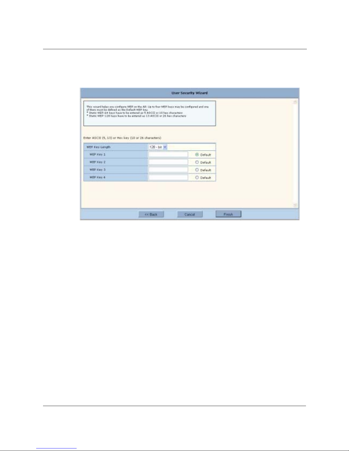
3 Using the Configuration Interfaces
48 Installation and Configuration Guide, (CQW-AP108AG)
To configure WEP:
1 Select Using WEP, and click Next to open the next User Security wizard panel (Figure 35).
Figure 35: User Security Wizard - WEP
2 Select the WEP key length.
3 Enter up to four WEP keys, and indicate which will be the default.
4 Click Finish.

Configuration Wizards
Installation and Configuration Guide, (CQW-AP108AG) 49
To configure open access:
1 Select Open Access, and click Next to open the next User Security wizard panel (Figure 36).
Figure 36: User Security Wizard - Open Access
2 Confirm that you want to configure the AP without user security.
3 Click Finish.

3 Using the Configuration Interfaces
50 Installation and Configuration Guide, (CQW-AP108AG)
Guest Access Wizard
The Guest Access wizard enables you to configure the network to give guest users limited access
while protecting the network from unauthorized use. For a complete description of guest access
rules and options, see Chapter 8, “Configuring Guest Access.”
To open the Guest Access wizard:
• Click Guest Access Wizard under AP Quick Start on the side menu.
The wizard (Figure 37) provides options to configure an internal landing page or an external
landing page for users who open a web browser while on site.
Figure 37: Guest Access Wizard

Configuration Wizards
Installation and Configuration Guide, (CQW-AP108AG) 51
To use an internal landing page:
1 In the Guest Access wizard, select Internal.
2 Click Next to open the next wizard panel.
3 Enter and confirm a guest password (Figure 38). The password must be from 1 to 63 characters
in length and may be manually distributed to guests who visit your corporate facility.
Figure 38: Guest Access Wizard - Internal Landing Page
4 Indicate whether the guest users will be able to access a subnet before they are authenticated as
guest users. If yes, enter the IP address of the subnet.
5 Click Next.

3 Using the Configuration Interfaces
52 Installation and Configuration Guide, (CQW-AP108AG)
6 Select an existing VLAN in which to place authenticated guest users, or create a new VLAN by
entering a numeric VLAN ID and VLAN name (Figure 39). The list of existing VLANS
includes only those that support open access.
Figure 39: Guest Access Wizard - VLAN Entry
7 Click Finish.
Guest access is now configured. When guests access the external landing page, they follow an
externally-determined process to log in to the network. If a subnet has been specified, then guests
can access the subnet even if they are not able to log in. For further information about guest access,
or to modify guest access parameters, see Chapter 7, “Managing Security.”

Configuration Wizards
Installation and Configuration Guide, (CQW-AP108AG) 53
To use an external landing page:
1 In the Guest Access wizard, select External.
2 Click Next to open the next wizard panel.
Figure 40: Guest Access Wizard - External Landing Page
3 Enter the full URL for the external landing page (Figure 39). The URL for the landing page
must use an IP address rather than a domain name. Regardless of the authentication process
selected for the external page, it is necessary to forward authentication results to the AP upon
completion of successful or unsuccessful guest authentication. The 108 Mbps Wireless Access
Point is shipped with an sample external landing page.
4 Enter the shared secret string that the AP will use to authenticate itself to the web server. The
code must be from 1 to 63 characters in length.
5 Indicate whether the guest users will be able to access a subnet before they are authenticated as
guest users. If yes, enter the IP address of the subnet.
6 Click Next.
7 Select an existing VLAN in which to place authenticated guest users, or create a new VLAN by
entering a numeric VLAN ID and VLAN name (Figure 39 on page 52). The list of existing
VLANS includes only those that support open access.
8 If desired, select a quality of service (QoS) level. Numeric QoS values range from 0 (lowest
priority) to 7 (highest priority).
9 Click Finish.
Guest access is now configured. When guests access the external landing page, they follow an
externally-determined process to log in to the network. If a subnet has been specified, then guests
can access the subnet even if they are not able to log in. For further information about guest access,
or to modify guest access parameters, see Chapter 7, “Managing Security.”

3 Using the Configuration Interfaces
54 Installation and Configuration Guide, (CQW-AP108AG)

Installation and Configuration Guide, (CQW-AP108AG) 55
4
Configuring Radio Settings
This chapter describes the configuration settings for the 108 Mbps Wireless Access Point radios
and explains how to set the configuration using the 108 Mbps Wireless AP web interface. It covers
all the features accessible from the Wireless Services menu except backhaul configuration, which is
discussed in Chapter 6. The chapter includes the following topics:
• Introduction
• Configuring Radio Parameters
• Setting the Advanced Radio Configuration
• Viewing Radio Statistics
• Viewing Radio Neighbor Details
• Configuring SSID Parameters
• Multiple SSIDs
• Configuring Inter Access Point Protocol (IAPP)
• Performing Radio Diagnostics
Introduction
The 108 Mbps Wireless Access Point can be configured with one or two radios, each of which
forms a distinct wireless cell or basic service set (BSS), as shown in Figure 41. Each radio can
operate in either of the following modes:
• In normal mode, the AP is connected to the wired network, and the radio directly services
downstream client stations or access points, or both. (AP mode).
• In wireless backhaul mode, the radio establishes a wireless link to a radio in AP mode on
another 108 Mbps Wireless AP in order to relay data through the wireless medium. The AP is
not attached to a wired connection, instead it is connected through the wireless medium to
another AP.
1
In this mode, the radio is called a Backhaul Point (BP mode). Wireless backhaul
is also known as a wireless distribution system (WDS).
1
Except in certain special configurations.

4 Configuring Radio Settings
56 Installation and Configuration Guide, (CQW-AP108AG)
Figure 41: AP Radios and Coverage
Use the Wireless Services items on the menu tree to access wireless parameters. The following
rules apply to the wireless settings:
• Some of the settings apply globally (for both radios); others apply on a per-radio basis.
• For configuration and reference purposes, the individual radios are labeled wlan0 and wlan1.
The wired Ethernet interface is labeled eth0.
• Some of the commands apply only to one mode (AP or BP).
• If the radio is in BP mode, parameters are stored and later applied if and when the radio takes
on the AP mode.
Each of the items in the Wireless Services menu leads to a specific area of radio configuration:
To open one of the Wireless Services panels, choose the topic from the menu tree.
Configuring Radio Parameters
Choose Radio Configuration from the Wireless Services menu to open the AP Radio
Configuration panel. The panel contains the following tabs:
• Global Configuration—Set parameters that apply to both of the AP radios.
• Persona Configuration—Set the radio mode or persona for normal (AP) operation or wireless
backhaul (BP).
Menu Item Description
Radio Configuration General radio parameters
Advanced Configuration 802.11 mode for each radio
Radio State & Statistics Detailed status and statistics for each radio
Radio Neighbors Identity of neighboring APs within beacon range
SSID Configuration Identification of the SSID parameters and assignment of service profiles
Backhaul Configuration Configuration of wireless backhaul links (See Chapter 6, “Configuring a
Wireless Backhaul.”)
Station Management List of stations associated to the 108 Mbps Wireless AP
IAPP Configuration Configuration of Inter-Access Point Protocol for roaming and load balancing
Radio Diagnostics Interface to perform link and walk tests
AP2 CellAP1 Cell
AP1
(Wired AP)
AP2
(Backhaul Point)
Wired Network
A0019A

Configuring Radio Parameters
Installation and Configuration Guide, (CQW-AP108AG) 57
• Channel Configuration—Configure channel usage for each radio.
• Performance—Configure enhanced data rates and performance attributes.
• Admission—Specify categories of client stations that are permitted to associate to the selected
radio.
To configure settings on these tabs, select each in sequence, or step through using the Go links at
the bottom of the panel (shown in Figure 42).
Many of the radio parameters are interdependent, and the 108 Mbps Wireless AP performs
consistency checks during configuration to prevent user actions from adversely affecting radio
performance. This is especially true of dual radio APs, due to the proximity of the two radios. If
you attempt to make configuration changes that are not accepted by the AP, an error message may
or may not appear. Consult the appropriate section in this chapter to determine which parameters
are in conflict.
Global Configuration
Use the Global Configuration tab (Figure 42) to define settings that apply to both of the 108 Mbps
Wireless AP radios.
NOTE: All the settings on this tab are optional. If the AP radio is enabled when the
global configuration is changed, then it is necessary to reset the AP for the changes to
take effect. If the radio is disabled, the changes take effect once the radio is enabled.

4 Configuring Radio Settings
58 Installation and Configuration Guide, (CQW-AP108AG)
Figure 42: Radio Configuration - Global Config
Set the following global parameters on this tab:
Field Description
Network Connectivity Specify the mode of connectivity to the wired network.
• The default value of Any means that the AP auto-determines whether or
not to initiate a backhaul based on the presence or absence of an active
Ethernet link. The Any setting is influenced by the number of radios in the
108 Mbps Wireless AP and whether or not the AP has active Ethernet
connectivity. If Any is selected, then the 108 Mbps Wireless AP is allowed
to change between wireless and wired mode based on a change in Ethernet
status.
• The Wired-Only setting means that the 108 Mbps Wireless AP operates
only as wired node. The node is disabled if the Ethernet link is not active.
All radios take on the AP persona unless explicitly configured as a BP
radio.
• The Wireless value means that the AP operates only as a wireless backhaul
node with wireless backhaul connectivity to the wired network. One radio
is automatically assigned the BP persona and one the AP persona. Applies
to dual radio APs only.
The default setting of Any is recommended.

Configuring Radio Parameters
Installation and Configuration Guide, (CQW-AP108AG) 59
Click Apply to save changes or Reset to return to previously saved values.
Network Density Set the wireless network density (low, medium, or high). Moving APs closer
to each other increases wireless capacity by providing higher data rates to
clients. To support this configuration, select the high density option. For
maximum coverage at lower data rates, use the low density setting. Each
setting determines the defer threshold parameters for the 108 Mbps Wireless
AP. The default is low; the default setting of “low” is appropriate for
maximum coverage.
World Mode - MultiDomain Support
Enables or disables 802.11d operation. If Enable is selected, the radio
advertises country, channel and associated maximum transmit power
information in beacons and probes responses to stations or clients in the BSS.
The default setting is enabled.
World Mode - Country
Code
Specify the country of operation of the AP. Select Default to set the channel
and power for the radio to the factory default country setting (U.S.).
Alternatively, enter a country code from the pull-down menu.
World Mode Deployment
Environment
Specify the type of environment in which the AP is installed (indoor, outdoor,
or both). Choosing the environment and country influences the channels of
operation that the AP or BP operate in or use for scanning and the maximum
radio transmit power. If the country or environment is changed, the following
occur:
• The channel selection setting is reset to auto-select channel at startup. To
configure a radio on a specific channel, apply the country configuration
and then specify the channel using the Channel Configuration tab (see
“Channel Configuration” on page 65).
• The channel set configuration is set to system determined band
configuration.
• All radios in the AP are reset.
For reference, Table 8 provides a list of world modes, including countries,
environments, bands, and valid channels.
AP Name in Beacon Confirm the AP node name advertised in beacons and probe responses. This is
the AP name that clients see when they scan for access points. The default is
the unique ID derived from the Ethernet MAC address of the AP. It is
recommended to accept the default setting. (required, AP radio only)
Background Scanning Enable or disable background scanning. Background scanning is performed to
collect interference and radio neighbor information from the surrounding RF
environment. If auto-select-channel is enabled with the Periodic option,
background scanning should also be enabled. See “Channel Configuration” on
page 65.
Field (continued) Description
Table 8:World Modes
Country Environment Band Valid Channel Numbers
USA Any 2.4 1,2,3,4,5,6,7,8,9,10,11
USA Indoor 2.4 1,2,3,4,5,6,7,8,9,10,11
USA Outdoor 2.4 1,2,3,4,5,6,7,8,9,10,11
USA Any 5 52,56,60,64,149,153,157,161
USA Indoor 5 36,40,44,48,52,56,60,64,149,153,157,161
USA Outdoor 5 52,56,60,64,149,153,157,161

4 Configuring Radio Settings
60 Installation and Configuration Guide, (CQW-AP108AG)
Mexico Any 2.4 1,2,3,4,5,6,7,8,9,10,11
Mexico Indoor 2.4 1,2,3,4,5,6,7,8,9,10,11
Mexico Outdoor 2.4 1,2,3,4,5,6,7,8,9,10,11
Mexico Any 5 149,153,157,161
Mexico Indoor 5 36,40,44,48,52,56,60,64,149,153,157,161
Mexico Outdoor 5 149,153,157,161
Argentina Any 2.4 1,2,3,4,5,6,7,8,9,10,11
Argentina Indoor 2.4 1,2,3,4,5,6,7,8,9,10,11
Argentina Outdoor 2.4 1,2,3,4,5,6,7,8,9,10,11
Argentina Any 5 52,56,60,64,149,153,157,161
Argentina Indoor 5 52,56,60,64,149,153,157,161
Argentina Outdoor 5 52,56,60,64,149,153,157,161
Brazil Any 2.4 1,2,3,4,5,6,7,8,9,10,11
Brazil Indoor 2.4 1,2,3,4,5,6,7,8,9,10,11
Brazil Outdoor 2.4 1,2,3,4,5,6,7,8,9,10,11
Brazil Any 5 149,153,157,161
Brazil Indoor 5 149,153,157,161
Brazil Outdoor 5 149,153,157,161
Countries listed under the leading Europe include major European countries not explicitly listed by name
in this table.
Europe Any 2.4 1,2,3,4,5,6,7,8,9,10,11,12,13
Europe Indoor 2.4 1,2,3,4,5,6,7,8,9,10,11,12,13
Europe Outdoor 2.4 1,2,3,4,5,6,7,8,9,10,11,12,13
Europe Any 5 100,104,108,112,116,120,124,128,132,126,140
Europe Indoor 5 36,40,44,48,52,56,60,64,100,104,108,112,116,120,124,128,132,
126,140
Europe Outdoor 5 100,104,108,112,116,120,124,128,132,126,140
France Any 2.4 9
France Indoor 2.4 9
France Outdoor 2.4 9
France Any 5 Not allowed
France Indoor 5 36,40,44,48,52,56,60,64
France Outdoor 5 9,10,11,12,13
Austria Any 2.4 1,2,3,4,5,6,7,8,9,10,11,12,13
Austria Indoor 2.4 1,2,3,4,5,6,7,8,9,10,11,12,13
Austria Outdoor 2.4 1,2,3,4,5,6,7,8,9,10,11,12,13
Austria Any 5 Not allowed
Austria Indoor 5 36,40,44,48,52,56,60,64
Austria Outdoor 5 Not Allowed
Table 8:World Modes (continued)
Country Environment Band Valid Channel Numbers

Configuring Radio Parameters
Installation and Configuration Guide, (CQW-AP108AG) 61
Belgium Any 2.4 1,2,3,4,5,6,7,8,9,10,11,12,13
Belgium Indoor 2.4 1,2,3,4,5,6,7,8,9,10,11,12,13
Belgium Outdoor 2.4 1,2,3,4,5,6,7,8,9,10,11,12,13
Belgium Any 5 Not allowed
Belgium Indoor 5 36,40,44,48,52,56,60,64
Belgium Outdoor 5 Not Allowed
Spain Any 2.4 10,11
Spain Indoor 2.4 10,11
Spain Indoor 2.4 10,11
Spain Any 5 100,104,108,112,116,120,124,128,132,126,140
Spain Indoor 5 36,40,44,48,52,56,60,64,100,104,108,112,116,120,124,128,132,
126,140
Spain Outdoor 5 100,104,108,112,116,120,124,128,132,126,140
Switzerland Any 2.4 1,2,3,4,5,6,7,8,9,10,11,12,13
Switzerland Indoor 2.4 1,2,3,4,5,6,7,8,9,10,11,12,13
Switzerland Outdoor 2.4 1,2,3,4,5,6,7,8,9,10,11,12,13
Switzerland Any 5 Not allowed
Switzerland Indoor 5 36,40,44,48
Switzerland Outdoor 5 Not Allowed
Japan Any 2.4 1,2,3,4,5,6,7,8,9,10,11,12,13,14
Japan Indoor 2.4 1,2,3,4,5,6,7,8,9,10,11,12,13,14
Japan Outdoor 2.4 1,2,3,4,5,6,7,8,9,10,11,12,13,14
Japan Any 5 34,38,42,46
Japan Indoor 5 34,38,42,46
Japan Outdoor 5 34,38,42,46
Singapore Any 2.4 9,10,11,12,13
Singapore Indoor 2.4 9,10,11,12,13
Singapore Outdoor 2.4 9,10,11,12,13
Singapore Any 5 52,56,60,64,149,153,157,161
Singapore Indoor 5 36,40,44,48,52,56,60,64,149,153,157,161
Singapore Outdoor 5 52,56,60,64,149,153,157,161
Israel Any 2.4 4,5,6,7,8,9
Israel Indoor 2.4 4,5,6,7,8,9
Israel Outdoor 2.4 4,5,6,7,8,9
Israel Any 5 52,56,60,64,149,153,157,161
Table 8:World Modes (continued)
Country Environment Band Valid Channel Numbers

4 Configuring Radio Settings
62 Installation and Configuration Guide, (CQW-AP108AG)
Israel Indoor 5 36,40,44,48,52,56,60,64,149,153,157,161
Israel Outdoor 5 52,56,60,64,149,153,157,161
Table 8:World Modes (continued)
Country Environment Band Valid Channel Numbers

Configuring Radio Parameters
Installation and Configuration Guide, (CQW-AP108AG) 63
Admin State Configuration
Use the Admin State tab (Figure 43) to assign the mode or persona of each radio interface.
Figure 43: Radio Configuration - Admin State
Set the following parameters on this tab:
Click Apply to save changes or Reset to return to previously saved values. Click Reset Radio to
Default to return the settings on all the radios to their factory defaults.
Feature Description
Select Radio Interface Select the AP radio (wlan0 or wlan1)
Admin State of Selected
Radio
Enable or disable the selected radio. When the AP radio is in the disabled
state, all valid configuration settings are saved. When the AP radio is enabled,
the latest configuration is applied. It is not possible to disable the BP radio by
administrative intervention. (AP radio only)
Persona of Selected
Radio
Select whether the AP radio is to operate as a normal AP (AP) or in backhaul
point mode (BP). Select Any to determine the radio mode automatically based
on network connectivity, configuration, number of radios, and presence of
Ethernet connectivity. It is recommended to accept the default setting of Any.
NOTE: Each access point can have at most one BP radio.

4 Configuring Radio Settings
64 Installation and Configuration Guide, (CQW-AP108AG)
Interdependencies
If Network Connectivity on the Radio Global tab (“Global Configuration” on page 57) is set to
Wireless, then at least one radio must have the BP or Any persona. If the Network Connectivity
setting is Wired or Any, then the personas of AP, BP, and Any are all permitted.
Table 9 shows how the Network Connectivity setting on the Global Configuration tab relates to the
Radio Persona Configuration on the Admin state tab.
Table 9: Radio Settings for Network Connectivity and Persona
Number of
Radios
Wired
Connection
a
a
Wired Connection means that the AP has Ethernet connectivity and that the connection is active.
Network
Connectivity
Setting Persona Setting Resulting radio persona or mode
One Yes Any Any or AP AP
One Yes Any BP BP
Two Yes Any All combinations
of Any and AP
Both radios AP
Two Yes Any All combinations
that specify a BP
radio
1 radio AP, 1 radio BP
Two No Any One radio set as BP1 radio AP, 1 radio BP
Two No Any Both radios AP Not permitted
One Yes Wired Any AP
Two Yes Wired All combinations
of Any and AP
Both radios AP
Two No Wireless All combinations
except both
radios AP
1 radio AP, 1 radio BP
Two No Wireless Both radios AP Not permitted

Configuring Radio Parameters
Installation and Configuration Guide, (CQW-AP108AG) 65
Channel Configuration
Use the Channel Configuration tab (Figure 44) to define rules for selecting radio channels. If two
radios are installed in the same AP, each radio operates in a different band (2.4 GHz for one radio
and 5 GHz for the other).
Figure 44: Radio Configuration - Channel Config
Set the following values in the Radio Interface Selection and Channel Configuration areas of the
tab:
Feature Description
Select Radio Interface Select the AP radio (wlan0 or wlan1).
Channel Number Select a valid channel for radio operation, or accept the Automatic Channel
Selection option.

4 Configuring Radio Settings
66 Installation and Configuration Guide, (CQW-AP108AG)
Click Apply to save changes or Reset to return to previously saved values. Click Force Select Best
Channel to trigger the channel selection algorithm for the AP radio, including a switch-over to a
better channel, if available. The Force Select Reselect Channel button applies only to the selected
AP radio interface.
Automatic channel
selection
Specify whether the channel is chosen when the AP is started, or whether it is
selected periodically. The time range for periodic channel selection is 30
minutes to 24 hours (1440 minutes). It is recommended to accept the default
setting of automatic channel selection of periodic at 30 minutes.
Channel Set Determine which channels the AP scans in order to determine the best channel
for operation. If Auto-Selection is enabled, this determines the channel set for
auto-selection. The following choices are available for channel set:
Band—Select a specific band, or the system-determined band option
(recommended).
• The System Determined Band setting means that the system chooses the
channel list or band for each radio based on the number of AP radios, the
persona of the radio, and the channel set of any second radio in the AP. If
the radio is in AP mode, then the node selects the best channel across both
bands. If the radio is in BP mode, then the BP radio scans on both bands.
• If the 108 Mbps Wireless AP is configured with two AP radios and AutoSelection is chosen for both, then the preferred band configuration for both
radios is System Determined. If both radios are in AP mode, then one
operates in the 2.4 GHz band and the other in the 5 GHz band.
• If the Channel Set is 2.4 or 5GHz, then the AP radio operates only in the
specified band. If it is set to 2.4 GHz, the AP chooses only nonoverlapping channels for operation (for example 1, 6, and 11). It is not
acceptable to set both radios to operate in the 2.4 GHz or 5GHz band.
• If both bands are selected, the AP radio chooses the best channel based on
the mode and band of the other radio on the AP (if installed).
• If a BP radio establishes a backhaul in the same band as the other AP radio,
this triggers the AP radio to change bands, provided that the AP radio is
configured for auto-selection and the system determined band.
Channel List—Enter a specific list of channels to be scanned, separated by a
single space (e.g.,1 2 6 11 13...). Overlapping channels can be specified in the
2.4 GHz band.
NOTE: World mode and environment settings influence the channel and channel set
configurations. See “Global Configuration” on page 57 for information on world
modes.
Feature (continued) Description

Configuring Radio Parameters
Installation and Configuration Guide, (CQW-AP108AG) 67
Performance
Use the Performance tab (Figure 45) to configure enhanced data rates of 72, 96, or 108 Mbps.
Figure 45: Radio Configuration - Performance
Set the following values on this tab:
Feature Description
Select Radio Interface Select the AP radio (wlan0 or wlan1)
Enhanced Data Rates Enable or disable the PLANEX enhanced data rates of (72, 96, and 108
Mbps). This setting is rejected if the enhanced Dot11 extensions are disabled
and an attempt is made to configure enhanced data rates. It is recommended to
accept the default of Enabled.
Rate Adaptation Enables or disables automatic data rate adaptation in the system. To use auto-
adaptation, select the Auto Adapt button and select the Basic or Advanced
option. Otherwise, select fixed along with a fixed rate. It is recommended to
accept the default value of Auto Adapt and Basic.

4 Configuring Radio Settings
68 Installation and Configuration Guide, (CQW-AP108AG)
Click Apply to save changes or Reset to return to previously saved values.
Interdependencies
Some restrictions apply to combinations of settings on the Channel Configuration and Performance
tabs.
• For fixed data rate configurations:
• If the configured channel is in the 5 GHz band or the Channel Set Band/List is 5 GHz,
System Determined, or Both, then at least one of the fixed rates must be other than an 11b
rate (1,2,5.5,or 11).
• If the configured channel is in the 2.4 GHz band or the Channel Set Band/List is 2.4 GHz
only, then only 11b/g rates are accepted.
• Assigning an enhanced rate (72, 96, and 108 Mbps), requires that the enhanced rates option
be enabled.
• To enable the Dot11 QoS settings on the Performance tab, you must enable the standard Dot-11
extensions on the 802.11 Policy tab (see “802.11 Policy” on page 70).
Ack Mode Determines the acknowledgement policy for data packets. The following
selections are available:
• Immediate Ack – Acknowledgement is sent for every packet received.
This is the default setting.
• No Ack – No acknowledgement is sent when data packets are received.
• To enable high performance, use this setting together with one of the
enhanced data rates.
• If this setting is used, then auto-adaptation cannot be enabled for the
selected radio. Only the fixed rate setting applies.
• This mode setting can be used for operations with PLANEX clients.
• Auto-ack – The acknowledgement policy is selected automatically based
on current link conditions.
Dot11 QoS Enables or disables 802.11e QoS. If enabled, the MAC mode is set to EDCF
or HCF. If disabled, then the MAC mode is DCF. It is recommended to accept
the default of Enabled.
Feature (continued) Description

Configuring Radio Parameters
Installation and Configuration Guide, (CQW-AP108AG) 69
Admission
Use the Admission tab (Figure 45) to specify categories of client stations that are permitted to
associate to the selected radio.
Figure 46: Radio Configuration - Admission
Set the following values on this tab:
Feature Description
Select Radio Interface Select the AP radio (wlan0 or wlan1).
802.11b-g STA
Admission Criteria Accept Association
from
Applies to the 2.4 Ghz band only. Specify the type of 802.11g or 802.11b and
g client stations permitted to associate. Selecting 802.11g-only keeps 802.11b
stations from degrading BSS performance. 802.11b and g is the default
setting.
Multi-Vendor STA
Admission Criteria Multi-Vendor Station
Accept allows all stations to associate; Reject restricts association to
compatible client stations, excluding non-compatible or non-PLANEX
stations.
Backhaul Admission
Criteria - Accept
Association From
Indicates whether to accept association from client stations, trunks or both:
STA or Trunk—Accept association from client stations or BP radios.
STA Only—Accept associations only from client stations.
Trunk Only—Accept associations only from BP radios.
Max Number of Trunks Determines the maximum number of trunks which are allowed to form with
the AP radio (range is 1-10). Default is 6.

4 Configuring Radio Settings
70 Installation and Configuration Guide, (CQW-AP108AG)
Setting the Advanced Radio Configuration
Select Advanced Configuration from the Wireless Services menu to open the Advanced
Configuration feature panel. The panel contains the following tabs:
• 802.11 Policy—Set the 802.11 modes for the AP radios.
• MAC Config—Set details of the radio beacon and MAC configuration for each radio.
To configure settings on these tabs, select each in sequence, or step through the tabs using the Go
links at the bottom of the panel (Figure 47).
802.11 Policy
Use the 802.11 tab(Figure 47) to set the 802.11 modes and data rates for each AP radio.
Figure 47: Advanced Configuration - 802.11 Policy
Set the following values on this panel:
Feature Description
Select Radio Interface Select the AP radio (wlan0 or wlan1).
IEEE 802.11 Mode in
2.4 Band
Select whether the radio is configured for 802.11b or 802.11g operation when
it operates in the 2.4 GHz band.

Setting the Advanced Radio Configuration
Installation and Configuration Guide, (CQW-AP108AG) 71
Click Apply to save changes or Reset to return to previously saved values.
IEEE 802.11 Extensions Indicate whether to support standard Dot11 extensions, enhanced extensions,
or both. The checkboxes enable or disable standard 802.11 extensions such as
11h, 11e, 11g or 11i, or PLANEX enhanced features, which are compatible
only with PLANEX client stations. If the Enhanced 802.11 extensions option
is selected, then it is possible to enable the following through the CLI (they are
not automatically enabled).
• Enhanced rate set (specific flag needs to be set)
• Proprietary burst ack
• Advanced rate adaptation
• Wireless backhaul AP name in beacon (if not enabled, the AP name in
beacon is suppressed)
802.11G Protection Select to enable 802.11g protection mode, short slot time, and short preamble
if the radio is operating in 802.11g mode.
If the checkbox is selected, all 3 aspects are enabled; if not, all 3 aspects are
disabled. The default setting is disabled.
Select Basic Rate Set Enter basic data rates for the different 802.11 modes. To set rates, select Set
and enter the rates with a space as the delimiter. The basic 802.11 rates are
advertised in beacons and inform the client stations of the minimum set of
rates it must support to be part of the BSS. 802.11 control frames such as
ACKS, CTS, and RTS are transmitted at basic rates.
Feature (continued) Description

4 Configuring Radio Settings
72 Installation and Configuration Guide, (CQW-AP108AG)
MAC Configuration
Use the MAC Configuration tab (Figure 48) under special circumstances if it is necessary to tune
low level operational parameters of the radio MAC (Medium Access Control) layer.
Figure 48: MAC Configuration Tab
NOTE: Changes on the MAC Configuration tab should only be made by trained
network personnel. The AP radio restarts automatically when these parameter changes
are applied.

Viewing Radio Statistics
Installation and Configuration Guide, (CQW-AP108AG) 73
Set the following parameters on the MAC Configuration tab:
Click Apply to save changes or Reset to return to previously saved values. The changes take effect
immediately if the radio is enabled.
Viewing Radio Statistics
Select Radio State & Statistics from the Wireless Services menu to view the current state of each
radio and the current communication statistics. This panel contains the following tabs:
• Radio State—View current configuration.
• Radio Statistics—View information about current operation.
Radio State
The Radio State tab (Figure 49) contains details on the current configuration and utilization of each
radio interface. The state information varies according to whether the radio is operating as a normal
access point radio (AP mode) or as a backhaul point (BP mode).
Field Description
Select Radio Interface Select the AP radio (required, wlan0 or wlan1).
Beacon Period Enter the desired interval between RF beacons, in milliseconds. It is
recommended to accept the default of 100 ms. (required).
DTIM (Delivery Traffic
Indication Message)
Period
Enter the interval between the times that the radio forwards multicast and
broadcast packets to client stations. It is recommended to accept the default of
1 beacon period. (required).
Fragmentation
Threshold
Enter the maximum packet size that can be transmitting as a single unit. A low
setting may be desirable in areas that have significant interference or poor
signal conditions. The range is 256-2346. It is recommended to accept the
default of 2000.
RTS Threshold Enter a packet size greater than which the AP issues a request-to-send (RTS)
message before sending the packet. Enter a low threshold if the ambient
conditions might make it relatively difficult for clients to associate to the AP.
The range is 0-2347. It is recommended to accept the default of 2347.
Short Retry Limit Enter a number of transmission retries (greater than or equal to data frame
MSDU size) after which a transmission is deemed a failure. The range is 1-
255.
Long Retry Limit Enter a number of transmission retries (greater than or equal to data frame
MSDU size) after which a transmission is deemed a failure. The range is 1-
255.

4 Configuring Radio Settings
74 Installation and Configuration Guide, (CQW-AP108AG)
Figure 49: Radio State Tab
Use the pull-down list to switch between radios. This tab contains the following information:
Field Description
Radio Persona Mode of the radio - AP or BP
Radio MAC Address MAC address of radio
Radio Admin State Administrative status of the radio (enabled or disabled)
Radio Operation State Operational status of the radio (enabled or disabled)
Operating Band Current band of operation

Viewing Radio Statistics
Installation and Configuration Guide, (CQW-AP108AG) 75
Current Channel
Number
Current channel of operation
Number of channel
changes
Number of times the channel has changed since boot-up (AP persona only)
Channel Change Cause Reason the frequency changed since boot-up, if appropriate, due to user
intervention or performance degradation (AP persona only)
Number of Associated
Stations
The number of stations that are associated to the radio (AP persona only)
Number of trunks Number of backhaul trunks associated with the radio (AP persona only)
Average Station Load Average load on client stations in percent (AP persona only)
Average Channel
Utilization
Average load on channels in percent (AP persona only)
Radio QoS Mode Mode used for class of service mapping
Load Balanced Number of stations that are load balanced (AP persona only)
CFP-Period Number of DTIM intervals between the start of Contention Free Periods
(CFPs).
CFP Max Duration Maximum duration of the CFP in time units that may be generated by the AP.
Privacy Option
Implemented
Security setting
Basic Rate Set Set of basic rates for BSS (AP persona only)
Operational Rate Set Set of operational rates for BSS
CCA mode supported List of all of the Clear Channel Assessment (CCA) modes supported by the
PHY
Current CCA mode current CCA method in operation
Temp Type Current physical operating temperature range capability.
Max Receive Lifetime Maximum MSDU receive lifetime
External antenna Indication of whether the radio has an external antenna (true) or not (false)
Interference Radio interference in the surrounding wireless environment pertaining to the
channel of operation, in dBm. (AP persona only)
Field (continued) Description

4 Configuring Radio Settings
76 Installation and Configuration Guide, (CQW-AP108AG)
Radio Statistics
The Radio Statistics tab (Figure 50) contains information on the operation of each radio. This
information varies according to whether the radio is in the AP or BP persona. The statistics refresh
every 10 seconds.
Figure 50: Radio Statistics Tab
Use the pull-down list to switch between radios. This tab contains the following information:
Field Description
Transmitted Fragment
Count
Number of transmitted fragments (MAC Protocol Data Units) that have been
acknowledged since last power-up or last Clear Statistics request
Transmitted Multicast
Frame Count
Number of transmitted multicast frames (MAC Service Data Units)
Failed Count Count of MSDU not transmitted successfully due to the number of transmit
attempts exceeding either the dot11ShortRetryLimit or dot11LongRetryLimit.
Received Fragment
Count
Count for successfully received MPDUs of type Data or Management.
Received Frame Count Count of successfully received frames (MSDUs)

Viewing Radio Statistics
Installation and Configuration Guide, (CQW-AP108AG) 77
FCS Error Count Count of FCS errors detected when receiving a MPDU.
Received Multicast
Frame Count
Count when a MSDU is received with the multicast bit set in the destination
MAC address.
Multiple Retry Count Count of successful transmissions after more than one retransmission.
Retry Count Count of successful transmissions after one or more retransmission
Frame Duplicate Count Count of frames received in which the Sequence Control field indicates it is a
duplicate frame.
Ack Failure Count Count of expected acks not received.
RTS Success Count Count of successful CTS received in response to a RTS
RTS Fail Count Count of RTS for which a CTS response is not received.
Transmitted Frame
Count
Count for successfully transmitted MSDUs.
WEP Undecryptable
Count
Number of times a frame is received with the WEP subfield of the Frame
Control field set to one and the WEPOn value for the key mapped to the
Transmitter MAC address indicates that the frame should not have been
encrypted or that frame is discarded due to the receiving STA not
implementing the privacy option. (Valid only if encryption is WEP)
# of transmitted Beacons Count of successfully transmitted beacons
Field (continued) Description

4 Configuring Radio Settings
78 Installation and Configuration Guide, (CQW-AP108AG)
Viewing Radio Neighbor Details
A radio neighbor is a radio whose beacon frame is detected by the AP. Select Radio Neighbors
from the Wireless Services menu to view summary information on all the neighboring APs within
beacon range (Figure 51).
Figure 51: Radio Neighbors
The summary table lists the following information:
Field Description
Interface The AP radio (wlan0 or wlan1)
BSSID The MAC address of the neighboring AP radio, which determines the BSS
SSID The name of the network (ESS) in which the AP is operating
BSS Type Infrastructure or ad-hoc network arrangement
Channel Current channel of operation for the neighboring BSS
AP Beacon Name Name of the neighboring AP in the beacon frame
Compatibility Status Indication of whether or not the neighbor is an AP with which the IAPP
protocol can be established
Strength Strength of Radio neighbor signal, in percent
Load percentage Load on the AP, in percent
STA Count Number of client stations served by the neighboring AP

Configuring SSID Parameters
Installation and Configuration Guide, (CQW-AP108AG) 79
Use the scrolling bars to display the full range of interfaces and data.
Configuring SSID Parameters
A wireless network is formed when a set of APs advertises the same value as the SSID, or network
name. Figure 52 shows the Acme Works network with multiple 108 Mbps Wireless APs, each
advertising the same “Corporate” SSID.
Figure 52: Example “Corporate” Network
Each 108 Mbps Wireless AP is shipped with a default SSID, which must be replaced during the
bootstrap process (see “Using AP Quick Start to Initialize the Access Point” on page 31) or from
the SSID Configuration panel, as explained in this section. Multiple SSIDs are also supported.
“Multiple SSIDs” on page 86 explains how to enable this feature and permit clients to access
multiple wireless networks through the same access point.
A0042D
SSID="Corp"
SSID="Corp"
10/100 Switched Ethernet

4 Configuring Radio Settings
80 Installation and Configuration Guide, (CQW-AP108AG)
SSIDs and Service Profiles
A service profile consists of VLAN, COS, and minimal security attributes applied to a network or
to designated classes of users once they are authenticated by a RADIUS authentication server
(security portal or external authentication server). If the service profile is defined without reference
to a specific user group and bound to an SSID, then the profile is applied to all users who access the
network.
Figure 53 illustrates the relationship between users, user groups, service profiles, and SSID. A
RADIUS authentication server stores user group information and uses that information to match
users to groups during authentication. Upon authentication, a previously-defined service profile is
assigned to the user based on user group membership. The service profile, in turn, is bound to the
SSID and thereby determines level of service awarded to the user.
Figure 53: SSIDs and Service Profiles
From the SSID Configuration panels, you can define service profiles for user groups and then bind
the profiles to the SSID. A user who requests access to the network is authenticated and placed into
the appropriate user group, and the AP software automatically applies the privileges and
restrictions defined in the service profile for that group. Each user group can be assigned to just one
service profile, but multiple groups can share the same service profile.
Select SSID Configuration from the Wireless Services menu to open the SSID Configuration
panel. The panel contains the following tabs:
• SSID Table—View the current SSID configuration, modify the configuration, or add new
SSIDs.
• SSID Details—View the association between SSIDs and service profiles.
• Profile Table—Manage service profiles.
• Multiple SSID—Enable the multiple SSID feature.
NOTE: The SSID settings in this section apply only to AP mode radios. The Backhaul
Configuration panel described in “Configuring a Wireless Backhaul” on page 129 is
used to configure the SSID for the BP radio. Make sure that the SSID configuration for
the AP matches that of the other APs in the network.
A0029
User Groups
Assigned to Service Profile
VLAN
QOS
Encryption
Bound to
SSID
Users
Members of
Users

Configuring SSID Parameters
Installation and Configuration Guide, (CQW-AP108AG) 81
SSID Table
Select SSID Configuration from the Wireless Services menu to open the SSID Table (Figure 54).
Figure 54: SSID Configuration - SSID Table
The table lists the following information about each SSID:
Field Description
SSID Name Name (maximum 32 alphanumeric characters). This name is used only by
the radio in AP mode, and is broadcast in its beacon. For a radio in
backhaul point mode, the SSID name is entered in the Backhaul
Configuration, Link Criteria tab (see Chapter 6).
Max stations The maximum number of stations that can be associated to this SSID on this
AP. The range is 1-512.
If the maximum number of stations is reached
and a new client tries to associate to the AP, the association attempt is
rejected. Association is also rejected if the number of clients is less
than the maximum but exceeds the number of client stations permitted
by the AP license.
Auth Zone The RADIUS authentication zone for the SSID
PSK-Type The type of pre-shared key used, if WPA is the encryption suite
MAC-ACL MAC-ACL authentication enabled or disabled
Auth Servers The RADIUS server used for user authentication

4 Configuring Radio Settings
82 Installation and Configuration Guide, (CQW-AP108AG)
Follow these steps to rename the SSID or modify its configuration:
1 Click Modify to open the SSID Details table, which also provides access to service profiles for
the SSID.
2 Enter the new SSID name.
3 Click Apply. If an SSID is renamed, all configuration details related to the old SSID name,
such as service profile associations and security configuration, are automatically transferred,
and the radios that operate in AP mode now broadcast the new SSID in the beacon.
The default SSID cannot be modified. If an attempt is made to modify the default SSID, the system
prompts you to first rename it. If you select the current SSID in the table and click Delete, the SSID
reverts to the default.
The 108 Mbps Wireless AP can be configured to support multiple SSIDs. If this feature is enabled
on the Multiple SSID tab (“Multiple SSIDs” on page 86), then it is possible to add new SSIDs from
the SSID Table tab, in addition to modifying or deleting an existing SSID.
Perform the following functions on the SSID Table tab:
Function Description
Add new SSID (if multiple
SSID is enabled)
1 Click Add and enter the following information:
• SSID name—This name is used only by the radio in AP mode. For
a radio in backhaul point mode, enter the SSID name in the
Backhaul Configuration, Link Criteria tab (see Chapter 6).
• Max Number of Stations—Enter a maximum number of clients
stations, if desired. The range of values is 1-512. If the maximum
number of stations is reached and a new client tries to associate to
the AP, the association attempt is rejected. Association is also
rejected if the number of clients is less than the maximum but
exceeds the number of client stations permitted by the AP license.
2 Click Apply.
Modify an existing SSID 1 Select the SSID and click Modify to open the SSID Details table,
which also provides access to service profiles for the SSID.
2 Enter the new SSID name.
3 Confirm the maximum number of stations
4 Click Apply.
Delete an SSID (if multiple
SSID is enabled)
Click Delete, and click OK to confirm.
Change the SSID broadcast
setting (single SSID
configurations only)
For single SSID configurations, the SSID Table tab provides the option to
broadcast the SSID in the AP beacon, or to suppress broadcast of the
SSID for increased security. The SSID is never broadcast in multiple
SSID configurations.
To change the SSID broadcast setting:
1 Select no or yes.
2 Click Apply.

Configuring SSID Parameters
Installation and Configuration Guide, (CQW-AP108AG) 83
SSID Details
Use the SSID Details Tab (Figure 55) to modify an SSID and bind service profiles to an SSID.
Figure 55: SSID Configuration - SSID Details
The tab contains two areas. Use the Modify SSID Configuration area to change the current SSID
configuration, as described in “SSID Table” on page 81. The bottom area shows the service profiles
currently bound to the SSID. This list includes the following information for each service profile:
Feature Description
User Group User group linked to the service profile. If this entry is empty, the user group
is null. The null user group is automatically assigned to the default service
profile, unless it is explicitly bound to another service profile. RADIUS
authentication must be active in order for user groups to be effective. The user
group for a given client is passed to the AP as a RADIUS attribute for each
successfully-authenticated user. To edit the group information, click the group
name link. Any attempt to delete the null user group, automatically associates
it to the default service profile.
Profile Service profile name.
VLAN VLAN assigned to the service profile.
COS Class of service values assigned to the service profile.

4 Configuring Radio Settings
84 Installation and Configuration Guide, (CQW-AP108AG)
Perform the following functions from the service profile list on this tab:
Figure 56: SSID Configuration - Bind Service Profile to SSID
Security Enforcement Type of encryption required for the service profile. For user groups assigned
to this service profile, the security enforcement setting supersedes the
encryption type configured for the overall network.
Function Steps
Bind an existing service
profile to an SSID
1 Click Add to open the Bind Service Profile to SSID entry panel
(Figure 56).
2 Select the profile name, or click Add New Profile to create a new
profile according to the instructions in “Profile Table” on page 85.
3 Select a group name from the existing RADIUS group names to
associate with the profile, or select New Group and enter a new user
group name.
4 Click Apply.
Change service profile
binding
1 Select the checkbox for the user group and profile, and click Modify
to open the Bind Service Profile to SSID entry panel (Figure 56) in
modify mode.
2 Select a profile to bind to the SSID, or click Add New Profile to
create a new profile according to the instructions in “Profile Table” on
page 85.
3 Click Apply.
Delete service profile binding 1 Select the checkbox for the user group and profile, and click Delete.
2 Click OK to confirm.
Configure security for the
SSID
Click Go at the bottom of the panel. The button leads to the SSID
Authentication tab of the Wireless Security panel. For instructions on
defining the security settings, refer to “SSID Authentication” on
page 142. After defining the security settings, click Back on the browser
to return to the SSID Details tab.
Feature (continued) Description

Configuring SSID Parameters
Installation and Configuration Guide, (CQW-AP108AG) 85
Profile Table
The Profile Table tab (Figure 57) lists all the currently defined service profiles. Each service profile
includes attributes for security enforcement, VLAN ID, and COS value. Binding a service profile to
an SSID determines the privileges and restrictions that apply to user groups associated with the
profile.
Figure 57: SSID Configuration - Profile Table
NOTE: Changes made to SSID or service profiles cause affected users to be
automatically disassociated from the AP. The AP then attempts to reassociate them
automatically. This causes a momentary interruption in service.

4 Configuring Radio Settings
86 Installation and Configuration Guide, (CQW-AP108AG)
Perform the following functions from this tab:
Multiple SSIDs
With the multiple SSID feature, the same physical network infrastructure can support multiple
wireless networks. Each network (identified by SSID) can have its own service profile and
associated level of service. For example, Figure 58 shows how Acme Works configured two
SSIDs: one to accommodate the normal corporate network and one for a separate video conference
network, which requires a higher quality of service.
Figure 58: Example Use of Multiple SSIDs to Differentiate Levels of Service
Function Steps
Add a new service
profile
1 Click Add to create a new service profile.
2 Enter the profile name, which must be unique. (required)
3 Select the VLAN for the profile.
4 Enter a COS value for the profile. The range is 0-7. For more information,
see “Configuring Quality of Service” on page 113.
5 Select an enforcement level for data encryption to apply to the profile. This
setting provides fine-grained security options at the user group level.
Default-enforcement refers to the encryption settings that prevail in the
network at large. The security enforcement applies after authentication is
complete.
6 Enter a description, if desired.
7 Click Apply to save the profile or Cancel to return to the Profile Table.
Modify a profile 1 Select the profile from the table and click Modify.
2 Make changes as desired, and click Apply, or click Cancel to return to the
Profile Table without saving changes. User groups bound to the profile
automatically inherit any modified attributes.
It is not possible to modify the default profile.
Delete a profile A service profile can only be deleted if there are no groups under the SSID
bound to the profile. It is not possible to delete the default profile.
A0043B
SSID="Corporate" SSID="Video"
10/100 Switched Ethernet
Corporate Video
COS=7COS=4

Managing Client Stations
Installation and Configuration Guide, (CQW-AP108AG) 87
Use the Multiple SSID tab (Figure 59) to enable the multiple SSID feature. Make a selection, and
click Apply. After enabling the multiple SSID feature, additional SSIDs can be added on the SSID
Table (see “SSID Table” on page 81).
When multiple SSIDs are enabled on the 108 Mbps Wireless AP, that AP no longer broadcasts an
SSID in its beacon frame. In order for a client to associate with the 108 Mbps Wireless AP
configured for multiple SSIDs, a profile for each target SSID must be created on the client
workstation using the Windows Zero Config (WZC) Add function or the PLANEX Client Utility
Create function.
Figure 59: SSID Configuration - Multiple SSID
Managing Client Stations
Select Station Management from the Wireless Services menu to open the Station Associations
panel. The panel contains the following tabs:
• Stations—View all client stations associated to this 108 Mbps Wireless AP.
• Link Stat—View signal strength, signal quality and all the MAC level statistics.
• Security Stat—View 802.1x security statistics.
 Loading...