

Page 1

11g
Wireles s
B roadband
R outer
802.11g/802.11b W ireles s A cces s Poin t
B roadband Internet Acces s
4-Port S witching Hub
Us er's G uide
Page 2

Regulatory Approvals
FCC Statement
This equipment has been tested and found to comply with the limits for a Class B digital
device, pursuant to Part 15 of the FCC Rules. These limits are designed to provide reasonable
protection against harmful interference in a residential installation.
This equipment generates, uses and can radiate radio frequency energy and, if not installed and
used in accordance with the instructions, may cause harmful interference to radio communications. However, there is no guarantee that interference will not occur in a particular installation.
If this equipment does cause harmful interference to radio or television reception, which can be
determined by turning the equipment off and on, the user is encouraged to try to correct the
interference by one of the following measures:
Reorient or relocate the receiving antenna.
Increase the separation between the equipment and receiver.
Connect the equipment into an outlet on a circuit different from that to which the receiver
is connected.
Consult the dealer or an experienced radio/TV technician for help.
To assure continued compliance, any changes or modifications not expressly approved by the
party responsible for compliance could void the user's authority to operate this equipment.
(Example - use only shielded interface cables when connecting to computer or peripheral
devices).
FCC Radiation Exposure Statement
This equipment complies with FCC RF radiation exposure limits set forth for an uncontrolled
environment. This equipment should be installed and operated with a minimum distance of 20
centimeters between the radiator and your body.
This device complies with Part 15 of the FCC Rules. Operation is subject to the following two
conditions:
(1) This device may not cause harmful interference, and
(2) This device must accept any interference received, including interference that may cause
undesired operation.
This transmitter must not be co-located or operating in conjunction with any other antenna or
transmitter.
The antennas used for this transmitter must be installed to provide a separation distance of at
least 20 cm from all persons and must not be co-located or operating in conjunction with any
other antenna or transmitter.
Channel
The Wireless Channel sets the radio frequency used for communication.
•Access Points use a fixed Channel. You can select the Channel used. This allows you to
choose a Channel which provides the least interference and best performance. In the USA
and Canada, 11 channel are available. If using multiple Access Points, it is better if adjacent
Access Points use different Channels to reduce interference.
• In "Infrastructure" mode, Wireless Stations normally scan all Channels, looking for an
Access Point. If more than one Access Point can be used, the one with the strongest
signal is used. (This can only happen within an ESS.)
• If using "Ad-hoc" mode (no Access Point), all Wireless stations should be set to use the
same Channel. However, most Wireless stations will still scan all Channels to see if there
is an existing "Ad-hoc" group they can join.
Note:This equipment marketed in USA is restricted by firmware to only operate on 2.4G channel 1-11
.
Page 3

i
Table of Contents
CHAPTER 1 INTRODUCTION.............................................................................................. 1
Wireless Router Features.................................................................................................. 1
Package Contents ..............................................................................................................3
Physical Details.................................................................................................................. 4
CHAPTER 2 INSTALLATION...............................................................................................6
Requirements..................................................................................................................... 6
Procedure...........................................................................................................................6
CHAPTER 3 SETUP.................................................................................................................8
Overview ............................................................................................................................8
Configuration Program..................................................................................................... 9
Setup Wizard ................................................................................................................... 11
LAN Screen...................................................................................................................... 14
Wireless Screen................................................................................................................16
Password Screen.............................................................................................................. 22
CHAPTER 4 PC CONFIGURATION...................................................................................23
Overview ..........................................................................................................................23
Windows Clients.............................................................................................................. 23
Macintosh Clients............................................................................................................ 35
Linux Clients....................................................................................................................35
Other Unix Systems.........................................................................................................35
Wireless Station Configuration ......................................................................................36
CHAPTER 5 OPERATION AND STATUS .........................................................................37
Operation .........................................................................................................................37
Status Screen....................................................................................................................37
Connection Status - PPPoE............................................................................................. 39
Connection Status - PPTP............................................................................................... 42
Connection Status - L2TP...............................................................................................43
Connection Status - Telstra Big Pond............................................................................44
Connection Details - SingTel RAS..................................................................................45
Connection Details - Fixed/Dynamic IP Address..........................................................47
CHAPTER 6 ADVANCED FEATURES...............................................................................49
Overview ..........................................................................................................................49
Access Control ................................................................................................................. 49
Dynamic DNS (Domain Name Server)...........................................................................54
Advanced Internet Screen...............................................................................................56
URL Filter........................................................................................................................ 60
Define Schedule................................................................................................................62
User Groups.....................................................................................................................63
Virtual Servers.................................................................................................................64
WAN Port Configuration................................................................................................ 68
CHAPTER 7 ADVANCED ADMINISTRATION................................................................72
Overview ..........................................................................................................................72
Config File........................................................................................................................ 73
Logs...................................................................................................................................74
Network Diagnostics........................................................................................................76
Options .............................................................................................................................77
PC Database.....................................................................................................................78
Remote Administration...................................................................................................82
Page 4

ii
Routing.............................................................................................................................84
Security.............................................................................................................................88
Upgrade Firmware.......................................................................................................... 90
APPENDIX A TROUBLESHOOTING ................................................................................91
Overview ..........................................................................................................................91
General Problems............................................................................................................ 91
Internet Access.................................................................................................................91
APPENDIX B ABOUT WIRELESS LANS .......................................................................... 93
Modes ...............................................................................................................................93
BSS/ESS............................................................................................................................93
Channels........................................................................................................................... 94
WEP..................................................................................................................................94
WPA..................................................................................................................................94
WPA2................................................................................................................................95
WPA+WPA2....................................................................................................................95
Wireless LAN Configuration..........................................................................................95
APPENDIX C SPECIFICATIONS........................................................................................ 97
Multi-Function Wireless Router ....................................................................................97
Wireless Interface............................................................................................................97
Regulatory Approvals .....................................................................................................98
P/N: 9560MZ0101
Copyright ! 2004. All Rights Reserved.
Document Version: 1.96 (September, 2005)
All trademarks and trade names are the properties of their respective owners.
Page 5
1
Chapter 1
Introduction
This Chapter provides an overview of the Wireless Router's features and capabilities.
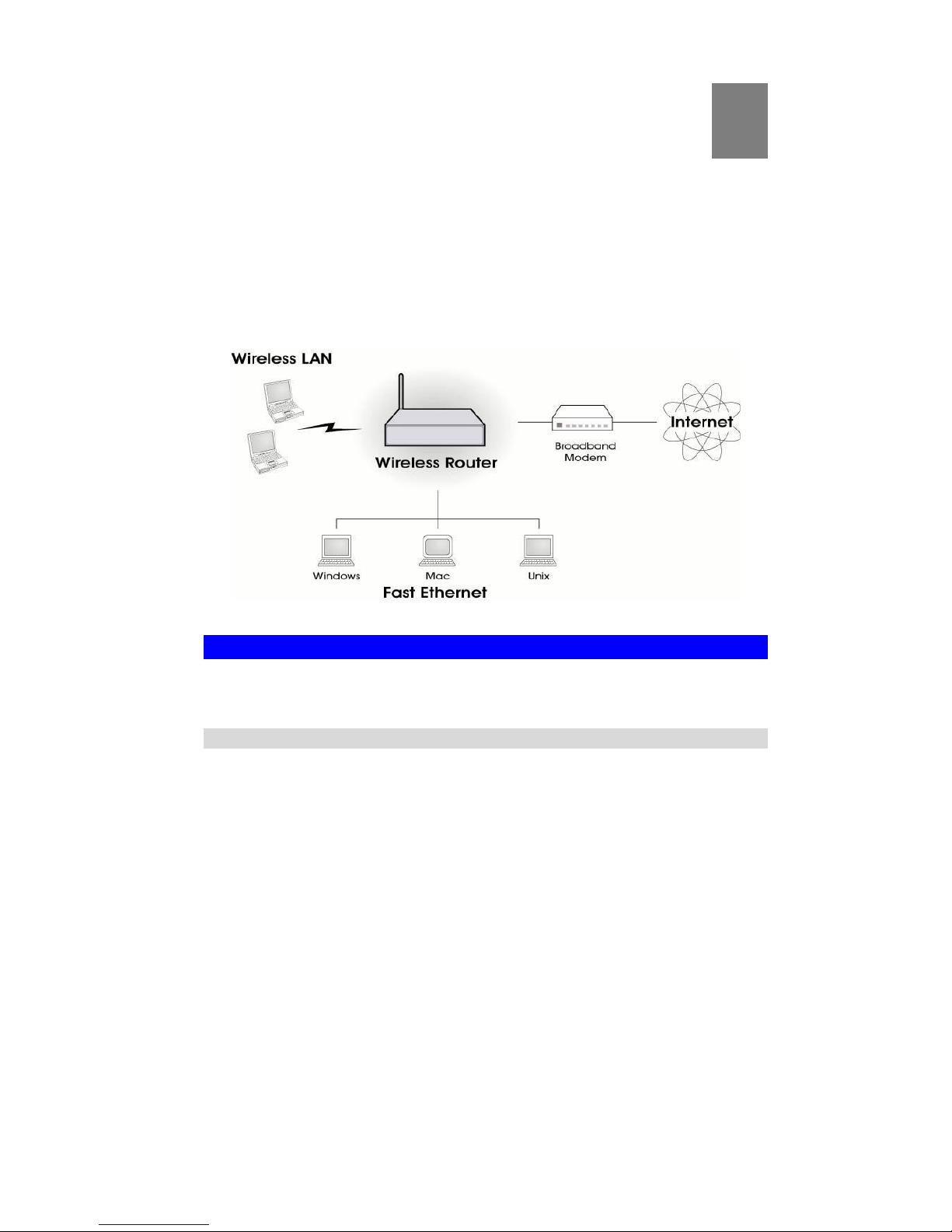
Congratulations on the purchase of your new Wireless Router. The Wireless Router is a multifunction device providing the following services:
" Shared Broadband Internet Access for all LAN users.
" 4-Port Switching Hub for 10BaseT or 100BaseT connections.
" Wireless Access Point for 802.11b and 802.11g Wireless Stations.
Figure 1: Wireless Router
Wireless Router Features
The Wireless Router incorporates many advanced features, carefully designed to provide
sophisticated functions while being easy to use.
Internet Access Features
" Shared Internet Access. All users on the LAN or WLAN can access the Internet
through the Wireless Router, using only a single external IP Address. The local (invalid) IP
Addresses are hidden from external sources. This process is called NAT (Network Address
Translation).
" DSL & Cable Modem Support. The Wireless Router has a 10/100BaseT Ethernet port
for connecting a DSL or Cable Modem. All popular DSL and Cable Modems are supported. SingTel RAS and Big Pond (Australia) login support is also included.
" PPPoE, PPTP, SingTel RAS and Telstra Big Pond Support. The Internet (WAN
port) connection supports PPPoE (PPP over Ethernet), PPTP (Peer-to-Peer Tunneling Protocol), SingTel RAS and Telstra Big Pond (Australia), as well as "Direct Connection" type
services. Unnumbered IP with PPPoE is also supported.
" Fixed or Dynamic IP Address. On the Internet (WAN port) connection, the Wireless
Router supports both Dynamic IP Address (IP Address is allocated on connection) and
Fixed IP Address.
1
Page 6

Wireless Router User Guide
2
Advanced Internet Functions
" Communication Applications. Support for Internet communication applications, such
as interactive Games, Telephony, and Conferencing applications, which are often difficult
to use when behind a Firewall, is included.
" Special Internet Applications. Applications which use non-standard connections or
port numbers are normally blocked by the Firewall. The ability to define and allow such
applications is provided, to enable such applications to be used normally.
" Virtual Servers. This feature allows Internet users to access Internet servers on your
LAN. The required setup is quick and easy.
" DDNS Support. DDNS (Dynamic DNS) allows Internet users to connect to Virtual
Servers on your LAN using a domain name, even if your IP address is not fixed.
" Multi-DMZ. For each WAN (Internet) IP address allocated to you, one (1) PC on your
local LAN can be configured to allow unrestricted 2-way communication with Servers or
individual users on the Internet. This provides the ability to run programs which are incompatible with Firewalls.
" URL Filter. Use the URL Filter to block access to undesirable Web sites by LAN users.
" Internet Access Log. See which Internet connections have been made.
" Access Control. Using the Access Control feature, you can assign LAN users to different
groups, and determine which Internet services are available to each group.
" VPN Pass through Support. PCs with VPN (Virtual Private Networking) software
using PPTP, L2TP and IPSec are transparently supported - no configuration is required.
Wireless Features
" Standards Compliant. The Wireless Router complies with the IEEE802.11g (DSSS)
specifications for Wireless LANs.
" Supports both 802.11b and 802.11g Wireless Stations. The 802.11g standard
provides for backward compatibility with the 802.11b standard, so both 802.11b and
802.11g Wireless stations can be used simultaneously.
" Speeds to 54Mbps. All speeds up to the 802.11g maximum of 54Mbps are supported.
" WEP support. Support for WEP (Wired Equivalent Privacy) is included. Key sizes of 64
Bit and 128 Bit are supported.
" WPA support. The WPA-PSK (Pre-shared Key) standard provides greater security for
your Wireless clients than WEP.
" WPA2 support. The WPA2 (Pre-shared Key) standard, a later version of WPA which
offers improved security. AES encryption is always used.
" WPA+WPA2 support. If selected, wireless clients may use either WPA or WPA2. This
option is sometimes called "Mixed Mode".
" Wireless MAC-level Access Control. The Wireless Access Control feature can check
the MAC address (hardware address) of Wireless stations to ensure that only trusted Wireless Stations can access your LAN.
" Simple Configuration. If the default settings are unsuitable, they can be changed
quickly and easily.
LAN Features
" 4-Port Switching Hub. The Wireless Router incorporates a 4-port 10/100BaseT switch-
ing hub, making it easy to create or extend your LAN.
Page 7

Introduction
3
" DHCP Server Support. Dynamic Host Configuration Protocol provides a dynamic IP
address to PCs and other devices upon request. The Wireless Router can act as a DHCP
Server for devices on your local LAN and WLAN.
" Multi Segment LAN Support. LANs containing one or more segments are supported;
via the Wireless Router's RIP (Routing Information Protocol) support and built-in static
routing table.
Configuration & Management
" Easy Setup. Use your WEB browser from anywhere on the LAN or WLAN for configu-
ration.
" Configuration File Upload/Download. Save (download) the configuration data from
the Wireless Router to your PC and restore (upload) a previously-saved configuration file
to the Wireless Router.
" Remote Management. The Wireless Router can be managed from any PC on your LAN.
And, if the Internet connection exists, it can also (optionally) be configured via the Internet.
" Network Diagnostics. You can use the Wireless Router to perform a Ping or DNS
lookup.
" UPnP Support. UPnP (Universal Plug and Play) allows automatic discovery and con-
figuration of the Wireless Router. UPnP is by supported by Windows ME, XP, or later.
Security Features
" Password - protected Configuration. Optional password protection is provided to
prevent unauthorized users from modifying the configuration data and settings.
" Wireless LAN Security. WPA-PSK and WEP (Wired Equivalent Privacy) are sup-
ported, as well as MAC-level Wireless access control to prevent unknown wireless stations
from accessing your LAN.
" NAT Protection. An intrinsic side effect of NAT (Network Address Translation) tech-
nology is that by allowing all LAN users to share a single IP address, the location and even
the existence of each PC is hidden. From the external viewpoint, there is no network, only
a single device - the Wireless Router.
" Stateful Inspection Firewall. All incoming data packets are monitored and all incom-
ing server requests are filtered, thus protecting your network from malicious attacks from
external sources.
" Protection against DoS attacks. DoS (Denial of Service) attacks can flood your
Internet connection with invalid packets and connection requests, using so much bandwidth
and so many resources that Internet access becomes unavailable. The Wireless Router incorporates protection against DoS attacks.
Package Contents
The following items should be included:
" The Wireless Router Unit
" Power Adapter
" Quick Installation Guide
" CD-ROM containing the on-line manual.
If any of the above items are damaged or missing, please contact your dealer immediately.
Page 8
Wireless Router User Guide
4
Physical Details
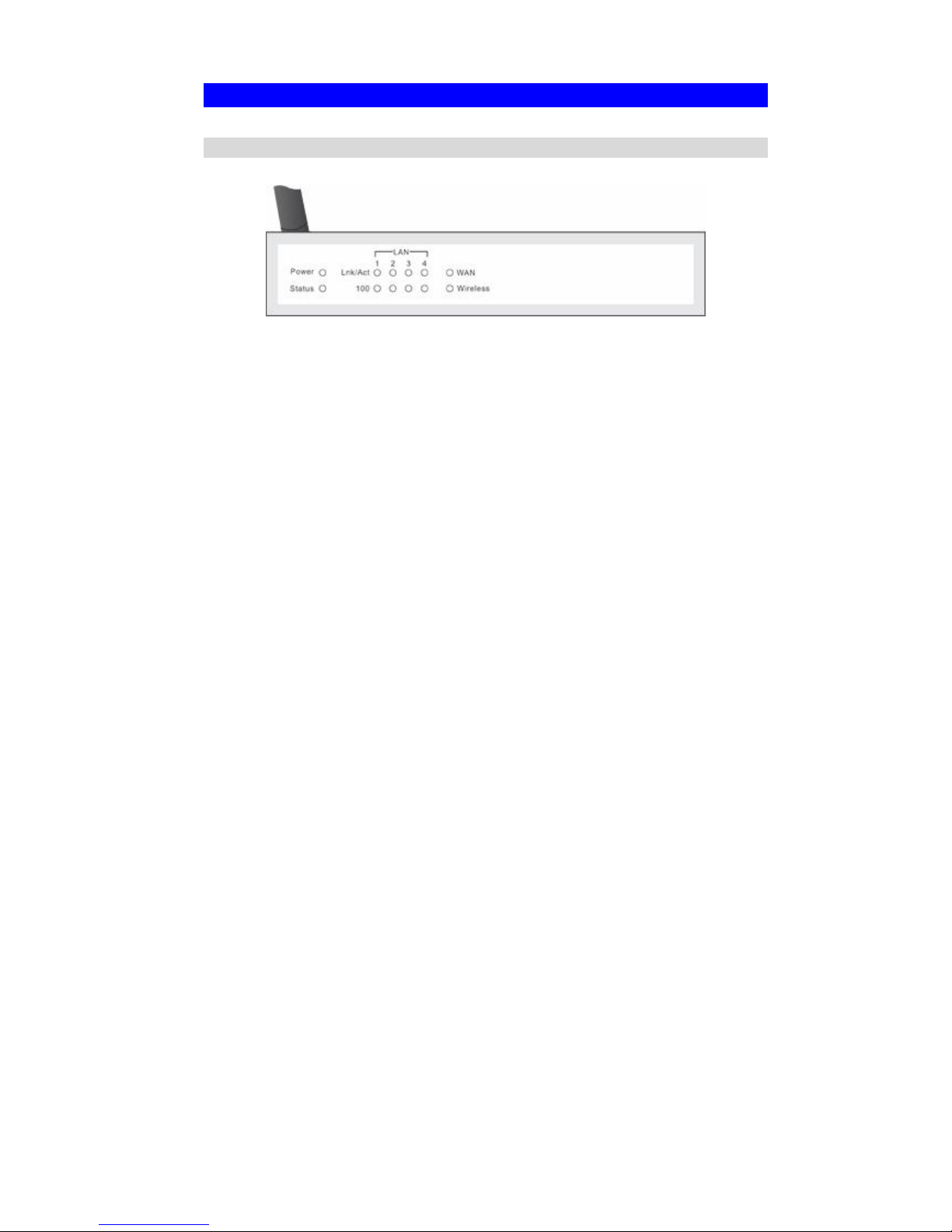
Front-mounted LEDs
Figure 2: Front Panel
Power LED On - Power on.
Off - No power.
Status (Red)
LED
On - Error condition.
Off - Normal operation.
Blinking - This LED blinks during start up, and during a Firmware Up-
grade.
LAN LEDs
For each port, there are 2 LEDs
" Link/Act
" On - Corresponding LAN (hub) port is active.
" Off - No active connection on the corresponding LAN (hub) port.
" Flashing - Data is being transmitted or received via the corre-
sponding LAN (hub) port.
" 100
" On - Corresponding LAN (hub) port is using 100BaseT.
" Off - Corresponding LAN (hub) port connection is using
10BaseT, or no active connection.
WAN LED On - Connection to the Broadband Modem attached to the WAN (Internet)
port is established.
Off - No connection to the Broadband Modem.
Flashing - Data is being transmitted or received via the WAN port.
Wireless LED On - Wireless connection available; Wireless Access Point is ready for
use.
Off - No Wireless connection available.
Flashing - Data is being transmitted or received via the Wireless access
point. Data includes "network traffic" as well as user data.
Page 9
Introduction
5
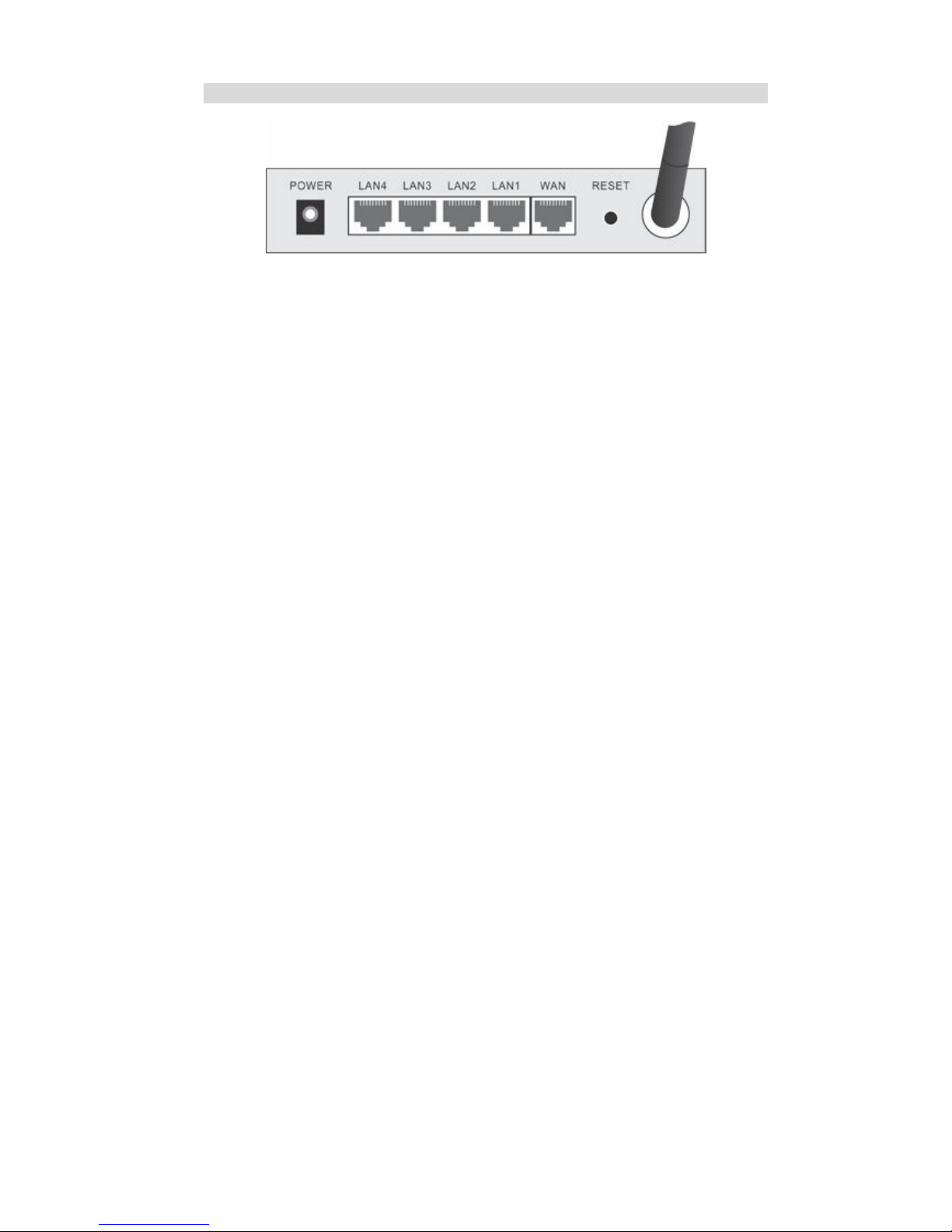
Rear Panel
Figure 3: Rear Panel
Power port
Connect the supplied power adapter here.
10/100BaseT
LAN connections
Use standard LAN cables (RJ45 connectors) to connect your PCs to
these ports.
If required, any port can be connected to another hub. Any LAN port
will automatically function as an "Uplink" port when necessary.
WAN port
(10/100BaseT)
Connect the DSL or Cable Modem here. If your modem came with a
cable, use the supplied cable. Otherwise, use a standard LAN cable.
Reset Button
This button has two (2) functions:
" Reboot. When pressed and released, the Wireless Router will
reboot (restart).
" Clear All Data. This button can also be used to clear ALL data
and restore ALL settings to the factory default values.
To Clear All Data and restore the factory default values:
1. Power Off.
2. Hold the Reset Button down while you Power On.
3. Keep holding the Reset Button for a few seconds, until the RED
LED has flashed TWICE.
4. Release the Reset Button. The Wireless Router is now using the
factory default values.
Antenna
If the antenna is detachable, connect it here. When in use, best results
are usually obtained with the antenna in an upright position.
Page 10
6
Chapter 2
Installation
This Chapter covers the physical installation of the Wireless Router.
Requirements
" Network cables. Use standard 10/100BaseT network (UTP) cables with RJ45 connectors.
" TCP/IP protocol must be installed on all PCs.
" For Internet Access, an Internet Access account with an ISP, and either of a DSL or Cable
modem (for WAN port usage)
" To use the Wireless Access Point, all Wireless devices must be compliant with the
IEEE802.11b or IEEE802.11g specifications.
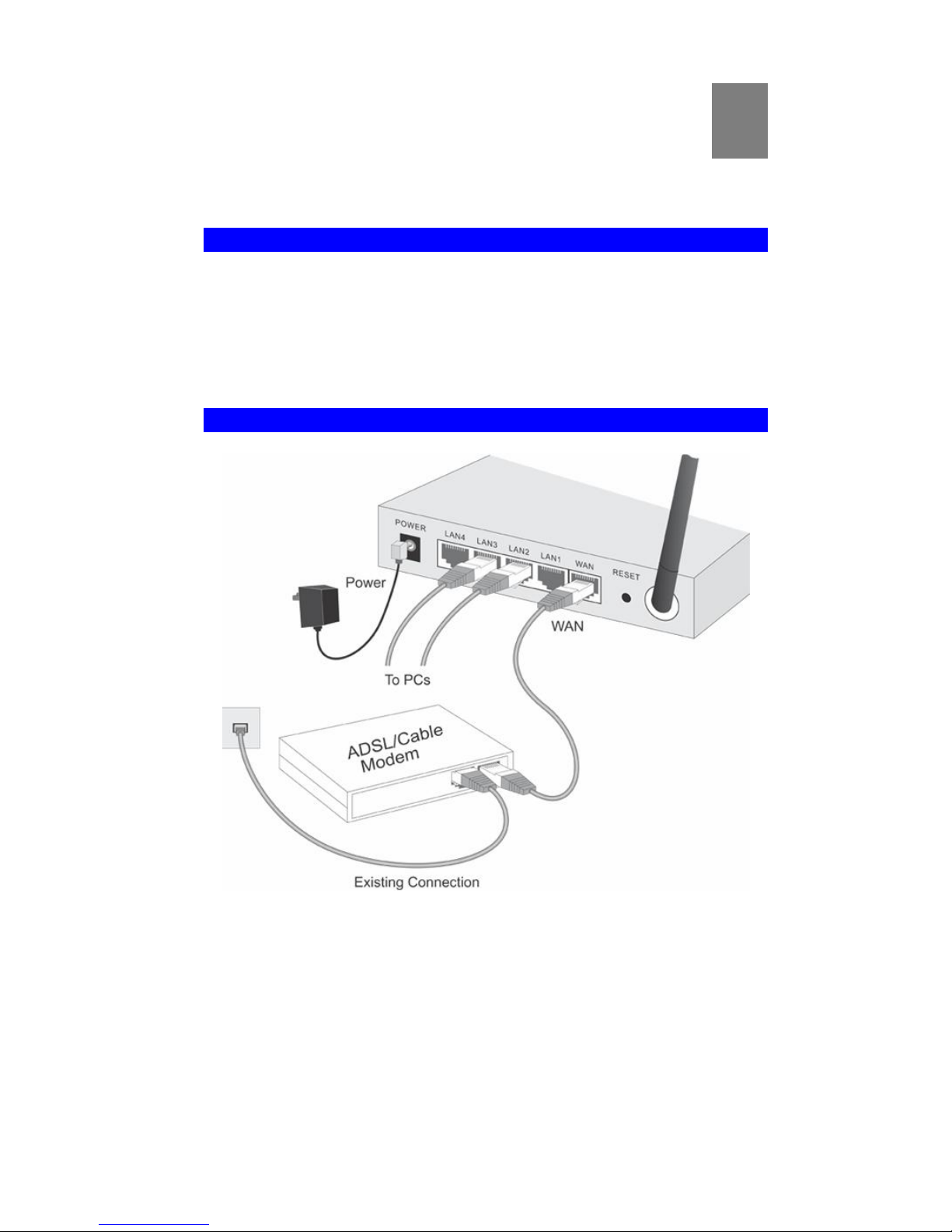
Procedure
Figure 4: Installation Diagram
1. Choose an Installation Site
Select a suitable place on the network to install the Wireless Router.
Ensure the Wireless Router and the DSL/Cable modem are powered OFF.
2
Page 11

Installation
7
For best Wireless reception and performance, the Wireless
Router should be positioned in a central location with minimum obstructions between the Wireless Router and the
PCs.
Also, if using multiple Access Points, adjacent Access
Points should use different Channels.
2. Connect LAN Cables
Use standard LAN cables to connect PCs to the Switching Hub ports on the Wireless
Router. Both 10BaseT and 100BaseT connections can be used simultaneously.
If required, connect any port to a normal port on another Hub, using a standard LAN cable.
Any LAN port on the Wireless Router will automatically function as an "Uplink" port
when required.
3. Connect WAN Cable
Connect the DSL or Cable modem to the WAN port on the Wireless Router. Use the cable
supplied with your DSL/Cable modem. If no cable was supplied, use a standard cable.
4. Power Up
" Power on the Cable or DSL modem.
" Connect the supplied power adapter to the Wireless Router and power up.
Use only the power adapter provided. Using a different one may cause hardware damage
5. Check the LEDs
" The Power LED should be ON.
" The Status LED should flash, then turn Off. If it stays on, there is a hardware error.
" For each LAN (PC) connection, the LAN Link/Act LED should be ON (provided the PC is
also ON.)
" The WAN LED should be ON.
" The Wireless LED should be ON
For more information, refer to Front-mounted LEDs in Chapter 1.
Page 12

8
Chapter 3
Setup
This Chapter provides Setup details of the Wireless Router.
Overview
This chapter describes the setup procedure for:
" Internet Access
" LAN configuration
" Wireless setup
" Assigning a Password to protect the configuration data.
PCs on your local LAN may also require configuration. For details, see Chapter 4 - PC Configuration.
Other configuration may also be required, depending on which features and functions of the
Wireless Router you wish to use. Use the table below to locate detailed instructions for the
required functions.
To Do this: Refer to:
Configure PCs on your LAN. Chapter 4:
PC Configuration
Check Wireless Router operation and Status. Chapter 5:
Operation and Status
Use any of the following Advanced features:
" Access Control
" Dynamic DNS
" Advanced Internet (Special Applications, DMZ
" URL Filter
" Schedule
" User Groups (for Access Control & URL Filter)
" Virtual Servers (Port Forwarding)
" WAN Port Setup
Chapter 6:
Advanced Features
Use any of the following Administration Configuration
settings or features:
" Config File download/upload
" Logs
" Network Diagnostics (Ping, DNS Lookup)
" Options (Backup DNS, UPnP, Firewall)
" PC Database
" Remote Administration
" Routing (RIP and static Routing)
" Security settings
" Firmware Upgrade
Chapter 7
Advanced Administration
3
Page 13

Setup
9
Configuration Program
The Wireless Router contains an HTTP server. This enables you to connect to it, and configure
it, using your Web Browser. Your Browser must support JavaScript.
The configuration program has been tested on the following browsers:
" Netscape V4.08 or later
" Internet Explorer V4 or later
Preparation
Before attempting to configure the Wireless Router, please ensure that:
" Your PC can establish a physical connection to the Wireless Router. The PC and the
Wireless Router must be directly connected (using the Hub ports on the Wireless Router)
or on the same LAN segment.
" The Wireless Router must be installed and powered ON.
" If the Wireless Router's default IP Address (192.168.0.1) is already used by another device,
the other device must be turned OFF until the Wireless Router is allocated a new IP Address during configuration.
Using UPnP
If your Windows system supports UPnP, an icon for the Wireless Router will appear in the
system tray, notifying you that a new network device has been found, and offering to create a
new desktop shortcut to the newly-discovered device.
" Unless you intend to change the IP Address of the Wireless Router, you can accept the
desktop shortcut.
" Whether you accept the desktop shortcut or not, you can always find UPnP devices in My
Network Places (previously called Network Neighborhood).
" Double - click the icon for the Wireless Router (either on the Desktop, or in My Network
Places) to start the configuration. Refer to the following section Setup Wizard for details of
the initial configuration process.
Using your Web Browser
To establish a connection from your PC to the Wireless Router:
1. After installing the Wireless Router in your LAN, start your PC. If your PC is already
running, restart it.
2. Start your WEB browser.
3. In the Address box, enter "HTTP://" and the IP Address of the Wireless Router, as in this
example, which uses the Wireless Router's default IP Address:
HTTP://192.168.0.1
Because the default password is blank, your will not be prompted for a password. However,
you should use the Password screen to assign a password.
Page 14

Wireless Router User Guide
10
If you can't connect
If the Wireless Router does not respond, check the following:
" The Wireless Router is properly installed, LAN connection is OK, and it is
powered ON. You can test the connection by using the "Ping" command:
" Open the MS-DOS window or command prompt window.
" Enter the command:
ping 192.168.0.1
If no response is received, either the connection is not working, or your
PC's IP address is not compatible with the Wireless Router's IP Address.
(See next item.)
" If your PC is using a fixed IP Address, its IP Address must be within the range
192.168.0.2 to 192.168.0.254 to be compatible with the Wireless Router's default IP Address of 192.168.0.1. Also, the Network Mask must be set to
255.255.255.0. See Chapter 4 - PC Configuration for details on checking your
PC's TCP/IP settings.
" Ensure that your PC and the Wireless Router are on the same network segment.
(If you don't have a router, this must be the case.)
" Ensure you are using the wired LAN interface. The Wireless interface can only
be used if its configuration matches your PC's wireless settings.
Page 15
Setup
11
Setup Wizard
The first time you connect to the Wireless Router, the Setup Wizard will run automatically.
(The Setup Wizard will also run if the Wireless Router's default settings are restored.)
1. Step through the Wizard until finished.
" You need to know the type of Internet connection service used by your ISP. Check the
data supplied by your ISP.
" The common connection types are explained in the tables below.
2. On the final screen of the Wizard, run the test and check that an Internet connection can be
established.
3. If the connection test fails:
" Check your data, the Cable/DSL modem, and all connections.
" Check that you have entered all data correctly.
" If using a Cable modem, your ISP may have recorded the MAC (physical) address of
your PC. Run the Wizard, and on the Cable Modem screen, use the "Clone MAC address" button to copy the MAC address from your PC to the Wireless Router.
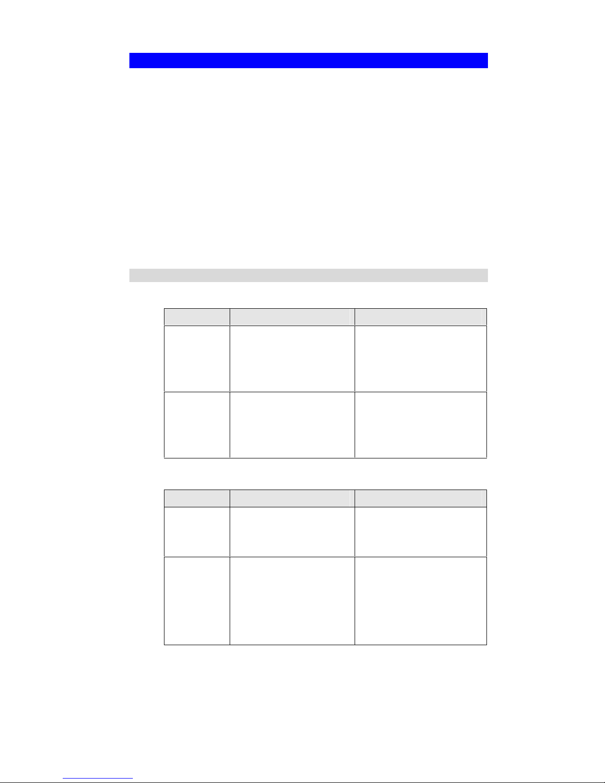
Common Connection Types
Cable Modems (TV-style cable)
Type Details ISP Data required
Dynamic
IP Address
Your IP Address is allocated
automatically, when you
connect to you ISP.
Usually, none.
However, some ISP's may
require you to use a particular
Hostname, Domain name, or
MAC (physical) address.
Static (Fixed)
IP Address
Your ISP allocates a permanent IP Address to you.
IP Address allocated to you.
Some ISP's may also require
you to use a particular Hostname, Domain name, or MAC
(physical) address.
DSL/ADSL Modems (phone-type cable)
Type Details ISP Data required
PPPoE You connect to the ISP only
when required. The IP address
is usually allocated automatically.
User name, password, Connection behavior, and Autodisconnect Timeout period.
PPTP PPTP is mainly used in
Europe.
You connect to the ISP only
when required. The IP address
is usually allocated automatically, but may be Static
(Fixed).
Server Address – Name or IP
Address allocated to you, if
Static (Fixed).
User name, password, Connection behavior, and Autodisconnect Timeout period.
Page 16

Wireless Router User Guide
12
L2TP L2TP is rarely used.
You connect to the ISP only
when required. The IP address
is usually allocated automatically, but may be Static
(Fixed).
Server Address – Name or IP
Address allocated to you, if
Static (Fixed).
User name, password, Connection behavior, and Autodisconnect Timeout period.
Dynamic
IP Address
Your IP Address is allocated
automatically, when you
connect to you ISP.
None.
Static (Fixed)
IP Address
Your ISP allocates a permanent IP Address to you.
IP Address allocated to you.
Telstra Bigpond Cable (Australia)
For this connection method, the following data is required:
" Big Pond Server IP address
" User Name
" Password
" Connection behavior
" Auto-disconnect Timeout period
SingTel RAS
For this connection method, the following data is required:
" User Name
" Password
" RAS Plan
" Connection behavior
" Auto-disconnect Timeout period
Other (e.g. Fixed Wireless)
Type Details ISP Data required
Dynamic
IP Address
Your IP Address is allocated
automatically, when you
connect to you ISP.
None.
Static (Fixed)
IP Address
Your ISP allocates a permanent IP Address to you.
IP Address allocated to you.
Page 17
Setup
13
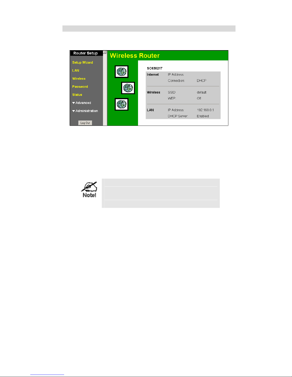
Home Screen
After finishing the Setup Wizard, you will see the Home screen. When you connect in future,
you will see this screen when you connect. An example screen is shown below.
Figure 5: Home Screen
Navigation & Data Input
" Use the menu bar on the left of the screen, and the "Back" button on your Browser, for
navigation.
" Changing to another screen without clicking "Save" does NOT save any changes you may
have made. You must "Save" before changing screens or your data will be ignored.
On each screen, clicking the "Help" button will
display help for that screen.
From any help screen, you can access the list of all
help files (help index).
Page 18
Wireless Router User Guide
14
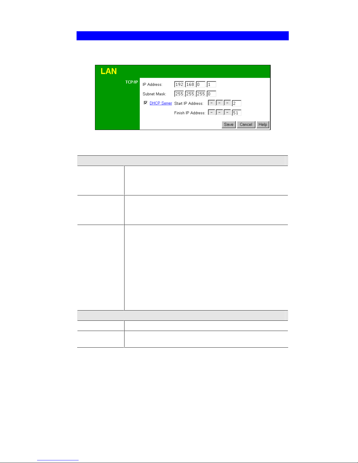
LAN Screen
Use the LAN link on the main menu to reach the LAN screen. An example screen is shown
below.
Figure 6: LAN Screen
Data - LAN Screen
TCP/IP
IP Address
IP address for the Wireless Router, as seen from the local LAN. Use
the default value unless the address is already in use or your LAN is
using a different IP address range. In the latter case, enter an unused IP
Address from within the range used by your LAN.
Subnet Mask
The default value 255.255.255.0 is standard for small (class "C")
networks. For other networks, use the Subnet Mask for the LAN
segment to which the Wireless Router is attached (the same value as the
PCs on that LAN segment).
DHCP Server
" If Enabled, the Wireless Router will allocate IP Addresses to PCs
(DHCP clients) on your LAN when they start up. The default (and
recommended) value is Enabled.
" If you are already using a DHCP Server, this setting must be
Disabled, and the existing DHCP server must be re-configured to
treat the Wireless Router as the default Gateway. See the following
section for further details.
" The Start IP Address and Finish IP Address fields set the values
used by the DHCP server when allocating IP Addresses to DHCP
clients. This range also determines the number of DHCP clients
supported.
See the following section for further details on using DHCP.
Buttons
Save
Save the data on screen.
Cancel
The "Cancel" button will discard any data you have entered and reload
the file from the Wireless Router.
Page 19

Setup
15
DHCP
What DHCP Does
A DHCP (Dynamic Host Configuration Protocol) Server allocates a valid IP address to a
DHCP Client (PC or device) upon request.
" The client request is made when the client device starts up (boots).
" The DHCP Server provides the Gateway and DNS addresses to the client, as well as
allocating an IP Address.
" The Wireless Router can act as a DHCP server.
" Windows 95/98/ME, Windows 2000 and Windows XP act as a DHCP client. This is the
default Windows setting for the TCP/IP network protocol. However, Windows uses the
term Obtain an IP Address automatically instead of "DHCP Client".
" You must NOT have two (2) or more DHCP Servers on the same LAN segment. (If your
LAN does not have other Routers, this means there must only be one (1) DHCP Server on
your LAN.)
Using the Wireless Router's DHCP Server
This is the default setting. The DHCP Server settings are on the LAN screen. On this screen,
you can:
" Enable or Disable the Wireless Router's DHCP Server function.
" Set the range of IP Addresses allocated to PCs by the DHCP Server function.
You can assign Fixed IP Addresses to some devices
while using DHCP, provided that the Fixed IP Addresses
are NOT within the range used by the DHCP Server.
Using another DHCP Server
You can only use one (1) DHCP Server per LAN segment. If you wish to use another DHCP
Server, rather than the Wireless Router's, the following procedure is required.
1. Disable the DHCP Server feature in the Wireless Router. This setting is on the LAN screen.
2. Configure the DHCP Server to provide the Wireless Router's IP Address as the Default
Gateway.
To Configure your PCs to use DHCP
This is the default setting for TCP/IP under Windows 95/98/ME.
See Chapter 4 - Client Configuration for the procedure to check these settings.
Page 20
Wireless Router User Guide
16
Wireless Screen
The Wireless Router's settings must match the other Wireless stations.
Note that the Wireless Router will automatically accept both 802.11b and 802.11g connections,
and no configuration is required for this feature.
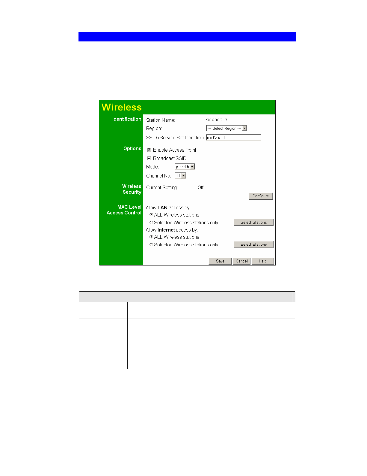
To change the Wireless Router's default settings for the Wireless Access Point feature, use the
Wireless link on the main menu to reach the Wireless screen. An example screen is shown
below.
Figure 7: Wireless Screen
Data - Wireless Screen
Identification
Station name
On your PC, some Wireless status screens may display this name as the
Access Point in use.
Region
Select your region from the drop-down list. This field displays the
region of operation for which the wireless interface is intended. It may
not be legal to operate the router in a region other than the region
shown here. If your country or region is not listed, please check with
your local government agency for more information on which channels
you are allowed to use, and select a region which allows those channels. (The channel list changes according to the selected region.)
Page 21

Setup
17
SSID
" If using an ESS (Extended Service Set, with multiple access
points) this ID is called an ESSID (Extended Service Set Identifier).
" To communicate, all Wireless stations should use the same
SSID/ESSID.
Options
Enable Access
Point
" If Enabled, wireless stations will be able to locate and use this
Access Point.
" If Disabled, the wireless interface is disabled, and will neither
transmit nor receive wireless traffic.
" The Wireless (WLAN) LED on the front panel will remain OFF if
the Wireless interface is disabled.
Broadcast SSID
If Enabled, the SSID will broadcast its name to all Wireless Stations.
Stations which have no SSID (or a "null" value) can then adopt the
correct SSID for connections to this Access Point.
Mode
Select the desired option:
" g & b - This is the default, and should normally be used.
" g only - If selected, this ensures that "g" mode stations will connect
at high speed, but "b" mode stations will be unable to connect at
all.
" b only - If selected, "g" mode is unavailable. "g" mode stations will
only be able to connect if they are fully backward-compatible with
"b" mode.
Channel
No
This field determines which operating frequency will be used. It should
not be necessary to change the wireless channel unless you notice
interference problems with another nearby access point.
Wireless Security
Current Setting
The current security setting is displayed.
Configure
Button
Click this button to access the Wireless security sub-screen, and modify
the security settings as required.
MAC Level Access Control
Allow LAN
access
This feature can be used to prevent unknown Wireless stations from
accessing your LAN. The available options are:
" All Wireless Stations - All wireless stations can use the access
point to access your LAN.
" Selected Wireless stations only - Only selected wireless stations
access your LAN. To select the required wireless stations, click the
"Select Stations" button.
Allow Internet
access
This feature can prevent unknown Wireless stations from using the
Wireless Router to access the Internet. The available options are:
" All Wireless Stations - All wireless stations can use the access
point to access the Internet.
" Selected Wireless stations only - Only selected wireless stations
can use the access point to access the Internet. To select the required wireless stations, click the "Select Stations" button.
Page 22
Wireless Router User Guide
18
Wireless Security
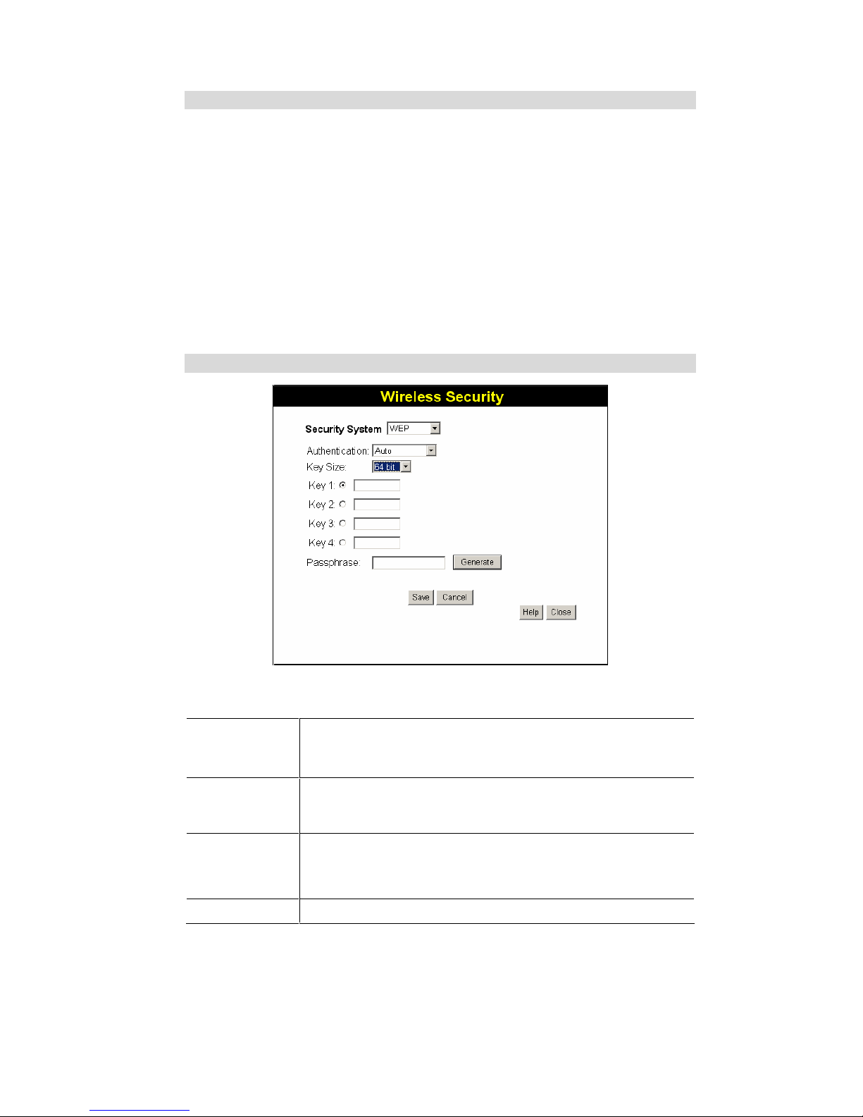
This screen is accessed by clicking the "Configure" button on the Wireless screen. There are 3
options for Wireless security:
" Disabled - no data encryption is used.
" WEP - data is encrypted using the WEP standard.
" WPA - data is encrypted using the WPA-PSK standard. This is a later standard than WEP,
and provides much better security than WEP. If all your Wireless stations support WPAPSK, you should use WPA-PSK rather than WEP.
" WPA2 - data is encrypted always using the AES (Advanced Encryption Standard). This is
a later version of WPA which offers improved security.
" WPA+WPA2 - data is encrypted using either WPA-PSK or WPA2-PSK standard. This
option is sometimes called "Mixed Mode"
"
WEP Wireless Security
Figure 8: WEP Screen
Data - WEP Screen
Security
System
WEP
The 802.11b standard. Data is encrypted before transmission, but the
encryption system is not very strong.
Authentication
Normally this can be left at the default value of "Auto". If that fails,
select the appropriate value - "Open System" or "Shared Key." Check
your wireless station's documentation to see what method to use.
Data
Key Size
Select the WEP Encryption level:
" 64-bit (sometimes called 40-bit) encryption
" 128-bit (sometimes called 104 bit) encryption
Keys
All wireless stations must use the same key values as the Wireless
Page 23
Setup
19
Router.
" Use the radio buttons to select the default key.
" Enter the key value you wish to use. Other stations must have the
same key values.
" Keys must be entered in Hex.
Hex characters are the digits (0 ~ 9) and the letters A ~ F.
Passphrase
This feature allows you to generate a key or keys from a text (ASCII)
phrase, rather than enter keys in Hex.
To use this feature:
" Enter a word or group of printable characters in the Passphrase
field
" Click the "Generate Key" button.
" If encryption strength is set to 64 bit, then each of the four key
fields will be populated with key values. If encryption strength is
set to 128 bit, then only the selected WEP key field will be given a
key value.
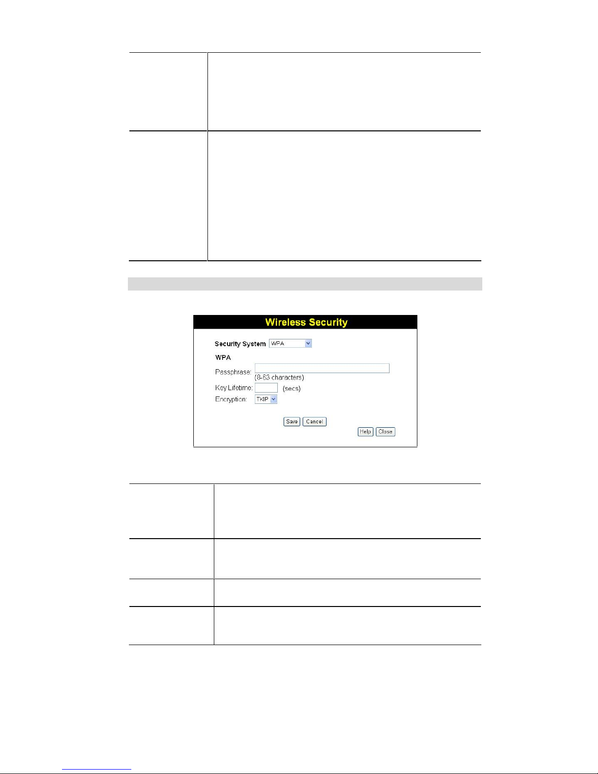
WPA Wireless Security
If "WPA" is selected, the screen will look like the following example.
Figure 9: WPA Screen
Data – WPA Screen
Security
System
WPA
Like WEP, data is encrypted before transmission. WPA is more
secure than WEP, and should be used if possible. WPA is the version
of WPA, which does NOT require a Radius Server on your LAN.
Passphrase (PSK)
Enter the Keyword key value. Data is encrypted using a key derived
from the network key. Other Wireless Stations must use the same
network key. The PSK must be from 8 to 63 characters in length.
Key Lifetime
This determines how often the encryption key is changed. You can
change the default value if desired.
Encryption
The WPA standard allows different encryption methods to be used.
Select the desired option. Wireless Stations must use the same encryption method.
Page 24
Wireless Router User Guide
20
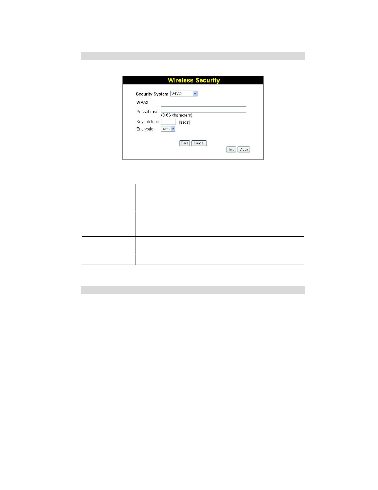
WPA2 Wireless Security
If "WPA2" is selected, the screen will look like the following example.
Figure 10: WPA2 Screen
Data – WPA2 Screen
Security
System
WPA2
This is a later version of WPA which offers improved security. AES
encryption is always used.
Passphrase (PSK)
Enter the Keyword key value. Data is encrypted using a key derived
from the network key. Other Wireless Stations must use the same
network key. The PSK must be from 8 to 63 characters in length.
Key Lifetime
This determines how often the encryption key is changed. You can
change the default value if desired.
Encryption
AES must be used.
WPA+WPA2 Wireless Security
If "WPA+WPA2" is selected, the screen will look like the following example.
Page 25

Setup
21
Figure 11: WPA+WPA2 Screen
Data – WPA+WPA2 Screen
Security
System
WPA+WPA2
If selected, wireless clients may use either WPA or WPA2. This
option is sometimes called "Mixed Mode".
Passphrase (PSK)
Enter the Keyword key value. Data is encrypted using a key derived
from the network key. Other Wireless Stations must use the same
network key. The PSK must be from 8 to 63 characters in length.
Key Lifetime
This determines how often the encryption key is changed. You can
change the default value if desired.
Encryption
Only one option is available - TKIP+AES. Clients may use either
WPA (with TKIP) or WPA (with AES).
Page 26

Wireless Router User Guide
22
Password Screen
The password screen allows you to assign a password to the Wireless Router.
Figure 12: Password Screen
Once you have assigned a password to the Wireless Router (on the Password screen above) you
will be prompted for the password when you connect, as shown below. (If no password has
been set, this dialog will not appear.)
Figure 13: Password Dialog
" Leave the "User Name" blank.
" Enter the password for the Wireless Router, as set on the Password screen above.
Page 27

23
Chapter 4
PC Configuration
This Chapter details the PC Configuration required on the local ("Internal")
LAN.
Overview
For each PC, the following may need to be configured:
" TCP/IP network settings
" Internet Access configuration
" Wireless configuration
Windows Clients
This section describes how to configure Windows clients for Internet access via the Wireless
Router.
The first step is to check the PC's TCP/IP settings.
The Wireless Router uses the TCP/IP network protocol for all functions, so it is essential that
the TCP/IP protocol be installed and configured on each PC.
TCP/IP Settings - Overview
If using the default Wireless Router settings and the default Windows
TCP/IP settings, no changes need to be made.
" By default, the Wireless Router will act as a DHCP Server, automatically providing a
suitable IP Address (and related information) to each PC when the PC boots.
" For all non-Server versions of Windows, the default TCP/IP setting is to act as a DHCP
client.
If using a Fixed (specified) IP address, the following changes are required:
" The Gateway must be set to the IP address of the Wireless Router
" The DNS should be set to the address provided by your ISP.
If your LAN has a Router, the LAN Administrator must reconfigure the Router itself. Refer to Chapter 8 - Advanced
Setup for details.
4
Page 28
Wireless Router User Guide
24
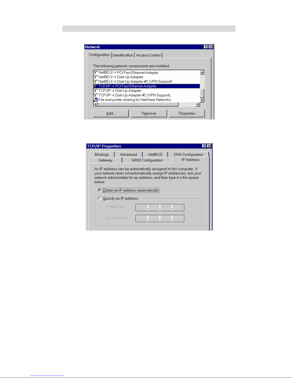
Checking TCP/IP Settings - Windows 9x/ME:
1. Select Control Panel - Network. You should see a screen like the following:
Figure 14: Network Configuration
2. Select the TCP/IP protocol for your network card.
3. Click on the Properties button. You should then see a screen like the following.
Figure 15: IP Address (Win 95)
Ensure your TCP/IP settings are correct, as follows:
Using DHCP
To use DHCP, select the radio button Obtain an IP Address automatically. This is the default
Windows setting. Using this is recommended. By default, the Wireless Router will act as a
DHCP Server.
Restart your PC to ensure it obtains an IP Address from the Wireless Router.
Using "Specify an IP Address"
If your PC is already configured, check with your network administrator before making the
following changes:
Page 29

PC Configuration
25
" On the Gateway tab, enter the Wireless Router's IP address in the New Gateway field and
click Add, as shown below. Your LAN administrator can advise you of the IP Address they
assigned to the Wireless Router.
Figure 16: Gateway Tab (Win 95/98)
" On the DNS Configuration tab, ensure Enable DNS is selected. If the DNS Server Search
Order list is empty, enter the DNS address provided by your ISP in the fields beside the
Add button, then click Add.
Figure 17: DNS Tab (Win 95/98)
Page 30
Wireless Router User Guide
26
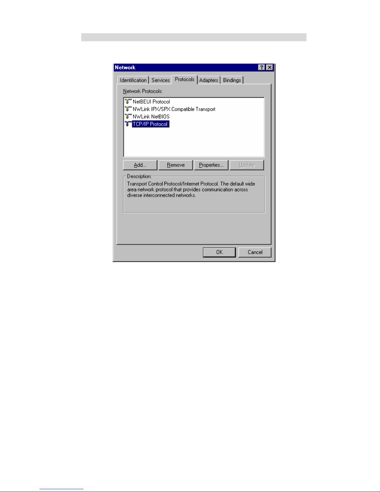
Checking TCP/IP Settings - Windows NT4.0
1. Select Control Panel - Network, and, on the Protocols tab, select the TCP/IP protocol, as
shown below.
Figure 18: Windows NT4.0 - TCP/IP
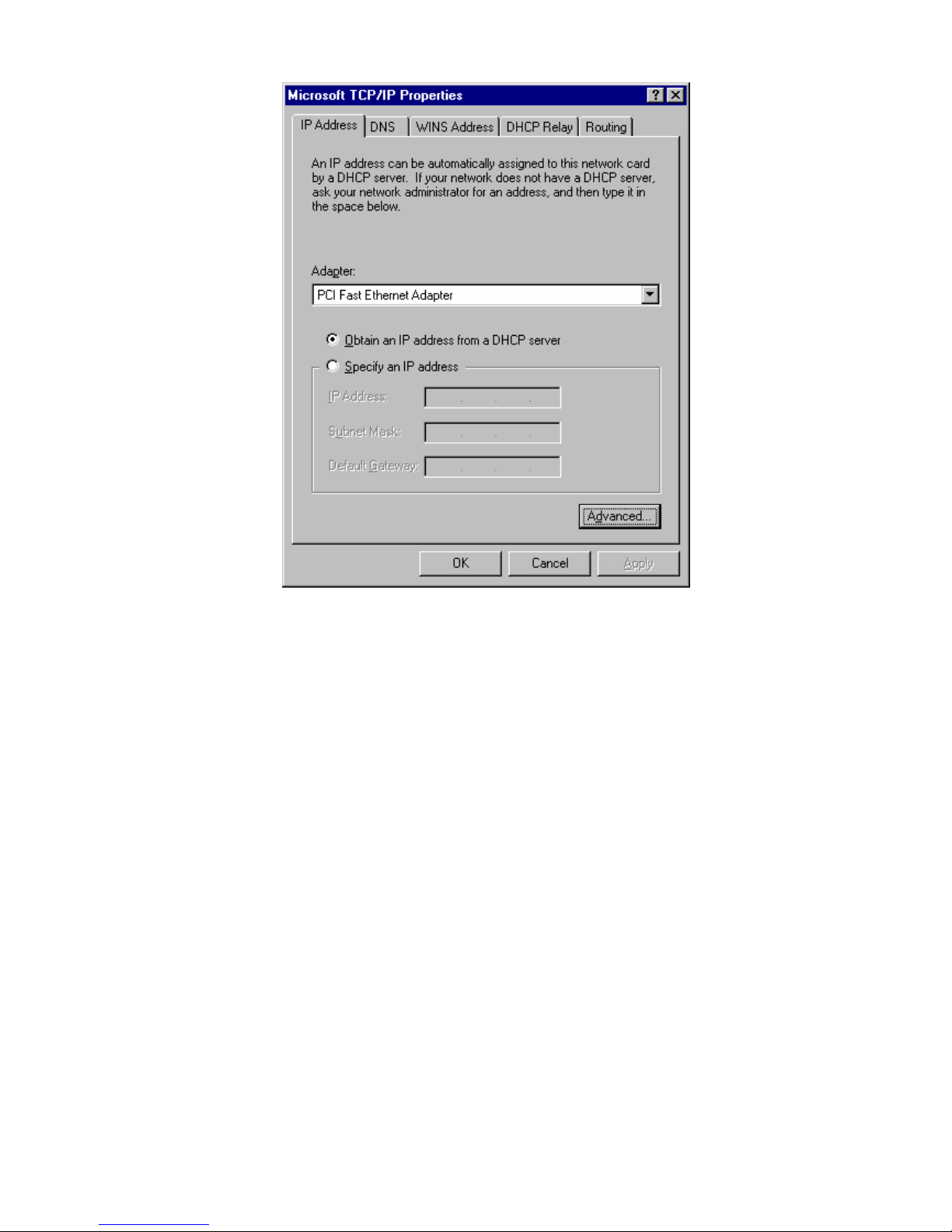
2. Click the Properties button to see a screen like the one below.
Page 31
PC Configuration
27
Figure 19: Windows NT4.0 - IP Address
3. Select the network card for your LAN.
4. Select the appropriate radio button - Obtain an IP address from a DHCP Server or Specify
an IP Address, as explained below.
Obtain an IP address from a DHCP Server
This is the default Windows setting. Using this is recommended. By default, the Wireless
Router will act as a DHCP Server.
Restart your PC to ensure it obtains an IP Address from the Wireless Router.
Specify an IP Address
If your PC is already configured, check with your network administrator before making the
following changes.
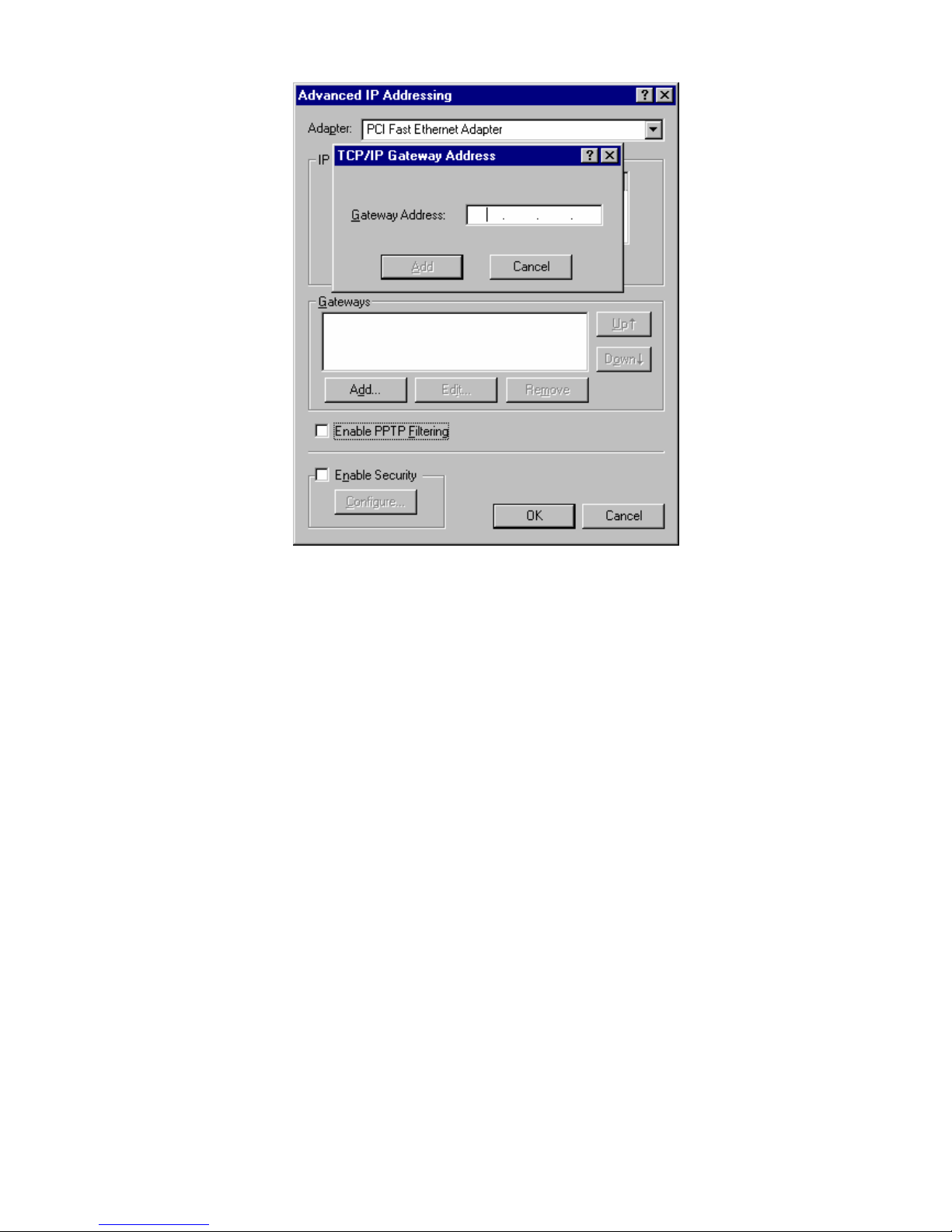
1. The Default Gateway must be set to the IP address of the Wireless Router. To set this:
" Click the Advanced button on the screen above.
" On the following screen, click the Add button in the Gateways panel, and enter the
Wireless Router's IP address, as shown in Figure 20 below.
" If necessary, use the Up button to make the Wireless Router the first entry in the
Gateways list.
Page 32
Wireless Router User Guide
28
Figure 20 - Windows NT4.0 - Add Gateway
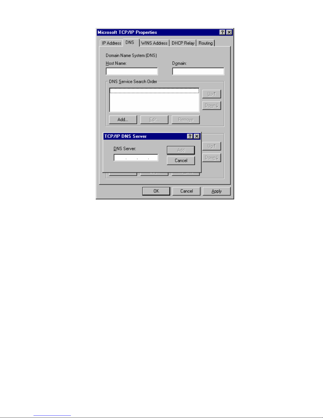
2. The DNS should be set to the address provided by your ISP, as follows:
" Click the DNS tab.
" On the DNS screen, shown below, click the Add button (under DNS Service Search
Order), and enter the DNS provided by your ISP.
Page 33
PC Configuration
29
Figure 21: Windows NT4.0 - DNS
Page 34
Wireless Router User Guide
30
Checking TCP/IP Settings - Windows 2000:
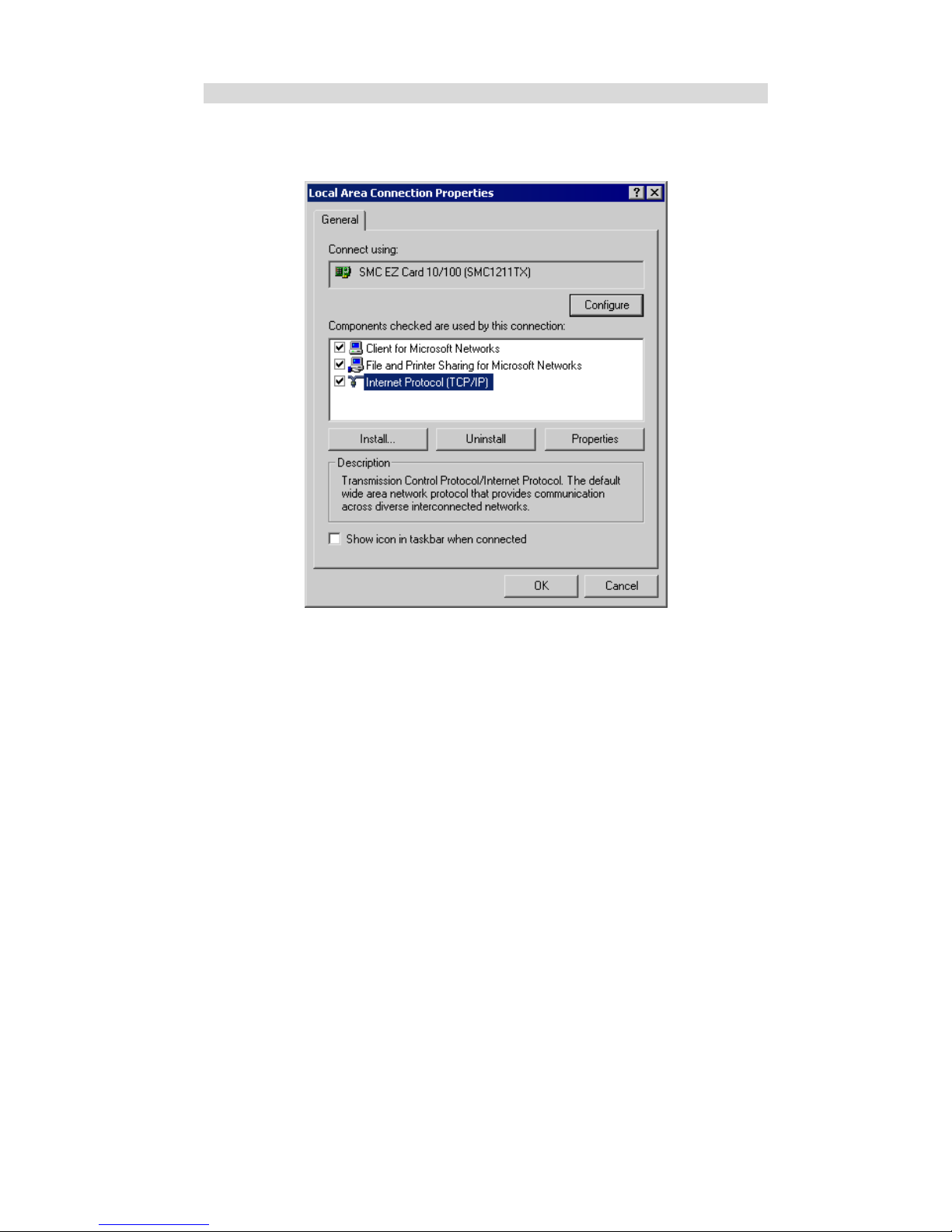
1. Select Control Panel - Network and Dial-up Connection.
2. Right - click the Local Area Connection icon and select Properties. You should see a
screen like the following:
Figure 22: Network Configuration (Win 2000)
3. Select the TCP/IP protocol for your network card.
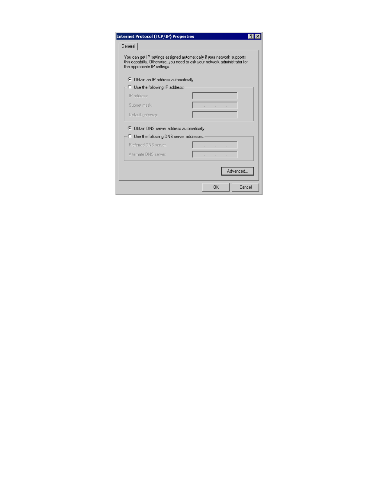
4. Click on the Properties button. You should then see a screen like the following.
Page 35
PC Configuration
31
Figure 23: TCP/IP Properties (Win 2000)
5. Ensure your TCP/IP settings are correct, as described below.
Using DHCP
To use DHCP, select the radio button Obtain an IP Address automatically. This is the default
Windows setting. Using this is recommended. By default, the Wireless Router will act as a
DHCP Server.
Restart your PC to ensure it obtains an IP Address from the Wireless Router.
Using a fixed IP Address ("Use the following IP Address")
If your PC is already configured, check with your network administrator before making the
following changes.
" Enter the Wireless Router's IP address in the Default gateway field and click OK. (Your
LAN administrator can advise you of the IP Address they assigned to the Wireless Router.)
" If the DNS Server fields are empty, select Use the following DNS server addresses, and
enter the DNS address or addresses provided by your ISP, then click OK.
Page 36
Wireless Router User Guide
32
Checking TCP/IP Settings - Windows XP
1. Select Control Panel - Network Connection.
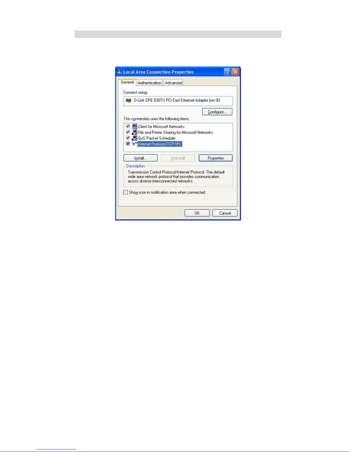
2. Right click the Local Area Connection and choose Properties. You should see a screen
like the following:
Figure 24: Network Configuration (Windows XP)
3. Select the TCP/IP protocol for your network card.
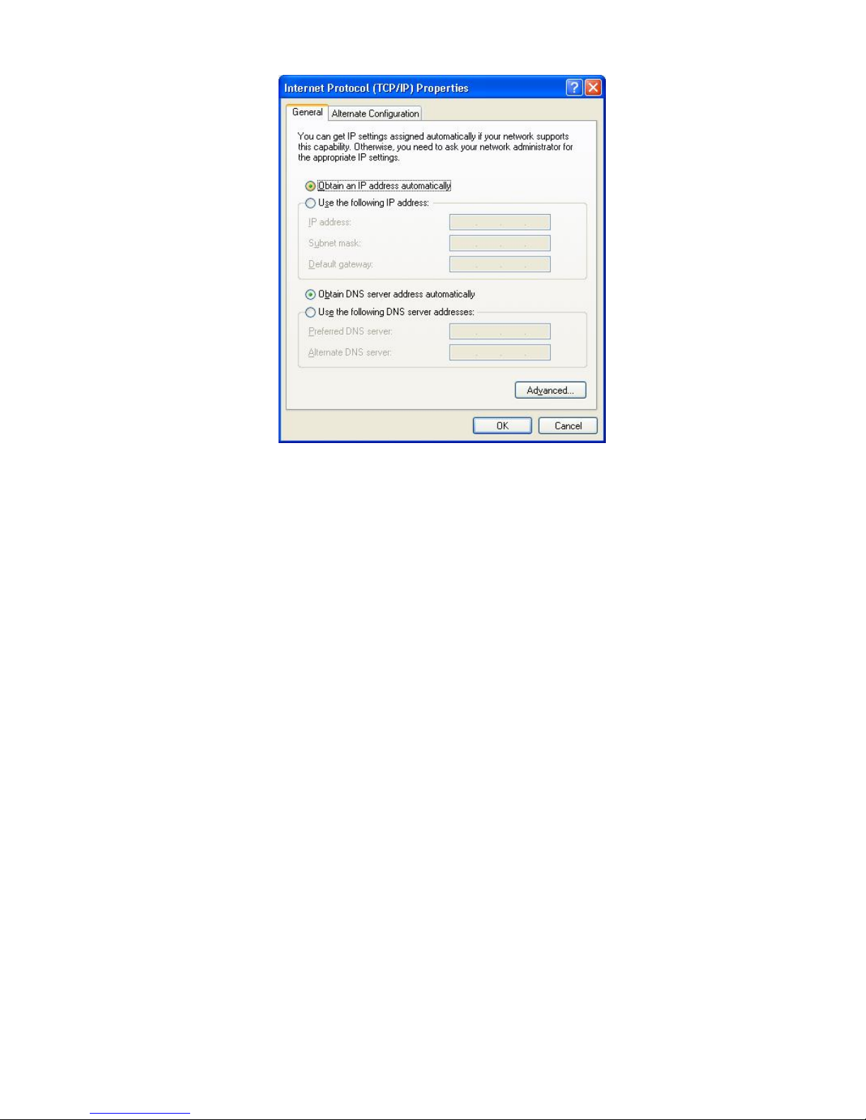
4. Click on the Properties button. You should then see a screen like the following.
Page 37
PC Configuration
33
Figure 25: TCP/IP Properties (Windows XP)
5. Ensure your TCP/IP settings are correct.
Using DHCP
To use DHCP, select the radio button Obtain an IP Address automatically. This is the default
Windows setting. Using this is recommended. By default, the Wireless Router will act as a
DHCP Server.
Restart your PC to ensure it obtains an IP Address from the Wireless Router.
Using a fixed IP Address ("Use the following IP Address")
If your PC is already configured, check with your network administrator before making the
following changes.
" In the Default gateway field, enter the Wireless Router's IP address and click OK. Your
LAN administrator can advise you of the IP Address they assigned to the Wireless Router.
" If the DNS Server fields are empty, select Use the following DNS server addresses, and
enter the DNS address or addresses provided by your ISP, then click OK.
Page 38

Wireless Router User Guide
34
Internet Access
To configure your PCs to use the Wireless Router for Internet access:
" Ensure that the DSL modem, Cable modem, or other permanent connection is functional.
" Use the following procedure to configure your Browser to access the Internet via the LAN,
rather than by a Dial-up connection.
For Windows 9x/ME/2000
1. Select Start Menu - Settings - Control Panel - Internet Options.
2. Select the Connection tab, and click the Setup button.
3. Select "I want to set up my Internet connection manually, or I want to connect through a
local area network (LAN)" and click Next.
4. Select "I connect through a local area network (LAN)" and click Next.
5. Ensure all of the boxes on the following Local area network Internet Configuration screen
are unchecked.
6. Check the "No" option when prompted "Do you want to set up an Internet mail account
now?".
7. Click Finish to close the Internet Connection Wizard.
Setup is now completed.
For Windows XP
1. Select Start Menu - Control Panel - Network and Internet Connections.
2. Select Set up or change your Internet Connection.
3. Select the Connection tab, and click the Setup button.
4. Cancel the pop-up "Location Information" screen.
5. Click Next on the "New Connection Wizard" screen.
6. Select "Connect to the Internet" and click Next.
7. Select "Set up my connection manually" and click Next.
8. Check "Connect using a broadband connection that is always on" and click Next.
9. Click Finish to close the New Connection Wizard.
Setup is now completed.
Accessing AOL
To access AOL (America On Line) through the Wireless Router, the AOL for Windows software must be configured to use TCP/IP network access, rather than a dial-up connection. The
configuration process is as follows:
" Start the AOL for Windows communication software. Ensure that it is Version 2.5, 3.0 or
later. This procedure will not work with earlier versions.
" Click the Setup button.
" Select Create Location, and change the location name from "New Locality" to "Wireless
Router".
" Click Edit Location. Select TCP/IP for the Network field. (Leave the Phone Number blank.)
" Click Save, then OK.
Configuration is now complete.
" Before clicking "Sign On", always ensure that you are using the "Wireless Router" location.
Page 39

PC Configuration
35
Macintosh Clients
From your Macintosh, you can access the Internet via the Wireless Router. The procedure is as
follows.
1. Open the TCP/IP Control Panel.
2. Select Ethernet from the Connect via pop-up menu.
3. Select Using DHCP Server from the Configure pop-up menu. The DHCP Client ID field
can be left blank.
4. Close the TCP/IP panel, saving your settings.
Note:
If using manually assigned IP addresses instead of DHCP, the required changes are:
" Set the Router Address field to the Wireless Router's IP Address.
" Ensure your DNS settings are correct.
Linux Clients
To access the Internet via the Wireless Router, it is only necessary to set the Wireless Router as
the "Gateway".
Ensure you are logged in as "root" before attempting any changes.
Fixed IP Address
By default, most Unix installations use a fixed IP Address. If you wish to continue using a fixed
IP Address, make the following changes to your configuration.
" Set your "Default Gateway" to the IP Address of the Wireless Router.
" Ensure your DNS (Name server) settings are correct.
To act as a DHCP Client (recommended)
The procedure below may vary according to your version of Linux and X -windows shell.
1. Start your X Windows client.
2. Select Control Panel - Network
3. Select the "Interface" entry for your Network card. Normally, this will be called "eth0".
4. Click the Edit button, set the "protocol" to "DHCP", and save this data.
5. To apply your changes
" Use the "Deactivate" and "Activate" buttons, if available.
" OR, restart your system.
Other Unix Systems
To access the Internet via the Wireless Router:
" Ensure the "Gateway" field for your network card is set to the IP Address of the Wireless
Router.
" Ensure your DNS (Name Server) settings are correct.
Page 40

Wireless Router User Guide
36
Wireless Station Configuration
This section applies to all Wireless stations wishing to use the Wireless Router's Access Point,
regardless of the operating system which is used on the client.
To use the Wireless Access Point in the Wireless Router, each Wireless Station must have
compatible settings, as follows:
Mode The mode must be set to Infrastructure.
Most wireless stations will select the correct mode automatically.
SSID (ESSID)
This must match the value used on the Wireless Router. The default
value is default
Note! The SSID is case sensitive.
Wireless
Security
By default, Wireless security on the Wireless Router is disabled.
" If Wireless security remains disabled on the Wireless Router, all
stations must have wireless security disabled.
" If Wireless security is enabled on the Wireless Router (either WEP
or WPA), each station must use the same settings as the Wireless
Router.
Note:
By default, the Wireless Router will allow both 802.11b and 802.11g connections.
Page 41
37
Chapter 5
Operation and Status
This Chapter details the operation of the Wireless Router and the status
screens.
Operation
Once both the Wireless Router and the PCs are configured, operation is automatic.
However, there are some situations where additional Internet configuration may be required:
" If using Internet-based Communication Applications, it may be necessary to specify which
PC receives an incoming connection. Refer to Chapter 6 - Advanced Features for further
details.
" Applications which use non-standard connections or port numbers may be blocked by the
Wireless Router's built-in firewall. You can define such applications as Special Applica-
tions to allow them to function normally. Refer to Chapter 6 - Advanced Features for
further details.
" Some non-standard applications may require use of the DMZ feature. Refer to Chapter 6 -
Advanced Features for further details.
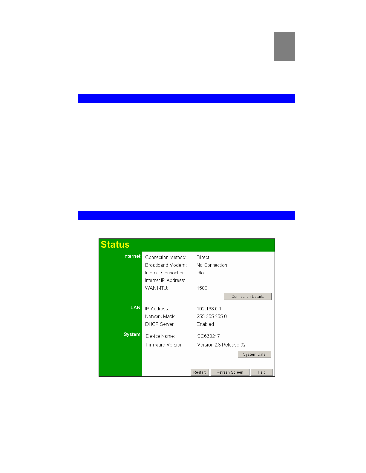
Status Screen
Use the Status link on the main menu to view this screen.
Figure 26: Status Screen
5
Page 42

Wireless Router User Guide
38
Data - Status Screen
Internet
Connection Method
This indicates the current connection method, as set in the Setup
Wizard or WAN Port screen.
Broadband Modem
This shows the status of the connection from the Wireless Router
to the Broadband Modem.
Internet Connection
Current connection status:
" Active - Currently connected.
" Idle - Not currently connected; previous connection termi-
nated normally.
" Unknown - This indicates an error. You should restart the
Dual-Band Wireless Router.
" Failed - Connection could not be established, or was termi-
nated abnormally.
The most common cause of failure is disconnection by your
ISP. In this case, you will be re-connected automatically.
Other problems could be caused by:
" The connection to the broadband modem.
" The broadband modem itself.
" The ADSL or cable connection could be unavailable.
" Your ISP's server may be currently unavailable.
" If using a "login" to connect to the ISP's server, the login
could have failed due to incorrect name or password.
If there is an error, you can click the "Connection Details" button
to find out more information.
Generally, the best method to deal with connection failure is:
1. Restart your Cable or DSL modem.
2. Check the LEDs on the Cable or DSL modem to see that it
has established a physical connection.
3. Restart the Wireless Router.
4. Run the Setup Wizard again, check that your settings are
correct, and run the connection test. Check the message given
by the test.
Internet IP Address
This IP Address is allocated by the ISP (Internet Service Provider). If there is no current connection, this will be blank or
0.0.0.0.
WAN MTU
Displays the current value of MTU (Maximum Transmission
Unit). The MTU determines the size of TCP/IP packets used for
the Internet connection. This rarely needs to be changed. If you do
need to change it, this setting is on the WAN Port screen.
Connection Details
Button
Click this button to open a sub-window and view a detailed
description of the current connection. Depending on the type of
connection, a "Connection Log" may also be available.
LAN
IP Address
The IP Address of the Wireless Router.
Page 43
Operation and Status
39
Network Mask
The Network Mask (Subnet Mask) for the IP Address above.
DHCP Server
This shows the status of the DHCP Server function - either "Enabled" or "Disabled".
For additional information about the PCs on your LAN, and the IP
addresses allocated to them, use the PC Database option on the
Administration menu.
System
Device Name
This displays the current name of the Wireless Router.
Firmware Version
The current version of the firmware installed in the Wireless
Router.
Buttons
Connection Details
View the details of the current Internet connection. The subscreen displayed will depend on the connection method used. See
the following sections for details of each sub-screen.
System Data
Display all system information in a sub-window.
Restart
Clicking this button will restart (reboot) the Wireless Router. All
existing connections though the Wireless Router will be terminated, but will usually re-connect automatically.
Refresh Screen
Update the data displayed on screen.
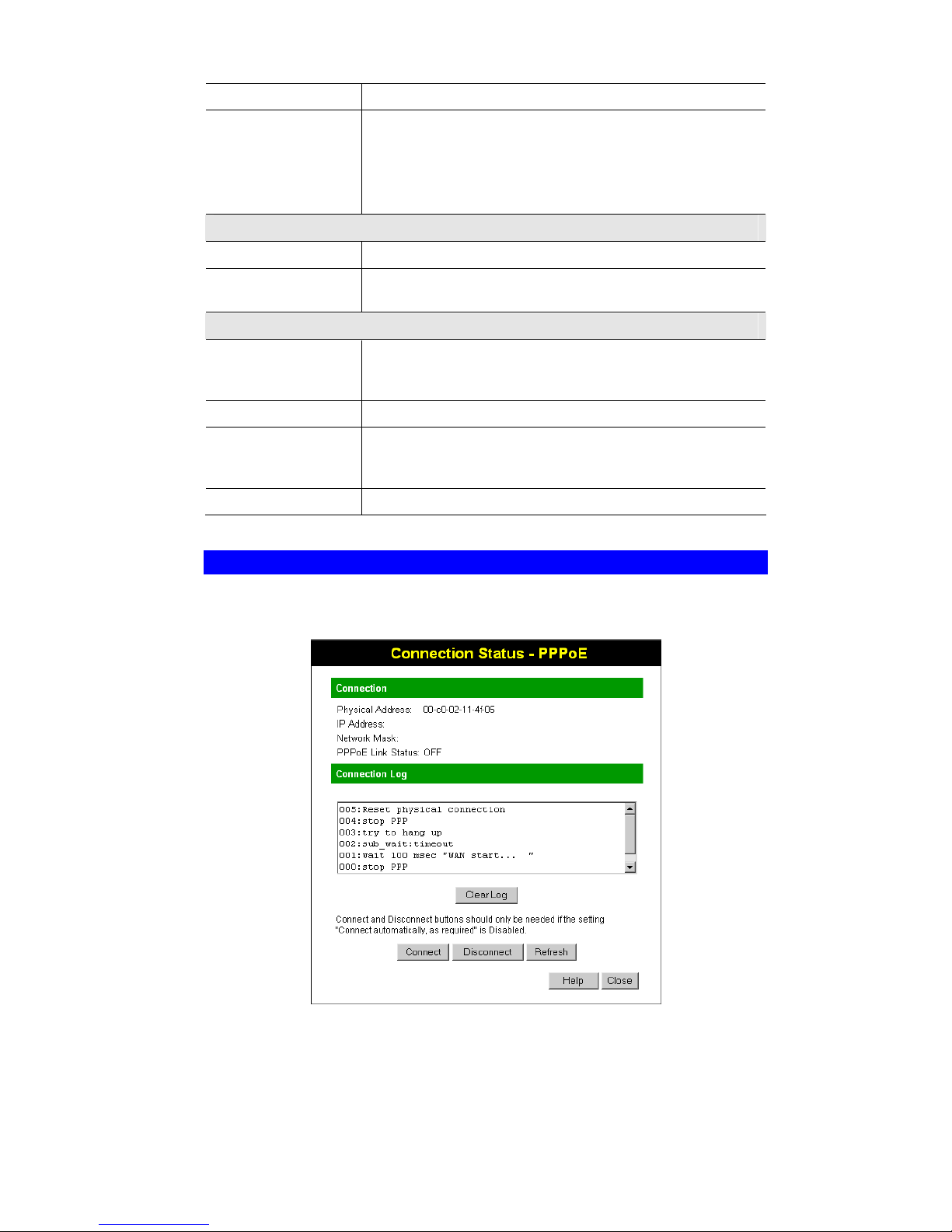
Connection Status - PPPoE
If using PPPoE (PPP over Ethernet), a screen like the following example will be displayed
when the "Connection Details" button is clicked.
Figure 27: PPPoE Status Screen
Page 44
Wireless Router User Guide
40
Data - PPPoE Screen
Connection
Physical Address
The hardware address of this device, as seen by remote devices on
the Internet. (This is different to the hardware address seen by
devices on the local LAN.)
IP Address
The IP Address of this device, as seen by Internet users. This
address is allocated by your ISP (Internet Service Provider).
Network Mask
The Network Mask associated with the IP Address above.
PPPoE Link Status
This indicates whether or not the connection is currently established.
" If the connection does not exist, the "Connect" button can be
used to establish a connection.
" If the connection currently exists, the "Disconnect" button
can be used to break the connection.
Connection Log
Connection Log
" The Connection Log shows status messages relating to the
existing connection.
" The most common messages are listed in the table below.
" The "Clear Log" button will restart the Log, while the Re-
fresh button will update the messages shown on screen.
Buttons
Connect
If not connected, establish a connection to your ISP.
Disconnect
If connected to your ISP, hang up the connection.
Clear Log
Delete all data currently in the Log. This will make it easier to
read new messages.
Refresh
Update the data on screen.
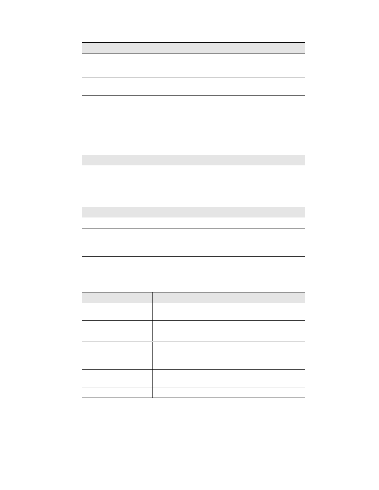
Connection Log Messages
Message Description
Connect on Demand Connection attempt has been triggered by the "Connect auto-
matically, as required" setting.
Manual connection Connection attempt started by the "Connect" button.
Reset physical connection Preparing line for connection attempt.
Connecting to remote
server
Attempting to connect to the ISP's server.
Remote Server located ISP's Server has responded to connection attempt.
Start PPP Attempting to login to ISP's Server and establish a PPP con-
nection.
PPP up successfully Able to login to ISP's Server and establish a PPP connection.
Page 45

Operation and Status
41
Idle time-out reached The connection has been idle for the time period specified in
the "Idle Time-out" field. The connection will now be termi-
nated.
Disconnecting The current connection is being terminated, due to either the
"Idle Time-out" above, or "Disconnect" button being clicked.
Error: Remote Server not
found
ISP's Server did not respond. This could be a Server problem,
or a problem with the link to the Server.
Error: PPP Connection
failed
Unable to establish a PPP connection with the ISP's Server.
This could be a login problem (name or password) or a Server
problem.
Error: Connection to
Server lost
The existing connection has been lost. This could be caused by
a power failure, a link failure, or Server failure.
Error: Invalid or unknown
packet type
The data received from the ISP's Server could not be proc-
essed. This could be caused by data corruption (from a bad
link), or the Server using a protocol which is not supported by
this device.
Page 46

Wireless Router User Guide
42
Connection Status - PPTP
If using PPTP (Peer-to-Peer Tunneling Protocol), a screen like the following example will be
displayed when the "Connection Details" button is clicked.
Figure 28: PPTP Status Screen
Data - PPTP Screen
Connection
Physical Address
The hardware address of this device, as seen by remote devices on the
Internet. (This is different to the hardware address seen by devices on
the local LAN.)
IP Address
The IP Address of this device, as seen by Internet users. This address
is allocated by your ISP (Internet Service Provider).
PPTP Status
This indicates whether or not the connection is currently established.
" If the connection does not exist, the "Connect" button can be
used to establish a connection.
" If the connection currently exists, the "Disconnect" button can be
used to break the connection.
Connection Log
Connection Log
" The Connection Log shows status messages relating to the
existing connection.
" The "Clear Log" button will restart the Log, while the Refresh
button will update the messages shown on screen.
Buttons
Connect
If not connected, establish a connection to your ISP.
Page 47
Operation and Status
43
Disconnect
If connected to your ISP, hang up the connection.
Clear Log
Delete all data currently in the Log. This will make it easier to read
new messages.
Refresh
Update the data on screen.
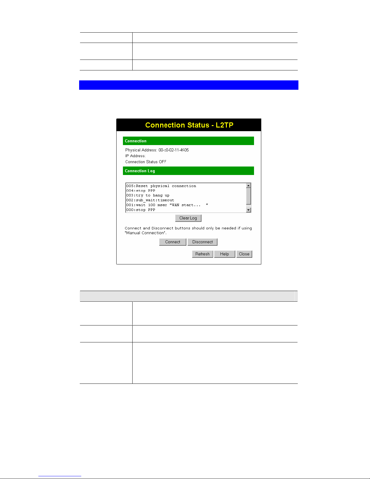
Connection Status - L2TP
If using L2TP, a screen like the following example will be displayed when the "Connection
Details" button is clicked.
Figure 29: L2TP Status Screen
Data - L2TP Screen
Connection
Physical Address
The hardware address of this device, as seen by remote devices on the
Internet. (This is different to the hardware address seen by devices on
the local LAN.)
IP Address
The IP Address of this device, as seen by Internet users. This address
is allocated by your ISP (Internet Service Provider).
Connection Status
This indicates whether or not the connection is currently established.
" If the connection does not exist, the "Connect" button can be
used to establish a connection.
" If the connection currently exists, the "Disconnect" button can be
used to break the connection.
Page 48
Wireless Router User Guide
44
Connection Log
Connection Log
" The Connection Log shows status messages relating to the
existing connection.
" The "Clear Log" button will restart the Log, while the Refresh
button will update the messages shown on screen.
Buttons
Connect
If not connected, establish a connection to your ISP.
Disconnect
If connected to your ISP, hang up the connection.
Clear Log
Delete all data currently in the Log. This will make it easier to read
new messages.
Refresh
Update the data on screen.
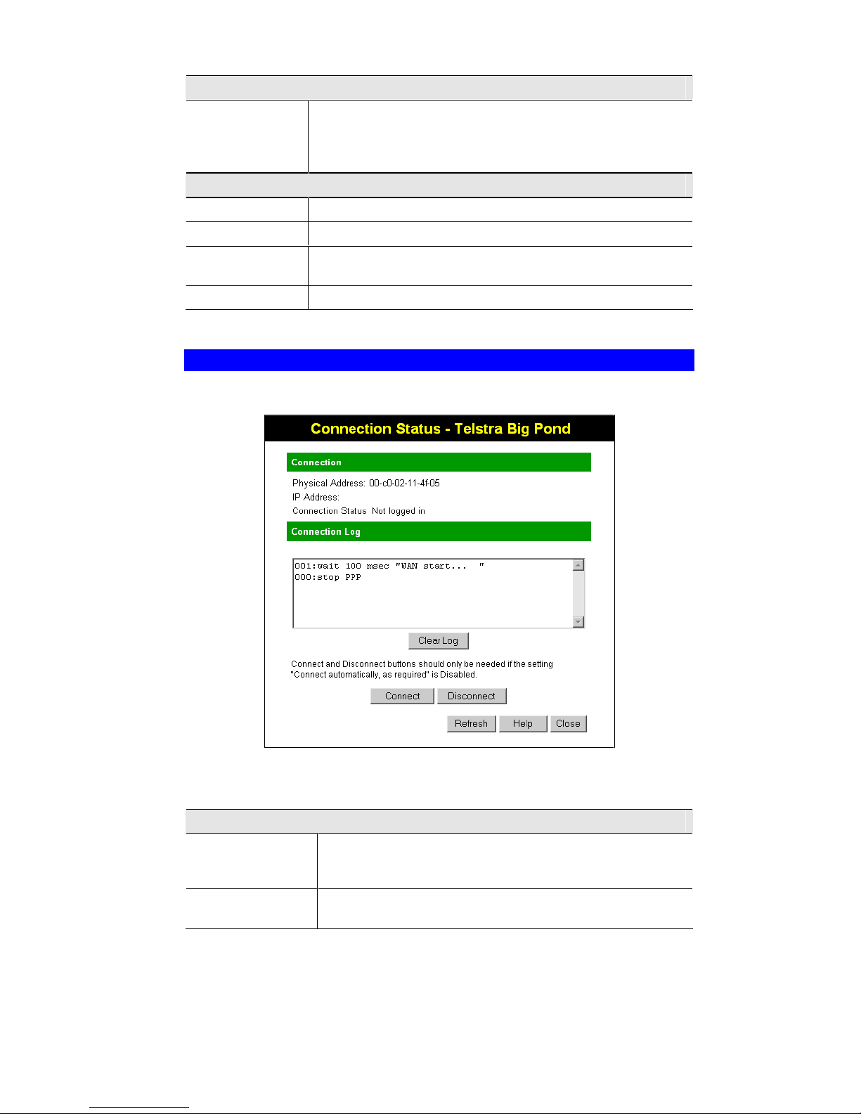
Connection Status - Telstra Big Pond
An example screen is shown below.
Figure 30: Telstra Big Pond Status Screen
Data - Big Pond Screen
Connection
Physical Address
The hardware address of this device, as seen by remote devices.
(This is different to the hardware address seen by devices on the
local LAN.)
IP Address
The IP Address of this device, as seen by Internet users. This
address is allocated by your ISP (Internet Service Provider).
Page 49
Operation and Status
45
Connection Status
This indicates whether or not the connection is currently established.
" If the connection does not exist, the "Connect" button can be
used to establish a connection.
" If the connection currently exists, the "Disconnect" button can
be used to break the connection.
" Normally, it is not necessary to use the Connect and Disconnect
buttons unless the setting "Connect automatically, as required"
is disabled.
Connection Log
Connection Log
" The Connection Log shows status messages relating to the
existing connection.
" The Clear Log button will restart the Log, while the Refresh
button will update the messages shown on screen.
Buttons
Connect
If not connected, establish a connection to Telstra Big Pond.
Disconnect
If connected to Telstra Big Pond, terminate the connection.
Clear Log
Delete all data currently in the Log. This will make it easier to read
new messages.
Refresh
Update the data on screen.
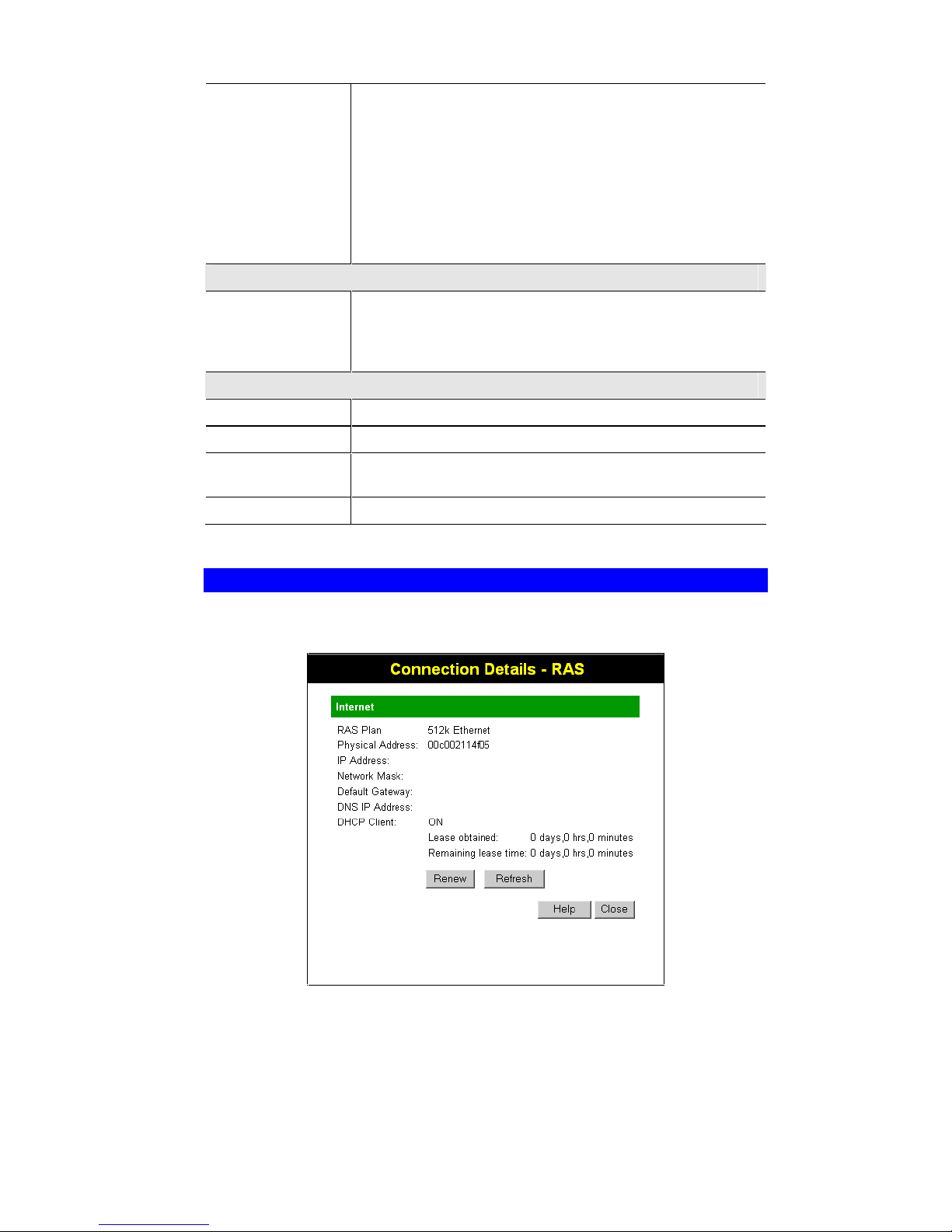
Connection Details - SingTel RAS
If using the SingTel RAS access method, a screen like the following example will be displayed
when the "Connection Details" button is clicked.
Figure 31: Connection Details - RAS
Page 50

Wireless Router User Guide
46
Data - RAS Screen
Internet
RAS Plan
The RAS Plan which is currently used.
Physical Address
The hardware address of this device, as seen by remote devices on the
Internet. (This is different to the hardware address seen by devices on
the local LAN.)
IP Address
The IP Address of this device, as seen by Internet users. This address
is allocated by your ISP (Internet Service Provider).
Network Mask
The Network Mask associated with the IP Address above.
Default Gateway
The IP Address of the remote Gateway or Router associated with the
IP Address above.
DNS IP Address
The IP Address of the Domain Name Server which is currently used.
DHCP Client
This will show "Enabled" or "Disabled", depending on whether or not
this device is functioning as a DHCP client.
If "Enabled" the "Remaining lease time" field indicates when the IP
Address allocated by the DHCP Server will expire. The lease is
automatically renewed on expiry; use the "Renew" button if you wish
to manually renew the lease immediately.
Buttons
Release/Renew
Button will display
EITHER
"Release"
OR
"Renew"
This button is only useful if the IP address shown above is allocated
automatically on connection. (Dynamic IP address). If you have a
Fixed (Static) IP address, this button has no effect.
" If the ISP's DHCP Server has NOT allocated an IP Address for
the Wireless Router, this button will say "Renew". Clicking the
"Renew" button will attempt to re-establish the connection and
obtain an IP Address from the ISP's DHCP Server.
" If an IP Address has been allocated to the Wireless Router (by
the ISP's DHCP Server), this button will say "Release". Clicking
the "Release" button will break the connection and release the IP
Address.
Refresh
Update the data shown on screen.
Page 51
Operation and Status
47
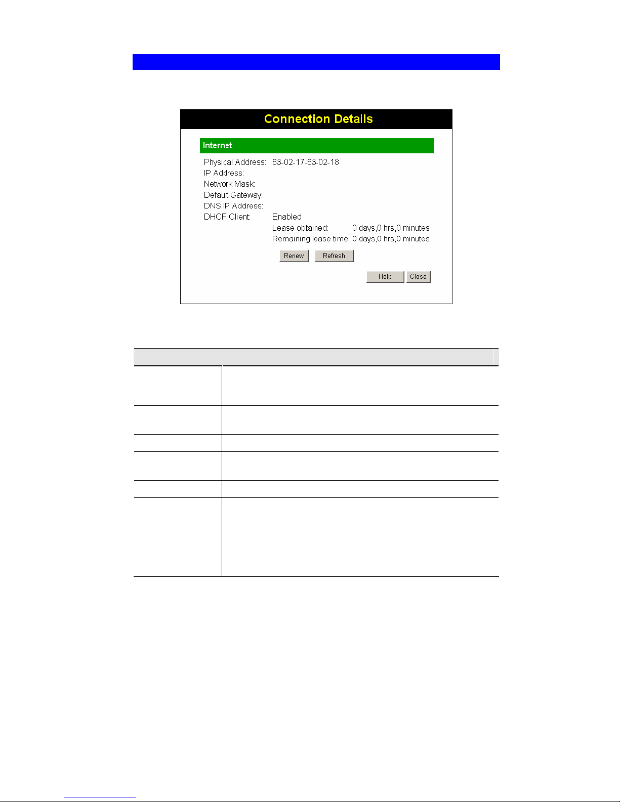
Connection Details - Fixed/Dynamic IP Address
If your access method is "Direct" (no login), a screen like the following example will be displayed when the "Connection Details" button is clicked.
Figure 32: Connection Details - Fixed/Dynamic IP Address
Data - Fixed/Dynamic IP address Screen
Internet
Physical Address
The hardware address of this device, as seen by remote devices on the
Internet. (This is different to the hardware address seen by devices on
the local LAN.)
IP Address
The IP Address of this device, as seen by Internet users. This address
is allocated by your ISP (Internet Service Provider).
Network Mask
The Network Mask associated with the IP Address above.
Default Gateway
The IP Address of the remote Gateway or Router associated with the
IP Address above.
DNS IP Address
The IP Address of the Domain Name Server which is currently used.
DHCP Client
This will show "Enabled" or "Disabled", depending on whether or not
this device is functioning as a DHCP client.
If "Enabled" the "Remaining lease time" field indicates when the IP
Address allocated by the DHCP Server will expire. The lease is
automatically renewed on expiry; use the "Renew" button if you wish
to manually renew the lease immediately.
Page 52

Wireless Router User Guide
48
Buttons
Release/Renew
Button will display
EITHER
"Release"
OR
"Renew"
This button is only useful if the IP address shown above is allocated
automatically on connection. (Dynamic IP address). If you have a
Fixed (Static) IP address, this button has no effect.
" If the ISP's DHCP Server has NOT allocated an IP Address for
the Wireless Router, this button will say "Renew". Clicking the
"Renew" button will attempt to re-establish the connection and
obtain an IP Address from the ISP's DHCP Server.
" If an IP Address has been allocated to the Wireless Router (by
the ISP's DHCP Server), this button will say "Release". Clicking
the "Release" button will break the connection and release the IP
Address.
Refresh
Update the data shown on screen.
Page 53

49
Chapter 6
Advanced Features
This Chapter explains when and how to use the Wireless Router's "Advanced"
Features.
Overview
The following advanced features are provided.
" Access Control
" Dynamic DNS
" Advanced Internet
" Communication Applications
" Special Applications
" DMZ
" Multi-DMZ
" URL Filter
" Schedule
" User Groups
" Virtual Servers
" WAN Port
Access Control
This feature is accessed by the Access Control link on the Advanced menu.
Overview
The Access Control feature allows administrators to restrict the level of Internet Access available to PCs on your LAN. With the default settings, everyone has unrestricted Internet access.
To use this feature:
1. Set the desired restrictions on the "Default" group. All PCs are in the "Default" group
unless explicitly moved to another group.
2. Set the desired restrictions on the other groups ("Group 1", "Group 2", "Group 3" and
"Group 4") as needed.
3. Assign PC to the groups as required.
Restrictions are imposed by blocking "Services", or types of
connections. All common Services are pre-defined.
If required, you can also define your own Services.
6
Page 54
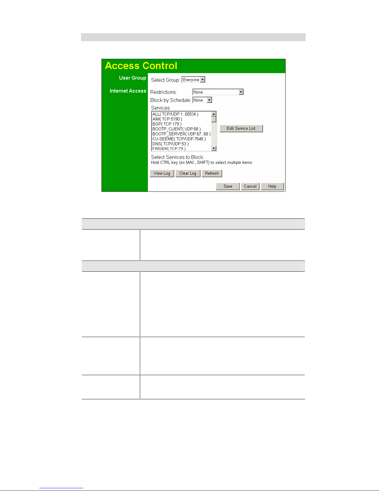
Wireless Router User Guide
50
Access Control Screen
To view this screen, select the Access Control link on the Advanced menu.
Figure 33: Access Control Screen
Data - Access Control Screen
Group
Group
Select the desired Group. The screen will update to display the
settings for the selected Group. Groups are named "Default",
"Group 1", "Group 2", "Group 3" and "Group 4", and cannot be renamed.
Internet Access
Restrictions
Select the desired options for the current group:
" None - Nothing is blocked. Use this to create the least restric-
tive group.
" Block all Internet access - All traffic via the WAN port is
blocked. Use this to create the most restrictive group.
" Block selected Services - You can select which Services are to
block. Use this to gain fine control over the Internet access for
a group.
Block by Schedule
If Internet access is being blocked, you can choose to apply the
blocking only during scheduled times. (If access is not blocked, no
Scheduling is possible, and this setting has no effect.)
You can define or modify the Schedule using the Schedule option
on the Advanced menu.
Services
This lists all defined Services. Select the Services you wish to
block. To select multiple services, hold the CTRL key while selecting. (On the Macintosh, hold the SHIFT key rather than CTRL.)
Page 55

Advanced Features
51
Edit Service List
Button
If you wish to define additional Services, or manage the Service list,
click this button to open the "Services" screen.
Buttons
Edit Service List
If you wish to define additional Services, or manage the Service list,
click this button to open the "Services" screen.
Save
Save the data on screen.
Cancel
Reverse any changes made since the last "Save".
View Log
Click this to open a sub-window where you can view the "Access
Control" log. This log shows attempted Internet accesses which
have been blocked by the Access Control feature.
Clear Log
Click this to clear and restart the "Access Control" log, making new
entries easier to read.
Refresh
Update the data on screen.
Page 56
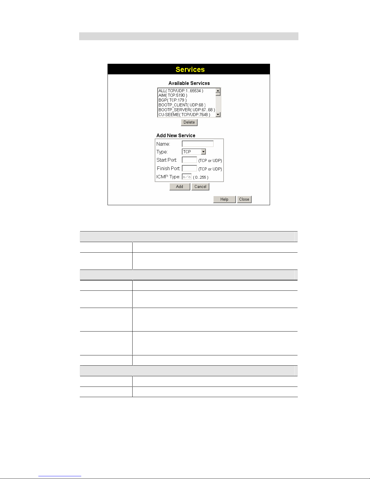
Wireless Router User Guide
52
Services Screen
This screen is displayed when the Edit Service List button on the Access Control screen is
clicked.
Figure 34: Access Control - Services
Data - Services Screen
Available Services
Available Services
This lists all the available services.
"Delete" button
Use this to delete any Service you have added. Pre-defined Services
can not be deleted.
Add New Service
Name
Enter a descriptive name to identify this service.
Type
Select the protocol (TCP, UDP, ICMP) used to the remote system or
service.
Start Port
For TCP and UDP Services, enter the beginning of the range of port
numbers used by the service. If the service uses a single port number,
enter it in both the "Start" and "Finish" fields.
Finish Port
For TCP and UDP Services, enter the end of the range of port numbers used by the service. If the service uses a single port number,
enter it in both the "Start" and "Finish" fields.
ICMP Type
For ICMP Services, enter the type number of the required service.
Buttons
Delete
Delete the selected service from the list.
Save
Add a new entry to the Service list, using the data shown in the "Add
Page 57

Advanced Features
53
New Service" area on screen.
Cancel
Clear the " Add New Service " area, ready for entering data for a new
Service.
Access Control Log
To check the operation of the Access Control feature, an Access Control Log is provided. Click
the View Log button on the Access Control screen to view this log.
This log shows attempted Internet accesses which have been blocked by the Access Control
function.
Data shown in this log is as follows:
Date/Time
Date and Time of the attempted access.
Name
If known, the name of the PC whose access was blocked.
Source IP address
The IP Address of the PC or device whose access request was
blocked
MAC address
The hardware or physical address of the PC or device whose access
request was blocked
Destination
The destination URL or IP address
Page 58
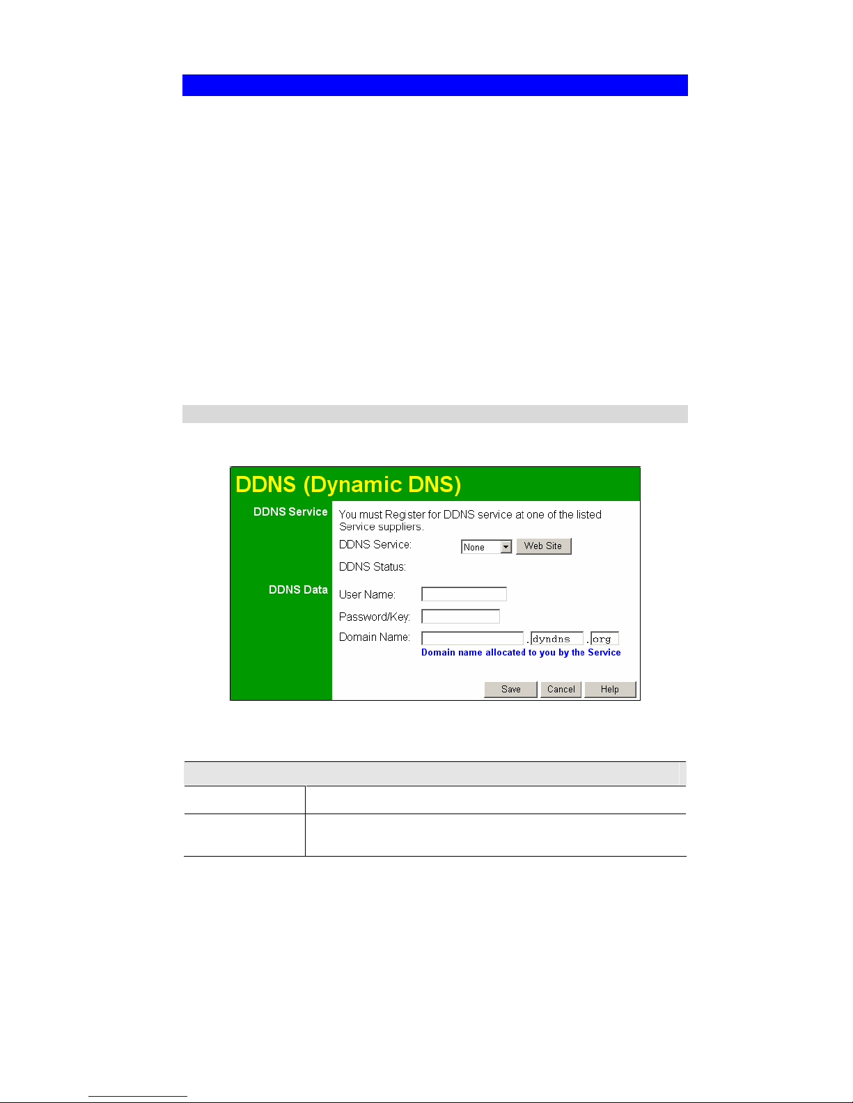
Wireless Router User Guide
54
Dynamic DNS (Domain Name Server)
This free service is very useful when combined with the Virtual Server feature. It allows Internet users to connect to your Virtual Servers using a URL, rather than an IP Address.
This also solves the problem of having a dynamic IP address. With a dynamic IP address, your
IP address may change whenever you connect, which makes it difficult to connect to you.
The Service works as follows:
1. You must register for the service at one of the listed DDNS Service Providers.
2. After registration, follow the service provider's procedure to request a Domain Name and
have it allocated to you.
3. Enter your DDNS data on the Wireless Router's DDNS screen.
4. The Wireless Router will then automatically ensure that your current IP Address is re-
corded at the DDNS server.
If the DDNS Service provides software to perform this "IP address update"; you should
disable the "Update" function, or not use the software at all.
5. From the Internet, users will be able to connect to your Virtual Servers (or DMZ PC) using
your Domain Name.
Dynamic DNS Screen
Select Advanced on the main menu, then Dynamic DNS, to see a screen like the following:
Figure 35: DDNS Screen
Data - Dynamic DNS Screen
DDNS Service
DDNS Service
Select the desired DDNS Service provider.
Web Site
Button
Click this button to open a new window and connect to the Web site
for the selected DDNS service provider.
Page 59

Advanced Features
55
DDNS Status
" This message is returned by the DDNS Server.
" Normally, this message should be something like "Update suc-
cessful" (current IP address was updated on the DDNS server).
" If the message is "No host", this indicates the host name entered
was not allocated to you. If you see this or some other error message, you need to contact the DDNS Service and correct the
problem.
DDNS Data
User Name
Enter your Username for the DDNS Service.
Password/Key
Enter your current password for the DDNS Service.
Domain Name
Enter the domain name allocated to you by the DDNS Service. If you
have more than one name, enter the name you wish to use.
Page 60
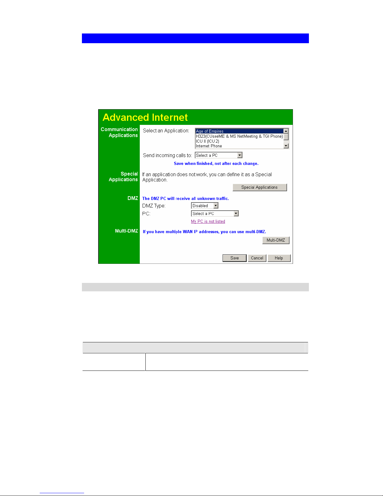
Wireless Router User Guide
56
Advanced Internet Screen
This screen allows configuration of all advanced features relating to Internet access.
" Communication Applications
" Special Applications
" DMZ
" Multi-DMZ
An example screen is shown below.
Figure 36: Internet Screen
Communication Applications
Most applications are supported transparently by the Broadband Router. But sometimes it is not
clear which PC should receive an incoming connection. This problem could arise with the
Communication Applications listed on this screen.
If this problem arises, you can use this screen to set which PC should receive an incoming
connection, as described below.
Communication Applications
Select an Application
This lists applications which may generate incoming connections,
where the destination PC (on your local LAN) is unknown.
Page 61
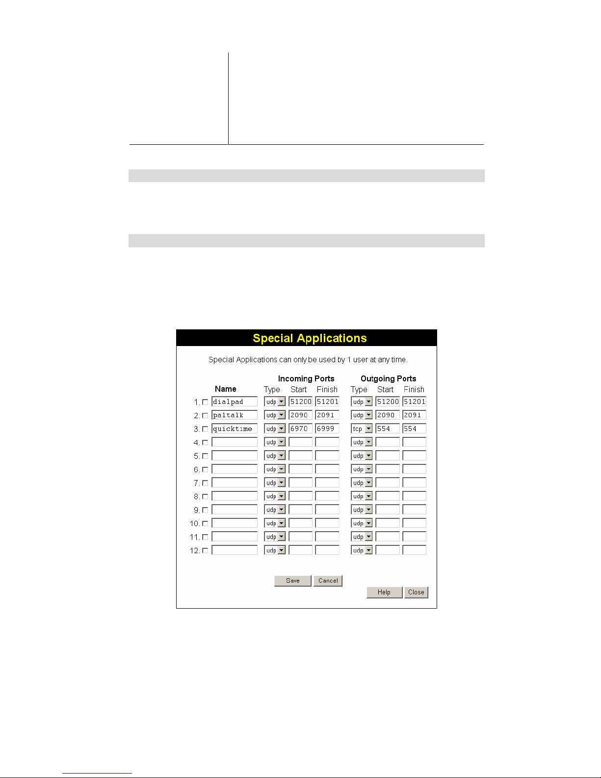
Advanced Features
57
Send incoming calls to
This lists the PCs on your LAN.
" If necessary, you can add PCs manually, using the "PC
Database" option on the advanced menu.
" For each application listed above, you can choose a destina-
tion PC.
" There is no need to "Save" after each change; you can set the
destination PC for each application, then click "Save".
Special Applications
If you use Internet applications which use non-standard connections or port numbers, you may
find that they do not function correctly because they are blocked by the Wireless Router's
firewall. In this case, you can define the application as a "Special Application".
Special Applications Screen
This screen can be reached by clicking the Special Applications button on the Internet screen.
You can then define your Special Applications. You will need detailed information about the
application; this is normally available from the supplier of the application.
Also, note that the terms "Incoming" and "Outgoing" on this screen refer to traffic from the
client (PC) viewpoint
Figure 37: Special Applications Screen
Page 62
Wireless Router User Guide
58
Data - Special Applications Screen
Checkbox
Use this to Enable or Disable this Special Application as required.
Name
Enter a descriptive name to identify this Special Application.
Incoming
Ports
" Type - Select the protocol (TCP or UDP) used when you receive data
from the special application or service. (Note: Some applications use
different protocols for outgoing and incoming data).
" Start - Enter the beginning of the range of port numbers used by the
application server, for data you receive. If the application uses a single
port number, enter it in both the "Start" and "Finish" fields.
" Finish - Enter the end of the range of port numbers used by the applica-
tion server, for data you receive.
Outgoing
Ports
" Type - Select the protocol (TCP or UDP) used when you send data to
the remote system or service.
" Start - Enter the beginning of the range of port numbers used by the
application server, for data you send to it. If the application uses a single
port number, enter it in both the "Start" and "Finish" fields.
" Finish - Enter the end of the range of port numbers used by the applica-
tion server, for data you send to it. If the application uses a single port
number, enter it in both the "Start" and "Finish" fields.
Using a Special Application
" Configure the Special Applications screen as required.
" On your PC, use the application normally. Remember that only one (1) PC can use each
Special application at any time. Also, when 1 PC is finished using a particular Special Ap-
plication, there may need to be a "Time-out" before another PC can use the same Special
Application. The "Time-out" period may be up to 3 minutes.
If an application still cannot function correctly,
try using the "DMZ" feature.
DMZ
" The "DMZ" PC will receive all "Unknown" connections and data. This feature is normally
used with applications which do not usually work when behind a Firewall.
" The DMZ PC is effectively outside the Firewall, making it more vulnerable to attacks. For
this reason, you should only enable the DMZ feature when required.
" If Enabled, you must select the PC to be used as the "DMZ" PC.
Select the desired option
" Disabled - DMZ is disabled.
" Enabled- The selected PC is a standard PC on your LAN, but it will receive any "un-
known" connections and data, as described above.
Page 63
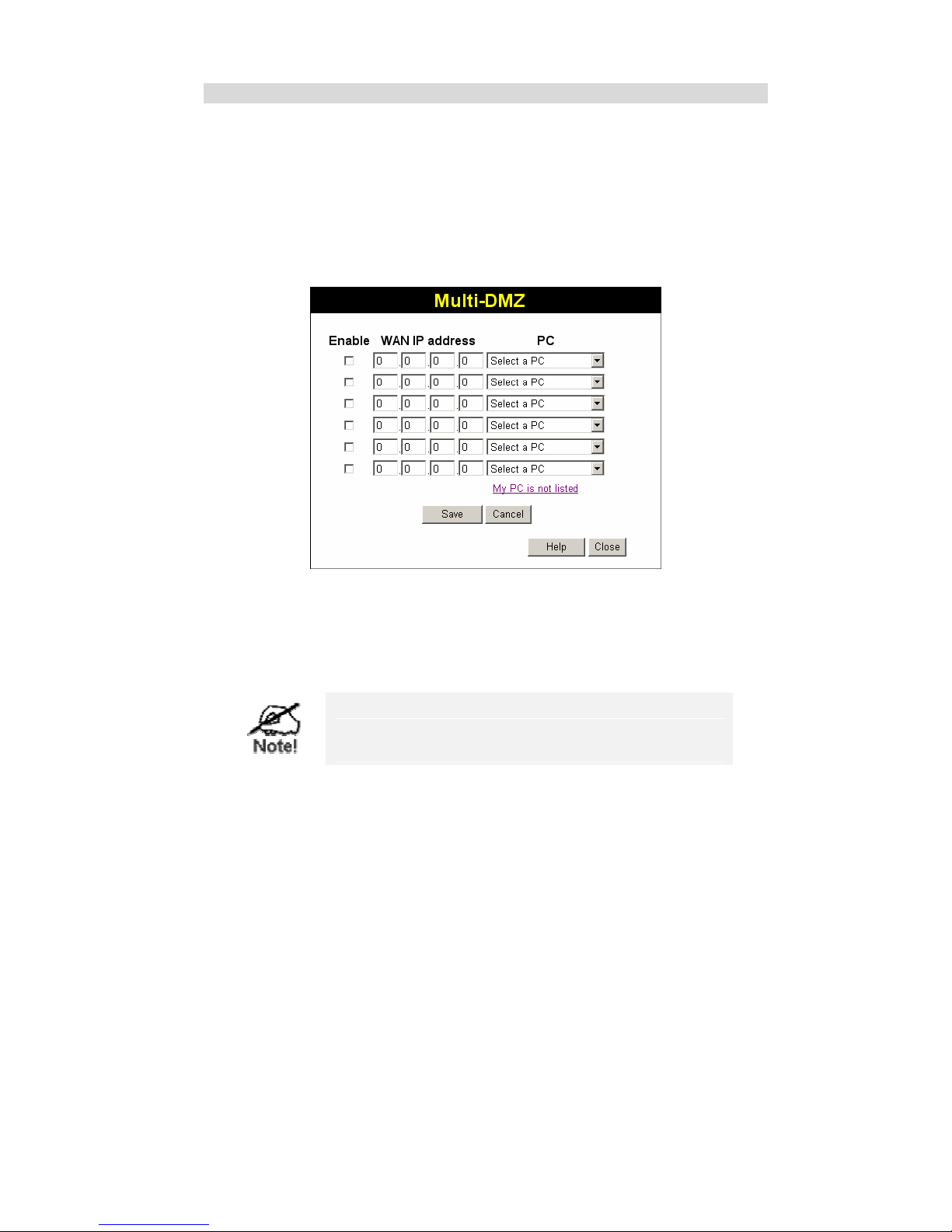
Advanced Features
59
Multi-DMZ
This feature is only available if your ISP has allocated you multiple Internet IP addresses.
If you have multiple Internet IP addresses, you can assign one DMZ PC for each Internet IP
address.
" The "DMZ PC" will receive all "Unknown" connections and data received for the Internet
IP address associated with it.
" All outgoing traffic from the DMZ PC will be assigned the WAN IP address associated
with it, rather than the shared IP address on the WAN port. Note that ONLY the DMZ PC
will use the WAN (Internet) IP address you enter on this screen.
To use this feature:
" Enter an IP address allocated to you by your ISP into the WAN IP address field.
" Select the PC to be the DMZ PC for traffic sent to this IP address.
" Enable this DMZ.
The "DMZ PC" is effectively outside the Firewall, making it more vulnerable to attacks. For this reason, you
should only enable the DMZ feature when required.
Page 64
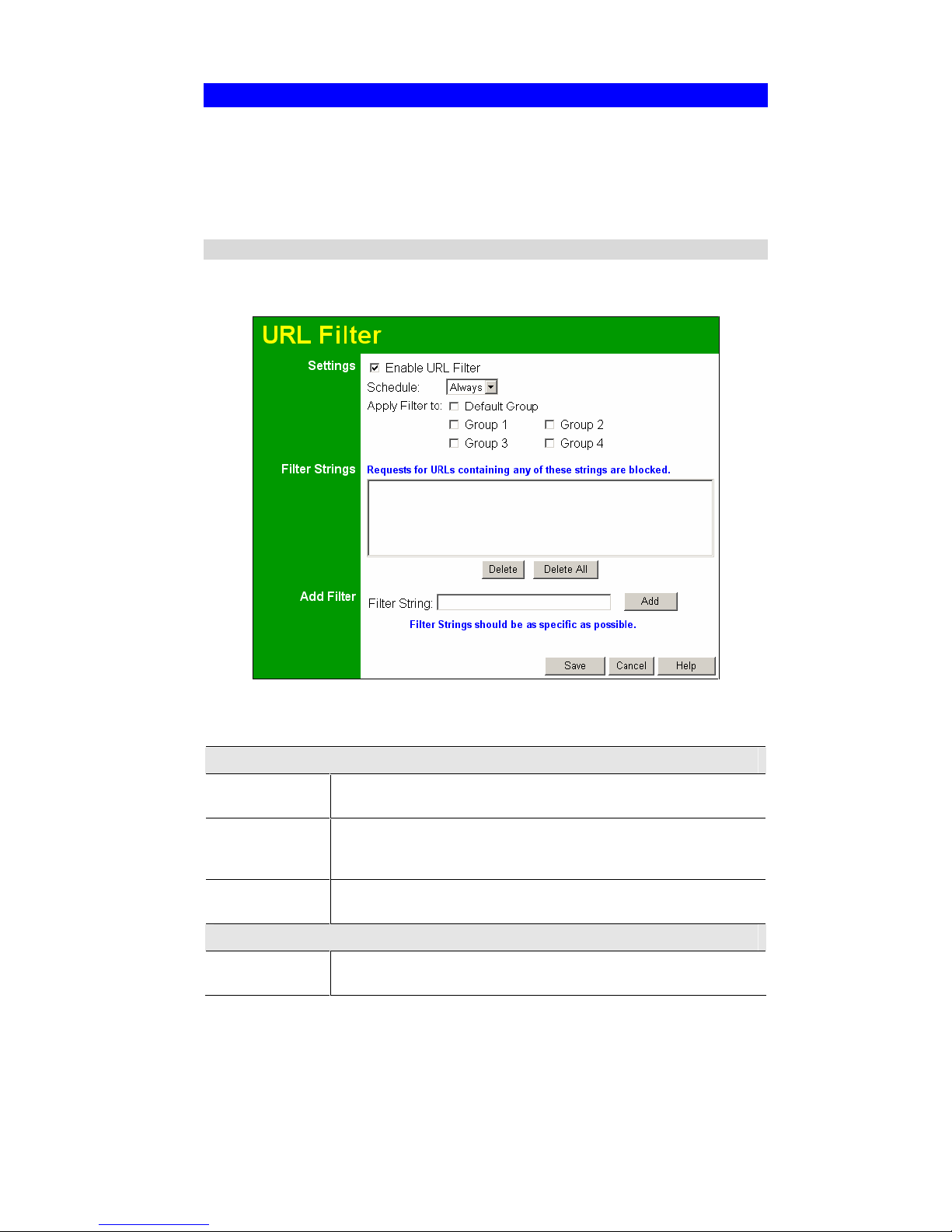
Wireless Router User Guide
60
URL Filter
The URL Filter allows you to block access to undesirable Web site
" To use this feature, you must define "filter strings". If the "filter string" appears in a re-
quested URL, the request is blocked.
" Enabling the URL Filter also affects the Internet Access Log. If Enabled, the "Destination"
field in the log will display the URL. Otherwise, it will display the IP Address.
URL Filter Screen
Click the "URL Filter" on the Advanced screen to access the URL Filter screen. An example
screen is shown below.
Figure 38: URL Filter Screen
Data - URL Filter Screen
Settings
Enable
This lists any existing entries. If you have not entered any values, this
list will be empty.
Schedule
If you always want filtering to be active, select "Always".
Otherwise, select the schedule to use. You can define the schedule
using the Schedule menu option, on the Advanced menu.
Apply Filter to
Select the groups you wish the filter to apply to. Group membership
can be set on the "User Groups" screen, on the "Administration" menu.
Filter Strings
Filter Strings
This lists any existing entries. If you have not entered any values, this
list will be empty.
Page 65
Advanced Features
61
Delete
Use this to delete the selected entry or entries, as required. Multiple
entries can be selected by holding down the CTRL key while selecting.
(On the Macintosh, hold the SHIFT key while selecting.)
Delete All
Use this button to delete all entries, if required.
Add Filter
Filter String
To add an entry to the list, enter it here, and click the "Add" button.
An entry may be a Domain name (e.g. www.trash.com) or simply a
string (e.g. ads/ )
Any URL which contains ANY entry ANYWHERE in the URL will be
blocked.
Add
Button
Use this to add the entry in the "Filter String" above to the list.
Add Filter
Delete/Delete All
Use these buttons to delete the selected entry or all entries, as required.
Multiple entries can be selected by holding down the CTRL key while
selecting. (On the Macintosh, hold the SHIFT key while selecting.)
Add
Use this to add the current Filter String to the site list.
Page 66
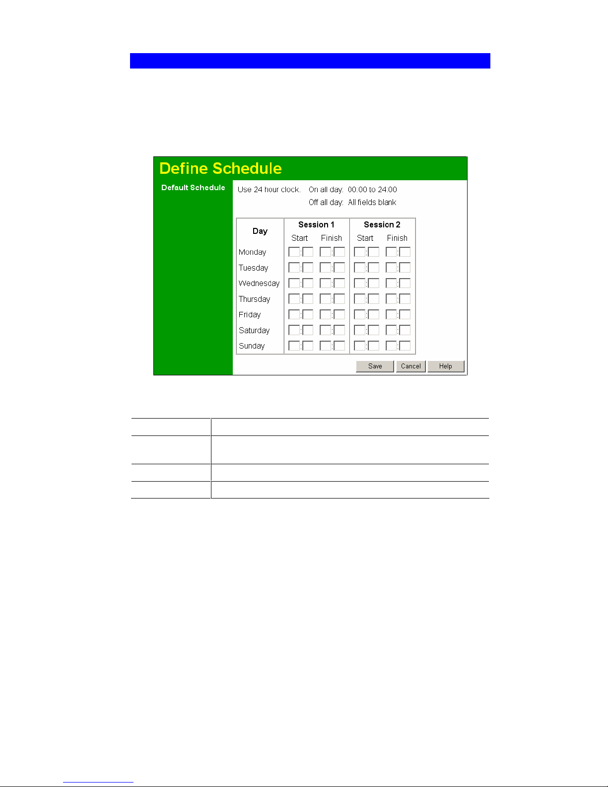
Wireless Router User Guide
62
Define Schedule
The schedule can be used for the Access Control and URL Filter features.
" Two (2) separate sessions or periods can be defined.
" Times must be entered using a 24 hr clock.
" If the time for a particular day is blank, no action will be performed.
Figure 39: Define Schedule Screen
Data – Define Schedule Screen
Day
Each day of the week can scheduled independently.
Session 1
Session 2
Two (2) separate sessions or periods can be defined. Session 2 can be
left blank if not required.
Start Time
Enter the start using a 24 hr clock.
Finish Time
Enter the finish time using a 24 hr clock.
Page 67
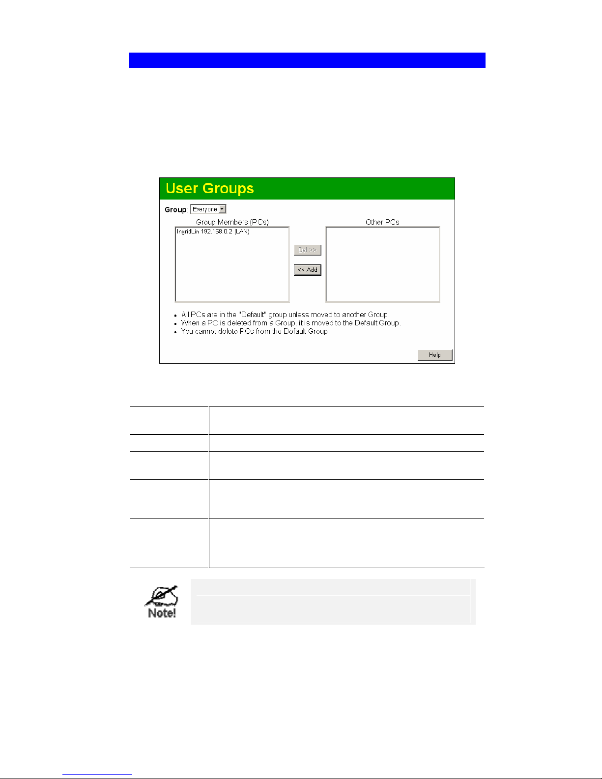
Advanced Features
63
User Groups
User Groups are used by the Access Control and the URL Filter features.
" Groups are pre-named "Default", "Group 1", "Group 2", "Group 3" and "Group 4", and
cannot be renamed.
" All PCs are in the "Default" group, unless moved to another group.
" A PC can be a member of 1 group only.
" PCs must be in the "PC Database". If required, you can manually add PCs to the PC
Database, using the PC Database option on the Administration menu.
Figure 40: User Groups Screen
Data – User Groups Screen
Group List
Select the desired Group. The screen will update to display the PCs for
the selected Group.
Group Members
This lists all PCs, which are currently members of the selected group.
Other PCs
This lists all other PCs – those, which are not currently members of the
selected group.
Del >>
Use this button to remove members from the current Group.
Select the members you wish to delete from this group, and click this
button. (Members can not be deleted from the "Default" group.)
<< Add
Use this button to add members to the current Group.
In the "Other PCs" list, select the members you wish to add to this
group, and click this button. The PCs will be moved from their existing
group to the current group.
PCs not assigned to any group will be in the "Default" group.
PCs deleted from any other Group will be added to the "Default" group.
Page 68
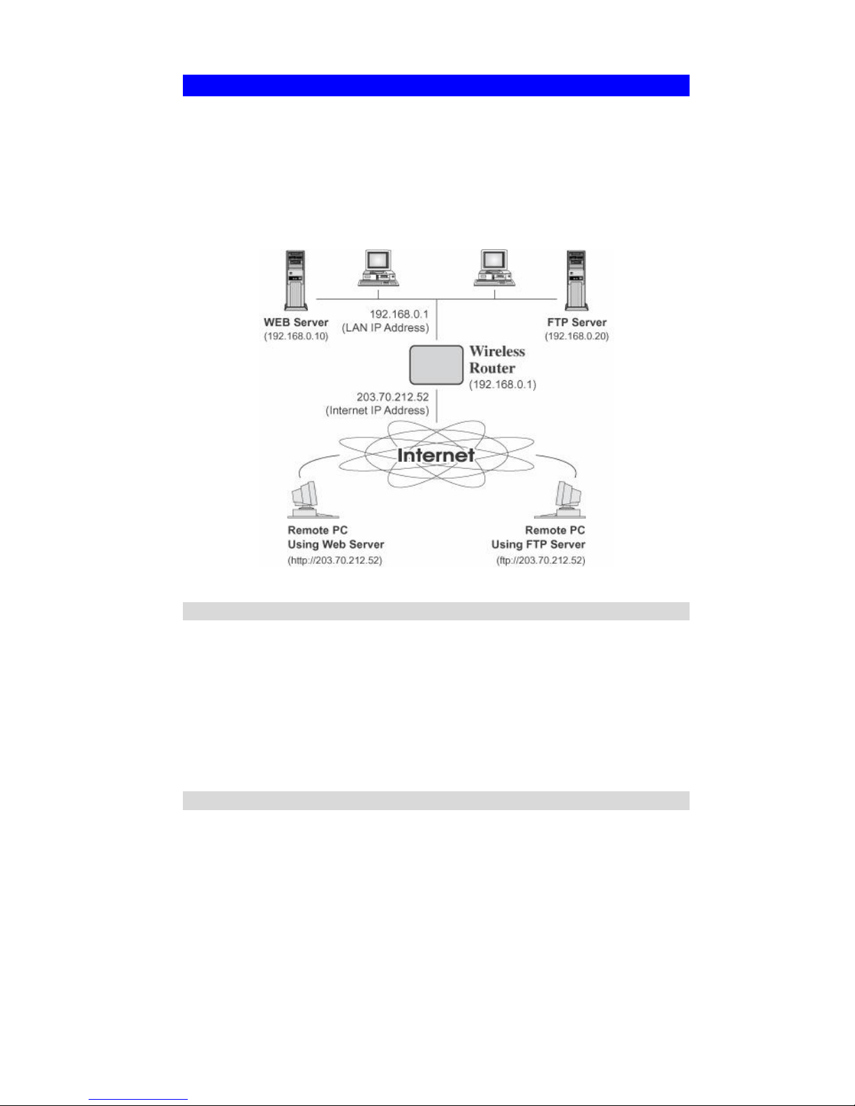
Wireless Router User Guide
64
Virtual Servers
This feature, sometimes called Port Forwarding, allows you to make Servers on your LAN
accessible to Internet users. Normally, Internet users would not be able to access a server on
your LAN because:
" Your Server does not have a valid external IP Address.
" Attempts to connect to devices on your LAN are blocked by the firewall in this device.
The "Virtual Server" feature solves these problems and allows Internet users to connect to your
servers, as illustrated below.
Figure 41: Virtual Servers
IP Address seen by Internet Users
Note that, in this illustration, both Internet users are connecting to the same IP Address, but
using different protocols.
To Internet users, all virtual Servers on your LAN have the same IP Address.
This IP Address is allocated by your ISP.
This address should be static, rather than dynamic, to make it easier for Internet users to connect to your Servers.
However, you can use the DDNS (Dynamic DNS) feature to allow users to connect to your
Virtual Servers using a URL, instead of an IP Address.
Virtual Servers Screen
The Virtual Servers screen is reached by the Virtual Servers link on the Advanced screen. An
example screen is shown below.
Page 69
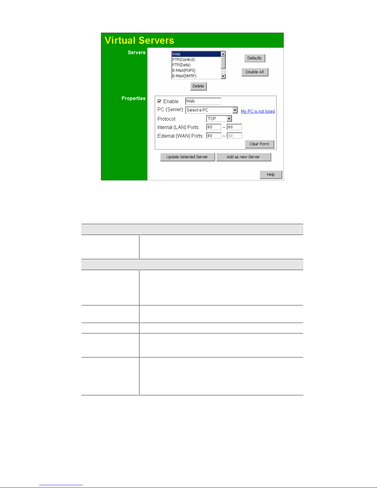
Advanced Features
65
Figure 42: Virtual Servers Screen
This screen lists a number of pre-defined Servers, and allows you to define your own Servers.
Details of the selected Server are shown in the "Properties" area.
Data - Virtual Servers Screen
Servers
Servers
This lists a number of pre-defined Servers, plus any Servers you
have defined. Details of the selected Server are shown in the "Properties" area.
Properties
Enable
Use this to Enable or Disable support for this Server, as required.
" If Enabled, any incoming connections will be forwarded to the
selected PC.
" If Disabled, any incoming connection attempts will be blocked.
PC (Server)
Select the PC for this Server. The PC must be running the appropriate Server software.
Protocol
Select the protocol (TCP or UDP) used by the Server.
Internal Ports
Enter the range of port numbers which the Server software is
configured to use. If only 1 port number is required, enter it in both
the start and finish fields.
External Ports
The port numbers used by Internet users when connecting to the
Server. These are normally the same as the Internal Port Numbers.
If it is different, this device will perform a "mapping" or "translation" function, allowing the server to use one port address, while
clients use a different port address.
Page 70
Wireless Router User Guide
66
Buttons
Defaults
This will delete any Servers you have defined, and set the predefined Servers to use their default port numbers.
Disable All
This will cause the "Enable" setting of all Virtual Servers to be set
OFF.
Update Selected
Server
Update the current Virtual Server entry, using the data shown in the
"Properties" area on screen.
Add as new Server
Add a new entry to the Virtual Server list, using the data shown in
the "Properties" area on screen. The entry selected in the list is
ignored, and has no effect.
Delete
Delete the current Virtual Server entry. Note that the pre-defined
Servers can not be deleted. Only Servers you have defined yourself
can be deleted.
Clear Form
Clear all data from the "Properties" area, ready for input of a new
Virtual Server entry.
For each entry, the PC must be running the
appropriate Server software.
Defining your own Virtual Servers
If the type of Server you wish to use is not listed on the Virtual Servers screen, you can define
and manage your own Servers:
Create a new Server:
1. Click "Clear Form"
2. Enter the required data, as described above.
3. Click "Add".
4. The new Server will now appear in the list.
Modify (Edit) a Server:
1. Select the desired Server from the list
2. Make any desired changes (for example, change the
Enable/Disable setting).
3. Click "Update" to save changes to the selected Server.
Delete a Server:
1. Select the entry from the list.
2. Click "Delete".
Note: You can only delete Servers you have defined. Pre-
defined Server cannot be deleted.
From the Internet, ALL Virtual Servers have the IP
Address allocated by your ISP.
Page 71

Advanced Features
67
Connecting to the Virtual Servers
Once configured, anyone on the Internet can connect to your Virtual Servers. They must use the
Internet IP Address (the IP Address allocated to you by your ISP).
e.g.
http://203.70.212.52
ftp://203.70.212.52
It is more convenient if you are using a Fixed IP Address from your ISP, rather than Dynamic.
However, you can use the Dynamic DNS feature, described in the following section, to allow
users to connect to your Virtual Servers using a URL, rather than an IP Address.
Page 72
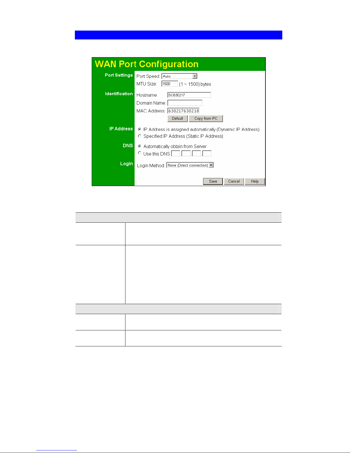
Wireless Router User Guide
68
WAN Port Configuration
The WAN Port option is on the Advanced menu.
Figure 43: WAN Port Screen
Data – WAN Port Screen
Port Settings
Port Speed
Normally, this can be left at "Automatic". If the device attached to the
WAN Port has problems making a connection, you can select the
setting required or preferred by the other device.
MTU Size
" MTU (Maximum Transmission Unit) value should only be
changed if advised to do so by Technical Support.
" Enter a value between 1 and 1500.
" This device will still auto-negotiate with the remote server, to set
the MTU size. The smaller of the 2 values (auto-negotiated, or
entered here) will be used.
" For direct connections (not PPPoE or PPTP), the MTU used is
always 1500.
Identification
Hostname
Normally, there is no need to change the default name, but if your ISP
requests that you use a particular Hostname, enter it here.
Domain Name
If your ISP provided a domain name, enter it here. Otherwise, this
may be left blank.
Page 73

Advanced Features
69
WAN Port MAC
Address
Also called Network Adapter Address or Physical Address. This is a
low-level identifier, as seen from the WAN port.
Normally there is no need to change this, but some ISPs require a
particular value, often that of the PC initially used for Internet access.
You can use the Copy from PC button to copy your PC's address into
this field, the Default button to insert the default value, or enter a
value directly.
IP Address
Automatic
Also called Dynamic IP Address. This is the default, and the most
common.
Leave this selected if your ISP allocates an IP Address to the Wireless Router upon connection.
Specified IP
Address
Also called Static IP Address. Select this if your ISP has allocated
you a fixed IP Address. If this option is selected, the following data
must be entered.
" IP Address
The IP Address allocated by the ISP.
" Network Mask (Not required for PPPoE)
This is also supplied by your ISP. It must be compatible with the
IP Address above.
" Gateway IP Address (Not required for PPPoE)
The address of the router or gateway, as supplied by your ISP.
DNS
Automatically
obtain from Serve
The DNS (Domain Name Server) address will be obtained automatically from your ISP's server.
Note that if using a fixed IP address, with no login (login is set to
"None"), and then no Server is used, so this option cannot be used.
Use this DNS
If this option is selected, you must enter the IP address of the DNS
(Domain Name Server) you wish to use.
Page 74

Wireless Router User Guide
70
Login
Login Method
If your ISP does not use a login method (username, password) for
Internet access, leave this at the default value None (Direct connec-
tion). Otherwise, check the documentation from your ISP, select the
login method used, and enter the required data.
" PPPoE - this is the most common login method, widely used
with DSL modems. Normally, your ISP will have provided some
software to connect and login. This software is no longer required, and should not be used.
" PPPoE (Unnumbered IP) - this can only be used if your ISP
supports this system, and has allocated you multiple IP addresses.
If selected, you must also select "Specified IP Address" above
and enter one of the IP addresses allocated to you by your ISP.
The other IP addresses must be assigned to PCs on your LAN.
" PPTP - this is mainly used in Europe. You need to know the
PPTP Server address as well as your name and password.
" L2TP - this is not widely used. You need to know the PPTP
Server address as well as your name and password.
" Big Pond Cable - for Australia only.
" SingTel RAS - for Singapore only.
Login User Name
The User Name (or account name) provided by your ISP.
Login Password
Enter the password for the login name above.
RAS Plan
For SingTel customers only, select the RAS plan you are on.
Server Address
This is not required for PPPoE or SingTel RAS.
For PPTP, L2TP and BPA, enter the Server address as provided by
your ISP.
Connection
Behavior
Select the desired option:
" Automatic Connect/Disconnect
An Internet connection is automatically made when required, and
disconnected when idle for the time period specified by the
"Auto-disconnect Idle Time-out".
" Manual Connect/Disconnect
You must manually establish and terminate the connection.
" Keep alive (maintain connection)
The connection will never be disconnected by this device. If disconnected by your ISP, the connection will be re-established
immediately. (However, this does not ensure that your Internet IP
address will remain unchanged.)
Auto-disconnect
Idle Time-out
This field has no effect unless using the Automatic Connect/Disconnect setting.
If using this setting, enter the desired idle time-out period (in
minutes). After the connection to your ISP has been idle for this
time period, the connection will be terminated.
Buttons
Default
Inserts the default MAC address into the MAC address field. You
must click "Save" to actually change the address used.
Page 75

Advanced Features
71
Copy from PC
Inserts the MAC address from your PC into the MAC address field.
You must click "Save" to actually change the address used.
Save
Save your changes to the Broadband Router.
Cancel
Reverse any changes made since the last "Save".
Page 76

72
Chapter 7
Advanced Administration
This Chapter explains the settings available via the "Administration" section
of the menu.
Overview
Normally, it is not necessary to use these screens, or change any settings. These screens and
settings are provided to deal with non-standard situations, or to provide additional options for
advanced users.
The available settings and features are:
Config File
Backup or restore the configuration file for the Wireless Router This file
contains all the configuration data.
Logs
View or clear all logs, set E-Mailing of log files.
Network
Diagnostics
Ping, DNS Lookup.
Options
Various options, such as backup DNS and UPnP.
PC Database
This is the list of PCs shown when you select the "DMZ PC" or a "Virtual Server". This database is maintained automatically, but you can add
and delete entries for PCs which use a Fixed (Static) IP Address.
Remote
Administration
Allow settings to be changed from the Internet.
Routing
Only required if your LAN has other Routers or Gateways.
Security
Firewall and other security-related settings. Normally, the default settings
do not need to be changed.
Firmware
Upgrade
Upgrade the Firmware (software) installed in your Broadband Router.
7
Page 77
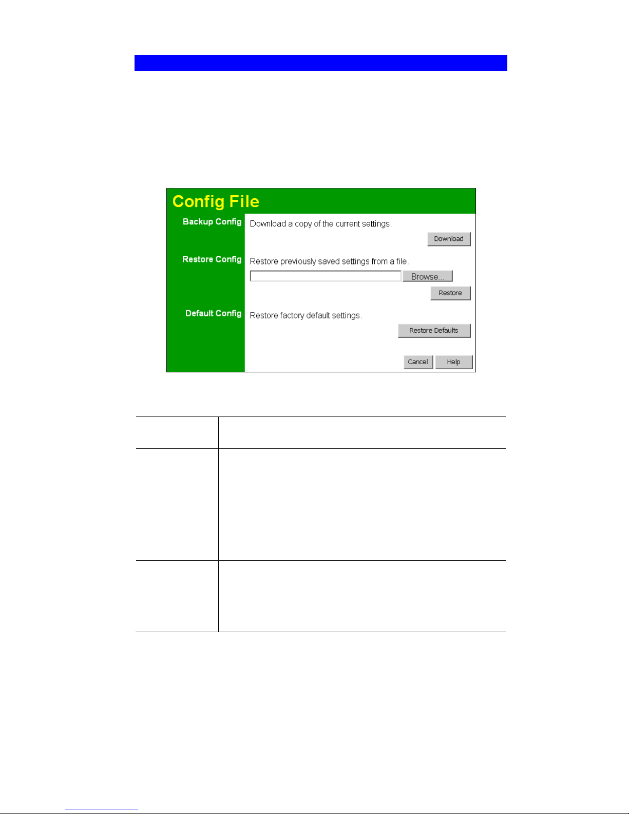
Advanced Administration
73
Config File
This feature allows you to download the current settings from the Wireless Router, and save
them to a file on your PC.
You can restore a previously-downloaded configuration file to the Wireless Router, by uploading it to the Wireless Router.
This screen also allows you to set the Wireless Router back to its factory default configuration.
Any existing settings will be deleted.
An example Config File screen is shown below.
Figure 44: Config Screen
Data - Config File Screen
Backup Config
Use this to download a copy of the current configuration, and store the
file on your PC. Click Download to start the download.
Restore Config
This allows you to restore a previously-saved configuration file back to
the Wireless Router
Click Browse to select the configuration file, then click Restore to
upload the configuration file.
WARNING !
Uploading a configuration file will destroy (overwrite) ALL of the
existing settings.
Default Config
Clicking the Restore Defaults button will reset the Wireless Router to
its factory default settings.
WARNING !
This will delete ALL of the existing settings.
Page 78
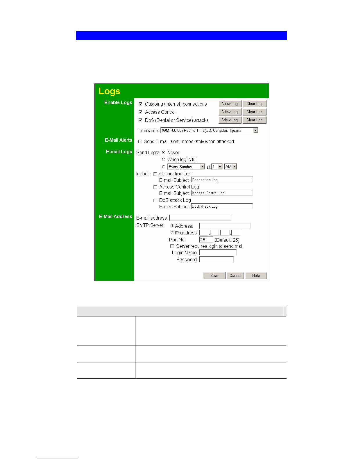
Wireless Router User Guide
74
Logs
The Logs record various types of activity on the Wireless Router This data is useful for troubleshooting, but enabling all logs will generate a large amount of data and adversely affect
performance.
Since only a limited amount of log data can be stored in the Wireless Router, log data can also
be E-mailed to your PC.
Figure 45: Logs Screen
Data - Logs Screen
Enable Logs
Outgoing
Connections
If selected, Outgoing Internet connections are logged. Normally,
the (Internet) "Destination" will be shown as an IP address. But if
the "URL Filter" is enabled, the "Destination" will be shown as a
URL.
Access Control
If enabled, the log will include attempted outgoing connections
which have been blocked by the "Access Control" feature.
DoS Attacks
If enabled, this log will show details of DoS (Denial of Service)
attacks which have been blocked by the built-in Firewall.
Page 79

Advanced Administration
75
Timezone
Select the correct Timezone for your location. This is required for
the date/time shown on the logs to be correct.
View Log Button
Use this to view each log, as required.
Clear Log Button
Use this to restart the required log. This makes it easier to read the
latest entries.
E-Mail Alerts
Send E-mail alert..
If enabled, an E-mail will be sent immediately if a DoS (Denial of
Service) attack is detected. If enabled, the E-mail address information (below) must be provided.
E-Mail Logs
Send Logs
Select the desired option for sending the log by E-mail.
" Never - E-mailing of Logs is disabled.
" When log is full - The time is not fixed. The log will be sent
when the log is full, which will depend on the volume of traffic.
" Every day, Every Monday ... - The log is sent on the
interval specified.
" If "Every day" is selected, the log is sent at the time
specified.
" If the day is specified, the log is sent once per week, on
the specified day.
" Select the time of day you wish the E-mail to be sent.
" If the log is full before the time specified to send it, it
will be sent regardless.
Include
Enabled the logs you wish to send. If no checkboxes are enabled,
no logs will be sent.
For each type of log, you can set the "Subject" field which is
displayed in your inbox when you receive the mail.
E-Mail Address
E-mail Address
Enter the E-mail address the Log is to be sent to. The E-mail will
also show this address as the Sender's address.
Subject
Enter the text string to be shown in the "Subject" field for the Email.
SMTP Server
Address
Enter the address (domain name) or IP address of the SMTP
(Simple Mail Transport Protocol) Server you use for outgoing Email.
Port No.
Enter the port number used to connect to the SMTP Server. The
default value is 25.
Server requires
Login to send mail
If your SMTP Server requires you to login in order to send mail:
" Check the setting "Server requires login to send mail"
" Enter your Login Name and Password for the SMTP Server
in the fields provided.
Page 80
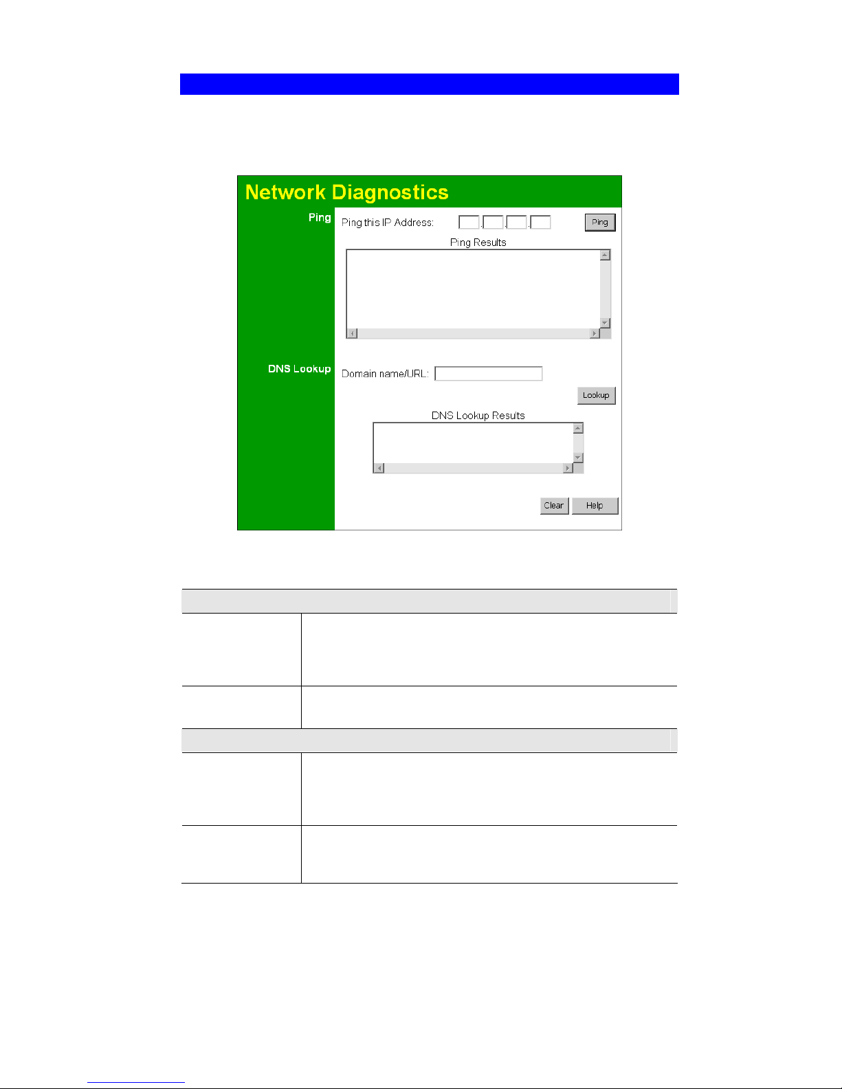
Wireless Router User Guide
76
Network Diagnostics
This screen allows you to perform a "Ping" or a "DNS lookup". These activities can be useful
in solving network problems.
An example Network Diagnostics screen is shown below.
Figure 46: Network Diagnostics Screen
Data - Network Diagnostics Screen
Ping
Ping this
IP Address
Enter the IP address you wish to ping. The IP address can be on your
LAN, or on the Internet. Note that if the address is on the Internet,
and no connection currently exists, you could get a "Timeout" error.
In that case, wait a few seconds and try again.
Ping Button
After entering the IP address, click this button to start the "Ping"
procedure. The results will be displayed in the Ping Results pane.
DNS Lookup
Domain
name/URL
Enter the Domain name or URL for which you want a DNS (Domain
Name Server) lookup. Note that if the address in on the Internet and
no connection currently exists, you could get a "Timeout" error. In
that case, wait a few seconds and try again.
Lookup Button
After entering the Domain name/URL, click this button to start the
"DNS Lookup" procedure. The results will be displayed in the DNS
Lookup Results pane.
Page 81
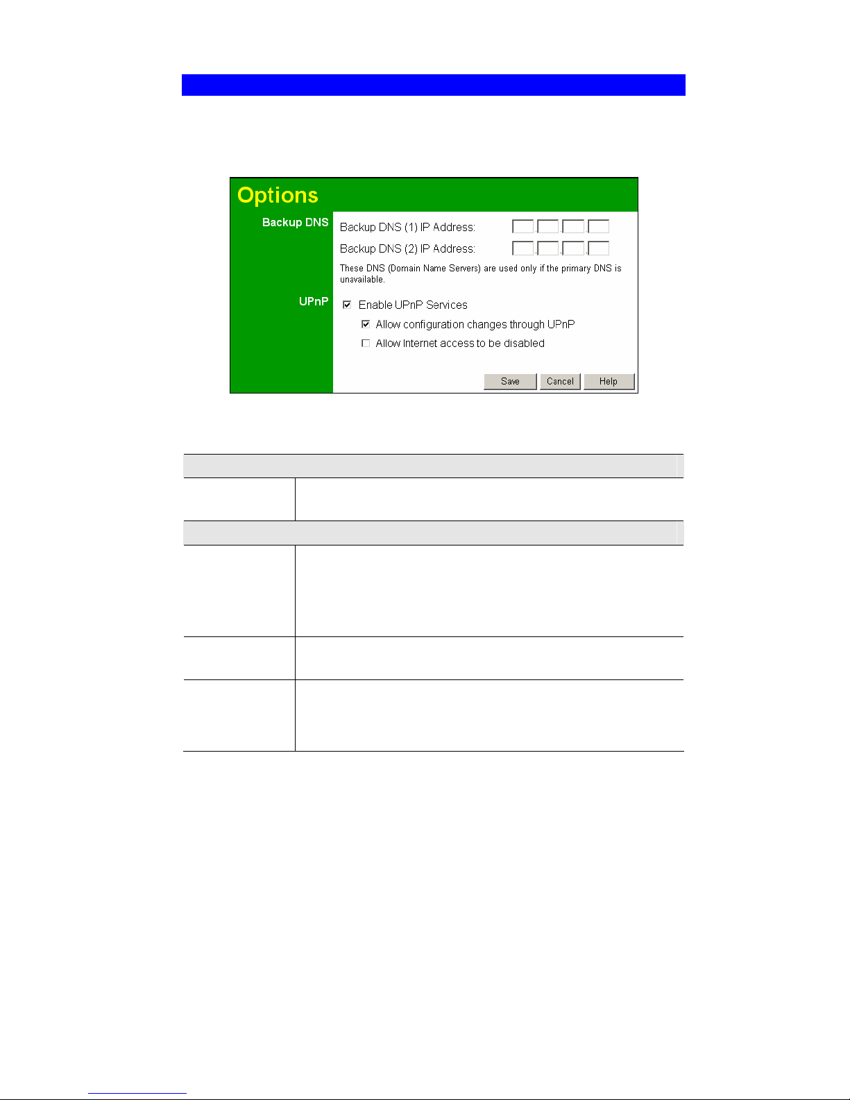
Advanced Administration
77
Options
This screen allows advanced users to enter or change a number of settings. For normal operation, there is no need to use this screen or change any settings.
An example Options screen is shown below.
Figure 47: Options Screen
Data - Options Screen
Backup DNS
IP Address
Enter the IP Address of the DNS (Domain Name Servers) here. These
DNS will be used only if the primary DNS is unavailable.
UpnP
Enable UPnP
Services
" UPnP (Universal Plug and Play) allows automatic discovery and
configuration of equipment attached to your LAN. UPnP is by
supported Windows ME, XP, or later.
" If Enabled, this device will be visible via UPnP.
" If Disabled, this device will not be visible via UPnP.
Allow Configuration...
" If checked, then UPnP users can change the configuration.
" If Disabled, UPnP users can only view the configuration.
Allow Internet
access to be
disabled
" If checked, then UPnP users can disable Internet access via this
device.
" If Disabled, UPnP users can NOT disable Internet access via this
device.
Page 82
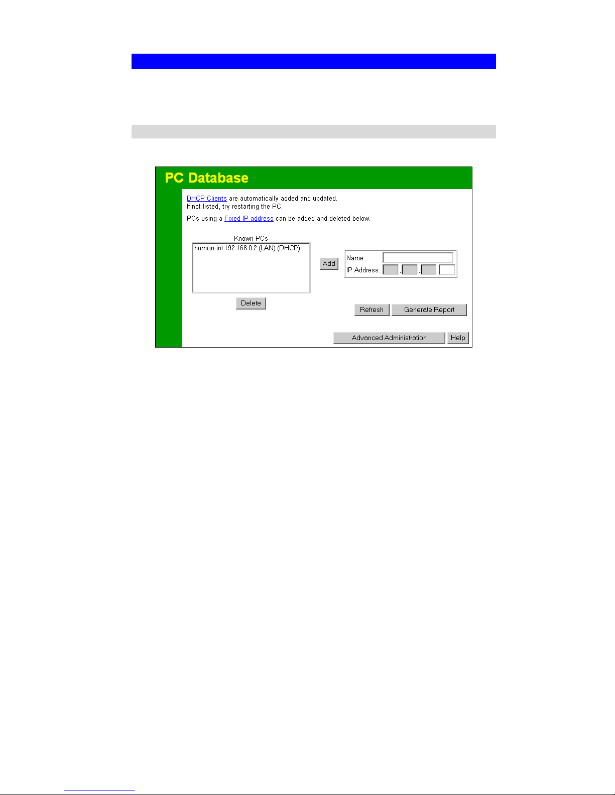
Wireless Router User Guide
78
PC Database
The PC Database is used whenever you need to select a PC (e.g. for the "DMZ" PC). It eliminates the need to enter IP addresses. Also, you do not need to use fixed IP addresses on your
LAN.
PC Database Screen
An example PC Database screen is shown below.
Figure 48: PC Database
" PCs which are "DHCP Clients" are automatically added to the database, and updated as
required.
" By default, non-Server versions of Windows act as "DHCP Clients"; this setting is called
"Obtain an IP Address automatically".
" The Wireless Router uses the "Hardware Address" to identify each PC, not the name or IP
address. The "Hardware Address" can only change if you change the PC's network card or
adapter.
" This system means you do NOT need to use Fixed (static) IP addresses on your LAN.
However, you can add PCs using Fixed (static) IP Addresses to the PC database if required.
Page 83

Advanced Administration
79
Data - PC Database Screen
Known PCs
This lists all current entries (PCs or network devices).
Name
If adding a new PC to the list, enter its name here. It is best if this
matches the PC's "hostname".
IP Address
If adding a new PC to the list, enter the IP Address of the PC here. The
PC will be sent a "ping" to determine its hardware address. If the PC is
not available (not connected, or not powered On) you will not be able
to add it.
Buttons
Add
This will add the new PC to the list. The PC will be sent a "ping" to
determine its hardware address. If the PC is not available (not connected, or not powered On) you will not be able to add it.
Delete
Delete the selected PC from the list. This should be done in 2 situations:
" The PC has been removed from your LAN.
" The entry is incorrect.
Refresh
Update the data on screen.
Generate Report
Display a read-only list showing full details of all entries in the PC
database.
Advanced
Administration
Click this to view the advanced "PC Database" screen.
Page 84

Wireless Router User Guide
80
PC Database (Admin)
This screen is displayed if the "Advanced Administration" button on the PC Database is
clicked. It provides more control than the standard PC Database screen.
Figure 49: PC Database (Admin)
Data - PC Database ( Admin) Screen
Known PCs
This lists all current entries. Data displayed is name (IP Address) type.
The "type" indicates whether the PC is connected to the LAN.
Edit
Use this to change the data for the selected PC in the list. The data for
the selected PC will then be shown in the "Properties" area, where it
may be edited. (Click "Update" to save any changes.)
Delete
Use this to Delete the selected PC from the list. This should be done in
2 situations:
" The PC has been removed from your LAN.
" The entry is incorrect.
PC Properties
Name
If adding a new PC to the list, enter its name here. It is best if this
matches the PC's "hostname".
Page 85

Advanced Administration
81
IP Address
Select the appropriate option:
" Automatic - The PC is set to be a DHCP client (Windows: "Ob-
tain an IP address automatically"). The Wireless Router will
allocate an IP address to this PC when requested to do so. The IP
address could change, but normally won't.
" DCHP Client - Reserved IP Address - Select this if the PC is set
to be a DCHP client, and you wish to guarantee that the Wireless
Router will always allocate the same IP Address to this PC.
Enter the required IP address. Only the last field is required; the
other fields must match the Wireless Router's IP address.
" Fixed IP Address - Select this if the PC is using a Fixed (Static)
IP address. Enter the IP address allocated to the PC. (The PC must
be configured to use this IP address.)
MAC Address
Select the appropriate option
" Automatic discovery - Select this to have the Wireless Router
contact the PC and find its MAC address. This is only possible if
the PC is connected to the LAN and powered On.
" MAC is - Enter the MAC address on the PC. The MAC address is
also called the "Hardware Address", "Physical Address", or "Network Adapter Address". The Broadband Router uses this to
provide a unique identifier for each PC. Because of this, the MAC
address can NOT be left blank.
Buttons
Add as New
Entry
Add a new PC to the list, using the data in the "Properties" box.
If "Automatic discovery" (for MAC address) is selected, the PC will be
sent a "ping" to determine its hardware address. This will fail unless the
PC is connected to the LAN, and powered on.
Update Selected
PC
Update (modify) the selected PC, using the data in the "Properties"
box.
Clear Form
Clear the "Properties" box, ready for entering data for a new PC.
Refresh
Update the data on screen.
Generate Report
Display a read-only list showing full details of all entries in the PC
database.
Standard Screen Click this to view the standard PC Database screen.
Page 86
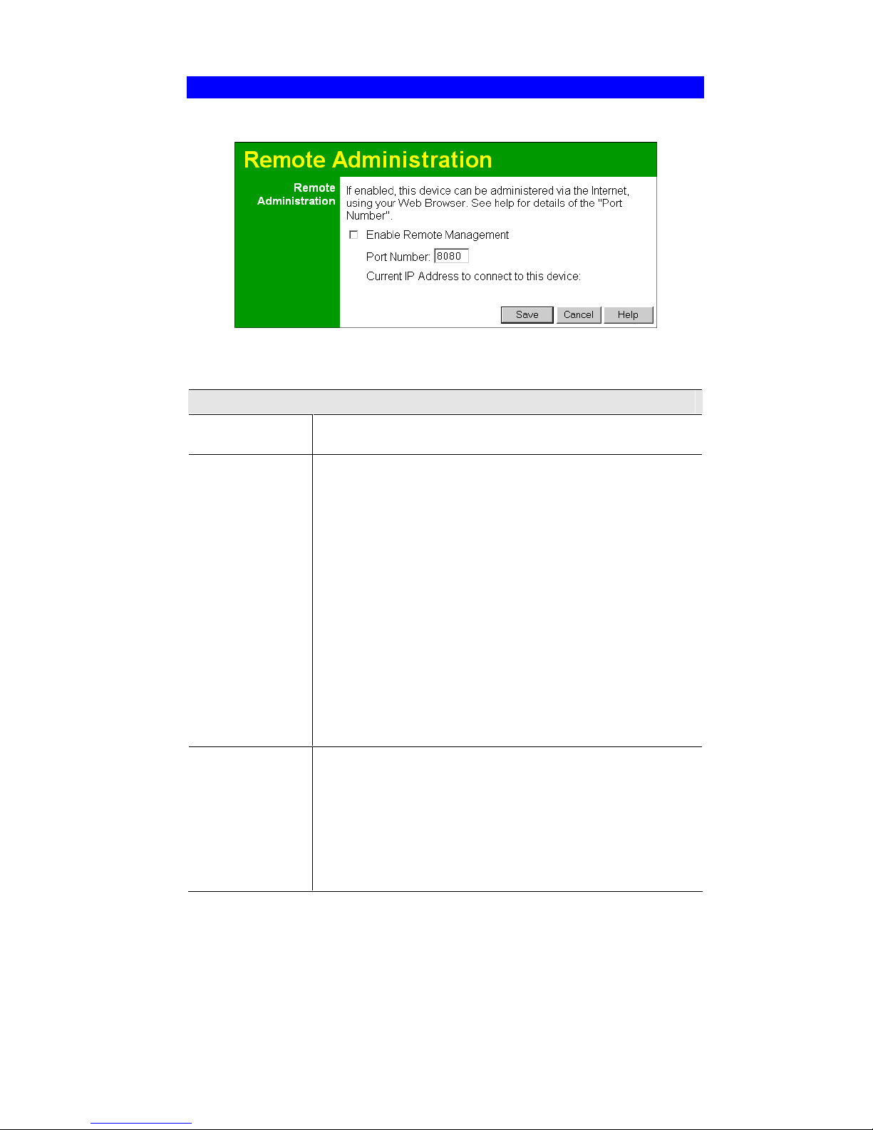
Wireless Router User Guide
82
Remote Administration
If enabled, this feature allows you to manage the Wireless Router via the Internet.
Figure 50: Remote Administration Screen
Data - Remote Administration Screen
Remote Administration
Enable Remote
Management
Enable to allow management via the Internet. If Disabled, this device
will ignore management connection attempts from the Internet.
Port Number
Enter a port number between 1024 and 65535. The default for HTTP
(Web) connections is port 80, but using port 80 will prevent the use
of a Web "Virtual Server" on your LAN. So using a different port
number is recommended. The default value is 8080.
The port number must be specified in your Browser when you connect. To specify the port number :
1. From a remote location, start your Browser.
2. In the "Address" or "Location" field, enter the Internet IP
address of this device (NOT the LAN IP address), followed by
the port number, as follows:
http://ip_address:port_number
Where:
i p_address is the Internet IP address of this device.
port _number is the port number assigned on this screen.
3. You should then be prompted for the password for this device.
(You must assign a password!)
Current IP
Address
To manage this device via the Internet, you need to know the IP
Address of this device, as seen from the Internet. This IP Address is
allocated by your ISP, and is shown here. But if using a Dynamic IP
Address, this value can change each time you connect to your ISP.
There are 2 solutions to this problem:
" Have your ISP allocate you a Fixed IP address.
" Use the DDNS feature (Advanced menu) so you can connect
using a Domain Name, rather than an IP address.
Page 87

Advanced Administration
83
To connect from a remote PC via the Internet
1. Ensure your Internet connection is established, and start your Web Browser.
2. In the "Address" bar, enter "HTTP://" followed by the Internet IP Address of the Wireless
Router. If the port number is not 80, the port number is also required. (After the IP Address,
enter ":" followed by the port number.)
e.g.
HTTP://123.123.123.123:8080
This example assumes the WAN IP Address is 123.123.123.123, and the port number is 8080.
Page 88

Wireless Router User Guide
84
Routing
Overview
" If you don't have other Routers or Gateways on your LAN, you can ignore the "Routing"
page completely.
" If the Wireless Router is only acting as a Gateway for the local LAN segment, ignore the
"Routing" page even if your LAN has other Routers.
" If your LAN has a standard Router (e.g. Cisco) on your LAN, and the Wireless Router is to
act as a Gateway for all LAN segments, enable RIP (Routing Information Protocol) and ig-
nore the Static Routing table.
" If your LAN has other Gateways and Routers, and you wish to control which LAN seg-
ments use each Gateway, do NOT enable RIP (Routing Information Protocol). Configure
the Static Routing table instead. (You also need to configure the other Routers.)
" If using Windows 2000 Data center Server as a software Router, enable RIP on the Broad-
band Router, and ensure the following Windows 2000 settings are correct:
" Open Routing and Remote Access
" In the console tree, select Routing and Remote Access , [server name], IP Routing,
RIP
" In the "Details" pane, right-click the interface you want to configure for RIP version 2,
and then click "Properties".
" On the "General" tab, set Outgoing packet protocol to "RIP version 2 broadcast", and
Incoming packet protocol to "RIP version 1 and 2".
Routing Screen
The routing table is accessed by the Routing link on the Administration menu.
Using this Screen
Generally, you will use either RIP (Routing Information Protocol) OR the Static Routing Table,
as explained above, although is it possible to use both methods simultaneously.
Static Routing Table
" If RIP is not used, an entry in the routing table is required for each LAN segment on your
Network, other than the segment to which this device is attached.
" The other Routers must also be configured. See Configuring Other Routers on your LAN
later in this chapter for further details and an example.
Page 89

Advanced Administration
85
Figure 51: Routing Screen
Data - Routing Screen
RIP
Enable RIP V1
Check this to enable the RIP (Routing Information Protocol) feature
of the Broadband Router
The Wireless Router supports RIP 1 only.
Static Routing
Static Routing
Table Entries
This list shows all entries in the Routing Table.
" The "Properties" area shows details of the selected item in the
list.
" Change any the properties as required, then click the "Update"
button to save the changes to the selected entry.
Properties
" Destination Network - The network address of the remote LAN
segment. For standard class "C" LANs, the network address are
the first 3 fields of the Destination IP Address. The 4th (last)
field can be left at 0.
" Network Mask - The Network Mask for the remote LAN seg-
ment. For class "C" networks, the default mask is 255.255.255.0
" Gateway IP Address - The IP Address of the Gateway or Router
which the Wireless Router must use to communicate with the
destination above. (NOT the router attached to the remote segment.)
" Metric - The number of "hops" (routers) to pass through to reach
the remote LAN segment. The shortest path will be used. The default value is 2.
Page 90

Wireless Router User Guide
86
Buttons
Save
Save the RIP setting. This has no effect on the Static Routing Table.
Add
Add a new entry to the Static Routing table, using the data shown in
the "Properties" area on screen. The entry selected in the list is
ignored, and has no effect.
Update
Update the current Static Routing Table entry, using the data shown
in the "Properties" area on screen.
Delete
Delete the current Static Routing Table entry.
Clear Form
Clear all data from the "Properties" area, ready for input of a new
entry for the Static Routing table.
Generate Report
Generate a read-only list of all entries in the Static Routing table.
Configuring Other Routers on your LAN
It is essential that all IP packets for devices not on the local LAN be passed to the Broadband
Router, so that they can be forwarded to the external LAN, WAN, or Internet. To achieve this,
the local LAN must be configured to use the Wireless Router as the Default Route or Default
Gateway.
Local Router
The local router is the Router installed on the same LAN segment as the Wireless Router. This
router requires that the Default Route is the Broadband Router itself. Typically, routers have a
special entry for the Default Route. It should be configured as follows.
Destination IP Address
Normally 0.0.0.0, but check your router documentation.
Network Mask
Normally 0.0.0.0, but check your router documentation.
Gateway IP Address
The IP Address of the Wireless Router.
Metric
2
Other Routers on the Local LAN
Other routers on the local LAN must use the Wireless Router’s Local Router as the Default
Route. The entries will be the same as the Wireless Router's local router, with the exception of
the Gateway IP Address.
" For a router with a direct connection to the Wireless Router's local Router, the Gateway IP
Address is the address of the Wireless Router's local router.
" For routers which must forward packets to another router before reaching the Wireless
Router's local router, the Gateway IP Address is the address of the intermediate router.
Page 91

Advanced Administration
87
Static Routing - Example
Figure 52: Routing Example
For the Broadband Router's Routing Table
For the LAN shown above, with 2 routers and 3 LAN segments, the Wireless Router requires 2
entries as follows.
Entry 1 (Segment 1)
Destination IP Address 192.168.1.0
Network Mask 255.255.255.0 (Standard Class C)
Gateway IP Address 192.168.0.100 (Broadband Router's local
Router)
Metric 2
Entry 2 (Segment 2)
Destination IP Address 192.168.2.0
Network Mask 255.255.255.0 (Standard Class C)
Gateway IP Address 192.168.0.100
Metric 3
For Router A's Default Route
Destination IP Address 0.0.0.0
Network Mask 0.0.0.0
Gateway IP Address 192.168.0.1 (Broadband Router's IP Address)
For Router B's Default Route
Destination IP Address 0.0.0.0
Network Mask 0.0.0.0
Gateway IP Address 192.168.1.80 (Broadband Router's local
router)
Page 92
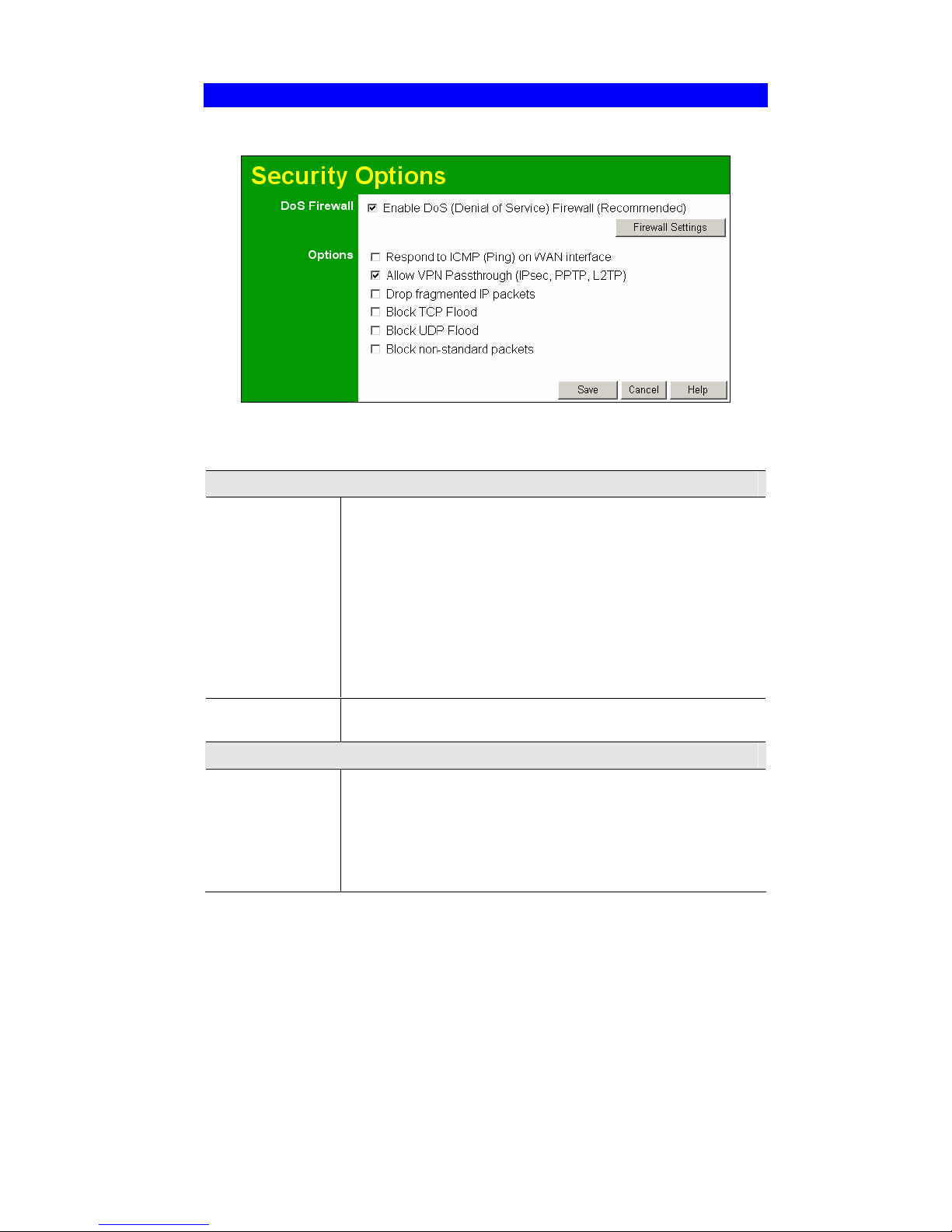
Wireless Router User Guide
88
Security
This screen allows you to set Firewall and other security-related options.
Figure 53: Security Screen
Data - Security Screen
DoS Firewall
Enable DoS
Firewall
If enabled, DoS (Denial of Service) attacks will be detected and
blocked. The default is enabled. It is strongly recommended that this
setting be left enabled.
Note:
" A DoS attack does not attempt to steal data or damage your PCs,
but overloads your Internet connection so you can not use it - the
service is unavailable.
" This device uses "Stateful Inspection" technology. This system
can detect situations where individual TCP/IP packets are valid,
but collectively they become a DoS attack.
Firewall Settings
Button
If you wish to adjust the settings used by the DoS firewall, click this
button to open a sub-window.
Options
Respond to ICMP
The ICMP protocol is used by the "ping" and "traceroute" programs,
and by network monitoring and diagnostic programs.
" If checked, the Wireless Router will respond to ICMP packets
received from the Internet.
" If not checked, ICMP packets from the Internet will be ignored.
Disabling this option provides a slight increase in security.
Page 93

Advanced Administration
89
Allow VPN
Pass through
The IPSec, PPTP, and L2TP protocols are used to establish a secure
connection, and are widely used by VPN (Virtual Private Networking) programs.
" If checked, these VPN connections are allowed.
" If not checked, these VPN connections are blocked.
Note: IPSec sessions must NOT use AH (Authentication Header).
Packets using AH cannot be routed correctly.
Drop fragmented
IP packets
If enabled, fragmented IP packets are discarded, forcing retransmission of these packets. In some situations, this could prevent
successful communication, so this setting is normally disabled.
Block TCP Flood
A TCP flood is excessively large number of TCP connection requests.
This is usually a DoS (Denial of Service) attack. This setting should
be normally being enabled.
Block UDP Flood
A UDP flood is excessively large number of UDP packets. This is
often a DoS (Denial of Service) attack, but some streaming applications also use UDP, and blocking UPD packets may prevent them
from working correctly.
Block
non-standard
packets
Abnormal packets are often used by hackers and in DoS attacks, but
may also be generated by other network devices. (PCs will normally
not generate non-standard packets.) This setting is disabled by default, but on most networks it can safely be enabled, and doing so will
provide greater protection.
Page 94
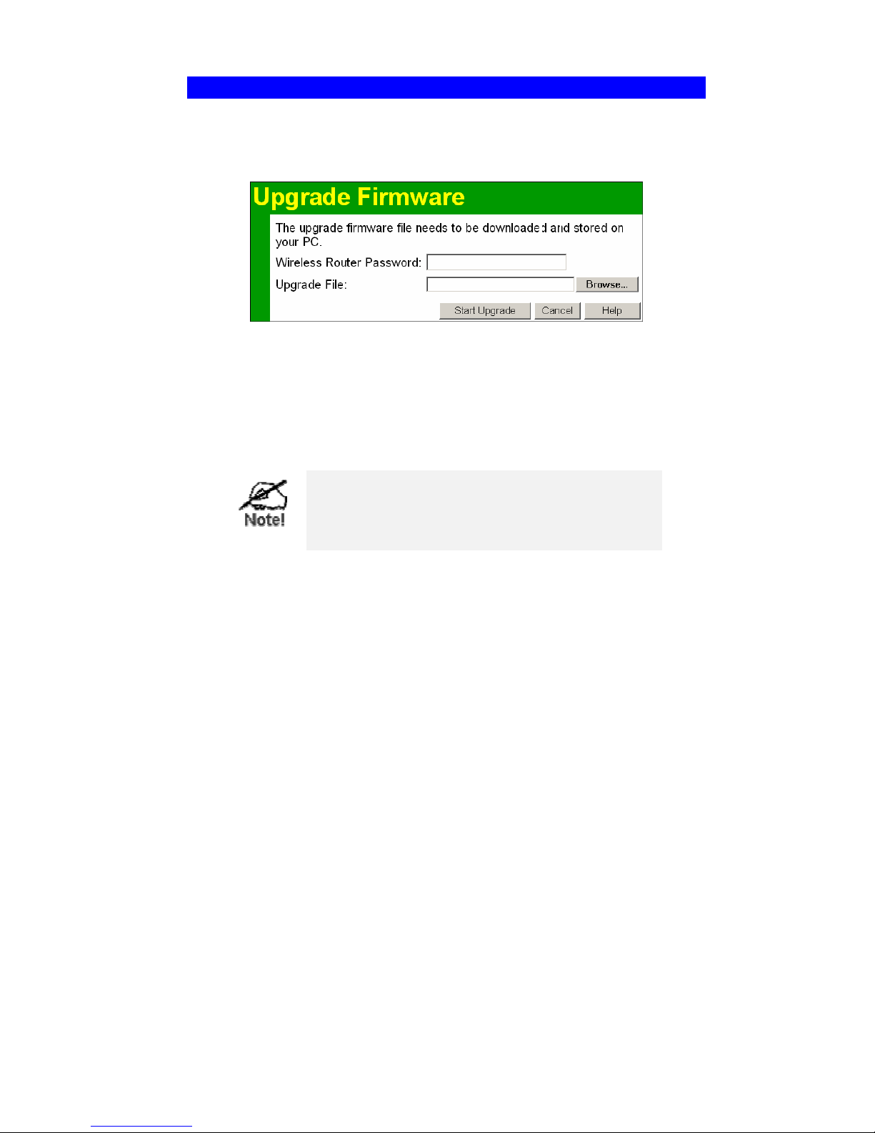
Wireless Router User Guide
90
Upgrade Firmware
The firmware (software) in the Wireless Router can be upgraded using your Web Browser.
You must first download the upgrade file, and then select Upgrade on the Administration menu.
You will see a screen like the following.
Figure 54: Upgrade Firmware Screen
To perform the Firmware Upgrade:
1. Click the "Browse" button and navigate to the location of the upgrade file.
2. Select the upgrade file. Its name will appear in the Upgrade File field.
3. Click the "Start Upgrade" button to commence the firmware upgrade.
The Wireless Router is unavailable during the upgrade process, and must restart when the upgrade is
completed. Any connections to or through the
Broadband Router will be lost.
Page 95

91
Appendix A
Troubleshooting
This Appendix covers the most likely problems and their solutions.
Overview
This chapter covers some common problems that may be encountered while using the Wireless
Router and some possible solutions to them. If you follow the suggested steps and the Wireless
Router still does not function properly, contact your dealer for further advice.
General Problems
Problem 1:
Can't connect to the Wireless Router to configure it.
Solution 1:
Check the following:
" The Wireless Router is properly installed, LAN connections are OK,
and it is powered ON.
" Ensure that your PC and the Wireless Router are on the same network
segment. (If you don't have a router, this must be the case.)
" If your PC is set to "Obtain an IP Address automatically" (DHCP
client), restart it.
" If your PC uses a Fixed (Static) IP address, ensure that it is using an IP
Address within the range 192.168.0.2 to 192.168.0.254 and thus compatible with the Wireless Router's default IP Address of 192.168.0.1.
Also, the Network Mask should be set to 255.255.255.0 to match the
Wireless Router.
In Windows, you can check these settings by using Control Panel-
Network to check the Properties for the TCP/IP protocol.
Internet Access
Problem 1: When I enter a URL or IP address I get a time out error.
Solution 1:
A number of things could be causing this. Try the following troubleshooting
steps.
" Check if other PCs work. If they do, ensure that your PCs IP settings are
correct. If using a Fixed (Static) IP Address, check the Network Mask,
Default gateway and DNS as well as the IP Address.
" If the PCs are configured correctly, but still not working, check the
Wireless Router. Ensure that it is connected and ON. Connect to it and
check its settings. (If you can't connect to it, check the LAN and power
connections.)
" If the Wireless Router is configured correctly, check your Internet
connection (DSL/Cable modem etc) to see that it is working correctly.
Problem 2:
Some applications do not run properly when using the Wireless Router.
A
Page 96

Wireless Router User Guide
92
Solution 2:
The Wireless Router processes the data passing through it, so it is not transparent.
Use the Special Applications feature to allow the use of Internet applications
which do not function correctly.
If this does solve the problem you can use the DMZ function. This should
work with almost every application, but:
" It is a security risk, since the firewall is disabled.
" Only one (1) PC can use this feature.
Page 97

93
Appendix B
About Wireless LANs
This Appendix provides some background information about using Wireless
LANs (WLANs).
Modes
Wireless LANs can work in either of two (2) modes:
" Ad-hoc
" Infrastructure
Ad-hoc Mode
Ad-hoc mode does not require an Access Point or a wired (Ethernet) LAN. Wireless Sta-
tions (e.g. notebook PCs with wireless cards) communicate directly with each other.
Infrastructure Mode
In Infrastructure Mode, one or more Access Points are used to connect Wireless Stations
(e.g. Notebook PCs with wireless cards) to a wired (Ethernet) LAN. The Wireless Stations
can then access all LAN resources.
Access Points can only function in "Infrastructure" mode,
and can communicate only with Wireless Stations which are
set to "Infrastructure" mode.
BSS/ESS
BSS
A group of Wireless Stations and a single Access Point, all using the same ID (SSID), form a
Basic Service Set (BSS).
Generally, using the same SSID is essential. Devices with different SSIDs are on different
Wireless LANs, and may be unable to communicate with each other.
Note that some Access Points will broadcast their SSID, allowing Wireless stations to adopt the
correct SSID. This makes it easier for the clients to locate the correct AP. If the SSID is not
broadcast, the client can still connect to the AP by entering the correct SSID and other data.
ESS
A group of Wireless Stations, and multiple Access Points, all using the same ID (ESSID), form
an Extended Service Set (ESS).
Different Access Points within an ESS can use different Channels. In fact, to reduce interference, it is recommended that adjacent Access Points SHOULD use different channels.
B
Page 98

Wireless Router User Guide
94
As Wireless Stations are physically moved through the area covered by an ESS, they will
automatically change to the Access Point which has the least interference or best performance.
This capability is called Roaming. (Access Points do not have or require Roaming capabilities.)
Channels
The Wireless Channel sets the radio frequency used for communication.
" Access Points use a fixed Channel. You can select the Channel used. This allows you to
choose a Channel which provides the least interference and best performance. In the USA
and Canada, 11 channels are available. If using multiple Access Points, it is better if adja-
cent Access Points use different Channels to reduce interference.
" In "Infrastructure" mode, Wireless Stations normally scan all Channels, looking for an
Access Point. If more than one Access Point can be used, the one with the strongest signal
is used. (This can only happen within an ESS.)
" If using "Ad-hoc" mode (no Access Point), all Wireless stations should be set to use the
same Channel. However, most Wireless stations will still scan all Channels to see if there is
an existing "Ad-hoc" group they can join.
WEP
WEP (Wired Equivalent Privacy) is a standard for encrypting data before it is transmitted.
This is desirable because it is impossible to prevent snoopers from receiving any data which is
transmitted by your Wireless Stations. But if the data is encrypted, then it is meaningless unless
the receiver can decrypt it.
If WEP is used, the Wireless Stations and the Access Point must have the same settings
for each of the following:
WEP
Off, 64 Bit, 128 Bit
Key
For 64 Bit encryption, the Key value must match.
For 128 Bit encryption, the Key value must match
WEP Authentication
Open System or Shared Key.
WPA
WPA (Wi-Fi Protected Access) is another standard for encrypting data before it is transmitted.
This is a later standard than WEP (Wired Equivalent Privacy), and provides greater security for
your data. Data is encrypted using a 256Bit key which is automatically generated and changed
often.
If all your Wireless stations support WPA, you should use this instead of WEP.
If WPA is used, the Wireless Stations and the Access Point must have the same settings
for each of the following:
WPA PSK
(Pre-shared Key)
Enter the same value on every station and the AP. The PSK
must be from 8 to 63 characters in length. The 256Bit key
used for the actual encryption is derived from this key.
Encryption
The same encryption method must be used. The most
Page 99

Appendix A - Troubleshooting
95
common encryption method is TKIP. Another widelysupported method is AES.
WPA2
WPA2 is another standard for encrypting data before it is transmitted. This is a later standard
than WPA (Wi-Fi Protected Access), and provides greater security for your data. Data is
encrypted using AES (Advanced Encryption Standard), a symmetric 128Bit block data
encryption technique, which is automatically generated and changed often.
If all your Wireless stations support WPA2, you should use this instead of WEP.
If WPA2 is used, the Wireless Stations and the Access Point must have the same settings
for each of the following:
WPA2
(Pre-shared Key)
Enter the same value on every station and the AP. The PSK
must be from 8 to 63 characters in length. The 256Bit key
used for the actual encryption is derived from this key.
Encryption
AES encryption method must be used.
WPA+WPA2
WPA+WPA2 is another standard for encrypting data before it is transmitted. If selected,
wireless clients may use either WPA or WPA2. This option is sometimes called "Mixed Mode".
Only one encryption method option is available – TKIP + AES, which is automatically generated and changed often. Clients may use either WPA (with TKIP) or WPA (with AES).
If all your Wireless stations support WPA+WPA2, you should use this instead of WEP.
If WPA+WPA2 is used, the Wireless Stations and the Access Point may use either WPA
(with TKIP) or WPA (with AES) for each of the following:
WPA+WPA2
(Pre-shared Key)
Enter the same value on every station and the AP. The PSK
must be from 8 to 63 characters in length. The 256Bit key
used for the actual encryption is derived from this key.
Encryption
Only one option is available – TKIP + AES. Clients may use
either WPA (with TKIP) or WPA (with AES).
Wireless LAN Configuration
To allow Wireless Stations to use the Access Point, the Wireless Stations and the Access Point
must use the same settings, as follows:
Mode
On client Wireless Stations, the mode must be set to "Infrastructure".
(The Access Point is always in "Infrastructure" mode.)
Most Wireless stations will set the correct mode automatically.
SSID (ESSID)
Wireless Stations should use the same SSID (ESSID) as the Access Point
they wish to connect to. Alternatively, the SSID can be set to "any" or
null (blank) to allow connection to any Access Point.
Page 100

Wireless Router User Guide
96
Security
The Wireless Stations and the Access Point must use the same settings
for Wireless security. (Off, WEP, WPA, WPA2, WPA+WPA2).
WEP: If WEP is used, the Key size (64Bit, 128Bit), Key value, and
Authentication settings must be the same on the Wireless Stations and the
Access Point.
WPA: If WPA is used, all Wireless Stations must be set to use WPA,
and have the same Pre-shared Key and encryption system.
WPA2: If WPA2 is used, all Wireless Stations must be set to use
WPA2, and have the same Pre-shared Key and encryption system.
WPA+WPA2: If WPA+WPA2 is used, all Wireless Stations may use
either WPA (with TKIP) or WPA (with AES).
For Ad-hoc networks (no Access Point), all Wireless stations must use
the same security settings.
 Loading...