

Page 1

Wireless LAN Switch
WLS-1280
User’s Manual
Version 1.00
Page 2

Copyright
Copyright © 2006 by PLANET Technology Corp. All rights reserved. No part of this publication may be reproduced,
transmitted, transcribed, stored in a retrieval system, or translated into any language or computer language, in any form or b y
any means, electronic, mechanical, magnetic, optical, chemical, manual or other wise, without the prior written permission of
PLANET.
PLANET makes no representations or warranties, either expressed or implied, with respect to the contents hereof and
specifically disclaims any warranties, merchantability or fitness for any particular purpose. Any software described in this
manual is sold or licensed "as is". Should the programs prove defective following their purchase, the buyer (and not PLANET,
its distributor, or its dealer) assumes the entire cost of all necessary servicing, repair, and any incidental or consequential
damages resulting from any defect in the software. Further, PLANET reserves the right to revise this publication and to make
changes from time to time in the contents hereof without obligation to notify any person of such revision or changes.
All brand and product names mentioned in this manual are trademarks and/or registered trademarks of their
respective holders.
Federal Communication Commission Interference Statement
This equipment has been tested and found to comply with the limits for a Class B digital device, pursuant to Part 15 of FCC
Rules. These limits are designed to provide reasonable protection against harmful interference in a residential installation. This
equipment generates, uses, and can radiate radio frequency en ergy and, if not installed and used in accordance with the
instructions, may cause harmful interference to radio communications. However, there is no guarantee that interference w ill no t
occur in a particular installation. If this equipment does cause harmful interference to radio or television reception, which can be
determined by turning the equipment off and on, the user is encouraged to try to correct the interference by one or more of the
following measures:
1. Reorient or relocate the receiving antenna.
2. Increase the separation between the equipment and receiver.
3. Connect the equipment into an outlet on a circuit different from that to which the receiver is connected.
4. Consult the dealer or an experienced radio technician for help.
FCC Caution
To assure continued compliance. (example-use only shielded interface cables when connecting to computer or peripheral
devices). Any changes or modifications not expressly approved by the party responsible for compliance could void the user ’s
authority to operate the equipment.
This device complies with Part 15 of the FCC Rules. Operation is subject to the Following two conditions: ( 1 ) This device may
not cause harmful interference, and ( 2 ) this Device must accept any interference received, including interference that may
cause undesired operation.
Federal Communication Commission (FCC) Radiation Exposure Statement
This equipment complies with FCC radiation exposure set forth for an uncontrolled environment. In order to avoid the
possibility of exceeding the FCC radio frequency exposure limits, human proximity to the antenna shall not be less than 20 cm
2
Page 3

(8 inches) during normal operation.
Safety
This equipment is designed with the utmost care for the safety of those who install and use it. Ho wever, special attention must
be paid to the dangers of electric shock and static electricity when working with electrical equipment. All guidelines of this and
of the computer manufacture must therefore be allowed at all times to ensure the safe use of the equipment.
EU Countries Not Intended for Use
The ETSI version of this device is intended for home and office use in Austria Belgium, Denmark, Finland, France (with
Frequency channel restrictions). Germany, Greece, Ireland, Italy, Luxembourg .The Netherlands, Portugal, Spain, Sweden and
United Kingdom.
The ETSI version of this device is also authorized for use in EFTA member states Iceland, Liechtenstein, Norway and
Switzerland.
WEEE regulation
To avoid the potential effects on the environment and human health as a result of the presence of
hazardous substances in electrical and electronic equipment, end users of electrical and electronic
equipment should understand the meaning of the crossed-out wheeled bin symbol. Do not dispose of
WEEE as unsorted municipal waste and have to collect such WEEE separately.
Revision
User’s Manual for PLANET Wireless LAN Switch
Model: WLS-1280
Rev: 1.0 (Oct, 2006)
Part No. EM-WLS1280
3
Page 4

Table of Contents
1. Before You Start ............................................................................................................................3
1.1 Preface ....................................................................................................................................................3
1.2 Document Convention............................................................................................................................3
2. System Overview ...........................................................................................................................3
2.1 Introduction of PLANET WLS-1280......................................................................................................3
2.2 System Concept ......................................................................................................................................4
2.3 Specification ...........................................................................................................................................5
2.3.1 Hardware Specification.................................................................................................................................5
2.3.2 Technical Specification.................................................................................................................................5
3. Base Installation...........................................................................................................................8
3.1 Hardware Installation..............................................................................................................................8
3.1.1 System Requirements....................................................................................................................................8
3.1.2 Package Contents..........................................................................................................................................8
3.1.3 Panel Function Descriptions .........................................................................................................................9
3.1.4 Installation Steps.........................................................................................................................................10
3.2 Software Configuration.........................................................................................................................12
3.2.1 Quick Configuration ...................................................................................................................................12
3.2.2 User Login Portal Page...............................................................................................................................22
4. Web Interface Configuration......................................................................................................24
4.1 System Configuration ...........................................................................................................................26
4.1.1 Configuration Wizard..................................................................................................................................26
4.1.2 System Information.....................................................................................................................................27
4.1.3 WAN1 Configuration..................................................................................................................................29
4.1.4 WAN2 & Failover.......................................................................................................................................31
4.1.5 LAN Port Roles...........................................................................................................................................33
4.1.6 Controlled Configuration............................................................................................................................34
4.1.7 Uncontrolled Configuration........................................................................................................................36
4.2 User Authentication ..............................................................................................................................40
4.2.1 Authentication Configuration .....................................................................................................................40
4.2.2 Black List Configuration.............................................................................................................................57
4.2.3 Policy Configuration...................................................................................................................................60
4.2.4 Additional Configuration............................................................................................................................64
4.3 AP Management....................................................................................................................................82
4.3.1 AP List........................................................................................................................................................82
4.3.2 AP Discovery..............................................................................................................................................94
4.3.3 Manual Configuration.................................................................................................................................95
i
Page 5

4.3.4 Template Settings........................................................................................................................................95
4.3.5 Firmware Management...............................................................................................................................96
4.3.6 AP Upgrade.................................................................................................................................................96
4.4 Network Configuration.........................................................................................................................96
4.4.1 Network Address Translation......................................................................................................................97
4.4.2 Privilege List.............................................................................................................................................100
4.4.3 Monitor IP List..........................................................................................................................................101
4.4.4 Walled Garden List ...................................................................................................................................102
4.4.5 Proxy Server Properties ............................................................................................................................103
4.4.6 Dynamic DNS...........................................................................................................................................105
4.4.7 IP Mobility................................................................................................................................................105
4.4.8 VPN T erm ination......................................................................................................................................105
4.5 Utilities................................................................................................................................................107
4.5.1 Change Password......................................................................................................................................107
4.5.2 Backup/Restore Settings...........................................................................................................................109
4.5.3 Firmware Upgrade....................................................................................................................................109
4.5.4 Restart.......................................................................................................................................................110
4.6 Status...................................................................................................................................................111
4.6.1 System Status............................................................................................................................................112
4.6.2 Interface Status..........................................................................................................................................113
4.6.3 Current Users............................................................................................................................................115
4.6.4 Traffic History...........................................................................................................................................116
4.6.5 Notification Configuration........................................................................................................................117
4.7 Help.....................................................................................................................................................119
5. Appendix A – Console Interface...............................................................................................120
6. Appendix B – Network Configuration on PC..........................................................................123
7. Appendix C – IPSec VPN.........................................................................................................128
8. Appendix D –Proxy Setting for Hotspot...................................................................................133
9. Appendix E –Proxy Setting for Enterprise ..............................................................................136
10. Appendix F –Disclaimer for Users...........................................................................................141
ii
Page 6
1. Before You Start
1.1 Preface
This manual is for Hotspot owners or administrators in enterprises to set up network environment using PLANET
WLS-1280. It contains step by step procedures and graphic examples to guide MIS staff or individuals with slight
network system knowledge to complete the installation.
1.2 Document Convention
y For any caution or warning that requires special attention of readers, a highlight box with the eye-catchi ng ital ic
font is used as below:
Warning: For security purposes, you should immediately change the Administrator’s password.
Indicates that clicking this button will return to the homepage of this section.
Indicates that clicking this button will return to the previous page..
Indicates that clicking this button will apply all of your settings.
Indicates that clicking this button will clear what you set before these settings are applied.
2. System Overview
2.1 Introduction of PLANET WLS-1280
PLANET WLS-1280 is an all-in-one product specially designed for Hotspot wireless network environment. It
integrates “Access Control” and “Wireless Network Access” into one system to fulfill the needs in Hotspot
environment.
3
Page 7
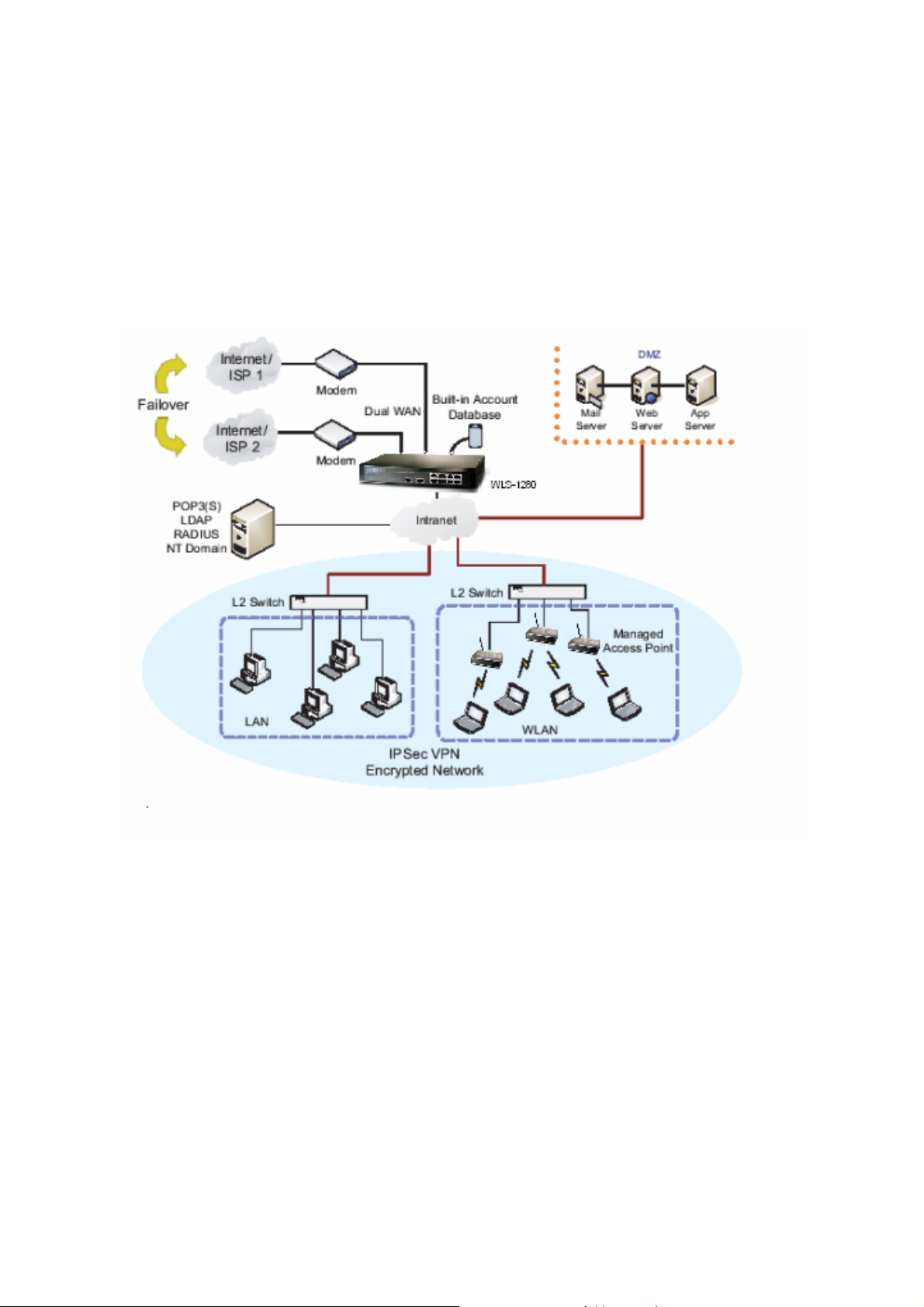
2.2 System Concept
PLANET WLS-1280 is specially designed for user aut hentication, a uthorization and man age m ent. The u ser account
information is stored in the local database or a specified external dat abases server. User authentication is processed
via the SSL encrypted web interface. This interface is com patible to most desktop device s and p alm computers. The
following figure is an example of PLANET WLS-1280 set to control a part of the company’s intranet. The whole
managed network includes the cable network users and the wireless network users.
4
Page 8

2.3 Specification
2.3.1 Hardware Specification
y General
Form Factor: Mini-desktop
Dimensions (W x D x H): 243 mm x 150 mm x 45.5 mm
Weight: 1.4 Kg
Operating Temperature: 0 ~ 45 oC
Storage Temperature: 0 ~ 65 oC
Power: 110~220 VAC, 50/60 Hz
Ethernet Interfaces: 10 x Fast Ethernet (10/100 Mbps)
y Connectors & Display
WAN Ports: 2 x 10BASE-T/100BASE-TX RJ-45
LAN Ports: 8 x 10BASE-T/100BASE-TX RJ-45
Console Port: 1 x RJ-11
LED Indicators: 1 x Power, 1 x Status, 2 x WAN, 8 x LAN
2.3.2 Technical Specification
y Networking
Supports Router, NAT mode
Supports Static IP, DHCP, PPPoE on WAN interface
Configurable LAN ports authentication
Supports IP Plug and Play (IP PnP)
Built-in DHCP server and supports DHCP relay
Supports NAT:
1. IP/Port Destination Redirection
2. DMZ Server Mapping
3. Virtual Server Mapping
Supports static route
Supports SMTP redirection
Supports Wal l ed Garden (free surfing zone)
Supports MAC Address Pass-Through
Supports HTTP Proxy
y Security
Supports data encryption: WEP (64/1 28 -bit), WPA, WPA2
Supports authentication: WPA-PSK, WPA2-PSK, IEEE 802.1x (EAP-MD5, EAP-TLS, CHAP, PEAP)
Supports VPN Pass-through (IPSec and PPTP)
5
Page 9

Supports DoS attack protection
Supports user Black List
Allows user identity plus MAC address authentication for local accounts
y User Management
Supports up to 120 concurrent users
Provides 500 local accounts
Provides 2000 on-demand accounts
Simultaneous support for multiple authentication methods (Local and On-demand accounts, POP3(S),
LDAP, RADIUS, NT Domain)
Role-based and policy-based access control (per-role assignments based on Firewall policies, Routing,
Login Schedule, Bandwidth)
Customizable login and logout portal page
User Session Management:
1. SSL protected login portal page
2. Supports multiple logins with one single account
3. Session idle timer
4. Session/account expiration control
5. Friendly notification email to provide a hyperlink to login portal page
6. Windows domain transparent login
7. Configurable login time frame
y AP Management
Supports up to 12 manageable IEEE 802.11 compliant APs
Centralized remote management via HTTP/SNMP interface
Automatic discovery of managed APs and list of managed APs
Allows administrators to add and delete APs from the device list
Allows administrators to enable or disable managed APs
Provides MAC Access Control List of client stations for each managed AP
Locally maintained configuration profiles of managed APs
Single UI for upgrading and restoring managed APs’ firmware
System status monitoring of managed APs and associated client stations
Automatic recovery of APs in case of system failure
System alarms and status reports on managed APs
y Monitoring and Reporting
Status monitoring of on-line users
IP-based monitoring of network devices
WAN connection failure alert
Syslog support for diagnosing and troubleshooting
User traffic history logging
y Accounting and Billing
6
Page 10

Support for RADIUS accounting, RADIUS VSA (Vendor Specific Attribute s)
Built-in billing profiles for on-demand accounts
Enables session expiration control for on-demand accounts by time (hour) and data volume (MB)
Provides billing report on screen for on-demand accounts
Detailed per-user traffic history based on time and data volume for both local and on-demand accounts
Traffic history report in an automatic email to administrator
y System Administration
Multi-lingual, web-based management UI
SSH remote management
Remote firmware upgrade
NTP time synchronization
Backup and restore of system configuration
7
Page 11

3. Base Installation
3.1 Hardware Installation
3.1.1 System Requirements
y Standa rd 10/100BaseT including five network cables with RJ-45 connectors
y All PCs need to install the TCP/IP network proto col
3.1.2 Package Contents
The standard package of PLANET WLS-1280 in cludes:
y PLANET WLS-1280 x 1
y CD-ROM x 1
y Quick Installation Guide x 1
y Power Adapter (DC 12V) x 1
y Cross Over Ethernet Cable x 1
y Console Cable x 1
Warning: It is highly recommended to use all the supplies in the package inste ad of sub stituting any com ponents by
other suppliers to guarantee best performance.
8
Page 12
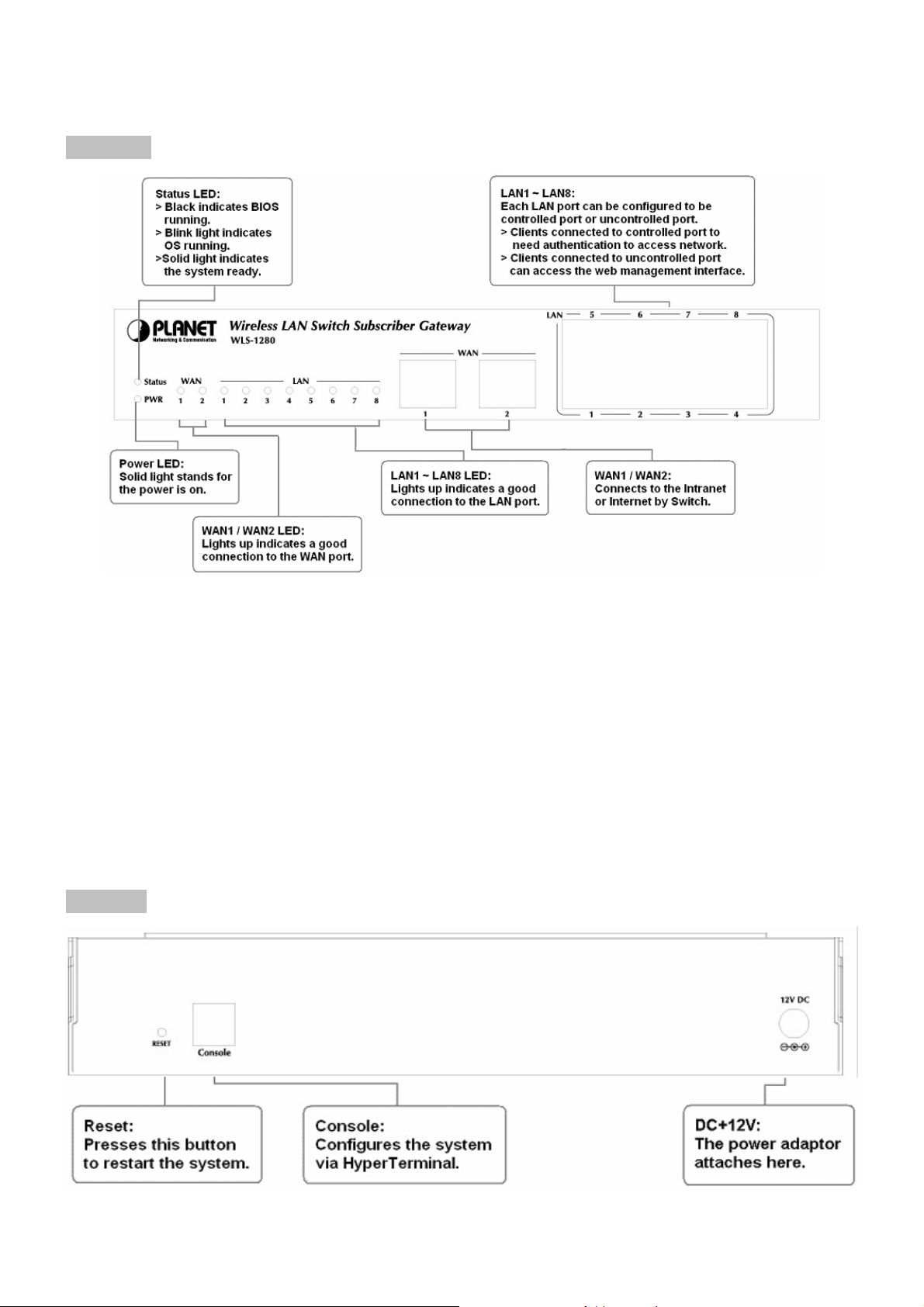
3.1.3 Panel Function Descriptions
Front Panel
y LED: There are four kinds of LED, PWR, Status, WAN and LAN LED, to indicate different status of the system.
y WAN1/WAN2: The two WAN ports are connected to a network which is not managed by PLANET WLS-1280
system, and this port can be used to connect the ATU-Router of ADSL, the port of Cable Modem, or the Switch
or Hub on the LAN of a company. WAN2 doesn’t support load balance with WAN1
y LAN1~LAN8: Client machines connect to PLANET WLS-1280 via LAN ports. Each LAN port can be configured
to one of two roles, controlled or uncontrolled. The differences of these two roles for a client connected to are:
¾ Clients connected to controlled port to need authentication to access network.
¾ Clients connected to uncontrolled port can access the web management interfa c e.
Rear Panel
9
Page 13
y Reset: Press this button to restart the system.
y Console: The system can be configured via serial console port. An administrator can use terminal emulation
program such as Microsoft’s HyperTerminal to login to the configuration console interface to change admin
password or monitor syste m status, etc.
y DC+12V: The power adapter attaches here.
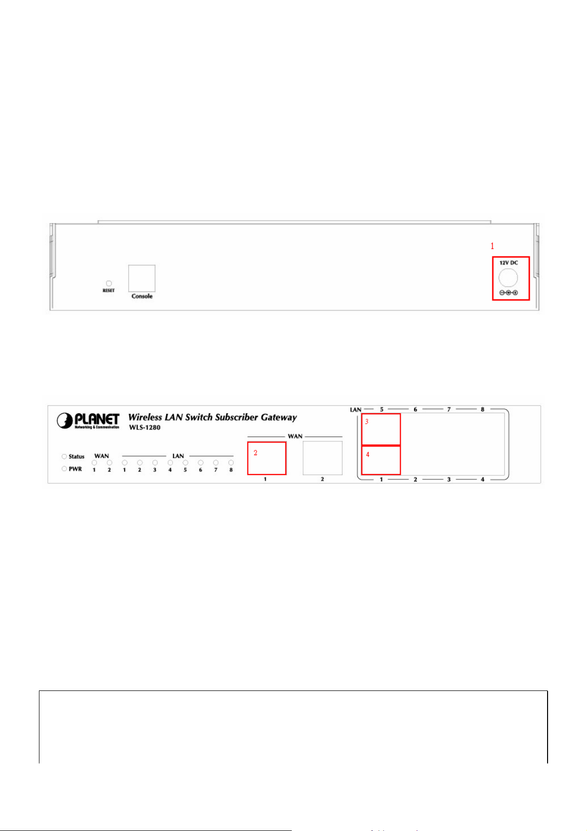
3.1.4 Installation Steps
Please follow the following steps to install PLANET WLS-1280:
1. Connect the 12V DC power adapter to the power connector socket on the rear panel. The Power LED should be
on to indicate a proper connection.
2. Connect an Ethernet cable to the WAN1 Port on the front panel. Connect the other end of the Ethernet cable to
ADSL modem, cable modem or a switch/hub of the internal network. The LED of WAN1 port should be on to
indicate a proper connection.
3. Connect an Ethernet cable to one of the LAN5~LAN8 Port on the front panel. Connect the other end of the
Ethernet cable to a client’s PC. The LED of the connected port should be on to indicate a pro per connection.
(Note: The default role of these four ports is Uncontrolled Port.)
4. Connect an Ethernet cable to one of the LAN1~LAN4 Port on the front panel. Connect the other end of the
Ethernet cable to a client PC, AP or switch in manag e d network. The LED of the connected port should be o n to
indicate a proper connection. (Note: The default role of these four ports is Controlled Port.)
Attention:
1. PLANET WLS-1280 supports Auto Sensing MDI/MDIX. You may use either straight through or cross over cable
to connect the Ethernet Port.
2. Usually a straight cable could be applied when PLANE T WLS -1280 connect s to a n Access Point which supports
10
Page 14

automatic crossover. If af ter the AP hardware resets, PLANET WL S-1280 could not be able to co nnect to t he AP
while connecting with a straight cable, the user have to pull out and plug-in the straight cable again. This
scenario does NOT occur while using a cros sover cable.
After the hardware of PLANET WLS-1280 is installed completely, t he system is ready to be configured in the
following sections.
11
Page 15
3.2 Software Configuration
3.2.1 Quick Configuration
There are two ways to configure the system: using Configuration Wizard or change the setting by demands
manually. The Configuration Wizard has 6 steps providing a simple and easy way to guide you through the setup of
PLANET WLS-1280. Follow the procedures and instructions given by the Wizard to enter the required information
step by step. After saving and re sta rting PLANET WLS-128 0, it is ready to use. There will be 6 steps as listed belo w:
1. Change Admin’s Password
2. Choose System’s Time Zone
3. Set System Information
4. Select the Connection Type for WAN Port
5. Set Authentication Methods
6. Save and Restart PLANET WLS-1280
Please follow the following steps to complete the quick configuration.
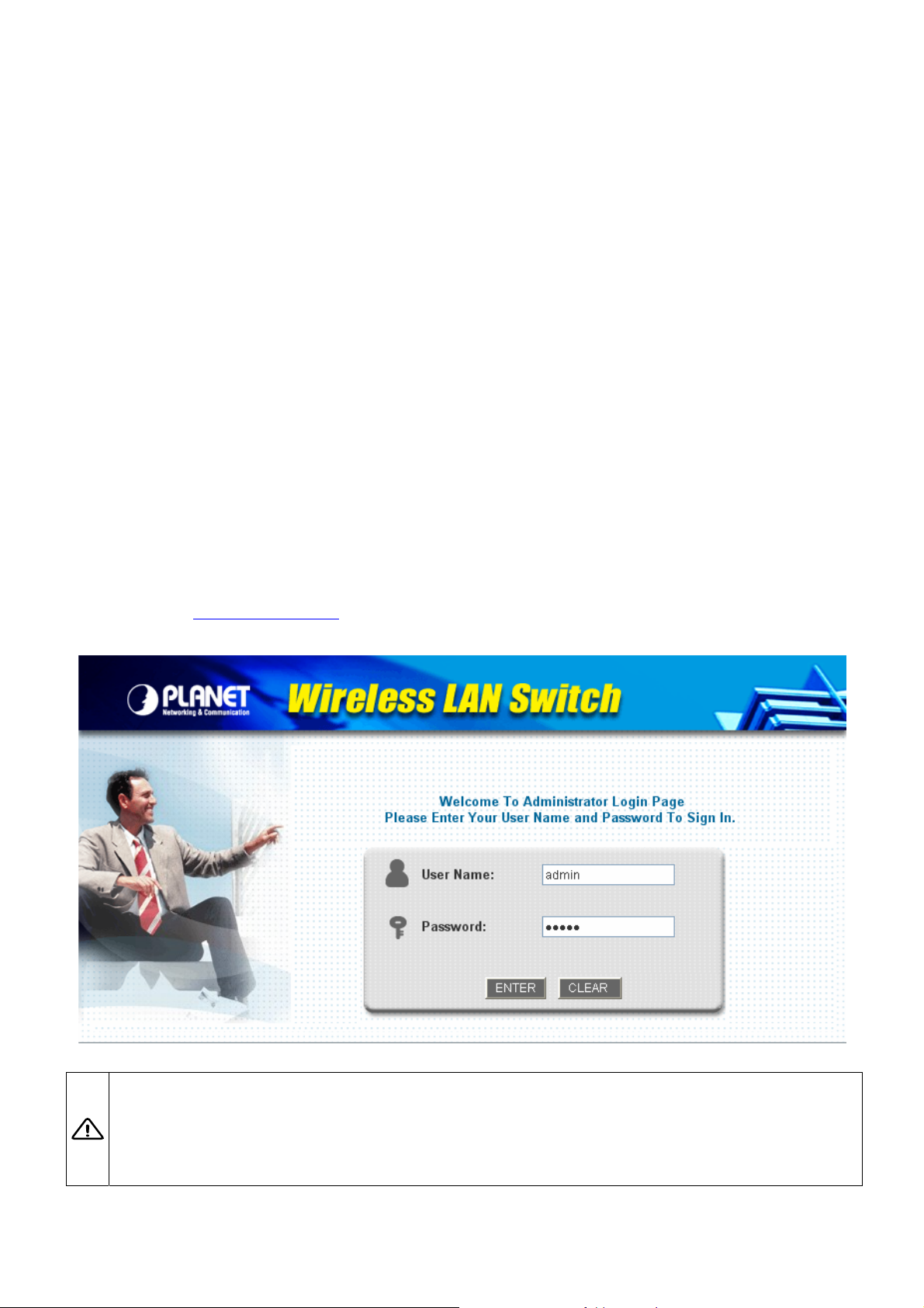
1. Use the network cable of the 10/100BaseT to connect a PC to the uncontrolled port, and then start a browser
(such as Microsoft IE or Firefox). Next, enter the gateway IP address as the web management interfa ce’s URL,
the default is
default username and password, in the User Name and Password column. Click Enter to log in.
https://192.168.2.254. In the opened webpage, you will see the login screen. Enter “admin”, the
Caution :If you can’t get the login screen, the reasons may be: 1. The PC is set incorrectly so that the PC can’t obtain the
IP address automatically from the LAN port; 2. The IP address and the default gateway are not under the same network
segment. Please use default IP address such as 192.168.2.xx in your network and then try it again. For the PC
configuration on PC, please refer to 6. Appendix B – Network Configuration on PC.
12
Page 16

PLANET WLS-1280 supports three kinds of account interface. You can log in as admin, manager or operator. The
default username and password as follows.
Admin: The administrator can access all area of PLANET WLS-1280.
User Name: admin
Password: admin
Manager: The manager can access the area under User Authentication to manage the user account, but no
permission to change the settings of the profiles of Firewall, Specific Route and Schedule.
User Name: manager
Password: manager
Operator: The operator can only access the area of Create On-demand User to create and print out the new
on-demand user accounts.
User Name: operator
Password: operator
2. After successfully logging into PLANET WLS-1280, enter the web management interface and see the welcome
screen. There is a Logout button on the upper right corner to log out the system when finished.
3. Then, run the configuration wizard to complete the configuration. Click System Configuration to the System
Configuration homepage.
13
Page 17
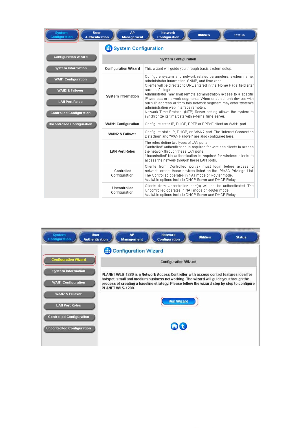
4. Click the System Configuration from the top menu and the homepage of System Configuration will appear.
Then, click on Configuration Wizard and click the Run Wizard button to start the wizard.
14
Page 18
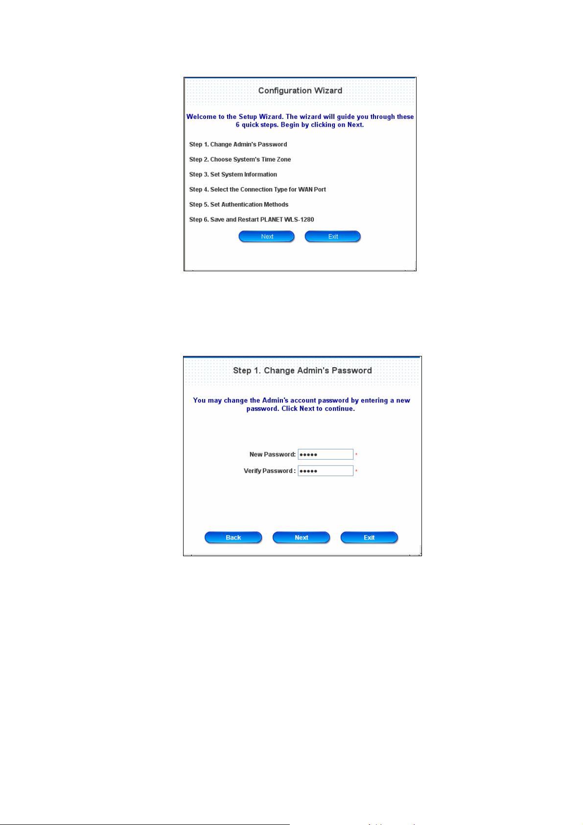
5. Configuration Wizard
A welcome screen that briefly introduces the 6 steps will appear. Click Next to begin.
y Step 1. Change Admin’s Password
Enter a new password for the admin account and retype it in the verify password field (twenty-character
maximum and no spaces).
Click Next to continue.
15
Page 19
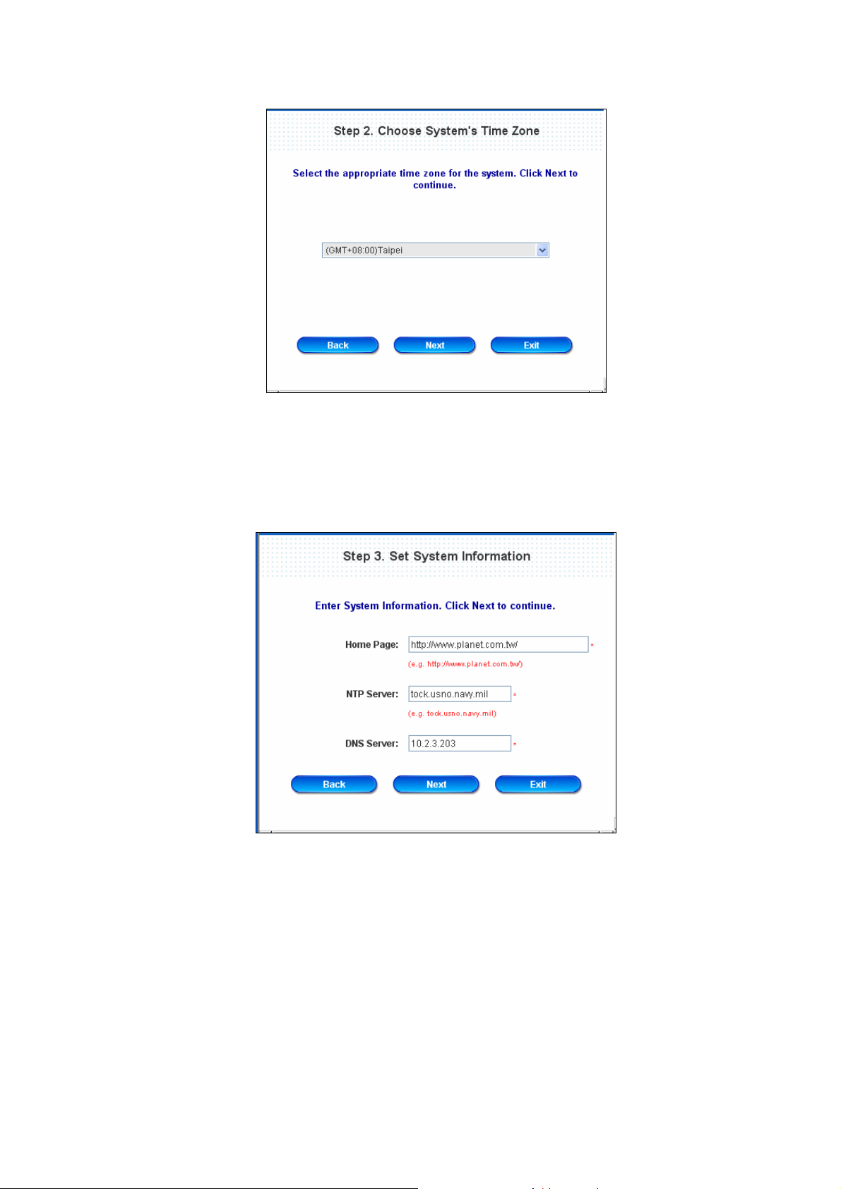
y Step 2. Choose System’s Time Zone
Select a proper time zone via the drop-down menu.
Click Next to continue.
y Step 3. Set System Information
Home Page: Enter the URL to where the users should be directed when they are successfully
authenticated.
NTP Server: Enter the IP address or do main name of external time server for PLANET WLS-1280 time
synchronization or use the default.
DNS Server: Enter a DNS Server provided by the ISP (Internet Service Provider). Contact the ISP if the
DNS IP Address is unknown.
Click Next to continue.
16
Page 20
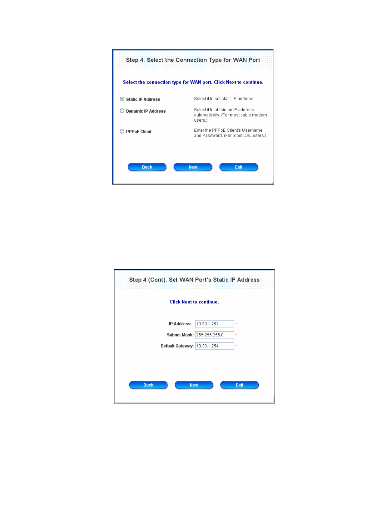
y Step 4. Select the Connection Type for WAN Port
Three are three types of WAN1 port to select in wizard: Static IP Address, Dynamic IP Address and
PPPoE Client.
Select a proper Internet connection type and click Next to continue.
¾ Static IP Address: Set WAN Port’s Static IP Address
Enter the “IP Address”, “Subnet Mask” and “Default Gateway” provided by your ISP or network
administrator.
Click Next to continue.
¾ Dynamic IP Address
If this option is selected, PLANET WLS-1280 will obtain IP settings from external DHCP server on
network connected by WAN1 automatically.
Click Next to continue.
17
Page 21
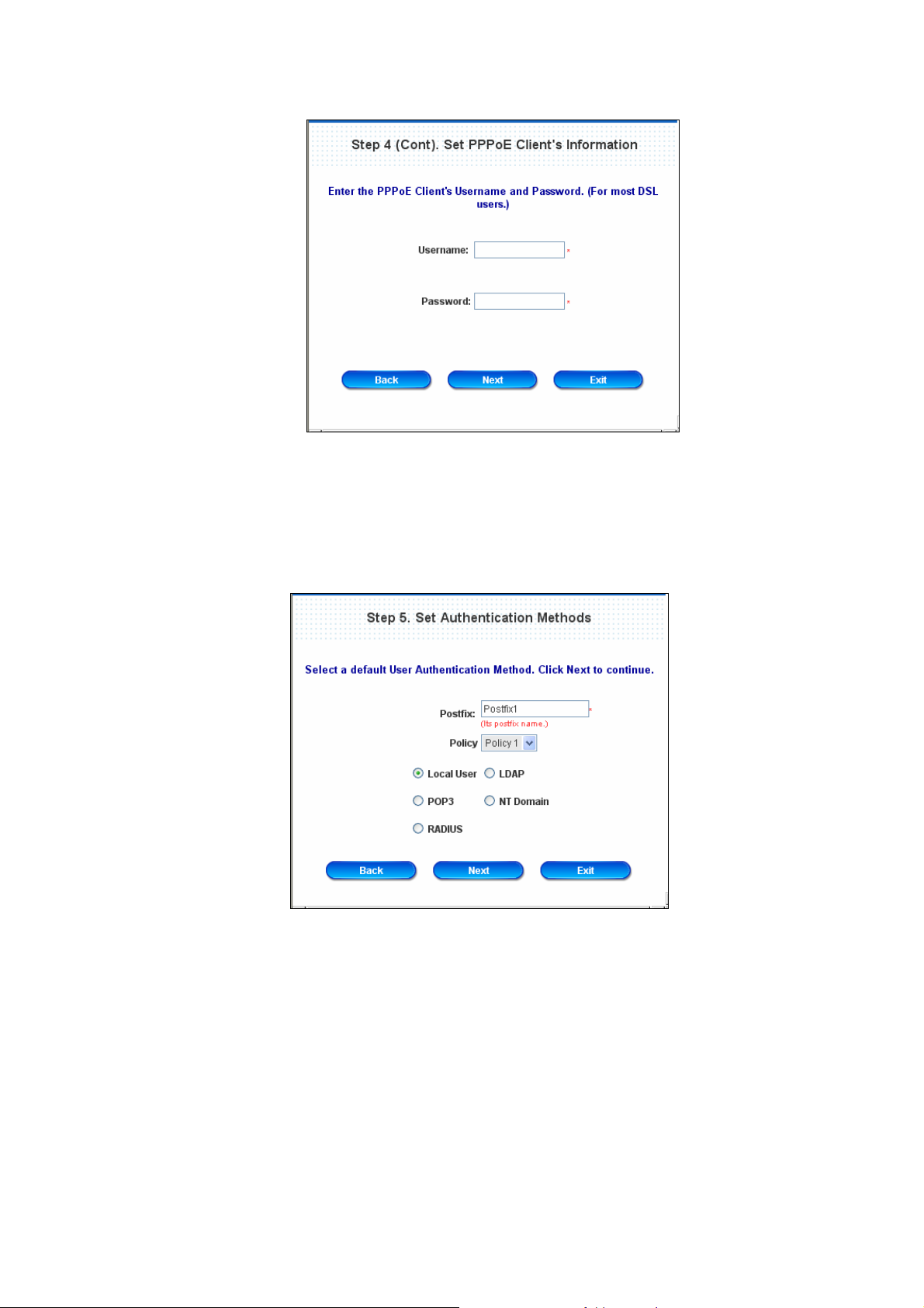
¾ PPPoE Client: Set PPPoE Client’s Information
Enter the “Username” and “Password” provided by the ISP.
Click Next to continue.
y Step 5. Set Authentication Methods
Set the user’s information in advance. Enter an easily identified name as the postfix name in the Postfix
field (e.g. Local), select a policy to assign to, and choose an authentication method.
Click Next to continue. Different information has to be provided for each kind of authentication method:
18
Page 22
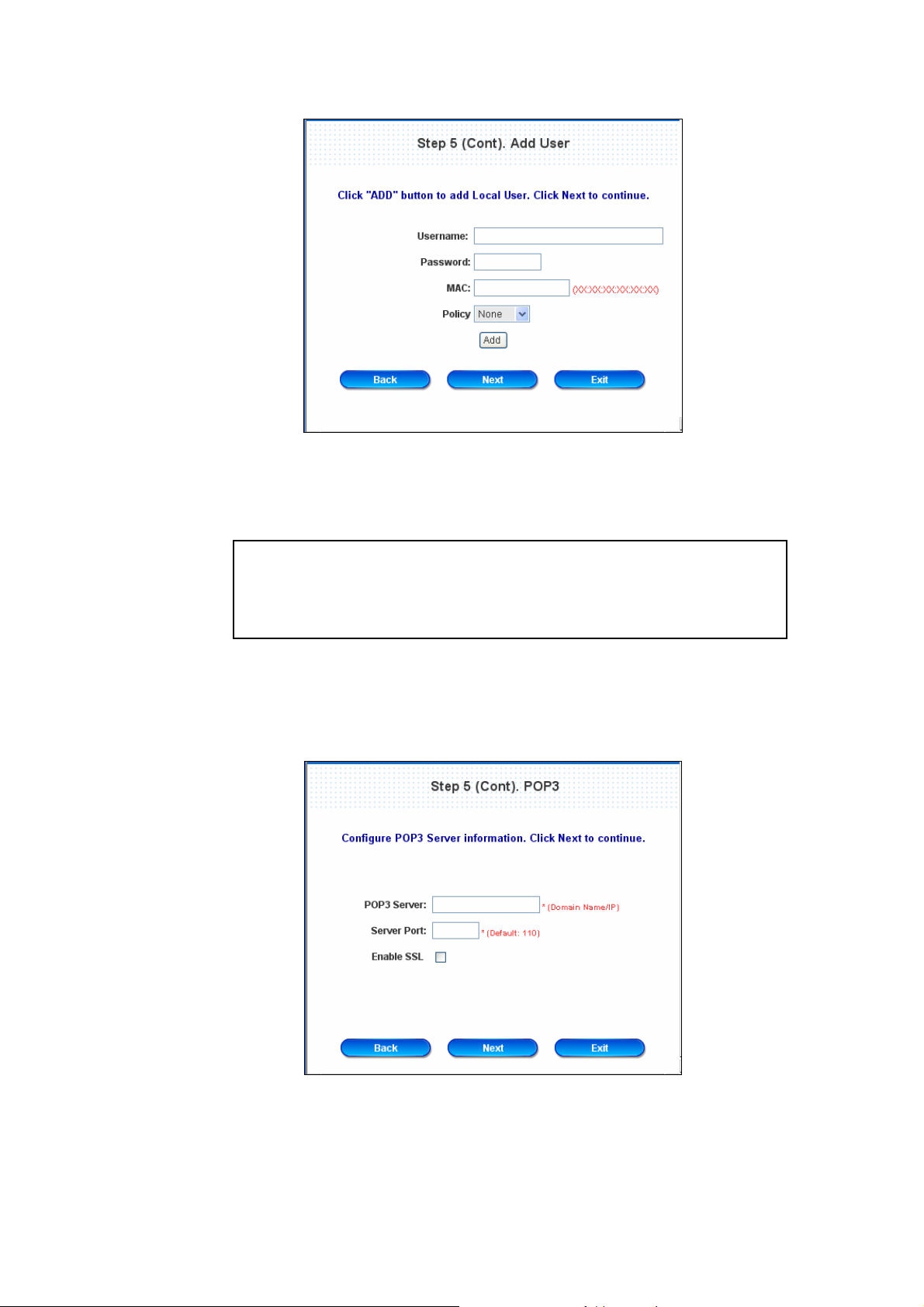
¾ Local User: Add User
A new user can be added to the local user data base. To add a user here, enter the Username (e.g.
test), Password (e.g. test), MAC (optional, to specify the valid MAC address of this user) and assign it
a policy (or use the default). Click the ADD button to add the user..
Attention: The policy selected in this step is applied to this user only.
Per-user policy setting take over the group polic y setting at precious step
unless you select None here. Click Next to continue.
¾ POP3 User: POP3
Enter IP/Domain Name and server port of the POP3 server provided by the ISP, and then choose
enable SSL or not.
Click Next to continue.
19
Page 23
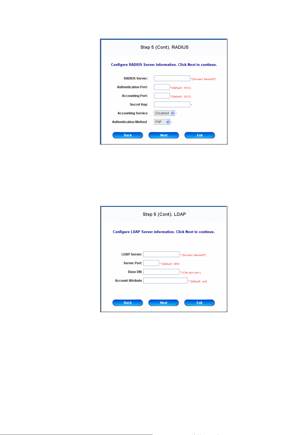
¾ RADIUS User: RADIUS
Enter RADIUS server IP/Domain Name, authentication port, accounting port and secret key. Then
choose to enable accounting service or not, and choose the desired authentication method.
Click Next to continue.
¾ LDAP User: LDAP
Configure external LDAP user data base here. Enter the “LDAP Server”, “Server Port”, “Base DN”
and “Account Attribute”.
Click Next to continue.
20
Page 24
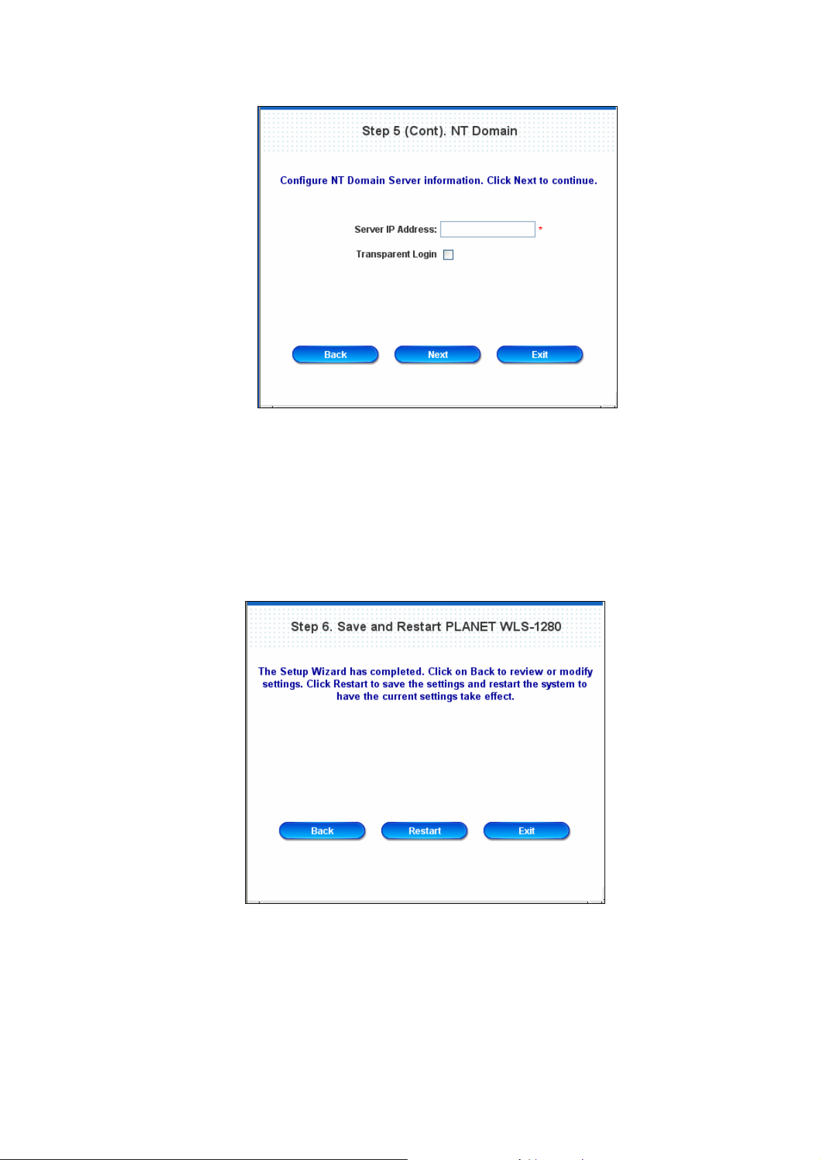
¾ NT Domain User: NT Domain
When NT Domain User is selected, enter the information for “Server IP Address”, and choose to
enable/disable “Transparent Login”.
If “Transparent Login ” is enabled, users are l ogged in PLANET WL S-1280’ s NT Domai n active directory
and authenticated automatically when they log into their Windows OS domain.
Click Next to continue.
y Step 6. Save and Restart PLANET WLS-1280
Click Restart to save the current settings and restart PLANET WLS-1280. The Setup Wizard is now
completed.
y Setup Wizard. During PLANET WLS-1280 re start, a “Rest arting no w. Pleas e wait for a while.” message
will appear on the screen. Please do not interrupt PLANET WLS-1280 until the message has disappeared.
This indicates that a complete and successful restart process has finished.
21
Page 25
Caution: During every step of the wizard, if you wish to go back to modify the settings, please click the Back
button to go back to the previous step.
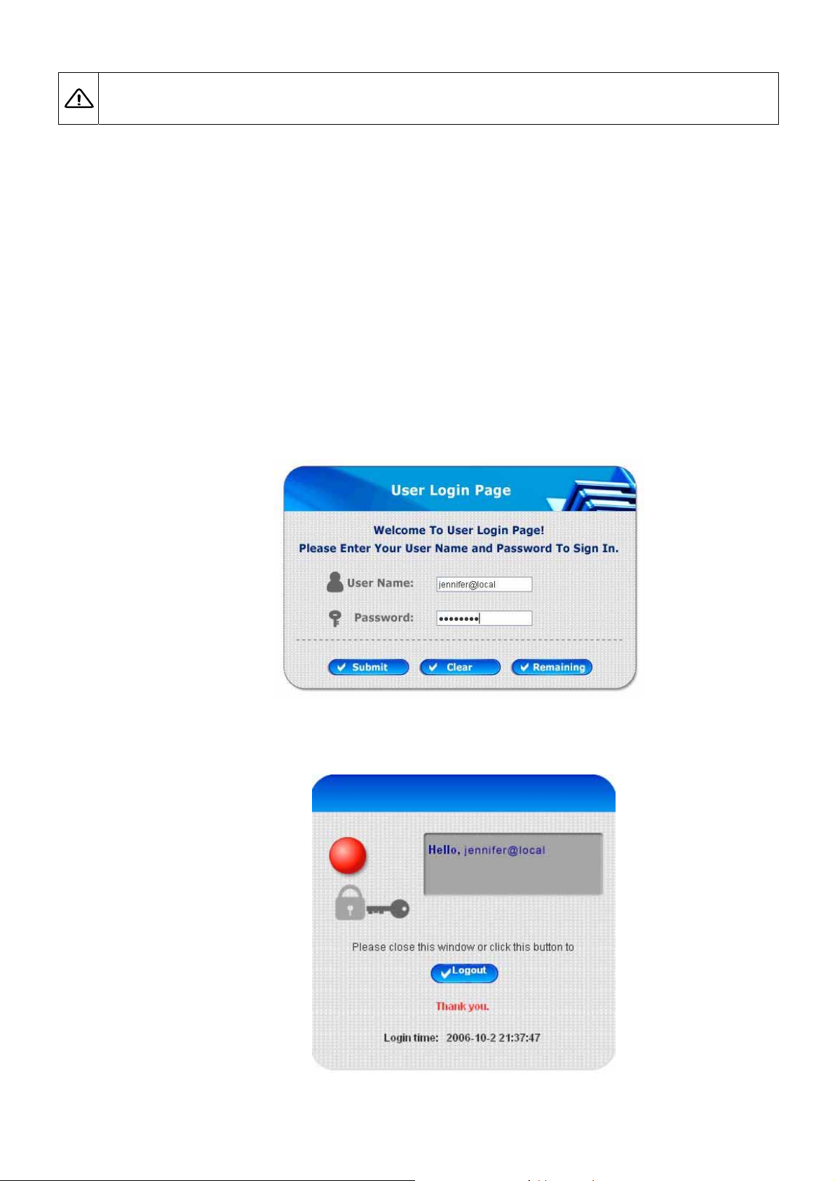
3.2.2 User Login Portal Page
To login from the login portal p age via the co ntrolled port, the user h ave to be identified the user na me and p assword.
The administrator also can verify the correctness of the configuration steps of PLANET WLS-1280.
1. First, connect a user-end device (for example, a PC) to the controlled port of PLANET WLS-1280, and set the
device to obtain IP address automatically. After the client obtains the network address, please open up an
Internet browser and the default login webpage will appear on the Internet browser.
Enter a valid user name and password. Assumeing local user database is chose n in the configuration wizard,
enter the username and password created and then click Submit button (e.g. test@Local for the username and
test for the password).
2. Login succeed page will appear if PLANET WLS-1280 has been installed and configured successfully. Now,
clients can browse the network or surf the Internet.
22
Page 26
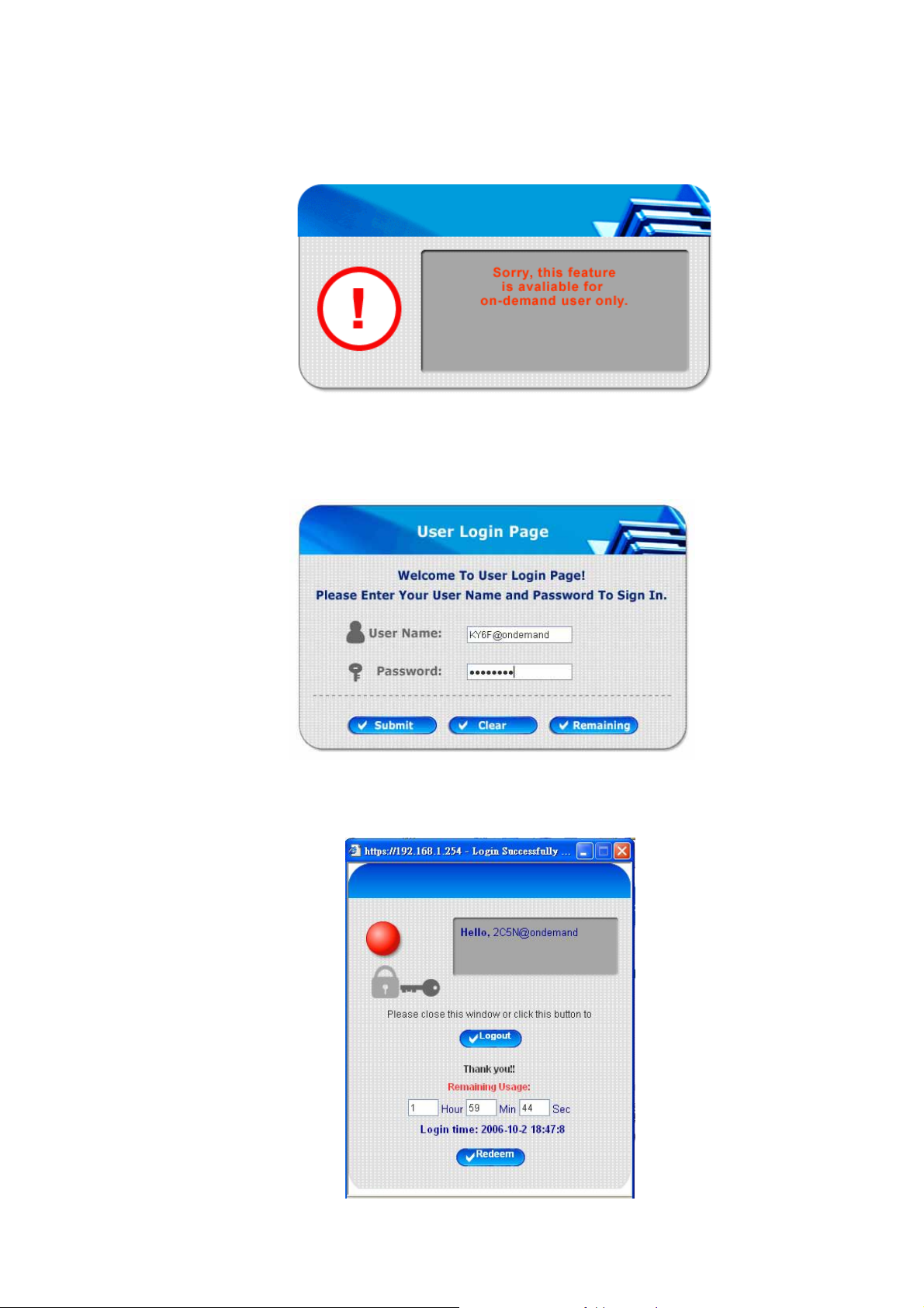
3. If the screen shows “Sorry, this feature is available for on-demand user only ”, it means that the
“Remaining” button has been clicked. This button is only for on-demand use rs only. For clients other than
on-demand users, please click the Submit button.
4. An on-demand user can enter the username and password in the “User Login Page” and click the Remaining
button to view the remaining time the account.
5. When an on-demand user logs in successfully, the following Login Successfully screen will appear. There is
an extra line showing “Remaining usage” and a “Redeem” button.
23
Page 27
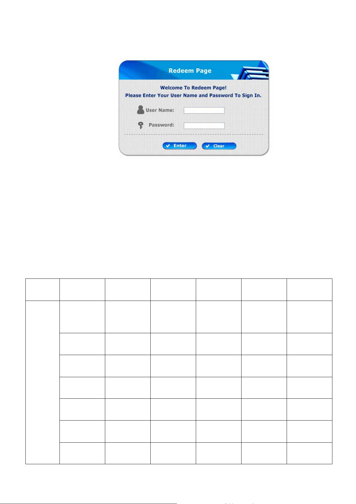
y Remaining usage: Show the remaining time or data volume that the on-demand user can use to surf
Internet.
y Redeem: When the remaining time or data size is insufficient, the client has to pay for adding credit at the
counter, and then, the clie nt will get a new username and password. After clicking the Redeem button, a
login screen will appear . Please enter the new username and password obtained and click Redeem button.
The total available use time and data size after adding credit will show up.
4. Web Interface Configuration
This chapter will guide you through further detailed settings. The following table is the UI and functions of PLANET
WLS-1280.
OPTION
System
Configuration
Configuration
FUNCTION
Wizard
System
Information
WAN1
Configuration
WAN2 &
Failover
User
Authentication
Authentication
Configuration
Black List
Configuration
Policy
Configuration
Additional
Configuration
AP
Management
AP List
AP Discovery Privilege List
Manual
Configuration
Template
Settings
Network
Configuration
Network
Address
Translation
Monitor IP List
Walled Garden
List
Utilities Status
Change
System Status
Password
Backup/Restore
Interface Status
Settings
Firmware
Current Users
Upgrade
Restart Traffic History
LAN Port Roles
Controlled
Configuration
Uncontrolled
Configuration
Firmware
Management
AP Upgrade Dynamic DNS
IP Mobility
24
Proxy Server
Properties
Notification
Configuration
Page 28

VPN
Termination
Caution: After finishing the configuration of the settings, please click Apply and pay attention to see if a
restart message appears on the screen. If such message appears, system m ust be restarted to allow the
settings to take effect. All on-line users will be disconnected during restart.
25
Page 29
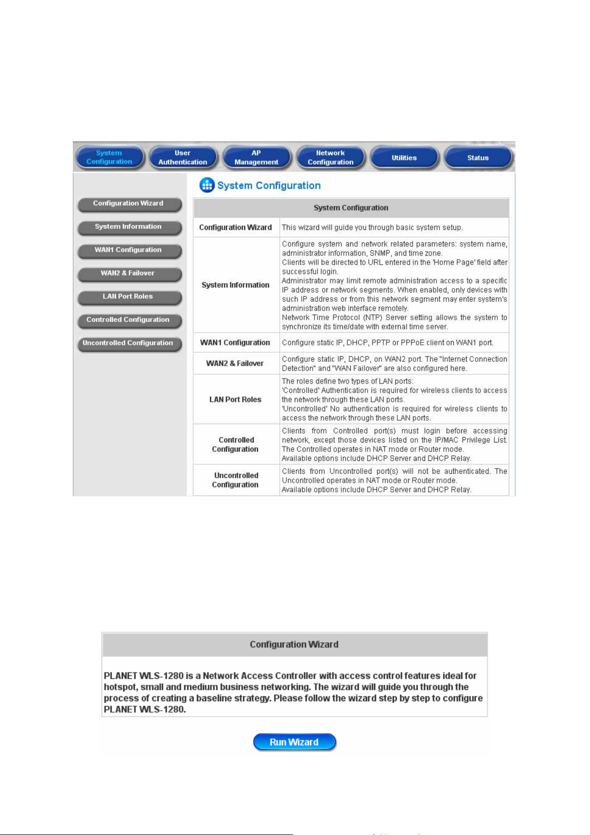
4.1 System Configuration
This section includes the following functions: Configuration Wizard, System Information, WAN1 Configuration,
WAN2 & Failover, LAN Port Role s, Controlled Configuration and Uncontrolled Configuration.
4.1.1 Configuration Wizard
There are two ways to configure the system: using Configuration Wizard or change the setting by demands
manually. The Configuration Wizard has 6 steps providing a simple and easy way to go through the basic setups of
PLANET WLS-1280 and is served as Quick Configuration. Please refer to 3.2.2 Quick Configuration for the
introduction and description of Configuration Wizard.
26
Page 30
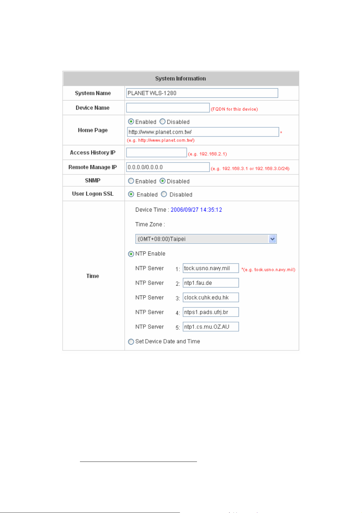
4.1.2 System Information
Most of the major system information about PLANET WLS-1280 can be set here. Please refer to the following
description for each field:
y System Name: Set the system’s name or use the default.
y Device Name: Enter an identifiable name for this device.
y Home Page: Enter the website of a Web Server to be the homepage. When users log in successfully, they will
be directed to the homepage set. Usually, the homepage is the company’s website, such as
http://www.yahoo.com. Regardl ess of the original webpage set in the users’ computers, they will be redirect to
this page after login.
y Access History IP: Specify an IP address of the administrator’s computer or a billing system to get billing
history information of PLANET WLS-1280 with fix format URLs.
Traffic Hist o ry :
https://10.2.3.213/status/history/2005-02-17
27
Page 31

On-demand History:
https://10.2.3.213/status/ondemand_history/2005-02-17
y Remote Manage IP: Set the IP range which is able to connect to the web management interface via WAN
and/or controlled port. For example, 10.2.3.0/24 means that as long as you are within the IP address rang e of
10.2.3.0/24, you can reach the administration page of PLANET WLS-1280. If the IP range bit number is omitted,
32 is used to specify a single IP address.
y SNMP: PLANET WLS-1280 supports SNMPv2. If the function is enabled, it is able to assign the Manager IP
address and the SNMP community name used to access the management information base (MIB) of the
system.
y User Logon SSL: Enable to activate https (encryption) or disable to activate http (non encryption) login page.
y Time: PLANET WLS-1280 supports NTP communication protocol to synchronize the system time with remote
time server. Please spe cify the local time zone and IP address of at least one server in the system configuration
interface for adjusting the time automatically . (Universal Time is Greenwich Mean Time, GMT). T ime ca n also be
set manually when selecting “Set Device Date and Time”. Please enter the date and time for these fields.
28
Page 32

4.1.3 WAN1 Configuration
There are 4 connection types for the WAN1 Port: Static IP Address, Dynamic IP Address, PPPoE Client and
PPTP Client.
29
Page 33

y Static IP Address: Manually specifying the IP address of the WAN1 Port is applicable for the network
environment where the DHCP service is unavailable. The fields with red asterisks are required to be filled in.
IP Address: the IP address of the WAN1 port.
Subnet Mask: the subnet mask of the WAN1 port.
Default Gateway: the gateway of the W A N1 port.
Preferred DNS Server: The primary DNS Server of the WAN1 port.
Alternate DNS Server: The substitute DNS Server of the WAN1 port. This is not required.
y Dynamic IP address: It is only applicable for the network environment where the DHCP Server is available in
the network. Click the Renew button to get an IP address.
y
PPPoE Client: Common ADSL connection type. When selecting PPPoE to connect to the network, please set
the “Username”, “Password”, “MTU” and “CLAMPMSS”. There is a Dial on Demand function under PPPoE.
If this function is enabled, a Maximum Idle Time can be set. When the idle time is reached, the system will
automatically disconnect itself
y PPTP Client: Point to Point Tunneling Protocol is a service that applies to broadband connections used mainly
in Europe and Israel. Select STA TIC to specify the IP address of the PPTP Client manually or select DHCP to
get the IP address automatically. The fields with red asterisks are required to be filled in. There is a Dial on
Demand function under PPPTP. If this function is enabled, a Maximum Idle Time can be set. When the idle
time is reached, the system will automatically disconnect itself
30
Page 34

4.1.4 WAN2 & Failover
Except selecting None to disable this function, there are 2 connection types for the WAN2 port: Static IP Address
and Dynamic IP Addres s. Up to three URLs can be e ntered. Check “Warning of Internet Disconnection” to work
with the WAN Failover function. When Warning of Internet Disconnection is enabled, the system will check the
three URLs to detect the WAN ports connection status.
31
Page 35

y None: The WAN2 Port is disabled. Up to three URLs can still be entered. Check “Warning of Internet
Disconnection” to detect the WAN1 port connection status.
y Static IP Address: S pecify the IP Address, Subnet Mask and Default Gateway of WAN2 Port, which should be
applicable for the network environment. Up to three URLs can be entered. Check “W arning of Internet
Disconnection” to work with the WAN Failover function.
If WAN Failover function is enabled, when WAN1 connection fails, the traffic will be routed to WAN2
32
Page 36

automatically. If Fallback to WAN1 when possible function is enabled, when WAN1 connection is recovered,
the routed traffic will be back to WAN1.
y Dynamic IP Address: Select this when WAN2 Port can obtain IP address automatically, su ch as a DHCP
Server available from WAN2 Port. Up to three URLs can be entered. Check “Warning of Internet
Disconnection” to work with the WAN Failover function.
For Dynamic IP Address, WAN Failover and Fallback to WAN1 when possible also can be enabled like as
the function for Static IP Address. If W arning of Internet Disconnection is enabled, a warning message can
be entered to indicate what the system should display when Internet connection is down.
4.1.5 LAN Port Roles
Client machines connect to PLANET WLS-1280 via LAN ports. Each LAN port can be configu red to one of two roles,
controlled or uncontrolled. The differences of these two roles for a client connected to are: Clients connected to
controlled port to need authentication to access network; Clients conne cted to uncontrolled p ort can a ccess the we b
management interface.
33
Page 37

4.1.6 Controlled Configuration
The controlled port has the user authentication function which can be enabled or disabled.
y Controlled
Operation Mode: Choose one of the two modes, NAT mode and Router mode, by the requirements.
IP Address: Enter the desired IP address for the controlled port.
Subnet Mask: Enter the desired subnet mask for the controlled port.
y DHCP Server Configuration
There are three methods to set the DHCP server: Disable DHCP Server, Enable DHCP Server and Enable
DHCP Relay.
1. Disable DHCP Server: Disable DHCP Server function.
2. Enable DHCP Server: Choose “Enable DHCP Sever” function and set the appropriate configuration for
the DHCP server. The fields with red mark are required. Please fill in these fields.
34
Page 38

DHCP Scope: Enter the “Start IP Address” and the “End IP Address” of this DHCP block. These fields
define the IP address range that will be assigned to the Control Port clients.
Preferred DNS Server: The primary DNS server for the DHCP.
Alternate DNS Server: The substitute DNS server for the DHCP.
Domain Name: Enter the domain name.
WINS Server IP: Enter the IP address of WINS
Lease Time: Choose the time to change the DHCP.
Reserved IP Address List: For reserved IP address settings in detail, please click the hyperlink of
Reserved IP Address. Click on the Reserved IP Address List on the management interface to use the
Reserved IP Address List function. Reserved IP Address List as shown in the following figure will appear.
Enter the related Reserved IP Address, MAC, and some description (not compulsory). When finished, click
Apply to complete the setup.
35
Page 39

3. Enable DHCP Relay: Another DHCP Server IP address must be specified to enable this function. See the
following figure.
4.1.7 Uncontrolled Configuration
The uncontrolled port doesn’t have to authenticate clients before they can access the network. In this section, you
can set the related configuration for uncontrolled port and DHCP server.
36
Page 40

y Uncontrolled
Operation Mode: Choose one of the two modes, NAT mode and Router mode, by the requirements.
IP Address: Enter the desired IP address for the uncontrolled port.
Subnet Mask: Enter the desired subnet mask for the uncontrolled port.
y DHCP Server Configuration
There are three methods to set the DHCP server: Disable DHCP Server, Enable DHCP Server and Enable
DHCP Relay.
1. Disable DHCP Server: Disable DHCP Server function.
2. Enable DHCP Server: Choose “Enable DHCP Sever” function and set the appropriate configuration for
the DHCP server. The fields with red mark are required. Please fill in these fields.
37
Page 41

DHCP Scope: Enter the “Start IP Address” and the “End IP Address” of this DHCP block. These fields
define the IP address range that will be assigned to the Private LAN clients.
Preferred DNS Server: The primary DNS server for the DHCP.
Alternate DNS Server: The substitute DNS server for the DHCP.
Domain Name: Enter the domain name.
WINS Server IP: Enter the IP address of WINS.
Lease Time: Choose the time to change the DHCP.
Reserved IP Address List: For reserved IP address settings in detail, please click the hyperlink of
Reserved IP Address. If using the Reserved IP Address List function i s desire d, click on the Rese rv ed IP
Address List on the management interface. Then, the setup of the Reserved IP Address List as shown in
the following figure will appear. Enter the related Reserved IP Address, MAC, and some description (not
compulsory). When finished, click Apply to complete the setup.
38
Page 42

3. Enable DHCP Relay: If you want to enable this function, you must specify other DHCP Server IP address.
See the following figure.
39
Page 43

4.2 User Authentication
This section includes the following functions: Authentication Configuration, Black List Configuration, Policy
Configuration, and Additional Configuration.
4.2.1 Authentication Configuration
This function is used to configure the settings for authentication server and on-demand user authentication. Click on
the server name to set the related configurations for that particular server. Users can log into the default server
without the postfix to allow faster login process.
40
Page 44

y Server 1~3: There are 5 kinds of authentication methods, Local User, POP3, RADIUS, LDAP and NTDomain to
setup from.
Server Name: Set a name for the server using numbers (0 to 9), alphabets (a to z or A to Z), dash (-),
underline (_) and dot (.) with a maximum of 40 characters, all other letters are not allowed.
Sever Status: The status shows that the server is enabled or disabled.
Postfix: Set a postfix that is easy to distingui sh (e.g. Local) for the server using numbers (0 to 9), alphabets (a
to z or A to Z), dash (-), underline (_) and dot (.) with a maximum of 40 characters, all other letters are not
allowed.
Black List: There are 5 sets of black lists. Select one of them or choose “None”. Please refer to 4.2.2 Black
List Configuration for more information.
Authentication Method: There are 5 authentication methods, Local, POP3, RADIUS, LDAP and NT Domain
to configure from. Select the desired method and then click the link besides the pull-down menu for more
advanced configuration. For more details, please refer to 4.2.1.1~5 Authenticati on Method.
Notice: Enabling two or more servers of the same authentication method is not allowed.
Policy: There are 3 policies to choose from to apply to this particular server.
41
Page 45

y On-demand User: When the customers need to use wireless Internet in the store, they have to get a printed
receipt with username and password from the store to log in the system for wireless access. There are 2000
On-demand User accounts available.
Server Status: The status shows that the server is enabled or disabled.
Postfix: Set a postfix that is easy to distingui sh (e.g. Local) for the server using numbers (0 to 9), alphabets (a
to z or A to Z), dash (-), underline (_) and dot (.) with a maximum of 40 characters, all other letters are not
allowed.
Receipt Header: There are two fields, Receipt Header 1 and Receipt Header 2, for the receipt’s header.
Enter receipt header message or use the default.
Receipt Footer: Enter receipt footer message here or use the default.
Monetary Unit: Select or enter the desired monet ary unit.
Policy Name: Select a policy for the on-demand user.
WLAN ESSID: Enter the ESSID of the AP.
Wireless Key: Enter the Wireless key of the AP.
Remark: Enter any additional information that will appear at the bottom of the receipt.
Billing Notice Interval: While a volume type on-demand user is still logged in, the system will update the
billing notice of the login successful page by the time interval defined here.
42
Page 46

User List: Click to enter the On-demand User List screen. In the On-demand User List, detailed information
will be documented here.
¾ Search: Enter a keyword of a username to be searched in the text field and click this button to perform the
search. All usernames matching the keyword will be listed.
¾ Username: The login name of the on-demand user.
¾ Password: The login password of the on-demand user.
¾ Remain Time/Volume: The total time/Volume that the user can use currently.
¾ Status: The status of the account. Normal indicates that the account is not in-use and not overdue. Online
indicates that the account is in-use and not overdue. Expire indicates that the account is overdue and
cannot be used.
¾ Expire Time: The expiration time of the account.
¾ Delete All: This will delete all the users at once.
¾ Delete: This will delete the users individually.
43
Page 47

Billing Configuration: Click this to enter the Billing Configuration page. In the Billing Configuration screen,
Administrator may configure up to 10 billing plans.
¾ Status: Select to enable or disable this billing plan.
¾ Type: Set the billing plan by “Volume” (the maximum volume allowed is 99 99999 Mbyte) or “Time” (the
maximum time allowed is 999 hours and 59 minutes).
¾ Expired info: This is the duration of time that the user needs to activate the account af ter the generation of
the account. If the account is not activated during this duration, the account will self-expire.
¾ Valid Duration: This is the duration of time that the user can use the account after the activation of the
account. After this duration, the account will self-expires.
¾ Price: The price charged for this billing plan.
44
Page 48

Create On-demand User: Click this to enter the On-demand User Generate page.
Pressing the Create button for the desired rule, an On-demand user will be created, then click Printout to
print a receipt which will contain this on-demand user’s information. There are 2000 On-demand user
accounts available.
45
Page 49

Billing Report: Click this to enter the On-demand users Summary report page. In On-demand users
Summary report page, Administrator can get a complete report or a report of a particular period.
¾ Report All: Click this to get a complete
report including all the on-demand
records. This report shows the total
expenses and individual accounting of
each plan for all plans available.
¾ Search: Select a time period to get a
periodical report. The report tells the
total expenses and individual
accounting of each plan for all plans
available for that period of time.
46
Page 50

4.2.1.1 Authentication Method – Local User Setting
Choose “Local User” in the Authentication Method field, the hyperlink beside s the pull-down menu will become
“Local User Setting”.
Click the hyperlink to get in for further configuration.
y Edit Local User List: Click this to enter the “Local User List” page.
y Add User: Click this to enter the Add User interface. Fill in the necessary information such as “Username”,
“Password”, “MAC” (optional) and “Remark” (optional). Select a desired Policy, check whether to ena ble
VPN Termination.
47
Page 51

Click Apply to save all the settings after finishing to add users.
Upload User: Click this to enter the Upload User interface. Click the Browse button to select t he text file for the
user account upload. Then click Submit to complete the upload process.
48
Page 52

The uploading file should be a text file and
the format of each line is "ID, Password, MAC, Policy, Remark,
IPSec" without the quotes. There must be no spaces between the fields and commas. The MAC field could be
omitted but the trailing comma must be retained. The Group field indicate s policy number to use. When adding
user accounts by uploading a file, the existing accounts in the embedd ed database will not be replaced by new
ones. If you want user Enable VPN Termination, please set IPSec field to 1 to enable VPN, or 0 to disable VPN.
Download User: Click this to enter the Users List page and the system will directly show a list of all created
user accounts. Click Download to create a .txt file and then save it on disk.
Refresh: Click this to renew the User List page.
49
Page 53

Search: Enter a keyword of a username that you wish to search in the text filed and click this button to perform
the search. All usernames matching the keyword will be listed.
Del All: This will delete all the users at once.
50
Page 54

Delete: This will delete the users individually.
Edit User: If you want to edit the content of individual user account, click the username of the desired user
account to enter the User Profile Interface for that particular user, and then modify or add any desired
information such as “Username”, “Password”, “MAC” (optional) and “Remark” (optional). Then check “VPN
Termination” to enable this function or not. Click Apply to complete the modification.
y Radius Roaming Out / 802.1x Authentication: Ra dius Roaming Out / 802.1x Authentication: These 2
functions can be enabled or disabled by checking the correct button. Checking either of them make s the
hyperlink called Radius Client List show up.
y
Click the hyperlink of Radius Client List to enter the Radius Client Configuration page. Choose the desired
type, Disable, Roaming Out or 802.1x and key in the related data and then click Apply to complete the
settings.
Radius Roaming Out: When “Radius Roaming Out” is selected, local users can login from other domains by
using their original accounts.
51
Page 55

802.1x Authentication: 802.1x is a security standard for wired and wireless LANs. It encapsulates EAP
(Extensible Authentication Protocol) processes into Ethernet packets instead of using the protocol's native PPP
(Point-to-Point Protocol) environment, thus reducing some network overhead. It also puts the bulk of the
processing burden upon the client (called a supplicant in 802.1x parlance) and the authentication server (such
as a RADIUS), letting the "authenticator" middleman simply pass the packets back and forth.
4.2.1.2 Authentication Method – POP3
Choose “POP3” in the Authentication Method field, the hyperlink beside the pull-down m enu will become “POP3
Setting”.
When POP3, Radius, LDAP or NTDomain is selected from the drop-down memu, “Enable VPN Termination” will
show up. Check “Enable VPN Termination” to enable this function. Click the hyperlink for further co nfiguration.
Enter the related information for the primary server and/or the secondary server (the secondary server is not
required). The blanks with red star are necessary info rmation. These settings will become ef fective immediat ely after
clicking the Apply button.
y Server IP: Enter the IP address/domain name given by the ISP.
y Port: Enter the Port given by the ISP. The default value is 100.
y Enable SSL Connection: If this option is enabled, the POP3s protocol will be used to encrypt the
52
Page 56

authentication.
4.2.1.3 Authentication Method – Radius
Choose “Radius” in the Authentication Method field, the hyperlink beside the pull-down menu will become
“Radius Setting”.
When POP3, Radius, LDAP or NTDomain is selected from the drop-down memu, “Enable VPN Termination” will
show up. Check “Enable VPN Termination” to enable this function or not. Click the hyperlink for further
configuration. The Radius server sets the external auth entication for use r accounts. Enter the related information for
the primary server and/or the secondary server (the secondary server is not req uired). The blanks with red star are
necessary information. These settings will become effective immediately after clicking the Apply button.
53
Page 57

y 802.1X Authentication: Enable this function and the hyperlink of Radius Client List will appear. Click the
hyperlink to get into the Radius Client Configuration list for further configuration. In the Radius Client
Configuration page, the clients, which are using 802.1X as the authentication method, shall be put into this
table. PLANET WLS-1280 will forward the authentication request from these clients to the configured Radius
Servers.
54
Page 58

y Trans Full Name: When e nable d, the ID and po stfix will be transferred to the RADIUS server for authentication.
When disabled, only the ID will be transferred to RADIUS server for authentication.
y NASID: Enter the NASID of PLANET WLS-1280 for the RADIUS server.
y Server IP: Enter the IP address/domain name of the RADIUS server.
y Authentication Port: Enter the authentication port of the RADIUS server and the default valu e is 1812.
y Accounting Port: Enter the accounting port of the RADIUS server and the default value is 1813.
y Secret Key: Enter the key for encryption and decryption.
y Accounting Service: Select this to enable or disable the “Accounting Service” for accounting capabilities.
y Authentication Protocol: There are two methods, CHAP and PAP for selection.
y Policy Mapping: Enable or disable policy mapping by RADIUS class attributes.
y
55
Page 59

y Class Attribute: Class attribute sent from the RADIUS server.
y Policy: Select the mapping policy of this class attribute.
y Remark: Add some description if needed.
4.2.1.4 Authentication Method – LDAP
Choose “LDAP” in the Authentication Method field, the hyperlink beside the pull-down menu will become “LDAP
Setting”.
When POP3, Radius, LDAP or NTDomain is selected from the drop-down memu, “Enable VPN Termination” will
show up. Check “Enable VPN Termination” to enable this function or not. Click the hyperlink for further
configuration. Enter the related information for the primary server and/or the secondary server (the seconda ry server
is not required). The blanks with red star are necessary information. These settings will become effective
immediately after clicking the Apply button.
56
Page 60

y Server IP: Enter the IP address or domain name of the LDAP server.
y Port: Enter the Port of the LDAP server, and the default value is 389.
y Base DN: Enter the distinguished name of the LDAP server.
y Account Attribute: Enter the account attribute of the LDAP server.
4.2.1.5 Authentication Method – NTDomain
Choose “NTDomain” in the Authentication Method field, the hyperlink beside the pull-down menu will become
“NTDomain Setting”.
When POP3, Radius, LDAP or NTDomain, is selected from the drop-down memu “Enable VPN Termination” will
show up. Check “Enable VPN Termination” to enable this function or not. Click the hyperlink for further
configuration. Enter the server IP address and enable/disable the transparent login function. These settings will
become effective immediately after clicking the Apply button.
y Server IP address: Enter the server IP address of the domain controller.
y Transparent Login: If the function is enabled, when users log into the Windows domain, they will log into
PLANET WLS-1280 automatically
4.2.2 Black List Configuration
The administrator can add, delete, or edit the black list for user access control. Each black list can incl ude 40 users
at most. If a user in the black list wants to log into the system, the user’s access will be denied. The administrator
57
Page 61

can use the pull-down menu to select the desired black list.
y Select Black List: There are 5 lists to select from for the desired black list.
y Name: Set the black list name and it will show on the pull-down menu above.
y Add User to List: Click the hyperlink to add users to the selected black list.
After entering the usernames in the “Username” blanks and the related information in the “Remark” blank (not
required).
58
Page 62

Click Apply to save the settings.
If the administrator wants to remove a user from the black list, just select the user’s “Delete” check box and
then click the Delete button to remove that user from the black list.
59
Page 63

4.2.3 Policy Configuration
Each policy has three profiles, Firewall Profile, Specific Route Profile, and Schedule Profile as well as
Bandwidth settings for that policy.
y Firewall Profile
Click the hyperlink of Setting for Firewall Profile, the Firewall Profile page will appear. Click the numbers of
Filter Rule Item to edit individual rules and click Apply to save the settings. The rule status will show o n the list.
Check “Active” to enable that rule.
Attention: Filter Rule Item 1 is the highest priority, Filter Rule Item 2 is the second priority, and so on.
60
Page 64

Rule Item: This is the rule selected.
Rule Name: The rule name can be changed here. The rule name can be set to easily identify, for example:
“from file server”, “HTTP reques t” or “to web”, etc.
Enable this Rule: After checking this function, the rule will be enabled.
Action: There are two options, Block and Pass. Block is to p revent p ack ets f rom p assi ng an d Pass is to permit
packets passi ng.
Protocol: There are three protocols to select, TCP, UDP and ICMP, or choose ALL to use all three protocols.
Source MAC Address: Th e MAC address of the source IP address. This is for specific MAC address filter.
Source/Destination Interface: There are four interfaces to choose, ALL, WAN1, WAN2, Controlled Port and
Uncontrolled Port.
61
Page 65

Source/Destination IP: Enter the source and destination IP addresses.
Source/Destination Subnet Mask: Enter the source and destination subnet masks.
Source/Destination Start/End Port: En ter the range of source and destination ports.
y Specific Route Profile
Click the hyperlink of Setting for Specific Route Profile, the Specific Default Route and Specific Route
Profile page will appear.
Specific Default Route
Enable: Click to enable the setting of specific default route.
Default Gateway: There are 3 methods of the default gateway that Specific Default Route supports. Select
WAN1 Default Gateway to set WAN1 as the default gateway. Select WAN2 Default Gateway to set WAN2 as
the default gateway. Select IP Address and enter the IP address of the specific route r.
Specific Route Profile
Profile Name: The profile name can be changed here.
Destination IP Address: The destination IP address of the host or the network.
62
Page 66

Destination Subnet Netmask: Select a destination subnet netmask of the host or the network.
Gateway IP Address: The IP address of the gateway or the router to the destination.
y Schedule Profile
Click the hyperlink of Setting for Schedule Profile to enter the Schedule Profile list. Select “Enable” to show
the list. This function is used to restrict the time the users can log in. Please enable/disable the desired time slot
and click Apply to save the settings. These settings will becom e effective immediately after clicking the Apply
button.
63
Page 67

y Total Bandwidth
Select the bandwidth from the drop-down menu. It’s the total bandwidth the users under this particular policy
need to share.
y Individual Maximum Bandwidth
Select the bandwidth from the drop-down menu. It’s t he mo st ban dwid th an indiv idual u ser ca n obt ain und er this
particular policy, which cannot exceed the value for Total Bandwidth.
y Individual Request Bandwidth
Select the bandwidth from the drop-down menu. It’s the requested bandwidth for an user under this particular
policy, which cannot exceed the value for Individual Maximum Bandwidth.
4.2.4 Additional Configuration
y User Control: Functions under this section applies for all general users.
Idle Timer: If a user has been idled with no network activities, the system will automatically kick out the user.
The logout timer can be set in the range of 1~1440 minutes, and the default logout time is 10 minutes.
Multiple Login: When enabled, the same account can be logged in by different clients at the same time. (This
function doesn’t support On-demand users and RADIUS server)
Friendly Logout: When a user logs into the network, a small window will appear to show the user’s information
and there is a logout button for the logout. If enabled. When the users try to close the small window , there will be
64
Page 68

a new popup window to confirm the logout in case the users click the logout button by accident.
y Roaming Out Timer
Session Timeout: The time that the user can access the network while roamin g. When the time is up, the user
will be kicked out automatically.
Idle Timeout: If a user has been idled with no network activities, the system will automatically kick out the user.
Interim Update: The system will update the users’ current status and usage according to this time periodically.
y Upload File
1. Certificate: The administrator can upload new private key and customer certification. Click the Browse
button to select the file for the certificate upload. Then click Submit to complete the upload process.
Click Use Default Certificate to use the default certificate and key.
2. Login Page: The administrator can use the default login page or get the custo mized login page by setting
the template page, uploading the page or downloading from the specific website. After finishing the setting,
you can click Preview to see the login page.
a. Choose Default Page to use the default login page.
65
Page 69

b. Choose Template Page to make a customized login page here. Click Select to pick up a color and then
fill in all of the blanks. Click Preview to see the result first.
c. Choose Uploaded Page and upload a login page. Click the Browse button to select the file to upload.
Then click Submit to complete the upload process.
66
Page 70

After the upload process is completed, the new login page ca n be previewed by clicking Preview button at
the bottom.
The user-defined login page must include the following HTML codes to provide the necessary fields for
username and password.
67
Page 71

If the user-defined login page includes an image file, the image file path in the HTML code must be the
image file you will upload.
Then, enter or browse the filename of the images to upload in the Upload Images field on the Upload
Images Files page and then click Submit. The system will show the used space and the maximum size of
the image file of 512K. If the administrator wishes to restore the factory default of the login page, click the
Use Default Page button to restore it to default.
After the image file is uploaded, the file name will show on the “Existing Image Files” field. Check the file
and click Delete to delete the file.
In PLANET WLS-1280, the end user first gets a login pag e wh en she/he opens its web browser right after
associating with an access point. However, in some situations, the hotspot owners or MIS staff may want to
display “terms of use” or announcement information before the login page. Hotspot own ers or MIS staff can
design a new disclaimer/announcement page and save the page in their local server. After the agreement
shown on the page is read, users are asked whether they agree or disa gree with the disclaimer. By clicking I
agree, users are able to log in. If users choose to decline, they will get a popup window saying they are unable
to log in. The basic design is to have the disclaimer and login function in the same page but wi th the login
function hidden until users agree with the disclaimer.
For more details about the codes of the disclaimer, please refer to Appendix F.
If the page is successfully loaded, an upload success page will show up.
68
Page 72

“Preview” can be clicked to see the uploaded page.
If user checks “I agree” and clicks Next, then he/she is prompted to fill in the login name and password.
If user checks “I disagree” and clicks Next, a window will pop up to tell user that he/she cannot log in
69
Page 73

d. Choose the External Page selection and get the login page from the specific website. Enter the website
address in the “External Page Setting” field and then click Apply.
After applying the setting, the new login page can be previewed by clicking Preview button at the bottom
of this page.
70
Page 74

3. Logout Page: The users can apply their own logout page here. The process is similar to that of Logout
Page.
The different part is the HTML code of the user-defined logout interface must include the following HTML
code that the user can enter the username and password. After the upload is completed, the user-defined
login user interface can be previewed by clicking Preview at the bottom of this page. If want to restore the
factory default setting of the logout interface, click the “Use Default Page” button.
71
Page 75

4. Login Success Page: The administrator can use the default login success page or get the customized login
success page by setting the template page, uploading the page or using the external website. After finishing
the setting, you can click Preview to see the login success page.
a. Choose Default Page to use the default login success page.
b. Choose Template Page to make a customized login success page here. Click Select to pick up a color
and then fill in all of the blanks. You can click Preview to see the result first.
72
Page 76

c. Choose Uploaded Page and you can get the login success page by uploading. Click the Browse button
to select the file for the login success page upload. Then cli ck Submit to comple te the upload process.
After the upload process is completed, the new login success p age can be previewed by clicking Preview
button at the bottom.
If the user-defined login success page includes an image file, the image file path in the HTML code must be
the image file you will upload.
Then, enter or browse the filename of the images to upload in the Upload Images field on the Upload
Images Files page and then click Submit. The system will show the used space and the maximum size of
the image file of 512K. If the administrator wishes to restore the factory default of the login success page,
click the Use Default Page button to restore it to default.
73
Page 77

After the image file is uploaded, the file name will show on the “Existing Image Files” field. Check the file
and click Delete to delete the file.
d. Choose the External Page selection and you can get the login success page e from the specific website.
Enter the website address in the “External Page Setting” field and then click Apply. After applying the
setting, the new login success page can be previewed by clicking Preview button at the bottom of this
page.
5. Login Success Page for On-Demand: The administrator can u se the default login success page for
On-Demand or get the customized login success page for On-Demand by settin g the template page,
uploading the page or using the external website. After finishing the setting, you can click Preview to see
the login success page for On-Demand.
a. Choose Default Page to use the default login success page for On-Demand.
74
Page 78

b. Choose Template Page to make a customized login success page for On-Dema nd here. Click Select to
pick up a color and then fill in all of the blanks. You can click Preview to see the result first.
c. Choose Uploaded Page and you ca n get the Login Success Page Section for On-Demand Users.
Click the Browse button to select the file for the login success pag e for On-Demand. Then click Submit
to complete the upload process.
75
Page 79

After the upload process is completed, the new login success p age for On-Demand can be previewed by
clicking Preview button at the bottom.
If the user-defined login success page for On-Deman d inclu des an image file, the image file path in the
HTML code must be the image file you will upload.
Then, enter or browse the filename of the images to upload in the Upload Images field on the Upload
Images Files page and then click Submit. The system will show the used space and the maximum size of
the image file of 512K. If the administrator wishes to restore the factory default of the login success p a ge for
On-Demand, click the Use Default Page button to restore it to default.
After the image file is uploaded, the file name will show on the “Existing Image Files” field. Check the file
76
Page 80

and click Delete to delete the file.
d. Choose the External Page selection and you can get the login success page for On-Demand from the
specific website. Enter the website address in the “External Page Setting” field and then click Apply.
After applying the setting, the new login success page for On-Demand can be previewed by clicking
Preview button at the bottom of this page.
6. Logout Success Page: The administrator can use the default logout succes s page or get the customized
logout success page by setting the template page, uploading the page or using the external website. After
finishing the setting, you can click Preview to see the logout success page.
a. Choose Default Page to use the default logout success page.
b. Choose Template Page to make a customized logout success pa ge here. Click Select to pick up a color
and then fill in all of the blanks. You can click Preview to see the result first.
77
Page 81

c. Choose Uploaded Page and you can get the logout success page by uploading. Click the Browse
button to select the file for the logout success page upload. Then click Submit to complete the upload
process.
78
Page 82

After the upload process is completed, the new logout success page can be previewed by clicking Preview
button at the bottom.
If the user-defined logout success page includes an image file, the image file path in the HTML code must
be the image file you will upload.
Then, enter or browse the filename of the images to upload in the Upload Images field on the Upload
Images Files page and then click Submit. The system will show the used space and the maximum size of
the image file of 512K. If the administrator wishes to restore the factory default of the login success page,
click the Use Default Page button to restore it to default.
79
Page 83

After the image file is uploaded, the file name will show on the “Existing Image Files” field. Check the file
and click Delete to delete the file.
d. Choose the External Page selection and you can get the logout success page from the sp ecific website.
Enter the website address in the “External Page Setting” field and then click Apply. After applying the
setting, the new logout success page can be previewed by clicking Preview button at the bottom of this
page.
y Credit Reminder: The administrator can enable this function to remind the on-demand users before their credit
run out. There are two kinds of reminder, Volume and Time. The default reminding trigger level for Volume is
1Mbyte and the level for Time is 5 minutes.
80
Page 84

y POP3 Message: If a user tries to retrieve mail from POP3 mail server before login, the users will receive a
welcome mail from PLANET WLS-1280. The administrator can edit the content of this welcome mail.
y Enhance User Authentication: With this function enabled, only the users with their MAC addresses in this list
can log into PLANET WLS-1280. There will only be 40 users allowed in this MAC add ress list. User
authentication is still required for these users. Please click the Permit MAC Address List to fill in these MAC
addresses, select Enable, and then click Apply.
Caution: The format of the MAC address is: xx:xx:xx:xx:xx:xx or xx-xx-xx-xx-xx-xx.
81
Page 85

4.3 AP Management
This section includes the following functions: AP List, AP Discovery, Manual Configuration, T emplate Settings,
Firmware Management and AP Upgrade.
4.3.1 AP List
All of the APs under the management of PLANET WLS-1280 will be shown in the list. At first the list is empty;
administrators can add APs from AP Discovery page (see 4.3.2. AP Discovery for details) or Manual Configuration
page (see 4.3.3. Manual Configuration for details)
82
Page 86

After adding 2 APs:
y Status
After clicking the hyperlink of Status, the basic information of the AP including AP Name, AP Type, LAN MAC,
Wireless LAN MAC, Up Time, Report Time, SSID, Number of Associated Clients and Remark. In the
bottom of this page, there are other hyperlinks for further related informatio n: System Status, LAN Status,
Wireless LAN Status, Access Control Status, and Associated Client Status.
83
Page 87

¾ System Status: The table shows the information about AP Name, AP Status and Last Reporting Time.
¾ LAN Status: The table shows the info rmation about IP Address, Subnet Mask and Gateway.
84
Page 88

¾ Wireless LAN Status: The table shows all of the related wireless information.
¾ Access Control Status: The table shows the status of MAC under the control of the AP, which may appear
to be “Disabled” or “Enabled” according to the settings.
85
Page 89

¾ Associated Client Status: The table shows the clients connected to the AP and the related information of
the client.
y AP Name
Click AP Name and configure the settings of the AP.
86
Page 90

Please note that since there are 2 types of APs that can associate with PLANET WLS-1280—W AP-4033 and
WAP-4060—the interfaces for these 2 types of APs are different due to their functionalities.
When the Setting hyperlink is clicked:
For WAP-4033:
Administrators can input name of the AP, password, and remark.
For WAP-4060:
Administrator must specify a country or domain from the drop-down menu. Also the description field can be filled in
87
Page 91

for later reference. Syslog can be disabled or enabled, and a minimum severity level can be selected to note on the
Syslog report. Check to enable Rogue AP Detection or leave it as a blank to disable it.
When the LAN hyperlink is clicked:
For WAP-4033:
Enter the IP address, subnet mask, default gateway for LAN.
For WAP-4060:
Enter all the information including a DNS server IP address.
When the Wireless LAN hyperlink is clicked:
For WAP-4033:
88
Page 92

Properties
y SSID: The SSID is the unique name shared among all devices in a wireless net work. Th e SSID must b e
the same for all devices in the wireless network. It is case sensitive and has a maximum length of 32
bytes.
y SSID Broad cast: Select this option to enable the SSID to broadcast in your network. When configuring
the network, it is suggested to enable this function but disable it when the configuration is complete.
With this enabled, someone could easily obtain the SSID information with the site survey software and
get unauthorized access to a private network. With this disabled, network security is enhanced and can
prevent the SSID from being seen on networked.
y Channel: Select the appropriate channel from the list to correspond with the network settings; for
example, 1 to 11 channels are suitable for the North America area.
y Transmission Mode: There are 3 mode s to select, 802.11b (2.4G, 1~11Mbps), 802.11g (2.4G, 54Mbps)
and Mix mode (b and g).
y Transmission Rate: The default is Auto. Available range is from 1 to 54Mbps. The rate of data
transmission should be set depending on the speed of the wireless network. Select from a range of
transmission speed or keep the default setting, Auto, to make the Access Point automatically use the
fastest rate possible.
y CTS Protection: The default value is Disable. When select “Enable”, a protection mechanism will
decrease collision probability when many 802.11g devices exist simultaneously. However, performance
of your 802.11g devices may decrease.
y Fragment Th reshold: Breaking a packet into smaller units when transmitting over a network medium
that cannot support the original size of the packet.
y RTS Thresh old: Reque st To Send. A packet sent wh en a compute r has data to tran smit. The computer
will wait for a CTS (Clear To Send) message before sending data.
y Beacon Int erv al (ms): Enter a valu e between 20 a nd 1000 msec. T he default value is 100 milli seconds.
The entered time means how often the beacon signal transmission between the access point and the
wireless network.
y Preamble Type: The length of the CRC (Cyclic Redundancy Check) block for communication between
the Access Point and roaming wireless adapters. Select either Short Preamble or Long Preamble.
y IAPP: Inter Access-Point Protocol is designed for the enforcem ent of unique association throughout a
ESS (Extended Service Set) and for secure exchange of station’s security context between current
access point (AP) and new AP during handoff period.
y Block Relay: Select whether to enable this function.
y Tx Power Level: Choose which Tx power level desired from the drop-down menu.
Security:
y Security Type: Choose one security type from the drop-down menu.
y WEP: Choose WEP authentication type here.
89
Page 93

For WAP-4060:
Properties
y SSID Broadcast: Select this option to enable the SSID to broadcast in your network. When configuring
the network, it is suggested to enable this function but disable it when the configuration is complete.
With this enabled, someone could easily obtain the SSID information with the site survey software and
get unauthorized access to a private network. With this disabled, network security is enhanced and can
prevent the SSID from being seen on networked.
y SSID Isolation: Choose to isolate SSID or not.
y Channel: Select the appropriate channel from the list to correspond with your network settings; for
example, 1 to 11 channels are suitable for the North America area.
y Wireless Mode: Choose a suitable wireless mode from the drop-down menu.
y Transmission Rate: The default is Auto. Available range is from 1 to 54Mbps. The rate of data
transmission should be set depending on the speed of your wireless network. You can select from a
range of transmission speed or you can keep the default setting, Auto, to make the Access Point
90
Page 94

automatically use the fastest rate possible.
Parameters
y Disassociated Timeout: The AP will be disassociated after idling for the minutes specified.
y Fragment Th reshold: Breaking a packet into smaller units when transmitting over a network medium
that cannot support the original size of the packet.
y CTS/RTS Threshold: Request To Send. A packet sent when a computer has data to transmit. The
computer will wait for a CTS (Clear To Send) message before send i ng data.
y Beacon Int erv al (ms): Enter a valu e between 20 a nd 1000 msec. T he default value is 100 milli seconds.
The entered time means how often the beacon signal transmission between the access point and the
wireless network.
y Preamble Type: The length of the CRC (Cyclic Redundancy Check) block for communication between
the Access Point and roaming wireless adapters. Select either Short Preamble or Long Preamble.
y Tx Power Level: Choose which Tx power level desired from the drop-down menu.
802.11b
y Protection Type: Select a protection type from the drop-down menu.
y Short Slot Time: Choose to enable or disable.
y Protection Mode: Select a protection mode from the drop-down menu.
y Protection Rate: Choose a suitable protection rate.
Options:
y Wireless Separation: Choose to enable or disable.
y Worldwide Mode (802.11d): Choose to enable or disable.
y XR(eX tended Range): Choose to enable or disable.
y WMM Support (Wi-Fi Multimedia): Choose to enable or disable.
Profile Configuration: Click “Configure” to set each individual profile.
91
Page 95

92
Page 96

When Access Control hyperlink is clicked:
Access Control: In this function, when the status is “Enabled”, only the APs which MAC addresse s are listed in the
list can be allowed to connect PLANET WLS-1280. When “Disabled” is selected, all APs can connect PLANET
WLS-1280.
For WAP-4033:
For WAP-4060:
The interface for WAP-4060 is generally the same a s for WAP-4033, but with total of 128 sets of MAC Address that
can be filled in.
93
Page 97

4.3.2 AP Discovery
Use this function to find out all the APs in the network segm ents.
y Interface: Check the Controlled LAN or/and the Uncontrolled LAN and the IP address and Pool Size (the
discovered APs will be configured to use IP address in this IP pool).
y AP Access: Input the IP Address, ID and Password of the AP.
Then click the Discover button and the devices match the given settings will show in the list below. For the desired
device, input the desired Name and IP address, select one template, check it and then click Add to add it under the
managed list. (About the template, please see 4.3.4 Template).
If the any IP address within the assigned Base IP and the Pool Size has been used, the used IP address will be
listed and a warning message will show up. Please change the settings of Base IP or Pool Size.
94
Page 98

4.3.3 Manual Configuration
The device also can be added manually. Choose which type of AP to configure, input the related data of the AP, and
select a Template. Then click ADD, the AP will be added to the AP List.
4.3.4 Template Settings
Template is a model that can be applied to every device and is not required to configure the device individually.
There are three templates provided for each AP model Click Edit to configure each Template.
Before configuring the template, copy the configuration mode of a device to the template by selecting a Template
Source, and a template does not need to be designed from scratch. If this option is not desi red, please select NONE.
Input the Template Name and Template Remark and click the hyperlink of Template ID to proceed to
configuration.
After entering the interface, revise the configuration and change administrator’s password is desired. About other
function settings, please refer to 4.3.1 AP List.
95
Page 99

4.3.5 Firmware Management
Upload the A P ’s firmware and download the present firmware from here.
4.3.6 AP Upgrade
Check the AP which needs to be upgraded and select the upgrade version of firmware. Cli ck Apply to upgrade
firmware.
4.4 Network Configuration
This section includes the following functions: Network Address T ranslation, Privilege List, Monitor IP List,
Walled Garden List, Proxy Server Properties and Dynamic DNS, IP Mobility and VPN Termination.
96
Page 100

4.4.1 Network Address Translation
There are three parts, DMZ, Public Accessible Server and Port and Redirect, need to be set.
y DMZ
DMZ allows administrators to define mandatory external to internal IP mapping, hence a user on WAN side
network can access the private machine via the external IP. Choose to enable Automatic W A N IP Assig nment by
checkint the Enable box and enter the Intternal IP address. For Static Assignment, enter Internal and External IP
Addresses as a set and choose to use WAN1 or WAN2 for External Interface from the drop-down menu. These
settings will become effective immediately after clicking the Apply button.
97
 Loading...