

Page 1
Wireless PCMCIA Card
n
WL-3552
User Manual
Networking& Communicatio
Page 2

WL-3552 User’s Manual
Copyright
Copyright 2002 by PLANET Technology Corp. All rights reserved. No part of this
publication may be reproduced, transmitted, transcribed, stored in a retrieval system, or
translated into any language or computer language, in any form or by any means, electronic,
mechanical, magnetic, optical, chemical, manual or otherwise, without the prior written
permission of PLANET.
PLANET makes no representations or warranties, either expressed or implied, with respect
to the contents hereof and specifically disclaims any warranties, merchantability or fitness for
any particular purpose. Any software described in this manual is sold or licensed "as is".
Should the programs prove defective following their purchase, the buyer (and not PLANET,
its distributor, or its dealer) assumes the entire cost of all necessary servicing, repair, and
any incidental or consequential damages resulting from any defect in the software. Further,
PLANET reserves the right to revise this publication and to make changes from time to time
in the contents hereof without obligation to notify any person of such revision or changes.
All brand and product names mentioned in this manual are trademarks and/or registered
trademarks of their respective holders.
Disclaimer
PLANET Technology does not warrant that the hardware will work properly in all
environments and applications, and makes no warranty and representation, either implied or
expressed, with respect to the quality, performance, merchantability, or fitness for a
particular purpose.
PLANET has made every effort to ensure that this User’s Manual is accurate; PLANET
disclaims liability for any inaccuracies or omissions that may have occurred.
Information in this User’s Manual is subject to change without notice and does not represent
a commitment on the part of PLANET. PLANET assumes no responsibility for any
inaccuracies that may be contained in this User’s Manual. PLANET makes no commitment
to update or keep current the information in this User’s Manual, and reserves the right to
make improvements to this User’s Manual and/or to the products described in this User’s
Manual, at any time without notice.
If you find information in this manual that is incorrect, misleading, or incomplete, we would
appreciate your comments and suggestions.
Federal Communication Commission Interference Statement
This equipment has been tested and found to comply with the limits for a Class B digital
device, pursuant to Part 15 of FCC Rules. These limits are designed to provide reasonable
protection against harmful interference in a residential installation. This equipment
generates, uses, and can radiate radio frequency energy and, if not installed and used in
accordance with the instructions, may cause harmful interference to radio communications.
However, there is no guarantee that interference will not occur in a particular installation. If
this equipment does cause harmful interference to radio or television reception, which can
be determined by turning the equipment off and on, the user is encouraged to try to correct
the interference by one or more of the following measures:
1. Reorient or relocate the receiving antenna.
2. Increase the separation between the equipment and receiver.
3. Connect the equipment into an outlet on a circuit different from that to which the
receiver is connected.
2
Page 3

WL-3552 User’s Manual
4. Consult the dealer or an experienced radio technician for help.
FCC Caution
To assure continued compliance. (example-use only shielded interface cables when
connecting to computer or peripheral devices). Any changes or modifications not expressly
approved by the party responsible for compliance could void the user’s authority to operate
the equipment.
This device complies with Part 15 of the FCC Rules. Operation is subject to the Following
two conditions: (1) This device may not cause harmful interference, and (2) this Device mu st
accept any interference received, including interference that may cause undesired
operation.
Federal Communication Commission (FCC) Radiation Exposure
Statement
This equipment complies with FCC radiation exposure set forth for an uncontrolled
environment. In order to avoid the possibility of exceeding the FCC radio frequency
exposure limits, human proximity to the antenna shall not be less than 20 cm(8 inches)
during normal operation.
R&TTE Compliance Statement
This equipment complies with all the requirements of DIRECTIVE 1999/5/CE OF THE
EUROPEAN PARLIAMENT AND THE COUNCIL OF 9 March 1999 on radio equipment and
telecommunication terminal Equipment and the mutual recognition of their conformity
(R&TTE)
The R&TTE Directive repeals and replaces in the directive 98/13/EEC (Telecommunications
Terminal Equipment and Satellite Earth Station Equipment) As of April 8,2000.
Safety
This equipment is designed with the utmost care for the safety of those who install and use it.
However, spe cial attention must be paid to the dangers of elect ric shock an d static ele ctricity
when working with electrical equipment. All guidelines of this and of the computer
manufacture must therefore be allowed at all times to ensure the safe use of the equipment.
EU Countries Intended for Use
The ETSI version of this device is intended for home and office use in Austria Belgium,
Denmark, Finland, France (with Frequency channel restrictions). Germany, Greece, Ireland,
Italy, Luxembourg .The Netherlands, Portugal, Spain, Sweden and United Kingdom.
The ETSI version of this device is also authorized for use in EFTA member states Iceland,
Liechtenstein, Norway and Switzerland.
Revision
User’s Manual for PLANET Wireless PCMCIA Adapter
Model: WL-3552
Rev: 1.0 (Jul. 2002)
Part No. EM-WL3552v1
3
Page 4

WL-3552 User’s Manual
Table of Contents
Chapter 1 Introduction ..................................................................................1
1.1 Features.................................................................................................1
1.2 Applications............................................................................................1
1.2.1 Infrastructure....................................................................................1
1.2.2 Ad-Hoc.............................................................................................2
1.3 Specification...........................................................................................3
1.4 Package Contents..................................................................................4
1.5 Minimum System Requirements.............................................................4
1.6 Safety Precaution...................................................................................5
Chapter 2 Installation Procedure..................................................................6
2.1 Windows 98/ME/2000 Installation ..........................................................6
2.2 Windows XP Installation.......................................................................10
2.3 Windows NT 4.0 Installation.................................................................12
Chapter 3 Configuration Utility...................................................................14
3.1 “Status”.................................................................................................14
3.2 “Statistics”.............................................................................................16
3.3 “Site Survey”.........................................................................................16
3.4 “Encryption”..........................................................................................17
3.5 “Advanced”...........................................................................................17
3.6 “Version” ...............................................................................................18
Appendix ......................................................................................................19
4
Page 5

WL-3552 User’s Manual
Chapter 1 Introduction
Thank you for purchasing WL-3552 PCMCIA Wireless LAN Adaptor. This device is an IEEE
802.11b Wireless PCMCIA Adapter. It can operate in either Ad-Hoc mode (Point to
Point/Point to Multipoint without Access Point) or Infrastructure mode (Point to Point/Point to
Multipoint with Access Point). It operates in 2.4GHz unlicensed ISM band in the home or
office environment.
WL-3552 provided with a built-in dipole antenna and is connected to PC PCMCIA slot. Thus, it
is capable of being placed practically anywhere on or around your computer to get better
signal quality and longer connection distance.
The WL-3552 is compatible with Windows 98, Me, NT, 2000 and XP. It supports 64-bit and
128-bit WEP (Wired Equivalent Privacy) Encryption for securing wireless network connection.
Its data rate support 11, 5.5, 2 and 1 Mbps. With its auto-fallback function, the data rate can
be move to lower speed if signal quality is not good enough.
The WL-3552 provides full mobility and seamless roaming feature for mobile users to keep
network connection across access points. Its range of coverage is up to 350 feet indoor and
1100 feet outdoors.
1.1 Features
2.4GHz ISM band, unlicensed operation
Wireless connection without the hassles and cost of cabling
Wireless LAN IEEE 802.11b compliant
Up to 11Mbps data rate with CSMA/CA
Utilize Direct Sequence Spread Spectrum (DSSS) Technology to provide robust,
interference-resistant solution in a multi-user environment
Working range up to 350 feet indoor and 1100 feet outdoor
Support Ad-Hoc / Infrastructure mode
Roaming capability to provide mobile computing for mobile worker to access network
resources anywhere in the field
Seamless integration with IEEE 802.3 LAN through WAP-1960 or other IEEE 802.11b
compliant Access Point
Supports most popular operating systems including Windows 98/Me/NT/2000/XP
1.2 Applications
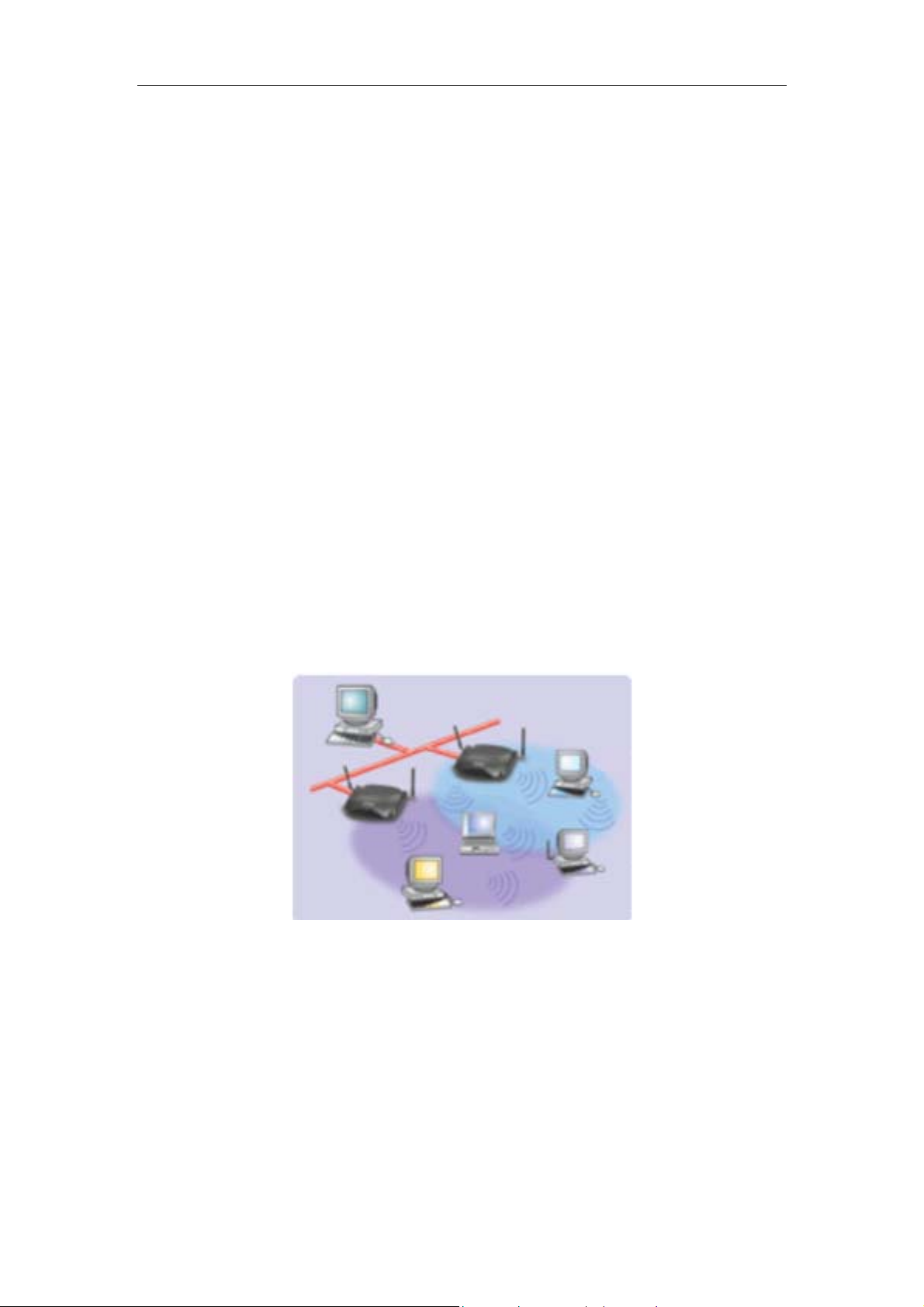
1.2.1 Infrastructure
The WL-3552 provides access to a wired LAN for wireless workstations. An integrated
wireless and wired LAN is called an Infrastructure configuration. A group of WL-3552 PC
users and an Access Point compose a Basic Service Set (BSS). Each WL-3552 PC in a
1
Page 6
WL-3552 User’s Manual
BSS can talk to any computer in the wired LAN infrastructure via the Access Point.
An Infrastructure configuration extends the accessibility of a WL-3552 equipped PC to a
wired LAN, and doubles the effective wireless transmission range for 2 WL-3552 PCs.
Since the Access Point is able to forward data within its BSS, the effective transmission
range in an infrastructure LAN is doubled.
The use of a unique ID in a BSS is essential. All WL-3552 equipped PCs configured without
roaming options in an independent BSS must be configured with a BSS ID corresponding to
the WL-3552 used in the BSS. Check your WL-3552 for its BSS ID or use the Site Survey
function on Configuration Utility program to determine the BSS ID.
The Infrastructure Wireless LAN configuration is appropriate for enterprise-scale wireless
access to a central database, or as a wireless application for mobile users.
Infrastructure mode also supports roaming capabilities for mobile users. More than one
BSS can be configured as an Extended Service Set (ESS). The continuous network allows
users to roam freely within an ESS. All WL-3552 PCs or other IEEE 802.11b compliant
wireless adapter within one ESS must be configured with the same ESS ID and use the
same radio channel.
Before enabling an ESS with roaming capability, choosing a feasible radio channel and
optimum Access Point position is recommended. Proper Access Point positioning combined
with a clear radio signal will greatly enhance performance.
1.2.2 Ad-Hoc
An Ad-Hoc wireless LAN is a group of computers, each equipped with one WL-3552
adapter or other wireless adapters, connected as an independent wireless LAN. Computers
in a specific Ad-Hoc wireless LAN must be configured to share the same radio channel.
Ad-Hoc wireless LAN configurations are appropriate for branch level departments o r SOHO
operations.
2
Page 7

WL-3552 User’s Manual
WL-3552 offers a fast, reliable, cost-effective solution for wireless client access to the
network in applications like these:
1. Remote access to corporate network information
E-mail, file transfer and terminal emulation.
2. Difficult-to-wire environments
Historical or old buildings, asbestos installations, and open area where wiring is
difficult to employ.
3. Frequently changing environments
Retailers, manufacturers and banks who frequently rearrange the workplace and
change location.
4. Temporary LANs for special projects or peak time
Trade shows, exhibitions and construction sites need temporary setup for a short time
period. Retailers, airline and shipping companies need additional workstations for a
peak period. Auditors require workgroups at customer sites.
5. Access to database for mobile workers
Doctors, nurses, retailers, white-collar workers need access to database while being
mobile in the hospital, retail store or office campus.
6. SOHO (Small Office and Home Office) users
SOHO users need easy and quick installation of a small computer network.
7. High security connection
The wireless security network installs quickly and provides the flexibility to reconfigure
easily.
1.3 Specification
Product Wire Free – Wireless LAN 11Mbps PCMCIA Adapter
Model Name WL-3552
Attach Interface PCMCIA Type-II
LED Indicators Act
3
Page 8

WL-3552 User’s Manual
Operating Frequency / Channel 2.412~2.462GHz (FCC, Canada) / 11 Channels
2.412~2.4835GHz (Japan, TELEC) / 14 Channels
2.412~2.472GHz (Euro ETSI) / 13 Channels
RF Modulation Direct Sequence Spread Spectrum (DSSS) Technology
(CCK, DQPSK, DBPSK)
RF Output Power 19dBm
Sensitivity -83dBm (@ PER<8%)
Data Rate 11, 5.5, 2, 1 Mbps with auto-rate fall back
Media Access Protocol CSMA/CA + ACK, IEEE802.11b Compliant
Standard Antenna Built-in dipole antenna
Range Up to 1100 feet outdoor and 350 feet indoor
Working Mode Ad-Hoc, Infrastructure
Power Consumption TX: 3.3V, 500mA
RX: 3.3V, 250mA
Stand by / sleep mode: 3.3V, 20mA
Dimension (mm) 115*55*8 mm
Humidity 0-90%, non-condensing (Operating and storage)
Temperature 0 – 55 deg ree C (Operating), -20~70 degree C(Storage)
Compatibility Windows 98, Me, 2000 and XP
Management Utility or Windows XP built-in management interface
STANDARDS COMPLIANCE
Electromagnetic Compatibility FCC, CE, ETSI 300, 328
1.4 Package Contents
Before installation, please check the items of your package. The package should inclu de the
following items:
One WL-3552
One Quick Installation Guide
One Drivers and User’s Manual CD
If any of the above items are missing, contact your supplier as soon as
possible.
1.5 Minimum System Requirements
Before installation, please check the following requirements with your
equipment.
4
Page 9

WL-3552 User’s Manual
Operating System: MS Windows 98/Me/NT/2000/XP
•
Desktop PC or Notebook with CD-ROM driver
•
ISA to PCMCIA or PCI to PCMCIA controller in case of desktop PC
•
PCMCIA Type or Type slot in case of Notebook.
•
Note: This PCMCIA card support only +3.3V operating voltage. Before plug WL-3552 into your
PCMCIA slot, please ensure it is not work with +5V operation voltage only.
1.6 Safety Precaution
Only use the accessories and connection cables attached with the device package.
Otherwise, the device may not function. If you miss or damage the accessories or
connection cables, please contact your local dealer.
5
Page 10

WL-3552 User’s Manual
Chapter 2 Installation Procedure
Before you proceed with the installation, it is necessary that you have enough information
about the Wireless PCMCIA Card. There are three sections for different OS. Section 2.1
describes how to install the card to Windows 98/ME and Windows 2000. Section 2.2 shows
how to install it to Windows XP and section 2.3 for Windows NT. Please refer to the related
section according to the OS your PC installed.
Note: If you ever install the other Wireless PCMCIA Card before, please uninstall the existed
driver and utility first. If this is the first time to install this device, please refer to the
following steps to complete the installation.
2.1 Windows 98/ME/2000 Installation
The following installation operates under Window 2000. Procedures, however, will be the
same for Window 98/ME.
Note: Do not insert the Wireless PCMCIA Card before completing below process.
STEP I : Driver and Software Installation
A. Insert Drivers and User’s manual CD to your CD drive (suppose D:\). Run “setup.exe”
under “D:\Utility\WL-3552\” directory, or click the “Start” button and choose “Run”. In the
box appears, enter “D:\Utility\WL-3552\ setup.exe” (where “D” is the letter of your
CD-ROM drive). You will see the dialog box as the picture. It will copy some files for
installation
B. When this screen appears, please press “Next” to cont inue.
6
Page 11

WL-3552 User’s Manual
C. Press “Yes” for agrees the License Agreement.
D. You can click “Browse” to specify the Destination Folder that you want to install the utility.
Or you can keep the default setting and click ”Next” to continue.
7
Page 12

WL-3552 User’s Manual
E. You can ch ange the Program Folder name as you wish or use the default name to
continue. Please click “Next” for next step.
F. You can check your install settings in this dialog box. After ensure, please press ”Next”.
8
Page 13

G. Installation will start copy driver and utility to your OS.
WL-3552 User’s Manual
H. After finish driver and utility installation. Please restart your Notebook.
9
Page 14

WL-3552 User’s Manual
STEP II : Hardware Installation
A. You can now safely insert your PCMCIA card. The “ Add new hardware Wizard
“ automatically loads the Driver for your PCMCIA card. As soon as the p rocedure has been
completed it is recommended to reboot your system.
B. In the Windows 2000 installation procedure an extra window appears like below to prompt
“ Digital Signature Not Found “ and ask you whether you would like to continue the
installation. You can safely select “ Yes “.
2.2 Windows XP Installation
Note: Insert the Wireless PCMCIA Card into the your PC or laptop before the installation.
A. Power on the notebook and allow Window XP to load fully. Then insert the WL-3552 to
your notebook. The system will automatic detect the new hardware and prompt you to run
the installation immediately.
10
Page 15

WL-3552 User’s Manual
B. Put Drivers and User’s Manual CD into your CD-ROM and give the path to the executable
folder “Win XP” under the “ Driver -> WL-3552 ” folder. The following InstallShield Wizard
box will show up to guide you how to install properly then click “Next”.
C. The Hardware Installation box will appear, click “Continue Anyway” to start driver
installation.
Click “Finish” to complete the driver installation.
D.
11
Page 16

WL-3552 User’s Manual
After complete the driver installation
E.
To”. Select the “Wireless Network Connection”, and then the “Connect to Wireless
Network” dialog box will appear. Select preferred Wireless Network and click “Connect”
or click “Advanced” for further configuration. If you can’t see your APs in this screen,
please click “Advanced” to change WL-3552 working rate from “Fix 11Mbps” to “Auto”.
That can let you easier to find out all the APs and connect to.
. Click the “Start” button and choose “Connect
2.3 Windows NT 4.0 Installation
Note: Do not insert the Wireless PCMCIA Card before completing below process.
12
Page 17

WL-3552 User’s Manual
Note: In order to be able to install the WL-3552 on to your PC running under Window NT 4.0,
you will need to log on as “Administrator”. Also you will need to have NT Service Pack 4
or above installed.
A. During the installation, you may be prompted to load operating system files from the
Windows installation disk. Please have this disk handy.
B. Since Windows NT 4.0 does not support “ Plug & Play “, you must enable the detection of
PC Cards by the NT with following the procedures.
1. Click Start -> Settings -> Control Panel
2. Double click the “ Devices “ icon
3. Select “ PCMCIA “ from the list and click the “ Startup” button
4. Set the Startup type to “ Boot “ and Click “ OK “
5. Click “ Close “ on the “Devices “ window
C. In order to let the NT know about your new card , you must enable the Network support
by following the next steps:
1. Click Start -> Settings -> Control Panel.
2. Double click the “ Network “ icon.
3. In the “ Network Settings “ dialog box, you will be prompted to install Windows NT
Networking in case no network has been installed yet. Click “ Yes “ and follow the
instruction on the screen. If networking had been installed, you will see a dialog with
several tabs. In the “Adapters” tab click
Setup will determine the type of network adapter card that you are going to use.
D. When prompted to select a driver, locate the driver provided with Drivers and User’s
Manual CD.
E. During the installation, a dialog box appears asking for the I/O Base and IRQ resource
information. In order to find out which values to use, go to Start -> Programs ->
Administrative Tools -> Windows NT Diagnostics -> select the “Resources” tab -> press
the “IRQ” button. Select one free IRQ from the list. Next, press the button “I/O Port” and
choose a 0x20 free I/O space. Add these values into the dialog box. If at any point after
the installation you want to change these values, go to the Control Panel -> Network,
select the Adapters tab, press the Properties button, and fill in the new values.
F. Next dialog box will start copying the files. In case there is a version conflict between one
or more of the files being copied and the files in your system, you should normally keep
the “ Add”. Windows NT Networking
the latest version
G. Finally, when the installation has been completed, you will need to restart your PC.
Note: If the card is not working properly after the restart procedure you should make sure that
your system has free resources since it may show them as being available, although this
may not be true.
13
Page 18

WL-3552 User’s Manual
Chapter 3 Configuration Utility
This chapter describe the utility of the WL-3552, be noted, Windows XP are with built-in
IEEE802.11b interface utility. If the PC runs Windows XP, please direct run the utility from
Windows XP. However, the following information may also help you to know more.
The Configuration Utility is a powerful application that helps you to configure the WL-3552 and
monitor the statistics of the communication process. By Double Click the icon on the system
tray will show you the dialog box as below.
This utility can be used to modify the configuration parameters when the device is active.
Following details the configuration buttons.
NOTE: Click the “Exit” button will exit the configuration application.
3.1 “Status”
Click the “Change” button when set up the necessary parameters, and click “Submit” after
the configuration has been changed.
14
Page 19

Operation mode: Shows the following network modes:
WL-3552 User’s Manual
Infrastructure -- This operation mode requires the presence of an 802.11b Access
Point. All communication is done via the Access Point.
Ad-Hoc -- This mode indicates the 802.11b peer-to-peer operation. All
communication is done from client to client without the use of an Access Point.
Channel: Shows the number of the radio channel used for the networking. Only
Access Points and Ad-Hoc nodes create the BSSID. This parameter is not active in the
infrastructure operation mode.
SSID: Shows the SSID of the BSS that one willing to join.
Tx Rate: Shows the Data Transfer Rate. There are 1 Mbps, 2 Mbps, 5.5 Mbps, 11 Mbps,
and auto mode. If Auto Mode is been selected, the device will select the best transfer
rate automatically.
Power Mgmt Mode: Shows Power Management modes. There are two optional
selections for this mode.
Active -- Adapter will always set in active mode.
Power Save -- Adapter will enter power saving mode when it is idle.
Signal Strength: This bar shows the signal strength level. The higher the blue bar , the
more radio signal been received by the PCMCIA WLAN adapter. This indicator helps to
find the most comfortable antenna/workstation position for quality network operation.
Link quality: The measured Signal Strength level gives the overall Link Quality and
Connection Status.
MAC Address: The MAC Address of the. Unique 48-bit, hard-coded Media Access
Control address known as the station identifier.
15
Page 20

WL-3552 User’s Manual
3.2 “Statistics”
Shows the total amounts of packets been received or transmitted by the adapter.
Data Field: Shows the total amounts of data packets had been successful/unsuccessful
transmitted or received by the adapter..
Management Field: Shows the total amounts of management packets had been
successful/unsuccessful transmitted or received by the adapter.
Rejected Packets Field: Shows the total amounts of rejected packets had been
transmitted or received by the adapter.
3.3 “Site Survey”
This screen shows all the AP or Adapter nearby when operating in Ad-Hoc mode.
Click “ Re-Scan “ to collect the BSSID and Channel information of all the wireless devices
around you.
If one wishes to connect to any device on the list, double-click the selected list and the
16
Page 21

WL-3552 will connect to the selected device automatically.
3.4 “Encryption”
WL-3552 User’s Manual
Additional security can be achieved by using the WEP (Wired Equivalent Privacy) encryption.
WEP encrypts each frame transmitted from the radio using one of the keys entered from this
panel.
There are four 10 Hex digit encryption keys value available for the WEP. One can define the
encryption key values of their own choice.
Enable the WEP (Wired Equivalent Privacy) option in order to activate WEP encryption for
transmissions between the stations and the Access Point. WEP is an authentication algorithm
that protects authorized Wireless LAN users against eavesdropping.
3.5 “Advanced”
17
Page 22

WL-3552 User’s Manual
There are Preamble Type, Fragmentation Threshold, and RTS/CTS Threshold setting
under this mode.
Preamble Type (Short/Long) : Preamble is the first Suffield of PPDU, which is the
appropriate frame format for transmission to PHY (Physical layer). There are two options,
Short Preamble and Long Preamble. The Short Preamble option improves throughput
performance.
Fragmentation threshold: The size at which packets will be fragmented. Choose a
setting within a range from 256 to 2346 bytes.
RTS Threshold: Minimum packet size to require an RTS (Request To Send). For
packets smaller than this threshold, an RTS is not sent and the packet is transmitted
directly to the WLAN. This is the option for the RTS Threshold activation.
3.6 “Version”
It shows the current Driver, Firmware, and Application Version of this device.
18
Page 23

WL-3552 User’s Manual
Appendix
This section provides some concepts of wireless LAN.
What is the IEEE 802.11b standard?
The IEEE 802.11b Wireless LAN standards subcommittee, which is formulating a
standard for the industry. The objective is to enable wireless LAN hardware from
different manufactures to communicate.
What IEEE 802.11 feature are supported?
The product supports the following IEEE 802.11 functions:
CSMA/CA plus Acknowledge protocol
Multi-Channel Roaming
Automatic Rate Selection
RTS/CTS feature
Fragmentation
Power Management
What is Ad-hoc?
An Ad-hoc integrated wireless LAN is a group of computers, each with a WLAN adapte r,
Connected as an independent wireless LAN. Ad-hoc wireless LAN is applicable at a
departmental scale for a branch or SOHO operation.
What is Infrastructure?
An integrated wireless and wired LAN is called an Infrastructure configuration.
Infrastructure is applicable to enterprise scale for wireless access to central database,
or wireless application for mobile workers.
What is BSS ID?
A specific Ad-hoc LAN is called a Basic Service Set (BSS). Computers in a BSS must
be configured with the same BSS ID.
What is WEP?
WEP is Wired Equivalent Privacy, a data privacy mechanism based on a 64/128 bit
shared key algorithm, as described in the IEEE 802.11b standard.
Can Wireless products support printer sharing?
Wireless products perform the same function as LAN products. Therefore, Wireless
products can work with Netware, Windows NT/2000/XP, or other LAN operating systems
to support printer or file sharing.
Would the information be intercepted while transmitting on air?
WLAN features two-fold protection in security. On the hardware side, as with Direct
19
Page 24

WL-3552 User’s Manual
Sequence Spread Spectrum technology, it has the inherent security feature of
scrambling. On the software side, WLAN series offer the encryption function (WEP) to
enhance security and Access Control. Users can set it up depending upon their needs.
What is DSSS? What is FHSS? And what are their differences?
Frequency-hopping-spread-spectrum (FHSS) uses a narrowband carrier that changes
frequency in a pattern that is known to both transmitter and receiver. Properly
synchronized, the net effect is to maintain a single logical channel. To an unintended
receiver, FHSS appears to be short-duration impulse noise. Direct-sequence
spread-spectrum (DSSS) generates a redundant bit pattern for each bit to be
transmitted. This bit pattern is called a chip (or chipping code). The longer the chip, the
greater the probability that the original data can be recovered. Even if one or more bits
in the chip are damaged during transmission, statistical techniques embedded in the
radio can recover the original data without-the need for retransmission. To an
unintended receiver, DSSS appears as low power wideband noise and is rejected
(ignored) by most narrowband receivers.
What is Spread Spectrum?
Spread Spectrum technology is a wideband radio frequency technique developed by
the military for use in reliable, secure, mission-critical communication systems. It is
designed to trade off bandwidth efficiency for reliability, integrity, and security. In other
words, more bandwidth is consumed than in the case of narrowband transmission, but
the trade off produces a signal that is, in effect, louder and thus easier to detect,
provided that the receiver knows the parameters of the spread-spectrum signal being
broadcast. If a receiver is not tuned to the right frequency, a spread –spectrum signal
looks like background noise. There are two main alternatives, Direct Sequence Spread
Spectrum (DSSS) and Frequency Hopping Spread Spectrum (FHSS).
20
 Loading...