

Page 1

24-Port 10/100Mbps with PoE
+ 2G TP/SFP Combo
Managed Ethernet Switch
WGSW-2620PV
User's Manual
Page 2

Trademarks
Copyright © PLANET Technology Corp. 2005.
Contents subject to which revision without prior notice.
PLANET is a registered trademark of PLANET Technology Corp. All other trademarks belong to their
respective owners.
Disclaimer
PLANET Technology does not warrant that the hardware will work properly in all environments and
applications, and makes no warranty and representation, either implied or expressed, with respect to the
quality, performance, merchantability, or fitness for a particular purpose.
PLANET has made every effort to ensure that this User's Manual is accurate; PLANET disclaims liability
for any inaccuracies or omissions that may have occurred.
Information in this User's Manual is subject to change without notice and does not represent a
commitment on the part of PLANET. PLANET assumes no responsibility for any inaccuracies that may be
contained in this User's Manual. PLANET makes no commitment to update or keep current the
information in this User's Manual, and reserves the right to make improvements to this User's Manual
and/or to the products described in this User's Manual, at any time without notice.
If you find information in this manual that is incorrect, misleading, or incomplete, we would appreciate
your comments and suggestions.
FCC Warning
This equipment has been tested and found to comply with the limits for a Class A digital device, pursuant
to Part 15 of the FCC Rules. These limits are designed to provide reasonable protection against harmful
interference when the equipment is operated in a commercial environment. This equipment generates,
uses, and can radiate radio frequency energy and, if not installed and used in accordance with the
Instruction manual, may cause harmful interference to radio communications. Operation of this
equipment in a residential area is likely to cause harmful interference in which case the user will be
required to correct the interference at whose own expense.
CE Mark Warning
This is a Class A product. In a domestic environment, this product may cause radio interference, in which
case the user may be required to take adequate measures.
Revision
PLANET Fast Ethernet Switch User's Manual
FOR MODELS: WGSW-2620PV
Part No. 2081-A92300-000
Page 3

Table of Contents
1. INTRODUCTION................................................................................................................... 5
1.1 Packet Contents.............................................................................................................. 5
1.2 How to Use This Manual ................................................................................................. 5
1.3 Product Feature............................................................................................................... 5
1.4 Product Specification....................................................................................................... 6
2. INSTALLATION..................................................................................................................... 8
2.1 Product Description......................................................................................................... 8
2.2 Install the Switch ............................................................................................................. 9
3. CONSOLE MANAGEMENT................................................................................................ 12
3.1 Connecting to the Switch .............................................................................................. 12
3.3 CLI Management........................................................................................................... 13
3.4 Menu Management ....................................................................................................... 46
4. WEB-BASED MANAGEMENT........................................................................................... 92
4.1 About Web-based Management.................................................................................... 92
4.2 Preparing for Web Management................................................................................... 92
4.3 Online Help.................................................................................................................... 92
4.4 System Login................................................................................................................. 93
4.5 Port status ..................................................................................................................... 93
4.6 Port Statistics................................................................................................................. 94
4.7 Administrator ................................................................................................................. 95
4.8 TFTP Update Firmware............................................................................................... 122
4.9 Configuration Backup.................................................................................................. 123
4.10 Factory Default.......................................................................................................... 124
4.11 System Reboot .......................................................................................................... 124
4.12 UPS Status ................................................................................................................ 125
4.13 POE Status................................................................................................................ 126
Page 4

5. TROUBLESHOOTING...................................................................................................... 128
5.1 Incorrect connections.................................................................................................. 128
5.2 Diagnosing LED Indicators.......................................................................................... 128
5.3 Diagnosing POE problems.......................................................................................... 129
6. Appendix .......................................................................................................................... 130
6.1 Console Port Pin Assignments.................................................................................... 130
6.2 100BASE-TX/10BASE-T Pin Assignments ................................................................. 131
Page 5

1. INTRODUCTION
1.1 Packet Contents
Check the contents of your package for following parts:
▫ Fast Ethernet PoE Switch x1
▫ CD-ROM user's manual x1
▫ Quick installation guide x1
▫ 19" rack mounting kit x1
▫ Power cord x1
▫ Rubber feet x 4
If any of these are missing or damaged, please contact your dealer immediately, if possible, retain the
carton including the original packing material, and use them against to repack the product in case there is
a need to return it to us for repair.
1.2 How to Use This Manual
This User Manual is structured as follows:
Chapter 2, Installation
The chapter explains the functions of the Switch and how to physically install the Switch.
Chapter 3, CONSOLE MANAGEMENT
The chapter explains how to manage the switch by Console interface.
Chapter 4, WEB-BASED MANAGEMENT
The chapter explains how to manage the switch by Web interface.
Chapter 5, TROUBLE SHOOTING
The chapter explains how to trouble shooting of the Switch.
Chapter 6, APPENDIX
The chapter contains cable information of the Switch.
In the following section, terms "SWITCH" with upper case denotes the WGSW-2620PV Ethernet switch.
Terms with lower case "switch" means any Ethernet switches.
1.3 Product Feature
▫ 24-Port 10/100Mbps TP ports with PoE injector
▫ 2G TP/SFP combo interface
▫ Complies to IEEE802.3 10BASE-T, 802.3u 100BASE-TX/FX, 802.3ab 1000BASE-T, 802.3z
Page 6

Gigabit fiber, 802.3af power over Ethernet
▫ High back-plane bandwidth 8.8Gbps
▫ IGMP snooping and IGMP Query mode for Multi-media application
▫ Port mirror and bandwidth control
▫ Supports GVRP function
▫ End point insert mode remote power feeding
▫ Provides extra DC 48V input with redundant function and management power status through
RS-232 port
▫ On line extra power supply testing through RS-232 port
▫ Management by Web/SNMP/Telnet/Console
▫ Port Based VLAN /802.1Q Tag VLAN
▫ IEEE802.3x Flow control – flow control for full duplex, back pressure for half duplex
▫ IEEE802.3ad Port trunk with LACP
▫ Spanning tree protocol IEEE 802.1d/802.1w
▫ IEEE 802.1p class of service
▫ IEEE 802.1x user authentication, TACACS+
▫ Broadcast storm filter
▫ DHCP client/DHCP relay
▫ Support command line interface management
▫ System event log support
1.4 Product Specification
Model WGSW-2620PV
Network Connector 24-port RJ-45 for 10/100TX
RJ-45 Pin assignment and polarity: 1/2:RX signal and -48V DC; 3/6:TX
signal and +48V DC
Gigabit Connector 2 TP + 2 mini-GBIC
RS-232 connector One RS-232 DB-9 female connector for switch management and 2
RS-232 DB-9 male connectors on rear side for DC power supply and
UPS management.
Switch architecture Store and forward switch architecture. Back-plan up to 8.8Gbps
MAC address 8K MAC address table with Auto learning function
Memory 3Mbits for packet buffer
LED System Power
10/100TX RJ-45 Port: Link/Active, Full-duplex, Power Forwarding
Gigabit Fiber (module): Link/ Activity
Gigabit Copper (module): Link/Activity, Full duplex/collision, 1000Mbps,
100Mbps
Page 7

100FX module (module)): Link/Activity, Full duplex
Remote power feeding End-point insert type and compatible with IEEE802.3af
Per port feeding power: 15.4Watts (maximum)
Power Embedded AC power supply: AC 90~240V, 2.5A, 50/60Hz, 200W
Extra power input: DC48V
Operating environment 0℃~40℃, 10%~95%RH
Storage environment -40℃~70℃, 95% RH
Dimension 440mm(W) x 280mm(D) x 44mm(H)
EMI FCC Class A, CE
Safety UL, cUL, CE/EN60950
Standard Compliance IEEE802.3 10BASE-T
IEEE802.3u 100BASE-TX/100BASE-FX
IEEE802.3z Gigabit SX/LX
IEE802.3ab Gigabit 1000T
IEEE802.3x Flow Control and Back pressure
IEEE802.3ad Port trunk with LACP
IEEE802.1d Spanning tree protocol
IIEEE802.1w Rapid spanning tree protocol
IEEE802.1p Class of service
IEEE802.1Q VLAN Tagging
IEEE 802.1x user authentication
IEEE802.3af Power over Ethernet
Page 8

2. INSTALLATION
This section describes the functionalities of the Switch's components and guides how to install it on the
desktop or shelf. Basic knowledge of networking is assumed. Please read this chapter completely before
continuing.
2.1 Product Description
The PLANET WGSW-2620PV PoE Switch features Power-over-Ethernet (PoE), which optimizes the
installation and power management of network devices such as wireless access points (AP), Voice over
IP (VoIP) phones, and security video cameras. Power-over-Ethernet (IEEE 802.3af) capabilities reduce
installation costs for many new network productivity devices. It frees the wireless AP deployment from
restrictions due to power outlet locations. Power and data switching are integrated into one unit and
delivered over a single cable, eliminating costs for additional AC wiring and reducing installation time.
With twenty-four 10/100Mbps RJ-45 ports, two GbE copper ports and two shared SFP / copper GbE
interface, PLANET WGSW-2620PV boasts a high performance switch architecture that is capable of
providing non-blocking switch fabric and wire-speed throughput as high as 8.8Gbps. Its four built-in GbE
uplink ports also offer incredible extensibility, flexibility and connectivity to the Core switch or Servers.
The IEEE 802 standard-based firmware provides a rich set of features and ensures interoperability with
equipment from other vendors. Additionally, the firmware includes advanced features such as IGMP
snooping, broadcast storm control, and MAC address filtering, to enhance security and bandwidth
utilization.
2.1.1 Product Overview
With its built-in web-based management, the PLANET WGSW-2620PV offers an easy-to-use,
platform-independent management and configuration facility. The PLANET WGSW-2620PV supports
standard Simple Network Management Protocol (SNMP) and can be managed via any standard-based
management software. For text-based management, the WGSW-2620 can also be accessed via Telnet
and the console port.
An optional power supply, the USP-400, can be chosen as UPS or redundant power for WGSW-2620PV.
The WGSW-2620 can take electrical power from the AC outlet, the UPS-400 and both for redundant. The
UPS-400 supports 400 watts of electrical power, once the AC power shut off, the UPS-400 then take over
as the UPS power supply for WGSW-2620PV and keep the switch and the connected powered devices
working.
Page 9
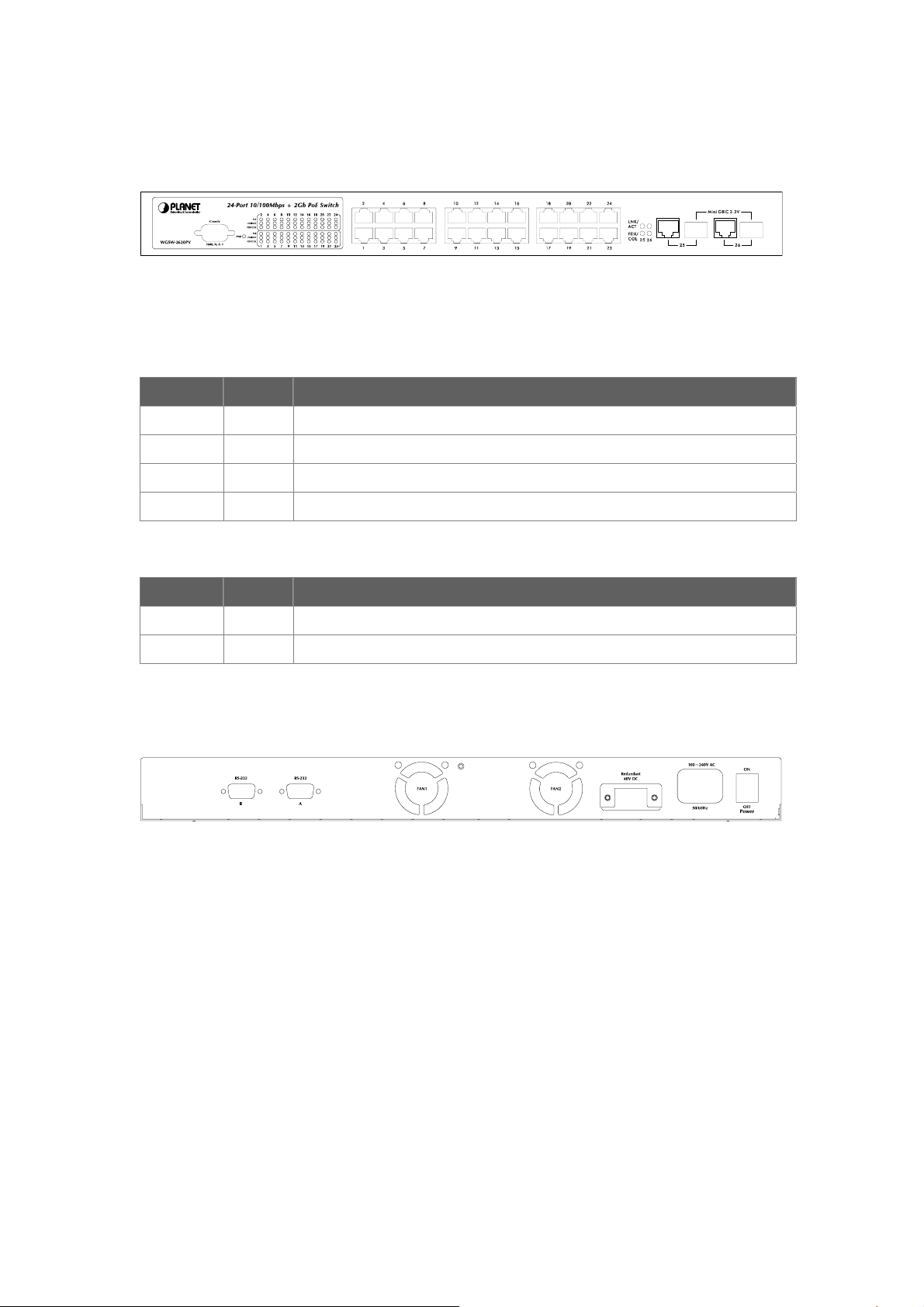
2.1.2 Switch Front Panel
Figure 2-1 shows the front panel of the switch.
Figure 2-1 WGSW-2620PV front panel.
2.1.3 LED Indications
Network/PoE:
LED Color Function
PWR Green Lights to indicate that the Switch is powered on.
PoE Green Lights to indicate the port is providing 48VDC in-line power.
LNK/ACT Green Lights to indicate the link through that port is successfully established.
FDX/COL Green Blink to indicate that the switch is actively sending or receiving data over that port.
Gigabit:
LED Color Function
LNK/ACT Green Lights to indicate the link through that port is successfully established.
FDX/COL Green Blink to indicate that the switch is actively sending or receiving data over that port.
2.1.4 Switch Rear Panel
Figure 2-2 shows the rear panel of the switch
Figure 2-2 WGSW-2620PV rear panel.
Power Notice:
1. The device is a power-required device, it means, it will not work till it is powered. If your networks
should active all the time, please consider using UPS (Uninterrupted Power Supply) for your device.
It will prevent you from network data loss or network downtime.
2. In some area, installing a surge suppression device may also help to protect your switch from being
damaged by unregulated surge or current to the Switch or the power adapter.
2.2 Install the Switch
This section describes how to install the Ethernet Switch and make connections to it. Please read the
following topics and perform the procedures in the order being presented.
Page 10

2.2.1 Desktop Installation
To install the Switch on desktop or shelf, please follows these steps:
Step1: Attach the rubber feet to the recessed areas on the bottom of the switch.
Step2: Place the switch on the desktop or the shelf near an AC power source.
Step3: Keep enough ventilation space between the switch and the surrounding objects.
"Note: When choosing a location, please keep in mind the environmental restrictions discussed in
Chapter 1, Section 4, in Specification.
Step4: Connect the Switch to network devices.
A. Connect one end of a standard network cable to the 10/100/1000 RJ-45 ports on the front of the
Switch
B. Connect the other end of the cable to the network devices such as printer servers, workstations
or routers…etc.
"Note: Connection to the Switch requires UTP Category 5 network cabling with RJ-45 tips. For more
information, please see the Cabling Specification in Appendix A.
Step5: Supply power to the switch.
A. Connect one end of the power cable to the switch.
B. Connect the power plug of the power cable to a standard wall outlet.
When the switch receives power, the Power LED should remain solid Green.
2.2.2 Rack Mounting
To install the switch in a 19-inch standard rack, please follows the instructions described below.
Step1: Place the switch on a hard flat surface, with the front panel positioned towards the front side.
Step2: Attach the rack-mount bracket to each side of the switch with supplied screws attached to the
package.
Figure 2-5 shows how to attach brackets to one side of the switch.
Figure 2-5 Attach brackets to the switch.
Caution:
You must use the screws supplied with the mounting brackets. Damage caused to the parts by using
incorrect screws would invalidate the warranty.
Step3: Secure the brackets tightly.
Page 11
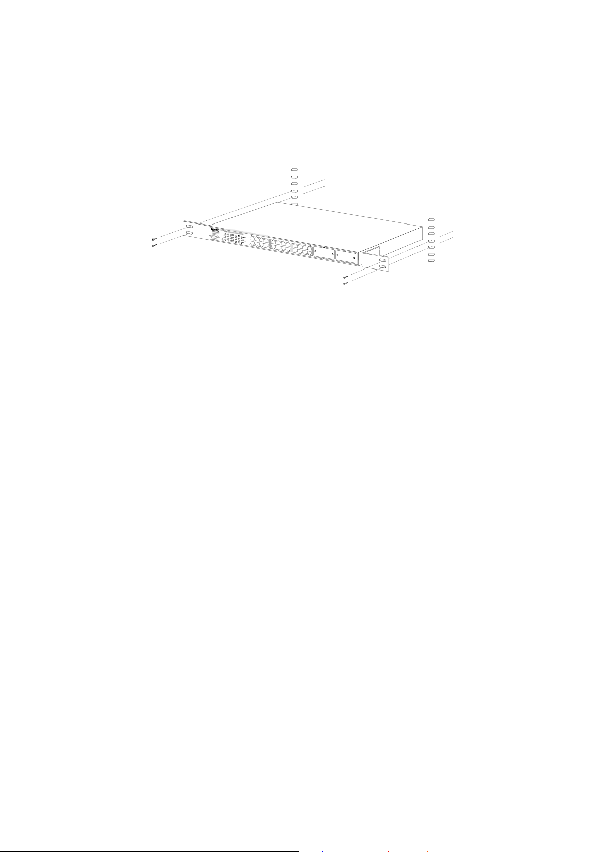
Step4: Follow the same steps to attach the second bracket to the opposite side.
Step5: After the brackets are attached to the Switch, use suitable screws to securely attach the brackets
to the rack, as shown in Figure 2-6
Figure 2-6 Mounting the Switch in a Rack
Step6: Proceeds with the steps 4 and steps 5 of session 2.2.1 Desktop Installation to connect the
network cabling and supply power to the switch.
Page 12
3. CONSOLE MANAGEMENT
3.1 Connecting to the Switch
The console port is a female DB-9 connector that enables a connection to a PC or terminal for monitoring
and configuring the Switch. Use the supplied RS-232 cable with a male DB-9 connector to connect a
terminal or PC to the Console port. The Console configuration (out of band) allows you to set Switch for
remote terminal as if the console terminal were directly connected to it.
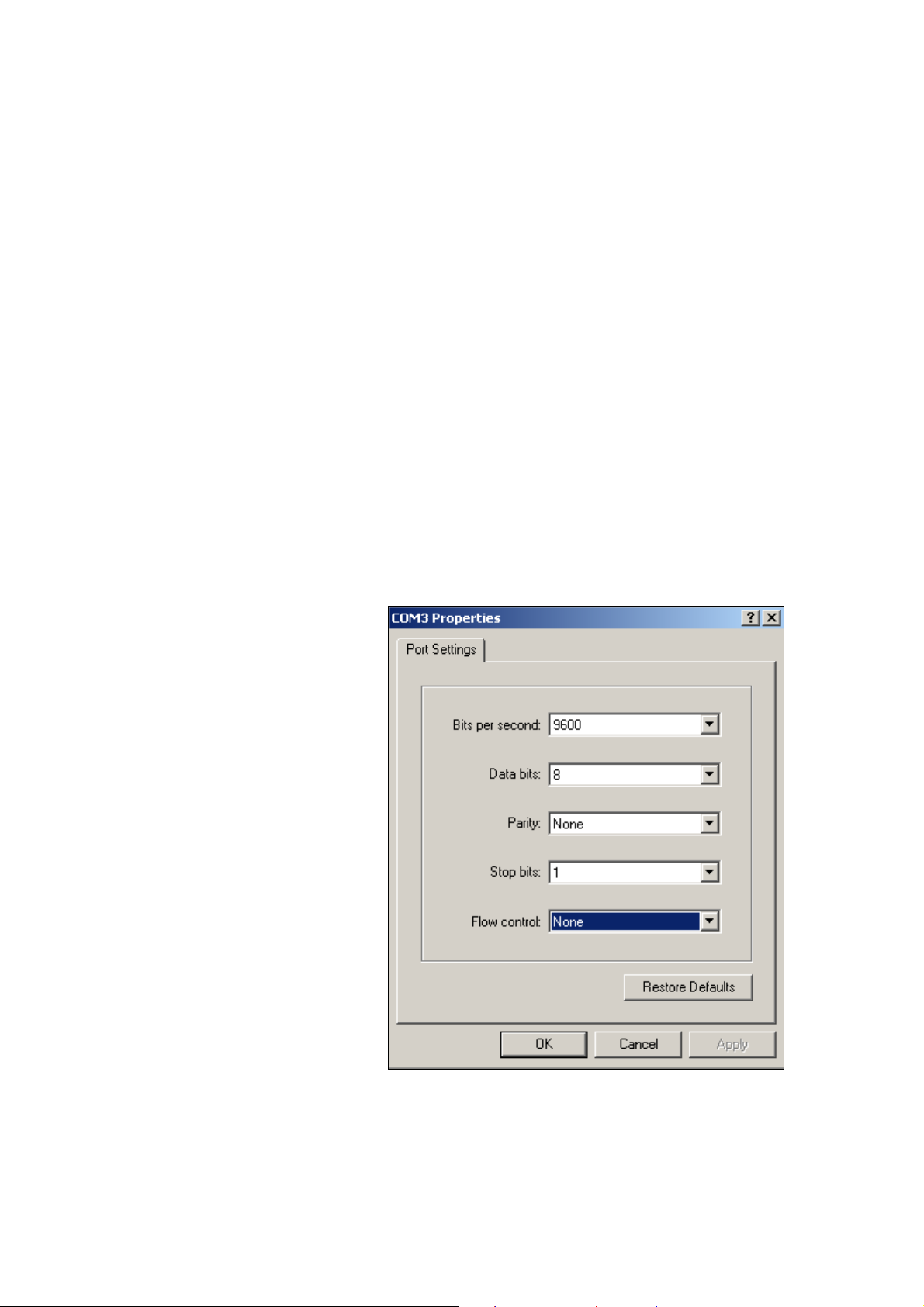
3.2 Login in the Console Interface
When the connection between Switch and PC is ready, turn on the PC and run a terminal emulation
program or Hyper Terminal and configure its communication parameters to match the following default
characteristics of the console port:
Baud Rate: 9600 bps
Data Bits: 8
Parity: none
Stop Bit: 1
Flow control: None
After finished the parameter settings, click “OK“. When the blank screen shows up, press Enter key to
The settings of communication parameters
Page 13
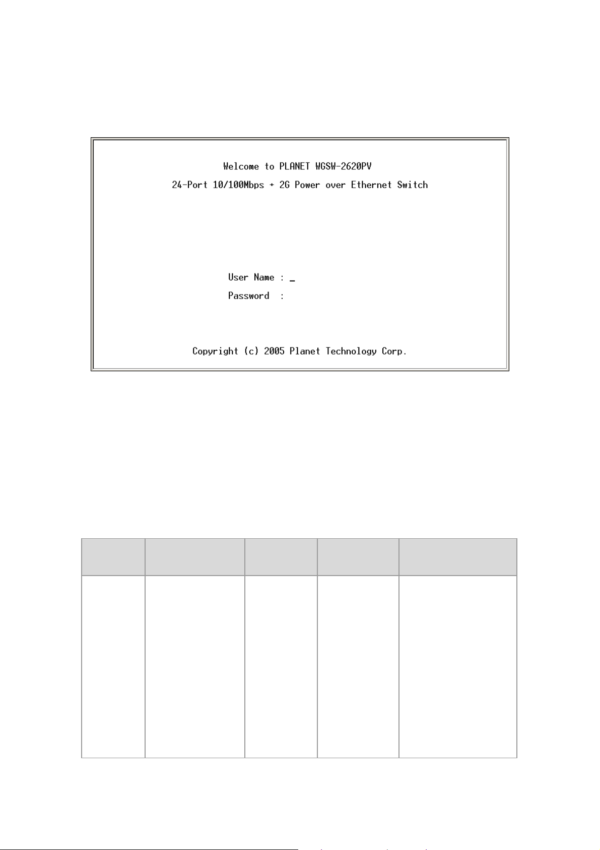
bring out the login prompt. Key in the “admin“(default value) for the both User name and Password (use
Enter key to switch), then press Enter key and the Main Menu of console management appears. Please
see below figure for login screen.
Console login screen
3.3 CLI Management
The system supports two types of console management - CLI command and Menu selection. After you
login to the system, you will see a command prompt. To enter CLI management interface, enter "enable"
command. The following tables list the CLI commands and description.
3.3.1 Commands Level
Modes Access Method Prompt Exit Method About This Mode
The user commands
available at the user level
are a subset of those
available at the privileged
level.
User EXEC
Begin a session with
your switch.
switch>
Enter logout or
quit.
Use this mode to
• Perform basic tests.
• Display system
Page 14

information.
The privileged command
is advance mode
Privileged
EXEC
Global
Configuratio
n
VLAN
database
Enter the enable
command while in
user EXEC mode.
Enter the configure
command while in
privileged EXEC
mode.
Enter the vlan
database command
while in privileged
EXEC mode.
switch#
switch
(config)#
switch (vlan)#
Enter disable to
exit.
To exit to
privileged EXEC
mode, enter exit
or end
To exit to user
EXEC mode,
enter exit.
Privileged this mode to
• Display advance
function status
• Save configures
Use this mode to
configure parameters that
apply to your switch as a
whole.
Use this mode to
configure VLAN-specific
parameters.
Interface
configuratio
n
UPS
POE
Enter the interface
command (with a
specific interface)
while in global
configuration mode
Enter the ups
command while in
privileged EXEC
mode.
Enter the poe
command while in
privileged EXEC
mode.
switch
(config-if)#
switch(ups)#
switch(poe)#
To exit to global
configuration
mode, enter exit.
To exist to
privileged EXEC
mode, or end.
To exit to
privileged EXEC
mode, enter exit
To exit to
privileged EXEC
mode, enter exit
Use this mode to
configure parameters for
the switch and Ethernet
ports.
Use this mode to UPS
parameters for the
switch.
Use this mode to POE
parameters for the switch.
Page 15

3.3.2 Commands Set List
3.3.2.1 System Commands Set
Commands
system name
[systemname]
system
location
[system
location]
system
description
[systemdescrip
tion]
Command
Level
Global
configuration
mode
Global
configuration
mode
Global
configuration
mode
Description
Set switch system name
string
Set switch system location
string
Set switch system
description string
Defaults
Example
Switch (config)#
system name xxx
Switch (config)#
system location xxx
Switch (config)#
system description
xxx
system contact
[systemcontact
]
ip address
[ip-address]
[subnet-mask ]
[ gateway]
reload
Global
configuration
mode
Global
configuration
mode
Global
configuration
mode
Set switch system contact
window string
Use the ip address interface
configuration command to
set an IP address for a
switch. Use the no form of
this command to remove an
IP address or to disable IP
processing.
Halt and perform a cold
restart
Switch (config)#
system contact xxx
Switch (config)# ip
address
192.168.0.100
255.255.255.0
192.168.0.254
Switch (config)#
reload
Page 16

default
Global
configuration
mode
Restore to default
Switch (config)#
default
username
[user-name]
password
[password]
show system
info
Global
Changes a login username.
configuration
(maximum 10 words)
mode
Global
Specifies a password
configuration
(maximum 10 words)
mode
User EXEC Show system information
Switch (config)#
username xxxxxx
Switch (config)#
password xxxxxx
Switch> show
system info
Name: switch1
location: lab
Description: layer2
switch
show ip
Privileged
EXEC
Show ip information
Contact: somewhere
Serial NO: 1.00
Switch# show ip
address
ip: 192.168.0.100
Address subnet:
255.255.255.0
Address gateway:
192.168.0.254
Page 17

Switch# show
show
accounting
show version
Privileged
EXEC
User EXEC
Show username &
password
Use the show version user
EXEC command to display
version information for the
hardware and firmware.
accounting
Username: admin
Password: admin
Switch> show
version
Firmware version:
1.0
Hardware version:
3.0
Kernel version: 1.10
Switch (config)#
show terminal
Privileged
show terminal
EXEC
3.3.2.2 Port Commands Set
Command
Commands
Level
interface
Interface
[FastEthernet
configuratio
/module Ethernet]
n mode
[slot id] [id]
Use the show terminal
command to display
console information for the
switch
Description Defaults Example
Use the fast Ethernet
interface configuration
command
Baud rate (bits/sec):
9600
Data Bits: 8
Parity Check: none
Stop Bits: 1
Flow Control: none
Switch (config)#
interface
fastEthernet 0/1
Page 18

Use the module Ethernet
interface configuration
command
Switch (config)#
interface
moduleEthernet
1/1
duplex [full | half|
auto]
speed
[10 | 100 | 1000 |
auto]
Interface
configuratio
n mode
Interface
configuratio
n mode
Use the duplex
configuration command
to specify the duplex
mode of operation for
Fast
Ethernet.
Use the duplex
configuration command
to specify the duplex
mode of operation for
module Ethernet.
Use the speed
configuration command
to specify the speed
mode of operation for
Fast Ethernet.
Auto
Auto
Auto
Switch (config)#
interface
fastEthernet 0/1
Switch (config-if)#
duplex full
Switch (config)#
interface
moduleEthernet
1/1
Switch (config-if)#
duplex full
Switch (config)#
interface
fastEthernet 0/1
Switch (config-if)#
speed 10
speed [10| 100 |
1000 | auto]
Interface
configuratio
n mode
Use the speed
configuration command
to specify the speed
mode of operation for
module
Ethernet.
(The 100Base-FX
module only supported
Switch (config)#
interface
fastEthernet 1/2
Switch (config-if)#
speed 1000
Page 19

for speed 100)
(The 1000Base-FX
module only supported
for speed 1000 & auto)
Use the flow control
flowcontrol on or
no flowcontrol
security on or no
security
Interface
configuratio
n mode
Interface
configuratio
n mode
configuration command
on Ethernet ports to
control traffic rates during
congestion.
Use the no form of this
command to disable
security on the port.
Use the security
configuration command
on Ethernet ports.
Use the no form of this
command to disable
security on the port.
On
Disable
Switch (config)#
interface
fastEthernet 0/1
Switch (config-if)#
flowcontrol on
Switch (config)#
interface
fastEthernet 0/1
Switch (config-if)#
security on
priority on [hi | low]
or no priority
Interface
configuratio
n mode
Use the priority
configuration command
on Ethernet ports.
Use the no form of this
command to disable
security on the port.
Disable
Switch (config)#
interface
fastEthernet 0/1
Switch (config-if)#
priority on hi
Page 20

Bandwidth [in | out]
[value]
State [Enable |
Disable]
Interface
configuratio
n mode
Interface
configuratio
n mode
Set bandwidth in or out
rate. The value rage is
(0~999), and zero of the
value is disable
(The module can’t be
setting)
Use the state interface
configuration command
to specify the state mode
of operation for Ethernet
ports. Use the disable
form of this command to
disable the port.
Disable
Enable
Switch (config)#
interface
fastEthernet 0/1
Switch (config-if)#
bandwidth hi 50
Switch (config)#
interface
fastEthernet 0/1
Switch (config-if)#
state disable
show interface
configuration
show interface
status
Interface
configuratio
n mode
Interface
configuratio
n mode
show interface
configuration status
show interface actual
status
Switch (config)#
interface
fastEthernet 0/1
Switch (config-if)#
show interface
configuration
Switch (config)#
interface
fastEthernet 0/1
Switch (config-if)#
show interface
status
Page 21

show interface
accounting
Interface
configuratio
n mode
show interface statistic
counter
Switch (config)#
interface
fastEthernet 0/1
Switch (config-if)#
show interface
accounting
Switch (config)#
Interface
show bandwidth
configuratio
n mode
3.3.2.3 Trunk Commands Set
Commands
show group
[group-ID]
Command
Level
Privileged
EXEC
mode
interface
Display the bandwidth of
the values
Description Defaults Example
Display trunk group
information. If there is no
group-number in put,
display all trunk groups.
fastEthernet 0/1
Switch (config-if)#
show bandwidth
Switch # show
group 1
Group Trunk.1:
Ports: 02 03 04
Priority: 0001
Lacp: Enable
Work ports: 0
Page 22

LACP:
port group
[group-number]
[port-list] lacp [on |
off] workp [work
ports]
no port group
[group-number]
lacp [on | off] workp
[work ports]
Global
configuratio
n mode
Add trunking group.
Use the no form of this
command to delete
trunking group.
Switch (config)#
port group 1 1-4
lacp on workp 2
Disable
Trunk without
LACP:
Switch (config)#
port group 1 1-4
lacp off workp 4
Switch (config)#
port group 3
activityport 2-4
port group
Global
[group-number]
activityport
[port-list]
configuratio
n mode
3.3.2.4 VLAN Commands Set
Commands
Vlan datatbase
Command
Level
Privileged
EXEC
mode
Set trunking group port
active
Description Defaults Example
To enter the VLAN
configuration interface
Trunk.1 Lacp:
Enable
Check OK!
NEW: 2 4
Update finished!!
Switch# vlan
database
Switch(vlan)#
Page 23

vlanmode [disable|
portbase| 802.1q |
gvrp]
Port Base VLAN
VLAN
database
mode
To set switch VLAN
mode .Use the no form of
this command to restore
to default.
Disable
Switch (vlan)#
vlanmode 802.1q
vlan [Group Name]
grpid [Group ID]
port [Port Number]
no vlan Group
Name] [Group ID]
show vlan
[GroupName]
[GroupID] or show
vlan
vlan [Group name]
add [port Number]
[tagged | untagged]
VLAN
database
mode
VLAN
database
mode
VLAN
database
mode
VLAN
database
mode
Add new Port Base VLAN
Delete port base VLAN group
Show VLAN of Group Name
or Group ID information
Set the port of some port
group tagged or untagged
Switch
(vlan)# vlan
v2 grpid 2
port 1-4
Switch
(vlan)# no
vlan v2 2
Switch
(vlan)#
Show vlan
v2 2
Switch
(vlan)# vlan
v2 add 5
vlan [Group name]
delete [port
Number]
vlan [Group name]
vlanid [Vlan ID] port
[port Number] tag
[port Number]
VLAN
database
mode
802.1Q | 802.1Q with GVRP VLAN mode
VLAN
database
mode
Remove the port from it’s port
group.
Add new 802.1Q VLAN
[VLAN name]:
VLAN name
[VLAN ID]: 1 ~ 4094
Switch
(vlan)# vlan
v2 delete 5
Switch(vlan
)# vlan v2
vlanid 2
port 1-4
tag 2-4
Page 24

[port ID]:
port members 1~9
vlan [group name]
delete [port ID]
no vlan
[Group name] or
[VLAN ID]
VLAN
database
mode
VLAN
database
mode
Remove the port from its port
group.
Delete 802.1Q VLAN group
Add protocol vlan
[VLAN name]: vlan group
name
Switch(vlan
)# vlan v2
delete 5
Switch
(vlan)# no
vlan v2
Switch
(vlan)# no
vlan v2 2
Switch(vlan
)# vlan
protocol
v3 ip
vlanid 2
vlan protocol
[VLAN name]
[protocol value]
vlanid [VLAN ID]
port [port ID] tag
[port ID]
VLAN
database
mode
VIA 6510 serial of values
[protocol value]:
IP-ip
ARP-arp
Appletalk-app
Appletalk_AARP-app_arp
Novell_IPX-ipx
Banyan_vines-banyan
Decent_mop-decent_mop
Decent_dpr-decent_dpr
Decent_LAT-decent_lat
Decent_LAVC-decent_lavc
port 5-8
tag 6,8
Switch(vlan
)# vlan
protocol
v3 arp
vlanid 2
port 5-8
tag 6,8
Switch(vlan
)# vlan
protocol
v3 banyan
vlanid 2
Page 25

IBM SNA-ibm
port 5-8
X.75 internet-x75
X.25 Layer3-x25
NetBIOS-netbios
IOS Network Layer PDU
-IOS
Novell_IPX(raw Ethernet)
-ipx_raw
Spanning Tree Protocol
BPDU-stp
Null SAP-sap
tag 6,8
VIA 6526 serial of values
IP-ip
ARP-arp
Appletalk-app
Appletalk_AARP-app_arp
Novell_IPX-ipx
Banyan_vines-banyan_c4
Banyan_vines-banyan_c5
Banyan_vines-banyan_ad
Decent_mop_01-decent_01
Decent_mop_02-decent_02
Decent_dpr-decent_dpr
Decent_LAT-decent_lat
Decent_LAVC-decent_lavc
Page 26

IBM SNA-ibm
X.75 internet-x75
X.25 Layer3-x25
[VLAN ID]: 1 ~ 4094
[port ID]:
port ID 1~9(1~26)
Set VLAN ID range
[1~255] range 0
[256~511] range 1
[512~767] range 2
vlanidrange
[VLANidrange]
VLAN
database
mode
[768~1023] range 3
[1024~1279] range 4
[1280~1535] range 5
[1536~1791] range 6
[1792~2047] range 7
[2048~2303] range 8
[2304~2559] range 9
[2560~2815] range 10
[2816~3071] range 11
[3072~3327] range 12
[3328~3583] range 13
Switch
(vlan)#
vlanidrang
e 2
OLD: 0
NEW: 2
[3584~3839] range 14
[3840~4094] range 15
Page 27

VLAN protocol
[Groupname] add
[portNumber]
[tagged | untagged]
VLAN
database
mode
Set the port of some port
group tagged or untagged
Switch
(vlan)# vlan
protocol
v2 add 5
tagged
VLAN protocol
[Groupname] delete
[portNumber]
show vlan
[Groupname]
[GroupID] or show
vlan
show vlan protocol
VLAN
database
mode
VLAN
database
mode
VLAN
database
mode
Remove the port from its port
group.
Show VLAN of Group Name
or VLAN ID information
vlanid: 1 ~ 4094
show protocol vlan
Protocol
ip
ipx
netbios
Switch
(vlan)# vlan
protocol
v2 delete 5
Switch
(vlan)#
show vlan
v2 2
Switch
(vlan)#
show vlan
protocol
port [port ID] pvid
[port VID]
ingressfilter1 [on |
off] ingressfilter2
[on | off]
show port [port ID]
VLAN
database
mode
VLAN
database
mode
Set Port PVID and Ingress
Filter Rules1 & Ingress Filter
Rules2
show Port PVID and Ingress
Filter Rules1 & Ingress Filter
Rules2
Switch
(vlan)# port
2 pvid 2
ingressfilte
r1 off
ingressfilte
r2 on
Switch
(vlan)#
show port
2
Port ID: 2
Page 28

3.3.2.5 Spanning Tree Commands Set
Port Vid: 2
Ingress 1
Filter:
Disable
Ingress 2
Filter:
Enable
Commands
show spanning-tree
Command
Level
User EXEC
mode
Description Defaults Example
Switch> show
spanning-tree
System:
Priority: 32768
Max Age: 20
Hello Time: 2
Display a
summary of the
spanning-tree
states.
Forward Delay: 15
Priority: 32768
Mac Address:
004063800030
Root_Path_Cost: 0
Root Port: we are root
Max Age: 20
Hello Time: 2
Forward Delay: 15
Page 29

Use the
spanning-tree
global
configuration
spanning-tree [on /
off] or no
spanning-tree
spanning-tree
priority [number]
Global
configuratio
n mode
Global
configuratio
n mode
command to
enable Spanning
Tree Protocol
(STP). Use the no
form of the
command to
restore to default
Use the
spanning-tree
max-age global
configuration
command to
change the priority.
Disable
32768
Switch (config)#
spanning-tree on
Switch (config)#
spanning-tree priority
32767
spanning-tree
max-age [seconds]
Global
configuratio
n mode
Use the no form of
this command to
return to the
default interval.
Use the
spanning-tree
max-age global
configuration
command to
change the
interval between
messages the
spanning tree
receives from the
root switch. If a
20 sec
Switch (config)#
spanning-tree max-age
15
switch does not
Page 30

receive a bridge
protocol
data unit (BPDU)
message from the
root switch within
this interval, it
recomputes the
Spanning Tree
Protocol (STP)
topology. Use the
no form of this
command to return
to the default
interval.
Use the
spanning-tree
hello-time
[seconds]
stp-path-cost
[PortCost]
Global
configuratio
n mode
Interface
configuratio
n mode
spanning-tree
hello-time global
configuration
command to
specify the interval
between hello
bridge protocol
data units
(BPDUs). Use the
no form of this
command to return
to the default
interval.
Use the
spanning-tree cost
interface
configuration
command to set
2 sec.
10 Mbps
– 100
Switch (config)#
spanning-tree
hello-time 3
Switch (config)#
interface fastEthernet
0/2
Switch (config-if)#
the path cost for
Spanning Tree
100 Mbps
stp-path-cost 20
Page 31

Protocol (STP)
calculations. In the
event of a loop,
spanning tree
considers the path
cost when
selecting an
interface to place
into the forwarding
state. Use the no
form of this
command to return
to the default
value.
Use the
spanning-tree
– 10
spanning-tree
forward-time
[seconds]
Global
configuratio
n mode
forward-time
global
configuration
command to set
the
forwarding-time for
the specified
spanning-tree
instances. The
forwarding time
determines how
long each of the
listening and
learning states last
before the port
begins forwarding.
Use the no form of
15 sec.
Switch (config)#
spanning-tree
forward-time 20
this command to
return to the
default value.
Page 32

stp-path-priority
[Port Priority]
Interface
configuratio
n mode
Use the
spanning-tree
port-priority
interface
configuration
command to
configure a port
priority that is used
when two switches
tie for position as
the root switch.
Use the no form of
this command to
return to the
default value.
128
Switch (config)#
interface fastEthernet
0/2
Switch (config-if)#
stp-path-priority 127
3.3.2.6 QoS Commands Set
Command
Commands
Level
qos storm-control
Global
[5|10|15|20|25| off
configuratio
(%)] or no
n mode
storm-control
qos
low-priority-delay-b
Global
ound [on|off] [sec.]
configuratio
or no qos
n mode
low-priority-delay-b
ound
Description Defaults Example
Enable/Disable
broadcast storm
control. Use the no
OFF
form of this
command to
restore to default.
Enable/Disable
low priority delay
board.
OFF
Use the no form of
this command to
restore to default.
Switch (config)# qos
storm-control 5
Switch (config)# qos
low-priority-delay-boun
d on 1
Page 33

qos level [priority]
enable
Global
configuratio
n mode
[Priority] 0~7
0~3 LOW
4~7 HI
Switch (config)# qos
level 2,3 enable
no qos level
[priority]
qos queuepolicy
[Policy] hi [Priority]
low [Priority]
Global
configuratio
n mode
Global
configuratio
n mode
[Priority] 0~7
[Policy]:fcfs: first in
and first out
wrr: weight round
robin
sp: all high before
low.
[Priority] Hi:1~7
Low:1
0~3 LOW
4~7 HI
WRR
Hi 2
Low 1
Switch (config)# no qos
level 0-7
WRR:
Switch (config)# qos
queuepolicy wrr hi 7
low 1
First Come First Served:
Switch (config)# qos
queuepolicy fcfs
All High before Low:
qos
bridge-delay-bound
[number] .
no qos
bridge-delay-bound
show qos
storm-control
Global
configuratio
n mode
Global
configuratio
n mode
Set qos bridge
delay bound
Use the no form of
this command to
restore to default.
Show broadcast
storm control.
Switch (config)# qos
queuepolicy sp
Switch (config)# qos
OFF
bridge-delay-bound 1
Switch (config)# show
qos storm-control
QOS storm control mode:
ENABLE
Page 34

show qos
low-priority-delay-b
ound
Privileged
EXEC
mode
Show low priority
delay board.
Switch (config)# show
qos
low-priority-delay-boun
d
Qos low priority delay
bound: 1
Privileged
show qos policy
show qos
bridge-delay-bound
EXEC
mode
Privileged
EXEC
mode
3.3.2.7 IGMP Commands Set
Commands
Command
Level
Switch (config)# show
Show qos policy
Show bridge delay
bound
Description Defaults Example
qos policy
Qos Mode: WRR
Switch (config)# show
qos
bridge-delay-bound
bridge-delay-bound 5
igmp [on | off]
Igmp-query
[auto |enable |
disable]
show ip igmp
profile
Global
configuratio
n mode
Global
configuratio
n mode
Privileged
EXEC
mode
Enable /Disable
IGMP snooping
function
Modify IGMP
query mode
Displays the
details of an IGMP
profile entry.
Off
Disable
Switch (config)# igmp on
Switch (config)#
Igmp-query enable
Switch# show ip igmp
profile
IP VID
Page 35

3.3.2.8 Mac / Filter Table Commands Set
Port 224.1.1.1 10 1,2,6
Commands
mac-address-table
aging-time [on | off]
mac-address-table
aging-time [sec.]
or no
mac-address-table
aging-time
Command
Level
Global
configuratio
n mode
Description Defaults Example
(Enable)
Use the
mac-address-table
aging-time global
configuration
command to set
the length of time
that a dynamic
entry remains in
the MAC address
table after the
entry is used or
updated.
Use the no form of
this command to
use the default
300 secs
Switch (config)#
mac-address-table
aging-time on
Switch (config)#
mac-address-table
aging-time 333
(Disable)
Switch (config)#
mac-address-table
aging-time off
mac-address-table
table [static | filter]
hwaddr [MAC
address] vlanid
[VLAN-ID]
Interface
configuratio
n mode
aging-time
interval. The aging
time applies to all
VLANs.
Use the
mac-address-table
static to add static |
filter addresses to
the MAC address
table. Use the no
form of this
Or
Switch(config)# no
mac-address-table
aging-time
Switch (config)#
interface fastEthernet
0/2
N/A
Switch (config-if)#
mac-address-table
static hwaddr
Page 36

command to
remove static
entries from the
MAC address
table.
004063112233 vlanid 10
no
mac-address-table
[static | filter]
hwaddr [MAC
address] vlanid
[VLAN-ID]
show
mac-address-table
[static | filter]
Interface
configuratio
n mode
Privileged
EXEC
mode
Use the no
mac-address-table
privileged EXEC
command to
delete entries from
the MAC address
table.
Use the show
mac-address-table
user EXEC
command to
display the MAC
address table.
Switch (config)#
interface fastEthernet
0/2
Switch (config-if)# no
mac-address-table
static hwaddr
004063112233 vlanid 10
Switch (config)# show
mac-address-table
static
show
mac-address-table
aging-time
Privileged
EXEC
mode
3.3.2.9 SNMP Commands Set
Commands
snmp system-name
[SystemName]
Command
Level
Global
configuratio
n mode
Use the show
mac-address-table
user EXEC
command to
display the MAC
address table.
Description Defaults Example
Set Snmp agent
N/A
system name
Switch (config)# show
mac-address-table
aging-time
MAC Address aging-time:
300
Switch (config)# snmp
system-name l2switch
Page 37

snmp
system-location
[SystemLocation]
Global
configuratio
n mode
Set Snmp agent
system location
N/A
Switch (config)# snmp
system-location lab
snmp
system-contact
[SystemContact]
snmp
community-strings
[Community] right
[RO | RW]
Or
no snmp
community-strings
[Community]
Snmp-server host
[host-address]
community
community-string
Global
configuratio
n mode
Global
configuratio
n mode
Global
configuratio
n mode
Set Snmp agent
system contact
Add snmp
community string.
Use the no form of
this command to
remove the
specified
community.
Configure SNMP
server host
information and
community string
N/A
Switch (config)# snmp
system-contact where
Switch (config)# snmp
PUBLIC
community-strings
RO
public right RW
Switch (config)#
snmp-server host
N/A
192.168.0.10
community rw
No snmp-server
Global
configuratio
host
n mode
Delete the snmp
server host setting
3.3.2.10 Port Mirroring Commands Set
Commands
port monitor
[RX|TX|Both
|Disable] PortList
Or
Command
Level
Interface
configuratio
n mode
Description Defaults Example
Use the port
monitor interface
configuration
command to
enable Switch Port
N/A
Switch (config)# no
snmp-server host
Switch (config)#
Interface fastEthernet
N/A
0/8
Switch (config-if)# port
Page 38

no port monitor
Analyzer (SPAN)
port monitoring on
a port. Use the no
form of this
command to return
the port to its
default value.
monitor both 3
Switch (config-if)# show
port monitor
State: ENABLE
AnalysisPortId: 8
Port 1 Rx: Monitor
Port 1 Rx: Monitor
Port 2 Rx:
show port monitor
Interface
configuratio
n mode
Use the show port
monitor privileged
EXEC command
to display the ports
for which Switched
Port Analyzer
(SPAN) port
monitoring is
enabled.
Port 2 Rx:
Port 3 Rx: Monitor
Port 3 Rx: Monitor
Port 4 Rx:
Port 4 Rx:
Port 5 Rx:
Port 5 Rx:
Port 6 Rx:
Port 6 Rx:
Port 7 Rx:
Port 7 Rx:
Port 8 Rx: Analysis
Port 8 Tx: Analysis
Port 9 Rx:
Port 9 Rx:
Page 39

3.3.2.11 802.1x Commands Set
Commands
show 8021x
8021x [on | off]
Command
Level
User EXEC
mode
Global
configuratio
n mode
Description
Display a
summary of the
802.1x properties
and also the port
sates.
Use the 802.1x
global
configuration
command to
enable 802.1x
protocols. Use the
no form of the
command to
Defaults Example
N/A
Disable
Switch> show 8021x
Switch (config)# 8021x
on
8021x system
radiusip
[RadiusServerIP]
Or
no 8021x system
radiusip
Global
configuratio
n mode
restore to default
Use the 802.1x
system radius IP
global
configuration
command to
change the radius
server IP.
Use the no form of
this command to
return to the
default interval.
N/A
Switch (config)# 8021x
system radiusip
192.168.0.10
Page 40

Use the 802.1x
system sharekey
global
8021x system
sharekey
[Sharekey]
Or
no 8021x system
sharekey
8021x system
serverport [Port
Number]
8021x system
accountport [Port
Number]
Global
configuratio
n mode
Global
configuratio
n mode
Global
configuratio
n mode
configuration
command to
change the shared
key value.
Use the no form of
this command to
return to the
default interval.
set radius server
port
set accounting
port
N/A
N/A
N/A
Switch (config)# 8021x
system sharekey
123456
Switch (config)# 8021x
system serverport 1
Switch (config)# 8021x
system accountportt 1
8021x system nasid
[ID]
8021x misc
quietperiod
[quietperiod value]
Or
no 8021x misc
quietperiod
Global
configuratio
n mode
Global
configuratio
n mode
set NAS ID N/A
Use the 802.1x
misc quiet period
global
configuration
command to
specify the quiet
period value of the
switch.
Use the no form of
N/A
Switch (config)# 8021x
system nasid 1
Switch (config)# 8021x
misc quietperiod 10
Page 41

this command to
return to the
default interval.
Use the 802.1x
misc TX period
global
8021x misc txperiod
[TXPeriod value]
Or
no 8021x txperiod
8021x misc
supptimeout [SEC]
Or
no 8021x
supptimeout
Global
configuratio
n mode
Global
configuratio
n mode
configuration
command to set
the TX period.
Use the no form
of this command
to return to the
default value.
Set the period of
time the switch
wait for a
supplicant
response to an
EAP request.
N/A
Switch (config)# 8021x
misc txperiod 5
Switch(config)# 8021x
N/A
misc supptimeout 30
8021x misc
servertimeout
[SEC]
Or
no 8021x
servertimeout
8021x misc
maxrequest
[Number]
Or
no 8021x
Global
configuratio
n mode
Global
configuratio
n mode
Set the period of
time the switch
wait for a server
response to an
authentication
request.
Set the number of
authentication that
must time-out
before
authentication fails
and the
N/A
Switch(config)# 8021x
misc servertimeout 50
Switch (config)# 8021x
N/A
misc maxrequest 2
Page 42

maxrequest
authentication
session ends.
8021x misc
reauthperiod [SEC]
Or
no 8021x
reauthperiod
Global
configuratio
n mode
Set the period of
time after which
clients connected
must be
re-authenticated..
Use the 802.1x
port state interface
configuration
command to set
the state of the
selected port.
Reject:
specified port
is required to
be held in the
unauthorized
state.
the
N/A
Switch(config)# 8021x
misc reauthperiod 20
8021x prostate
[reject | accept |
authorize | disable]
Interface
configuratio
n mode
Accept:
specified port
is required to
be held in the
Authorized
state.
Authorized:
the specified
port is set to
the Authorized
or
Unauthorized
state in
accordance
with the
outcome of an
authentication
exchange
between the
Supplicant and
the
authentication
server.
Disable:
specified port
is required to
be held in the
Authorized
the
The
N/A
Switch (config)#
interface fastethernet
0/3
Switch (config-if)# 8021x
portstate accept
Page 43

3.3.2.12 TFTP Commands Set
Command
Commands
Level
state.
Description Defaults Example
copy
flash:config.te
tftp [TFTP IP
address
name]
tftp:config.text
flash
[TFTP IP ad
[file name]
tftp:firmware flash
[TFTP IP address]
[file name]
xt
] [file
dress]
Global
configuratio
mode
Global
configuratio
mode
Global
configuratio
mode
Switch (config)# copy
n
n
n
Backup configure
file command
Restore
configure fil
command
Update firm
command
e
ware
flash:config.tex
>192.168.0.10
>backup.dat
Switch(config)#
Tftp:config.tex
>192.168.0.10
>restore.dat
Switch (config)#
Tftp:firmware flash
>192.168.0.10
>image.bin
t tftp
t flash
3.3.2.13 UPS Commands Set
Comma
Commands
nd Level
status
UPS mode
Description Defaults Example
Display a
summary of the
Switch (ups)#status
Page 44

UPS status.
In
put Output Voltage
like web information
Switch (ups)# info
Info
test 10
UPS mode
UPS mode
3.3.2.14 POE Commands Set
Comma
Commands
nd Level
Show UPS
information
UPS will perform
the self-test for 10
seconds.
Description Defaults Example
Company N
Model :xxx
Version :xxx
Switch (u
test OK
ps)# test 10
ame :xxx
status
setpm
POE mode
POE mode
Show POE
information
Enabling or
disabling the
power
management.
S
witch (poe)#status
like web information
Switch (poe)# setpm
Page 45

Enabling or
disabling total
power output limit.
setlimit
setps1
portebl
POE mode
POE mode
POE mode
When is enabling,
the total power
output limit will
follow the value
that set in power
limit max.
Setup Power
Supply 1 Limit
Enabling or
disabling the port
POE inject
function.
Switch (poe)# setlimit
Set Total
Power Limit [123]=100
Switch (poe)#setps1 Set
Power Supply 1 Limit
[123]= 111
Switch (poe)#portebl
Enable/Disable Port
[1~8]=3
portcls
portmng
POE mode
POE mode
Enabling or
disabling per port
power output limit.
Enabling or
disabling the port
limit management
for power supply
management.
Switch (poe)# portcls
Enable/Disable Port
[1~8]=3
Switch (poe)# portmng
Enable/Disable Port
[1~8]=3
Page 46

Switch (poe)# portpri Set
Port [1~8]=1
portpri
portplm
save
POE mode
POE mode
POE mode
Set port priority for
the power supply
management.
Port Power Limit
Max Setting
Store current
configure
Set Port 19847000
Priority (1:Critical, 2:High,
3:Low)
Old=[0], New=2
Switch (poe)# portpplm
Set Port [1~8]=1 Set Port
1 Power Limit Max
Old=[15400],New=20000
Set Port 1 Power Limit
Max 20000
Switch (poe)#save
restore
POE mode Restore to default
Switch (poe)#restore
3.4 Menu Management
After you login to the system, you will see a command prompt. To enter Menu management interface,
enter "menu" command. You will see the main menu interface.
1. Provide a menu line interface to manage and monitor the switch. User can use windows Hyper
Terminal program through the console port to connect the switch for configuration.
2. The default user name and password is "admin".
There are 8 selections as follow.
。 Status and Counters: Show the status of the switch.
。 Switch Configuration: Configure the switch.
。 Protocol Related Configuration: Configure the protocol function.
Page 47

。 System Reset Configuration: Restart the system or reset switch to default configuration.
。 UPS menu: configure the UPS function.
。 POE menu: configure the POE function.
。 Save Configuration: save the current configuration into the system memory.
。 Logout: Exit the menu line program.
Main Menu Line Interface
。 Control Key description:
The control keys provided in all menus:
¾ Tab/Backspace: Move the vernier to configure item.
¾ Enter: Select item.
¾ Space: Toggle selected item to next configure or change the value.
¾ Esc: to exit the current action mode.
3.4.1 Status and Counters
In Status and Counters, you can view Port status, counters, and configure system parameter.
Page 48

Status and Counters main configuration interface
3.4.1.1 Port Status
It displays status of each port. Select the <Previous Page> action to display previous page. And,
select the <Next page> action to display next page.
display port connection speed.
Type:
。
display port statuses link status. When the port is connecting with the device and work
Link:
。
normally, the link status is “UP”. Opposite is “
The port current status.
State:
。
Down
”.
Negotiation:
。
Speed Duplex:
。
display the flow control status
FC:
。
display backpressure status.
BP:
。
Bandwidth In/Out:
。
Priority:
。
Security:
。
display the auto negotiation status.
display port duplex mode.
is “enable” or “disable”.
display bandwidth In
display the port priority status.
display the port security status.
/out control status.
Page 49

Port status display interface
3.4.1.2 Port Counters
It displays the current port counter information. Select the <Refresh> to get newest counter information.
Select <Clear> to set all ports counter to 0.
Port counter information interface
3.4.1.3 System Information
It displays the system parameter.
。 System Name: the name of device.
Page 50

。 System Location: where the device is located.
。 System Description: the name of device type.
。 Firmware Version: the switch's firmware version.
。 Hardware Version: the switch's Hardware version.
。 Kernel Version: the system kernel software version.
。 MAC Address: The unique hardware address assigned by manufacturer.
。 Module Information: display information of installed module.
System Information interface
3.4.2 Switch Configuration
In Switch Configuration, it has 8 main functions - Administration, Port, Trunk, Port Mirroring, VLAN,
Priority, MAC Address, and Misc Configuration. Under each function, there are more sub-functions. We
will describe in following paragraph.
Page 51

Switch Configuration interface
3.4.2.1 Administration Configuration
In Administration Configuration, you can configuration system parameter, IP, login username, password,
and SNTP configuration.
Administration Configuration main interface
3.4.2.1.1 Device Information
You can configure the device information.
Select <Edit> action to configure.
1. Name: assign the name for the switch.
Page 52

2. Description: a short description for the switch.
3. Location: the switch location, ex: Taipei.
4. Contact: the contact person or information.
5. Select <Apply> action to apply the configuration.
Device Information interface
3.4.2.1.2 IP Configuration
You can configure the IP for this switch. The system has the default IP address. You can re-configure or
use the default value.
1. Select the <Edit>
2. DHCP Client: "Enable" is to get IP from DHCP server. "Disable" is opposite. The DHCP client
function only works if you haven't assigned a static IP address that different than the switch default
IP. Once the default IP has been changed the DHCP will not effective and the switch will continue
using the manually entered static IP. If you have changed the switch to a static IP address, you
can set the IP address back to its default IP address or you can reset the switch back to factory
default. And then you can enable the DHCP client function to work.
3. IP Address: assign the switch IP address. The default IP is 192.168.0.100.
4. Subnet Mask: assign the switch IP subnet mask.
5. Gateway: assign the switch gateway. The default value is 192.168.0.254.
6. Select <Apply> action to apply the configuration.
"Note: Always restart the switch after finished the setup to apply the new IP setting.
Page 53

IP Configuration interface
3. 4.2.1.3 User Name Configuration
You can change the console and web management login user name.
1. Select the <Edit>
2. Enter the new user name
3. Select the <Apply>
User Name Configuration interface
3.4.2.1.4 Password Configuration
You can change the console and web management login password.
Page 54

1. Select the <Edit>
2. Old Password: enter the old password.
3. New Password: enter the new password.
4. Enter Again: reenter the new password for confirmation.
5. Select the <Apply>
Password Configuration interface
3.4.1.4.5 SNTP Configuration
You can configure the SNTP (Simple Network Time Protocol) settings. The SNTP allows you to
synchronize switch clocks in the Internet.
。 SNTP Client: enable or disable SNTP function to get the time from the SNTP server.
。 UTC Timezone: set the switch location time zone.
。 Server IP: set the SNTP server IP address.
Page 55

SNTP Configuration Interface
3.4.1.4.6 Syslog Client Configuration
You can configure the switch as the system log client that can view the system log information that from
the system log server that you have assigned.
1. Select <Edit>
2. Syslog Client: enabling or disabling the system log client function. "Enable" can view the system
log information from the assigned system log server.
3. Server IP: assigned the system log server IP.
4. Select <Apply> to apply the configuration.
Syslog Client Configuration Interface
Page 56

3.4.2 Port Configuration
You can set up every port status.
1. Select <Edit>
2. Use "Tab/Backspace" key to move between items.
3. State: Current port status. The port can be set to disable or enable mode. If the port setting is
disable then will not receive or transmit any packet.
4. Negotiation: set auto negotiation function of port.
5. Speed/Duplex: set the port link speed and duplex mode.
6. FC: enable or disable Flow control function (Flow control for full duplex link mode).
7. BP: enable or disable Back Pressure function (Backpressure for half duplex mode).
8. Bandwidth In/ Out: per port packet transmission rate control. Per level is 100Kbps. It supports
individual control method of TX and RX.
9. Priority: set packet of port to high or low priority queue.
10. Security: enable or disable port security function.
11. Select the <Apply>.
Port Configuration interface
3.4.3 Trunk Configuration
You can configure port trunk group.
1. Select <Edit>
2. Using "Tab" key move to the port that want to be added as trunk group.
3. Using "Space" key to mark the port.
4. Using Tab key move to Trunk # (ex. Trunk1, Trunk2…) to change the Trunk # value to Static,
LACP, or Disable.
Page 57

5. Apply the configuration by selecting <Apply>.
Trunk Configuration interface
3.4.4 Port Mirroring Configuration
The port mirroring is a method for monitor traffic of switched networks. The specific port can monitor
traffic through the mirror ports. The monitored ports in or out traffic will be duplicated into monitoring port.
1. Select the <Edit>
2. Mirroring State: select the port-mirroring mode. The default value is "Disable". To start port
mirroring, you must select one of port mirroring mode.
。 RX: RX packet only
。 TX: TX packet only
。 Both: RX and TX packet
Page 58

Port Mirroring interface
3. Analysis port: Set the destination port of mirroring packet. All of the packets of mirroring port will
be duplicated and sent to Analysis port.
4. Port State: Select the ports that want to be mirrored.
5. Use "Space" key to mark the mirroring port can.
6. Select the <Apply>.
Port Mirroring interface
3.4.5 VLAN Configuration
You can configure VLAN group in VLAN Configuration. There are four functions in VLAN Configuration
Page 59

mode: VLAN Configuration, Create a VLAN Group, Edit/Delete VLAN Group and Group Sorted Mode.
Follow the below description to configure VLAN.
VLAN Configuration Main interface
3.4.5.1 VLAN Configure
Before starting to configure VLAN, you must select the VLAN mode in VLAN Configure function.
Otherwise, user cannot create any new VLAN.
1. Select the <Edit>.
2. Select the VLAN mode by using "Tab" key. There are two VLAN modes: PortBase mode and
802.1Q mode. When select the 802.1Q VLAN mode, you need to configuration the following
settings.
。 802.1Q VLAN mode: configuration VLAN ID, Ingress Filter, and Acceptable Frame Type.
¾ VLAN ID Range: Type the PVID. The PVID will only assign to the Ingress packets, not
for all packets.
¾ Ingress Filter: It matches that Ingress Filtering Rule 2 on web. Drop untagged frame.
Press "Space" key to select drop or forward the untagged frame.
¾ Acceptable Frame type: It matches that Ingress Filtering Rule 1 on web. Only forward
packets with VID matching this port's configured VID. Press "Space" key to choose
"forward" or "drop" the frame that VID not matching this port's configured VID.
3. Select <Apply> to apply the configuration.
"Note: When the VLAN mode changed that user has to restart the switch for valid value.
Page 60

VLAN Configure interface
3.4.5.2 Create VLAN Group
Create Port-Based VLAN
1. Select <Edit>.
2. VLAN Name: Type a name for the new VLAN, ex: VLAN01.
3. Group ID: Type the VLAN group ID.
4. Member: Press "Space" key to change the member value. There are two types to selected:
。 Member: the port is a member port.
。 NO: it means that port is NOT a member port.
5. Press "ESC" key to go back action menu line.
6. Select <Apply> to apply the configuration.
"Note: If you have configured the trunk groups, you can see it (ex: Trunk1, Trunk2…) in the port list.
You also can configure the trunk group as the VLAN member.
Page 61

Create VLAN Group: PortBase interface
Create 802.1Q VLAN
1. Enable security VLAN setting: select to enable or disable security VLAN group. When you select
to enable security VLAN group, only the members in this VLAN group can access to the switch.
The steps of setting security VLAN refer to the following step 2~ 8. After you have configured the
security VLAN group, you can continue to create other VLAN groups. When you didn't select to
configure security VLAN group, then just create VLAN group refer to following step 2 ~ 8.
"Note: There is only one security VLAN group.
2. Select <Edit>.
Page 62

3. VLAN Name: Type a name for the new VLAN, ex: VLAN01.
4. VLAN ID: Type a VID. The default is 1. There are 256 VLAN groups to provided configure.
5. Protocol VLAN: Press "Space" key to choose protocols type.
6. Member: Press "Space" key to change the member value.
。 Untagged: this port is the member port of this VLAN group and outgoing frames are NO
VLAN-Tagged frames.
。 Tagged: this port is the member port of this VLAN group and outgoing frames are
VLAN-Tagged frames.
。 NO: it means that the port is NOT member of this VLAN group.
7. Press "ESC" key to go back action menu line.
8. Select <Apply> to apply the configuration.
"Note: If the trunk groups exist, you can see it (ex: Trunk1, Trunk2…) on the port list, and you can
configure it is the member of the VLAN or not.
Create VLAN Group: 802.1Q interface
3.4.5.3 Edit / Delete VLAN Group
User can edit or delete a VLAN group.
1. Select <Edit> or <Delete> action.
2. Select the VLAN group that you want to edit or delete, then press enter.
3. In <Edit> action, user can modify the member port and remove some member ports from this
VLAN group.
"Note:
Page 63

1. The VLAN Name and VLAN ID cannot modify.
2. In 802.1Q VLAN mode, the default VLAN can't be deleting.
3. In Port Base VLAN mode, there is no default VLAN.
Edit/Delete a VLAN Group interface
Group Sorted Mode
You can select VLAN groups sorted mode: (1) Name (2) VLAN ID.
In the Edit/Delete a VLAN group page will display the result.
1. Select <Edit>
2. Use "Space" key to select the sort mode.
3. Select <Apply>
Page 64

Group Sorted Mode interface
3.4.6 Priority Configuration
You can configure port priority level. There are 0~7-priority level can map to high or low queue.
1. Select <Edit>.
2. Press "Space" key to select the priority level mapping to high or low queue.
3. Qos Mode: User can select the ratio of high priority packets and low priority packets.
。 First Come first service: the switch will process the packet that is coming first.
。 All High Before low: the packet priority is high will be process before the packet priority is
low.
。 Weight Round Ration 2:1: the switch will process 2 high priority packet first, the process 1
low priority packet.
。 Weight Round Ration 3:1: the switch will process 3 high priority packet first, the process 1
low priority packet.
。 Weight Round Ration 4:1: the switch will process 4 high priority packet first, the process 1
low priority packet.
。 Weight Round Ration 5:1: the switch will process 5 high priority packet first, the process 1
low priority packet.
。 Weight Round Ration 6:1: the switch will process 6 high priority packet first, the process 1
low priority packet.
。 Weight Round Ration 7:1: the switch will process 7 high priority packet first, the process 1
low priority packet.
4. Press "ESC" goes back action menu line.
5. Select <Apply> to apply all configure value.
Priority Configuration interface
Page 65

3.4.7 MAC Address Configuration
When you add a static MAC address, it remains in the switch's address table, regardless of whether the
device is physically connected to the switch. This saves the switch from having to re-learn a device's
MAC address when the disconnected or powered-off device is active on the network again. You can add /
modify / delete a static MAC address.
MAC Address Configuration interface
3.4.7.1 Static MAC Address
Add the Static MAC Address
You can add static MAC address in switch MAC table.
1. Select <Add> --> <Edit> key to add the static MAC address.
2. MAC Address: Enter the MAC address of the port that should permanently forward traffic,
regardless of the device network activity.
3. Port No.: press "Space" key to select the port number.
4. VLAN ID: select the VLAN ID that the added Mac address belongs to.
5. Press "ESC" to go back action menu line.
6. Select <Apply> to apply all configure value.
Page 66

Add Static MAC Address interface
Edit static MAC address
1. Press <Edit>.
2. Choose the MAC address that you want to modify and then press "Enter".
3. Press <Edit> key to modify.
4. Press "ESC" to go back action menu line.
5. Select <Apply> to apply all configure value.
Delete static MAC address
1. Press <Delete> key.
2. Choose the MAC address that you want to delete and then press "Enter".
3. When pressing "Enter" will complete deletion.
3.4.7.2 Filtering MAC Address
You can add, delete, and edit filtering MAC address.
Page 67

Filtering MAC Address interface
Add the Filtering MAC Address
1. Select <Add> --> <Edit> key to add the static MAC address.
2. MAC Address: Enter the MAC address that you want to filter.
3. Press "ESC" to go back action menu line.
4. Select <Apply> to apply all configure value.
Add Filtering MAC Address interface
Edit Filtering MAC address
1. Press <Edit> key to modify a static Filtering address.
2. Choose the MAC address that you want to modify and then press "Enter".
Page 68

3. Select <Edit> key to modify.
4. Press "ESC" to go back action menu line
5. Select <Apply> to apply all configure value.
Delete Filtering MAC address
1. Press <Delete> to delete a Filtering MAC address.
2. Choose the MAC address that you want to delete and then press "Enter".
3.4.7.3 Misc Configuration
You can configure the switch parameters.
MAC Address Ageing Time: MAC address table refresh time setting. Type the number of
seconds that an inactive MAC address remains in the switch's address table. The valid range
is 0, 300~765 seconds. Default is 300 seconds.
Broadcast Storm Filter mode: configure the broadcast storm filter mode. The valid
threshold values are 5%, 10%, 15%, 20%, 25%, and N/A. The port will be block cause of
broadcast packet is over the percentage of traffic.
Max Bridge Transmit Delay Bound: Limit the packets queuing time in switch. If enable, the
packets queued exceed will be drop. Press Space key to set the time. This valid value are
1sec, 2sec, 4sec and off. Default is off.
Low Queue Delay Bound: Limit the low priority packets queuing time in switch. If enable,
the low priority packet stays in switch exceed Low Queue Max Delay Time, it will be sent.
Press Space key to enable or disable this function.
L ow Queue Max Delay Time: To set the time that low priority packets queuing in switch.
Default Max Delay Time is 255ms. The valid range is 1~255 ms.
"Note: Make sure of "Max bridge transit delay bound control" is enabled before enable
Low Queue Delay Bound, because Low Queue Delay Bound must be work under "Max
bridge transit delay bound control" is enabled situation.
Collisions Retry Forever: Disable In half duplex, if happen collision will retry 48 times and
then drop frame. Enable - In half duplex, if happen collision will retry forever
Hash Algorithm: This Hash Algorithm is for hardware maintain on MAC table calculation.
Provide CRC or Direct Map
IFG compensation: Disable or Enable
Page 69

Misc Configuration interface
3.4.8 Protocol Related Configuration
You can configure Spanning Tree Protocol, SNMP, LACP, IGMP/GVRP, and 802.1x in Protocol Relate
Configuration section.
Protocol Relate Configuration interface
3.4.8.1 STP
Spanning tree is a link management protocol that provides path redundancy while preventing undesirable
Page 70

loops in the network.
STP Configuration interface
3.4.8.1.1 STP Setup
You must enable Spanning Tree function before configuration.
1. Select <Edit>
2. Use “Space” key to select the option.
3. Select <Apply>.
STP Setup interface
Page 71

3.4.8.1.2 System Configuration
You can configure the STP system parameter after enable the STP function. You can view spanning tree
informationa about the Root Bridge on the left.
1. Select <Edit>
2. Priority: assign path priority number.
3. Max Age: the maximum path age
4. Hello Time: the time that controls switch sends out the BPDU packet to check STP current status.
5. Forward Delay Time: forward delay time.
6. Select <Apply>.
STP System Configuration interface
3.4.8.1.3 Per Port Setting
1. Select <Edit>.
2. Path Cost: specifies the path cost of the port that switch uses to determine which port are the
forwarding ports.
3. Priority: This is mean port priority; you can make it more or less likely to become the root port.
4. Press “ESC” goes back action menu line.
5. Select <Apply> to apply all configure value.
6. On the action menu line you can press <Next Page> to configure rest of ports, press <Previous
Page> return to previous page.
Page 72

Per Port Setting interface
3.4.8.2 SNMP
To define management stations as trap managers and to enter SNMP community strings. You can also
define a name, location, and contact person for the switch.
SNMP Configuration interface
3.4.8.2.1 SNMP System Options
1. Press <Edit>.
2. Name: assign a name for the switch.
3. Contact: Type the name of contact person or organization.
Page 73

4. Location: Type the location of the switch.
5. Press “ESC” goes back action menu line.
6. Press <Apply> to apply configuration value.
SNMP System Options interface
3.4.8.2.2 Community Strings
Add Community Strings
1. Select <Add> -> <Edit>.
2. Community Name: type the name of community strings.
3. Write A ccess: enable the rights is read only or read/write.
。 Read only: Read only, enables requests accompanied by this string to display MIB-object
information.
。 Read/Write: Read write, enables requests accompanied by this string to display MIB-object
information and to set MIB objects.
Page 74

Add Community Strings interface
Edit SNMP Community
1. Select <Edit>
2. Choose the item that you want to modify and then press “Enter”.
3. Community Name: type the new name.
4. Write A ccess: Press “Space” key to change the right.
5. Select <Apply>.
Delete SNMP Community string
1. Select <Delete>.
2. Choose the community string that you want to delete and then press “Enter”.
3. When pressing “Enter” will complete deletion.
3.4.8.2.3 Trap Managers
A trap manager is a management station that receives traps, the system alerts generated by the switch. If
no trap manager is defined, no traps will issue. Create a trap manager by entering the IP address of the
station and a community string.
Page 75

Trap Managers interface
Add the trap manager
1. Select <Add> -> <Edit> to add the trap manager.
2. IP: type the IP address.
3. Community Name: type the community name.
4. Press “ESC” go back to actions menu line
5. Select <Apply> to apply all configure.
Delete Trap Manager
1. Select <Delete>
Add Trap Manager interface
Page 76

2. Choose the trap manager that you want to delete and then press “Enter”.
3. When pressing “Enter” will complete deletion.
3.4.8.3 LACP
The Link Aggregation Control Protocol (LACP) provides a standardized means for exchanging
information between Partner Systems on a link to allow their Link Aggregation Control instances to reach
agreement on the identity of the Link Aggregation Group to which the link belongs, move the link to that
Link Aggregation Group, and enable its transmission and reception functions in an orderly manner. Link
aggregation lets you group up to eight consecutive ports into a single dedicated connection. This feature
can expand bandwidth to a device on the network. LACP operation requires full-duplex mode, more
detail information refers to IEEE 802.3ad. You can configure and view all the LACP status.
LACP Configuration interface
3.4.8.3.1 Working Ports Setting
1. Select <Edit>
2. Group: Display the trunk group ID.
3. Working Port Num: The max number of ports can be aggregated at the same time. If LACP static
trunk group, the exceed ports is standby and able to aggregate if work ports fail. If it is local static
trunk group, the number must be the same as group ports.
4. Select <Apply>
"Note: Before set LACP support, you have to set trunk group on the Trunk Configuration.
Page 77

LACP Working Ports configuration interface
3.4.8.3.2 LACP St ate Activity
1. Select <Edit>
2. Use “Space” key to select the Port State Activity.
。 Active: The port automatically sends LACP protocol packets.
。 Passive: The port does not automatically send LACP protocol packets, and responds only if
it receives LACP protocol packets from the opposite device.
3. Select <Apply>.
LACP State Activity configuration interface
Page 78

3.4.8.3.3 LACP Group Status
When you are setting trunk group, you can see the relation information in here.
LACP Group State interface
3.4.8.4 IGMP/GVRP Configuration
You can enable or disable the IGMP/GVRP (GARP VLAN Registration Protocol).
1. Select <Edit>
2. Use “Space” key to change the value
3. Select <Apply>
IGMP/GVRP Configuration interface
Page 79

3.4.8.5 802.1x Configuration
You can configure 802.1x relate settings.
802.1x Configuration interface
3.4.8.5.1 802.1x Setup
1. Select <Edit>
2. Use “Space” key to Enable or Disable the 802.1x.
3. Select <Apply>
802.1x Setup interface
3.4.8.5.2 System Configuration
After enabling the IEEE 802.1X function, you can configure the parameters of this function.
Page 80

1. Select <Edit>
2. Radius Server IP: set the Radius Server IP address.
3. Shared Key: set an encryption key for using during authentication sessions with the specified
radius server. This key must match the encryption key used on the Radius Server.
4. NAS, Identifier: set the identifier for the radius client.
5. Server Port: set the UDP destination port for authentication requests to the specified Radius
Server.
6. Accounting Port: set the UDP destination port for accounting requests to the specified Radius
Server.
7. Select <Apply>
802.1x System Configuration interface
3.4.8.5.3 Per Port Setting
The State provides Disable, Accept, Reject and Authorize. Use “Space” key change the state value.
。 Reject: the specified port is required to be held in the unauthorized state.
。 Accept: the specified port is required to be held in the Authorized state.
。 Authorized: the specified port is set to the Authorized or Unauthorized state in accordance with
the outcome of an authentication exchange between the Supplicant and the authentication server.
。 Disable: The specified port is required to be held in the Authorized state.
Page 81

802.1x Per Port Setting interface
3.4.8.5.4 Misc Configuration
1. Select <Edit>
2. Quiet period: set the period during which the port doesn’t try to acquire a supplicant.
3. TX period: set the period the port wait for retransmit next EAPOL PDU during an authentication
session.
4. Supplicant timeout: set the period of time the switch waits for a supplicant response to an EAP
request.
5. Server timeout: set the period of time the switch waits for a server response to an authentication
request.
6. Reauthorize Maximum: set the number of authentication that must time-out before authentication
fails and the authentication session ends.
7. Reauthorize period: set the period of time after which clients connected must be re-authenticated.
8. Select <Apply>
Page 82

802.1x Misc Configuration interface
3.4.9 System Reset Configuration
System Reset Configuration interface
3.4.9.1 Factory Default
Reset switch to default configuration. Press "Y", switch will load default setting. After finished load default
setting, switch will reboot automatically.
Page 83

Factory Default interface
3.4.9.2 System Reboot
Reboot the switch in software reset.
3.4.9.3 TFTP Configuration
It provides user to update firmware or restore Flash ROM value or upload current Flash ROM value.
TFTP Update Firmware interface
3.4.9.3.1 TFTP Update Firmware
It provides user uses TFTP to update firmware.
1. Start the TFTP server, and copy firmware update version image file to TFTP server.
Page 84

2. Select <Edit>.
3. TFTP Server IP: type the IP of TFTP server.
4. Firmware File Name: type the image file name.
5. Press "ESC" goes back to action line.
6. Select <Apply>, it will start to download the image file.
7. When save successfully, the image file download finished, too.
8. Restart switch.
TFTP Update Firmware interface
3.4.9.3.2 TFTP Restore Configuration
You can restore EEPROM value, which saved in TFTP server, from TFTP server.
1. Start the TFTP server.
2. Select <Edit>.
3. TFTP Server IP: type the IP of TFTP server.
4. Restore File Name: type the image file name.
5. Press "ESC" back to action menu line.
6. Select <Apply>, it will start to download the image file.
7. When save successfully, the image file download finished too.
8. Restart switch.
Page 85

TFTP Restore Configuration interface
3.4.9.3.3 TFTP Backup Configuration
You can save current EEPROM value to TFTP server as backup. The backup file can be restore from
TFTP server when you need.
1. Start the TFTP server.
2. Select <Edit>.
3. TFTP Server IP: type the IP of TFTP server.
4. Backup File Name: type the image file name.
5. Press "ESC" back to action line.
6. Select <Apply> key, it will start to upload the image file.
7. When save successfully, the image file upload finished too.
8. Restart switch.
Page 86

TFTP Backup Configuration interface
3.4.10 UPS Menu
You can view connected UPS information and set command to UPS.
UPS information display area UPS command setting area
UPS information display
。 I/P Volt.: display the current value, minimum, and maximum value of UPS input voltage.
。 O/P Volt.: display the current value, minimum, and maximum value of UPS output voltage.
。 Frequency: display the frequency value of UPS.
Page 87

。 Bty. Cap.: display the battery capacity of UPS.
。 Overload: display the overload capacity of UPS.
。 Temperat.: display the current temperature of UPS.
UPS commands
Command Description
[1] Test for 10 seconds
[2] Test until battery low
[3] Test for 5 min.
[4] Shutdown after 1 min.
[5] Shutdown af. 1m and restore of 2m
[6]. Cancel Test
[7] Cancel Shutdown
[8] Turn ON/OFF Beeper
[a] Auto Refresh
UPS will perform the self test for 10 seconds
UPS will perform the battery test until the
battery capacity is low
UPS will perform the self test for 5 minutes
Shutdown UPS after 1 minute
Shutdown UPS after 1 minute and then
restart the UPS after 2 minutes
Cancel the any test action command
Cancel the any shutdown action command
Turn on the UPS beeper or turn off the UPS
beeper
Enabling the screen auto refresh
[0] Exit
。 Select command: enter the UPS command number in this prompt and press enter.
。 Bty. cap.: display the remain battery capacity in percentage.
Exit the UPS menu mode
3.4.11 POE Menu
You can view POE port information and set command to POE port.
POE Information display
Page 88

。 Port Enable: display the POE port status. Y means the port is enabling. N means the port is
disabling and will not have any power providing but the port still can transmit the data packet.
。 PwrLimitClass.: display the power class limit status. N means the power class limit is
disabling. Y means the power class limit is enabling. The power limit class will follow the
value that set in the power limit max when is enabling.
。 PwrLimitManag.: display the POE management that will follow or will not following the
priority rules.
。 Detect Legacy: The legacy detection is to identify the PD devices that did not follow the
IEEE 802.3af standard their unique electrical signatures in order for the PoE switch can
provide the power to those PD devices.
。 Priority: the port priority for power supply's priority. 1 = C (critical), 2 = H(High), 3 = L(Low).
。 PowerLimitMax: per port power output to PD's power limit.
。 Fault Status: display the PD error status message. There are three error status and explain
POE management Power Supply management
as following.
¾ Null: It means there is no PD connected or the connected PD device status is normal.
¾ Overload: It means the current is over the PD current classification limited (475mA @
48V DC) that the situation happens over 50msec.
。 Mode Status: display the PD current operation mode status.
¾ V sample or I sample: It means " Current sample or Voltage sample". When PD is
detected and current is supplied, the POE switch will keep detecting and sampling
some current or voltage to ensure whether the PD still present on this port. It is an
IEEE 802.3af operating procedure.
Page 89

¾ R detect: When the port doesn't connect with any PD, the POE switch will poll each
port and detects the resistor.
。 Dsvry R (ohms): display resistance value.
。 Port Curr (mA): display current value.
。 Port Volt (V): display voltage value.
。 Port Pwr (W): display watt value.
。 Class Curr(mA): display power class. When you enable the "Bypass classification" function,
the class value will not show in here.
。 Firmware Version: display the system firmware version.
。 Total Port Power (W): total of all the port power that provided to PD.
。 Power Management: status of the power management function.
。 Total Power Limi t: total power of the total ports' output power.
Commands
。 Select command: enter the POE command number or Power supply management command
integer in the prompt and press enter. The Power supply management command will show
up when the Port PwrLimit Mangag. is enabling.
Command Description
[1] Power Management (Enable)
[2] Set Port Enable (ON/OFF)
[3]. Set Port PwrLimitClass. (ON/OFF)
[4] Set Port PwrLimitManag. (ON/OFF)
[5] Set Port DetectLegacy
[6] Set Port Priority (1:C 2:H 3:L)
Enabling or disabling the POE power
management function.
Enabling or disabling the port POE inject function
Enabling or disabling per port power output limit.
When is enabling, per port power output limit will
follow the value that set in power limit max.
Enabling or disabling the port power limit
management for power supply management.
Enabling the port power legacy detect.
Set port priority for the power supply
management.
[7] Set Power Limit Max (<15400)
[a] Auto Refresh [OFF]
Set the port power output limit value. The
maximum value must less than 15400.
Enabling or disabling auto refresh system
parameters.
Page 90

Set the total port power limit. When the Power
[t] Set Total Power Limit
[0] Exit
Management is enabling, this function will show
up.
Exit POE Menu mode
3.4.12 Save Configuration
You must save the configuration to the flash memory when you have changed the configuration.
Otherwise, the new configuration will be lost when the switch restart or power off.
Save Configuration Interface
3.4.13 Xmodem Upgrade
Before using Xmodem upgrade, disconnect terminal and modify baud rate to 57600bps, then connect
again.
1. Press "X" key to start upgrading from Xmodem.
2. You will see the following screen displays.
3. Select "send file" under Transfer menu from menu bar.
4. Select "browse" button to select the path.
5. Select "1K Xmodem" of protocol and click "Send" button.
Page 91

6. After successfully upgraded the new firmware, please modify baud rate to 9600bps.
Page 92

4. WEB-BASED MANAGEMENT
This section introduces the configuration and functions of the Web-Based management. The following
configuration descriptions are based on the kernel software version 11.14.
4.1 About Web-based Management
Inside the CPU board of the switch exist an embedded HTML web site residing in flash memory. It offers
advanced management features and allow users to manage the switch from anywhere on the network
through a standard browser such as Microsoft Internet Explorer.
The Web-Based Management supports Internet Explorer 5.0. It is based on Java Applets with an aim to
reduce network bandwidth consumption, enhance access speed and present an easy viewing screen.
Note: By default, IE5.0 or later version does not allow Java Applets to open sockets. The user has to
explicitly modify the browser setting to enable Java Applets to use network ports.
4.2 Preparing for Web Management
Before use web management, you can use console to login the Switch checking the default IP of the
Switch. Please refer to Console Management Chapter for console login. If you need change IP address
in first time, you can use console mode to modify it. The default value is as below:
IP Address: 192.168.0.100
Subnet Mask: 255.255.255.0
Default Gateway: 192.168.0.254
User Name: admin
Password: admin
4.3 Online Help
You can click
Help
button when you have any configuration question during the configuring.
Page 93

4.4 System Login
1. Launch the Internet Explorer.
2. Type "http://" and the IP address of the WGSW-2620PV and press "Enter".
3. The login screen appears.
4. Key in the user name and password. The default user name and password is "admin ".
5. Click "Enter" or "OK", then the home screen of the Web-based management appears.
WGSW-2620PV Web Management Interface
4.5 Port status
In Port status, you can view every port status that depended on user setting and the negotiation result.
1. Link: Down is "No Link". UP is "Link".
2. State: display port statuses "disable" or "enable". "Unlink" will be treated as "off ".
3. Negotiation: display the auto negotiation mode: auto/force/Nway-force. "Config" means the value
that user configured. "Actual" means the current value of the port.
4. Speed Duplex: display port connection speed. "Config" means the value that user configured.
"Actual" means the current value of the port.
5. Flow Control: Full: display the flow control status is "enable" or "disable" in full mode. "Config"
means the value that user configured. "Actual" means the current value of the port.
6. Back Pressure: Display the Back Pressure status setting. "Config" means the value that user
configured. "Actual" means the current value of the port.
7. Bandwidth: display the in and out bandwidth of each port.
8. Priority: display the port static priority status is "High" or "Low" or "Disable".
Page 94

9. Port Security: display the port security is "enable" or "disable".
Port Status interface
4.5.1 View the Port Information
You can direct click the port on the Switch figure on the top of web page. Then, you will see the port
information.
Port information interface
4.6 Port Statistics
The following information provides a view of the current port statistic information. Scroll down for more
Page 95

ports statistics. Click
Clear
button to clean all counts.
Port Statistics interface
4.7 Administrator
In Administrator function, it provides the following functions -- IP Configuration, Switch Settings,
Console Port Information, Port Controls, T runking, Forwarding and F iltering, VLA N Configuration,
Spanning Tree, Port Mirroring, SNMP Management, Security Manager, and 802.1x Configuration.
4.7.1 IP Address
User can configure the IP Settings and DHCP client function, than clicks
the IP address, you must reboot the switch.
1. DHCP Client: "Enable" is to get IP from DHCP server. "Disable" is opposite. The DHCP client
function only works if you haven't assigned a static IP address that different than the switch default
IP. Once the default IP has been changed the DHCP will not effective and the switch will continue
using the manually entered static IP. If you have changed the switch to a static IP address, you
Apply
button. After reset
Page 96

can set the IP address back to its default IP address or you can reset the switch back to factory
default. And then you can enable the DHCP client function to work.
2. IP Address: assign the switch IP address. The default IP is 192.168.0.100.
3. Subnet Mask: assign the switch IP subnet mask.
4. Gateway: assign the switch gateway. The default value is 192.168.0.254.
IP configuration interface
4.7.2 Switch Setting
In Switch setting, it has three parts of setting - Basic, Advance, and Misc Config. We will describe the
configure detail in following.
4.7.2.1 Basic
In Basic switch setting, it displays the switch basic information.
。 System Name: the name of switch.
。 System Location: the switch physical location.
。 System Description: the description of switch.
。 Firmware Version: the switch's firmware version.
。 Kernel Version: the kernel software version.
。 Hardware version: the switch hardware version.
。 MAC Address: the unique hardware address assigned by manufacturer (default)
。 Module: the module information, if the switch doesn't install the module, then this column will
be no any information.
Page 97

4.7.2.2 Advanced Setting
Switch basic setting interface
Queue Service. After the configuration, click
MAC Address Table Entry
。 Age-out Time: fill in the number of seconds that an inactive MAC address remains in the switch's
address table. The valid range is 300~765 seconds. Default is 300 seconds.
。 Max Bridge Transmit Delay Bound Control: limit the packets queuing time in switch. If enable,
the packets queued exceed will be drop. This valid value are 1sec, 2 sec, 4 sec and off.
。 Enable Low Queue Delay Bound: limit the low priority packets queuing time in switch. If the low
priority packet stays in switch exceed Max Delay Time, it will be sent. The valid range is 1~255 ms.
button to complete the configuration.
"Note: Make sure of "Max bridge transit delay bound control" is enabled before enable Delay
Bound, because Enable Delay Bound must be work under "Max bridge transit delay bound control
is enabled" situation.
。 Broadcast Storm Filter Mode: configure broadcast storm control. Enable it and set the upper
threshold for individual ports. The threshold is the percentage of the port's total bandwidth used by
broadcast traffic. When broadcast traffic for a port rises above the threshold you set, broadcast
storm control becomes active. The valid threshold values are 5%, 10%, 15%, 20%, 25% and off.
Apply
Page 98

Switch Advanced setting interface
Priority Queue Service settings: select the priority queue service type.
。 First Come First Service: the sequence of packets sent is depend on arrive order.
。 All High before Low: the high priority packets sent before low priority packets.
。 Weighted Round Ratio: select the preference given to packets in the switch's high-priority queue.
These options represent the number of high priority packets sent before one low priority packet is
sent. For example, 5 High: 1 Low means that the switch sends 5 high priority packets before
sending 1 low priority packet.
。 Qos Policy (checked for High Priority): 0~7 priority level can map to high or low queue.
4.7.2.3 Misc Configuration
。 Collisions Retry Forever: disable is in half duplex. If happen collision will retry 48 times and
then drop frame. Enable is in half duplex. If happen collision will retry forever.
。 Hash Algorithm: CRC Hash or Direct Map for MAC address learning algorithm
。 IFG Compensation: Internal Packet Gap time compensation configure. Select to "Enable" or
"Disable".
。 802.1x Protocol: enable or disable 802.1x protocol.
。 IGMP Query Mode: recognizes different queries from clients or servers to decide which
Page 99

Query will be the first priority. The modes are:
A. Auto Mode: chooses the switch that has the smallest IP address to be set for the
IGMP Query mode.
B. Enable Mode: enables the switch to be the IGMP Querier.
C. Disable Mode: disables all other switches from being the IGMP Querier.
Switch Misc Config setting interface
4.7.3 Console Port Information
Console is a standard UART interface to communicate with Serial Port. User can use windows
HyperTerminal program to link the switch. Please refer to Console Management ' Console login for detail
steps.
Console port information shows as follow:
Bits per seconds: 9600
Data bits: 8
Parity: none
Stop Bits: 1
Flow control: none
Page 100

Console Port Information interface
4.7.4 Port Controls
You can change the port status.
1 Select the port by scroll the list in Port column.
2 State: User can disable or enable this port control.
3 Negotiation: User can set auto negotiation mode is Auto, N-way (specify the speed/duplex on this
port and enable auto-negotiation), Force of the port.
4 Speed: set the speed of each port.
5 Duplex: set full-duplex or half-duplex mode of the port.
6 Flows Control: set flow control function is ON or OFF in Full Duplex mode.
7 Back Pressure: set Back Pressure is ON or OFF in Half Duplex mode.
8 Band Width: The port1 ~ port 8, supports port ingress and egress rate control. For example,
assume port 1 is 10Mbps, users can set it's effective egress rate is 1Mbps, ingress rate is 500Kbps.
The switch will perform flow control or Back Pressure to confine the ingress rate to meet the
specified rate.
。 In: fill in the port effective ingress rate. The valid range is 0 ~ 999. The unit is 100K. 0: disable
rate control. 1 ~ 999: valid rate value.
。 Out: fill in the port effective egress rate. The valid range is 0~999. The unit is 100K. 0: disable
rate control. 1 ~ 999: valid rate value.
9 Priority: this static priority based on port, if you set the port is high priority, income frame from this
port always high priority frame.
10 Security: when the port is in security mode, the port will be "locked" without permission of address
learning. Only the incoming packets with SMAC already existing in the address table can be
forwarded normally. User can disable the port from learning any new MAC addresses, and then use
the static MAC addresses screen to define a list of MAC addresses that can use the secure port.
Apply
11 Click
12 When you select the port, you can see port current configure shows in below.
button to apply all configuration.
Port Control interface
 Loading...