

Page 1
24-Port 10/100/1000Mbps
Ethernet Security Switch
WGSW-24000
User's Manual
Page 2

Trademarks
Copyright © PLANET Technology Corp. 2005.
Contents subject to which revision without prior notice.
PLANET is a registered trademark of PLANET Technology Corp. All other trademarks belong to their
respective owners.
Disclaimer
PLANET Technology does not warrant that the hardware will work properly in all environments and
applications, and makes no warranty and representation, either implied or expressed, with respect to the
quality, performance, merchantability, or fitness for a particular purpose.
PLANET has made every effort to ensure that this User's Manual is accurate; PLANET disclaims liability
for any inaccuracies or omissions that may have occurred.
Information in this User's Manual is subject to change without notice and does not represent a
commitment on the part of PLANET. PLANET assumes no responsibility for any inaccuracies that may be
contained in this User's Manual. PLANET makes no commitment to update or keep current the
information in this User's Manual, and reserves the right to make improvements to this User's Manual
and/or to the products described in this User's Manual, at any time without notice.
If you find information in this manual that is incorrect, misleading, or incomplete, we would appreciate
your comments and suggestions.
FCC Warning
This equipment has been tested and found to comply with the limits for a Class A digital device, pursuant
to Part 15 of the FCC Rules. These limits are designed to provide reasonable protection against harmful
interference when the equipment is operated in a commercial environment. This equipment generates,
uses, and can radiate radio frequency energy and, if not installed and used in accordance with the
Instruction manual, may cause harmful interference to radio communications. Operation of this
equipment in a residential area is likely to cause harmful interference in which case the user will be
required to correct the interference at whose own expense.
CE Mark Warning
This is a Class A product. In a domestic environment, this product may cause radio interference, in which
case the user may be required to take adequate measures.
Revision
PLANET 24-Port 10/100/1000Mbps Ethernet Security Switch User's Manual
FOR MODEL: WGSW-24000
Part No. 2081-A93050-000
Page 3

Table of Contents
1. INTRODUCTION ......................................................................................................................................................13
1.1 Packet Contents........................................................................................................................................... 13
1.2 How to Use This Manual .............................................................................................................................. 13
1.3 Product Feature ...........................................................................................................................................13
1.4 Product Specification ...................................................................................................................................14
2. INSTALLATION......................................................................................................................................................... 16
2.1 Product Description...................................................................................................................................... 16
2.1.1 Product Overview...................................................................................................................................... 16
2.1.2 Switch Front Panel .................................................................................................................................... 17
2.1.3 LED Indications ......................................................................................................................................... 17
2.1.4 Switch Rear Panel.....................................................................................................................................17
2.2 Install the Switch .......................................................................................................................................... 18
2.2.1 Desktop Installation .............................................................................................................................18
2.2.2 Rack Mounting..................................................................................................................................... 18
3. CONFIGURATION....................................................................................................................................................20
3.1 Management Access Overview....................................................................................................................20
3.1.1 Administration Console ........................................................................................................................21
3.1.2 Direct Access....................................................................................................................................... 22
3.2 Web Management........................................................................................................................................ 22
3.3 SNMP-Based Network Management ...........................................................................................................22
3.4 Protocols ......................................................................................................................................................23
3.4.1 Virtual Terminal Protocols.................................................................................................................... 23
3.4.2 SNMP Protocol ....................................................................................................................................23
3.4.3 Management Architecture....................................................................................................................23
4. Web Configuration ....................................................................................................................................................24
4.1 Main Menu ...................................................................................................................................................24
4.2 Configure System.........................................................................................................................................25
4.2.1 ARP Cache ..........................................................................................................................................25
4.2.2 Inventory Information ...........................................................................................................................26
4.2.3 System Loading ...................................................................................................................................27
4.2.4 Configuration .......................................................................................................................................28
4.2.5 Forwarding Database ..........................................................................................................................41
4.2.6 Logs .....................................................................................................................................................42
4.2.7 Port ......................................................................................................................................................43
4.2.8 SNMP ..................................................................................................................................................47
4.2.9 Statistics...............................................................................................................................................50
4.2.10 System Utilities .................................................................................................................................. 58
Page 4

4.2.11 Trap Management.............................................................................................................................. 63
4.3 Switching...................................................................................................................................................... 65
4.3.1 VLAN ...................................................................................................................................................65
4.3.2 Protocol-based VLAN ..........................................................................................................................70
4.3.3 Filters ...................................................................................................................................................72
4.3.4 GARP...................................................................................................................................................74
4.3.5 IGMP Snooping ...................................................................................................................................77
4.3.6 Port Channel........................................................................................................................................ 79
4.3.7 Multicast Forwarding Database ........................................................................................................... 81
4.3.8 Spanning Tree......................................................................................................................................85
4.3.9 Class of Service................................................................................................................................... 92
4.4 Security ........................................................................................................................................................93
4.4.1 Port Access Control.............................................................................................................................93
4.4.2 RADIUS .............................................................................................................................................100
4.4.3 MAC Lock ..........................................................................................................................................106
4.4.4 Secure HTTP .....................................................................................................................................108
4.4.5 Secure Shell ......................................................................................................................................109
4.5 QoS ............................................................................................................................................................ 110
4.5.1 IP Access Control List........................................................................................................................ 110
4.5.2 Differentiated Services....................................................................................................................... 114
4.5.3 Rate Limiting...................................................................................................................................... 125
5. COMMAND STRUCTURE......................................................................................................................................128
5.1 Format........................................................................................................................................................ 128
5.1.1 Command ..........................................................................................................................................128
5.1.2 Parameters ........................................................................................................................................128
5.1.3 Values................................................................................................................................................ 128
5.1.4 Conventions....................................................................................................................................... 129
5.1.5 Annotations........................................................................................................................................129
6. QUICK START UP .................................................................................................................................................. 131
6.1 Quick Starting the Switch...........................................................................................................................131
6.2 System Info and System Setup.................................................................................................................. 131
7. MODE-BASED CLI .................................................................................................................................................136
7.1 Mode-Based Topology ...............................................................................................................................137
7.2 Mode-based Command Hierarchy ............................................................................................................. 138
7.3 Flow of Operation....................................................................................................................................... 140
7.4 "No" Form of a Command .......................................................................................................................... 141
7.4.1 Support for "No" Form .......................................................................................................................141
7.4.2 Behavior of Command Help ("?").......................................................................................................141
8. CLI Commands: Base............................................................................................................................................. 143
Page 5

8.1 System Information and Statistics Commands ..........................................................................................143
8.1.1 show arp switch ...............................................................................................................................143
8.1.2 show eventlog..................................................................................................................................143
8.1.3 show hardware ................................................................................................................................144
8.1.4 show interface.................................................................................................................................. 144
8.1.5 show interface ethernet ...................................................................................................................145
8.1.6 show logging....................................................................................................................................151
8.1.7 show mac-addr-table .......................................................................................................................152
8.1.8 show msglog....................................................................................................................................152
8.1.9 show running-config......................................................................................................................... 152
8.1.10 show sysinfo ..................................................................................................................................153
8.1.11 snmp-server ...................................................................................................................................153
8.2 Management VLAN Commands ................................................................................................................153
8.2.1 network mgmt_vlan.......................................................................................................................... 153
8.3 Dot1P Commands...................................................................................................................................... 153
8.3.1 classofservice dot1pmapping ..........................................................................................................153
8.3.2 show classofservice dot1pmapping ................................................................................................. 154
8.3.3 vlan port priority all........................................................................................................................... 154
8.3.4 vlan priority.......................................................................................................................................154
8.4 LAG/Port-Channel (802.3ad) Commands .................................................................................................. 154
8.4.1 port-channel staticcapability.............................................................................................................154
8.4.2 show port-channel brief ...................................................................................................................155
8.5 Management Commands........................................................................................................................... 155
8.5.1 bridge aging-time ............................................................................................................................. 155
8.5.2 mtu ...................................................................................................................................................156
8.5.3 network javamode............................................................................................................................ 156
8.5.4 network mac-address ......................................................................................................................156
8.5.5 network mac-type ............................................................................................................................157
8.5.6 network parms .................................................................................................................................157
8.5.7 network protocol ..............................................................................................................................157
8.5.8 remotecon maxsessions .................................................................................................................. 157
8.5.9 remotecon timeout ........................................................................................................................... 158
8.5.10 serial baudrate ............................................................................................................................... 158
8.5.11 serial timeout..................................................................................................................................158
8.5.12 set prompt ......................................................................................................................................159
8.5.13 show forwardingdb agetime...........................................................................................................159
8.7.14 show network .................................................................................................................................159
8.5.15 show remotecon ............................................................................................................................160
8.5.16 show serial .....................................................................................................................................160
Page 6

8.5.17 show snmpcommunity ...................................................................................................................161
8.5.18 show snmptrap ..............................................................................................................................161
8.5.19 show trapflags................................................................................................................................ 162
8.5.20 snmp-server community ................................................................................................................162
8.5.21 snmp-server community ipaddr......................................................................................................163
8.5.22 snmp-server community ipmask .................................................................................................... 163
8.5.23 snmp-server community mode ......................................................................................................164
8.5.24 snmp-server community ro ............................................................................................................164
8.5.25 snmp-server community rw............................................................................................................ 164
8.5.26 snmp-server enable traps .............................................................................................................. 164
8.5.28 snmp-server enable traps linkmode............................................................................................... 165
8.5.29 snmp-server enable traps multiusers............................................................................................. 165
8.5.30 snmp-server enable traps stpmode ...............................................................................................166
8.5.31 snmptrap ........................................................................................................................................ 166
8.5.32 snmptrap ipaddr............................................................................................................................. 166
8.5.33 snmptrap mode .............................................................................................................................. 167
8.5.34 telnet .............................................................................................................................................. 167
8.6 Device Configuration Commands ..............................................................................................................167
8.6.1 addport............................................................................................................................................. 167
8.6.2 auto-negotiate..................................................................................................................................168
8.6.3 auto-negotiate all .............................................................................................................................168
8.6.4 delete interface ................................................................................................................................168
8.6.5 deleteport .........................................................................................................................................168
8.6.6 macfilter ...........................................................................................................................................168
8.6.7 macfilter adddest .............................................................................................................................169
8.6.8 macfilter adddest all.........................................................................................................................169
8.6.9 macfilter addsrc ...............................................................................................................................170
8.6.10 macfilter addsrc all.........................................................................................................................170
8.6.11 monitor session.............................................................................................................................. 171
8.6.12 monitor session mode.................................................................................................................... 171
8.6.13 port lacpmode ................................................................................................................................ 171
8.6.14 port lacpmode all ...........................................................................................................................172
8.6.15 port-channel ...................................................................................................................................172
8.6.16 port-channel adminmode ............................................................................................................... 172
8.6.17 port-channel linktrap ......................................................................................................................172
8.6.18 port-channel name .........................................................................................................................173
8.6.19 protocol group ................................................................................................................................173
8.6.20 protocol vlan group ........................................................................................................................173
8.6.21 protocol vlan group all.................................................................................................................... 174
Page 7

8.6.22 set garp timer join ..........................................................................................................................174
8.6.23 set garp timer join all...................................................................................................................... 175
8.6.24 set garp timer leave .......................................................................................................................175
8.6.25 set garp timer leave all................................................................................................................... 175
8.6.26 set garp timer leaveall.................................................................................................................... 176
8.6.27 set garp timer leaveall all ............................................................................................................... 176
8.6.28 set gmrp adminmode ..................................................................................................................... 177
8.6.29 set gmrp interfacemode .................................................................................................................177
8.6.30 set gmrp interfacemode all ............................................................................................................178
8.6.31 set gvrp adminmode ......................................................................................................................178
8.6.32 set gvrp interfacemode ..................................................................................................................178
8.6.33 set gvrp interfacemode all.............................................................................................................. 179
8.6.34 show description ............................................................................................................................ 179
8.6.35 show garp ......................................................................................................................................179
8.6.36 show gmrp configuration................................................................................................................ 179
8.6.37 show gvrp configuration.................................................................................................................180
8.6.38 show igmpsnooping ....................................................................................................................... 181
8.6.39 show mac-address-table gmrp ......................................................................................................182
8.6.40 show mac-address-table igmpsnooping ........................................................................................182
8.6.41 show mac-address-table multicast.................................................................................................182
8.6.42 show mac-address-table static ......................................................................................................183
8.6.43 show mac-address-table staticfiltering........................................................................................... 183
8.6.44 show mac-address-table stats ....................................................................................................... 183
8.6.45 show monitor..................................................................................................................................184
8.6.46 show port .......................................................................................................................................184
8.6.47 show port protocol .........................................................................................................................185
8.6.48 show port-channel .........................................................................................................................185
8.6.49 show storm-control ........................................................................................................................186
8.6.50 show vlan.......................................................................................................................................186
8.6.51 show vlan brief...............................................................................................................................187
8.6.52 show vlan port................................................................................................................................ 187
8.6.53 shutdown........................................................................................................................................188
8.6.54 shutdown all...................................................................................................................................188
8.6.55 snmp trap link-status...................................................................................................................... 188
8.6.56 snmp trap link-status all ................................................................................................................. 188
8.6.57 spanning-tree.................................................................................................................................189
8.6.58 spanning-tree bpdumigrationcheck................................................................................................ 189
8.6.59 description......................................................................................................................................189
8.6.60 speed ............................................................................................................................................. 190
Page 8

8.6.61 speed all.........................................................................................................................................190
8.6.62 storm-control broadcast ................................................................................................................. 190
8.6.63 storm-control flowcontrol................................................................................................................ 191
8.6.64 vlan ................................................................................................................................................191
8.6.65 vlan acceptframe............................................................................................................................192
8.6.66 vlan ingressfilter.............................................................................................................................192
8.6.67 vlan makestatic .............................................................................................................................. 193
8.6.68 vlan name ......................................................................................................................................193
8.6.69 vlan participation............................................................................................................................193
8.6.70 vlan participation all .......................................................................................................................193
8.6.71 vlan port acceptframe all................................................................................................................ 194
8.6.72 vlan port ingressfilter all ................................................................................................................. 194
8.6.73 vlan port pvid all.............................................................................................................................195
8.6.74 vlan port tagging all........................................................................................................................ 195
8.6.75 vlan protocol group ........................................................................................................................195
8.6.76 vlan protocol group add protocol ...................................................................................................195
8.6.77 vlan protocol group remove ...........................................................................................................196
8.6.78 vlan pvid......................................................................................................................................... 196
8.6.79 vlan tagging....................................................................................................................................196
8.7 User Account Management Commands ....................................................................................................197
8.7.1 disconnect........................................................................................................................................ 197
8.7.2 show loginsession............................................................................................................................ 197
8.7.3 show users....................................................................................................................................... 197
8.7.4 users name ...................................................................................................................................... 198
8.7.5 users passwd...................................................................................................................................198
8.7.6 users snmpv3 accessmode .............................................................................................................199
8.7.7 users snmpv3 authentication ........................................................................................................... 199
8.7.8 users snmpv3 encryption.................................................................................................................199
8.8 System Utilities...........................................................................................................................................200
8.8.1 clear config.......................................................................................................................................200
8.8.2 clear counters ..................................................................................................................................200
8.8.3 clear igmpsnooping.......................................................................................................................... 200
8.8.4 clear pass.........................................................................................................................................200
8.8.5 clear port-channel ............................................................................................................................ 201
8.8.6 clear traplog ..................................................................................................................................... 201
8.8.7 clear vlan..........................................................................................................................................201
8.8.8 copy .................................................................................................................................................201
8.8.9 logout ............................................................................................................................................... 202
8.8.10 ping ................................................................................................................................................ 202
Page 9

8.8.11 reload .............................................................................................................................................202
9. CLI COMMANDS: QUALITY OF SERVICE............................................................................................................ 203
9.1 CLI Commands: Access Control List .........................................................................................................203
9.1.1 show ip access-lists ......................................................................................................................... 203
9.2 Configuration Commands ..........................................................................................................................203
9.2.1 access-list ........................................................................................................................................ 203
9.2.2 ip access-group ...............................................................................................................................204
9.2.3 ip access-group all...........................................................................................................................204
9.3 CLI Commands: Differentiated Services....................................................................................................205
9.3.1 diffserv .............................................................................................................................................206
9.4 Class Commands....................................................................................................................................... 206
9.4.1 class-map.........................................................................................................................................207
9.4.2 class-map rename ...........................................................................................................................208
9.4.3 match any ........................................................................................................................................208
9.4.4 match class-map.............................................................................................................................. 208
9.4.5 match destination-address mac.......................................................................................................209
9.4.6 match dstip.......................................................................................................................................209
9.4.7 match dstl4port ................................................................................................................................209
9.4.8 match ip dscp................................................................................................................................... 210
9.4.9 match ip precedence .......................................................................................................................210
9.4.10 match ip tos ................................................................................................................................... 211
9.4.11 match protocol................................................................................................................................211
9.4.12 match source-address mac ...........................................................................................................212
9.4.13 match srcip.....................................................................................................................................212
9.4.14 match srcl4port ..............................................................................................................................212
9.4.15 match vlan......................................................................................................................................213
9.5 Policy Commands ...................................................................................................................................... 213
9.5.1 bandwidth kbps ................................................................................................................................214
9.5.2 bandwidth percent............................................................................................................................214
9.5.3 class................................................................................................................................................. 215
9.5.4 expedite kbps................................................................................................................................... 215
9.5.5 expedite percent ..............................................................................................................................216
9.5.6 mark ip-dscp ....................................................................................................................................216
9.5.7 mark ip-precedence ......................................................................................................................... 216
9.5.8 police-simple....................................................................................................................................217
9.5.9 police-single-rate .............................................................................................................................217
9.5.10 police-two-rate ...............................................................................................................................218
9.5.11 policy-map......................................................................................................................................218
9.5.12 policy-map rename ........................................................................................................................219
Page 10

9.5.13 randomdrop....................................................................................................................................219
9.5.14 shape bps-average ........................................................................................................................ 220
9.5.15 shape bps-peak .............................................................................................................................220
9.6 Service Commands.................................................................................................................................... 221
9.6.1 service-policy ................................................................................................................................... 221
9.7 Show Commands....................................................................................................................................... 222
9.7.1 show class-map ............................................................................................................................... 222
9.7.2 show diffserv....................................................................................................................................223
9.7.3 show policy-map .............................................................................................................................. 223
9.7.4 show diffserv service........................................................................................................................225
9.7.5 show diffserv service brief................................................................................................................226
9.7.6 show policy-map interface ...............................................................................................................226
9.7.7 show service-policy.......................................................................................................................... 227
9.8 Rate-Limiting Commands ..........................................................................................................................228
9.8.1 rate-limiting ......................................................................................................................................228
9.8.2 show rate-limiting.............................................................................................................................228
10. CLI COMMANDS: SECURITY.............................................................................................................................. 230
10.1 Security Commands................................................................................................................................. 230
10.1.1 authentication login........................................................................................................................230
10.1.2 clear dot1x statistics.......................................................................................................................231
10.1.3 clear radius statistics......................................................................................................................231
10.1.4 dot1x defaultlogin........................................................................................................................... 231
10.1.5 dot1x initialize ................................................................................................................................231
10.1.6 dot1x login......................................................................................................................................231
10.1.7 dot1x max-req ................................................................................................................................231
10.1.7.1 no dot1x max-req ........................................................................................................................232
10.1.8 dot1x port-control ...........................................................................................................................232
10.1.9 dot1x port-control All ......................................................................................................................232
10.1.10 dot1x re-authenticate ................................................................................................................... 233
10.1.11 dot1x re-authentication.................................................................................................................233
10.1.12 dot1x system-auth-control ...........................................................................................................233
10.1.13 dot1x timeout ...............................................................................................................................233
10.1.15 radius accounting mode............................................................................................................... 235
10.1.16 radius server host ........................................................................................................................235
10.1.17 radius server key .........................................................................................................................236
10.1.18 radius server msgauth .................................................................................................................236
10.1.19 radius server primary ................................................................................................................... 236
10.1.20 radius server retransmit ............................................................................................................... 236
10.1.21 radius server timeout ...................................................................................................................237
Page 11

10.1.22 show accounting .......................................................................................................................... 237
10.1.23 show authentication ..................................................................................................................... 238
10.1.24 show authentication users ...........................................................................................................238
10.1.25 show dot1x................................................................................................................................... 238
10.1.26 show dot1x users .........................................................................................................................241
10.1.27 show radius.................................................................................................................................. 241
10.1.28 show radius statistics...................................................................................................................241
10.1.29 show users authentication ...........................................................................................................242
10.1.30 users defaultlogin......................................................................................................................... 242
10.1.31 users login ...................................................................................................................................243
10.2 Secure Shell (SSH) Commands ..............................................................................................................243
10.2.1 ip ssh..............................................................................................................................................243
10.2.2 ip ssh protocol................................................................................................................................ 243
10.2.3 show ip ssh .................................................................................................................................... 244
10.3 HTTP Commands ....................................................................................................................................244
10.3.1 ip http secure-port ..........................................................................................................................244
10.3.2 ip http secure-protocol ...................................................................................................................244
10.3.3 ip http secure-server ...................................................................................................................... 244
10.3.4 ip http server .................................................................................................................................. 245
10.3.5 show ip http.................................................................................................................................... 245
10.4 MAC Lock Commands .............................................................................................................................246
10.4.1 mac-lock.........................................................................................................................................246
10.4.2 show mac-lock ............................................................................................................................... 246
11. CLI COMMANDS: SWITCHING............................................................................................................................247
11.1 Spanning Tree Commands....................................................................................................................... 247
11.1.1 show spanning-tree........................................................................................................................247
11.1.2 show spanning-tree interface ......................................................................................................... 248
11.1.3 show spanning-tree mst detailed ...................................................................................................248
11.1.4 show spanning-tree mst port detailed ............................................................................................249
11.1.5 show spanning-tree mst port summary .......................................................................................... 250
11.1.6 show spanning-tree mst summary .................................................................................................250
11.1.7 show spanning-tree summary ........................................................................................................ 250
11.1.8 show spanning-tree vlan ................................................................................................................251
11.1.9 spanning-tree .................................................................................................................................251
11.1.10 spanning-tree configuration name................................................................................................251
11.1.11 spanning-tree configuration revision ............................................................................................252
11.1.12 spanning-tree edgeport ................................................................................................................ 252
11.1.13 spanning-tree forceversion...........................................................................................................252
11.1.14 spanning-tree forward-time ..........................................................................................................253
Page 12

11.1.15 spanning-tree hello-time...............................................................................................................253
11.1.16 spanning-tree max-age ................................................................................................................253
11.1.17 spanning-tree mst ........................................................................................................................254
11.1.18 spanning-tree mst instance .......................................................................................................... 255
11.1.19 spanning-tree mst priority.............................................................................................................255
11.1.20 spanning-tree mst vlan................................................................................................................. 256
11.1.21 spanning-tree port mode .............................................................................................................. 256
11.1.22 spanning-tree port mode all .........................................................................................................256
12. SWITCH OPERATION..........................................................................................................................................257
12.1 Address Table.....................................................................................................................................257
12.2 Learning.............................................................................................................................................. 257
12.3 Forwarding & Filtering.........................................................................................................................257
12.4 Store-and-Forward..............................................................................................................................257
12.5 Auto-Negotiation .................................................................................................................................258
13. TROUBLE SHOOTING.........................................................................................................................................259
APPENDEX A .............................................................................................................................................................260
A.1 Switch's RJ-45 Pin Assignments............................................................................................................260
A.2 10/100Mbps, 10/100Base-TX ................................................................................................................260
Page 13

1. INTRODUCTION
1.1 Packet Contents
Check the contents of your package for following parts:
▫ Gigabit Ethernet Security Switch x1
▫ CD-ROM user's manual x1
▫ Quick installation guide x1
▫ 19" rack mounting kit x1
▫ Power cord x1
▫ Rubber feet x 4
If any of these are missing or damaged, please contact your dealer immediately, if possible, retain the
carton including the original packing material, and use them against to repack the product in case there is
a need to return it to us for repair.
1.2 How to Use This Manual
This User Manual is structured as follows:
Section 2, Installation
The section explains the functions of the Switch and how to physically install the Switch.
Section 3, Configuration
The section contains the information about the software function of the Switch.
Section 4, Switch Operation
The section contains specifications of the Switch.
Appendex A
The section contains cable information of the Switch.
In the following section, terms "SWITCH" with upper case denotes the WGSW-24000 Ethernet security
switch. Terms with lower case "switch" means other Ethernet switch devices.
1.3 Product Feature
▫ 24 10/100/1000Mbps auto-negotiation ports.
▫ Supports half duplex and full duplex modes and auto-negotiation for all
10Base-T/100Base-TX/1000Base-T ports.
▫ MDI/MDI-X auto-sense on all ports and IEEE 802.3ab Auto MDI/MDI-X on all 100/1000
twisted-pair ports.
▫ Supports up to four Class of Server (CoS) queues per egress port.
▫ Implements two mechanisms, cell-based HOL blocking and packet-based HOL blocking, to
prevent Head of Line Blocking on a per-port basis.
Page 14

▫ Supports a packet aging mechanism, which allows the switch to discard a packet residing in
the packet memory. The packet age limit is programmable and has maximum time duration
of approximately 515 seconds.
▫ Supports mechanisms to handle backpressure allowing for flexible flow control on packet
transactions. The limit at which backpressure is detected is based on the amount of memory
utilized by the packets on an input port. This limit is programmable on a per-port basis.
▫ Provides programmable threshold limits to prevent packets from flooding into other parts of
the network. Three types of packet can be monitored and separate counters are maintained
for each type of packet.
▫ Full compliant with the IEEE 802.1D spanning tree support specifications.
▫ Supports the IEEE 802.1s specification for multiple spanning trees on a single port (spanning
tree per VLAN).
▫ Supports the IEEE 802.1p specification for traffic class expediting and dynamic multicast
filtering support (Class of Service, or CoS).
▫ Supports the IEEE 802.1Q Specification for Virtual Bridged Local Area Network.
▫ Provides a mechanism by which up to eight ports of the same speed can be bundled
together to form a port bundle or a trunk group. Up to six trunk groups can be established.
▫ Supports inclusive and exclusive filtering to enable a switch application to filter and classify
packets based on certain protocol fields in the packet.
▫ Supports mirroring to monitor the incoming or outgoing traffic on a particular port.
1.4 Product Specification
Model
Hardware Specification
Network Ports 24-Port 10/100/1000Base-T RJ-45 ports
SFP Mini-GBIC interfaces 2
Switch architecture Store and forward switch architecture
Throughput 35.7Mpps
Switch fabric 48Gbps
MAC address Table 8K MAC address table with Auto learning function
Memory 64Mbits for packet buffer
Flow Control Back pressure for half duplex, IEEE 802.3x Pause Frame for full duplex
WGSW-24000
Dimension 430mm(W) x 350mm(D) x 44.5mm(H)
Weight 5.0 kg
Power Requirement 100~240V AC, 50-60, Auto-sensing
Power Consumption 60 Watts, 204BTU/hr
Management Interface Console. Telnet, SSH, Web, SSL, SNMP
Page 15

Operating Temperature 0~℃ 50 ,℃
Storage Temperature -40 ~70 ,℃℃
Operating Humidity 5% to 90%, relative humidity, non-condensing
Storage Humidity 5% to 90%, relative humidity, non-condensing
Standards Conformance
Regulation Compliance FCC Part 15 Class A, CE
Standard Compliance IEEE 802.3 10Base-T
IEEE 802.3u 100Base-TX/100Base-FX
IEEE 802.3ab 1000Base-T
IEEE 802.3z 1000Base-SX/LX
IEEE 802.3x Flow Control and Back pressure
IEEE 802.3ad Port trunk with LACP
IEEE 802.1d Spanning tree protocol
IIEEE 802.1w Rapid spanning tree protocol
IEEE 802.1p Class of service
IEEE 802.1Q VLAN Tagging
Page 16

2. INSTALLATION
This section describes the functionalities of the Switch's components and guides how to install it on the
desktop or shelf. Basic knowledge of networking is assumed. Please read this chapter completely before
continuing.
2.1 Product Description
The PLANET WGSW-24000 is a 24-Port 10/100/1000Mbps with 2 shared SFP/copper GbE interface
Gigabit Ethernet Switch. It boasts a high performance switch architecture that is capable of providing
non-blocking switch fabric and wire-speed throughput as high as 48Gbps. Its two built-in GbE uplink ports
also offer incredible extensibility, flexibility and connectivity to the Core switch or Servers.
2.1.1 Product Overview
PLANET WGSW-24000 is loaded with powerful traffic management and QoS features to enhance
services offered by telcos. It provides 4 priority queues per port for different types of traffics, allowing
administrators to set policies for classified filtering and rule-based rate limitation. The WGSW-24000
prioritizes applications with WFQ (Weighted Fair Queuing) scheduling algorithm to allocate more
bandwidth to key traffics such as voice transmission, empowering the enterprise to take full advantages
of the limited network resources and guarantee the best performance.
PLANET WGSW-24000 offers comprehensive Access Control List (ACL) for enforcing security to the
edge. Its protection mechanisms comprised of port-based 802.1x user and device authentication. The
administrators can now construct highly secured corporate networks with time and effort considerably
less then before.
With its built-in web-based management, the PLANET WGSW-24000 offers an easy-to-use,
platform-independent management and configuration facility. The PLANET WGSW-24000 supports
standard Simple Network Management Protocol (SNMP) and can be managed via any standard-based
management software. For text-based management, the WGSW-24000 can also be accessed via Telnet
and the console port. For secure remote management, the WGSW-24000 support SSL and SSH
connection which encrypt the packet content at each session.
Page 17
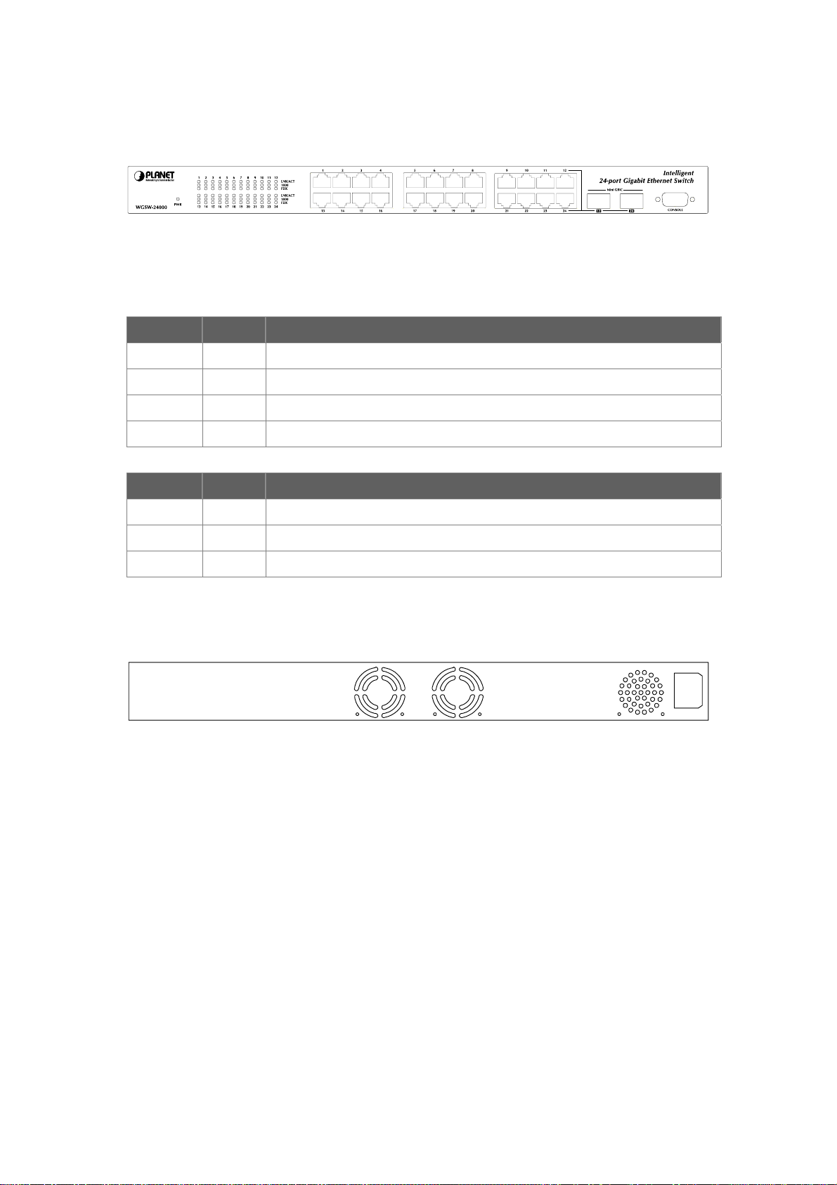
2.1.2 Switch Front Panel
Figure 2-1 shows the front panel of the switch.
Figure 2-1 WGSW-24000 front panel.
2.1.3 LED Indications
Network:
LED Color Function
PWR Green Lights to indicate that the Switch is powered on.
LNK/ACT Green Lights to indicate the link through that port is successfully established.
100 Green Lights to indicate the port is running in 100Mbps speed.
FDX/COL Green Blink to indicate the switch is actively sending or receiving data over that port.
Gigabit:
LED Color Function
LNK/ACT Green Lights to indicate the link through that port is successfully established.
1000 Green Lights to indicate the port is running in 100Mbps speed.
FDX/COL Green Blink to indicate the switch is actively sending or receiving data over that port.
2.1.4 Switch Rear Panel
Figure 2-2 shows the rear panel of the switch
100 ~ 240V AC
50 / 60 Hz
Figure 2-2 WGSW-24000 rear panel.
Power Notice:
1. The device is a power-required device, it means, it will not work till it is powered. If your networks
should active all the time, please consider using UPS (Uninterrupted Power Supply) for your device.
It will prevent you from network data loss or network downtime.
2. In some area, installing a surge suppression device may also help to protect your switch from being
damaged by unregulated surge or current to the Switch or the power adapter.
Page 18

2.2 Install the Switch
This section describes how to install the Ethernet Switch and make connections to it. Please read the
following topics and perform the procedures in the order being presented.
2.2.1 Desktop Installation
To install the Switch on desktop or shelf, please follows these steps:
Step1: Attach the rubber feet to the recessed areas on the bottom of the switch.
Step2: Place the switch on the desktop or the shelf near an AC power source.
Step3: Keep enough ventilation space between the switch and the surrounding objects.
"Note: When choosing a location, please keep in mind the environmental restrictions discussed in
Chapter 1, Section 4, in Specification.
Step4: Connect the Switch to network devices.
A. Connect one end of a standard network cable to the 10/100/1000 RJ-45 ports on the front of the
Switch
B. Connect the other end of the cable to the network devices such as printer servers, workstations
or routers…etc.
"Note: Connection to the Switch requires UTP Category 5 network cabling with RJ-45 tips. For more
information, please see the Cabling Specification in Appendix A.
Step5: Supply power to the switch.
A. Connect one end of the power cable to the switch.
B. Connect the power plug of the power cable to a standard wall outlet.
When the switch receives power, the Power LED should remain solid Green.
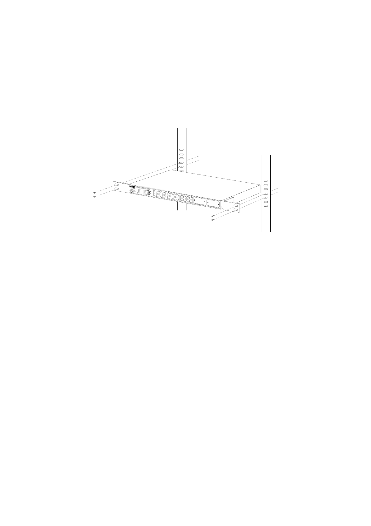
2.2.2 Rack Mounting
To install the switch in a 19-inch standard rack, please follows the instructions described below.
Step1: Place the switch on a hard flat surface, with the front panel positioned towards the front side.
Step2: Attach the rack-mount bracket to each side of the switch with supplied screws attached to the
package.
Figure 2-5 shows how to attach brackets to one side of the switch.
Figure 2-5 Attach brackets to the switch.
Page 19
Caution:
You must use the screws supplied with the mounting brackets. Damage caused to the parts by using
incorrect screws would invalidate the warranty.
Step3: Secure the brackets tightly.
Step4: Follow the same steps to attach the second bracket to the opposite side.
Step5: After the brackets are attached to the Switch, use suitable screws to securely attach the brackets
to the rack, as shown in Figure 2-6
Figure 2-6 Mounting the Switch in a Rack
Step6: Proceeds with the steps 4 and steps 5 of session 2.2.1 Desktop Installation to connect the
network cabling and supply power to the switch.
Page 20

3. CONFIGURATION
This chapter explains the methods that you can use to configure management access to the switch. It
describes the types of management applications and the communication and management protocols that
deliver data between your management device (work-station or personal computer) and the system. It
also contains information about port connection options.
This chapter covers the following topics:
▫ Management Access Overview
▫ Key Concepts
▫ Key Guidelines for Implementation
▫ Administration Console Access
▫ Web Management Access
▫ SNMP Access
▫ Standards, Protocols, and Related Reading
3.1 Management Access Overview
The switch gives you the flexibility to access and manage the switch using any or all of the following
methods:
▫ An administration console
▫ Web browser interface
▫ An external SNMP-based network management application
The administration console and Web browser interface support are embedded in the switch software and
are available for immediate use. Each of these management methods has their own advantages. Table
3-1 compares the three management methods.
Page 21

Method Advantages Disadvantages
Console
Web Browser
SNMP Agent
‧No IP address or subnet needed
‧Text-based
‧Telnet functionality and HyperTerminal
built into Windows 95/98/NT/2000/ME/XP
operating systems
‧Secure
‧Ideal for configuring the switch remotely
‧Compatible with all popular browsers
‧Can be accessed from any location
‧Most visually appealing
‧Communicates with switch functions at
the MIB level
‧Based on open standards
‧Must be near switch or use dial-up
connection
‧Not convenient for remote users
‧Modem connection may prove to be
unreliable or slow
‧Security can be compromised
(hackers need only know the IP address
and subnet mask)
‧May encounter lag times on poor
connections
‧Requires SNMP manager software
‧Least visually appealing of all three
methods
‧Some settings require calculations
‧Security can be compromised
(hackers need only know the
community name)
Table 3-1 Management Methods Comparison
3.1.1 Administration Console
The administration console is an internal, character-oriented, and command line user interface for
performing system administration such as displaying statistics or changing option settings. Using this
method, you can view the administration console from a terminal, personal computer, Apple Macintosh,
or workstation connected to the switch's console (serial) port.
There are two ways to use this management method: via direct access or modem port access. The
following sections describe these methods. For more information about using the console, refer to
Chapter 4 Command Line Interface Console Management.
Page 22

3.1.2 Direct Access
Direct access to the administration console is achieved by directly connecting a terminal or a PC
equipped with a terminal-emulation program (such as HyperTerminal) to the switch console (serial) port.
When using this management method, a null-modem cable is required to connect the switch to the PC.
After making this connection, configure the terminal-emulation program to use the following parameters:
The default parameters are:
▫ 115,200 bps
▫ 8 data bits
▫ No parity
▫ 1 stop bit
You can change these settings, if desired, after you log on. This management method is often preferred
because you can remain connected and monitor the system during system reboots. Also, certain error
messages are sent to the serial port, regardless of the interface through which the associated action was
initiated. A Macintosh or PC attachment can use any terminal-emulation program for connecting to the
terminal serial port. A workstation attachment under UNIX can use an emulator such as TIP.
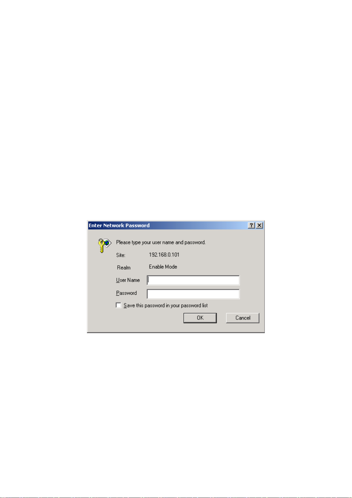
3.2 Web Management
The switch provides a browser interface that lets you configure and manage the switch remotely. After
you set up your IP address for the switch, you can access the switch's Web interface applications directly
in your Web browser by entering the IP address of the switch. You can then use your Web browser to list
and manage switch configuration parameters from one central location, just as if you were directly
connected to the switch's console port.
Web Management requires either Microsoft Internet Explorer 4.01 or later or Netscape Navigator 4.03 or
later.
3.3 SNMP-Based Network Management
You can use an external SNMP-based application to configure and manage the switch. This
management method requires the SNMP agent on the switch and the SNMP Network Management
Station to use the same community string. This management method, in fact, uses two community strings:
the get community string and the set community string. If the SNMP Net-work management Station only
knows the set community string, it can read and write to the MIBs. However, if it only knows the get
community string, it can only read MIBs. The default gets and sets community strings for the switch are
public.
Page 23

3.4 Protocols
The switch supports the following protocols:
▫ Virtual terminal protocols, such as Telnet
▫ Simple Network Management Protocol (SNMP)
3.4.1 Virtual Terminal Protocols
A virtual terminal protocol is a software program, such as Telnet, that allows you to establish a
management session from a Macintosh, a PC, or a UNIX workstation. Because Telnet runs over TCP/IP,
you must have at least one IP address configured on the switch before you can establish access to it with
a virtual terminal protocol.
"Note: Terminal emulation differs from a virtual terminal protocol in that you must connect a terminal
directly to the console (serial) port.
3.4.2 SNMP Protocol
Simple Network Management Protocol (SNMP) is the standard management protocol for multi-vendor IP
networks. SNMP supports transaction-based queries that allow the protocol to format messages and to
transmit information between reporting devices and data-collection programs. SNMP runs on top of the
User Datagram Protocol (UDP), offering a connectionless-mode service.
3.4.3 Management Architecture
All of the management application modules use the same Messaging Application Programming Interface
(MAPI). By unifying management methods with a single MAPI, configuration parameters set using one
method (console port, for example) are immediately displayable by the other management methods (for
example, SNMP agent of Web browser).
The management architecture of the switch adheres to the IEEE open standard. This compliance
assures customers that the switch is compatible with, and will interoperate with other solutions that
adhere to the same open standard.
Page 24
4. Web Configuration
The WGSW-24000 can be configured through an Ethernet connection, make sure the manager PC must
be set on same the IP subnet address with the switch. For example, if you have changed the default IP
address of the Switch to 192.168.16.234 with subnet mask 255.255.255.0 via console, then the manager
PC should be set at 192.168.16.x (where x is a number between 2 and 254) with subnet mask
255.255.255.0. Or you can use the factory default IP address 192.168.0.100 to do the relative
configuration on manager PC.
Use Internet Explorer 5.0 or above Web browser. Enter IP address http://192.168.0.100 (the
factory-default IP address or that you have changed via console) to access the Web interface.
When the following login screen appears, please enter the default username "admin" and no password
(or the username/password you have changed via console) to login the main screen of Switch. The login
screen in Figure 4-1 appears.
Figure 4-1 Login screen
4.1 Main Menu
After a successful login, the main screen appears, the main screen displays the port status and a list of
System section and the topics it provide. As showed in Figure 4-2.
。 System Name - Enter the name you want to use to identify this switch. You may use up to
31 alpha-numeric characters. The factory default is blank.
。 System Location - Enter the location of this switch. You may use up to 31 alpha-numeric
characters. The factory default is blank.
。 System Contact - Enter the contact person for this switch. You may use up to 31
alpha-numeric characters. The factory default is blank.
Page 25
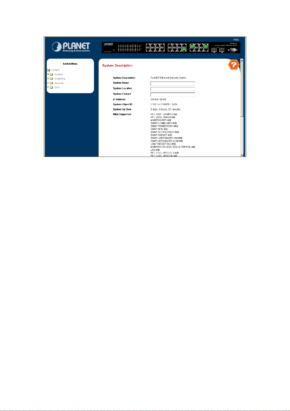
Figure 4-2 main menu screen
4.2 Configure System
The System section provides information for configuring system parameters. Under system the following
topics are provided to configure and view the system information:
。 ARP Cache
。 Inventory Information
。 System Loading
。 Configuration
。 Forward Database
。 Logs
。 Port
。 SNMP
。 Statistics
。 System Utilities
。 Trap Manager
4.2.1 ARP Cache
The Address Resolution Protocol (ARP) dynamically maps physical (MAC) addresses to Internet (IP)
addresses. This panel displays the current contents of the ARP cache.
For each connection, the following information is displayed:
。 The physical (MAC) Address
。 The associated IP address
。 The identification of the port being used for the connection
Page 26
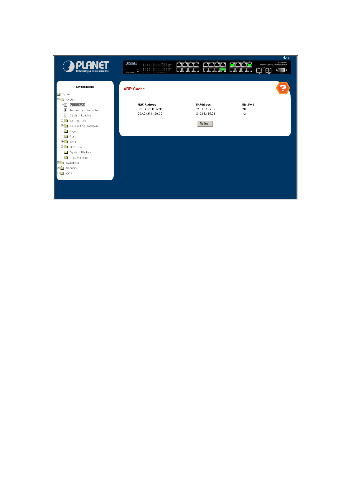
As shows in figure 4-3:
Figure 4-3 ARP Cache
4.2.2 Inventory Information
Use this panel to display the switch's Vital Product Data, stored in non-volatile memory at the factory. The
page includes the following fields:
。 System Description - The product name of this switch.
。 Machine Type - The machine type of this switch.
。 Machine Model - The model within the machine type.
。 Serial Number - The unique box serial number for this switch.
。 FRU Number - The field replaceable unit number.
。 Part Number - The manufacturing part number.
。 Maintenance Level - The identification of the hardware change level.
。 Manufacturer - The two-octet code that identifies the manufacturer.
。 Base MAC Address - The burned-in universally administered MAC address of this switch.
。 Software Version - The release version maintenance number of the code currently running
on the switch. For example, if the release was 1, the version was 2 and the maintenance
number was 4, the format would be '1.2.4'.
。 Operating System - The operating system currently running on the switch.
。 Network Processing Device - Identifies the network processor hardware.
。 Additional Packages - A list of the optional software packages installed on the switch, if
any. For example, FASTPATH BGP-4, or FASTPATH Multicast.
Page 27
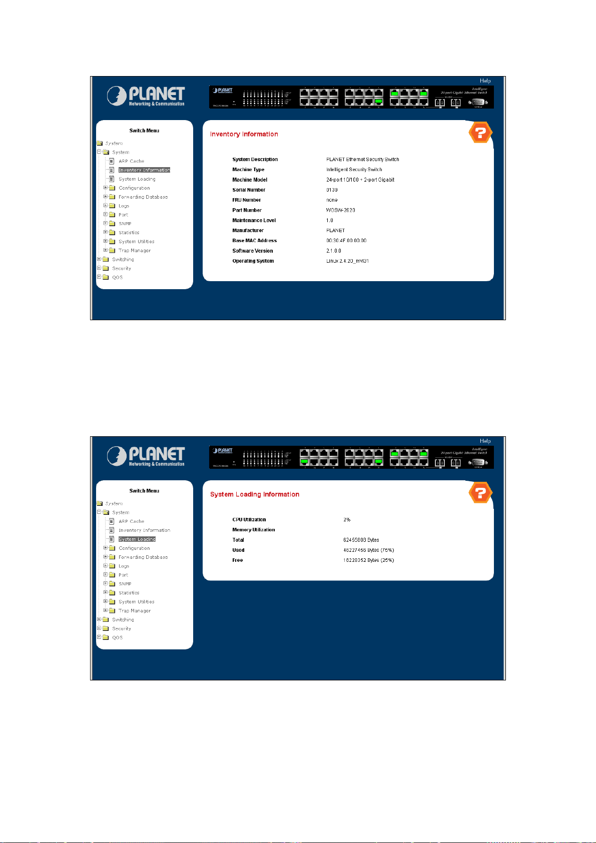
Figure 4-4 Inventory Information
4.2.3 System Loading
This page shows the system loading information, including the following fields:
。 CPU Utilization – The CPU usage percentage
。 Memory Utilization – The total Memory size and the usage information
Figure 4-5 System Loading
Page 28

4.2.4 Configuration
Use this page to configure the parameters for system management, including the following fields:
。 System Description
。 Switch
。 Network Connectivity
。 Remote Session
。 Serial Port
。 User Account
。 Authentication List Configuration
。 Login Session
。 Authentication List Summary
。 User Login
。 Single IP Management
。 Single IP Mgmt Swap Control
4.2.4.1 System Description
This page shows the basic system information and is available to define the system name, location and
contact person. Includes the following fields:
。 System Name - Enter the name you want to use to identify this switch. You may use up to
31 alpha-numeric characters. The factory default is blank.
。 System Location - Enter the location of this switch. You may use up to 31 alpha-numeric
characters. The factory default is blank.
。 System Contact - Enter the contact person for this switch. You may use up to 31
alpha-numeric characters. The factory default is blank.
。 System Description - The product name of this switch.
。 System Object ID - The base object ID for the switch's enterprise MIB.
。 System IP Address - The IP Address assigned to the network interface.
。 System Up time - The time in days, hours and minutes since the last switch reboot.
。 MIBs Supported - The list of MIBs supported by the management agent running on this
switch.
Page 29
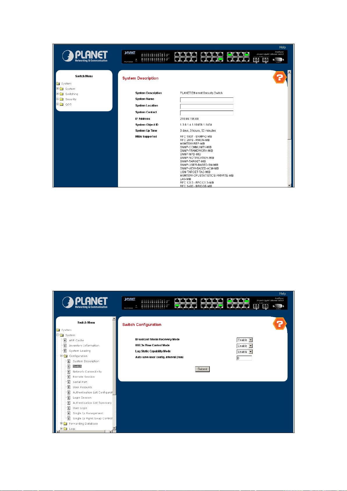
Figure 4-6 System Description
4.2.4.2 Switch Configuration
This page includes the following fields:
。 Broadcast Storm Recovery Mode - Enable or disable this option by selecting the
corresponding line on the pull-down entry field. The factory default is disabled.
。 IEEE 802.3x Flow Control Mode - Enable or disable this option by selecting the
corresponding line on the pull-down entry field. The factory default is disabled.
。 Lag Static Capability Mode - May be enabled or disabled by selecting the corresponding
line on the pull-down entry field. The factory default is disabled.
Figure 4-7 Switch Configuration
Page 30

4.2.4.3 Network Connectivity
The network interface is the logical interface used for in-band connectivity with the switch via any of the
switch's front panel ports. The configuration parameters associated with the switch's network interface do
not affect the configuration of the front panel ports through which traffic is switched or routed.
To access the switch over a network you must first configure it with IP information (IP address, subnet
mask, and default gateway). You can configure the IP information using any of the following:
。 BOOTP
。 DHCP
。 Terminal interface via the EIA-232 port
Once you have established in-band connectivity, you can change the IP information using any of the
following:
。 Terminal interface via the EIA-232 port
。 Terminal interface via telnet
。 SNMP-based management
。 Web-based management
The page includes the following configurable data:
。 IP Address - The IP address of the interface. The factory default value is 0.0.0.0
。 Subnet Mask - The IP subnet mask for the interface. The factory default value is 0.0.0.0
。 Default Gateway - The default gateway for the IP interface. The factory default value is
0.0.0.0
。 Locally Administered MAC Address - You may configure a locally administered MAC
address for in-band connectivity instead of using the burned-in universally administered
MAC address. In addition to entering an address in this field, you must also set the MAC
address type to locally administered. Enter the address as twelve hexadecimal digits (6
bytes) with a colon between each byte. Bit 1 of byte 0 must be set to a 1 and bit 0 to a 0, i.e.
byte 0 must have a value between x'40' and x'7F'.
。 MAC Address type - Specify whether the burned-in or the locally administered MAC
address should be used for in-band connectivity. The factory default is to use the burned-in
MAC address
。 Network Configuration Protocol Current - Choose what the switch should do following
power-up: transmit a Bootp request, transmit a DHCP request, or do nothing (none). The
factory default is DHCP.
。 Management VLAN ID - Specifies the management VLAN ID of the switch. It may be
configured to any value in the range of 1 - 4093. The management VLAN is used for
management of the switch. This field is configurable for administrative users and read-only
for other users.
。 Web Mode - Specify whether the switch may be accessed from a web browser. If you
choose to enable web mode you will be able to manage the switch from a web browser. The
Page 31

factory default is enabled.
。 Java Mode - Enable or disable the java applet that displays a picture of the switch at the top
right of the screen. If you run the applet you will be able to click on the picture of the switch
to select configuration screens instead of using the navigation tree at the left side of the
screen. The factory default is disabled.
The following data are non-configurable:
。 Burned-in MAC Address - The burned-in MAC address used for in-band connectivity if you
choose not to configure a locally administered address.
。 Network Configuration Protocol Current - Indicates what network protocol was used on
the last, or current power-up cycle, if any.
Figure 4-8 Network Connectivity Configuration
4.2.4.4 Remote Session
This page includes the following fields:
。 Remote Login Timeout (minutes) - Specify how many minutes of inactivity should occur
on a telnet or SSH session before the switch logs off. A zero means there will be no timeout.
You may enter any number from 0 to 160. The factory default is 5.
。 Maximum Number of Remote Sessions - Use the pull-down menu to select how many
simultaneous telnet or SSH sessions will be allowed. The maximum is 5, which is also the
factory default.
。 Allow New Remote Sessions - If you set this to no, new telnet sessions will not be allowed.
The factory default is yes.
Page 32

Figure 4-9 Remote Session
4.2.4.5 Serial Port
Use this page to define the parameters of console connectivity. The configurable data are:
。 Serial Port Login Timeout (minutes) - Specify how many minutes of inactivity should
occur on a serial port connection before the switch closes the connection. Enter a number
between 0 and 160: the factory default is 5. Entering 0 disables the timeout.
。 Baud Rate (bps) - Select the default baud rate for the serial port connection from the
pull-down menu. You may choose from 1200, 2400, 4800, 9600, 19200, 38400, 57600, and
115200 baud. The factory default is 115200 baud.
And the non-configurable data:
。 Character Size (bits) - The number of bits in a character. This is always 8.
。 Flow Control - Whether hardware flow control is enabled or disabled. It is always disabled.
。 Parity - The parity method used on the serial port. It is always None.
。 Stop Bits - The number of stop bits per character. The value is always 1.
Page 33

Figure 4-10 Serial Port Configuration
4.2.4.6 User Accounts
By default, two user accounts exist:
。 admin, with 'Read/Write' privileges
。 guest, with 'Read Only' privileges
By default, both of these accounts have blank passwords. The names are not case sensitive.
If you logon with a user account with 'Read/Write' privileges (i.e. as admin) you can use the User
Accounts screen to assign passwords and set security parameters for the default accounts, and to add
and delete accounts (other than admin) up to the maximum of six. Only a user with 'Read/Write'
privileges may alter data on this screen, and only one account may be created with 'Read/Write'
privileges.
Selection Criteria
。 User Name Selector - You can use this screen to reconfigure an existing account, or to
create a new one. Use this pull-down menu to select one of the existing accounts, or select
'Create' to add a new one, provided the maximum of five 'Read Only' accounts has not been
reached.
Configurable Data
。 User Name - Enter the name you want to give to the new account. (You can only enter data
in this field when you are creating a new account.) User names are up to eight characters in
length and are not case sensitive. Valid characters include all the alphanumeric characters
as well as the dash ('-') and underscore ('_') characters.
。 Password - Enter the optional new or changed password for the account. It will not display
as it is typed, only asterisks(*) will show. Passwords are up to eight alpha numeric
characters in length, and are case sensitive.
Page 34

。 Confirm Password - Enter the password again, to confirm that you entered it correctly. This
field will not display, but will show asterisks (*)
。 Authentication Protocol - Specify the SNMPv3 Authentication Protocol setting for the
selected user account. The valid Authentication Protocols are None, MD5 or SHA. If you
select None, the user will be unable to access the SNMP data from an SNMP browser. If
you select MD5 or SHA, the user login password will be used as the SNMPv3 authentication
password, and you must therefore specify a password, and it must be eight characters long.
。 Encryption Protocol - Specify the SNMPv3 Encryption Protocol setting for the selected
user account. The valid Encryption Protocols are None or DES. If you select the DES
Protocol you must enter a key in the Encryption Key field. If None is specified for the
Protocol, the Encryption Key is ignored.
。 Encrypt ion Key - If you selected DES in the Encryption Protocol field enter the SNMPv3
Encryption Key here. Otherwise this field is ignored. Valid keys are 0 to 15 characters long.
The Apply checkbox must be checked in order to change the Encryption Protocol and
Encryption Key.
Non-Configurable Data
。 Access Mode - Indicates the user's access mode. The admin account always has
'Read/Write' access, and all other accounts have 'Read Only' access.
。 SNMP v3 Access Mode - Indicates the SNMPv3 access privileges for the user account.
The admin account always has 'Read/Write' access, and all other accounts have 'Read
Only' access.
Figure 4-11 User Accounts
Page 35

4.2.4.7 Authentication List Configuration
Use this screen to configure login lists. A login list specifies the authentication method(s) you want used
to validate switch or port access for the users associated with the list. The pre-configured users, admin
and guest, are assigned to a pre-configured list named defaultList, which you may not delete. All newly
created users are also assigned to the defaultList until you specifically assign them to a different list
Selection Criteria
。 Authentication List - Select the authentication login list you want to configure. Select
'create' to define a new login list. When you create a new login list, 'local' is set as the initial
authentication method.
Configurable Data
。 Authentication List Name - If you are creating a new login list, enter the name you want to
assign. It can be up to 15 alphanumeric characters long and is not case sensitive.
。 Method 1 - Use the dropdown menu to select the method that should appear first in the
selected authentication login list. If you select a method that does not time out as the first
method, such as 'local' no other method will be tried, even if you have specified more than
one method. Note that this parameter will not appear when you first create a new login list.
The options are:
¾ Local- the user's locally stored ID and password will be used for authentication
¾ Radius- the user's ID and password will be authenticated using the RADIUS server
instead of locally
¾ Reject- the user is never authenticated
¾ Undefined- the authentication method is unspecified (this may not be assigned as
the first method)
。 Method 2 - Use the dropdown menu to select the method, if any, that should appear second
in the selected authentication login list. This is the method that will be used if the first
method times out. If you select a method that does not time out as the second method, the
third method will not be tried. Note that this parameter will not appear when you first create
a new login list.
。 Method 3 - Use the dropdown menu to select the method, if any, that should appear third in
the selected authentication login list. Note that this parameter will not appear when you first
create a new login list.
Page 36

Figure 4-12 Authentication List Configuration – Create User
Figure 4-13 Authentication List Configuration – DefaultList
4.2.4.8 Login Session
This page shows the information of login session, including:
。 ID - Identifies the ID of this row.
。 User Name - Shows the user name of user made the session.
。 Connection From - Shows the user is connected from which machine.
。 Idle Time - Shows the idle session time.
。 Session Time - Shows the total session time.
Page 37

Figure 4-14 Login Sessions
4.2.4.9 Authentication List Summary
This page lists the authenticate user, the information fields include:
。 Authentication List - Identifies the authentication login list summarized in this row.
。 Method List - The ordered list of methods configured for this login list.
。 Login Users - The users you assigned to this login list on the User Login Configuration
screen. This list is used to authenticate the users for system login access.
。 802.1x Port Security Users - The users you assigned to this login list on the Port Access
Control User Login Configuration screen - This list is used to authenticate the users for port
access, using the IEEE 802.1x protocol.
Page 38

Figure 4-15 Authentication List Summary
4.2.4.10 User Login
Each configured user is assigned to a login list that specifies how the user should be authenticated when
attempting to access the switch or a port on the switch. After creating a new user account on the User
Account screen, you should assign that user to a login list for the switch using this screen and, if
necessary, to a login list for the ports using the Port Access Control User Login Configuration screen. If
you need to create a new login list for the user, you would do so on the Login Configuration screen.
The pre-configured users, admin and guest, are assigned to a pre-configured list named defaultList,
which you may not delete. All newly created users are also assigned to the defaultList until you
specifically assign them to a different list.
A user that does not have an account configured on the switch is termed the 'default' or
'non-configured' user. If you assign the 'non-configured user' to a login list that specifies authentication
via the RADIUS server, you will not need to create an account for all users on each switch. However, by
default the 'non-configured user' is assigned to 'defaultList', which by default uses local
authentication.
Selection Criteria
。 User - Select the user you want to assign to a login list. Note that you must always
associate the admin user with the default list. This forces the admin user to always be
authenticated locally to prevent full lockout from switch configuration. If you assign a user to
a login list that requires remote authentication, the user's access to the switch from all CLI,
web, and telnet sessions will be blocked until the authentication is complete. Refer to the
discussion of maximum delay in the RADIUS configuration help.
Configurable Data
。 Authentication List - Select the authentication login list you want to assign to the user for
system login.
Page 39

Figure 4-10 User Login Configuration
4.2.4.11 Simple IP Management
Use this page to configure the stacking WGSW-24000/WGSW-2620 in a single IP Address.
。 Single Ip Management - Enable or disable this option by selecting the corresponding line
on the pull-down entry field. The factory default is disabled.
。 Group ID - Enable or disable this option by selecting the corresponding line on the
pull-down entry field. The factory default is disabled.
。 Switch ID - May be enabled or disabled by selecting the corresponding line on the
pull-down entry field. The factory default is disabled.
。 IP Address - The IP address for the single ip management IP interface. The factory default
value is 0.0.0.0.
。 Subnet Mask - The IP subnet mask for the single ip management IP interface. The factory
default value is 0.0.0.0.
。 Default Gateway - The default gateway for the single ip management IP interface. The
factory default value is 0.0.0.0.
。 Client Switch Id - The id of client switches in the same single ip management group. Only
the master switch can see this information
Page 40

Figure 4-11 Single ip Management
4.2.4.12 Single Ip Mgmt Swap Control
Use this page to swap the Master switch to control to.
。 Swap Master Switch To - The switch Id which you are going to swap to control it.
Figure 4-12 Single Ip Management Swap Control
Page 41

4.2.5 Forwarding Database
4.2.5.1 Configuration
Use this panel to set the Address Ageing Timeout for the forwarding database.
。 Address Ageing Timeout (seconds) - The forwarding database contains static entries,
which are never aged out, and dynamically learned entries, which are removed if they are
not updated within a given time. You specify that time by entering a value for the Address
Ageing Timeout. You may enter any number of seconds between 10 and 1000000. IEEE
802.1D recommends a default of 300 seconds, which is the factory default.
Figure 4-13 Forwarding Database
4.2.5.2 Search
Use this panel to display information about entries in the forwarding database. These entries are used by
the transparent bridging function to determine how to forward a received frame.
Configurable Data
。 Filter - Specify the entries you want displayed.
¾ Learned: If you choose "learned" only MAC addresses that have been learned will be
displayed.
¾ All: If you choose "all" the whole table will be displayed.
。 MAC Address Search - You may also search for an individual MAC address. Enter the two
byte hexadecimal VLAN ID followed by the six byte hexadecimal MAC address in two-digit
groups separated by colons, for example 01:23:45:67:89:AB:CD:EF where 01:23 is the
VLAN ID and 45:67:89:AB:CD:EF is the MAC address. Then click on the search button. If
the address exists, that entry will be displayed as the first entry followed by the remaining
(greater) MAC addresses. An exact match is required.
Page 42

Figure 4-14 Forwarding Database Search
4.2.6 Logs
4.2.6.1 Message Log
Use this panel to display the message log maintained by the switch. The message log contains system
trace information that records non-critical problems. Message log information is not retained across a
switch reset and wraps after 512 entries.
Non-Configurable Data
。 Time - The time the event was logged, calculated from the time the switch was last reset.
。 Filename - The FASTPATH source code filename identifying the code that detected the
event.
。 Line number - The line number within the file of the code that detected the event.
。 Description - An explanation of the problem being reported.
Page 43

Figure 4-15 Message Log
4.2.7 Port
4.2.7.1 Configuration
Use this page to configure the parameters of the distinct port.
Selection Criteria
。 Slot.Port - Selects the interface for which data is to be displayed or configured.
Configurable Data
。 STP Mode - The Select the Spanning Tree Protocol Administrative Mode for the port or LAG.
The possible values are:
¾ Enable - select this to enable the Spanning Tree Protocol for this port.
¾ Disable - select this to disable the Spanning Tree Protocol for this port.
。 Admin Mode - Use the pull-down menu to select the Port control administration state. You
must select enable if you want the port to participate in the network. The factory default is
enabled.
。 LACP Mode - Selects the Link Aggregation Control Protocol administration state. The mode
must be enabled in order for the port to participate in Link Aggregation. May be enabled or
disabled by selecting the corresponding line on the pull-down entry field. The factory default
is enabled.
。 Physical Mode - Use the pull-down menu to select the port's speed and duplex mode. If
you select auto the duplex mode and speed will be set by the auto-negotiation process.
Note that the port's maximum capability (full duplex and 100 Mbps) will be advertised.
Otherwise, your selection will determine the port's duplex mode and transmission rate. The
factory default is auto. The selection when applied against the "All" option in Slot.Port is
Page 44
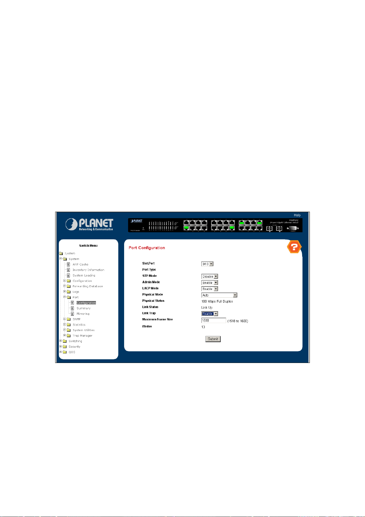
applied to all applicable interfaces only.
。 Link Trap - This object determines whether or not to send a trap when link status changes.
The factory default is enabled.
。 Maximum Frame Size - The maximum Ethernet frame size the interface supports or is
configured, including Ethernet header, CRC, and payload. (1518 to 1600). The default
maximum frame size is 1518.
Non-Configurable Data
。 Port Type - For normal ports this field will be blank. Otherwise the possible values are:
¾ Mon - the port is a monitoring port. Look at the Port Monitoring screens for more
information.
¾ LAG - the port is a member of a Link Aggregation trunk. Look at the LAG screens for
more information.
。 Physical Status - Indicates the port speed and duplex mode.
。 Link Status - Indicates whether the Link is up or down.
。 ifIndex - The ifIndex of the interface table entry associated with this port.
Figure 4-16 Port Configuration
4.2.7.2 Summary
This screen displays the status for all ports in the box.
Selection Criteria
。 MST ID - Select the Multiple Spanning Tree instance ID from the list of all currently
configured MST ID's to determine the values displayed for the Spanning Tree parameters.
Changing the selected MST ID will generate a screen refresh. If Spanning Tree is disabled
this will be a static value, CST, instead of a selector.
Non-Configurable Port Status Data
Page 45

。 Slot.Port - Identifies the port
。 Port Type - For normal ports this field will be blank. Otherwise the possible values are:
¾ Mon - this port is a monitoring port. Look at the Port Monitoring screens for more
information.
¾ LAG - the port is a member of a Link Aggregation trunk. Look at the LAG screens for
more information.
。 STP Mode - The Spanning Tree Protocol Administrative Mode associated with the port or
LAG. The possible values are:
¾ Enable - spanning tree is enabled for this port.
¾ Disable - spanning tree is disabled for this port.
。 Forwarding State - The port's current state Spanning Tree state. This state controls what
action a port takes on receipt of a frame. If the bridge detects a malfunctioning port it will
place that port into the broken state. The other five states are defined in IEEE 802.1D:
¾ Disabled
¾ Blocking
¾ Listening
¾ Learning
¾ Forwarding
¾ Broken
。 Port Role - Each MST Bridge Port that is enabled is assigned a Port Role for each
spanning tree. The port role will be one of the following values: Root Port, Designated Port,
Alternate Port, Backup Port, Master Port or Disabled Port.
。 Admin Mode - The Port control administration state. The port must be enabled in order for
it to be allowed into the network. The factory default is enabled.
。 LACP Mode - Indicates the Link Aggregation Control Protocol administration state. The
mode must be enabled in order for the port to participate in Link Aggregation.
。 Physical Mode - Indicates the port speed and duplex mode. In auto-negotiation mode the
duplex mode and speed are set from the auto-negotiation process.
。 Physical Status - Indicates the port speed and duplex mode.
。 Link Status - Indicates whether the Link is up or down.
。 Link Trap - Indicates whether or not the port will send a trap when link status changes.
。 ifIndex - Indicates the ifIndex of the interface table entry associated with this port.
Page 46

Figure 4-17 Port Summary
4.2.7.3 Port Mirroring
Use this page to configure the port mirror function.
。 Port Mirroring Mode - Selects the Port Mirroring Mode. May be enabled or disabled by
selecting the corresponding line on the pull-down entry field. The factory default is disabled.
。 Probe Port - The interface selected as the Probe. Once configured there shall be no
network connectivity on the probe port. Probe port will not forward any traffic and will not
receive anything. The Probe tool attached to the probe port will not be able to ping the
switch or through the switch, and nobody will be able to ping the probe tool.
。 Port to be Mirrored - The interface selected as the Mirror. Every packet seen at the
mirrored port is copied to the probe port. That includes all packets received and admitted,
received and dropped, and transmitted (not including frames received in error e.g. incorrect
CRC) out of the mirrored port.
Page 47

Figure 4-18 Port Mirroring
4.2.8 SNMP
4.2.8.1 Community Configuration
By default, two SNMP Communities exist:
。 private, with 'Read/Write' privileges and status set to enable
。 public, with 'Read Only' privileges and status set to enable
These are well-known communities; you can use this menu to change the defaults or to add other
communities. Only the communities that you define using this menu will have access to the switch using
the SNMPv1 and SNMPv2c protocols. Only those communities with read-write level access will have
access to this menu via SNMP.
You should use this menu when you are using the SNMPv1 and SNMPv2c protocol: if you want to use
SNMP v3 you should use the User Accounts menu.
Configurable Data
。 SNMP Community Name - You can use this screen to reconfigure an existing community,
or to create a new one. Use this pull-down menu to select one of the existing community
names, or select 'Create' to add a new one. A valid entry is a case-sensitive string of up to
16 characters.
。 Client IP Address - Taken together, the Client IP Address and Client IP Mask denote a
range of IP addresses from which SNMP clients may use that community to access this
device. If either (IP Address or IP Mask) value is 0.0.0.0, access is allowed from any IP
address. Otherwise, every client's IP address is ANDed with the mask, as is the Client IP
Address, and, if the values are equal, access is allowed. For example, if the Client IP
Address and Client IP Mask parameters are 192.168.1.0/255.255.255.0, then any client
Page 48

whose IP address is 192.168.1.0 through 192.168.1.255 (inclusive) will be allowed access.
To allow access from only one station, use a Client IP Mask value of 255.255.255.255, and
use that machine's IP address for Client IP Address.
。 Client IP Mask - Taken together, the Client IP Address and Client IP Mask denote a range
of IP addresses from which SNMP clients may use that community to access this device. If
either (IP Address or IP Mask) value is 0.0.0.0, access is allowed from any IP address.
Otherwise, every client's IP address is ANDed with the mask, as is the Client IP Address,
and, if the values are equal, access is allowed. For example, if the Client IP Address and
Client IP Mask parameters are 192.168.1.0/255.255.255.0, then any client whose IP
address is 192.168.1.0 through 192.168.1.255 (inclusive) will be allowed access. To allow
access from only one station, use a Client IP Mask value of 255.255.255.255, and use that
machine's IP address for Client IP Address.
。 Access Mode - Specify the access level for this community by selecting Read/Write or
Read Only from the pull-down menu.
。 Status - Specify the status of this community by selecting Enable or Disable from the
pull-down menu. If you select enable, the Community Name must be unique among all valid
Community Names or the set request will be rejected. If you select disable, the Community
Name will become invalid.
Figure 4-19 SNMP Community
4.2.8.2 Trap Receiver Configuration
This menu will display an entry for every active Trap Receiver.
。 SNMP Community Name - Enter the community string for the SNMP trap packet to be sent
to the trap manager. This may be up to 16 characters and is case sensitive.
。 IP Address - Enter the IP address to receive SNMP traps from this device. Enter 4 numbers
Page 49

between 0 and 255 separated by periods.
。 Status - Select the receiver's status from the pulldown menu:
。 Enable - send traps to the receiver
。 Disable - do not send traps to the receiver.
Figure 4-20 SNMP Trap Receiver
4.2.8.3 Supported MIBS
This is a list of all the MIBs supported by the switch.
。 Name - The RFC number if applicable and the name of the MIB.
。 Description - The RFC title or MIB description.
。 Refresh - Update the data.
Page 50

Figure 4-21 SNMP Supported MIBs
4.2.9 Statistics
4.2.9.1 Switch Detail
This page shows the detail information of the switch, including the following data:
。 ifIndex - This object indicates the ifIndex of the interface table entry associated with the
Processor of this switch.
。 Octets Received - The total number of octets of data received by the processor (excluding
framing bits but including FCS octets).
。 Unicast Packets Received - The number of subnetwork-unicast packets delivered to a
higher-layer protocol.
。 Multicast Packets Received - The total number of packets received that were directed to a
multicast address. Note that this number does not include packets directed to the broadcast
address.
。 Broadcast Packets Received - The total number of packets received that were directed to
the broadcast address. Note that this does not include multicast packets.
。 Receive Packets Discarded - The number of inbound packets which were chosen to be
discarded even though no errors had been detected to prevent their being deliverable to a
higher-layer protocol. A possible reason for discarding a packet could be to free up buffer
space.
。 Octets Transmitted - The total number of octets transmitted out of the interface, including
framing characters.
。 Packets Transmitted Without Errors - The total number of packets transmitted out of the
interface.
。 Unicast Packets Transmitted - The total number of packets that higher-level protocols
requested be transmitted to a subnetwork-unicast address, including those that were
discarded or not sent.
。 Multicast Packets Transmitted - The total number of packets that higher-level protocols
requested be transmitted to a Multicast address, including those that were discarded or not
sent.
。 Broadcast Packets Transmitted - The total number of packets that higher-level protocols
requested be transmitted to the Broadcast address, including those that were discarded or
not sent.
。 Transmit Packets Discarded - The number of outbound packets which were chosen to be
discarded even though no errors had been detected to prevent their being deliverable to a
higher-layer protocol. A possible reason for discarding a packet could be to free up buffer
space.
。 Most Address Entries Ever Used - The highest number of Forwarding Database Address
Page 51

Table entries that have been learned by this switch since the most recent reboot.
。 Address Entries in Use - The number of Learned and static entries in the Forwarding
Database Address Table for this switch.
。 Maximum VLAN Entries - The maximum number of Virtual LANs (VLANs) allowed on this
switch.
。 Most VLAN Entries Ever Used - The largest number of VLANs that have been active on
this switch since the last reboot.
。 Static VLAN Entries - The number of presently active VLAN entries on this switch that
have been created statically.
。 Dynamic VLAN Entries - The number of presently active VLAN entries on this switch that
have been created by GVRP registration.
。 VLAN Deletes - The number of VLANs on this switch that have been created and then
deleted since the last reboot.
。 Time Since Counters Last Cleared - The elapsed time, in days, hours, minutes, and
seconds, since the statistics for this switch were last cleared.
Figure 4-22 Switch Detailed Statistics
4.2.9.2 Switch Summary
。 ifIndex - This object indicates the ifIndex of the interface table entry associated with the
Processor of this switch.
。 Broadcast Packets Received - The total number of packets received that were directed to
the broadcast address. Note that this does not include multicast packets.
。 Packets Received With Error - The number of inbound packets that contained errors
preventing them from being deliverable to a higher-layer protocol.
。 Packets Transmitted Without Errors - The total number of packets transmitted out of the
Page 52

interface.
。 Broadcast Packets Transmitted - The total number of packets that higher-level protocols
requested to be transmitted to the Broadcast address, including those that were discarded
or not sent.
。 Transmit Packet Errors - The number of outbound packets that could not be transmitted
because of errors.
。 Address Entries Currently in Use - The total number of Forwarding Database Address
Table entries now active on the switch, including learned and static entries.
。 VLAN Entries Currently in Use - The number of VLAN entries presently occupying the
VLAN table.
。 Time Since Counters Last Cleared - The elapsed time, in days, hours, minutes, and
seconds since the statistics for this switch were last cleared.
Figure 4-23 Switch Summary Statistics
4.2.9.3 Port Detailed
Selection Criteria
。 Slot.Port - Selects the interface for which data is to be displayed or configured.
Non-Configurable Data
。 ifIndex - This object indicates the ifIndex of the interface table entry associated with this
port on an adapter.
。 Packets RX and TX 64 Octets - The total number of packets (including bad packets)
received or transmitted that were 64 octets in length (excluding framing bits but including
FCS octets).
。 Packets RX and TX 65-127 Octets - The total number of packets (including bad packets)
received or transmitted that were between 65 and 127 octets in length inclusive (excluding
Page 53

framing bits but including FCS octets).
。 Packets RX and TX 128-255 Octets - The total number of packets (including bad packets)
received or transmitted that were between 128 and 255 octets in length inclusive (excluding
framing bits but including FCS octets).
。 Packets RX and TX 256-511 Octets - The total number of packets (including bad packets)
received or transmitted that were between 256 and 511 octets in length inclusive (excluding
framing bits but including FCS octets).
。 Packets RX and TX 512-1023 Octets - The total number of packets (including bad packets)
received or transmitted that were between 512 and 1023 octets in length inclusive
(excluding framing bits but including FCS octets).
。 Packets RX and TX 1024-1518 Octets - The total number of packets (including bad
packets) received or transmitted that were between 1024 and 1518 octets in length
inclusive (excluding framing bits but including FCS octets).
。 Packets RX and TX 1519-1522 Octets - The total number of packets (including bad
packets) received or transmitted that were between 1519 and 1522 octets in length
inclusive (excluding framing bits but including FCS octets).
。 Packets RX and TX 1523-2047 Octets - The total number of packets (including bad
packets) received or transmitted that were between 1523 and 2047 octets in length
inclusive (excluding framing bits but including FCS octets).
。 Packets RX and TX 2048-4095 Octets - The total number of packets (including bad
packets) received or transmitted that were between 2048 and 4095 octets in length
inclusive (excluding framing bits but including FCS octets).
。 Packets RX and TX 4096-9216 Octets - The total number of packets (including bad
packets) received or transmitted that were between 4096 and 9216 octets in length
inclusive (excluding framing bits but including FCS octets).
。 Octets Received - The total number of octets of data (including those in bad packets)
received on the network (excluding framing bits but including FCS octets). This object can
be used as a reasonable estimate of Ethernet utilization. If greater precision is desired, the
etherStatsPkts and etherStatsOctets objects should be sampled before and after a common
interval.
。 Packets Received > 1522 Octets - The total number of packets received that were longer
than 1522 octets (excluding framing bits, but including FCS octets) and were otherwise well
formed.
。 Total Packets Received Without Errors - The total number of packets received that were
without errors.
。 Unicast Packets Received - The number of subnetwork-unicast packets delivered to a
higher-layer protocol.
。 Multicast Packets Received - The total number of good packets received that were
Page 54

directed to a multicast address. Note that this number does not include packets directed to
the broadcast address.
。 Broadcast Packets Received - The total number of good packets received that were
directed to the broadcast address. Note that this does not include multicast packets.
。 Total Packets Received with MAC Errors - The total number of inbound packets that
contained errors preventing them from being deliverable to a higher-layer protocol.
。 Jabbers Received - The total number of packets received that were longer than 1518
octets (excluding framing bits, but including FCS octets), and had either a bad Frame Check
Sequence (FCS) with an integral number of octets (FCS Error) or a bad FCS with a
non-integral number of octets (Alignment Error). Note that this definition of jabber is different
than the definition in IEEE-802.3 section 8.2.1.5 (10BASE5) and section 10.3.1.4
(10BASE2). These documents define jabber as the condition where any packet exceeds 20
ms. The allowed range to detect jabber is between 20 ms and 150 ms.
。 Fragments/Undersize Received - The total number of packets received that were less
than 64 octets in length (excluding framing bits but including FCS octets).
。 Alignment Errors - The total number of packets received that had a length (excluding
framing bits, but including FCS octets) of between 64 and 1518 octets, inclusive, but had a
bad Frame Check Sequence (FCS) with a non-integral number of octets.
。 Rx FCS Errors - The total number of packets received that had a length (excluding framing
bits, but including FCS octets) of between 64 and 1518 octets, inclusive, but had a bad
Frame Check Sequence (FCS) with an integral number of octets
。 Overruns - The total number of frames discarded as this port was overloaded with
incoming packets, and could not keep up with the inflow.
。 Total Received Packets Not Forwarded - A count of valid frames received which were
discarded (i.e. filtered) by the forwarding process.
。 Local Traffic Frames - The total number of frames dropped in the forwarding process
because the destination address was located off of this port.
。 802.3x Pause Frames Received - A count of MAC Control frames received on this
interface with an opcode indicating the PAUSE operation. This counter does not increment
when the interface is operating in half-duplex mode.
。 Unacceptable Frame Type - The number of frames discarded from this port due to being
an unacceptable frame type.
。 Multicast Tree Viable Discards - The number of frames discarded when a lookup in the
multicast tree for a VLAN occurs while that tree is being modified.
。 Reserved Address Discards - The number of frames discarded that are destined to an
IEEE 802.1 reserved address and are not supported by the system.
。 Broadcast Storm Recovery - The number of frames discarded that are destined for
FF:FF:FF:FF:FF:FF when Broadcast Storm Recovery is enabled.
Page 55

。 CFI Discards - The number of frames discarded that have CFI bit set and the addresses in
RIF are in non-canonical format.
。 Upstream Threshold - The number of frames discarded due to lack of cell descriptors
available for that packet's priority level.
。 Total Packets Transmitted (Octets) - The total number of octets of data (including those in
bad packets) transmitted on the network (excluding framing bits but including FCS octets).
This object can be used as a reasonable estimate of Ethernet utilization. If greater precision
is desired, the etherStatsPkts and etherStatsOctets objects should be sampled before and
after a common interval.
。 Packets Transmitted 1523-2047 Octets - The total number of packets (including bad
packets) received that were between 1523 and 2047 octets in length inclusive (excluding
framing bits but including FCS octets).
。 Packets Transmitted 2048-4095 Octets - The total number of packets (including bad
packets) received that were between 2048 and 4095 octets in length inclusive (excluding
framing bits but including FCS octets).
。 Packets Transmitted 4096-9216 Octets - The total number of packets (including bad
packets) received that were between 4096 and 9216 octets in length inclusive (excluding
framing bits but including FCS octets).
。 Maximum Frame Size - The maximum Ethernet frame size the interface supports or is
configured, including Ethernet header, CRC, and payload. (1518 to 1600). The default
maximum frame size is 1518.
。 Total Packets Transmitted Successfully - The number of frames that have been
transmitted by this port to its segment.
。 Unicast Packets Transmitted - The total number of packets that higher-level protocols
requested be transmitted to a subnetwork-unicast address, including those that were
discarded or not sent.
。 Multicast Packets Transmitted - The total number of packets that higher-level protocols
requested be transmitted to a Multicast address, including those that were discarded or not
sent.
。 Broadcast Packets Transmitted - The total number of packets that higher-level protocols
requested be transmitted to the Broadcast address, including those that were discarded or
not sent.
。 Total Transmit Errors - The sum of Single, Multiple, and Excessive Collisions.
。 Tx FCS Errors - The total number of packets transmitted that had a length (excluding
framing bits, but including FCS octets) of between 64 and 1518 octets, inclusive, but had a
bad Frame Check Sequence (FCS) with an integral number of octets
。 Tx Oversized - The total number of frames that exceeded the max permitted frame size.
This counter has a max increment rate of 815 counts per sec at 10 Mb/s.
Page 56

。 Underrun Errors - The total number of frames discarded because the transmit FIFO buffer
became empty during frame transmission.
。 Tot al Transmit Packets Discarded - The sum of single collision frames discarded, multiple
collision frames discarded, and excessive frames discarded.
。 Single Collision Frames - A count of the number of successfully transmitted frames on a
particular interface for which transmission is inhibited by exactly one collision.
。 Multiple Collision Frames - A count of the number of successfully transmitted frames on a
particular interface for which transmission is inhibited by more than one collision.
。 Excessive Collision Frames - A count of frames for which transmission on a particular
interface fails due to excessive collisions.
。 Port Membership Discards - The number of frames discarded on egress for this port due
to egress filtering being enabled.
。 STP BPDUs Received - Number of STP BPDUs received at the selected port.
。 STP BPDUs Transmitted - Number of STP BPDUs transmitted from the selected port.
。 RSTP BPDUs Received - Number of RSTP BPDUs received at the selected port.
。 RSTP BPDUs Transmitted - Number of RSTP BPDUs transmitted from the selected port.
。 MSTP BPDUs Received - Number of MSTP BPDUs received at the selected port.
。 MSTP BPDUs Transmitted - Number of MSTP BPDUs transmitted from the selected port.
。 802.3x Pause Frames Transmitted - A count of MAC Control frames transmitted on this
interface with an opcode indicating the PAUSE operation. This counter does not increment
when the interface is operating in half-duplex mode.
。 GVRP PDUs Received - The count of GVRP PDUs received in the GARP layer.
。 GVRP PDUs Transmitted - The count of GVRP PDUs transmitted from the GARP layer.
。 GVRP Failed Registrations - The number of times attempted GVRP registrations could not
be completed.
。 GMRP PDUs Received - The count of GMRP PDUs received from the GARP layer.
。 GMRP PDUs Transmitted - The count of GMRP PDUs transmitted from the GARP layer.
。 GVRP Failed Registrations - The number of times attempted GMRP registrations could
not be completed.
。 Time Since Counters Last Cleared - The elapsed time, in days, hours, minutes, and
seconds since the statistics for this port were last cleared.
Page 57

Figure 4-24 Port Detailed Statistic
4.2.9.4 Port Summary
Selection Criteria
。 Slot.Port - Selects the interface for which data is to be displayed or configured.
Non-Configurable Data
。 ifIndex - This object indicates the ifIndex of the interface table entry associated with this
port on an adapter.
。 Total Packets Received Without Errors - The total number of packets received that were
without errors.
。 Packets Received With Error - The number of inbound packets that contained errors
preventing them from being deliverable to a higher-layer protocol.
。 Broadcast Packets Received - The total number of good packets received that were
directed to the broadcast address. Note that this does not include multicast packets.
。 Packets Transmitted Without Errors - The number of frames that have been transmitted
by this port to its segment.
。 Transmit Packet Errors - The number of outbound packets that could not be transmitted
because of errors.
。 Collision Frames - The best estimate of the total number of collisions on this Ethernet
segment.
。 Time Since Counters Last Cleared - The elapsed time, in days, hours, minutes, and
seconds since the statistics for this port were last cleared.
Page 58

Figure 4-25 Port Summary Statistics
4.2.10 System Utilities
4.2.10.1 Save All Applied Changes
Saving all applied changes will cause all changes to configuration panels that were applied, but not
saved, to be saved, thus retaining their new values across a system reboot.
Figure 4-26 Save All Applied Changes
Page 59

4.2.10.2 System Reset
Reboot the switch. Any configuration changes you have made since the last time you issued a save will
be lost. You will be shown a confirmation screen after you select the button.
Figure 4-27 System Reset
4.2.10.3 Reset Configuration to Default
Have all configuration parameters reset to their factory default values. All changes you have made will be
lost, even if you have issued a save. You will be shown a confirmation screen after you select the button.
Figure 4-28 Reset Configuration to Default
Page 60

4.2.10.4 Reset Password to Default
Reset all of the system login passwords to their default values. If you want the switch to retain the new
values across a power cycle, you must perform a save.
Figure 4-29 Reset Password to Default
4.2.10.5 Download File To Switch
Use this menu to download a file to the switch.
Configurable Data
。 File Type - Specify what type of file you want to download:
¾ Code - specify code when you want to upgrade the operational flash.
¾ Configuration - specify configuration when you want to update the switch's
configuration. If the file has errors the update will be stopped.
¾ SSH-1 RSA Key File - SSH-1 Rivest-Shamir-Adleman (RSA) Key File
¾ SSH-2 RSA Key PEM File - SSH-2 Rivest-Shamir-Adleman (RSA) Key File (PEM
Encoded)
¾ SSH-2 DSA Key PEM File - SSH-2 Digital Signature Algorithm (DSA) Key File (PEM
Encoded)
¾ SSL Trusted Root Certificate PEM File - SSL Trusted Root Certificate File (PEM
Encoded)
¾ SSL Server Certificate PEM File - SSL Server Certificate File (PEM Encoded)
¾ SSL DH Weak Encryption Parameter PEM File - SSL Diffie-Hellman Weak
Encryption Parameter File (PEM Encoded)
¾ SSL DH Strong Encryption Parameter PEM File - SSL Diffie-Hellman Strong
Encryption Parameter File (PEM Encoded)
Page 61

The factory default is code.
Note that to download SSH key files SSH must be administratively disabled and there can be no
active SSH sessions.
。 TFTP Server IP Address - Enter the IP address of the TFTP server. The factory default is
0.0.0.0.
。 TFTP File Path - Enter the path on the TFTP server where the selected file is located. You
may enter up to 32 characters. The factory default is blank.
。 TFTP File Name - Enter the name on the TFTP server of the file you want to download. You
may enter up to 32 characters. The factory default is blank.
。 Start File T ransfer - To initiate the download you need to check this box and then select the
submit button.
Figure 4-30 Download File To Switch
4.2.10.6 Upload File From Switch
Use this menu to upload a configuration or log file from the switch.
Configurable Data
。 File Type - Specify the type of file you want to upload. The available options are
Configuration, Error Log, System Trace, and Trap Log. The factory default is Error Log.
。 TFTP Server IP Address - Enter the IP address of the TFTP server. The factory default is
0.0.0.0
。 TFTP File Path - Enter the path on the TFTP server where you want to put the file being
uploaded. You may enter up to 32 characters. The factory default is blank.
。 TFTP File Name - Enter the name you want to give the file being uploaded. You may enter
up to 32 characters. The factory default is blank.
Page 62

。 Start File Transfer - To initiate the upload you need to check this box and then select the
submit button.
Figure 4-31 Upload File from Switch
4.2.10.7 Ping
Use this screen to tell the switch to send a Ping request to a specified IP address. You can use this to
check whether the switch can communicate with a particular IP station. Once you click the Submit button,
the switch will send three pings and the results will be displayed below the configurable data. If a reply to
the ping is not received, you will see No Reply Received from IP xxx.xxx.xxx.xxx, otherwise you will
see Reply received from IP xxx.xxx.xxx.xxx : (send count = 3, receive count = n).
Configurable Data
。 IP Address - Enter the IP address of the station you want the switch to ping. The initial
value is blank. The IP Address you enter is not retained across a power cycle.
Page 63

Figure 4-32 Ping
4.2.11 Trap Management
4.2.11.1 Trap Flags
Use this menu to specify which traps you want to enable. When the condition identified by an active trap
is encountered by the switch a trap message will be sent to any enabled SNMP Trap Receivers, and a
message will be written to the trap log.
Configurable Data
。 Authentication - Enabled or disable activation of authentication failure traps by selecting
the corresponding line on the pull-down entry field. The factory default is enabled.
。 Broadcast Storm Flag - This field will only be displayed if Broadcast storm feature is
supported. Enabled or disable activation of broadcast storm traps by selecting the
corresponding line on the pull-down entry field. The factory default is enabled.
。 Link Up/Down - Enabled or disable activation of link status traps by selecting the
corresponding line on the pull-down entry field. The factory default is enabled.
。 Multiple Users - Enabled or disable activation of multiple user traps by selecting the
corresponding line on the pull-down entry field. The factory default is enabled. This trap is
triggered when the same user ID is logged into the switch more than once at the same time
(either via telnet or the serial port).
。 Spanning Tree - Enabled or disable activation of spanning tree traps by selecting the
corresponding line on the pull-down entry field. The factory default is enabled.
Page 64

Figure 4-33 Trap Flags
4.2.11.2 Trap Log
This screen lists the entries in the trap log. The information can be retrieved as a file by using System
Utilities, Upload File from Switch.
Non-Configurable Data
。 Number of Traps since last reset - The number of traps that have occurred since the last
time the switch was reset.
。 Number of Traps since log last viewed - The number of traps that have occurred since
the traps were last displayed. Displaying the traps by any method (terminal interface display,
Web display, upload file from switch etc.) will cause this counter to be cleared to 0.
。 Log - The sequence number of this trap.
。 System Up Time - The time at which this trap occurred, expressed in days, hours, minutes
and seconds since the last reboot of the switch.
。 Trap - Information identifying the trap.
Page 65

Figure 4-34 Trap Log
4.3 Switching
This page provides all system operation for configuring VLAN, Port-based VLAN, Spanning Tree, Port
Aggregation, and Multicast Support.
The Switch page contains links to the following topics:
。 VLAN
。 Protocol-based VLAN
。 Filters
。 GARP
。 IGMP Snooping
。 Port Channel
。 Multicast Forwarding Database
。 Spanning Tree
。 Class of Service
4.3.1 VLAN
4.3.1.1 Configuration
Selection Criteria
。 VLAN ID and Name - You can use this screen to reconfigure an existing VLAN, or to create
a new one. Use this pulldown menu to select one of the existing VLANs, or select 'Create' to
add a new one.
Configurable Data
。 VLAN ID - Specify the VLAN Identifier for the new VLAN. (You can only enter data in this
Page 66

field when you are creating a new VLAN.) The range of the VLAN ID is (1 to 4093).
。 VLAN Name - Use this optional field to specify a name for the VLAN. It can be up to 32
alphanumeric characters long, including blanks. The default is blank. VLAN ID 1 always has
a name of 'Default'.
。 VLAN Type - This field identifies the type of the VLAN you are configuring. You cannot
change the type of the default VLAN (VLAN ID = 1): it is always type 'Default'. When you
create a VLAN, using this screen, its type will always be 'Static'. A VLAN that is created by
GVRP registration initially has a type of 'Dynamic'. You may use this pull-down menu to
change its type to 'Static'.
。 Participation - Use this field to specify whether a port will participate in this VLAN. The
factory default is 'Autodetect'. The possible values are:
。 Include - This port is always a member of this VLAN. This is equivalent to registration fixed
in the IEEE 802.1Q standard.
。 Exclude - This port is never a member of this VLAN. This is equivalent to registration
forbidden in the IEEE 802.1Q standard.
。 Autodetect - Specifies that port may be dynamically registered in this VLAN via GVRP. The
port will not participate in this VLAN unless it receives a GVRP request. This is equivalent to
registration normal in the IEEE 802.1Q standard.
。 Tagging - Select the tagging behavior for this port in this VLAN. The factory default is
'Untagged'. The possible values are:
。 Tagged - all frames transmitted for this VLAN will be tagged.
。 Untagged - all frames transmitted for this VLAN will be untagged.
Figure 4-35 VLAN Configuration
Page 67

4.3.1.2 VLAN Status
This page displays the status of all currently configured VLANs.
。 VLAN ID - The VLAN Identifier (VID) of the VLAN. The range of the VLAN ID is (1 to 4093) .
。 VLAN Name - The name of the VLAN. VLAN ID 1 is always named `Default`.
。 VLAN Type - The VLAN type:
¾ Default ( VLAN ID = 1) -- always present
¾ Static -- a VLAN you have configured
¾ Dynamic -- a VLAN created by GVRP registration that you have not converted to
static, and that GVRP may therefore remove
Figure 4-36 VLAN Status
4.3.1.3 VLAN Port Configuration
Selection Criteria
。 Slot.Port - Select the physical interface for which you want to display or configure data.
Select 'All' to set the parameters for all ports to same values.
Configurable Data
。 Port VLAN ID - Specify the VLAN ID you want assigned to untagged or priority tagged
frames received on this port. The factory default is 1.
。 Acceptable Frame Types - Specify how you want the port to handle untagged and priority
tagged frames. If you select 'VLAN only', the port will discard any untagged or priority tagged
frames it receives. If you select 'Admit All', untagged and priority tagged frames received on
the port will be accepted and assigned the value of the Port VLAN ID for this port. Whichever
you select, VLAN tagged frames will be forwarded in accordance with the IEEE 802.1Q
VLAN standard. The factory default is 'Admit All'.
。 Ingress Filtering - Specify how you want the port to handle tagged frames. If you enable
Page 68

Ingress Filtering on the pulldown menu, a tagged frame will be discarded if this port is not a
member of the VLAN identified by the VLAN ID in the tag. If you select disable from the
pulldown menu, all tagged frames will be accepted. The factory default is disable.
。 Port Priority - Specify the default 802.1p priority assigned to untagged packets arriving at
the port.
Figure 4-37 VLAN Port Configuration
4.3.1.4 VLAN Port Summary
This page shows the configured VLAN parameters.
。 Slot.Port - The interface.
。 Port VLAN ID - The VLAN ID that this port will assign to untagged frames or priority tagged
frames received on this port.
。 Acceptable Frame Types - Specifies the types of frames that may be received on this port.
The options are 'VLAN only' and 'Admit All'. When set to 'VLAN only', untagged frames
or priority tagged frames received on this port are discarded. When set to 'Admit All',
untagged frames or priority tagged frames received on this port are accepted and assigned
the value of the Port VLAN ID for this port. With either option, VLAN tagged frames are
forwarded in accordance to the 802.1Q VLAN specification.
。 Ingress Filtering - When enabled, the frame is discarded if this port is not a member of the
VLAN with which this frame is associated. In a tagged frame, the VLAN is identified by the
VLAN ID in the tag. In an untagged frame, the VLAN is the Port VLAN ID specified for the
port that received this frame. When disabled, all frames are forwarded in accordance with
the 802.1Q VLAN bridge specification. The factory default is disabled.
Page 69

Figure 4-38 VLAN Port Summary
4.3.1.5 VLAN Reset Configuration
If you select this button and confirm your selection on the next screen, all VLAN configuration parameters
will be reset to their factory default values. Also, all VLANs, except for the default VLAN, will be deleted.
The factory default values are:
。 All ports are assigned to the default VLAN of 1.
。 All ports are configured with a PVID of 1.
。 All ports are configured to an Acceptable Frame Types value of Admit All Frames.
。 All ports are configured with Ingress Filtering disabled.
。 All ports are configured to transmit only untagged frames.
。 GVRP is disabled on all ports and all dynamic entries are cleared.
。 GVRP is disabled for the switch and all dynamic entries are cleared.
Page 70

Figure 4-39 Reset VLAN Configuration
4.3.2 Protocol-based VLAN
4.3.2.1 Configuration
You can use a protocol-based VLAN to define filtering criteria for untagged packets. By default, if you do
not configure any port- (IEEE 802.1Q) or protocol-based VLANs, untagged packets will be assigned to
VLAN 1. You can override this behavior by defining either port-based VLANs or protocol-based VLANs,
or both. Tagged packets are always handled according to the IEEE 802.1Q standard, and are not
included in protocol-based VLANs.
If you assign a port to a protocol-based VLAN for a specific protocol, untagged frames received on that
port for that protocol will be assigned the protocol-based VLAN ID. Untagged frames received on the port
for other protocols will be assigned the Port VLAN ID - either the default PVID (1) or a PVID you have
specifically assigned to the port using the Port VLAN Configuration screen.
You define a protocol-based VLAN by creating a group. Each group has a one-to-one relationship with a
VLAN ID, can include one to three protocol definitions, and can include multiple ports. When you create a
group you will choose a name and a Group ID will be assigned automatically.
Selection Criteria
。 Group ID - You can use this screen to reconfigure or delete an existing protocol-based
VLAN, or create a new one. Use this pulldown menu to select one of the existing PBVLANs,
or select 'Create' to add a new one. A Group ID number will be assigned automatically when
you create a new group. You can create up to 128 groups.
Configurable Data
。 Group Name - Use this field to assign a name to a new group. You may enter up to 16
characters.
Page 71

。 Protocol(s) - Select the protocols you want to be associated with the group. There are
three configurable protocols: IP, IPX, ARP. Hold down the control key to select more than
one protocol.
。 IP - IP is a network layer protocol that provides a connectionless service for the delivery of
data.
。 ARP - Address Resolution Protocol (ARP) is a low-level protocol that dynamically maps
network layer addresses to physical medium access control (MAC) addresses
。 IPX - The Internetwork Packet Exchange (IPX) is a connectionless datagram Network-layer
protocol that forwards data over a network.
。 VLAN - VLAN can be any number in the range of (1 to 4093) . All the ports in the group will
assign this VLAN ID to untagged packets received for the protocols you included in this
group.
。 Slot.Port(s) - Select the interface(s) you want to be included in the group. Note that a given
interface can only belong to one group for a given protocol. If you have already added
interface 0.1 to a group for IP, you cannot add it to another group that also includes IP,
although you could add it to a new group for IPX.
Figure 4-40 Protocol-based VLAN Configuration
4.3.2.2 Protocol-based VLAN Summary
。 Group Name - The name associated with the group. Group names can be up to 16
characters long. The maximum number of groups allowed is 128.
。 Group ID - The number used to identify the group. It was automatically assigned when you
created the group.
。 Protocol(s) - The protocol(s) that belongs to the group. There are three configurable
protocols: IP, IPX, ARP.
Page 72

。 IP - IP is a network layer protocol that provides a connectionless service for the delivery of
data.
。 ARP - Address Resolution Protocol (ARP) is a low-level protocol that dynamically maps
network layer addresses to physical medium access control (MAC) addresses
。 IPX - The Internetwork Packet Exchange (IPX) is a connectionless datagram Network-layer
protocol that forwards data over a network.
。 VLAN - The VLAN ID associated with the group.
。 Slot.Port(s) - The interfaces associated with the group.
Figure 4-41 Protocol-based VLAN Summary
4.3.3 Filters
4.3.3.1 MAC Filter Configuration
Use this page to filter the MAC address transmitting on the port.
Non-Configurable Data
。 MAC Filter - This is the list of MAC address and VLAN ID pairings for all configured filters.
To change the port mask(s) for an existing filter, select the entry you want to change. To add
a new filter, select "Create Filter" from the top of the list.
Configurable Data
。 MAC Address - The MAC address of the filter in the format 00:01:1A:B2:53:4D. You can
only change this field when you have selected the "Create Filter" option.
You cannot define filters for these MAC addresses:
¾ 00:00:00:00:00:00
¾ 01:80:C2:00:00:00 to 01:80:C2:00:00:0F
¾ 01:80:C2:00:00:20 to 01:80:C2:00:00:21
Page 73

¾ FF:FF:FF:FF:FF:FF
。 VLAN ID - The VLAN ID used with the MAC address to fully identify packets you want
filtered. You can only change this field when you have selected the "Create Filter" option.
。 Source Port Members - List the ports you want included in the inbound filter. If a packet
with the MAC address and VLAN ID you selected is received on a port that is not in the list,
it will be dropped.
。 Destination Port Members - List the ports you want included in the outbound filter. Packets
with the MAC address and VLAN ID you selected will only be transmitted out of ports that
are in the list.
Figure 4-42 MAC Filter Configuration
4.3.3.2 MAC Filter Summary
This page shows the configured MAC Filter parameters:
。 MAC Address - The MAC address of the filter in the format 00:01:1A:B2:53:4D.
。 VLAN ID - The VLAN ID associated with the filter.
。 Source Port Members - A list of ports to be used for filtering inbound packets.
。 Destination Port Members - A list of ports to which filtered packets can be forwarded.
Page 74

Figure 4-43 MAC Filter Summary
4.3.4 GARP
4.3.4.1 GARP Status
This screen shows the GARP Status for the switch and for the individual ports. Note that the timers are
only relevant when the status for a port shows as enabled.
。 Switch GVRP - Indicates whether the GARP VLAN Registration Protocol administrative
mode for this switch is enabled or disabled. The factory default is disabled.
。 Switch GMRP - Indicates whether the GARP Multicast Registration Protocol administrative
mode for this switch, enabled or disabled. The factory default is disabled.
。 Slot.Port - Slot.Port of the interface.
。 Port GVRP Mode - Indicates whether the GVRP administrative mode for the port is enabled
or disabled. The factory default is disabled.
。 Port GMRP Mode - Indicates whether the GMRP administrative mode for the port is
enabled or disabled. The factory default is disabled.
。 Join Time (centiseconds) - Specifies the time between the transmission of GARP PDUs
registering (or re-registering) membership for a VLAN or multicast group in centiseconds.
An instance of this timer exists for each GARP participant for each port. Permissible values
are 10 to 100 centiseconds (0.1 to 1.0 seconds). The factory default is 20 centiseconds (0.2
seconds).
。 Leave Time (centiseconds) - Specifies the time to wait after receiving an unregister
request for a VLAN or multicast group before deleting the associated entry, in centiseconds.
This allows time for another station to assert registration for the same attribute in order to
maintain uninterrupted service. An instance of this timer exists for each GARP participant for
Page 75

each port. Permissible values are 20 to 600 centiseconds (0.2 to 6.0 seconds). The factory
default is 60 centiseconds (0.6 seconds).
。 Leave All Time (centiseconds) -This Leave All Time controls how frequently LeaveAll
PDUs are generated. A LeaveAll PDU indicates that all registrations will shortly be
deregistered. Participants will need to rejoin in order to maintain registration. An instance of
this timer exists for each GARP participant for each port. The Leave All Period Timer is set
to a random value in the range of LeaveAllTime to 1.5*LeaveAllTime. Permissible values
are 200 to 6000 centiseconds (2 to 60 seconds). The factory default is 1000 centiseconds
(10 seconds).
Figure 4-44 GARP Status
4.3.4.2 GARP Switch Configuration
This page is to Enable/Disable GVRP and GMRP mode. Note that it can take up to 10 seconds for GARP
configuration changes to take effect.
。 GVRP Mode - Choose the GARP VLAN Registration Protocol administrative mode for the
switch by selecting enable or disable from the pull-down menu. The factory default is
disabled.
。 GMRP Mode - Choose the GARP Multicast Registration Protocol administrative mode for
the switch by selecting enable or disable from the pull-down menu. The factory default is
disabled.
Page 76

Figure 4-45 GARP Switch Configuration
4.3.4.3 GARP Port Configuration
Use this page to configure the GVRP/GMRP mode and GARP Timers on the ports. Note that it can take
up to 10 seconds for GARP configuration changes to take effect.
。 Slot.Port - Select the physical interface for which data is to be displayed or configured. It is
possible to set the parameters for all ports by selecting 'All'.
。 Port GVRP Mode - Choose the GARP VLAN Registration Protocol administrative mode for
the port by selecting enable or disable from the pull-down menu. If you select disable, the
protocol will not be active and the Join Time, Leave Time and Leave All Time will have no
effect. The factory default is disabled.
。 Port GMRP Mode - Choose the GARP Multicast Registration Protocol administrative mode
for the port by selecting enable or disable from the pull-down menu. If you select disable,
the protocol will not be active, and Join Time, Leave Time and Leave All Time have no effect.
The factory default is disabled.
。 Join Time (centiseconds) - Specify the time between the transmission of GARP PDUs
registering (or re-registering) membership for a VLAN or multicast group in centiseconds.
Enter a number between 10 and 100 (0.1 to 1.0 seconds). The factory default is 20
centiseconds (0.2 seconds). An instance of this timer exists for each GARP participant for
each port.
。 Leave Time (centiseconds) - Specify the time to wait after receiving an unregister request
for a VLAN or multicast group before deleting the associated entry, in centiseconds. This
allows time for another station to assert registration for the same attribute in order to
maintain uninterrupted service. Enter a number between 20 and 600 (0.2 to 6.0 seconds).
The factory default is 60 centiseconds (0.6 seconds). An instance of this timer exists for
Page 77

each GARP participant for each port.
。 Leave All Time (centiseconds) - The Leave All Time controls how frequently LeaveAll
PDUs are generated. A LeaveAll PDU indicates that all registrations will shortly be
deregistered. Participants will need to rejoin in order to maintain registration. The Leave All
Period Timer is set to a random value in the range of LeaveAllTime to 1.5*LeaveAllTime.
The timer is specified in centiseconds. Enter a number between 200 and 6000 (2 to 60
seconds). The factory default is 1000 centiseconds (10 seconds). An instance of this timer
exists for each GARP participant for each port.
Figure 4-46 GARP Port Configuration
4.3.5 IGMP Snooping
4.3.5.1 IGMP Snooping Configuration and Status
Use this menu to configure the parameters for IGMP Snooping, which is used to build forwarding lists for
multicast traffic. Note that only a user with Read/Write access privileges may change the data on this
screen.
Configurable Data
。 Admin Mode - Select the administrative mode for IGMP Snooping for the switch from the
pull-down menu. The default is disable.
。 Group Membership Interval - Specify the amount of time you want the switch to wait for a
report for a particular group on a particular interface before it deletes that interface from the
group. Enter a value between 1 and 3600 seconds. The default is 260 seconds.
。 Max Response Time - Specify the amount of time you want the switch to wait after sending
a query on an interface because it did not receive a report for a particular group on that
interface. Enter a value greater or equal to 1 and less than the Group Membership Interval
Page 78

in seconds. The default is 10 seconds. The configured value must be less than the Group
Membership Interval.
。 Multicast Router Present Expiration Time - Specify the amount of time you want the
switch to wait to receive a query on an interface before removing it from the list of interfaces
with multicast routers attached. Enter a value between 0 and 3600 seconds. The default is 0
seconds. A value of zero indicates an infinite timeout, i.e. no expiration.
Non-Configurable Data
。 Multicast Control Frame Count - The number of multicast control frames that are
processed by the CPU.
。 Interfaces Enabled for IGMP Snooping - A list of all the interfaces currently enabled for
IGMP Snooping.
Figure 4-47 IGMP Snooping Configuration and Status
4.3.5.2 IGMP Snooping Interface Configuration
。 Ports to Enable for IGMP Snooping - The multiple select box lists all physical and LAG
interfaces. Those interfaces currently enabled for IGMP Snooping are shown as selected.
Select all the interfaces you want enabled and deselect all those you want disabled.
Page 79

Figure 4-48 IGMP Snooping Interface Configuration
4.3.6 Port Channel
4.3.6.1 LAG Configuration
Use this page to configure the link aggregation for gathering bandwidth.
Selection Criteria
。 Port Channel Name – You can use this screen to reconfigure an existing Port Channel, or
to create a new one. Use this pull-down menu to select one of the existing Port Channels, or
select 'Create' to add a new one. There can be a maximum of 6 Port Channels.
Configurable Data
。 Port Channel Name - Enter the name you want assigned to the Port Channel. You may
enter any string of up to 15 alphanumeric characters. A valid name has to be specified in
order to create the Port Channel.
。 Link Trap - Specify whether you want to have a trap sent when link status changes. The
factory default is enable, which will cause the trap to be sent.
。 Administrative Mode - Select enable or disable from the pull-down menu. When the Port
Channel is disabled no traffic will flow and LACPDUs will be dropped, but the links that form
the Port Channel will not be released. The factory default is enable.
。 STP Mode - The Spanning Tree Protocol Administrative Mode associated with the Port
Channel. The possible values are:
。 Disable - spanning tree is disabled for this Port Channel.
。 Enable - spanning tree is enabled for this Port Channel.
。 Participation - For each port specify whether it is to be included as a member of this Port
Channel or not. The default is exclude. There can be a maximum of 8 ports assigned to a
Page 80

Port Channel.
Non-Configurable Data
。 Slot.Port - Slot.Port identification of the Port Channel being configured. This field will not
appear when a new Port Channel is being created.
。 Link Status - Indicates whether the Link is up or down.
。 Port Channel Members - List of members of the Port Channel in slot.port form.
。 Membership Conflicts - Shows ports that are already members of other Port Channels. A
port may only be a member of one Port Channel at a time. If the entry is blank, it is not
currently a member of any Port Channel.
Figure 4-49 LAG Configuration
4.3.6.2 LAG Status
。 Port Channel - The slot.port identification of the Port Channel.
。 Port Channel Name - The name of the Port Channel.
。 Port Channel Type - The type of this Port Channel.
。 Admin Mode - The Administrative Mode of the Port Channel, enable or disable.
。 Link Status - Indicates whether the Link is up or down.
。 STP Mode - The Spanning Tree Protocol Administrative Mode associated with the Port
Channel. The possible values are:
。 Disable - spanning tree is disabled for this Port Channel.
。 Enable - spanning tree is enabled for this Port Channel.
。 Link Trap - Whether or not a trap will be sent when link status changes. The factory default
is enabled.
。 Configured Ports - A list of the ports that are members of the Port Channel, in slot.port
notation. There can be a maximum of 8 ports assigned to a Port Channel.
Page 81

。 Active Ports - A listing of the ports that are actively participating members of this Port
Channel, in slot.port notation. There can be a maximum of 8 ports assigned to a Port
Channel.
Figure 4-50 LAG Status
4.3.7 Multicast Forwarding Database
4.3.7.1 MFDB Table
The Multicast Forwarding Database holds the port membership information for all active multicast
address entries. The key for an entry consists of a VLAN ID and MAC address pair. Entries may contain
data for more than one protocol.
Use this screen to display the MFDB information for a specific entry. To display all of the entries for a
particular protocol use one of the following menus:
。 MAC Filter Summary - Static MAC address filtering entries
。 MFDB GMRP Table - GARP Multicast Registration Protocol entries
。 MFDB IGMP Snooping Table - IGMP Snooping entries
Selection Criteria
。 MAC Address - Enter the VLAN ID - MAC Address pair whose MFDB table entry you want
displayed. Enter eight two-digit hexadecimal numbers separated by colons, for example
00:01:23:43:45:67:89:AB. The first two two-digit hexadecimal numbers are the VLAN ID
and the remaining numbers are the MAC address. Then click on the "Search" button. If the
address exists, that entry will be displayed. An exact match is required.
Non-Configurable Data
。 MAC Address - The multicast MAC address for which you requested data.
。 Type - This displays the type of the entry. Static entries are those that are configured by the
Page 82

end user. Dynamic entries are added to the table as a result of a learning process or
protocol.
。 Component - This is the component that is responsible for this entry in the Multicast
Forwarding Database. Possible values are IGMP Snooping, GMRP, and Static Filtering.
。 Description - The text description of this multicast table entry. Possible values are
Management Configured, Network Configured and Network Assisted.
。 Slot.Port(s) - The list of interfaces that are designated for forwarding (Fwd:) and filtering
(Flt:) for the selected address.
。 Forwarding Port(s) - The resultant forwarding list is derived from combining all the
forwarding interfaces and removing the interfaces that are listed as the static filtering
interfaces.
Figure 4-51 Multicast Forwarding Database Table
4.3.7.2 GMRP Table
This screen will display all of the entries in the Multicast Forwarding Database that were created for the
GARP Multicast Registration Protocol.
。 MAC Address - A VLAN ID - multicast MAC address pair for which the switch has
forwarding and or filtering information. The format is 8 two-digit hexadecimal numbers that
are separated by colons, for example 00:01:23:45:67:89:AB:CD.
。 Type - This displays the type of the entry. Static entries are those that are configured by the
user. Dynamic entries are added to the table as a result of a learning process or protocol.
。 Description - The text description of this multicast table entry. Possible values are
Management Configured, Network Configured and Network Assisted.
。 Slot.Port(s) - The list of interfaces that are designated for forwarding (Fwd:) and filtering
(Flt:).
Page 83

Figure 4-52 MFDB GMRP Table
4.3.7.3 IGPM Snooping Table
。 MAC Address - A VLAN ID - multicast MAC address pair for which the switch has
forwarding and or filtering information. The format is 8 two-digit hexadecimal numbers that
are separated by colons, for example 00:01:23:45:67:89:AB:CD.
。 Type - This displays the type of the entry. Static entries are those that are configured by the
user. Dynamic entries are added to the table as a result of a learning process or protocol.
。 Description - The text description of this multicast table entry. Possible values are
Management Configured, Network Configured and Network Assisted.
。 Slot.Port(s) - The list of interfaces that are designated for forwarding (Fwd:) and filtering
(Flt:).
Page 84

Figure 4-53 MFDB IGMP Snooping Table
4.3.7.4 Multicast Forwarding Database Statistics
。 MAC Address - A VLAN ID - multicast MAC address pair for which the switch has forwarding
and or filtering information. The format is 8 two-digit hexadecimal numbers that are
separated by colons, for example 00:01:23:45:67:89:AB:CD.
。 Type - This displays the type of the entry. Static entries are those that are configured by the
user. Dynamic entries are added to the table as a result of a learning process or protocol.
。 Description - The text description of this multicast table entry. Possible values are
Management Configured, Network Configured and Network Assisted.
。 Slot.Port(s) - The list of interfaces that are designated for forwarding (Fwd:) and filtering
(Flt:).
Page 85

Figure 4-54 Multicast Forwarding Database Statistics
4.3.8 Spanning Tree
4.3.8.1 Spanning Tree Switch Configuration/S tatus
This page is to enable/disable the Spanning Tree protocol. The switch support IEEE 802.1d Spanning
Tree (STP), IEEE 802.1w Rapid Spanning Tree (RSTP) and IEEE 802.1S Multiple Spanning Tree
(MSTP).
Configurable Data
。 Spanning Tree Mode - Specifies whether spanning tree operation is enabled on the switch.
Value is enabled or disabled
。 Force Protocol Version - Specifies the Force Protocol Version parameter for the switch.
The options are IEEE 802.1d, IEEE 802.1w and IEEE 802.1s
。 Configuration Name- Identifier used to identify the configuration currently being used. It
may be up to 32 alphanumeric characters
。 Configuration Revision Level - Identifier used to identify the configuration currently being
used. The values allowed are between 0 and 65535. The default value is 0.
Non-Configurable Data
。 Configuration digest key - Identifier used to identify the configuration currently being
used.
。 MST Table - Table consisting of the MST instances (including the CST) and the
corresponding VLAN IDs associated with each of them.
。 VID Table - Table consisting of the VLAN IDs and the corresponding FID associated with
each of them.
。 FID Table - Table consisting of the FIDs and the corresponding VLAN IDs associated with
Page 86

each of them.
Figure 4-55 Spanning Tree Switch Configuration/Status
4.3.8.2 Spanning Tree CST Configuration/Status
Configurable Data
。 Bridge Priority - Specifies the bridge priority for the Common and Internal Spanning tree
(CST). The value lies between 0 and 61440. It is set in multiples of 4096. For example if the
priority is attempted to be set to any value between 0 and 4095, it will be set to 0. If it is tried
to be set to any value between 4096 and (2*4096-1) it will be set to 4096 and so on. The
default priority is 32768.
。 Bridge Max Age - Specifies the bridge max age for the Common and Internal Spanning tree
(CST). The value lies between 6 and 40, with the value being less than or equal to "(2 *
Bridge Forward Delay ) - 1" and greater than or equal to "2 * ( Bridge Hello Time +1)". The
default value is 20.
。 Bridge Hello Time - Specifies the bridge hello time for the Common and Internal Spanning
tree (CST), with the value being less than or equal to "(Bridge Max Age / 2) - 1". The default
hello time value is 2.
。 Bridge Forward Delay- Specifies the time spent in "Listening and Learning" mode before
forwarding packets. Bridge Forward Delay must be greater or equal to "(Bridge Max Age / 2)
+ 1". The time range is from 4 seconds to 30 seconds. The default value is 15.
Non-Configurable Data
。 Bridge identifier - The bridge identifier for the CST. It is made up using the bridge priority
and the base MAC address of the bridge.
。 Time since topology change - The time in seconds since the topology of the CST last
changed.
Page 87

。 Topology change count - Number of times topology has changed for the CST.
。 Time since topology change - The time in seconds since the topology of the
。 Topology change - The value of the topology change parameter for the switch indicating if
a topology change is in progress on any port assigned to the selected MST instance. It
takes a value of True or False.
。 Designated root - The bridge identifier of the root bridge. It is made up from the bridge
priority and the base MAC address of the bridge.
。 Root Path Cost - Path Cost to the Designated Root for the CST.
。 Root Port - Port to access the Designated Root for the CST.
。 Max Age - Path Cost to the Designated Root for the CST.
。 Forward Delay - Derived value of the Root Port Bridge Forward Delay parameter.
。 Hold Time - Minimum time between transmission of Configuration BPDUs.
。 CST Regional Root - Priority and base MAC address of the CST Regional Root.
。 CST Path Cost - Path Cost to the CST tree Regional Root.
Figure 4-56 Spanning Tree CST Configuration/Status
4.3.8.3 Spanning Tree MST Configuration/Status
Selection Criteria
。 MST ID - Create a new MST which you wish to configure or configure already existing
MSTs.
Configurable Data
。 MST ID - This is only visible when the select option of the MST ID select box is selected.
The ID of the MST being created. Valid values for this are between 1 and 4094.
。 Priority - The bridge priority for the MST instance selected. The bridge priority is set in
multiples of 4096. For example if the priority is attempted to be set to any value between 0
Page 88

and 4095, it will be set to 0. If it is tried to be set to any value between 4096 and (2*4096-1)
it will be set to 4096 and so on.
。 VLAN ID - This gives a list box of all VLANs on the switch. The VLANs associated with the
MST instance which is selected are highlighted on the list. These can be selected or
unselected for re-configuring the association of VLANs to MST instances.
Non-Configurable Data
。 Bridge identifier - The bridge identifier for the selected MST instance. It is made up using
the bridge priority and the base MAC address of the bridge.
。 Time since topology change - The time in seconds since the topology of the selected
MST instance last changed.
。 Topology change count - Number of times topology has changed for the selected MST
instance.
。 Topology change - The value of the topology change parameter for the switch indicating if
a topology change is in progress on any port assigned to the selected MST instance. It
takes a value of True or False.
。 Designated root - The bridge identifier of the root bridge. It is made up from the bridge
priority and the base MAC address of the bridge
。 Root Path Cost - Path Cost to the Designated Root for this MST instance.
。 Root port - Port to access the Designated Root for this MST instance.
Figure 4-57 Spanning Tree MST Configuration/Status
4.3.8.4 Spanning Tree CST Port Configuration/Status
Selection Criteria
。 Slot.Port - Selects one of the physical or lag interfaces associated with VLANs associated
with the CST.
Page 89

Configurable Data
。 Port Priority - The priority for a particular port within the CST. The port priority is set in
multiples of 16. For example if the priority is attempted to be set to any value between 0 and
15, it will be set to 0. If it is tried to be set to any value between 16 and (2*16-1) it will be set
to 16 and so on.
。 Admin Edge Port - Specifies if the specified port is an Edge Port within the CIST. It takes a
value of TRUE or FALSE, where the default value is FALSE.
。 Port Path Cost - Set the Path Cost to a new value for the specified port in the common and
internal spanning tree. It takes a value in the range of 1 to 200000000.
Non-Configurable Data
。 Auto-calculate Port Path Cost - Displays whether the path cost is automatically calculated
(Enabled) or not (Disabled). Path cost will be calculated based on the link speed of the port
if the configured value for Port Path Cost is zero.
。 Port ID - The port identifier for the specified port within the CST. It is made up from the port
priority and the interface number of the port.
。 Port Up Time Since Counters Last Cleared - Time since the counters were last cleared,
displayed in Days, Hours, Minutes, and Seconds.
。 Port Mode - Spanning Tree Protocol Administrative Mode associated with the port or lag.
The possible values are Enable or Disable.
。 Port Forwarding State - The Forwarding State of this port.
。 Port Role - Each MST Bridge Port that is enabled is assigned a Port Role for each
spanning tree. The port role will be one of the following values: Root Port, Designated Port,
Alternate Port, Backup Port, Master Port or Disabled Port.
。 Designated Root - Root Bridge for the CST. It is made up using the bridge priority and the
base MAC address of the bridge.
。 Designated Cost - Path Cost offered to the LAN by the Designated Port.
。 Designated Bridge - Bridge Identifier of the bridge with the Designated Port. It is made up
using the bridge priority and the base MAC address of the bridge.
。 Designated Port - Port Identifier on the Designated Bridge that offers the lowest cost to the
LAN. It is made up from the port priority and the interface number of the port.
。 Topology Change Acknowledge - Identifies whether the next BPDU to be transmitted for
this port would have the topology change acknowledgement flag set. It is either "True" or
"False".
。 Hello time - Configured value of the parameter for the CST.
。 Edge port - indicates whether the port is enabled as an edge port. It takes the value
"Enabled" or "Disabled".
。 Point-to-point MAC - Derived value of the point-to-point status.
。 CST Regional Root - Bridge Identifier of the CST Regional Root. It is made up using the
Page 90

bridge priority and the base MAC address of the bridge.
。 CST Path Cost - Path Cost to the CST Regional Root.
Figure 4-58 Spanning Tree CST Port Configuration/Status
4.3.8.5 Spanning Tree MST Port Configuration/Status
Selection Criteria
。 MST ID - Selects one MST instance from existing MST instances.
。 Slot.Port - Selects one of the physical or lag interfaces associated with VLANs associated
with the selected MST instance.
Configurable Data
。 Port Priority - The priority for a particular port within the selected MST instance. The port
priority is set in multiples of 16. For example if the priority is attempted to be set to any value
between 0 and 15, it will be set to 0. If it is tried to be set to any value between 16 and
(2*16-1) it will be set to 16 and so on.
。 Port Path Cost - Set the Path Cost to a new value for the specified port in the selected MST
instance. It takes a value in the range of 1 to 200000000.
Non-Configurable Data
。 Auto-calculate Port Path Cost - Displays whether the path cost is automatically calculated
(Enabled) or not (Disabled). Path cost will be calculated based on the link speed of the port
if the configured value for Port Path Cost is zero.
。 Port ID - The port identifier for the specified port within the selected MST instance. It is
made up from the port priority and the interface number of the port.
。 Port Up Time Since Counters Last Cleared - Time since the counters were last cleared,
displayed in Days, Hours, Minutes, and Seconds.
。 Port Mode - Spanning Tree Protocol Administrative Mode associated with the port or lag.
Page 91

The possible values are Enable or Disable.
。 Port Forwarding State - The Forwarding State of this port.
。 Port Role - Each MST Bridge Port that is enabled is assigned a Port Role for each
spanning tree. The port role will be one of the following values: Root Port, Designated Port,
Alternate Port, Backup Port, Master Port or Disabled Port.
。 Designated Root - Root Bridge for the selected MST instance. It is made up using the
bridge priority and the base MAC address of the bridge.
。 Designated Cost - Path Cost offered to the LAN by the Designated Port.
。 Designated Bridge - Bridge Identifier of the bridge with the Designated Port. It is made up
using the bridge priority and the base MAC address of the bridge.
。 Designated Port - Port Identifier on the Designated Bridge that offers the lowest cost to the
LAN. It is made up from the port priority and the interface number of the port.
Figure 4-59 Spanning Tree MST Port Configuration/Status
4.3.8.6 Spanning Tree Statistics
Selection Criteria
。 Slot.Port - Selects one of the physical or lag interfaces of the switch.
Non-Configurable Data
。 STP BPDUs Received - Number of STP BPDUs received at the selected port.
。 STP BPDUs Transmitted - Number of STP BPDUs transmitted from the selected port.
。 RSTP BPDUs Received - Number of RSTP BPDUs received at the selected port.
。 RSTP BPDUs Transmitted - Number of RSTP BPDUs transmitted from the selected port.
。 MSTP BPDUs Received - Number of MSTP BPDUs received at the selected port.
。 MSTP BPDUs Transmitted - Number of MSTP BPDUs transmitted from the selected port.
Page 92

Figure 4-60 Spanning Tree Statistics
4.3.9 Class of Service
4.3.9.1 802.1p Priority Mapping
This page is to configure the IEEE 802.1p priority mapping on the port.
。 Slot.Port - Select the physical interface for which you want to display or configure data.
Select 'All' to set the parameters for all ports to the same values.
。 Traffic Class - Specify which internal traffic class to map the corresponding 802.1p priority.
。 802.1p Priority - Displays the 802.1p priority to be mapped.
Figure 4-61 802.1p Priority Mapping
Page 93

4.4 Security
This section is to control the access of the switch, includes the user access and management control.
The Security page contains links to the following topics:
。 Port Access Control
。 RADIUS
。 MAC LOCK
。 Secure HTTP
。 Secure Shell
4.4.1 Port Access Control
4.4.1.1 Port Access Control Configuration
This page is to Enable/Disable the port access control administrative mode.
。 Administrative Mode - This selector lists the two options for administrative mode: enable
and disable. The default value is disabled.
Figure 4-62 Port Access Control Configuration
4.4.1.2 Port Access Control Port Configuration
。 Port - Selects the port to be configured. When the selection is changed, a screen refresh
will occur causing all fields to be updated for the newly selected port. All physical interfaces
are valid.
。 Control Mode - This selector lists the options for control mode. The control mode is only set
if the link status of the port is link up. The options are:
¾ force unauthorized: The authenticator port access entity (PAE) unconditionally sets
the controlled port to unauthorized
Page 94

¾ force authorized: The authenticator PAE unconditionally sets the controlled port to
authorized.
¾ auto: The authenticator PAE sets the controlled port mode to reflect the outcome of
the authentication exchanges between the supplicant, authenticator, and the
authentication server.
。 Quiet Period - This input field allows the user to configure the quiet period for the selected
port. This command sets the value, in seconds, of the timer used by the authenticator state
machine on this port to define periods of time in which it will not attempt to acquire a
supplicant. The quiet period is the period for which the authenticator does not attempt to
acquire a supplicant after a failed authentication exchange with the supplicant. The quiet
period must be a number in the range of 0 and 65535. A quiet period value of 0 means that
the authenticator state machine will never acquire a supplicant. The default value is 60.
Changing the value will not change the configuration until the Submit button is pressed.
。 Transmit Period - This input field allows the user to configure the transmit period for the
selected port. The transmit period is the value, in seconds, of the timer used by the
authenticator state machine on the specified port to determine when to send an EAPOL
EAP Request/Identity frame to the supplicant. The transmit period must be a number in the
range of 1 and 65535. The default value is 30. Changing the value will not change the
configuration until the Submit button is pressed.
。 Supplicant Timeout - This input field allows the user to enter the supplicant timeout for the
selected port. The supplicant timeout is the value, in seconds, of the timer used by the
authenticator state machine on this port to timeout the supplicant. The supplicant timeout
must be a value in the range of 1 and 65535. The default value is 30. Changing the value
will not change the configuration until the Submit button is pressed.
。 Server Timeout - This input field allows the user to enter the server timeout for the selected
port. The server timeout is the value, in seconds, of the timer used by the authenticator on
this port to timeout the authentication server. The server timeout must be a value in the
range of 1 and 65535. The default value is 30. Changing the value will not change the
configuration until the Submit button is pressed.
。 Maximum Requests - This input field allows the user to enter the maximum requests for
the selected port. The maximum requests value is the maximum number of times the
authenticator state machine on this port will retransmit an EAPOL EAP Request/Identity
before timing out the supplicant. The maximum requests value must be in the range of 1
and 10. The default value is 2. Changing the value will not change the configuration until the
Submit button is pressed.
。 Reauthentication Period - This input field allows the user to enter the reauthentication
period for the selected port. The reauthentication period is the value, in seconds, of the
timer used by the authenticator state machine on this port to determine when
Page 95

reauthentication of the supplicant takes place. The reauthentication period must be a value
in the range of 1 and 65535. The default value is 3600. Changing the value will not change
the configuration until the Submit button is pressed.
。 Reauthentication Enabled - This select field allows the user to enable or disable
reauthentication of the supplicant for the specified port. The selectable values are 'true' and
'false'. If the value is 'true' reauthentication will occur. Otherwise, reauthentication will not be
allowed. The default value is false. Changing the selection will not change the configuration
until the Submit button is pressed.
Command Buttons
。 Initialize - This button begins the initialization sequence on the selected port. This button is
only selectable if the control mode is is 'auto'. If the button is not selectable, it will be grayed
out. Once this button is pressed, the action is immediate. It is not required to press the
Submit button for the action to occur.
。 Reauthenticate - This button begins the reauthentication sequence on the selected port.
This button is only selectable if the control mode is is 'auto'. If the button is not selectable, it
will be grayed out. Once this button is pressed, the action is immediate. It is not required to
press the Submit button for the action to occur.
。 Submit - Send the updated screen to the switch and cause the changes to take effect on
the switch but these changes will not be retained across a power cycle unless a save is
performed.
。 Refresh - Update the information on the page.
Page 96

Figure 4-63 Port Access Control Port Configuration
4.4.1.4 Port Access Control Port Summary
This page shows the summary of the port access control configuration parameters.
。 Port - Specifies the port whose settings are displayed in the current table row.
。 Control Mode - This field indicates the configured control mode for the port. Possible
values are:
¾ Force Unauthorized: The authenticator port access entity (PAE) unconditionally sets
the controlled port to unauthorized
¾ Force Authorized: The authenticator PAE unconditionally sets the controlled port to
authorize.
¾ Auto: The authenticator PAE sets the controlled port mode to reflect the outcome of
the authentication exchanges between the supplicant, authenticator, and the
authentication server.
。 Operating Control Mode - This field indicates the control mode under which the port is
actually operating. Possible values are:
¾ ForceUnauthorized
¾ ForceAuthorized
¾ Auto
。 Reauthentication Enabled - This field shows whether reauthentication of the supplicant for
the specified port is allowed. The possible values are 'true' and 'false'. If the value is 'true'
reauthentication will occur. Otherwise, reauthentication will not be allowed.
。 Port Status - This field shows the authorization status of the specified port. The possible
values are 'Authorized' and 'Unauthorized'.
Page 97

Figure 4-64 Port Access Control Port Summary
4.4.1.5 Port Access Control Statistics
This page shows the statistics of access control on each port.
。 Port - Selects the port to be displayed. When the selection is changed, a screen refresh will
occur causing all fields to be updated for the newly selected port. All physical interfaces are
valid.
。 EAPOL Frames Received - This displays the number of valid EAPOL frames of any type
that have been received by this authenticator.
。 EAPOL Frames Transmitted - This displays the number of EAPOL frames of any type that
have been transmitted by this authenticator.
。 EAPOL Start Frames Received - This displays the number of EAPOL start frames that
have been received by this authenticator.
。 EAPOL Logoff Frames Received - This displays the number of EAPOL logoff frames that
have been received by this authenticator.
。 Last EAPOL Frame Version - This displays the protocol version number carried in the
most recently received EAPOL frame.
。 Last EAPOL Frame Source - This displays the source MAC address carried in the most
recently received EAPOL frame.
。 EAP Response/Id Frames Received - This displays the number of EAP response/identity
frames that have been received by this authenticator.
。 EAP Response Frames Received - This displays the number of valid EAP response
frames (other than resp/id frames) that have been received by this authenticator.
。 EAP Request/Id Frames Transmitted - This displays the number of EAP request/identity
frames that have been transmitted by this authenticator.
Page 98

。 EAP Request Frames Transmitted - This displays the number of EAP request frames
(other than request/identity frames) that have been transmitted by this authenticator.
。 Invalid EAPOL Frames Transmitted - This displays the number of EAPOL frames that
have been received by this authenticator in which the frame type is not recognized.
。 EAP Length Error Frames Received - This displays the number of EAPOL frames that
have been received by this authenticator in which the frame type is not recognized.
Figure 4-65 Port Access Control Statistics
4.4.1.6 Port Access Control User Login Configuration
This page is to configure the login control list of the user.
。 Users - Selects the user name that will use the selected login list for 802.1x port security.
。 Login - Selects the login to apply to the specified user. All configured logins are displayed.
。 Submit - Send the updated screen to the switch and cause the changes to take effect on
the switch but these changes will not be retained across a power cycle unless a save is
performed.
。 Refresh - Update the information on the page.
Page 99

Figure 4-66 Port Access Control User Login Configuration
4.4.1.7 Port Access Privileges
Use this page to define the user access privilege on the port.
。 Port - Selects the port to configure.
。 Users - Selects the users that have access to the specified port or ports.
。 Submit - Send the updated screen to the switch and cause the changes to take effect on
the switch but these changes will not be retained across a power cycle unless a save is
performed.
。 Refresh - Update the information on the page.
Figure 4-67 Port Access Privileges
Page 100

4.4.1.8 Port Access Summary
This page is to show the configured access control on each port.
。 Port - Displays the port in slot.port format.
。 Users - Displays the users that have access to the port.
Figure 4-68 Port Access Summary
4.4.2 RADIUS
4.4.2.1 RADIUS Configuration
This page is to configure the RADIUS server connection session parameters.
。 Max Number of Retransmits - The value of the maximum number of times a request
packet is retransmitted. The valid range is 1 - 15. Consideration to maximum delay time
should be given when configuring RADIUS maxretransmit and RADIUS timeout. If multiple
RADIUS servers are configured, the max retransmit value on each will be exhausted before
the next server is attempted. A retransmit will not occur until the configured timeout value on
that server has passed without a response from the RADIUS server. Therefore, the
maximum delay in receiving a response from the RADIUS application equals the sum of
(retransmit times timeout) for all configured servers. If the RADIUS request was generated
by a user login attempt, all user interfaces will be blocked until the RADIUS application
returns a response.
。 Timeout Duration (secs) - The timeout value, in seconds, for request retransmissions. The
valid range is 1 - 30. Consideration to maximum delay time should be given when
configuring RADIUS maxretransmit and RADIUS timeout. If multiple RADIUS servers are
 Loading...