

Page 1
8-Port 10/100Mbps
+ 2 Gigabit TP/SFP combo
Managed Ethernet Switch
WGSD-1022
User's Manual
Page 2

Page 3

Trademarks
Copyright © PLANET Technology Corp. 2006.
Contents subject to which rev
PLANET is a registered trademar
respective owners.
ision without prior notice.
k of PLANET Technology Corp. All other trademarks belong to their
Disclaimer
PLANET Technology does not warrant that the hardware will work properly in all environments and
applications, and makes no warranty and representation, either implied or expressed, with respect to the
quality, performance, merchantability, or fitness for a particular purpose.
PLANET has made every effort to ensure that this User's Manual is accurate; PLANET disclaims liability
for any inaccuracies or omissions that may have occurred.
Information in this User's Manual is subject to change without notice and does not represent a
commitment on the part of PLANET. PLANET assumes no responsibility for any inaccuracies that may be
contained in this User's Manual. PLANET makes no commitment to update or keep current the
information in this User's Manual, and reserves the right to make improvements to this User's Manual
and/or to the products described in this User's Manual, at any time without notice.
If you find information in this manual that is incorrect, misleading, or incomplete, we would appreciate
your comments and suggestions.
FCC Warning
This equipment has been tested and found to comply with the limits for a Class A digital device, pursuant
to Part 15 of the FCC Rules. These limits are designed to provide reasonable protection against harmful
interference when the equipment is operated in a commercial environment. This equipment generates,
uses, and can radiate radio frequency energy and, if not installed and used in accordance with the
Instruction manual, may cause harmful interference to radio communications. Operation of this
equipment in a residential area is likely to cause harmful interference in which case the user will be
required to correct the interference at whose own expense.
CE Mark Warning
This is a Class A product. In a domestic environment, this product may cause radio interference, in which
case the user may be required to take adequate measures.
WEEE Warning
To avoid the potential effects on the environment and human health as a result of the
presence of hazardous substances in electrical and electronic equipment, end users
of electrical and electronic equipment should understand the meaning of the
crossed-out wheeled bin symbol. Do not dispose of WEEE as unsorted municipal
waste and have to collect such WEEE separately.
Page 4

Revision
PLANET 8-Port 10/100Mbps + 2 Gigabit TP/SFP combo Managed Ethernet Switch User's Manual
FOR
MODEL: WGSD-1022
REV
ISION: 1.0 (AUGUST.2006)
Part
No. 2081-A34030-000
Page 5

TABLE OF CONTENTS
1. INTRO
DUCTION ................................................................................................................................16
Pac
ket Contents...............................................................................................................................16
How
to Use This Manual..................................................................................................................16
Product Feature ...............................................................................................................................17
Prod
uct Specification ....................................................................................................................... 18
2. INSTA
3. CONF
LLATION................................................................................................................................... 20
2.1
Product Description....................................................................................................................20
2.1.1 Product Overview ............................................................................................................20
2.1.2 Switch Front Panel........................................................................................................... 21
2.1.3 LED Indications................................................................................................................ 21
2.1.4 Switch Rear Panel ........................................................................................................... 21
2.2 Install the Switch ........................................................................................................................ 22
2.2.1 Desktop Installation .........................................................................................................22
2.2.2 Rack Mounting.................................................................................................................23
2.2.3 Installing the SFP transceiver .......................................................................................... 24
IGURATION..............................................................................................................................26
Management Access Overview..................................................................................................26
3.1
3.1.1 Administration Console ....................................................................................................27
3.1.2 Direct Access................................................................................................................... 27
eb Management...................................................................................................................... 28
3.2 W
NMP-Based Network Management .........................................................................................28
3.3 S
rotocols....................................................................................................................................28
3.4 P
4. Web C
4.1
4.2 S
4.3
4.4 V
3.4.1 Virtual Terminal Protocols ................................................................................................28
3.4.2 SNMP Protocol ................................................................................................................ 29
3.4.3 Management Architecture................................................................................................ 29
onfiguration ..............................................................................................................................30
Main Screen...............................................................................................................................32
etup .........................................................................................................................................33
4.2.1 Summary .........................................................................................................................33
4.2.2 Network Settings.............................................................................................................. 34
4.2.3 Time................................................................................................................................. 36
Port Configuration ...................................................................................................................... 39
4.3.1 Port settings..................................................................................................................... 39
4.3.2 Link Aggregation..............................................................................................................43
4.3.3 LACP ...............................................................................................................................45
LAN Configuration ................................................................................................................... 46
4.4.1 Create VLAN....................................................................................................................47
Page 6

4.4.2 Port setting.......................................................................................................................48
4.4.3 Ports to VLAN .................................................................................................................. 49
4.4.4 VLAN to Ports .................................................................................................................. 50
4.4.5 GVRP ..............................................................................................................................51
4.5 Statistics.....................................................................................................................................54
4.5.1 RMON Statisti .................................................................................................................. 54
4.5.2 RMON History..................................................................................................................56
4.5.3 RMON Alarm....................................................................................................................58
4.5.4 RMON Events..................................................................................................................61
4.5.5 Port Utilization.................................................................................................................. 63
4.5.6 802.1x Statistic.................................................................................................................64
4.5.7 GVRP Statistics ...............................................................................................................65
4.6 ACL ............................................................................................................................................67
4.6.1 IP Based ACL ..................................................................................................................67
4.6.2 MAC Based ACL.............................................................................................................. 70
4.7 S
ecurity......................................................................................................................................72
4.7.1 ACL Binding .....................................................................................................................72
4.7.2 Radius .............................................................................................................................73
4.7.3 TACACS+ ........................................................................................................................75
4.7.4 802.1x settings................................................................................................................. 77
4.7.5 Port Security ....................................................................................................................79
4.7.6 Multiple Hosts .................................................................................................................. 81
4.7.7 Storm control....................................................................................................................82
4.8
QoS............................................................................................................................................84
4.8.1 CoS Settings.................................................................................................................... 84
4.8.2 Queue Setting..................................................................................................................86
4.8.3 DSCP Settings.................................................................................................................87
4.8.4 Bandwidth........................................................................................................................ 88
4.8.5 Basic Mode ...................................................................................................................... 89
4.8.6 Advanced Mode ...............................................................................................................90
Spanning Tree........................................................................................................................... 96
4.9.
4.9.1 STP Status.......................................................................................................................96
4.9.2 The Global STP ............................................................................................................... 98
4.9.3 STP Port Settings ............................................................................................................ 99
4.9.4 RSTP Port settings ........................................................................................................ 102
4.9.5 MSTP Properties ...........................................................................................................104
4.9.6 MSTP Instance Settings ................................................................................................105
4.9.7 MSTP Interface Settings................................................................................................ 107
Page 7

4.10
Multicast................................................................................................................................. 110
4.10.1 IGMP Snooping ........................................................................................................... 110
4.10.2 Bridge Multicast ........................................................................................................... 111
4.10.3 Bridge Multicast Forward All ........................................................................................ 114
4.11
SNMP..................................................................................................................................... 115
4.11.1 Global Parameters ....................................................................................................... 115
4.11.2 Views ........................................................................................................................... 116
4.11.3 Group Profile................................................................................................................ 118
4.11.4 Group Membership ...................................................................................................... 119
4.11.5 Communities ................................................................................................................ 121
4.11.6 Notification Filter ..........................................................................................................123
4.11.7 Notification Recipient ...................................................................................................124
4.12
Admin.....................................................................................................................................127
4.12.1 User Authentication......................................................................................................127
4.12.2 Static Address .............................................................................................................. 128
4.12.3 Dynamic Address......................................................................................................... 130
4.12.4 Logging ........................................................................................................................ 131
5. COMM
5.1
5.2 U
5.3 A
4.12.5 Port Mirroring ............................................................................................................... 133
4.12.6 Cable Test .................................................................................................................... 134
4.12.7 Save Configuration ......................................................................................................135
4.12.8 Firmware Upgrade .......................................................................................................136
4.12.9 Reboot ......................................................................................................................... 138
4.12.10 Factory Defaults......................................................................................................... 138
4.12.11 Server Logs................................................................................................................ 139
4.12.12 Memory Logs ............................................................................................................. 141
4.12.13 Flash Logs ................................................................................................................. 141
AND STRUCTURE ................................................................................................................ 143
Connect to PC’s RS-232 serial port ......................................................................................... 143
sing the CLI ...........................................................................................................................144
5.2.1 CLI Command Modes.................................................................................................... 144
5.2.2 Starting the CLI..............................................................................................................147
5.2.3 Editing Features............................................................................................................. 148
AA Commands....................................................................................................................... 151
5.3.1 aaa authentication login ................................................................................................. 151
5.3.2 aaa authentication enable..............................................................................................152
5.3.3 login authentication........................................................................................................ 154
5.3.4 enable authentication..................................................................................................... 154
5.3.5 ip http authentication...................................................................................................... 155
Page 8

5.3.6 ip https authentication.................................................................................................... 156
5.3.7 show authentication methods ........................................................................................157
5.3.8 password .......................................................................................................................158
5.3.9 enable password............................................................................................................ 159
5.3.10 username.....................................................................................................................159
5.3.11 show users accounts....................................................................................................160
5.4 A
ddress Table Commands .......................................................................................................161
5.4.1 bridge address ............................................................................................................... 161
5.4.2 bridge multicast filtering .................................................................................................162
5.4.3 bridge multicast address ................................................................................................ 162
5.4.4 bridge multicast forbidden address ................................................................................163
3.4.5 bridge multicast forward-unregistered............................................................................ 164
5.4.6 bridge multicast forbidden forward-unregistered ............................................................ 165
5.4.7 bridge multicast forward-all ............................................................................................ 166
5.4.8 bridge multicast forbidden forward-all ............................................................................ 167
5.4.9 bridge aging-time ...........................................................................................................167
5.4.10 clear bridge .................................................................................................................. 168
5.4.11 port security .................................................................................................................169
5.4.12 port security routed secure-address ............................................................................169
5.4.13 show bridge address-table...........................................................................................170
5.4.14 show bridge address-table static .................................................................................171
5.4.15 show bridge address-table count ................................................................................. 172
5.4.16 show bridge multicast address-table............................................................................ 173
5.4.17 show bridge multicast filtering......................................................................................174
5.4.18 show ports security ......................................................................................................175
lock Commands..................................................................................................................... 176
5.5 C
5.5.1 clock set......................................................................................................................... 176
5.5.2 clock source................................................................................................................... 176
5.5.3 clock timezone ............................................................................................................... 177
5.5.4 clock summer-time......................................................................................................... 178
5.5.5 sntp authentication-key.................................................................................................. 179
5.5.6 sntp authenticate ...........................................................................................................180
5.5.7 sntp trusted-key ............................................................................................................. 181
5.5.8 sntp client poll timer .......................................................................................................181
5.5.9 sntp broadcast client enable .......................................................................................... 182
5.5.10 sntp anycast client enable ...........................................................................................183
5.5.11 sntp client enable (interface) ........................................................................................ 183
5.5.12 sntp unicast client enable ............................................................................................184
Page 9

5.5.13 sntp unicast client poll.................................................................................................. 185
5.5.14 sntp server ................................................................................................................... 185
5.5.15 show clock ................................................................................................................... 186
5.5.16 show sntp configuration ...............................................................................................187
5.5.17 show sntp status .......................................................................................................... 188
5.6 C
onfiguration and Image Files ................................................................................................. 189
5.6.1 copy ............................................................................................................................... 189
5.6.4 show startup-config........................................................................................................ 193
5.7 E
thernet Configuration Commands..........................................................................................195
5.7.1 interface ethernet........................................................................................................... 195
5.7.2 interface range ethernet.................................................................................................195
5.7.3 shutdown .......................................................................................................................196
5.7.4 description .....................................................................................................................197
5.7.5 speed............................................................................................................................. 197
5.7.6 duplex ............................................................................................................................198
5.7.7 negotiation ..................................................................................................................... 199
5.7.8 flowcontrol......................................................................................................................200
5.7.9 mdix ...............................................................................................................................200
5.7.10 back-pressure .............................................................................................................. 201
5.7.11 port jumbo-frame.......................................................................................................... 202
5.7.12 clear counters .............................................................................................................. 202
5.7.13 set interface active....................................................................................................... 203
5.7.14 show interfaces configuration ......................................................................................204
5.7.15 show interfaces status .................................................................................................205
5.7.16 show interfaces description.......................................................................................... 206
5.7.17 show interfaces counters .............................................................................................207
5.7.18 show ports jumbo-frame ..............................................................................................210
5.7.20 port storm-control broadcast enable ............................................................................211
5.7.21 port storm-control broadcast rate................................................................................. 211
5.7.22 show ports storm-control..............................................................................................212
5.8 G
VRP Commands ...................................................................................................................213
5.8.1 gvrp enable (global) .......................................................................................................213
5.8.2 gvrp enable (interface)................................................................................................... 214
5.8.3 garp timer ......................................................................................................................214
5.8.4 gvrp vlan-creation-forbid ................................................................................................ 215
5.8.5 gvrp registration-forbid................................................................................................... 216
5.8.7 clear gvrp statistics ........................................................................................................ 217
5.8.8 show gvrp configuration................................................................................................. 217
Page 10

5.8.9 show gvrp statistics........................................................................................................ 218
5.8.10 show gvrp error-statistics............................................................................................. 219
5.9 IGMP Snooping Commands ....................................................................................................220
5.9.1 ip igmp snooping (Global) .............................................................................................. 220
5.9.2 ip igmp snooping (Interface) ..........................................................................................221
5.9.3 ip igmp snooping mrouter ..............................................................................................222
5.9.4 ip igmp snooping host-time-out......................................................................................222
5.9.5 ip igmp snooping mrouter-time-out ................................................................................223
5.9.6 ip igmp snooping leave-time-out ....................................................................................224
5.9.7 show ip igmp snooping mrouter ..................................................................................... 224
5.9.8 show ip igmp snooping interface.................................................................................... 225
5.9.9 show ip igmp snooping groups ......................................................................................226
5.10 IP Addressing Commands .....................................................................................................227
5.10.1 ip address .................................................................................................................... 227
5.10.2 ip address dhcp ...........................................................................................................227
5.10.3 ip default-gateway........................................................................................................ 229
5.10.4 show ip interface..........................................................................................................229
5.10.5 arp ...............................................................................................................................230
5.10.6 arp timeout...................................................................................................................231
5.10.7 clear arp-cache ............................................................................................................ 232
5.10.8 show arp ......................................................................................................................232
5.11
LACP Commands ..................................................................................................................233
5.11.1 lacp system-priority ...................................................................................................... 233
5.11.2 lacp port-priority ...........................................................................................................234
5.11.3 lacp timeout.................................................................................................................. 234
5.11.4 show lacp ethernet....................................................................................................... 235
5.11.5 show lacp port-channel ................................................................................................236
5.12
Line Commands.....................................................................................................................236
5.12.1 line ...............................................................................................................................236
5.12.2 speed........................................................................................................................... 237
5.12.3 exec-timeout ................................................................................................................ 238
5.12.4 show line...................................................................................................................... 238
Management ACL Commands ............................................................................................... 240
5.13
5.13.1 management access-list .............................................................................................. 240
5.13.2 permit (management) ..................................................................................................241
5.13.3 deny (management)..................................................................................................... 242
5.13.4 management access-class ..........................................................................................243
5.13.5 show management access-list.....................................................................................243
Page 11

User Guidelines ...................................................................................................................... 244
5.13.6 show management access-class .................................................................................244
5.14
PHY Diagnostics Commands.................................................................................................245
5.14.1 test copper-port tdr ......................................................................................................245
5.14.2 show copper-ports tdr ..................................................................................................246
5.14.3 show copper-ports cable-length................................................................................... 246
5.14.4 show fiber-ports optical-transceiver .............................................................................247
5.15
Port Channel Commands....................................................................................................... 249
5.15.1 interface port-channel .................................................................................................. 249
5.15.2 interface range port-channel ........................................................................................250
5.15.3 channel-group.............................................................................................................. 250
5.15.4 show interfaces port-channel ....................................................................................... 251
5.16
Port Monitor Commands ........................................................................................................252
5.16.1 port monitor..................................................................................................................252
5.16.2 show ports monitor ......................................................................................................253
QoS Commands ....................................................................................................................255
5.17
5.17.1 qos...............................................................................................................................255
5.17.2 show qos......................................................................................................................255
5.17.3 wrr-queue cos-map...................................................................................................... 256
5.17.4 wrr-queue bandwidth ................................................................................................... 257
5.17.5 priority-queue out num-of-queues ................................................................................ 258
5.17.6 show qos interface....................................................................................................... 259
5.17.7 qos map dscp-queue ...................................................................................................262
5.17.8 qos trust (Global) ......................................................................................................... 263
5.17.9 qos trust (Interface)...................................................................................................... 264
5.17.10 qos cos ......................................................................................................................264
5.17.11 qos cos override......................................................................................................... 265
5.17.12 show qos map............................................................................................................ 266
5.18
Radius Commands ................................................................................................................267
5.18.1 radius-server host ........................................................................................................267
5.18.2 radius-server key .........................................................................................................269
5.18.3 radius-server retransmit ............................................................................................... 269
5.18.4 radius-server source-ip ................................................................................................ 270
5.18.5 radius-server timeout ...................................................................................................271
5.18.6 radius-server deadtime ................................................................................................ 271
5.18.7 show radius-servers..................................................................................................... 272
5.19
RMON Commands................................................................................................................. 273
5.19.1 show rmon statistics.....................................................................................................273
Page 12

5.19.2 rmon collection history ................................................................................................. 275
5.19.3 show rmon collection history........................................................................................276
5.19.4 show rmon history........................................................................................................ 277
5.19.5 rmon alarm................................................................................................................... 280
5.19.6 show rmon alarm-table ................................................................................................282
5.19.7 show rmon alarm .........................................................................................................282
5.19.8 rmon event...................................................................................................................284
5.19.9 show rmon events........................................................................................................ 285
5.19.10 show rmon log ...........................................................................................................286
5.19.11 rmon table-size...........................................................................................................288
5.20
SNMP Commands ................................................................................................................. 288
5.20.1 snmp-server community ..............................................................................................288
5.20.2 snmp-server contact ....................................................................................................290
5.20.3 snmp-server location ...................................................................................................291
5.20.4 snmp-server enable traps ............................................................................................ 291
5.20.5 snmp-server trap authentication ..................................................................................292
5.20.6 snmp-server host .........................................................................................................292
5.20.7 snmp-server set ........................................................................................................... 294
5.20.8 show snmp...................................................................................................................294
5.21 Spanning-Tree Commands .................................................................................................... 296
5.21.1 spanning-tree...............................................................................................................296
5.21.2 spanning-tree mode..................................................................................................... 296
5.21.3 spanning-tree forward-time .......................................................................................... 297
5.21.4 spanning-tree hello-time ..............................................................................................298
5.21.5 spanning-tree max-age ................................................................................................ 298
5.21.6 spanning-tree priority ...................................................................................................299
5.21.7 spanning-tree disable ..................................................................................................300
5.21.8 spanning-tree cost .......................................................................................................300
5.21.9 spanning-tree port-priority............................................................................................301
5.21.10 spanning-tree portfast ................................................................................................ 302
5.21.11 spanning-tree link-type............................................................................................... 302
5.21.13 spanning-tree bpdu.................................................................................................... 304
5.21.14 clear spanning-tree detected-protocols......................................................................304
5.21.15 show spanning-tree ...................................................................................................305
5.22
SSH and SLOGIN Commands............................................................................................... 307
5.22.1 ip ssh port .................................................................................................................... 307
5.22.2 ip ssh server ................................................................................................................308
5.22.3 crypto key generate dsa .............................................................................................. 308
Page 13

5.22.4 crypto key generate rsa ...............................................................................................309
5.22.5 ip ssh pubkey-auth....................................................................................................... 310
5.22.6 crypto key pubkey-chain ssh........................................................................................ 310
5.22.7 user-key....................................................................................................................... 311
5.22.8 key-string ..................................................................................................................... 312
5.22.9 show ip ssh.................................................................................................................. 313
5.22.10 show crypto key mypubkey........................................................................................ 314
5.22.11 show crypto key pubkey-chain ssh ............................................................................314
5.23
System Management ............................................................................................................. 315
5.23.1 ping.............................................................................................................................. 315
5.23.2 traceroute.....................................................................................................................317
5.23.3 telnet............................................................................................................................ 319
5.23.4 resume......................................................................................................................... 322
5.23.5 reload........................................................................................................................... 323
5.23.6 hostname..................................................................................................................... 323
5.23.7 show users................................................................................................................... 324
5.23.8 show sessions .............................................................................................................324
5.23.9 show system ................................................................................................................ 325
5.23.10 show version..............................................................................................................327
5.24
Syslog Commands.................................................................................................................327
5.24.1 logging on .................................................................................................................... 327
5.24.2 logging ......................................................................................................................... 328
5.24.3 logging console............................................................................................................ 329
5.24.4 logging buffered ...........................................................................................................330
5.24.5 logging buffered size.................................................................................................... 330
5.24.6 clear logging ................................................................................................................331
5.24.7 logging file.................................................................................................................... 332
5.24.8 clear logging file........................................................................................................... 332
5.24.9 show logging................................................................................................................333
5.24.10 show logging file ........................................................................................................334
5.24.11 show syslog-servers...................................................................................................335
5.25
TACACS Commands .............................................................................................................336
5.25.1 tacacs-server host .......................................................................................................336
5.25.2 tacacs-server key......................................................................................................... 337
5.25.3 tacacs-server timeout...................................................................................................338
5.25.4 tacacs-server source-ip................................................................................................339
5.25.5 show tacacs ................................................................................................................. 340
5.26
User Interface Commands .....................................................................................................341
Page 14

5.26.1 enable.......................................................................................................................... 341
5.26.2 disable .........................................................................................................................342
5.26.3 configure ...................................................................................................................... 342
5.26.4 login .............................................................................................................................343
5.26.5 exit(configuration) ........................................................................................................343
5.26.6 exit(EXEC) ................................................................................................................... 344
5.26.7 end............................................................................................................................... 345
5.26.8 help.............................................................................................................................. 345
5.26.9 history ..........................................................................................................................346
5.26.10 history size................................................................................................................. 346
5.26.12 show history...............................................................................................................347
5.26.13 show privilege ............................................................................................................348
5.27
VLAN Commands .................................................................................................................. 348
5.27.1 vlan database ..............................................................................................................348
5.27.2 vlan ..............................................................................................................................349
5.27.3 default-vlan disable...................................................................................................... 350
5.27.4 interface vlan ...............................................................................................................350
5.27.5 interface range vlan .....................................................................................................351
5.27.6 name............................................................................................................................ 352
5.27.7 switchport mode........................................................................................................... 352
5.27.8 switchport access vlan................................................................................................. 353
5.27.9 switchport trunk allowed vlan ....................................................................................... 354
5.27.10 switchport trunk native vlan........................................................................................ 354
5.27.11 switchport general allowed vlan .................................................................................355
5.27.12 switchport general pvid .............................................................................................. 356
5.27.13 switchport general ingress-filtering disable ................................................................ 357
5.27.14 switchport general acceptable-frame-type taggedonly............................................... 357
5.27.15 switchport forbidden vlan ........................................................................................... 358
5.27.16 map protocol protocols-group ....................................................................................359
5.27.17 switchport general map protocols-group vlan ............................................................360
5.27.18 ip internal-usage-vlan ................................................................................................ 361
5.27.19 show vlan...................................................................................................................361
5.27.20 show vlan internal usage ...........................................................................................362
5.27.22 show interfaces switchport.........................................................................................363
5.28 Web Server Commands......................................................................................................... 364
5.28.1 ip http server ................................................................................................................ 364
5.28.2 ip http port.................................................................................................................... 365
5.28.3 ip https server .............................................................................................................. 365
Page 15

5.28.4 ip https port .................................................................................................................. 366
5.28.5 crypto certificate generate ......................
5.28.6 show ip http.............................................
5.28.7 show ip https................................................................................................................ 368
5.29 802.1x Commands........
5.29.1 aaa authentication dot1x.............................................................................................. 369
5.29.2 dot1x system-auth-control............................................................................................ 370
5.29.3 dot1x port-control......................................................................................................... 370
5.29.4 dot1x re-authentication ................................................................................................371
5.29.5 dot1x timeout re-authperiod ......................................................................................... 372
5.29.6 dot1x re-authenticate ...................................................................................................372
5.29.7 dot1x timeout quiet-period ...........................................................................................373
5.29.8 dot1x timeout tx-period ................................................................................................374
5.29.9 dot1x max-req.............................................................................................................. 375
5.29.10 dot1x timeout supp-timeout........................................................................................ 375
5.29.11 dot1x timeout server-timeout...................................................................................... 376
5.29.12 show dot1x.................................................................................................................377
5.29.13 show dot1x users....................................................................................................... 379
.........................................................................................................369
.....................................................................367
.....................................................................367
5.29.14 show dot1x statistics.................................................................................................. 380
5.29.15 dot1x auth-not-req .....................
5.29.17 dot1x multiple-hosts................................................................................................... 383
5.29.18 dot1x single-host-violation .........................................................................................383
5.29.19 show dot1x advanced ................................................................................................ 384
TROUBLE SHOOTING......................................................................................................................... 386
APPENDEX A .......................................................................................................................................387
A.1 Switch's RJ-45 Pin Assignments .............................................................................................387
A.2 RJ-45 cable pin assignment ....................................................................................................388
A.3 Available Modules....................................................................................................................389
................................................................................382
Page 16

Packet Contents
Chec e
k th contents of your package for following parts:
•
Managed Fast Ethernet Switch x1
•
CD-ROM user's manual x1
• Qui
ck installation guide x1
•
19" rack mounting kit x1
•
AC adapter x1
• RS-
232 console x 1
• b
Ru ber feet x 4
1. INTRODUCTION
If any ntact your dealer immediately, if possible, retain the
of these are missing or damaged, please co
carton incl ase there is
a need to
Ho
This r
• Sect
• ction 3, Configuration
• S
• A e
In the following section, terms "SWITCH" with upper case denotes the WGSD-1022 Managed Ethernet
switch. Terms with lower case "switch" means other Ethernet switch devices.
uding the original packing material, and use them against to repack the product in c
return it to us for repair.
w to Use This Manual
Use Manual is structured as follows:
ion 2, Installation
T witch.
he section explains the functions of the Switch and how to physically install the S
Se
T tware function of the Switch.
he section contains the information about the sof
ection 4, Switch Operation
T
he section contains specifications of the Switch.
pp ndex A
The section contains cable information of the Switch.
Page 17

Pro
duct Feature
G
eneric Features
Complies with the IEEE 802.3, IEEE 802.3u, IEEE
standard
8-Port 10/100Mbps TP interfaces with auto-negotiation.
2 10/100/1000Mbps TP ports and 2 SFP shared combo inte
Supports auto-negotiation and Ha
and 1000Base-T ports.
DI-X detection o port
Auto-MDI/M n each RJ-45
Prevents packet loss with ba
control (Full-Duplex)
rformance Store and t/CRC filtering
High pe Forward architecture, broadcast storm control, run
eliminates erro s to optimize the network bandwidth
atic source address learning and ageing
8K MAC address table, autom
edded memory fo
1Mbit emb r packet buffers
neous packet
lf-Duplex / Full-Duplex modes for all 10Base-T/100Base-TX
ck pressure (Half-Duplex) and IEEE 802.3x PAUSE frame flow
802.3ab, IEEE 802.3z Gigabit Ethernet
rfaces
Layer-2 Switching
802.1Q Tagg
Supports IEEE ed based VLAN
ol for VLAN Ma
GVRP protoc nagement
runk group for up to maximum 4 port with 800Mbps
Support up to 4 T s, each trunk
bandwidth(Duplex M
ping
Support IGMP Snoo
, IEEE802.1w, cl anning Tree support
IEEE802.1d assic Spanning Tree Algorithm or Rapid Sp
Supports the IEEE 802.1s specification for multiple spanning trees on a single port (spanning
tree per VLAN)
tor the ar port
Port Mirroring to moni incoming or outgoing traffic on a particul
Q
S
uality of Service
witc
4 priority queues on all s h ports.
riority and weighted round robin (WRR) CoS policies
Support for strict p
idth c
Support QoS and bandw ontrol on each port
Traffic-policing policies on the switch port
ecurity
802.1x Port-Based Authentica
management
L2-L4 ACL to the per-flow traffic
Port Security to limit the num
ode)
.
tion
ber of clients to access network
M ent
anagem
WEB-Based, Te e Command Line management
lnet, Consol
Cons basic management and setup
ole interface for Switch
Page 18

Access through SNMPv1,v2 curity set and get requests.
y, statisti bedded remote monitoring (RMON)
Four groups (histor cs, alarms, and events) of em
c and v3 se
agents for network monitori
Built-in Trivial File Transfer Protocol (TFTP) client
ism to detect and report potential
Virtual Cable Test (VCT) technology provides the mechan
cabling issues, such as cabl tc. on Copper Links
EMI standards comply with
Product Specificatio
Product
Hardware Specification
Ports
Gigabit ports
Switch Processing
Scheme
Switch fabric
ng and traffic analysis
e opens, cable shorts, e
FCC, CE class A,WEEE RoHS
n
WGSD-1022
8-Port 10/100Mbps + 2 Gigabit TP / SFP combo Managed Ethernet Switch
8 10/ 100Base-TX RJ-45 Auto
2 10/100/1000Mbps ports an
Store-and-forward
5.6Gbps / Non-Blocking
-MDI/MDI-X ports
d 2 SFP interfaces
Throughput
Address Table
Share data Buffer
Flow Control
Dimension
Weight
Power Requirement
Power Consumption
Management Interface
Smart function
System Configuration
Port configuration
Port Status
4.17Mpps / Wire-Speed
8K entries
1 Mbit
Back pressure for Half-Duplex, IEEE 802.3x Pause Frame for Full-Duplex
267 x 170 x 45mm (W x D x H), 1U height
1.2 KG
100~240V AC, 50-60, Auto-sensing
13.2 Watts / 45 BTU
Console. Telnet, SSH, Web, SSL, SNMP
Console interface
Port disable/enable. Auto-negotiation 10/100Mbps full and half duplex mode
selection. Flow control Disable / Enable. Bandwidth control on each port.
Display each port’s speed duplex mode, link status, Flow control status. Auto
negotiation status, trunk status.
VLAN
Port trunking
QoS
802.1q Tagged Based VLAN ,up to 255 VLAN groups
Support 4 groups of 4-Port trunk support
Traffic classification based on Port Number, 802.1p priority, DS/TOS field in
Page 19

IP Packet
IGMP Snooping
Standards Conformance
Regulation Compliance
Standards Compliance
Environment
Regulation Compliance
Operating Temperature
Allow to disable or e
FCC Part 15 Class A, CE
IEEE802.3 10BASE-T
IEEE802.3u 100BASE-TX/100BASE-FX
IEEE802.3z Gigabit SX/LX
IEE802.3ab Gi
IEEE802.3x Flow Control and Back pressure
IEEE802.3ad Port trunk with LACP
IEEE802.1d Spanning tree protocol
IIEEE802.1w Rapid spanning tree protocol
IEEE802.1p Class of service
E802.1Q VLAN Tagging
IEE
FCC Part 15 Class A, CE
0℃~50℃,
nable.
gabit 1000T
Storage Temperature
Operating Humidity
Storage Humidity
-40℃~70℃,
5% to 90%, relative humidity, non-c
5% to 90%, relative humidity, non-condensing
ondensing
Page 20

2. INSTALLATION
This section describes the functionalities of the Switch's components and guides how to install it on the
desktop or shelf. Basic knowledge of networking is assumed. Please read this chapter completely before
continuing.
2.1 Product Descrip
The PLA
Ethernet . It h performance switch arc able of providing
non-block witch fabr nd . Its two built-in GbE uplink
ports also offer incredible extensibility, flexibility and connectivity to the Core switch or Servers.
NET WGSD-1022 is a 8-Port 10/100Mbps with 2 shared SFP/copper GbE interface Gigabit
Switch boasts a hig hitecture that is cap
ing s ic a wire-speed throughput as high as 5.6Gbps
tion
2.1.1 Product Overview
PLANET WGSD-1022 is loade s
offere s. I e
d by telco t provid s 4 priority queues per port for different types of traffics, allowing
administrators to set policies for classified filtering and rule-based rate limitation. The WGSD-1022
prioritizes applications with W allocate more
bandwidth to key traf to take full advantages
of the limited network resources and guarantee the best performance.
fics such as voice transmission, empowering the enterprise
d with powerful traffic management and QoS features to enhance service
FQ (Weighted Fair Queuing) scheduling algorithm to
PLANET WGSD-1022 offers comprehensive Access Co
Its prot mec comprised of port-based 802.1 device authentication. The
administrators can now cons bly
less t
With its built-in web-base y-to-use,
platform-independent management supports
st
management software. For text-based management, the WGSD-1022 can also be accessed via Telnet
and the console port. For secure remo
connection which encrypt the packet content at each sessi
ection hanisms x user and
truct highly secured corporate networks with time and effort considera
hen before.
d management, the PLANET WGSD-1022 offers an eas
and configuration facility. The PLANET WGSD-1022
andard Simple Network Management Protocol (SNMP) and can be managed via any standard-based
te management, the WGSD-1022 support SSL and SSH
ntrol List (ACL) for enforcing security to the edge.
on.
Page 21

2.1
.2 Switch Front Panel
Figure 2-
1 shows the front panel of the switch.
LNK/ACT
100
PWR
13574268910
Figure 2-1 WGSD-1022 front panel.
2.1.3 LED Indications
System
LED Color Function
PWR
Per 10/100Mbps port
LED Color Function
LNK/ACT
Green
Green Blink: indicate that the switch is actively sending or receiv
Lights to indicate that the Switch has power.
Lights to indicate the link through that port is suc
port.
Intelligent 8-Port 10/100Mbps+2 Gigabit Ethernet Switch
G1 G2
mini-GBIC
910
cessfully established.
38400, N, 8, 1
mini-GBIC
G1/G2
LNK/ACT
1000
ing data over that
100
Orange
Off: indicate that the port is operating at 10Mbps.
Per 10/100/1000Base-T port /SFP interfaces
LED Color Function
Lights to indicate the
Lights to indicate the port is running in 100Mbps speed.
LNK/ACT
Green Blink: indicate that the switch is actively sending or receiving data over that
port.
to indicate the port is running in 1000Mbps speed.
1000
O
range
Lights
indicate that the port is operating at 10Mbps or 100Mbps.
Off:
2.1.4 Switch Rear Pan
Figure 2-
2 shows the rear panel of the switch
el
link through that port is successfully established.
Power Notice:
Figure 2-2 WGSD-1022 rear panel.
Page 22

1. The device is a power-required device, it means, it will not work till it is powered. If your
networks should active all the time, please consider using UPS (Uninterrupted Power Supply)
for your device. It will prevent you from network data loss or network downtime.
2. In some area, installing a surge suppression device may also help to protect your switch from
being damaged by unregulated surge or current to the Switch or the power adapter.
2.2
Install the Switch
his section describes how to install the Ethernet Switch and make connections to it. Please read the
T
following topics and perform the pro
cedures in the order being presented.
2.2.1 Desktop Installation
To inst ase follows these steps:
all the Switch on desktop or shelf, ple
S Attach the rubber feet to the recessed areas on the bottom of the switch.
tep1:
Step2: Place the switch on the ce.
Step3: Keep enough ventilation space between the switch and the surrounding objects.
When choosing a location, please k
#Note:
Step4: Connect the Switch to network devices.
A. Connect one end of a standard network cable to the 10/100 RJ-45 ports or Gigabit RJ-45 / SFP
mini-GBIC slot on the front of the Switch
B. Connect the other end of the cable to the network devices such as printer servers, workstations
or routers…etc.
discussed in Chapter 1, Section 4, and S
desktop or the shelf near an AC power sour
eep in mind the environmental restrictions
pecification.
Connection to the Switch requires UTP Category 5 network cabling with RJ-45 tips.
#Note:
Step5: Supply power to the switch.
A. Connect one end of the power cable to the switch.
B. Connect the power plug of the power cable to a standard wall outlet.
When the switch receives power n. , the Power LED should remain solid Gree
For more information, please see the Cabling Specification in Appendix A.
Page 23
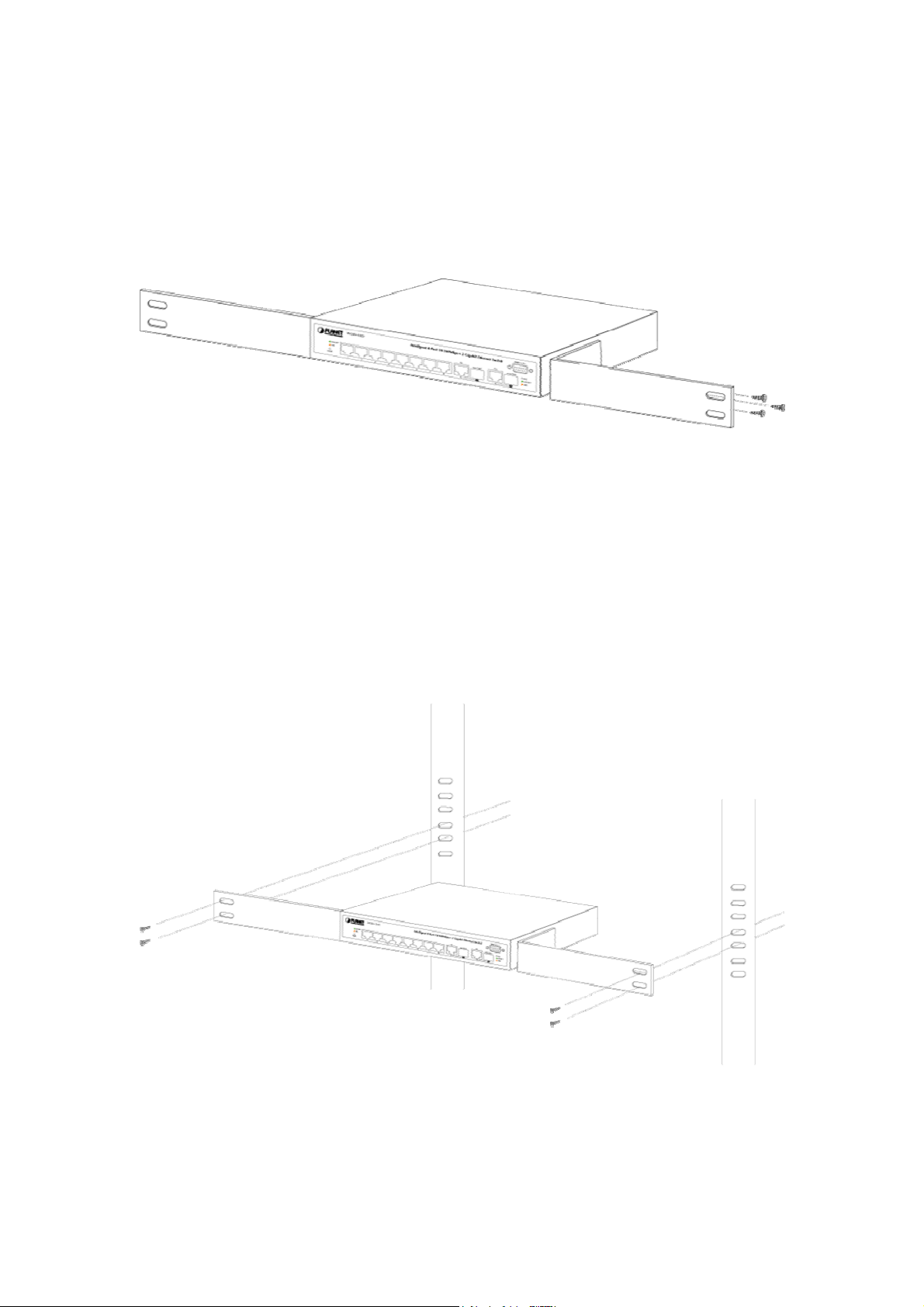
2.2.2 Rack Mounting
To install the switch in a 19-inch standard rack, please follows the instructions described below.
Step1: Place the switch on a hard flat surface, with the front panel positioned towards the front side.
St witch with supplied screws attached to the
ep2: Attach the rack-mount bracket to each side of the s
package. Figure 2-5 shows how to attach bracket
Figure 2-5 Attach brackets to the switch.
Caution:
You must use the screws supplied with the mounting brackets. Damage
in
us g incorrect screws would invalidate the warranty.
Step3
: Secure the brackets tightly.
Step4: Fo bracket to the opposite side.
Step5: After the brackets are attached to the Switch, use suitable screws to securely attach the brackets
llow the same steps to attach the second
to the rack, as shown in Figure 2-6
s to one side of the switch.
caused to the parts by
Figure 2-6 Mounting the Switch in a Rack
Step6: Proceeds with the steps 4 and steps 5 of session 2.2.1 Desktop Installation to connect the
network cabling and supply power to the switch.
Page 24
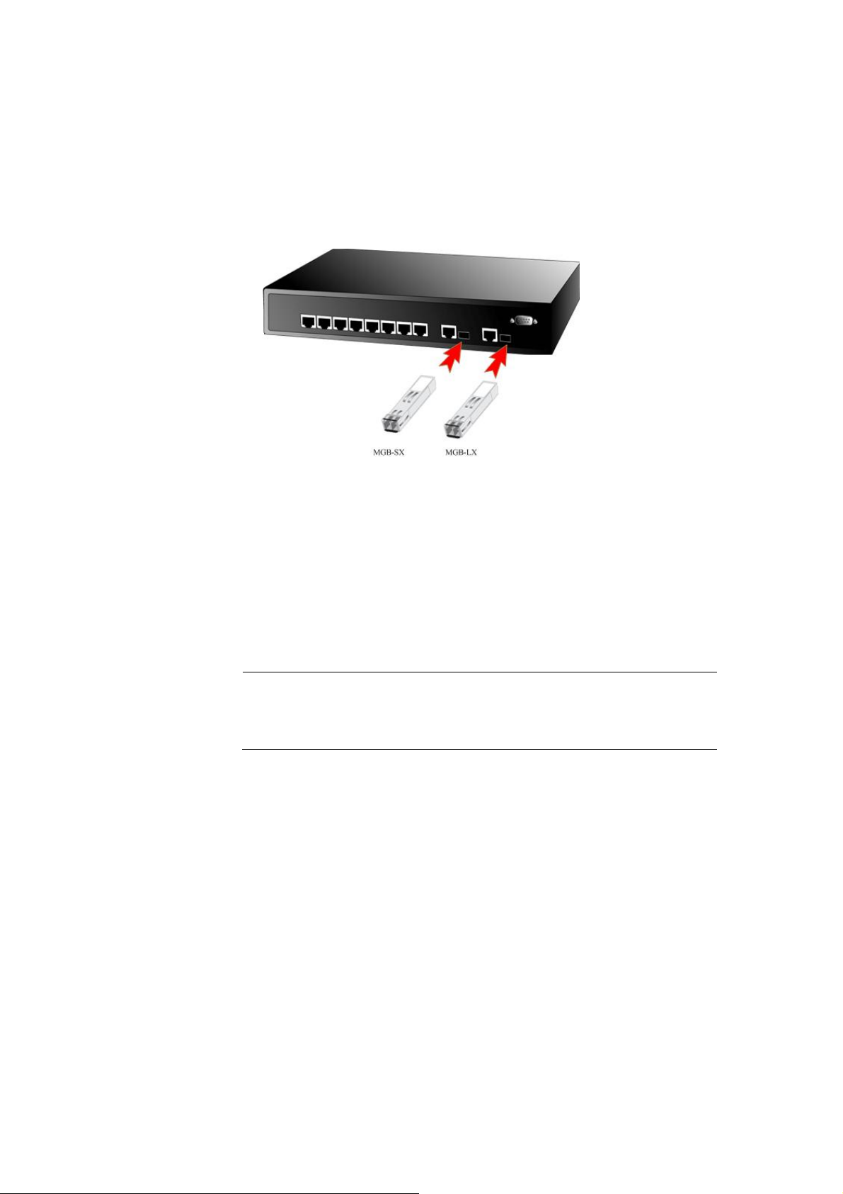
2.2.3 Installing the SFP transceiver
The sections describe how to insert an SFP transceiv
The SFP transceivers are hot-plug e and hot-swappable. You can plug-in and out the transceiver to/from
any SFP port without having to power down the Switch. As the Figure 2-7 appears.
re 2-7 Plug-in the SFP transceiver
Figu
Approved PLANET SFP Transceivers
PLANET WGSD-1022 support both single mode and multi mode SFP
er into an SFP slot.
transceiver. The following list of
approved PLANET SFP transceivers is correct at the time of publication:
■MGB-SX
■ transceiver )
MGB-LX SFP (1000BASE-LX SFP
Before connect the other switches, workstation or Media Converter.
1 sure b SFP transfer are with the same le: 1000Base-SX to
. Make oth side of the media type, for examp
1000Ba X, 1000Bas-LX to 1000Base-LX.
2. Check the fi type match the SFP transfer m
¾ To connect to multi-mode must
¾ To con 0Base-LX SFP transfer, use the single-mode fiber cable-with one side
SFP (1000BASE-SX SFP transceiver )
It recommends using PLANET SFPs on the Switc
#Note:
se-S
be mal
must be
that is not supported, the Switch will not recognize it.
ber-optic cable odel.
1000Base-SX SFP transfer, use the
e duplex LC connector type.
nect to 100
male duplex LC connector type.
h. If you insert a SFP transceiver
fiber cable- with one side
Connect the fib
1. Attach the duplex LC connector on the network cable into the SFP transceiver.
er cable
Page 25

2. Connect the device – switches
workstation or a Media Converter..
3 k the LN th iver
. Chec
is op
other end of the cable to a with SFP installed, fiber NIC on a
erating
K/ACT LED of the SFP slot on the front of
correctly.
e Switch. Ensure that the SFP transce
4. Check the Link mode of the SFP port if the link failed. Co w
Converters, set the Link mode to “1000 Force” is needed.
orks with some fiber-NICs or Media
Page 26

3. CONFIGURATION
This chapter explains the methods that you can use to configure management access to the switch
describes the types of management applicati
deliver data between your management device (work-station or personal computer) and the system. It
ontains information about port connection options.
also c
This chapter covers the following topics:
Management Access Overview
Key Concepts
Key Guidelines for Implementation
Administration Console Access
Web Management Access
SNMP Access
Standards, Protocols, and Related Reading
.1 Management Access Overview
3
he switch gives you the flexibility to access and manage the switch using any or all of the following
T
ethods:
m
ons and the communication and management protocols that
. It
An administration console
ecure
ace
nterface support are embedded in the switch software and
indows 95/98/NT/2000/ME/XP
‧Must be near switch or use dia
connection
‧Not convenient for remote users
‧Modem connection may prove to be
unreliable or slow
y can be compromised
(hackers need only know the IP address
and subnet mask)
l-up
Web browser interf
An external SNMP-based network management application
The administration console and Web browser i
are avail agement methods has their own advantages. Table
3-1 comp
able for immediate use. Each of these man
ares the three management methods.
Method Advantages Disadvantages
Console
Web
Browser
‧No IP address or subnet needed
‧Text-based
‧Telnet functionality and HyperTerminal
built into W
operating systems
‧S
‧Ideal for configuring the switch remotely ‧Securit
‧Compatible with all popular browsers
‧Can be accessed from any location
Page 27
‧Most visually appealing ‧May encounter lag times on poor
connections
SNMP
Agent
‧Communicates with switch functions at
the MIB level
‧Based on open standards
Table 3-1 Management Methods Comparison
‧Requires SNMP manager software
‧Least visually appealing of all three
methods
‧Some settings require calculations
‧Security can be compromised
(hackers need only know the
community name)
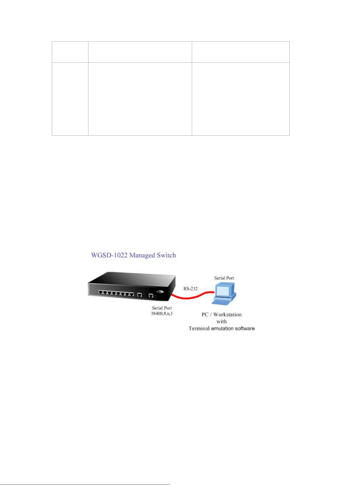
3.1.1 Administration Console
The administration console is an internal, character-oriented, and command line user interface for
performing system administration such as displaying statistics or changing option settings. Using this
method, you can view the administration console from a terminal, personal computer, Apple Macintosh,
or workstation connected to the switch's console (serial) port.
There are two ways to use this management method: via direct access or modem port access. The
following sections describe these methods. For more information about using the console, refer to
Chapter
5 Command Line Interface Console Management.
3.1.2 Direct Access
Direct access to the administration console is achieved by directly connecting a terminal or a PC
equipped with a terminal-emulation program (such as HyperTerminal) to the switch console (serial) port.
When using this management method, a null-modem cable is required to connect the switch to the PC.
After making this connection, configure the terminal-emulation program to use the following parameters:
The default parameters are:
384,00 bps
8 data bits
Page 28

No parity
1 stop bit
You can change these settings, if desired, after yo
because you can remain connected and monitor the system during system reboots. Also, certain error
messages are sent to the serial port, regardless of the interface through which the associated action was
initiated. A Macintosh or PC attachment can use any terminal-emulation program for connecting to the
terminal serial port. A workstation attachment under UNIX can use an emulator such as TIP.
u log on. This management method is often preferred
3.2 Web Management
The switch provides a browser interface
you set up your IP address for the switch, you can access the switch's Web interface applications directly
in your Web browser by entering the IP address of the switch. You can then use your Web browser to list
and manage switch configuration parameters from one central location, just as if you were directly
connected to the switch's console port.
Web Management requires either Microsoft Internet Explorer 4.01 or later or Netscape Navigator 4.03 or
later.
that lets you configure and manage the switch remotely. After
3.3 SNMP-Based Network Management
You can use an external SNMP-based application to configure and manage the switch. This
mana e SNMP Network Management
gement method requires the SNMP agent on the switch and th
Stati unity string. This management method, in fact, uses two community strings:
on to use the same comm
the get community string and the set community string. If the SNMP Net-work management Station only
w
kno s the set community string, it can read and write to the MIBs. However, if it only knows the get
comm t can only read MIBs. The default gets and sets community strings for the switch are
unity string, i
publ
ic.
3.4 Protocols
The switch supports the following protocols:
Virtual terminal protocols, such as Telnet
Simple Network Management Protocol (SNMP)
3.4.1 Virtual Terminal Protocols
A virtual terminal protocol is a software program, such as Telnet, that allows you to establish a
management session from a Macintosh, a PC, or a UNIX workstation. Because Telnet runs over TCP/IP,
Page 29

you must have at least one IP address configured on the switch before you can establish access to it with
a virtual terminal protocol.
Terminal emulation differs from a virtual terminal protocol in that you must connect a
#Note:
terminal directly to the console (serial) port.
3.4.2 SNMP Protocol
Simple Network Management Protocol (SNMP) is the standard management protocol for multi-vendor IP
networks. SNMP supports transaction-based queries that allow the protocol to format messages and to
transmit information between reporting devices and data-collection programs. SNMP runs on top of the
User Datagram Protocol (UDP), offering a connectionless-mode service.
3.4.3 Managemen
ll of the management application modules use the same Messaging Application Programming Interface
A
(MAPI). By unifying management methods with a single MAPI, configuration parameters set using one
method (console port, for exa
example, SNMP agent of Web browser).
The man gement architecture of the switch adheres to the IEEE open standard. This complia
assures customers that the switch is compatible with, and will interoperate with other solutions that
dhere to the same open standard.
a
a nce
t Architecture
mple) are immediately displayable by the other management methods (for
Page 30

4. Web Configuration
The W configured through an Ethernet connection, make sure the manager PC must
GSD-1022 can be
be se net address with the switch. For example, if you have changed the default IP
t on same the IP sub
addre 68.1.1 with subnet mask 255.255.255.0 via console, then the manager PC
ss of the Switch to 192.1
shoul 8.1.x (where x is a number between 1 and 253) with subnet mask 255.255.255.0.
d be set at 192.16
Or you ca actory default IP address 192.168.1.254 to do the relative configuration on manager
PC. T s Figure 4-1 appears.
Logging on the switch
1. lorer 5.0 or above Web browser. Enter the factory-default IP address to access the
2. When the following login screen appears, the system will ask you to enter the username and
n use the f
he ceen in
Figure 4-1 Web Management via ethernet
Use Internet Exp
b ry-default IP Address as following:
We interface. The facto
h 8.1.254
ttp://192.16
password.
Default User name: admin
Default Password: admin
The login screen in Figure 4-2 appears.
Page 31

3. After entering t e and password, the main screen appears as Figure 4-3. he usernam
Figure 4-2 WGSD-1022 Web Login screen
Figure 4-3 Web Main Screen of WGSD-1022
Now, you can use the Web management interface to continue the switch management or manage the
switch by console interface.
#Note:
It is recommended to use Internet Explore 6.0 or above to access WGSD-1022.
Page 32

4.1 Main Screen
The Switch provides a Web-based browser interface for configuring and managing the Switch. This
interface allows you to access the switch using the Web browser of your choice. This chapter describes
how to use the switch’s Web browser interface to con-figure and manage the switch.
Description
Via the We the administrator can setup the WGSD-1022 by select the functions those
Main Functions Menu Sub Menu
Port Link Status
Figure 4-1
Save Config
b-Management,
Main Screen
listed in the Main Function. The screen in Figure 4-2 appears.
Figu
re 4-2 WGSD-1022 Main Funcrions Menu
The follow
ing functions can be configured here:
Setup
Port Config
VLAN Config
Statistics
ACL
Security
QoS
Spanning Tree
Multicast
Page 33

SNMP
Admin
4.2 S
The Setup menus include the tree
4.2.1 Summ
The summary screen provides Device and System Information about the Switch.
etup
Summary
Network Settings
Time
ary
sub-menus:
The page contains the fol in
rmation
Device Info
• System Name
• IP Address
• Subnet Mask
• DNS Servers
lowing
Figure 4-3 System Summary screen
formations:
Display your system name
Display the current IP address of the device
Display the subnet mask se
Display the current DNS Servers, no matter by manual setting or
assigned by the DHCP server
tting of the device
Page 34

• Default Gateway
Display the current default gateway setting
• Address Mode
• Base MAC Address
System Information
• Serial Number
• Model Name
• Hardw
• Boot Version
• Firmware Version
• System Location
are Version
Show the IP Address mode of the system – By Static or Dynamic
(DHCP)
T
he MAC address of the Switch displays here
The unique box serial number for this switch
The product name of this sw
The release version maintenance number of the hardware
The version of boot system currently running on the switch
The opera
Display where the Switch is locate
ting system currently running on the switch
itch
d
• System Contact
• m Up Time
Syste
• Current Time
4.2.2 Network Settings
The Basic Setup Table include the Netw h allows you to assign DHCP or
static IP settings to interfaces and ass
In the Networking Setting screen, you c
Display the administrative contact person
The time in days, hours and minutes since the last switch r
Specifies the time and date. The format is hour, minute, second,
month, day, year
eboot
ork Settings (see figure 4-3), whic
ign default gateways.
an set these parts as below:
Page 35

he page includes the following fields:
T
Figure 4-4 Network Setting screen
Iden fication:
IP Configuration:
ti
• Syste
• System Location
• System Contact
• System Object ID
• Base MAC Address
• Management VLAN
• IP Address Mode
m Name
Type your system name
Type where the Switch is located
Enter the administrative contact person
Tthe system object identifier is in this field
The MAC a
Where you can select the Management VLAN.
The default Managemanet VLAN is VLAN 1
Where select Static or Dynamic IP address configuration.
The Default Mode is Static
ddress of the Switch displays here
• Host Name
In this field you can enter the DHCP Host Name
Page 36

• IP Address
Enter the IP address when you want to use a static address.
The default IP Address is 192.168.1.254
• Subnet Mask
• Deafault Gateway
• DNS Server
Enter the IP subnet mask for the interface.
The factory default value is 255.255.255.0
Enter the default gateway for the IP interface.
The factory default value is 0.0.0.0
Enter the IP Address of the DNS Server. The Domain Name System
(DNS) converts user-defined domain names into IP addresses.
4.2.3 Time
In the Basic Setup Table, you can se , by which you can configure the
time settings for the Switch.
You can select SNTP Servers: Server1 for the primary SNTP server and Server2 for the secondary SNTP
server.
e the Time Setup (see figure 4-5)
Figure 4-5 Time screen
The Time page includes the follow
Set Time
• Use System Time
ing fields:
Specifies that the system time is not set b
y an external source but the
Page 37

Local time settings.
• Use SNTP Time
Local
Time
• Hours / Minu
Seconds
• Month / Day / Year
• Time Zone
Daylight Saving
• Daylight Saving
ntes /
Specifies that the system time
Defines the system time. The field format is HH:MM:SS, for exam
21:15:03.
Defines the system date. The field format is Day:Month:Year, for
example, 04 May 2050.
The difference between Greenwich Mean Time (GMT) and local time.
For example, the Time Zone Offset for Paris is GMT +1, while the
local time in Taipei is GTM +8.
Enables the Daylight Savings Time (DST) o
devices location. The possible field values are:
• USA -- The device s
of April, and reverts t
Sunday of October.
• European -- The device switc
Sunday in March and reverts to standard time at 1:00 am on the
last Sunday in October. The European option appl
members, and other European countries using the EU standard.
• Other -- The DS
device locality. If Other is selected, the From and To fie
be defined.
T definitions are user-defined based on the
is set via an SNTP server
ple,
n the device based on the
witches to DST at 2 a.m. on the first Sunday
o standard time at 2 a.m. on the last
hes to DST at 1:00 am on the last
ies to EU
lds must
• Time Set Offset
• From
• To
For non USA and European countries, the amount of time
can be set in minutes. The value range is (1-144
The default time is 60 minutes.
Defines the time that DST begins in countries other than USA or
Europe, in
For example, DST begins on the 25th October 2007 5:00 am, the two
fields will be 25Oct07 and 5:00. The possible fie
• Date -- The date at which DST
• Month -- The month of the year in which D
• Year-- The year in which th
• Time -- The time at which DST begins. The field format is
Defines the time that DST ends in countries other than USA or
European in the format DayMonthYear in one field and time in
another. For example, DST ends on the 23rd March 2008 12:00 am,
the two fields will be 23Mar08 and 12:00. The possible field values
the format DayMonthYear in one field and time in another.
begins. The possible field range
is 1-31.
possible field range is Jan-Dec.
e configured DST begins.
Hour:Minute, for example, 05:3
0.
0).
ld values are:
ST begins. The
for DST
Page 38

• Recurring
• From
are:
• Date -- The date at which DST ends. The possible field range is
1-31.
• Month -- The month of the year in which DST ends. The
possible field range is Jan-Dec.
• Year-- The year in which the configured DST ends.
• Tim
e -- The time at which DST starts. The field format is
Hour:Minute, for examp
D
efines the time that DST starts in countries other than USA or
E
urope where the DST is constant year to year. The possible field
va
lues are:
efines the time that DST begins each year. For example, DST
D
be y second Sunday in April at 5:00 am. The possible
gins locally ever
fie
ld values are:
• Day -- The d
ay of the week from which DST begins every year.
le, 05:30.
The possible field range is Sunday-Saturday.
• Week -- The week w
ithin the month from which DST begins
every year. The possible field range is 1-5.
• Month -- The
month of the year in which DST begins every year.
The possible field range is Jan.-Dec.
• Time -- The time at which DST begins every year. The field
format is Hour:Min
ute, for example, 02:10.
• To
Defines the recurring time that DST ends each year. For example,
DST ends locally every fourth Friday in October at 5:00 am. The
possible fi
eld values are:
• Day -- The day of the week at which DST ends every year. The
possible field range is Sunday-Saturday.
• Week -- The week within the month at which DST ends every
year. The possible field range is 1-5.
• Month --
The p
The month of the year in which DST ends every year.
ossible field range is Jan.-Dec.
• Time -- The time at which DST ends every year. The field format
is Hour:Minute, for example, 05:30.
SNTP Server
• Server1
Enter a user-defined SNTP server IP addresses or hostname. Up to
twot SNTP ser
vers can be defined.
The primary server provides SNTP information.
• Server2
• Poll Interval
(60-86400)
The backup server provides SNTP information.
efines the interval (in seconds) at which the SNTP server is po
D lled
for Unicast information.
#Note:
The device supp
accurate network ynchronization up to the millisecond. Time
orts the Simple Network Time Protocol (SNTP). SNTP assures
device clock time s
synchronization is performed by a network SNTP server. SNTP operates only as a
Page 39

client, and cannot provide time services to other systems.
4.3 Port Configuration
In this field, you can see these parts, such as port settings, Link aggregation, LACP.
4.3.1 Port settings
To use the port settings screen for setting up each of the switch’s ports.
It shows these parts: port, description, admin status, link status, speed, duplex,
MDI/MDIX, Flow control, type, LAG, PVE (see Figure 4-6):
The Port ains
Settings screen cont the following fields:
• Port
• Description
• Admin
• Link Sta
Status
tus
Figure 4-6 Port Settings screen
Shows the port number. You can click on the Detail button of the
appropriate port (G1, G2) to use an SFP
button shows the Port Configuration Detail screen, which include port,
description, port type, admin status, current port status ……
Click up the Detail button to make a brief descriptio
When to choose the UP button, the port can be accessed norma
choose the Down button, the port will be taken offline
Shows an active connection when you choose the UP button, there is
no active connection or the port has been taken offline by an
module, and the Detail
n of the port
lly, to
Page 40

Admiinistrator when you choose the Down button
• Speed
• Duplex
• MDI/ MDIX
• Flow co
• Ty pe
• LAG
ntrol
Shows the connection speed of the port and the speed can be
configured only when auto-negotiation is disabled on that port
The port duplex mode, Full (transmission occurs
simultaneously) or Half (transmission occurs in only one direction at a
time). This mode can be
disabled and port speed is set to 10Mbps or 100Mbps.
It cannot be
Shows the MDI/MDIX status of the port. To use the MDI setting if the
port is
is connected to a hub or another switch
Shows the flow control status of the port. It is active when the port
uses Full Duplex Mode
Shows th
Shows whether the port is part of a LAG
configured on Link Aggregation Groups (LAGs)
connected to an end station. To use the MDIX setting if the port
e port type
configured only when auto-negotiation is
in both directions
• PVE
• Detail
Click the Detail button for more detail port configuration.
Port Configuration Detail screen (see figure 4-7)
It bypasses
multicast, and broadcast traffic to an uplink w
VLAN Edge (PVE) port, Uplinks can be ports or LAGs.
It will open the port configuration detail screen
the Forwarding Database and forwards all unicast,
hen a port is a Private
Page 41

Figure 4-7 Per Port Configuration detail screen
The Port Configuration screen contains the following fields:
• Port Indicates the number of the port
• Description Where can be entered by clicking on the Detail button
• Port Type This is the port type
• Admin Status The port can be taken offline by selecting the Down option.
When Up is selected, the port can be accessed normally.
• Current Port Status The current status of the port is displayed here
• Reactivate If you want to reactivate a port that has been suspended, click the
Suspended Port checkbox
• Operational Status This indicates whether or not the port is active
• Admin Speed Change the speed of the port here
• Current Port Speed The current speed of the port is displayed here
Page 42

• Admin Duplex Change the duplex mode here
• Current Duplex
Mode
• Auto Negotiation You can enable or disable the port’s Auto Negotiation feature. If using
• C
urrent Auto
Nego
tiation
• Admin
Advertisement
Tthis is the duplex mode of the port
an SFP module, Auto Negotiation for th
disable
This is the current settin ’s Auto Negotiation feature
Specifies the capabilitie by the port. Multi
ay be selected or
m Max Capability ca of the
ns.
optio
The available options are:
Max Capability, which indicates that the port speeds and duple
mode settings can be accepted.
10 Half, indicates that the port is advertising a 10Mbps half duplex
mode setting.
10 Full, indicates that the port is advertising a 10Mbps full duplex
mode setting.
100 Half, indicates that the port is advertising a 100Mbps half
duplex mode setting.
g of the port
s to be advertised ple options
e specific port should be set to
n be selected to cover all
x
100 Full, indicates that the port is advertising a 100Mbps full duplex
mode setting.
1000 Full, indicates that the port is advertising a 1000Mbps full
duplex mode setting
• Current
Advertisement
• Neighbor
Advertisement
• Back Pressure The Back Pressure feature of the selected port can be enabled or
• Current Back
Pressure
• Flow Control The Flow Control feature of the selected port can be enabled or
• Current Flow Displ
Control
The port advertises its capabilities to its neighbor port to begin the
negotiation process. This field displays the current advertisement
settings.
Tthe neighbor port (the port to which the selected interface is
connected) advertises its capabilities to the port to start the
negotiation process. This field displays the neighbor’s current settings
disabled
Displays whether Back Pressure is enabled or disabled on the
currently selected port
disabled
ays whether Flow Control is enabled or disabled on the currently
selected port
• MDI/ MDIX
• Auto - the port to automatically detect the cable type.
• MDI - if the port is connected to an end station.
• MDIX
- if the port is connected to a hub or another switch
Page 43

• Current MDI/MDIX
This is the current MDI/MDIX status of the port
• PVE ernet switches ONLY. When a port is a Private VLAN
Click the Save Settings button to save your changes.
For Gigabit Eth
Edge (PVE) port, it bypasses the Forwarding
all unicast, multicast, and broadcast traffic to an upl
be ports or LAGs.
Database and forwards
ink. Uplinks can
4.3.2 Link Aggregation
When you enter the Link Aggregation, you can see these parts (see figure 4-8), such as:
LAG, shows whether the port is part of a LAG.
The Link Aggregation page contains
• LAG In
• Description Indic
• Administrative Up i ows administrator
Status
• Ty pe The the LAG.
• Link Status Sho when you choose the UP button, there is
Figure 4-8 Link Aggregation screen
the following fields:
dicates the number of the LAG interface. Up to eight LAG interface
can
be configured.
ates the description of the LAG ports
ndicates that the port is available and down sh
has taken the port offline. You can click the Save Setting
save this option.
port types that comprise
ws an active connection
no active connection or the port has been taken offline by an
Admiinistrator when you choose the Down button
s option to
Page 44

• Speed e connection speed of the port and the speed can be
Shows th
configured only when auto-negotiation is disabled on that port
• Duplex directions
• Flow control Shows the flow control status of the port. It is active when the port
• e
LAG Mode Shows the current mode of the LAG interfac
Click the D on for more det n.
Linkl A tion deta
t per-LAG detail configuration page, the administrator can select ports to be the members of the LAG
A
terface. The scree appears as follow:
in
etail butt ail port configuratio
ggrega il configuration
The port duplex mode, Full (transmission occurs in both
simultaneously) or Half (transmission occurs in only one direction at a
time). This mode can be configured only when au
disabled and port speed is set to 10Mbps or 100Mbps.
uses
Full Duplex Mode
to-negotiation is
Page 45

4.3.3 LACP
Aggregated Links can be manually setu
Link Aggr ntrol Protocol
Aggregat be linked into
the same speed, set to full-duplex
The LACP screen contains fields f CP LAG s (see figure 4-9)
egation Co (LACP).
e ports can link-aggregation port-groups. Each group is comprised of ports with
p or automatically established on the relevant links by enabling
operation.
or configuring LA
Figure 4-9 LACP configuration screen
The page contains the following fields:
• LACP System
Priority
• Port
• LACP Port Priority
• LACP Timeout
• Admin Key
Indicates the global LACP priority value. The possible range is 1655
Set the port number which need to timeout and the priority values are
assigned
Where set the LACP priority value for the port and the field range is
1-65535
A
dministrative LACP timeout. A short or long timeout value can be
sele
A chann
k
ey, in other words, this only applies to ports located on the same
swit
35 and the default value is 1.
cted. Long is the default
el will only be formed between ports having the same admin
ch.
Page 46

4.4 VLAN Configura
tion
A Virtual a logical n llows you to
isolate net y mem e traffic from the same VLAN members.
Basically, creating a VLAN from a switch is logically equivalent of reconnecting a group of network
devices t r Layer 2 switch
physically.
The WGSD-1022 supports 802.1Q (tagged-based) and GVRP Dynamic VLAN setting in web
manageme ault configuration, VLAN support is “802.1Q”.
IEEE 802.1Q VLANs
IEEE 802.1Q (tagged) VLAN are implemented on the Switch. 802.1Q VLAN require tagging, which
enables them to span the entire network (assuming all switches on the network are IEEE
802.1Q-compliant).
VLAN allow a network to be segmented in order to reduce the size of broadcast domains. All packets
entering a VLAN will only be forwarded to the stations (over IEEE 802.1Q enabled switches) that are
members of that VLAN, and this includes broadcast, multicast and unicast packets from unknown
sources.
LAN (VLAN) is etwork grouping that limits the broadcast domain. It a
work traffic so onl bers of the VLAN receiv
o anothe . However, all the network devices are still plug into the same switch
nt page. In the def
VLAN can also provide a level of security to your network. IEEE 802.1Q VLAN will only deliver packets
between stations that are members of the VLAN. Any port can be configured as either tagging or
untagging. The untagging feature of IEEE 802.1Q VLAN allows VLAN to work with legacy switches that
don't recognize VLAN tags in packet headers. The tagging feature allows VLAN to span multiple
802.1Q-compliant switches through a single physical connection and allows Spanning Tree to be enabled
on all ports and work normally.
Any port can be configured as either tagging or untagging. The untagging feature of IEEE 802.1Q VLAN
allows VLAN to work
feature allows VLAN to span multiple 802.1Q-compliant switches through a single physical connection
and allows Spanning Tree to be enabled on all ports and work normally.
Frame Leave
Leave port is tagged Frame remains tagged Tag is inserted
Leave port is untagged Tag is removed Frame remain untagged
with legacy switches that don’t recognize VLAN tags in packet headers. The tagging
Frame Income
Income Frame is tagged Income Frame is untagged
In this field, there are five items, such as Create VLAN, Port setting, Ports to VLAN, VLAN to Ports,
GVRP…
Page 47

4.4.1 Create VLAN
In this table, the informati nd gl with VLAN s will be
provided (see figure 4-10).
on a obal parameters for configuring and working
Figure 4-10 Create VLAN screen
The page contains the following fields:
Single VLAN
• VLAN ID (2-4094)
• VLAN Name
• VLAN Range
VLAN Table
The VLAN Table displays a list of all configured VLANs, include the
• VLAN ID,
• VLAN Name,
You can configure the ID number of the VLAN by this item. Up to 256
VLANs can be created. This field is used to add VLANs one at a time.
If you want to add the defined VLAN ID number, you can press the
Add button.
Where shows the user-defined VLAN name
Indicates a range of VLANs configured. To add the defined range of
VLAN ID numbers, press the Add Range button
• Status
To remove a VLAN, click the Remove button.
Page 48

4.4.2 Port setting
In this port setting screen (refer to figure 4-11), the parameters managing ports that are part of a VLAN
n set the default VLAN ID (PVID). All untagged packets arriving to the device will be provided, and you ca
are tagged by the ports PVID.
Figure 4-11 VLAN Port Setting screen
The page contains the following fields:
• Port Displays the port number included in the VLAN
• Mode es are:
• Acceptable Frame
Typ e
Indicates the port mode. Possible valu
• General - The port belongs to VLANs, and each VLAN is
• Access - The port belongs to a single untagged VLAN. When a
• Trunk - The port belongs to VLANs in which all ports are tag
P ccepted on the port. Possible values are:
acket type a
• Admit Tag Only - indicates that only tagged packets are
efined as tagged or untagged (full 802.1Q mode).
user-d
port is in Access mode, the packet types which are accepted on
the port (pack
possible to enable/ disable ingress filtering on an access port.
(except for
accepted on the port.
et type) cannot be designated. It is also not
ged
an optional single native VLAN).
• Admit All - indicates that both tagged and
accepted on the port.
• PVID A to
ssigns a VLAN ID to untagged packets. The possible values are 2
409 ned as per standard and industry practice as
4. VLAN 4095 is defi
the discard VLAN. Packets classified to the Discard VLAN are
untagged packets are
Page 49

dro
pped
• Ingress Filtering E
• LAG Indicates the LAG to which the VLAN is defined
Port Mode VLAN Membership Frame Leave
Access Belo
Allow o multiple untagged
General
VLANs at the same time
Allow
Trunk
VLAN (Tag=PVID or Original VID be remained)
4.4.3 Ports to VLAN
nables or disables Ingress filtering on the port. Ingress filtering
dis do not include an ingress port
cards packets which
ngs to a single untagged VLAN
( Tag=PVID be remo
ed to belongs t
ed to belongs to multiple Tagged
s at the same time
Untagged
Untagged
(Tag=PVID be removed)
Tagged
ved)
The Ports to VLAN screen contain ID
(PVID) is configure e VLAN screen. All untagged packets arriving to the device are tagged
by the ports PVID. The Ports to VL h port.
Ports are assigned VLAN membership by selecting and configuring the presented configuration options,
you can
refer to figure 4-12.
d on the Creat
s fields for configuring ports to a VLAN. The port default VLAN
AN screen contains a Port Table for VLAN parameters for eac
Figure 4-12 Ports to VLAN screen
Page 50

The page contains the following fi
elds:
• VLAN
• Access
• Trunk
• General
• Tagged
• Untagged
• Forbidden
• Exclude
Where means the VLAN number
Indicates the port belongs to a single untagged VLAN. When a port is
Access mode, the packet types which are accepted on the port
in
cannot be designated. Ingress filtering cannot be enabled/disabled on
an access port.
Which indicates the port bel
tagged, except for one port that can be untagged
Which indicates the port belongs to VLANs, and each VLAN is
user-defined as tagge
Defines the interface as a tagged member of a VLAN. All packets
forwarded by the interface are tagged.
information
ets forwarded by the interface are untagged
Pack
Forbidden ports are not included in the VLAN
Excludes the interface from the VLAN. However, the interface can b
added to the VLAN through GV
ongs to VLANs in which all ports are
d or untagged (full 802.1Q mode)
The packets contain VLAN
e
RP
4.4.4 s
The VLAN to Ports screen (see figure 4-13) contains fields for configuring VLANs to a port. This screen
displays these parts, such as:
VLAN to Port
Figure 4-13 VLA N to Ports
Page 51

The page contains the following fields:
• Port
• Mode
• Join VLAN
• VLANs
• LAG
Displays the interface number
By which indicates the port to VLAN mode. Possible field values are:
• General - By which indicates the port belongs to VLANs, and
each VLAN is user-defined as tagged or untagged (full 802.1Q
mode).
• Access - Indicates the port belongs to a single untagged VLAN.
When a port is in Access mode, the packet types which are
accepted on the port cannot be designated. Ingress filtering
cannot be enabled/disabled on an access port.
• Trunk - Which indicates these ports belong to VLANs in which all
ports are tagged, except for one port that can be untagged.
Defines the VLANs to which the interface is joined.
Displays the PVID tag
Indicates whether the port is a member of a LAG. If it is a member of a
LAG, it cannot be configured to a VLAN. The LAG to which belongs
can be configured to a VLAN
Press the “Join VLAN” button to selecet and add VLAN to per port. The screen in Figure 4-14 appears.
igure 4-14 Join VLAN to Port screen F
4.4.5 GVRP
GARP VL co AN AN Registration Proto l (GVRP) is specifically provided for automatic distribution of VL
Page 52

membership information among V
LAN-aware bridges. GVRP allows VLAN-aware bridges to
automatic Ns to bridge ports mapping, without having to individually configure each bridge
and register VLAN membership.
The Global System LAG informati rts, but represent the
LAG GVRP
The GVRP screen (refer to 4-15) i s
for both areas are the same.
ally learn VLA
on displays the same field information as the po
information.
s divided into two areas, GVRP and GVRP Table. The field definition
F tion screen
igure 4-15 GVRP configura
The page contains the following field
• Enable GVRP
• Interface
• GVRP State
•
Dynamic VLAN
Creation
• GVRP Registration
Enables and disables GVRP on the
Displays the interface on which GVRP is enabled. Possible field
values are:
Port - indicates the port number on which GVRP is enabled.
When the checkbox is checked, GVRP is enabled on the interface
When the checkbox is checked, Dynamic VLAN creation is enabled
on the interface
When the checkbox is checked, VLAN registration thro
s:
device
AG - indicates the LAG numberL on which GVRP is enabled.
ugh GVRP is
Page 53

enabled on the device..
• Update
The Update button adds the
e bottom of the screen
th
configured GVRP setting to the table at
Page 54

4.5 Statistics
The Statistic of the switch
This field includes these parts as below:
4.5.1 RMON Statistic
The RMON Statistics screen (refer to figure 4-16) contains fields for viewing information about device
utilization and errors that occurred on the device.
The page contains the following fi
• Interface
• Refresh Rate
Figure 4-16 RMON Statistics screen
elds:
Indicates the device for which statistics are d
field values are:
• Port - defines the specific port for which RMO
displayed.
• N statistics are
LAG - defines the specific LAG for which RMO
displayed.
D
efines the amount of time that passes before the interface statistics
ar
e refreshed. The possible field values are:
• No Refresh, indicates that the RMON statistics are not refreshed.
• 15 Sec, which indicates that the RMON statistics are refreshed
every 15 seconds.
• 30 Sec, which indicates that the RMON statistics are refreshed
isplayed. The possible
N statistics are
Page 55

every 30 seconds.
• Drop Events
• Received Bytes
(Octets)
• Received Packets
• Broadcast Packets
Received
• Multicast Packets
Received
• CRC & Align Errors
• 60 Sec, which indicates t
every 60 seconds.
which displays the number of dropped events that have occurred on
the interface since the device was last refreshed
Displays the number of octets received on
device was last refreshed. This number includes bad packets and
FCS octets, but excludes framing bits
Displays the number of packets receiv
bad packets, Multicast and broadcast packets, since the device was
last refreshed
Which displays the number of good broadcast packets received on
the interface since the device was last refreshed. This number does
not include Multicast packets
Displays the number of good Multicast packets received on the
interface since the device was last refreshed
which displays the number of CRC and Align errors that have
occurred on the interface since the device was last refreshed
hat the RMON statistics are refreshed
the interface since the
ed on the interface, including
• Undersize Packets
• Oversize Packets
• Fragments
• Jabbers
• Collisions
• Frames of xx Bytes
Displays the number of undersized packets (less than 64 octets)
received on the interface since the device was last refreshed
Displays the number of oversized packets (over 1518 octets) received
on the interface since the device was last refreshed.
Indicates the number of fragments (packets with less than 64 octets,
excluding framing bits, but including FCS octets) received on the
interface since the device was last refreshed
Indicates the total number of received packets that were longer than
1518 octets. This number excludes frame bits, but includes FCS
octets that had either a bad Frame Check Sequence (FCS) with an
integral number of octets (FCS Error) or a bad FCS with a
non-integral octet (Alignment Error) number. The field range to detect
jabbers is between 20 ms and 150 ms
Displays the number of collisions received on the interface since the
device was last refreshed
Number of xx-byte frames received on the interface since the device
was last refreshed.
Clear Counters button, this option will reset all of the statistic counts.
Page 56

Refresh Now button, which use this option to refresh the statistics.
4.5.2 RMON History
The RMON History contains information about samples of data taken from ports. For example, the
samples may include interface definitions or polling periods.
The RMON History Control screen is divided into RMON History and Log Table.
Log Table includes the following parts (see figure 4-17)
F
igure 4-17 RMON History screen
The page contains the following fields:
RMON History
• Source Interface
• Sampling Interval
Displays the interface from which the history samples were taken.
The possible field values are:
Port, specifies the port from which the RMON information was taken.
LAG, specifies the port from which the RMON information was taken.
Indicates (in seconds) the time that samplings are taken from the
ports. The field range is 1-3600.
The default is 1800 seconds (equal to 30 minutes)
Page 57

• Sampling Requested
Disp
lays the number of samples to be saved. The field range is
1-65
535.
The default value is 50
• Current Number of
Samples
• Owner
Use the A n when
bottom of the screen
RMON History Table
The RMON History screen (see figure 4-18) contains interface specific statistical network samplings.
Each table entry represents all coun
dd to List butto you add the configured RMON sampling to the Log Table at the
Displays the current number of samples taken. View History button.
This button opens the RMON History screen
Where displays the RMON station or user that requested the RMON
ation.
inform
The field range is 0-20 characters
ter values compiled during a single sample.
Figure 4-18 RMON History Table screen
• Sample No
• Received Bytes
(Octets)
Which indicates the sample number from which the statistics were
taken
Displays the number of octets received on the interface since the
device was last refreshed. This number includes bad packets and
FCS octets, but excludes framing bits
Page 58

• Received Packets
Displays the number of packets received on the interface since the
device was last refreshed, including bad packets, Multicast and
Broadcast packets
• Broadcast Packets
• Multicast Packets
• CRC Align Errors
• Undersize Packets
• Oversize Packets
• Fragments
• Jabbers
Displays the number of good Broadcast packets received on the
interface since the device was last refreshed. This number does not
include Multicast packets
Displays the number of good Multicast packets received on the
interface since the device was last refreshed
Which displays the number of CRC and Align errors that have
occurred on the interface since the device was last refreshed.
Displays the number of undersized packets (less than 64 octets)
received on the interface since the device was last refreshed
Displays the number of oversized packets (over 1518 octets)
received on the interface since the de
Displays the nu
excluding framing bit
interface since the device was last refreshed.
D were longer than
isplays the total number of received packets that
1 ncludes FCS
518 octets. This number excludes frame bits, but i
octet e (FCS) with an
s that had either a bad Frame Check Sequenc
integral number of octets (FCS Error) or a bad FCS with a
non-integral octet (Alignment Error) number. The field rang
jabbers is between 20 ms and 150 ms.
mber of fragments (packets with less than 64 octets,
s, but including FCS octets) received on the
vice was last refreshed
e to detect
4.5.3 RMON Alarm
The RMON Alarm screen (see figure 4 or setting network alarms. Network alarms
ccur when a network problem, or event, is detected. Rising and falling thresholds generate events.
o
-19) contains fields f
Page 59

Figure 4-19 RMON Alarm screen
The page contains the following fields:
• larm Entry
• Source Interface
• Counter Name
• Sample Type
• Rising Threshold
Indicates a specific alarm
Displays the interface for which RMON statistics are displayed. The
possible field values are:
• Port, displays the selected port of the RMON statistics.
• LAG, displays the RMON statistics for the selected LAG.
Displays the selected MIB variable
Defines the sampling method for the selected variable and comparing
the value against the thresholds. The possible field values are:
• Absolute, compares the values directly with the thresholds at the
end of the sampling interval.
• Delta, subtracts the last sampled value from the current value. The
difference in the values is compared to the threshold.
Displays the rising counter value that triggers the rising threshold
alarm. The rising threshold is presented on top of the graph bars.
Each monitored variable is designated a color
Page 60

• Rising Event
Displays the mechanism in which the alarms are reported. The
possible field values are:
• LOG. Indicates there is not a saving mechanism for either the
device or in the management system. If the device is not reset, the
entry remains in the Log Table.
• Falling Threshold
• Falling Event
• TRAP, indicates that an SNMP trap is generated, and sent via the
Trap mechanism. The Trap can also be saved using the Trap
mechanism.
• Both, indicates that both the Log and Trap mechanism are used to
report alarms.
Displays the falling counter value that triggers the falling threshold
alarm. The falling threshold is graphically presented on top of the
graph bars. Each monitored variable is designated a color.
Displays the mechanism in which the alarms are reported. The
possible field values are:
• LOG
• TRAP, indicates that a SNMP trap is generated, and sent via the
• Both, indicates that both the Log an
, indicates there is not a saving mechanism for either the
device or in the management system. If the device is not reset,
the entry remains in the Log Table.
Trap mechanism. The Trap can also be
mechanism.
to report alarms.
saved using the Trap
d Trap mechanism are used
• Startup Alarm
• Interval
• Owner
Use the Add to List button when you add the RMON Alarms Table entry.
Displays the trigger that activates the alarm generation. Rising i
defined by crossing the threshold from a low-value threshold to a
higher-value threshold
D
efines the alarm interval time in seconds
Dhere displays the device or user that defined the alarm
s
Page 61

4.5.4 RMON Events
The RMON Events screen (see figure 4-20) contains fields for defining RMON events.
The page contains the following fiel
Add Event:
• Event Entry
• Community
•
Description
• Ty pe
Figure 4-20 RMON Event screen
ds:
D
isplays the event
where displays the community to which the event belongs
Displays the user-defined event description
Describes the event type. Possible v
• None, where indicates that no ev
• Log, indicates that the event is a log entry.
• Trap, indicates that the event is a trap.
• Log and Trap, i
trap.
ndicates that the event is both a log entry and a
alues are:
ent occurred.
• Owner
Where displays the device or user that defined the event. Use the Add
to List button
Table at the bottom of the screen (see figure 4-21)
when you add the configured RMON event to the Event
Page 62

The Event Table area contains th
• Time
Press the RMON Event Log bu og or
Log and Trap, then the entries app
e following additional field:
Where displays the time that the event occurred
tton to display the log store in the flash. Only the Event type is L
ear. The screen in Figure 4-21 appears.
Figure 4-21 RMON Event Log Screen
Page 63

4.5.5 Port Utilization
The Port Utilization screen (see figure 4-22) indicates the amount of resources each interface is currently
consuming. Ports in green are functioning normally, while ports in red are currently transmitting an
excessive amount of network traffic.
Figure 4-22 Port Utilization screen
The page includes the following fields:
• Refresh Rat
e
Indicates the amount of time that passes befo
statistics are refreshed. The possible field values are:
• No Refresh - indicates that the statistics are not refreshed.
• 15 Sec - indicates that the statis
• 30 Sec - indicates that the statistics are refreshed every 30
• 60 Sec - indicates that the statistics are refreshed ev
re the port utilization
tics are refreshed every 15
seconds.
seconds.
ery 60
seconds.
Page 64

4.5.6 802.1x Statist
The 802.1X Statistic screen (see figure 4-23) contains information about EAP packets received on a
ic
specific p
ort.
Figure 4-23 802.1x Statistics screen
The page includes the following fields:
• Port
• Refresh Rate
• Name
• Description
• Packet
Indicates the port, which is polled for statistics
Indicates the amount of time that passes before the EAP statistics are
refreshed. The possible field values are:
• No Refresh, indicates that the EAP statistics are not refreshed.
• 15 Sec, which indicates that the EAP statistics are refreshed
• 30 Sec, which indicates that the EAP statistics are refreshed
• 60 Sec, which indicates that the EAP statistics are refreshed
Displays the measured 802.1x statistic
Describes the measured 802.1x statistic
Displays the amount of packets measured for the particular 802.1x
statistic
every 15 seconds.
every 30 seconds.
every 60 seconds
Page 65

4.5.7 GVRP Statistics
The GVRP Statistics screen (see figure 4-24) contains device statistics for GVRP.
The GVRP Statistics screen is divided into two areas, GVRP Statistics Table and GVRP Error
Statistics
Table.
F
igure 4-24 GVRP Statistics screen
The following fields are relevant for both
• Interface
• Refresh Rate
The GVRP Statistics Table contains the following fields:
tables:
Specifies the interface type for which the statistics are displayed
• Port,
• LAG, indicates LAG statistics are displa
In fore the GVRP statistics
dicates the amount of time that passes be
are refreshed. The possible field values are:
• No Re
• 15 Sec, which indicates that the GVRP statistics are refreshed
• 30 Sec, which indic
• 60 Sec, which indicates that the GVRP statistics are refreshed
indicates port statistics are displayed.
fresh, indicates that the GVRP statistics are not refreshed.
every 15 seconds.
every 30 seconds.
every 60 seconds.
yed.
ates that the GVRP statistics are refreshed
• Join Empty
Which displays the device GVRP Join Empty statistics
Page 66

• Empty
Displays the device GVRP Empty statistics
• Leave Empty
• Join In
• Leave In
• Leave All
The GVRP Error Statistics Table contains the following fields:
• Invalid Protocol ID
• Invalid Attribute
Typ e
• Attribute Value
By which displays the device GVRP Leave Empty statistics
By which displays the device GVRP Join In statistics
By which displays the device GVRP Leave in statistics
By which displays the device GVRP Leave all statistics
Where displays the device GVRP Invalid Protocol ID statistics
Where displays the device GVRP Invalid Attribute ID statistics. Invalid
Displays the device GVRP Invalid Attribute Value statistics. Invalid
Attribute Length, where displays the device GVRP Invalid Attribute
Length statistics
• Invalid Events
Where displays the device GVRP Invalid Events statistics. The Clear
All Counters button resets all tables
Page 67

4.6 ACL
An ACL consists of a set of rules w a packet meets
the match criteria of a rule, the sp en and the additional rules are
not check . On this m as well
as whether it applies to inbound o
ACL Rule Configuration menu.
ed for a match enu the interfaces to which an ACL applies must be specified,
hich are matched sequentially against a packet. When
ecified rule action (Permit/Deny) is tak
r outbound traffic. Rules for the ACL are specified/created using the
4.6.1 IP Based ACL
The IP Based ACL (Access Control List) screen (see figure 4-25) contains information for defining IP
Based AC
Ls.
Figure 4-25 IP-Base ACL screen
The Page contains the following fields:
• ACL Name
Displays the user-defined IP based ACLs
Page 68

• New ACL Name
Defines a new user-defined IP based ACL
• Delete ACL
• Action
• Protocol
• Select from List
By which deletes the selected ACL
Indicates the action assigned to the packet matching the ACL.
Packets are forwarded or dropped. In addition, the port can be
shutdown, a trap can be sent to the network administrator, or a packet
assigned rate limiting restrictions for forwarding. T
follows:
• Permit, by which forwards packets which meet the ACL criteria.
• Deny, which drops packets which meet the ACL criteria.
• Shutdown, where drops packet that meets the ACL criteria, and
bles the port to which the packet was addressed. Ports are
disa
reactivated from the Port Management screen.
By which creates an ACE (Access Control Event) based on a
specific protocol
Where selects from a protocols list on which ACE can be based. The
possible field values are:
• Any, matches the protocol to any protocol.
he options are as
•
TCP Flags
• EIGRP, which indicates that the Enhanced Interior Gateway
Routing Protocol (EIGRP) is used to classify network flows.
• ICMP, which in
(ICMP) is used to classify network flows.
• IGMP, which indicates that the Internet Group Management
tocol (IGMP) is used to classify network flows.
Pro
• TCP, which indicates that the Transmission Control Protocol is
used to classify network flows.
• OSPF, by which matches the
First (OSPF) protocol.
• UDP, which indicates that the User Datagram Protocol is used to
classify network flows.
• Protocol ID to Match, adds user-defined protocols to which
packets are matched to the ACE. Each proto
protocol number which is unique. The possible field range is
0-255.
This filters packets by TCP flag. Filtered packets are either forwarded
or dropped. Filtering packets by TCP flags increases packet cont
and network security. The values that can be assigned are:
dicates that the Internet Control Message Protocol
packet to the Open Shortest Path
col has a specific
rol,
• Set,
• Unset, disables filtering packets by selected flags.
• Don’t care, which indicates that selected packets do not
which enables filtering packets by selected flags.
Page 69

influence the packet filtering process.
The TCP Flags that can be selected are:
• Urg, indicates the packet is urgent.
• Ack, indicates the packet is acknowledged.
• Psh, indicates the packet is pushed.
• Rst, indicates the connection is dropped.
• Syn, indicates request to start a session.
• Fin, indicates request to close a session.
• Source Port
• Destination Port
• Source IP Address
• Wildcard Mask
Defines the TCP/UDP source port to which the ACE is matched. This
field is active only if 800/6-TCP or 800/17-UDP is selected in the
Select from List drop-down menu.
The possible field range is 0 - 65535
Defines the TCP/UDP destination port. This field is active only if
800/6-TCP or 800/17-UDP is selected in the Select from List
drop-down menu.
The possible field range is 0 - 65535
Matches the source port IP address to which packets are addressed
to the ACE
Defines the source IP address wildcard mask. Wildcard masks
specify which bits are used and which bits are ignored.
A wild card mask of 255.255.255.255 indicates that no bit is
important.
A wildcard of 0.0.0.0 indicates that all the bits are important.
For example, if the source IP address 149.36.184.198 and the
wildcard mask is 255.36.184.00, the first eight bits of the IP address
are ignored, while the last eight bits are used.
• Destination IP
Address
• Wildcard Mask
• Match DSCP
• Match IP
Precedence
Matches the destination port IP address to which packets are
addressed to the ACE
Defines the destination IP address wildcard mask
Matches the packet DSCP value to the ACE. Either the DSCP value
or the IP Precedence value is used to match packets to ACLs.
The possible field range is 0-63
Matches the packet IP Precedence value to the ACE. Either the
DSCP value or the IP Precedence value is used to match packets to
ACLs.
Page 70

The possible field range is 0-7
Use the Add to List button when you add the configured IP Based ACLs to the IP Based ACL Table at
the bottom of the screen.
4.6.2 MAC Based ACL
The MAC Based ACL screen (see figure 4-27) allows a MAC based ACL to be defined. ACEs can be
added only if the ACL is not bound to an interface.
Figure 4-26 MAC-Base ACL screen
The Page contains the following fields:
• ACL Name
•
New ACL Name
• Delete ACL
• Action
Displays the user-defined MAC based ACLs
Specifies a new user-defined MAC based ACL name.
By which deletes the selected ACL
Indic sible field values are:
• Permit, by which forwards packets which meet the ACL crite
• Deny, drops packets which meet the ACL criteria.
ates the ACL forwarding action. Pos
ria.
Page 71

• Shutdown, where drops packet that meet the ACL criteria, and
disables the port to which the packet was addressed.
• Source MAC
Address
• Wildcard Mask
• Dest. MAC Address
• VLAN ID
Matches the source MAC address to which packets are addressed to
the ACE.
Defines the source IP address wildca
specify which bits are used and ignored.
A wild card mask of 255.255.255.255 indicates that no bit is
important.
A wildcard of 0.0.0.0 indicates that all the bits are important.
For example, if the source IP address 149.36.184.198 and the
wildcard mask
are ignored, while the last eight bits are used.
Where matches the destination MAC address to w
addressed to the AC
Wildcard Mask, which defines the destination IP address wildcard
mask.
Which matches the packet’s VLAN ID to the ACE.
The possible field values are 2 to 4094.
is 255.36.184.00, the first eight bits of the IP address
E.
rd mask. Wildcard masks
hich packets are
• Ether Type
Use the “Add to List” button to L Table at
the bottom of the screen.
Where specifies the packet’s
add the configured MAC Based ACLs to the MAC Based AC
Ethernet type.
Page 72

4.7 Security
This section is to control the security access of the switch, includes the user access and management
control.
The Security function contains links to the following topics:
• ACL Binding
• RADIUS
• TACACS+
• 802.1x Settings
• Port Security
• Multiple Hosts
• Storm Control
4.7.1 ACL Binding
When an ACL is bound to an interface, all the ACE (Access Control Event) rules that have been defined
are applied to the selected interface. Whenever an ACL is assigned on a port, LAG or, VLAN, flows from
that ingress interface that do not match the ACL are matched to the default rule, which is Drop
unmatched packets. You can refer to figure 4-27.
Fi
gure 4-27 ACL Binding screen
The Page contains the following fields:
• Interface
Indic
ates the interface to which the ACL is bound. The selection
inclu
des:
• Port, indicates port to apply the ACL
• LAG, indicates LAG to apply the ACL
Page 73

• ACL Name
Indicates the ACL which is bound to the interface. The selection
includes:
• IP Based ACL
• MAC Based ACL
Use the Add to List button to add the to the ACL Binding Table at the bottom
of the screen.
4.7.2
Remote Authorization Dial-In User Service (RADIUS) servers provide additional security for networks.
RADIUS serve ntral
Radius
rs provide a ce ized authentication method for web access (see figure 4-28).
ACL Binding configuration
Figure 4-28 RADIUS screen
The Page contains the following fields:
• IP Address
• Priority
The Authentication Server IP address.
Displays the server priority. The possible values are 0-65535, where 1
Page 74

is the highest value. The RADIUS Server priority is used to configure
th
e server query order
• Authentication Port
• Number of Retries
Time
• out for Reply
• Dead Time
• Key String
Identifies the authentication port. The authentication port is used to
verify the RADIUS server authentication.
The authenticated port default is 1812
Defines the number of transmitted requ
before a failure occurs. The possible field values are 1 - 10.
Three is the de
This defines the amount of the time in seconds the device waits for an
answer from the RADIUS server before retrying the query,
switching to the next serve
The possible field values are 1 - 30.
Three is the default value.
This defines the amount of time (minutes) th
bypassed for service requests. The range is 0-2000.
The Dead Time default is 0 minutes.
This defines the default key string used fo
ypting all RADIUS communications between the device and the
encr
RADIUS server.
is key must match the RADIUS encryption.
Th
fault value.
r.
ests sent to RADIUS server
or
at a RADIUS server is
r authenticating and
nes the source IP address that is used for communication with
• Source IP Address
• Usage Type
Use the Add to List button when you add the RADIUS configuration to the RADIUS Table at the bottom
of the screen.
Defi
RADIUS servers.
Specifies the RADIUS server authentication type. The default value is
Login. The possible field values are:
• Login, indicates that the RADIUS server is used for
authenticating user name and passwords.
• 802.1X, in
authentication.
• All, where indicates tha
authenticating user name and passwords, and 802.1X port
authentication.
dicates that the RADIUS server is used for 802.1X
t the RADIUS server is used for
Page 75

4.7.3 TACACS+
The device provides Terminal Access Controller Access Control System (TACACS+) client support.
TACACS+ provides centralized security for validation of users accessing the device. TACACS+ provides
a centralized user management system, while still retaining consistency with RADIUS and other
authentication processes. The TACACS+ protocol ensures network integrity through encrypted protocol
exchanges between the device and TACACS+ server. You can refer to figure 4-29.
The Page contains the following fiel
• Host IP Address
• Priority
• Source IP Address
• Key String
• Authentication Port
Figure 4-29 TACACS+ screen
ds:
In
dicates the TACACS+ Server IP address
Displays the order in which the TACACS+ servers are used. The
default is 0
By which displays the device source IP address used for the
TACACS+ session between the device and the TACACS+ server.
This defines the authentication and encryption key for TACACS+
server. The key must match the encryption key used on the
TACACS+ server
Displays the port number through which the TACACS+ session
occurs
Page 76

• The T
Reply
imeout for
This displays the amount of time that passes before the connection
between the device and the TACACS+ server times out.
The field range is 1-30 seconds.
• Status
• Single Connection
Displays the connection status between the device and the TACAC
server. The possible field values are:
• Connected, there is currently a connection between the device
and the TACACS+ server.
• Not Connected, there is not currently a connection between the
device and the TACACS+ server.
Maintains a single open connection between the device and the
TACACS+ server when selected the Add to List button to add the
TACACS+ configuration to the TACACS+ table at the bottom of the
screen.
S+
Page 77

4.7.4 802.1x settings
Port based authen
erver. Only authenticated and approved system users can transmit and receive data. Ports are
s
authenticated via the
figure 4-30.
tication enables authenticating system users on a per-port basis via an external
RADIUS server using the Extensible Authentication Protocol (EAP). Refer to
Figure 4-30 802.1x setting screen
The Page contains the following fields:
• Enable 802.1x
• Port
• Status Port Control
Place a checkmark in the check box to enable 802.1x, authentication
Indicates the port name
This specifies the port authorization state. The possible field values
are as follows:
• Force-Authorized, the controlled port state is set to
• Force-Unauthorized, the controlled port state is set to
rce-Authorized (forward traffic).
Fo
Force-Unauthorized (discard traffic).
Page 78

• Enable Periodic
Re-authentication
Permits immediate port re-authentication. The Setting Timer button
opens the Setting Tim
functionality.
er screen to configure ports for 802.1x
Setting T
On this screen, it includes port, re ing EAP ….
(Refer to figure 4-31)
imer
-authentication, resend
Figu en
re 4-31 Setting Timer parameter scre
The Page contains the following fields:
• Quiet P
• Resending EAP
• Max EAP Requests
• Supplicant Timeout
• Server Timeout
eriod
Specifies the number of seconds that the switch remains in the quiet
state foll
(Range: 0-65535).
Specifies the number of seconds that the switch waits for a response
to an EAP - request/ identity frame, from the supplicant (client), before
resending the requests.
Which the total amount of EAP requests sent. If a response is not
received after the defined period, the authentication process is
restarted.
The field default is 2 retries.
Which displays the number of seconds that lapses before EAP
requests are resent to the supplicant (Range: 1-65535).
The field default is 30 seconds.
Which specifies the number of seconds that lapses before the switch
resends a request to the authentication server (Range: 1-65535).
The field default is 30 seconds.
owing a failed authentication exchange
Page 79

4.7.5 Port Security
Work security screen (see figure 4-32) can be increased by limiting access on a specific port only to
users with specific MAC addresses. MAC addresses can be dynamically learned or statically
configured. Locked port security monitors both received and learned packets that are received on
specific ports. Access to the locked port is limited to users with specific MAC addresses. These
addresses are either manually defined on the port, or learned on that port up to the point when it is
locked.
When a packet is received on a locked port, and the packet source MAC address is not tied to that port
(either it was learned on a different port, or it is unknown to the system), the protection mechanism is
invoked, and can provide various options.
Unauthorized packets arriving at a locked port are either:
Forwarded, Discarded with no trap, Discarded with a trap,Cause the port to be shut down.
Figure 4-32 Port Security screen
Locked p o enable MAC
address list ca r
Disabled port y page.
ort security als
n be restored afte
s are activated from the Port Securit
•
Interface
•
Lock Interface
s storing a list of MAC addresses in the configuration file. The
the device has been reset.
Where displays the port or LAG name
Which selecting this option locks the specified int
erface.
Page 80

• ng Mode
Learni
Where defines the locked port type. The Learning Mode field is
enabled only if Locked is selected in the Interface Status field. The
possible field values are:
• Classic Lock, by which locks the port using the classic lock
mechanism. The port is immediately locked,
regardless of the number of addresses that have already been
learned.
• Limited Dynamic Lock, which locks the port by deleting the
current dynamic MAC addresses associated with the port. The
port learns up to the maximum
Both relearning and aging MAC addresses are enabled.
addresses allowed on the port.
• Max Entries
• Action on Violation
• Enable Trap
•
Trap Frequency
fies the number of MAC addresses that can be learned on the
Speci
port. The Max Entries field is enabled only if Locked is selected in the
Interface Status field. In addition, the Limited Dynamic Lock mode is
selected.
The default is 1.
W
here indicates the action to be applied to packets arriving on a
locke
d port. The possible field values are:
• Discard, which discards packets from any unlearned source.
This is the default value.
• Forward Normal, forwards packets from an unknown source
without learning the MAC address.
• Discard Disable, which discards packets from any unlearned
source and shuts down the port. The port remains shut down
until reactivated, or until the device is reset.
This enables traps when a packet is received on a locked port.
Which the amount of time (in seconds) between traps.
#Note:
The default value is 10 seconds
In order to change the Learning Mode, the Lock Interface must be set to unlocked.
Once the mode is changed, the Lock Interface can be reinstated.
Page 81

4.7.6 Multiple Hosts
The Multiple Hosts screen (see figure 4-33) allows network managers to configure advanced port-based
authentication settings for specific ports and VLANs.
Figure 4-33 M
The Page contains the following fields:
• Port
• Enable Multiple
Hosts
• Action on Violation
Displays the port number for which advanced port-based
authentication is enabled.
When checked, indicates that multiple hosts are enabled. Multiple
hosts must be enabled in order to either disable the ingress-filter, or to
use port-lock security on the selected port.
This defines the action to be applied to packets arriving in single-host
mode, from a host whose MAC address is not the supplicant MAC
address. The possible field values are:
• Discard, which discards the packets. This is
• For
• Discard Disable, discards the
ultiple Hosts screen
the default value.
ward, by which forwards the packet.
packets and shuts down the port.
The ports remains shut down until reactivated, or until the device
is reset.
• Enable Traps
• Trap Frequency
When checked, indicates that traps
Defines the time period by which traps are sent to the host. The Trap
are enabled for Multiple Hosts
Page 82

Frequency (1-1000000) field can be defined only if multiple hosts are
disabled.
The default is 10 seconds.
• Status
Where indicates the host status.
4.7.7 Storm control
A BroadcastStorm is a result of an excessive amount of broadcast messages simultaneously transmitted
across a network by a single port. Forwarded message responses are heaped onto the network, straining
network resources or causing the network to time out.
The system measures the incoming Broadcast and Multicast frame rate separately on each port, and
discard frames when the rate exceeds a user-defined rate.
The Storm Control page provides fields for enabling and configuring Storm Control. The screen in Figure
4-34 appears.
Figure 4-34 Storm Control screen
The Page contains the following fields:
• Port
• Broadcast Control
• Mode
Displays the port number for which storm control is enabled
This indicates whether broadcast packet types are forwarded on the
specific interface.
By which specifies the Broadcast mode currently enabled on the
device. The possible field values are:
• Unknown Unicast, Multicast & Broadcast, counts Unicast,
Page 83

Multicast, and Broadcast traffic.
• Multicast & Broadcast, counts Broadcast and Multicast traffic
together.
• Broadcast Only, counts only Broadcast traffic.
• Rate Threshold
Where the maximum rate (packets per
packets are forwarded. The range is 70 -100000.
The default value is 3500.
second) at which unknown
Page 84

4.8 QoS
Network traffic is usually unpredictable, and the only basic assurance that can be offered is best effort
traffic delivery. To overcome this challenge, Quality of Service (QoS) is applied throughout the network.
This ensures that network traffic is prioritized according to specified criteria, and that specific traffic
receives preferential treatment.
And Cos Settings, Queue settings, Dscp Settings, Bandwidth, Basic Mode, Advanced mode are
provided.
4.8.1 CoS Settings
The terms Class of Service (CoS) and QoS are used in the following:
CoS provides varying Layer 2 traffic services. CoS refers to classification of traffic to traffic-classes,
which are handled as an aggregate whole, with no per-flow settings. CoS is usually related to the 802.1p
service that classifies flows according to their Layer 2 priority, as set in the VLAN header. QoS refers to
Layer 2 traffic and above. Qo fic class.
The CoS Settings screen (see figure 4-3
Trust mode can be selected. The Trust mode relies on predefined fields within the packet to determine
the egres on
The CoS Settings screen has two areas, CoS Settings and CoS to Queue.
s queue settings. (To c figure the Trust Mode, see 4.8.5.)
S handles per-flow settings, even within a single traf
5) contains fields for enabling or disabling CoS. In addition, the
Page 85

Figure 4-35 CoS Settings screen
The Page contains the following fields:
• CoS Mode
• Class of Service
• Queue
The Resto lts button rest
forwarding queue.
re Defau ores the device factory defaults for mapping CoS values to a
This indicates if QoS is enabled on the interface. The possible values
are:
• Disable, disables QoS on the interface.
• Basic, enables QoS on the interface.
• Advanced, enables the Advanced Mode QoS on the interface
Specifies the
is the highest
Defines the traffic forwarding queue to which the CoS priority is
mapped.
Four traffic priority qu
CoS priority tag values, where zero is the lowest and 7
eues are supported
.
Page 86

CoS
Default:
The Table s the following fi
.8.2 Queue Setting
4
he Queue Setting screen (see figure 4-36) contains fields for defining the QoS queue forwarding types.
T
contain elds:
• Interface
• t CoS
Defaul
• Restore Defaults
• LAG
Interface to which the CoS configuration applies
Determines the default CoS value for incoming packets for which
VLAN tag is not defined. The possible field values are 0-
The default CoS is 0
Restores the device factory defaults for mapping CoS values to a
forwarding queue.
LAG to which the CoS configuration applies.
a
7.
Figure 4-36 Quere Setting screen
The page contains the following fields:
• Strict Priority
• WRR
• Queue
This indicates that traffic scheduling for the selected queue is based
strictly on the queue priority.
This indicates that traffic scheduling for the selected queue is based
strictly on the WRR.
Shows the queue for which the queue settings are displayed.
The possible field range is 1 - 4.
Page 87

• WRR Weight
W
hich displays the WRR weights to queues
Default Rate 1:2:4:8
• % of WRR
Bandwidth
Displays the amount of bandwidth assigned to the queue.
These values are fixed and are not user- defined.
• 6.67%
• 13.33%
• 26.67%
• 53.33%
4.8.3 DSCP Settings
The DSCP Settings screen (see figure 4-37) enables mapping DSCP values to specific queues
Figure 4-37 DSCP Settings screen
The DSCP Settings screen contains th
Indic rvices Code Point value in the incoming
packet.
Maps the DSCP value to the selected qu
.,.
• DSCP
•
Queue
e following fields:
ates the Differentiated Se
eue
Page 88

4.8.4 Bandwidth
The Bandwidth screen (refer to figure 4-38) allows network managers to define the bandwidth settings for
a specified egress interface. Modifying queue scheduling affects the queue settings globally. The
t used with the Service mode, as bandwidth settings are based on services. Bandwidth screen is no
Figure 4-38 Bandwidth screen
Queue shaping can be based per queue and/or per interface. Shaping is determined by the lower
pecified value. The queue shaping type is selected in the Bandwidth screen, include interface, port, LAG,
s
ate Limit, Ingress Rate Limit Status, Rate Limit….
R
The page contains the following fields:
• Interface
• Ingress Rate Limit
Status
Indicates the interface for which the queue shaping information is
displayed. The possible field values are:
• Port, indicates the port for which the bandwidth settings are
displayed.
• LAG, indicates the LAG for which the bandwidth settings are
displayed.
which indicates if rate limiting is defined on the interface
Limit
• Rate
(62-1000000 Kbps)
• Egress Shaping
Defines the amount of bandwidth assigned to the interface.
The possible field values are 62-1000000 Kbps.
Indicates if rate limiting is enabled on the interface.
Page 89

Rate on Selected
Port
• Committed
Information Rate
(CIR)
Defines CIR as the queue shaping type.
The possible
field value is 64 - 1,000,000 Kbps.
4.8.5 Basic Mode
The Basic Mode screen (see figure 4-39) contains the following fields:
Figure 4-39 Basic Mode screen
The page contains the following fields:
• Trust Mode
Di cket’s CoS tag and DSCP tag are
splays the trust mode. If a pa
mapped to different queues, the Trust Mode determines the queue to
which the packet is assigned. Possible values are:
• CoS, which sets trust mode to CoS on the device and the CoS
• DSCP, sets trust mode to the DSCP on the device. The DSC
mapping determined the packet queue.
mapping deter
mines the packet queue.
P
Page 90

4.8.6 Advanced Mod
e
Advance rule
actions that relate to bandwidth m the Access Control Lists (see
Access Control Tab)
d QoS mode (see figure 4-40) provides rules for specifying flow classification and assigning
anagement. The rules are based on
Figure 4-40 Advance Mode screen
AC ACLs and IP ACLs can be grouped together in more complex structures, called policies. Policies
M
an be applied to an interface. Policy ACLs are applied in the sequence they appear within the policy.
c
Only a single policy can be attached to a port.
In advanced QoS mode, ACLs can be applied directly to an interface in the Security -ACL Binding.
However, a policy and ACL cannot be simultaneously applied to an interface.
After assigning packets to a specific queue, services such as configuring output queues for the
scheduling scheme, or configuring output shaping for burst size, CIR, or CBS per interface or per queue,
can be applied.
Out of Profile DSCP Assignments, this button opens up the DSCP Map screen. (see figure 4-41):
Page 91

Figure 4-41 Out of Profile DSCP Assignments screen
The page contains the following fi
• DSCP In
• DSCP Out
The Policy Settings button opens the e screen (see figure 4-42): Policy Nam
elds:
This displays the D
The value is form 0-63.
This displays the current DSCP out value. A new value can be
selected from the pull-down menu
SCP In value.
Page 92

Figure 4-42 Policy Settings screen
The page contains the following fields:
• Policy Name
• Add to List
• Select Policy
• New Policy Name
• Class Map
defines a new Policy name
this button will add the policy to the Policy Name table
which selects an existing Policy by name
which defines a new Policy name
wh ap by name ere selects an existing Class M
Page 93

Class Map setting
New Class Map, by which the New Class Map button opens the New Class Map screen (see figure
4-33)
Figure 4-43 Class Map Settings screen
The page contains the following fields:
• Class Map Name
• Preferred ACL
• IP ACL
• Match
defines a new Class Map name
which indicates if packets are first matched to an IP based ACL or a
MAC based ACL, the possible field values are:
Matches packets to IP based ACLs first, and then matches packets to
MAC based ACLs.
Criteria used to match IP addresses and /or MAC addresses with an
ACL’s address. The possible field values are:
• IP Based ACLs, matches packets to IP based ACLs first, then
matches packets to MAC based ACLs.
• MAC Based ACLs, matches packets to MAC based ACLs first,
then matches packets to IP based ACLs.
• And, both th ed and the IP-based ACL must match a
packet.
• Or, either the MAC-based or the IP-based ACL must match a
packet.
e MAC-bas
Page 94

• MAC ACL
ggregate Policer, where user-defined aggregate policers. The Aggregate Policer button opens the New
A
Aggregate Policer screen.
Aggregate Policer Setting
New Aggr n (seegate Policer scree e figure 4-44):
Matches packets to MAC based ACLs and to IP based ACLs
Figure 4-44 Aggregate Policer Settings screen
The page contains the following fields:
• Aggregate Policer
Name
• Ingress Committed
Information Rate
(CIR)
• Ingress Committed
Burst Size (CBS)
Where enter a name in this field.
This defines the CIR in bits per second. This field is only relevant
when the Police value is Single.
T vant
his defines the CBS in bytes per second. This field is only rele
w
hen the Police value is Single.
Page 95

• Exceed Action
Action assigned to incoming packets exceeding the CIR.
This field is only relevant when the Police value is Single. Possible
values are:
• Drop, which drops packets exce
• Remark DSCP, where remarks packet’s DSCP values exceed
the defined CIR value.
•
None, forwarding packets exceeding the defined CIR value.
eding the defined CIR value.
ing
Page 96

4.9. S re
Spanning Tree Protocol (STP) provides tree topography for any arrangement of bridges. STP also
provide s on a network, eliminating loops.
panning T e
s one path between end station
Loops occur when alternate routes exist between hosts. Loops in an exte
bridges to forward traffic indefinitely, resulting in increased traffic and reducing network efficiency.
The device supports the following Spanning Tree versions:
• Classic STP, by which provides a single path between end stations, avoiding and eliminating loops.
• Rapid STP, which detects and uses network topologies that provide faster convergence of the
spanning tree, without creating forwarding loops.
• Multiple STP, which provides full connectivity for packets allocated to any VLAN. Multiple STP is
based on the RSTP. In addition, Multiple STP transmits packets assigned to different VLANs through
different MST regions. MST regions act as a single bridge.
nded network can cause
4.9.1 STP Status
The STP Status screen (se e.
e figure 4-45) describes the STP status on the devic
Figure 4-45 STP Status screen
The page contains the following fields:
• Spanning Tree State
• Spanning Tree Mode
• Bridge ID
• Designated Root
By which indicates if STP is enabled on the device.
By which indicates the STP mode by which STP is enabled on the
device
Where identifies the Bridge priority and MAC address.
This indicates the ID of the bridge with the lowest path cost to the
Page 97

instance ID.
•
Root Port
• Root Path Cost
• Root Maximum Age
(sec)
• Root Hello Time
(sec)
• Root Forward delay
(sec)
Where indicates the port number that offers the lowest cost path from
this bridge to the Root Bridge. It is significant when the Bridge is not
the Root.
The default is zero.
Where the cost of the path from this bridge to the root.
This indicates the device Maximum Age Time. The Maximum Age
Time indicates the amount of time in seconds a bridge waits before
sending configuration messages.
The default max age is 20 seconds. The range is 6 to 40 seconds.
This indicates the device Hello Time. The Hello Time indicates the
amount of time in seconds
a root bridge waits between configuration messages.
The default is 2 seconds. The range is 1 to 10 seconds.
This indicates the device forward delay time. The Forward Delay Time
indicates the amount of time in seconds a bridge remains in a
listening and learning state before forwarding packets.
The default is 15 seconds. The range is 4 to 30 seconds.
• Topology Changes
Counts
• Last Topology
Change
which indicates the total amount of STP state changes that have
occur
red
Which indicates the amount of time that has elapsed since the bridge
was initialized or reset, and the last topographic change occurred.
The time is displayed in a day hour minute second format, for
e
xample, 2 days 5 hours 10 minutes and 4 seconds.
Page 98

4.9.2 STP
The Global
The Global STP screen (see figur
Global Setting Spanning Tree Stat evice.
e 4-46) contains parameters for enabling STP on the device.
e, which indicates if STP is enabled on the d
Figure 4-46 Global STP screen
The page contains the following fields:
Global Setting
• STP Operation Mode
• BPDU Handling
• Path Cost Default
Values
This indicates the STP mode by which STP is enabled on the device.
The possible field values are:
• Classic STP, where enables Classic STP on the device. This is
• Rapid STP, where enables Rapid STP on the device.
• Multiple STP, where enables Multiple STP on the device.
This determines how BPDU packets are managed when STP is
disabled on the port/ device. BPDUs are used to transmit spanning
tree information. The possible field values are:
• Filtering, where filters BPDU packets when spanning tree is
• Flooding, where floods BPDU packets when spanning tree is
This specifies the method used to assign default path costs to STP
ports. The possible field values are:
• Short, specifies 1 through 65,535
the default value.
disabled on an interface. This is the default value.
disabled on an interface.
range for port path costs.
This is the default value.
g, specifies 1 through 200,000,000 range for port path costs.
• Lon
The default path costs assigned to an interface varies according
Page 99

Bridge Settings
to the selected method.
•
Priority
• Hello Time
• Max A
• Forward Delay
ge
Specifies the bridge priority value. When switches or bridges are
running STP, each is assigned a priority. After exchanging BPDUs,
the device with the lowest priority value becomes the Root B
The port priority value is provided in increm
example, 4096, 8192, 12288, etc. The range is 0 to 65535.
The default value is 32768.
is specifies the device Hello Time. The Hello Time indicates the
Th
amou
nt of time in seconds a root bridge waits between configuration
mess
ages.
Th
e default is 2 seconds. The range is 1 to 10 seconds.
Where specifies the device Maximum Age Time. The Ma
Time indicates the amount of time in seconds a bridge waits before
sending configuration messages.
The default max age is 20 seconds. The range is 6 to 40 seconds.
This specifies the device forward delay time. The Forward Delay Time
indicates the amount of time in seconds a bridge remains in a
listening and learning state before forwarding packets.
The default is 15 seconds. The range is 4 to 30 seconds.
ents of 4096. For
ridge.
ximum Age
4.9.3 S
Network administrators can assign STP settings to specific interfaces using the STP Interface Settings
screen (see figure 4-47). The STP Interface Settings page contains the following fields:
TP Port Settings
Page 100

Figure 4-47 STP Port Settings screen
The page contains the following fields:
• Interface Indicates the port or LAG on which STP is enabled
• STP which indicates if STP is enabled on the port
• Port Fast Indicates if Fast Link is enabled on the port. If Fast Link mode is
enabled for a port, the Port State is automatically placed in the
Forwarding state when the port link is up. Fast Link optimizes the STP
protocol convergence. STP convergence can take 30-60 seconds in
large networks.
• Port State Displays the current STP state of a port. If enabled, the port state
determines what forwarding action is taken on traffic. Possible port
states are:
• Disabled, indicates that STP is currently disabled on the port.
The port forwards traffic while learning MAC addresses.
• Blocking, where indicates that the port is currently blocked and
cannot forward traffic or learn MAC add
displayed when Classic STP is enabled.
• Listening, where indicates that th
port cannot forward traffic nor can it learn MAC addresses.
• Learning, where indicates that the port is in whose mode. The
port cannot forward traffic, however
addresses.
• Forwarding, the port that can forward traffic and learn new MAC
addresses.
resses. Blocking is
e port is in Listening mode. The
it can learn new MAC
 Loading...