

Page 1
10/100/1000Mbps
Intelligent Gigabit / Fast Ethernet Switch
WGSD-1020
User’s Manual
Page 2

Trademarks
Copyright PLANET Technology Corp. 2003.
Contents subject to revision without prior notice.
PLANET is a registered trademark of PLANET Technology Corp. All other trademarks belong to
their respective owners.
Disclaimer
PLANET Technology does not warrant that the hardware will work properly in all environments and
applications, and makes no warranty and representation, either implied or expressed, with respect to
the quality, performance, merchantability, or fitness for a particular purpose.
PLANET has made every effort to ensure that this User’s Manual is accurate; PLANET disclaims
liability for any inaccuracies or omissions that may have occurred.
Information in this User’s Manual is subject to change without notice and does not represent a
commitment on the part of PLANET. PLANET assumes no responsibility for any inaccuracies that
may be contained in this User’s Manual. PLANET makes no commitment to update or keep current
the information in this User’s Manual, and reserves the right to make improvements to this User’s
Manual and/or to the products described in this User’s Manual, at any time without notice.
If you find information in this manual that is incorrect, misleading, or incomplete, we would appreciate
your comments and suggestions.
FCC Warning
This equipment has been tested and found to comply with the limits for a Class A digital device,
pursuant to Part 15 of the FCC Rules. These limits are designed to provide reasonable protection
against harmful interference when the equipment is operated in a commercial environment. This
equipment generates, uses, and can radiate radio frequency energy and, if not installed and used in
accordance with the Instruction manual, may cause harmful interference to radio communications.
Operation of this equipment in a residential area is likely to cause harmful interference in which case
the user will be required to correct the interference at his own expense.
CE Mark Warning
This is a Class A product. In a domestic environment, this product may cause radio interference, in
which case the user may be required to take adequate measures.
Revision
PLANET Intelligent Gigabit / Fast Ethernet Switch User's Manual
FOR MODEL: WGSD-1020
Part No.: 2080-000001-002
Page 3

TABLE OF CONTENTS
1. INTRODUCTION.......................................................................................................................................1
1.1 CHECKLIST..............................................................................................................................................1
1.2 ABOUT THE SWITCH.................................................................................................................................1
1.3 FEATURES...............................................................................................................................................1
2. HARDWARE DESCRIPTION....................................................................................................................3
2.1 FRONT PANEL .........................................................................................................................................3
2.2 REAR PANEL...........................................................................................................................................4
2.3 HARDWARE INSTALLATION .......................................................................................................................5
3. SWITCH MANAGEMENT..........................................................................................................................7
3.1 OVERVIEW ..............................................................................................................................................7
3.2 MANAGEMENT METHODS.........................................................................................................................7
3.2.1 Local Console Management...........................................................................................................7
3.2.2 Remote Console Management.......................................................................................................8
3.2.3 Web Management..........................................................................................................................8
3.2.4 SNMP Management........................................................................................................................8
3.3 ASSIGNING AN IP ADDRESS TO THE SWITCH.............................................................................................8
3.4 LOGGING ON TO THE SWITCH...................................................................................................................8
4. CONSOLE INTERFACE............................................................................................................................9
4.1 CONNECT TO PC.................................................................................................................................9
4.2 LOGIN IN ...............................................................................................................................................10
4.3 MAIN SCREEN........................................................................................................................................10
4.3.1 Status and Counters.....................................................................................................................11
4.3.2 Switch Static Configuration...........................................................................................................13
4.3.3 Protocol Related Configuration....................................................................................................33
4.3.4 Reboot Switch...............................................................................................................................44
4.3.5 Command Line.............................................................................................................................46
4.3.6 Logout...........................................................................................................................................46
5. WEB MANAGEMENT..............................................................................................................................47
5.1 LOGIN IN TO THE SWITCH.......................................................................................................................47
5-2 PORT STATUS.......................................................................................................................................48
5-3 PORT STATISTICS..................................................................................................................................49
5-4 ADMINISTRATOR....................................................................................................................................50
5.4.1 IP Address....................................................................................................................................51
5.4.2 Switch Settings.............................................................................................................................53
5.4.3 Console Port Information..............................................................................................................56
5.4.5 Trunking........................................................................................................................................58
5.4.6 Filter Database.............................................................................................................................62
5.4.7 VLAN Configuration......................................................................................................................66
5.4.8 Spanning Tree..............................................................................................................................71
5.4.9 Port Sniffer....................................................................................................................................74
5.4.10 SNMP..........................................................................................................................................75
5.4.11 Security Manager........................................................................................................................77
5-5 TFTP UPDATE FIRMWARE.....................................................................................................................78
5-6 CONFIGURATION BACKUP......................................................................................................................79
5-7 RESET SYSTEM.....................................................................................................................................81
5-8 REBOOT SYSTEM ..................................................................................................................................82
5-9 VIEW THE STATE, LINK ACTIVITY AND DETAIL PACKET INFORMATION........................................................83
6. SWITCH OPERATION.............................................................................................................................84
6.1 ADDRESS TABLE ...................................................................................................................................84
6.2 LEARNING .............................................................................................................................................84
6.3 FORWARDING & FILTERING....................................................................................................................84
6.4 STORE-AND-FORWARD..........................................................................................................................84
6.5 AUTO-NEGOTIATION ..............................................................................................................................84
7.TROUBLESHOOTING..............................................................................................................................85
Page 4

APPENDIX A NETWORKING CONNECTION.............................................................................................86
A.1 SWITCH‘S RJ-45 PIN ASSIGNMENTS......................................................................................................86
A.2 10/100MBPS, 10/100BASE-TX.............................................................................................................86
A.3 RJ-45 CABLE PIN ASSIGNMENT ..............................................................................................................86
APPENDIX B TECHNICAL SPECIFICATIONS...........................................................................................88
Page 5

- 1 -
1. INTRODUCTION
1.1 Checklist
Check the contents of your package for following parts:
● WGSD-1020
● User's manual CD
● RS-232 cable
● Power cord
● Quick installation Guide
If any of these pieces are missing or damaged, please contact your dealer immediately, if possible, retain
the carton including the original packing material, and use them against to repack the product in case
there is a need to return it to us for repair.
1.2 About the Switch
The Ethernet Switch is equipped with unshielded twisted-pair (UTP) cable ports providing dedicated 10
or 100Mbps bandwidth. WGSD-1020 supports MDI-X/ MDI convertible on each 10/100 port and 2 Gigabit Switch port that can be used for uplinking to another switch. The dual speed ports use standard
twisted-pair cabling and are ideal for segmenting networks into small, connected sub-networks. Each
100M port can support up to 200Mbps of throughput in full-duplex mode. Each 1000M port can support
up to 2Gbps in Full-duplex mode.
In addition, the Switch is also support 2 Ethernet Gigabit ports to uplink to a server or network backbone.
These Gigabit Switches are designed for Plug and Play installation, allows the network administrator to
simply connect the network and power cables and the Switching/bridging functions begin automatically.
The front panel of these 10/100M plus Gigabit Switches provides LEDs for easy recognition of the switch
operation status and for troubleshooting. These LED indicators display the power status for the system
and Link/Act, 100, for each10/100M port. Link/Act, 1000/100, full-duplex for each Gigabit port.
With its build-in Web-based Management, managing and configuring the WGSD-1020 Intelligent Switch
becomes easier.
From cabinet management to port-level control and monitoring, you can visually configure and manage
your network via Web Browser, just click your mouse instead of typing cryptic command strings. However, the WGSD-1020 Intelligent Switch can also be managed via Console, or third-party SNMP
Management.
1.3 Features
◆ Complies with the IEEE802.3 Ethernet, IEEE802.3u Fast Ethernet and IEEE802.3ab Gigabit Ethernet
standard.
◆ Features Store-and-Forward mode with wire-speed filtering and forwarding rates.
◆ Full/ Half-Duplex capability on each 10/100Base-TX port, Full Duplex only on each 1000Base-T port.
◆ Automatic source address learning and aging.
◆ Support 8K MAC addresses.
◆ Support total 1Mbit packet buffers with dynamic allocation.
◆ IEEE802.3x compliant full-duplex flow control, half-duplex flow control.
◆ Broadcast storm control, runt and CRC Filtering eliminate erroneous packets to optimize the network
bandwidth.
◆ Complies with IEEE 802.1p QoS / GARP
◆ VLAN support:
- Port-based VLAN
- 802.1Q tagged VLAN with GVRP
Page 6

◆ Support IGMP V1.0
◆ Support LACP IEEE 802.3ad Port Trunking
◆ Support MAC address filtering
◆ Complies with IEEE 802.1d Spanning Tree
◆ Support port sniffer function
◆ SNMP agent: - MIB 2 (RFC-1213)
- Bridge MIB (RFC-1493)
- Ethernet MIB (RFC-1643)
- RMON MIB (RFC-1493) – statistics, history, alarms, and events
◆ Support to handle up to 1522 bytes packet
◆ One RS232 port as local control console
◆ Telnet remote control console
◆ Web browser based on HTTP server
◆ TFTP/Xmodem software upgrade capability
◆ Internal power supply
◆ LED indicators for simple diagnostics and management
◆ Auto MDI/ MDI-X on each port
- 2 -
Page 7
Lit: indicate the link through that port is successfully
Blink: indicate that the switch is actively sending or
on operation, LED will light orange color steadily to
2. HARDWARE DESCRIPTION
This section describes the hardware features of the Giga Switch. For easier management and control of the
switch, familiarize yourself with its display indicators, and ports. Front panel illustrations in this chapter display
the unit LED indicators. Before connecting any network device to the Switch, read this chapter carefully.
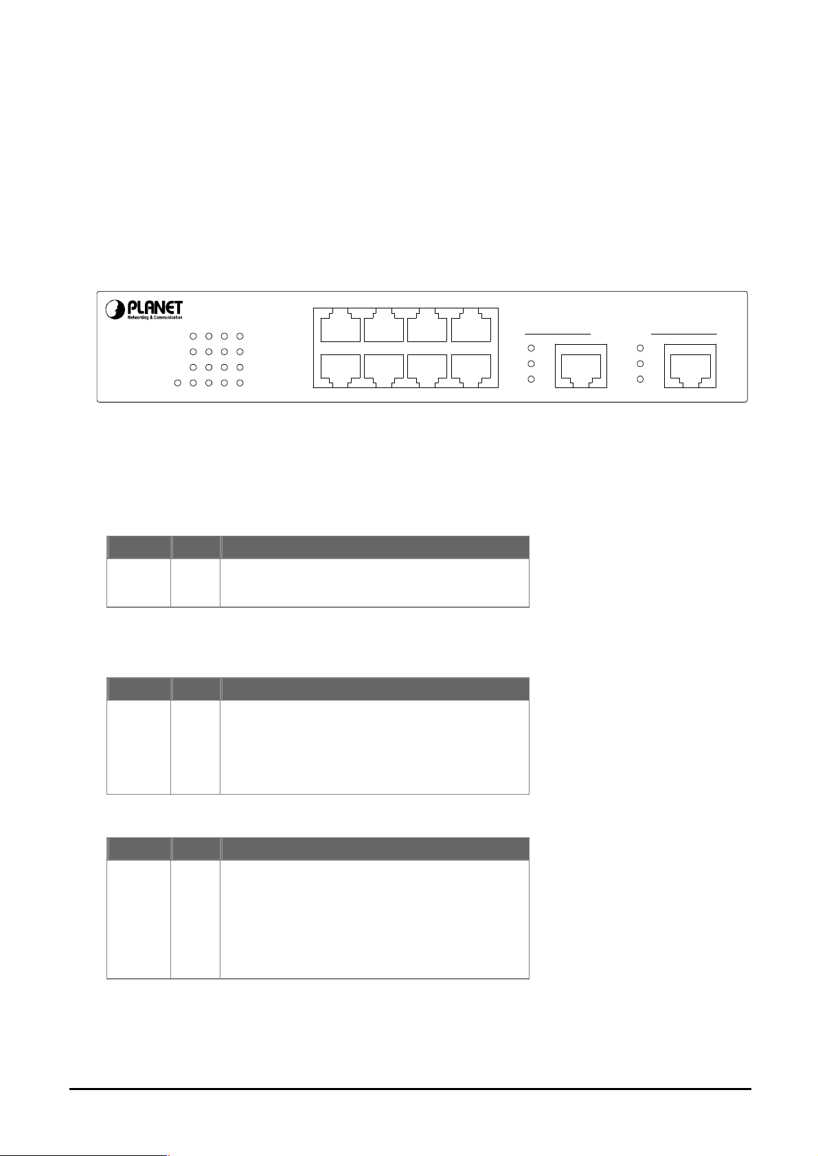
2.1 Front Panel
The unit front panel provides a simple interface monitoring the switching. It includes a power indicator for
each port.
WGSD-1020
2468
PWR
1357
LNK/ACT
100
LNK/ACT
100
Figure 1: WGSD-1020 Switch front panel
LED indicators:
System
LED Color Function
PWR Green
100Base-TX
LNK/ACT
LED Color Function
LNK / ACT Green
Lit on: Power on
Lit off: power off
established.
2468
1357
10/100/1000Mbps
Intelligent Ethernet Switch
LNK/
ACT
1000/
100
FDXFDX
1000 Base - T
9 10
LNK/
ACT
1000/
100
receiving data over that port.
100
LED Color Function
100 Orange
Each RJ45 station port on the Switch is assigned
one LED for monitoring port "Good Link" and data
traffic. The LED is normally OFF. After the power
show "Good Link" when port is been connected
with 100Mbps. LED will be off when port is run at
10Mbps.
- 3 -
Page 8

Lit: indicate the link through that port is successfully
itch is actively sending or
1000Base-T
LNK/ACT
LED Color Function
LNK / ACT Green
established.
Blink: indicate that the sw
receiving data over that port.
1000/100
LED Color Function
1000
100
Orange
Green
Lit: indicate that connection made through the
corresponding port is running at 1000Mbps.
Lit: indicate that connection made through the
corresponding port is running at 100Mbps.
FDX
LED Color Function
FDX Green Lit: indicate that the connection made through the
corresponding port is running in Full Duplex mode.
Blink: indicate that the connection is experiencing
collisions
2.2 Rear Panel
The rear panel of the Switch indicates an AC inlet power socket, which accepts input power from 100 to
240VAC, 50-60Hz.
100-240V AC
Console
9600, N, 8, 1
50/60 Hz
Figure 2: WGSD-1020 Switch rear panel
Power Notice:
1. The device is a power-required device, it means, it will not work till it is powered. If your networks
should active all the time, please consider using UPS (Uninterrupted Power Supply) for your device. It
will prevent you from network data loss or network downtime.
2. In some area, installing a surge suppression device may also help to protect your switch from being
damaged by unregulated surge or current to the Switch or the power adapter.
- 4 -
Page 9

2.3 Hardware Installation
2.3.1 Before start up
Before your installation, please refer to the followings for your cabling:
100Base-TX
All 100Base-TX ports come with auto-negotiation capability. They automatically support 100Base-TX
and 10Base-T networks. Users only need to plug a working network device into one of the 100Base-TX
ports, then turn on the Switch. The port will automatically runs in 10Mbps, 20Mbps, 100Mbps or
200Mbps after the negotiation with the connected device.
1000Base-T
The Switch are with two Gigabit port. This two ports support 10Mbps, 100Mbps and 1000Mbps speed
and also are full-duplex supported.
Cabling
Each 10/100/1000Base-T ports use RJ-45 sockets -- similar to phone jacks -- for connection of unshielded twisted-pair cable (UTP). The IEEE802.3ab Gigabit Ethernet standard requires 4-pair Category
5/5e UTP cable, IEEE 802.3u Fast Ethernet standard requires Category 5 UTP for 100Mbps
100Base-TX. 10Base-T networks can use Cat.3, 4, or 5 UTP (see table below). Maximum distance is
100meters (328 feet).
Port Type Cable Type Connector
10Base-T Cat 3, 4, 5, 2-pair RJ-45
100Base-TX Cat.5 UTP, 2-pair RJ-45
1000Base-T Cat. 5/5e UTP, 4-pair RJ-45
Any Ethernet devices like hubs/ PCs can connect to the Switch by using straight-through wires. The eight
10/100Mbps port and two 1000Base-T are auto-MDI/ MDI-X can be used on straight-through or
crossover cable.
2.3.2 Connecting end node or hub or switch
1. Place the Switch on a smooth surface or fasten the mounting brackets purchased separately with
the provided screws in a standard 10”/19” rack.
2. Connect the power cord to the power inlet socket of Switch and the other end into the local power
source outlet.
3. Connect other switch or PC to one port of the WGSD-1020 using Category 3/4/5 UTP/STP cabling.
4. Connect another switch or PC to the other port of Switch by following the same process as described
in Step3.
- 5 -
Page 10
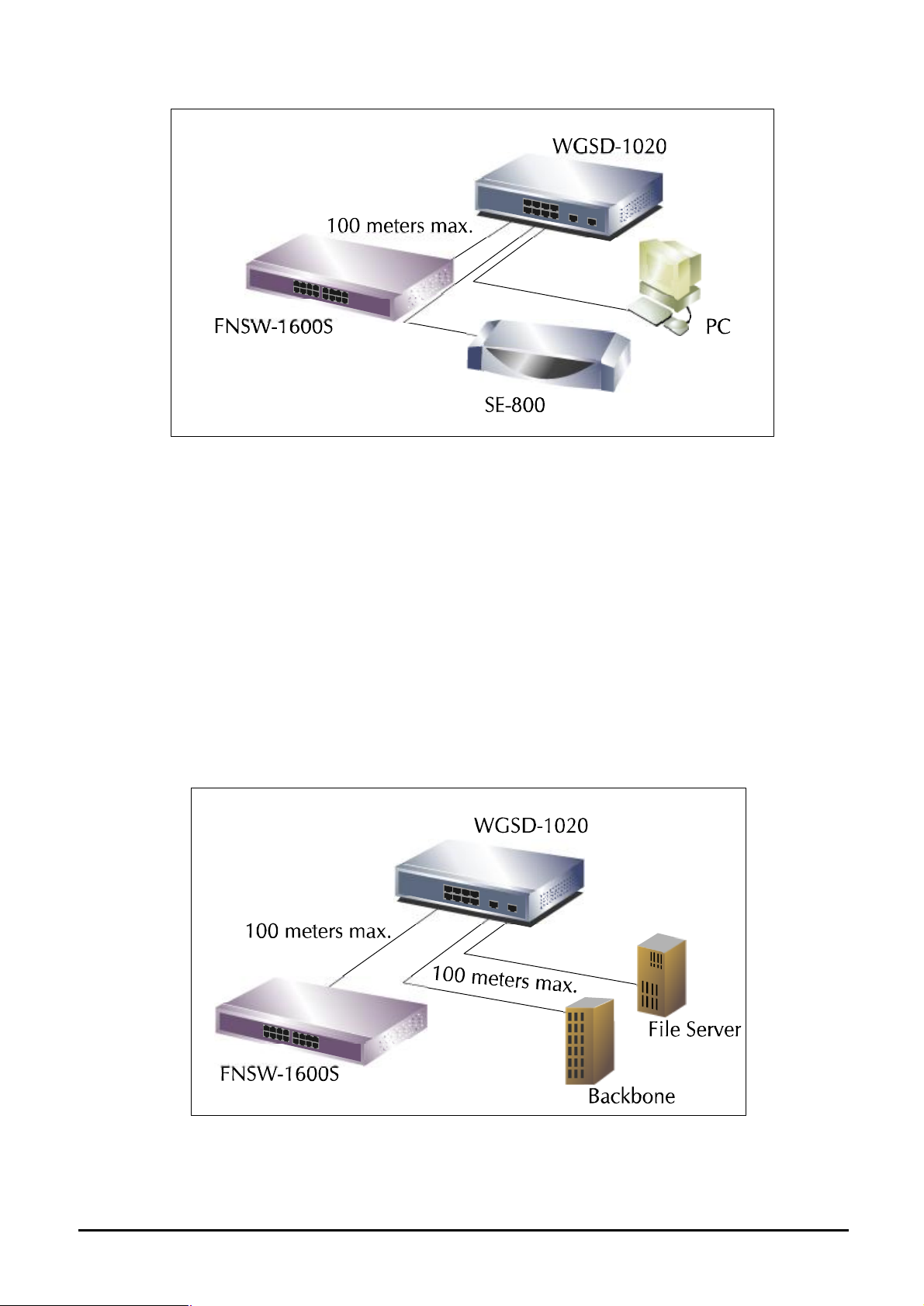
Figure 3. End node or Hub or Switch connection
Notice:
Cable distance for Switch
The cable distance between Ethernet Switch and hub/PC should not exceed 100 meter for
UTP/STP cable.
Make sure the wiring is correct
It can be used Category 3/4/5 cable in 10 Mbps operation. To reliably operate your network at
100Mbps and 1000Mbps, you must use an Unshielded Twisted-Pair (UTP) Category 5 cable, or
better Data Grade cabling. While a Category 3 or 4 cable may initially seem to work, it will soon
cause data loss.
2.3.3 Connecting to Network Backbone or Server
Connect to the Gigabit Ethernet ports with Category 5 copper cable for uplinking to a network
backbone or network server. These ports operate at 1000Mbps in full-duplex mode. A valid connection is indicated when the Link LED is light.
Figure 4: Network Backbone or Server connection
- 6 -
Page 11

3. SWITCH MANAGEMENT
This chapter describes how to manage the Switch. Topics include:
- Overview
- Management methods
- Assigning an IP address to the Switch
- Logging on to the Switch
3.1 Overview
The Switch provides a user-friendly, menu driven console interface. Using this interface, you can perform various switch configuration and management activities, including:
- Assigning an IP address
- Configuring Switch settings
- Display console port information
- Configuring each port status
- Configuring Port Trunking
- Setting up packet filters
- Setting up VLAN policy
- Configuring STP and port sniffer
- Configuring SNMP parameters
- TFTP Upgrading software
- Backup Switch configuration
Please refer to the following or Chapter 4 and 5 for the details.
3.2 Management Methods
There are three ways to manage the Switch:
- Local Console Management via the Switch serial port.
- Remote Console Management via a network or dial-up connection.
- Web Management via a network or dial-up connection.
- Using an SNMP Network Management Station.
3.2.1 Local Console Management
You can manage the Switch locally by connecting a VT100 terminal, or a personal computer or
workstation with terminal emulation software, to the Switch serial port. The terminal or workstation
connects to the Switch serial port using a null modem cable that has the appropriate connectors on
each end.
This management method is ideal when:
- The network is unreliable
- The Network Manager does not have direct network connection
- A Network Manager does not support SNMP
The serial port of the Switch default setting is set to 9600 baud using a character format of 8 data bits,
no parity, and 1 stop bit.
Therefore, configure the terminal or workstation to use these settings before you log on to the Switch.
You can change this default setting, if desired, after you log on.
- 7 -
Page 12

3.2.2 Remote Console Management
You can manage the Switch remotely by having a remote host establish a Telnet connection to the
Switch via an Ethernet or modem link.
Using this management method:
The Switch must have an Internet Protocol (IP) address
The Remote Console Management interface is identical in appearance and functionality to the Local
Console Management interface described in the previous section.
3.2.3 Web Management
You can manage the Switch remotely by having a remote host with web browser, such as Microsoft
Internet Explorer or Netscape Navigator.
Using this management method:
The Switch must have an Internet Protocol (IP) address accessible for the remote host
3.2.4 SNMP Management
You can manage the Switch across a LAN using an SNMP Network Management Station with a
graphical user interface.
This management method lets you monitor statistical counters and set switch parameters from the
remote Network Management Station.
Using this management method:
- The network must run the IP protocol.
- The Switch must have an IP address
3.3 Assigning an IP Address to the Switch
To manage the Switch remotely through the console port or with an SNMP Management Station, you
must assign an IP address to the Switch.
You assign IP address through the IP Settings screen. This procedure is described in Chapter 4, Section
IP Networking. It is strongly recommends you assign an IP address to the default VLAN (VLAN ID = 1) for
Remote Console Management and SNMP Network Management.
3.4 Logging on to the Switch
When you log on to the Switch console port for the first time, a sign-on string appears and you are
prompted for a console login name and password.
Welcome to PLANET WGSD-1020
Intelligent 8 + 2G Manageable Switch
Username: admin
Password:
Copyright 2002 (c) PLANET Technology Corp.
The factory default login name is admin without password. If you desire, you can add password after you
log on.
- 8 -
Page 13
4. CONSOLE INTERFACE
4.1 CONNECT TO PC
RS-232 serial cable
Use the bundled RS-232 serial cable and attach the 9-pin female connector to the male connector on the
switch. Plug the other side of this cable to your PC.
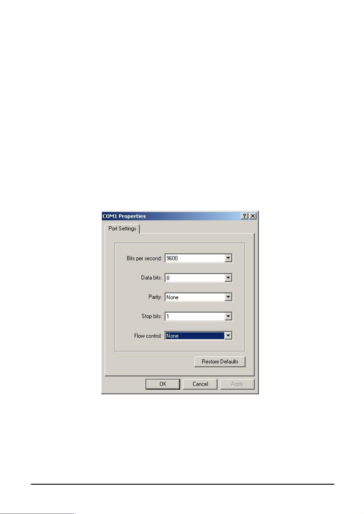
Hyper Terminal
In Windows 95/98/2000/XP, launch “HyperTerminal”, create a new connection, and adjust settings as
below:
§ Emulation: VT-100 compatible
§ Baud per second: 9600
§ Data bits: 8
§ Parity: None
§ Stop bits: 1
§ Flow Control: None
To gain a demo, please see the Figure 4-1.
Figure 4-1 Port Settings for console interface
- 9 -
Page 14
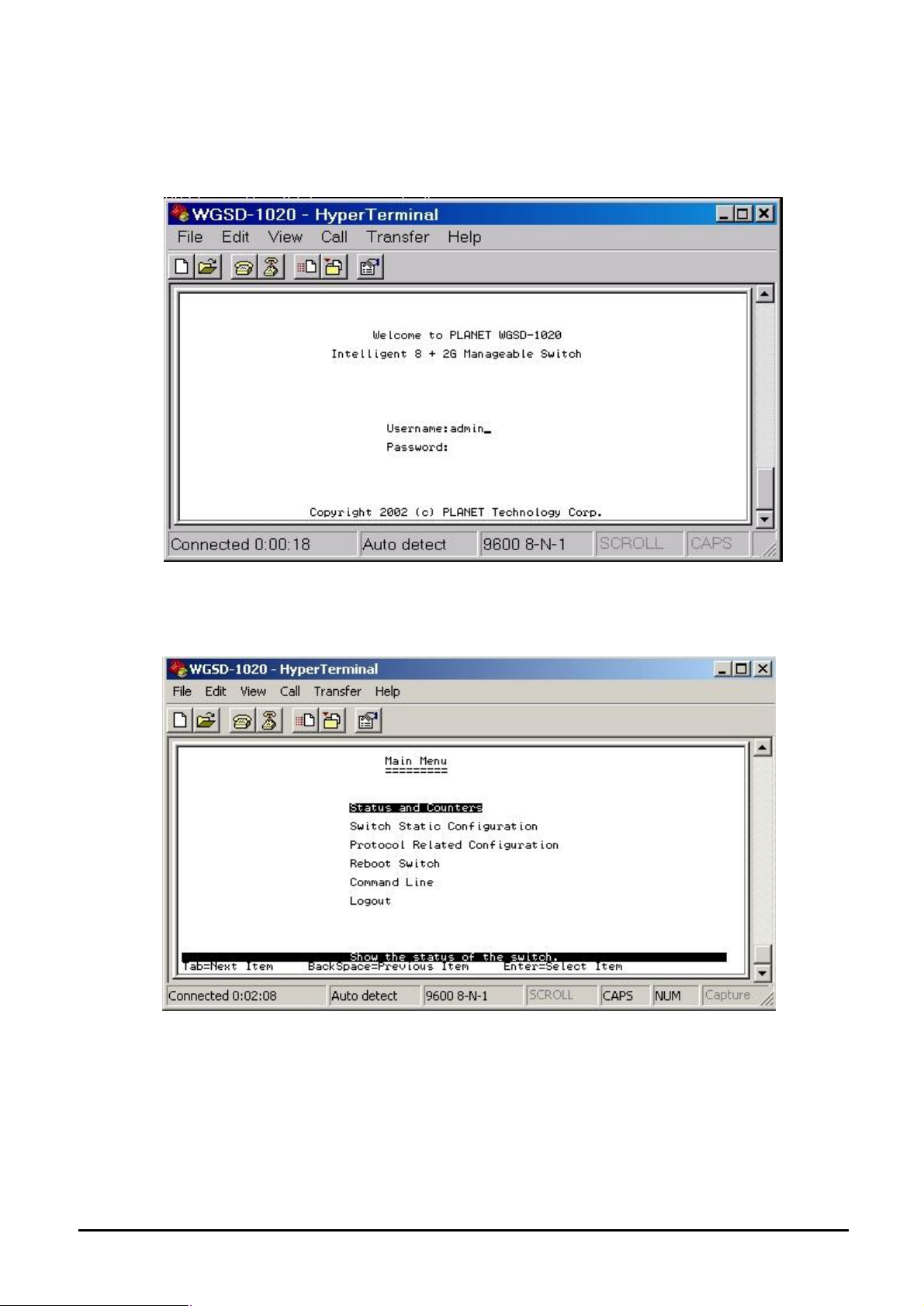
4.2 Login in
Login is required to access the command console after the self-test completes successfully. The factory
default user name is "admin" without password. You may change it in the System Menu. To access to
the Main Menu, please always enter the correct user name. (See Figure 4-2)
Figure 4-2 WGSD-1020 login screen
4.3 Main screen
After login the WGSD-1020, the main screen shows as below.
Figure 4-3 WGSD-1020 Main Menu screen
- 10 -
Page 15
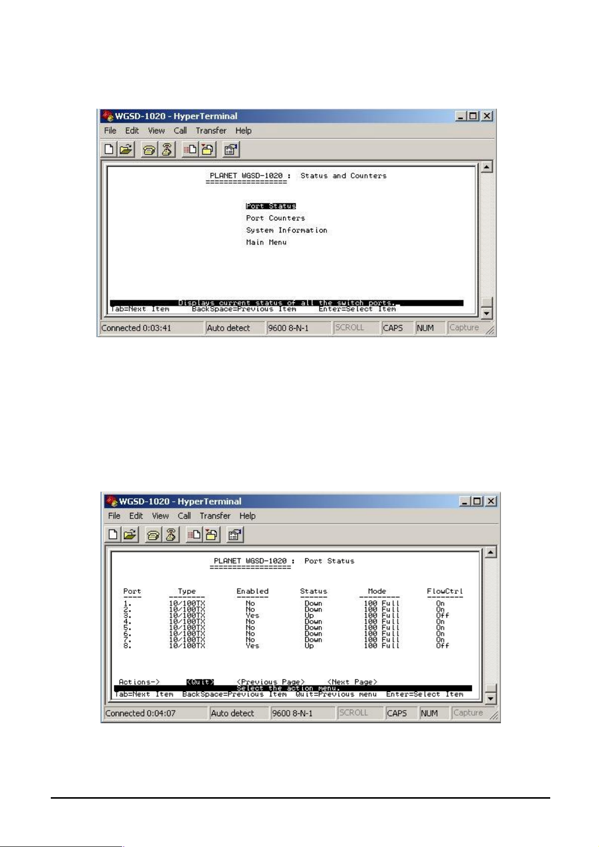
4.3.1 Status and Counters
From the Switch main menu screen (see Figure 4-3), highlight Status and counters and press enter.
The Status and Counters sub-screen in Figure 4-4 appears.
Figure 4-4 Status and Counters sub-screen
This sub-menu contains four items:
Port Status: Please refer to chapter 4.3.1.1.
Port Counters: Please refer to chapter 4.3.1.2
System Information: Please refer to chapter 4.3.1.3
Main Menu: return to main menu.
4.3.1.1 Port Status
Display the status of each port on WGSD-1020.
Figure 4-5 Port Status screen
- 11 -
Page 16
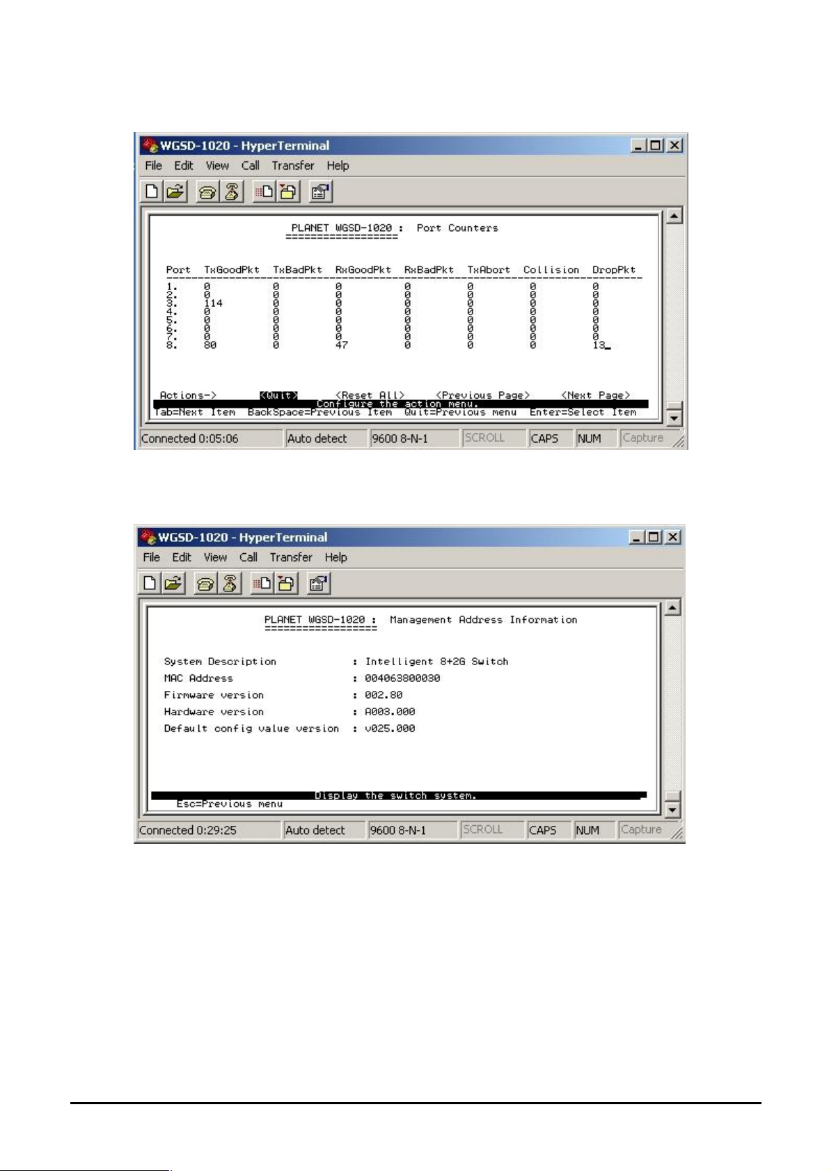
4.3.1.2 Port Counters
Display the traffic counters of each port on WGSD-1020.
Figure 4-6 Port Counters screen
4.3.1.3 System Information
Display the Switch information.
Figure 4-7 System Information screen
- 12 -
Page 17
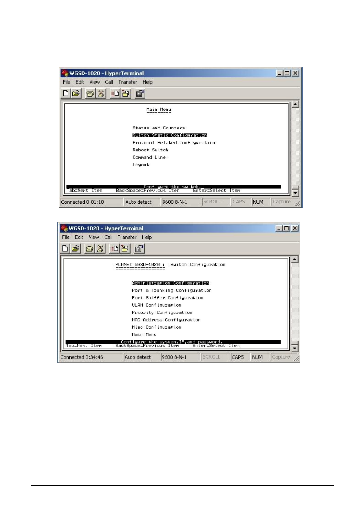
4.3.2 Switch Static Configuration
From the Switch Static Configuration screen (see Figure 4-8), highlight Switch Static Configuration and
press Enter. The Switch Static Configuration sub-screen in Figure 4-9 appears.
Figure 4-8 Switch Static Configuration screen
Figure 4-9 Switch Static Configuration sub-screen
This sub-menu contains eight items:
Administration Configuration: please refer to chapter 4.3.2.1.
Port & Trunking Configuration: please refer to chapter 4.3.2.2.
Port Sniffer Configuration: please refer to chapter 4.3.2.3.
VLAN Configuration: please refer to chapter 4.3.2.4.
Priority Configuration: please refer to chapter 4.3.2.5
MAC Address Configuration: please refer to chapter 4.3.2.6.
Misc Configuration: please refer to chapter 4.3.2.7
Main Menu: please refer to chapter 4.3.2.8.
- 13 -
Page 18
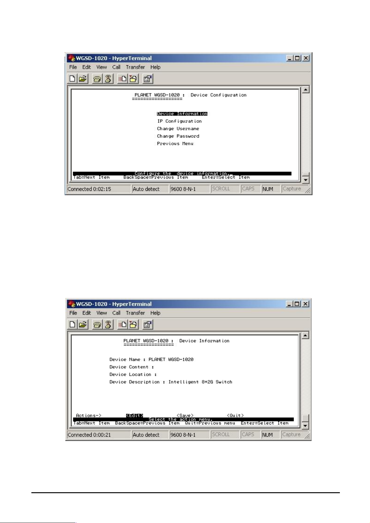
4.3.2.1 Administration Configuration
Figure 4-10 Device Configuration screen
This sub-menu contains five items:
Device Information: please refer to chapter 4.3.2.1.1
IP Configuration: please refer to chapter 4.3.2.1.2
Change Username: please refer to chapter 4.3.2.1.3
Change Password: please refer to chapter 4.3.2.1.4
Previous Menu: return to previous menu
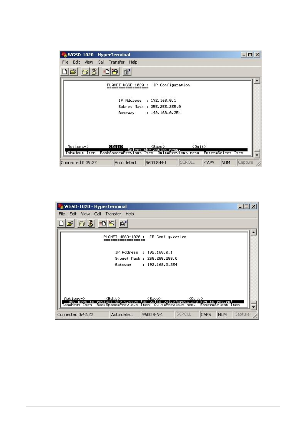
4.3.2.1.1 Device Information
Display the Device information.
Figure 4-11 Device Information screen
- 14 -
Page 19
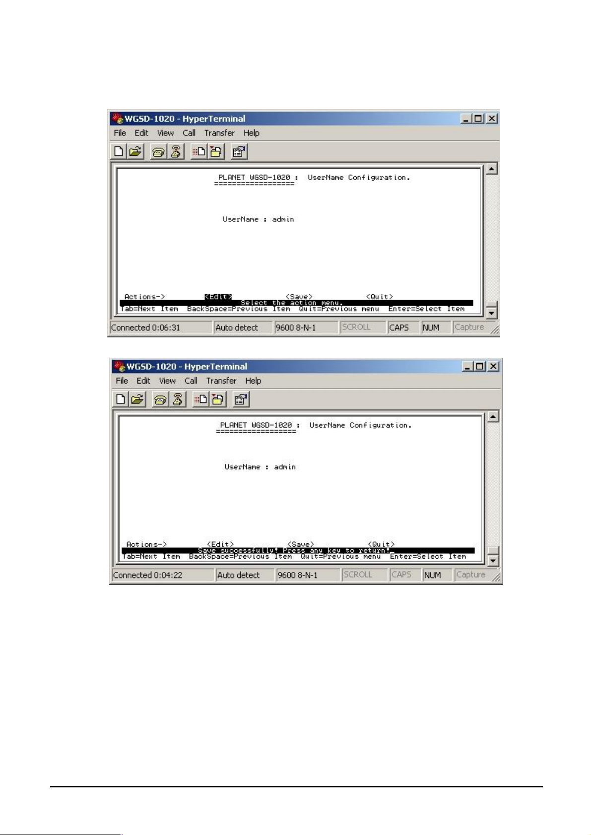
4.3.2.1.2 IP Configuration
Press ”Edit” to modify the IP address, Subnet Mask and Gateway.
Figure 4-12 IP Configuration screen
Press “Tab” to move the cursor to IP Address, Subnet Mask and Gateway to input new value.
After setup completed, press “ctrl-A” to save the current configuration. The following screen in
Figure 4-13 appears.
Figure 4-13 IP Configuration save successful screen
You need to reboot the Switch to take effect of your IP configuration.
- 15 -
Page 20
4.3.2.1.3 Change Username
Press “Edit” to input the new username and choose “save” to save the current configuration.
The following screen in Figure 4-14 appears.
Figure 4-14 Edit Username Configuration screen
Figure 4-15 Username Configuration save successfully screen
- 16 -
Page 21
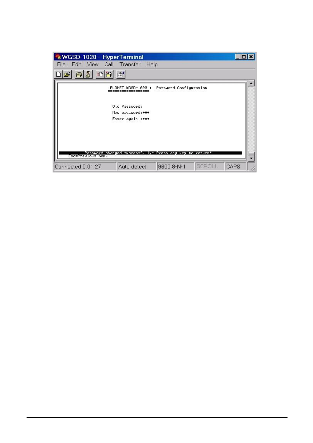
4.3.2.1.4 Change Password Allow user to modify the password.
Figure 4-16 Password Configuration screen
Modify the password procedure:
1. Enter old password: empty (Default is no password)
2. Enter new password: * * * ( New password 123)
3. Enter again : * * * ( New password 123)
4. Press “Enter” to apply the new password.( see the Figure 4-16)
- 17 -
Page 22
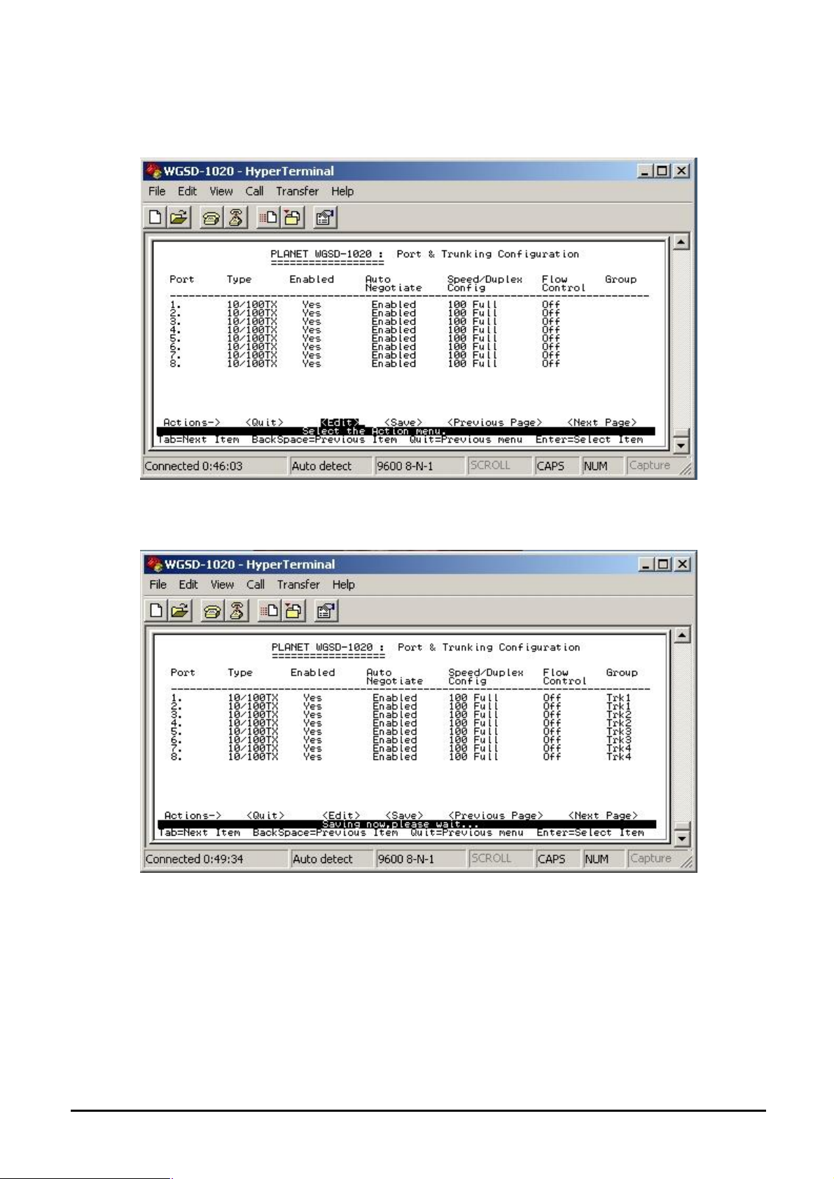
4.3.2.2 Port & Trunking Configuration
From the Switch Static Configuration sub-screen (see Figure 4-9), highlight Port Trunk Configuration
and press enter. The Port Trunk Configuration screen in Figure 4-17 appears.
Figure 4-17 Port & Trunking Configuration screen
Press ” Edit” to configure the trunk group. After setup completed, press “ctrl-A” to save the current
configuration. The following screen in Figure 4-18 and 4-19 appears.
Figure 4-18 Save Port & Trunking Configuration process screen
- 18 -
Page 23
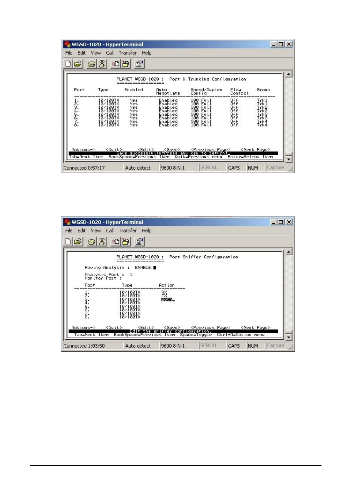
Figure 4-19 Port & Trunking Configuration save successfully screen
4.3.2.3 Port Sniffer Configuration From the Switch Static Configuration sub-screen (see Figure 4-9), highlight Port Sniffer
Configuration and press enter. The Port Sniffer Configuration screen in Figure 4-20 appears.
Figure 4-20 Port Sniffer Configuration screen
Press ”Edit” to configure the Port Sniffer function.
Roving Analysis: provide disable or enable port sniffer function.
Analysis Port: allow seeing all monitor port traffic; you can connect sniffer port to LAN Explorer,
Session Wall, Sniffer Pro or Netxray.
Monitor port: choose one specific port for monitor the traffic of RX and TX or both (RX and TX) of
Analysis port
After setup completed, press “ctrl-A” and choose “save” to save the current configuration.
- 19 -
Page 24
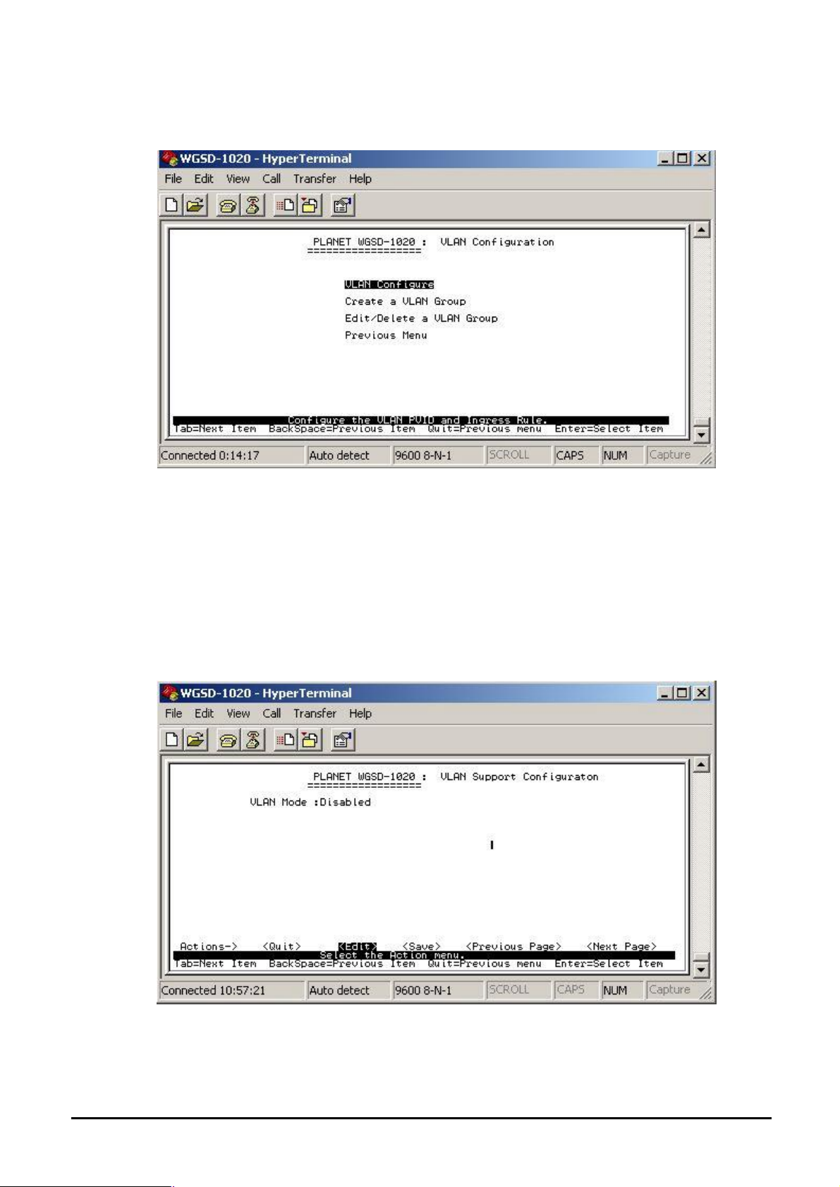
4.3.2.4 VLAN Configuration
From the Switch Static Configuration sub-screen (see Figure 4-9), highlight VLAN Configuration
and press enter. The VLAN Configuration screen in Figure 4-21 appears.
This sub-menu contains four items:
Figure 4-21 VLAN Configuration screen
VLAN Configure: please refer to chapter 4.3.2.4.1
Create a VLAN Group: please refer to chapter 4.3.2.4.2
Edit/ Delete a VLAN Group: please refer to chapter 4.3.2.4.3
Previous Menu: return to previous menu
4.3.2.4.1 VLAN Configure
Provide disable /enable VLAN function and 3 VLAN mode selections.
Figure 4-22 VLAN Configuration screen
Press “Ctrl-A” to choose “Edit” for enable VLAN function and select the 3 VLAN modes through
the space bar. The IEEE 802.1Q VLAN screen in Figure 4-23 appears. The maximum PVID is
4094.
- 20 -
Page 25
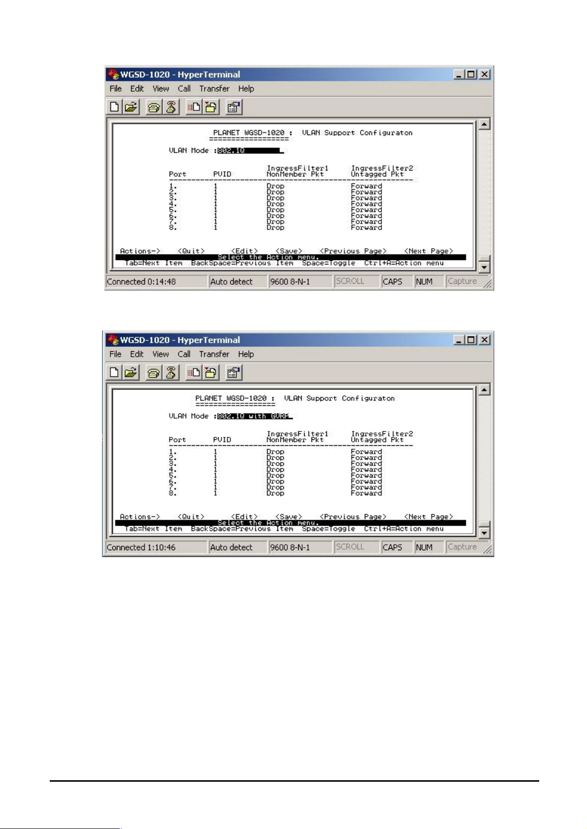
.
Figure 4-23 IEEE 802.1Q VLAN Configuration screen
Press space bar switch to 802.1Q with GVRP in VLAN mode. The screen in Figure4-24 appears.
Figure 4-24 IEEE 802.1Q VLAN with GVRP screen
Press space bar switch to Port-based VLAN in VLAN mode. The screen in Figure4-25 appears.
- 21 -
Page 26
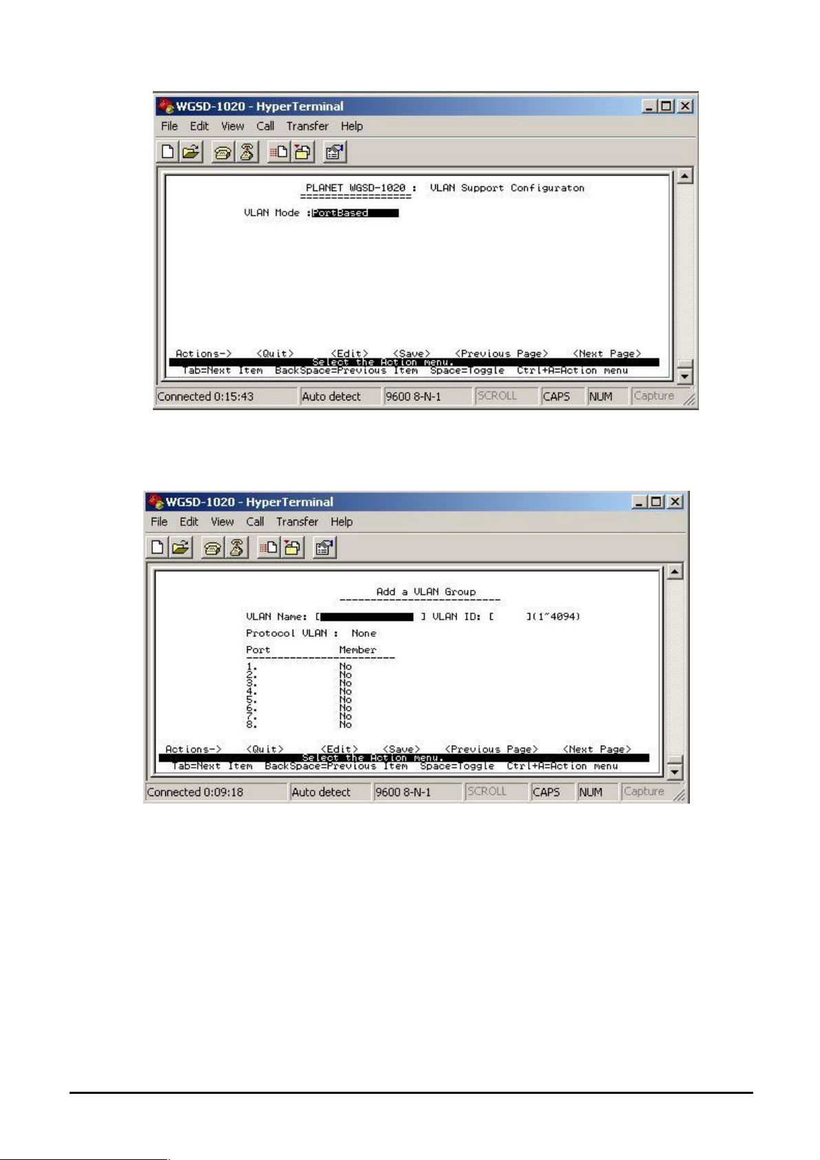
Figure 4-25 Port-based VLAN screen
4.3.2.4.2 Create a VLAN Group
To add a VLAN group, the VLAN ID range is 1-4094.
Figure 4-26 Add a VLAN Group screen
Add a VLAN Group procedure:
1. Press “ Edit” to input the VLAN name and VLAN ID.
2. Choose different VLAN protocol through the space bar.
3. Under 802.1Q and 802.1Q VLAN mode. Set Tagged, Untagged or no (not belong to any
VLAN group) of each port.
4. Under Port-based VLAN mode. Set Member or no (not belong to any VLAN group) of each port.
5. Press “Ctrl-A” and choose “Save” to save the current configuration.
- 22 -
Page 27
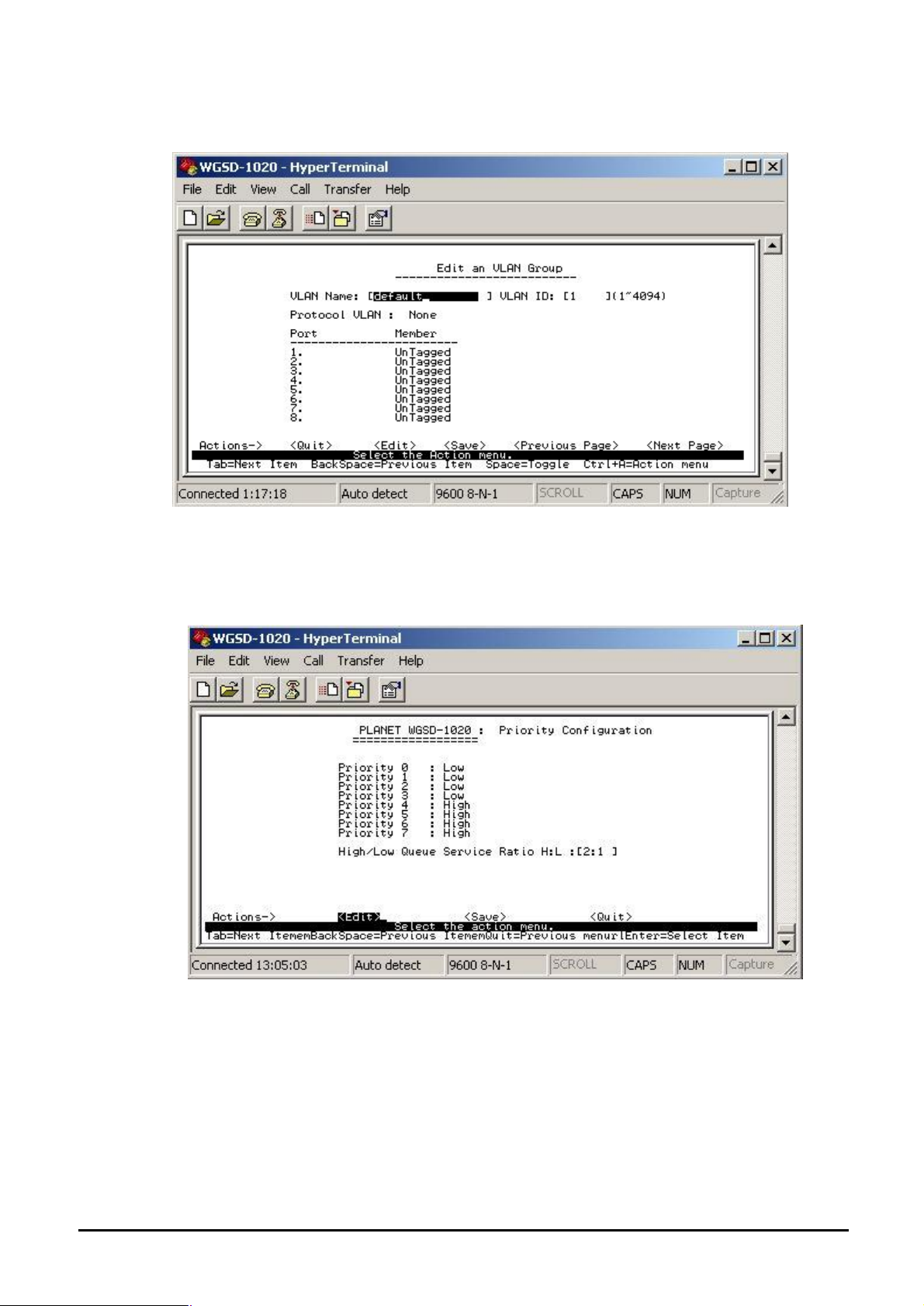
4.3.2.4.3 Edit / Delete VLAN Group
Allow editing and deleting VLAN GROUP.
Figure 4-27 Edit a VLAN Group screen
4.3.2.5 Priority Configuration
Displays the options available for assigning High and Low priority to each port.
From the Switch Static Configuration sub-screen (see Figure 4-9), highlight Priority
Configuration and press enter. The Priority Configuration screen in Figure 4-28 appears
Figure 4-28 Priority Configuration screen
Press ” Edit” to assigning High or Low priority of each port.After setup completed, press
“Ctrl-A” and choose “Save” to save the current configuration. The screen in Figure 4-29
appears.
- 23 -
Page 28
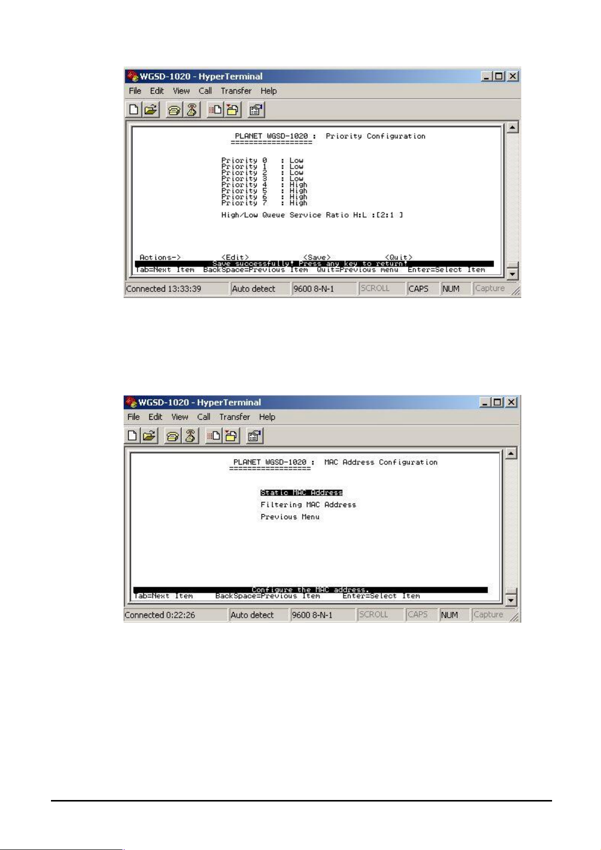
Figure 4-29 Priority Configuration save successfully screen
Press any key return to the previous menu.
4.3.2.6 MAC Address Configuration
Provide static MAC address and Filtering MAC address and previous Menu. From the Switch
Static Configuration sub-screen (see Figure 4-9), highlight MAC address Configuration and
press enter. The MAC address Configuration screen in Figure 4-30 appears.
Figure 4-30 MAC Address Configuration screen
This sub-menu contains 3 items.
Static MAC Address: please refer to chapter 4.3.2.6.1.
Filtering MAC Address: please refer to chapter 4.3.2.6.2.
Previous Menu: return to previous menu.
- 24 -
Page 29

4.3.2.6.1 Static MAC Address
Figure 4-31 Static MAC Address Configuration screen
Press, “Add” to add a static MAC address, after setup completed, press “Ctrl-A” and choose
“Save” to save the current configuration. The screen in Figure 4-32 appears
Figure 4-32 Static MAC Address Configuration screen
Press any key return to the previous menu.
- 25 -
Page 30

4.3.2.6.2 Filtering MAC Address
Figure 4-33 Filter MAC Address Configuration screen
Press “Add” to add a Filter MAC address, after setup completed, press “Ctrl-A” and choose
“Save” to save the current configuration. The screen in Figure 4-34 appears
Figure 4-34 Filter MAC Address Configuration save successfully screen
- 26 -
Page 31

4.3.2.7 Misc Configuration
From the Switch Static Configuration sub-screen (see Figure 4-9), highlight Misc Configuration
and press enter. The Misc Configuration sub-screen in Figure 4-35 appears.
Figure 4-35 Misc Configuration screen
This sub-menu contains five items:
Port Security: please refer to chapter 3.3.2.7.1
MAC Age Interval: please refer to chapter 3.3.2.7.2
Broadcast Storm Filtering: please refer to chapter 3.3.2.7.3
Max bridge transmits delay bound: please refer to chapter 3.3.2.7.4
Previous Menu: return to previous menu
4.3.2.7.1 Port Security
Provide disable or enable security of each port. The screen in Figure 3-36 appears.
Figure 4-36 Port Security Configuration screen
- 27 -
Page 32

4.3.2.7.2 MAC Age Interval Allow to setting the aging time of WGSD-1020. The maximum value is 765 sec.
Figure 4-37 Aging Time Configuration screen
Press “Edit” to input the aging time value and press enter to choose the “save” for save the current
configuration. The screen in Figure 4-38 appears.
Figure 4-38 Aging time Configuration save successfully screen
Press any key for return to the previous menu.
- 28 -
Page 33

4.3.2.7.3 Broadcast Storm Filtering Provide disable and 5, 10, 15, 20 or 25 Broadcast storm filter mode.
Figure 4-39 Broadcast storm filter screen
Broadcast Storm Filter setup procedure:
1. Press “Edit” to input 5, 10, 15, 20 or 25 broadcast storm filter.
2. After setup completed, press” Ctrl-A” to “Action menu” and choose “save” to save the current
configure. The screen in Figure 4-40 appears.
3. Press any key for return to the previous menu.
4.3.2.7.4 Max Bridge Transmit Delay Bound
Figure 4-40 Max Bridge transmit delay bound screen
This sub-menu contains three items:
Max bridge transmit delay bound: off (default mode)
Enable Delay Bound: Disabled ( default mode)
Max Delay Time: 0 (default mode)
- 29 -
Page 34

4.3.2.7.4.1 Max bridge transmit delay bound Provide “OFF” and 1, 2, or 4 sec. for selection.
Figure 4-41 Max Bridge transmit delay bound screen
Setup procedure:
1. Press “Edit” to input OFF and 1, 2 or 4 sec.
2. After setup completed, press” Ctrl-A” to “Action menu” and choose “save” to save the current
configure. The screen in Figure 4-42 appears.
Figure 4-42 Max Bridge transmit delay bound save successfully screen
3. Press any key for return to the previous menu.
- 30 -
Page 35

4.3.2.7.4.2 Enable Delay Bound Provide disable or enable Delay Bound function.
Figure 4-43 Enable Delay Bound screen
Setup procedure:
1. Choose disable or enable through the space bar.
2. After setup completed, press” Ctrl-A” to “Action menu” and choose “save” to save the current
configure. The screen in Figure 4-44 appears.
Figure 4-44 Enable Delay Bound save successfully screen
3. Press any key for return to the previous menu.
- 31 -
Page 36

4.3.2.7.4.3 Max Delay Time
Allow inputting the Max Delay Time.
Figure 4-45 Max Delay Time screen
Setup procedure:
1. Press “ Edit” to input the Max Delay Time value.
2. After setup completed, press” Ctrl-A” to “Action menu” and choose “save” to save the current
configure. The screen in Figure 4-46 appears.
Figure 4-46 Max Delay Time save successfully screen
3. Press any key for return to the previous menu.
4.3.2.8 Main Menu
Return to the main menu.
- 32 -
Page 37

4.3.3 Protocol Related Configuration
From the Switch main menu screen (see Figure 4-3), highlight Protocol Related Configuration and
press enter. The Status and Counters screen in Figure 4-47 appears.
Figure 4-47 The Protocol Related Configuration screen
This subnet menu contains five items:
STP: please refer to chapter 4.3.3.1.
SNMP: please refer to chapter 4.3.3.2.
GVRP: provide disable or enable GVRP function.
LACP: provide LACP configuration.
Previous Menu: return to Main menu.
4.3.3.1 STP
Provide Spanning Tree configuration.
Figure 4-48 Spanning Tree Protocol screen
- 33 -
Page 38

This sub-menu contains four items:
STP Enable: please refer to chapter 4.3.3.1.1
System Configuration: please refer to chapter 4.3.3.1.2
Per port Configuration: please refer to chapter 4.3.3.1.3
Previous Menu: return to previous menu.
4.3.3.1.1 STP Enable
Provide disable or enable STP function
Figure 4-49 STP enable /disable screen
Setup procedure:
1. Press “ Edit” to disable or enable STP function.
2. After setup completed, press” Ctrl-A” to “Action menu” and choose “save” to save the current
configure. The screen in Figure 4-50 appears.
Figure 4-50 STP enable save successfully screen
3. Press any key for return to the previous menu.
- 34 -
Page 39

4.3.3.1.2 System Configuration Allow modify the STP system configuration.
Figure 4-51 STP system configuration screen
Setup procedure:
1. Press “ Edit” to modify the Spanning Tree Parameters.
2. After modify completed, press” Ctrl-A” to “Action menu” and choose “save” to save the current configure. The screen in Figure 4-52 appears.
Figure 4-52 STP system configuration save successfully screen
3. Press any key for return to the previous menu.
- 35 -
Page 40

4.3.3.1.3 Per Port Configuration
Allow edit per port STP configuration.
Figure 4-53 STP Port configuration screen
Setup procedure:
1. Press “ Edit” to modify the path cost and priority of each port.
2. After setup completed, press” Ctrl-A” to “Action menu” and choose “save” to save the current
configure. The screen in Figure 4-54 appears.
Figure 4-54 STP Port configuration screen
3. Press any key for return to the previous menu.
- 36 -
Page 41

4.3.3.2 SNMP
Provide SNMP configuration.
Figure 4-55 SNMP configuration screen
This subnet menu contains four items:
1. System Options: please refer to chapter 4.3.3.2.1
2. Community Strings: please refer to chapter 4.3.3.2.2
3. Trap Managers: please refer to chapter 4.3.3.2.3
4. Previous Menu: please refer to chapter 4.3.3.2.4
4.3.3.2.1 System Options
Allow inputting the system name, system location, system contact.
Figure 4-56 System Options configuration screen
- 37 -
Page 42

Setup procedure:
1. Press “ Edit” to input the system name, system contact, system location.
2. After setup completed, press” Ctrl-A” to “Action menu” and choose “save” to save the current
configure. The screen in Figure 4-57 appears.
Figure 4-57 System Options configuration save successfully screen
3. Press any key for return to the previous menu.
4.3.3.2.2 Community Strings
Allow adding SNMP community name.
Figure 4-58 SNMP Community configuration screen
Setup procedure:
1. Press “Add” to enter into “add SNMP community” screen, then press “Edit” a new community
name and adjust the write access mode..
2. After setup completed, press” Ctrl-A” to “Action menu” and choose “save” to save the current
configure. The screen in Figure 4-59 appears.
- 38 -
Page 43

Figure 4-59 Add SNMP Community name save successfully screen
3. Press any key for return to the previous menu.
4.3.3.2.3 Trap Managers
Allow adding Trap Managers.
Figure 4-60 Add SNMP Community name screen
Setup procedure:
1. Press “Add” to enter into “Trap Managers” screen, then press “Edit” for input IP address and
Community name.
2. After setup completed, press” Ctrl-A” to “Action menu” and choose “save” to save the current
configure. The screen in Figure 4-61 appears.
- 39 -
Page 44

Figure 4-61 Add Trap managers screen
3. Press any key for return to the previous menu.
4.3.3.2.4 Previous Menu
Return to the previous menu.
4.3.3.3 GVRP
Provide disable or enable GVRP function
Figure 4-62 GVRP screen
Setup procedure:
1. Press “Edit” to disable or enable the GVRP function.
2. After setup completed, press” Ctrl-A” to “Action menu” and choose “save” to save the current
configure. The screen in Figure 4-63 appears.
- 40 -
Page 45

Figure 4-63 GVRP save successfully screen
3. Press any key for return to the previous menu.
4.3.3.4 LACP
This subnet menu contains four items:
1. Aggregator Settings: please refer to chapter 4.3.3.4.1.
Figure 4-64 LACP Configuration screen
2. State Activity: please refer to chapter 4.3.3.4.2
3. LACP Status: please refer to chapter 4.3.3.4.3
4. Previous Menu: please refer to chapter 4.3.3.4.4
- 41 -
Page 46

4.3.3.4.1 Aggregator Settings
Allow editing the LACP Group configuration.
Figure 4-65 Aggregator settings screen
4.3.3.4.2 State Activity Allow to set LACP port state activity of each port.
Figure 4-66 LACP port state Active configuration screen
Setup procedure:
1. Press “Edit” for “passive” or “Active” selection of each port.
2. After setup completed, press” Ctrl-A” to “Action menu” and choose “save” to save the current
configure. The screen in Figure 4-67 appears.
- 42 -
Page 47

Figure 4-67 LACP port state Active configuration screen
3. Press any key for return to the previous menu.
4.3.3.4.3 LACP Status
Display the LACP groups status.
Figure 4-68 LACP Group Status screen
4.3.3.4.4 Previous Menu Return to the previous menu.
4.3.3.5 Main Menu
Return to the main menu.
- 43 -
Page 48

4.3.4 Reboot Switch
Provide reboot the Switch and reset to switch to default mode.
Figure 4-69 Reboot Switch screen
This subnet menu contains three items:
1. Default: please refer to chapter 4.3.4.1.
2. Restart: please refer to chapter 4.3.4.2.
3. Previous Menu: refer to chapter 4.3.4.3
4.3.4.1 Default
Reset the Switch to the factory default mode. The screen in Figure 4-70 appears.
Figure 4-70 Reset Switch screen
Press “Y” for reboots the switch to default mode. The following screen appears in Figure 4-71.
- 44 -
Page 49

Figure 4-71 Resetting Switch screen
4.3.4.2 Restart
Provide restart the Switch. The screen in Figure 4-72 appears.
Figure 4-72 Restart Switch screen
4.3.4.3 Previous Menu
Return to the main menu.
- 45 -
Page 50

4.3.5 Command Line
Provide system command for WGSD-1020. The screen in Figure 4-73 appears.
Figure 4-73 Command line screen
Type “Help” command for helps parameters. The screen in Figure 4-74 appears.
4.3.6 Logout
Provide logout the Switch.
Figure 4-74 Help parameters screen
- 46 -
Page 51

5. WEB MANAGEMENT
Before login the Web interface of WGSD-1020, please setup the “IP Address” with local serial console
port( RS232 port) and use this IP address to configure WGSD-1020 through the Telnet and Web interface.
Or modify your PC’s IP domain to the same with WGSD-1020 then use the default IP address to remote
configure WGSD-1020 through the Telnet and Web interface.
5.1 Login in to the Switch
To access the Web-browser interface you must first enter the user name. The default user name is
"admin" without password. You will see the following screen comes out on the Web browser program:
Figure 5-1 The WGSD-1020 login screen
After the Username and Password is entered, you will see the main menu screen.
Figure 5-2 The main screen of WGSD-1020 Web Page
- 47 -
Page 52

5.2 Port Status
This section provides detail status of each port from WGSD-1020.
Figure 5-3 WGSD-1020 Port Status Web Page screen
State: display the link state of each port on WGSD-1020.
Link Status: the state of the link test, indicating a valid link partner device. "Up" means a device is suc-
cessful
connected to the port. “Down” means no device is connected.
Auto-Negotiation: auto-negotiation state of each port on WGSD-1020.
Speed Status: display the speed state of each port on WGSD-1020.
Duplex Status: display the speed duplex mode of each port on WGSD-1020.
Flow Control: display the flow control state of each port on WGSD-1020.
Config: display the current configuration of each port.
Actual: display the current state of each port on WGSD-1020.
- 48 -
Page 53

5-3 Port Statistics
For those selected port, this function could provide you with an individual statistical counter. It is a useful
page for administrator to monitor each port’s usage condition. Also, it is helpful to troubleshooting
network problems. Please note that the updating rate is defined in System Configuration menu.
Figure 5-4 WGSD-1020 Port Statistics Web Page screen
- 49 -
Page 54

5-4 Administrator
This section contains management function on WGSD-1020.
Figure 5-5 WGSD-1020 Administrator Web Page screen
This management function is shown as below:
IP Address: please refer to section 5.4.1
Switch Settings: please refer to section 5.4.2
Console Port Information: please refer to section 5.4.3
Port Controls: please refer to section 5.4.4
Trunking: please refer to section 5.4.5
Filter Database: please refer to section 5.4.6
VLAN Configuration: please refer to section 5.4.7
Spanning Tree: please refer to section 5.4.8
Port Sniffer: please refer to section 5.4.9
SNMP: please refer to section 5.4.10
Security Manager: please refer to section 5.4.11
- 50 -
Page 55

5.4.1 IP Address
This section allows modify the IP address, Subnet Mask, Gateway of WGSD-1020.
Figure 5-6 WGSD-1020 modify IP Address Web Page screen
After modifying the new IP address, Subnet Mask, Gateway, please click “Apply” button then the following
screen in Figure 5-7 appears. Click “Reboot” button. WGSD-1020 will reboot to take effect for the new IP
address, Subnet Mask, Gateway.
Figure 5-7 WGSD-1020 Reboot Switch System Web Page screen
- 51 -
Page 56

You can click” Help” button; the IP Address Overview screen in Figure 5-8 appears.
Figure 5-8 WGSD-1020 IP Address Overview Web Page screen
Click “Close” to close this screen.
- 52 -
Page 57

5.4.2 Switch Settings
This section provide Switch basic information and allow modify the Switch settings
Figure 5-9 WGSD-1020 Switch Basic Settings Web Page screen
5.4.2.1 Basic: Description: display the Switch system name. MAC address: display the Switch MAC Address.
Firmware version: display the Switch current firmware version.
Hardware version: display the Switch current hardware version.
Default config value version: display the default eeprom version.
- 53 -
Page 58

Figure 5-10 WGSD-1020 Switch Advanced Settings Web Page screen
5.4.2.2 Advanced: Enter the settings, then click Submit to apply the changes on this page.
MAC Table Address Entry Age-Out Time: type the number of seconds that an inactive MAC ad-
dress remains in the Switch’s address table. The valid range is 300-765 seconds. The default value
is 300 sec.
Max bridge transmit delay bound control: limit the packets queuing time in switch, if enable this
function, the packets queued exceed will be drop. The valid value is 1 sec., 2 sec. and 4 sec. and off.
Default value is 2 sec.
Broadcast Strom Filter mode: provide 5%, 10%, 15%, 20%, 25% and off for broadcast storm
control activity.
Priority Queue Service:
First Come First Served: the sequence of packets sent is depend on arrive order.
All High before Low: the high priority packets sent before the low priority packets.
WRR (Weighted Round Robin): select the preference given to packets in the Switch’s high-priority
queue. These options represent the number of high priority packets sent before one low priority
packet. For example: High weight: 5 and Low weight 2. It means WGSD-1020 sends 5 high priority
packets before sending 2 low priority packets.
Enable Delay Bound: limit the low priority packets queuing time in WGSD-1020. Default maximum
delay time is 255 ms. If the low priority packet stays in Switch exceed Max delay time, it will be sent.
The valid range is 1-255 ms.
QoS Policy: High Priority Levels: provide 0-7 priority levels can map to high or low queue.
Protocol Enable Setting
Enable STP Protocol: provide disable or enable STP protocol. Default mode is enabling.
Enable IGMP Protocol: provide disable or enable IGMP protocol. Default mode is enable.
VLAN Operation Mode: IEEE 802.1Q(Port-based) with GVRP VLAN mode.
IEEE 802.Q( Port-based) without GVRP VLAN mode.
- 54 -
Page 59

Port-based VLAN mode
Note: Make sure of “Max bridge transit delay bound control” is enabled before enabling
delay bound, because enable delay bound must work under “ Max bridge transit delay
bound control” is enabled.
You can click “Help” button; the following screen in Figure 5-11 appears.
Figure 5-11 WGSD-1020 Configuring the Switch Web Page screen
Click “Close” to close this screen.
- 55 -
Page 60

5.4.3 Console Port Information
Display the WGSD-1020 console port information.
Figure 5-12 WGSD-1020 Console Information Web Page screen
You can click “Help” button; the following screen in Figure 5-13 appears.
Figure 5-13 WGSD-1020 Console Setting Help Web Page screen
Click “Close” to close this screen.
- 56 -
Page 61

5.4.4 Port Controls
This section introduces detail settings of per port on WGSD-1020.
Figure 5-14 WGSD-1020 Port Controls Web Page screen
State: provide disable or enable any port of WGSD-1020.
Auto-Negotiation: allow disable or enable Auto-negotiation of any port on WGSD-1020.
Speed: allow set various speed mode of any port on WGSD-1020.
Duplex: allow to set half or full duplex mode of any port on WGSD-1020.
Flow Control: provide disable or enable flow control function.
- 57 -
Page 62

5.4.5 Trunking
This section displays the screen for trunking a group of ports together to speed up data transmission.
Figure 5-15 WGSD-1020 Trunking Web Page screen
5.4.5.1 Aggregator Setting parameters: System Priority: A value used to identify the active LACP. The Switch with lowest value has the
highest priority and is selected as the active LACP.
Group ID: After creating a new link aggregation across two or more ports, choose the “Group ID”
and click “Get”.
LACP: If enable LACP, the trunk group is LACP static trunking group. If disable LACP, then the trunk
group is local static trunking group. All port support LACP dynamic trunking group, if connecting
the device that also support LACP, the LACP dynamic trunking group will be create automatically.
Work Ports: the max number of ports can be aggregate at the same time. Under LACP static trunking
mode, if one of port fail, the exceed ports is standby and able to aggregate. Under local
static trunking group, the member must be the same as group ports.
Add: select the ports to join the trunking group. If enable LACP, you can configure LACP Active/
Passive status in each ports. Click “Apply” to take effect.
Remove: select the ports to remove the trunking group. Click “Apply” to take effect.
You can click” Help” button; the IP Address Overview screen in Figure 5-16 appears.
- 58 -
Page 63

Click “Close” to close this screen.
Figure 5-16 WGSD-1020 Trunk Help Web Page screen
5.4.5.2 Port aggregator status:
Provide the Port Aggregator information.
Figure 5-17 WGSD-1020 Trunk information Web Page screen
Please check the detail description of parameters as below:
- 59 -
Page 64

Actor: oneself device.
Partner: link partner device.
Admin: Switch default value.
Oper: user setting and aggregating result.
Priority: System priority value.
MAC Address: Switch’s MAC Address.
Key: aggregating key:
100 serial is LACP static trunking.
60000 serial is LACP dynamic trunking. I.e:101: 100MB group 1’s LACP static trunking, 102:100MB
Group 2’s LACP static trunking. 60010: 10MB LACP dynamic trunking.
Port Priority: always is 1.
Port State:
Active: ON: active status. OFF: passive status.
Timeout: ON: short timeout ( 30 sec.). OFF: long timeout ( 90 sec.).
Aggregation: ON: this link to be aggregating able. OFF: this link to be individual.
SYNC: ON: synchronization status, it has been allocated to the link aggregation information.
OFF: asynchronization status, it’s not in the correct aggregation.
Collect: ON: enable collection of incoming frames. OFF: disable collection of incoming frames.
Distribute: ON: enable distribution of outgoing frames. OFF: disable distribution of outgoing frames.
Default: ON: in default setting value, using admin configured for the partner. OFF: the operational partner
information for receive in a LACPDU.
Expired: ON: the receive machine is in the expired state. OFF: the receive machine is not in the expired
status.
Speed: display port link speed status.
Full-duplex: display port link duplex status, LACP operation requires full-duplex mode.
LACP enable: display LACP status.
Trunk enable: display local trunk status.
Port enable: display port status.
- 60 -
Page 65

5.4.5.3 State Activity
Allow setting the LACP State Activity of each port.
Figure 5-18 WGSD-1020 State Activity Web Page screen
Please check the detail description of parameters as below:
Active( enable ): the port automatically sends LACP protocol packets.
Passive ( not enable Active): the port does not automatically sends LACP protocol packets and only
respond when it receives LACP protocol packets from the opposite device.
Note: * A link having either two active LACP ports or one active port can perform dynamic LACP
trunking. A link has two passive LACP ports will not perform dynamic LACP trunking, because
both ports are waiting for LACP protocol packets from the opposite device.
*If the switch is active LACP’s actor, when you are select trunking port, the active status will be
created automatically.
You can click” Help” button; the following screen in Figure 5-19 appears.
Figure 5-19 WGSD-1020 Trunk Help Web Page screen
Click “Close” to close this screen.
- 61 -
Page 66

5.4.6 Filter Database
Figure 5-20 WGSD-1020 IGMP Snooping Web Page screen
Please check the detail description of parameters as below:
IGMP Snooping: WGSD-1020 support IP multicast and allow enable IGMP protocol on Switch setting ad-
vanced page from the web interface. This web page provide IGMP Snooping information,
you can see different multicast group, VID and member port. Please note the IP multicast
address range is from 224.0.0.0 to 239.255.255.255.
Figure 5-21 WGSD-1020 Static MAC Address Web Page screen
- 62 -
Page 67

Static MAC Address: when add a static MAC Address, it remains in the Switch’s address table, regardless
of whether the device is physically connected to the Switch. This function make the
Switch can relearn device’s MAC Address when the device is disconnected or
power-off and active in the network again. The configure procedure is shown as below:
1. To add static MAC Address.
2. From the main menu, click “administrator” then click “Filter Database”.
3. Click “static MAC Address”. In the MAC address box. Enter the MAC address to which port should
permanently forward traffic, regardless of the device’s network activity.
4. In the Port Number box, select a port number.
5. If tag-based (IEEE 802.1Q) VLANs are set up on the Switch, static addresses are associated with indi-
vidual VLANs. Type the VID (tag-based VLANs) to associate with the MAC address.
6. Click “add” to take effect.
You can click” Help” button; the following screen in Figure 5-22 appears.
Figure 5-22 WGSD-1020 Adding Static MAC Address Web Page screen
- 63 -
Page 68

Figure 5-23 WGSD-1020 Port Security Web Page screen
Port Security: any port in security mode will be “locked” without permission of MAC address learning. Only
the incoming packets with MAC already existing in the MAC address table can be forwarded
normally. You can disable the port from learning any new MAC addresses then use the static
MAC addresses screen to define a list of MAC address that can use the secure port. Enter
the settings then click submit to apply the change on this web page.
You can click” Help” button; the following screen in Figure 5-24 appears.
Figure 5-24 WGSD-1020 Configure Port Security Web Page screen
Click “Close” to close this screen.
- 64 -
Page 69

Figure 5-25 WGSD-1020 MAC Filtering Web Page screen
MAC Filtering: MAC address filtering allows the WGSD-1020 to drop unwanted traffic. Traffic is filtered
based on the destination addresses. For example: if your network is congested because of
high utilization from one MAC address, you can filter all traffic transmitted from that MAC
address.
You can click” Help” button; the following screen in Figure 5-26 appears.
Figure 5-26 WGSD-1020 MAC address Filter Help Web Page screen
Click “Close” to close this screen.
- 65 -
Page 70

5.4.7 VLAN Configuration
A Virtual LAN ( VLAN) is a logical network grouping that limits the broadcast domain. It allows you to
isolate network traffic so only members of the VLAN receive traffic from the same VLAN members.
Basically, creating a VLAN from WGSD-1020 is logically equivalent of reconnecting a group of net-
work device to another Layer 2 Switch. However, the entire network device is still plug into the same
Switch physically.
WGSD-1020 support port-based(refer to section 5.4.7.1) and protocol-based VLAN (refer to section
5.4.7.2) in web management page. In the default configuration VLAN is enable and all ports belong to
the default VLAN ( VID=1).
5.4.7.1 Port-based VLANs ( IEEE 802.1Q VLAN)
Port-based Tagging rule VLAN is an IEEE 802.1Q standard. Therefore, it’s possible to create a VLAN
across devices from different Switch venders. IEEE 802.1Q VLAN use a technique to insert a ” Tag”
into the Ethernet frames. Tag contains a VLAN identifier (VID) that indicates the VLAN numbers.
Note: You can disable/enable VLAN function and choose VLAN operation Mode from Switch Set-
tings.
Figure 5-27 WGSD-1020 Tag-based (IEEE 802.1Q) VLAN Web Page screen
Create a new VLAN group and add tagged member ports procedure:
1. From the main menu , click administrator →VLAN configuration. The screen in Figure 5-27 appears.
2. Click “Add” to create a new VLAN group.
3. Type a name for the new VLAN and VLAN ID (between 2- 4094). The default VLAN of each port 1.
4. From the available ports box, select ports to add to the Switch and click “Add”
5. Click “Apply” to take effect.
You can click” Help” button; the following screen in Figure 5-28 appears.
- 66 -
Page 71

+
Figure 5-28 WGSD-1020 Tag-based (IEEE 802.1Q) VLAN Help Web Page screen
- 67 -
Page 72

5.4.7.2 Port VID
In order for an end station send packets to different VLANs. Itself has to be either capable of tagging
packets it sends with VLAN tags or attached to a VLAN-aware bridge that is capable of classifying
and tagging the packet with different VLAN ID based on default PVID and other packet information.
Figure 5-29 WGSD-1020 Port VID setting Web Page screen
Please check the detail description of parameters as below:
1. From the main Tag-based (IEEE 802.1Q) VLAN page, click “Port VID Settings”.
2. Port VID( PVID):
Sets the port VLAN ID that will be assigned to untagged traffic on a given port. For example, if port 10’s
default PVID is 100, all untagged packets on port 10 will belong to VLAN 100. The default setting for all
port is VID 1. This feature is useful for accommodating device that you want to participate in the VLAN
does not support VLAN tagging. Only one untagged VLAN is allowed per port.
3. Ingress Filtering:
Ingress filtering lets frames belonging to a specific VLAN to be forwarded if the port belongs to that
VLAN.
Please note there are two ingress filtering rule as follows:
Ingress filtering rule 1: forward only packets with VID matching per port’s configured VID.
Ingress filtering rule 2: drop untagged frames.
You can click” Help” button; the following screen in Figure 5-28 appears.
Click “Close” to close this screen.
- 68 -
Page 73

5.4.7.3 Port Based VLAN
Choose Port Based VLAN function operation Mode from Switch Settings. The following screen in
Figure 5-30 appears.
Figure 5-30 WGSD-1020 Port Based VLAN Web Page screen
Create a new VLAN group and add member ports procedure:
1. Click “Add” to create a new VLAN group. The following screen in Figure 5-31 appears.
2. Type a name for the new VLAN and VLAN ID (between 1- 4094).
3. From the available ports box, select ports to add to the Switch and click “Add”
4. Click “Apply” to take effect. The following screen in Figure 5-32 appears.
- 69 -
Page 74

Figure 5-31 WGSD-1020 Port Based VLAN setting Web Page screen
Figure 5-32 WGSD-1020 Port Based VLAN setting successful Web Page screen
- 70 -
Page 75

Forward Delay
5.4.8 Spanning Tree
The Spanning Tree Protocol (STP) is a standardized method (IEEE 802.1D) for avoiding loops in
Ethernet networks. When enable STP function, please ensure only one path at a time is active between any two nodes on the network. You can enable Spanning Tree Protocol from the Switch setting
advanced item of web interface. We are recommended you to enable STP on whole Switches for
ensures a single active path in the network.
Figure 5-33 WGSD-1020 Spanning Tree Parameters Web Page screen
You can modify new value for STP parameter then click “Apply” button to modify.
Figure 5-34 Configure Spanning Tree Parameters Web Page screen
Please refer to Table 5-1 for the Spanning Tree Parameters detail description.
Parameter Description
Priority Allow changing priority value. A value used to identify the root bridge. The bridge with the
lowest value has the highest priority and is selected as the root. The priority range is 1 to
65535
Max Age, Allow changing the Max Age value. The Max Age range is 6 to 40
Hello Time Allow changing the Hello Time. The Hello Time range is 1 to 10.
- 71 -
Allow changing the forward delay time. The Forward Delay Time range is 4 to 30.
Time
Table 5-1 Spanning Tree Parameters detail description
Page 76

You can view the spanning tree information about Root Bridge. The screen is shown as below:
Figure 5-35 Root Bridge Information Web Page screen
The following parameter can be configured of per port, after you setup completed. Please click “Apply”
button to modify.
Figure 5-36 Configure Spanning Tree Parameters of each port Web Page screen
Please refer to Table 5-2 for per port Spanning Tree Parameters detail description.
Parameter Description
Port Priority Allow to set port priority of per port. The priority range is 0 to 255.
Path Cost Allow to set port cost of per port. The path cost range is 1 to 65535
Table 5-2 Per port Spanning Tree Parameters detail description
You can view spanning tree status about the Switch. The screen is shown as below:
Figure 5-37 STP Port Status Web Page screen
You can click” Help” button; the following screen in Figure 5-38 appears.
- 72 -
Page 77

Figure 5-38 Spanning Tree Management Help Web Page screen
Click “Close” to close this screen.
- 73 -
Page 78

5.4.9 Port Sniffer
The Port sniffer is a method for monitor traffic in WGSD-1020 networks. Traffic through ports can be
monitored by one specific port. Traffic through the in or out monitored ports will be duplicated into
sniffer port.
Figure 5-39 WGSD-1020 Port Sniffer Web Page screen
Please check the detail description of parameters as below:
Roving Analysis: provide disable or enable port sniffer function.
Analysis Port: allow seeing all monitor port traffic; you can connect sniffer port to LAN Explorer, Session
Wall, Sniffer Pro or Netxray.
Monitor RX: Monitored receive frames from specific port.
Monitor TX: Monitored send frames from specific port.
You can click” Help” button; the following screen in Figure 5-40 appears.
Figure 5-40 WGSD-1020 Port Sniffer Help Web Page screen
Click “Close” to close this screen.
- 74 -
Page 79

5.4.10 SNMP
Allow to management the WGSD-1020 through the Simple Network Management Protocol (SNMP)
It provides protocol that governs the transfer of information between management stations (PC with
SNMP software) and agent (switches). The management Information Base (MIB) is installed correctly
on the management station.
Figure 5-41 WGSD-1020 SNMP Management Web Page screen
Use this page to define the management stations as trap managers and key in SNMP community strings. It
also allows user to define a name, location and contact person for the WGSD-1020. Fill in the system options
data and click “Apply” to update the change of this page.
Figure 5-42 System Options Web Page screen
Please check the detail description of parameters as below:
Name: enter the system name for this Switch.
Location: enter the location of this Switch.
Contact: enter the name of system administrator. Then click “Apply” to take effect.
Community strings serve as password and can be entered as following screen:
- 75 -
Page 80

Figure 5-43 Community Strings Web Page screen
Please check the detail description of parameters as below:
RO / Read Only: enables requests accompanied by this string to display MIB-object information.
RW / Read Write: enables requests accompanied by this string to display MIB-object information and set
MIB objects.
Trap Manager
A Trap manager is a management station that receives traps, the system alerts generated by the Switch.
If Trap manager is not defined then there is no trap issued. Create a Trap manager by enter the IP address of
the station and community name.
Figure 5-44 Trap Managers Web Page screen
You can click” Help” button; the following screen in Figure 5-45 appears.
Figure 5-45 SNMP Management Help Web Page screen
Click “Close” to close this screen.
- 76 -
Page 81

5.4.11 Security Manager
Allow user to modify the User Name and Password of WGSD-1020.
Figure 5-46 WGSD-1020 Security Manager Web Page screen
1. Input the new user name.
2. Input the new password.
3. Re-input the new password.
4. Click “Apply” button to modify.
- 77 -
Page 82

5-5 TFTP Update Firmware
The following menu options provide some system control functions to allow user to update latest
firmware and remotely reboot WGSD-1020 system.
Figure 5-47 WGSD-1020 TFTP Download New Image Web Page screen
Firmware update requirements:
1. The latest firmware version of WGSD-1020.
2. WGSD-1020.
3. A TFTP server
Firmware update procedure:
1. Install TFTP server in your PC.
2. Download the firmware file and put the file to the TFTP download directory.
3. Enter the IP address of PC with TFTP server and the firmware name.
4. Click “Apply” to update the firmware.
You can click” Help” button; the following screen in Figure 5-48 appears.
Figure 5-48 WGSD-1020 TFTP Help Web Page screen
Click “Close” to close this screen.
- 78 -
Page 83

5-6 Configuration Backup
This option allows you to backup the WGSD-1020’s configuration into a file.
Figure 5-49 WGSD-1020 TFTP Configuration Web Page screen
TFTP Restore Configuration:
Figure 5-50 WGSD-1020 TFTP Restore Configuration Web Page screen
Purpose: allow user restore the EEPROM value from this function.
Usage: enter the TFTP Server IP Address and Backup File Name.
Click “Apply” to restore EEPROM value.
Note: you must put the backup image file (backup by TFTP Backup Configuration) in TFTP server
then download the backup image file to the WGSD-1020.
You can click” Help” button; the following screen in Figure 5-48 appears.
Click “Close” to close this screen.
- 79 -
Page 84

TFTP Backup Configuration:
Figure 5-51 WGSD-1020 TFTP Backup Configuration Web Page screen
Purpose: allow user save the EEPROM value from this function.
Usage: Enter the TFTP Server IP Address and Backup File Name.
Click “Apply” to save current EEPROM value.
You can click” Help” button; the following screen in Figure 5-48 appears.
Click “Close” to close this screen.
- 80 -
Page 85

5-7 Reset System
This function provides reset the Switch to factory default mode.
Figure 5-52 WGSD-1020 Reset Switch Web Page screen
- 81 -
Page 86

5-8 Reboot System
This function allows reboot the WGSD-1020.
Figure 5-53 WGSD-1020 Reboot Switch Web Page screen
You can click” Help” button; the following screen in Figure 5-54 appears.
Figure 5-54 WGSD-1020 Reboot Switch Help Web Page
Click “Close” to close this screen.
- 82 -
Page 87

5-9 View the State, Link Activity and detail packet information
To view the current state, link, and detail packet information for the WGSD-1020, click the RJ-45 jacks
on the switch shown in your Browser’s screen. The LED Panel screen in Figure 5-55 appears.
Figure 5-55 View the State, Link, detail packet information Web Page screen
- 83 -
Page 88

6. SWITCH OPERATION
6.1 Address Table
The Giga Switch is implemented with an address table. This address table composed of many entries.
Each entry is used to store the address information of some node in network, including MAC address,
port no, etc. This information comes from the learning process of Ethernet Switch.
6.2 Learning
When one packet comes in from any port. The Giga Switch will record the source address, port no. and
the other related information in address table. This information will be used to decide either forwarding or
filtering for future packets.
6.3 Forwarding & Filtering
When one packet comes from some port of the Ethernet Switching, it will also check the destination
address besides the source address learning. The Ethernet Switching will lookup the address-table for
the destination address. If not found, this packet will be forwarded to all the other ports except the port
which this packet comes in. And these ports will transmit this packet to the network it connected. If found,
and the destination address is located at different port from this packet comes in, the Ethernet Switching
will forward this packet to the port where this destination address is located according to the information
from address table. But, if the destination address is located at the same port with this packet comes in,
then this packet will be filtered. Thereby increasing the network throughput and availability
6.4 Store-and-Forward
Store-and-Forward is one type of packet-forwarding techniques. A Store-and Forward Ethernet
Switching stores the incoming frame in an internal buffer, do the complete error checking before
transmission. Therefore, no error packets occurrence, it is the best choice when a network needs efficiency and stability.
The Ethernet Switch scans the destination address from the packet-header, searches the routing table
provided for the incoming port and forwards the packet, only if required. The fast forwarding makes the
switch attractive for connecting servers directly to the network, thereby increasing throughput and
availability. However, the switch is most commonly used to segment existing hubs, which nearly always
improves overall performance. A Ethernet Switching can be easily configured in any Ethernet network
environment to significantly boost bandwidth using conventional cabling and adapters.
Due to the learning function of the Ethernet switching, the source address and corresponding port
number of each incoming and outgoing packet are stored in a routing table. This information is subsequently used to filter packets whose destination address is on the same segment as the source address.
This confines network traffic to its respective domain, reducing the overall load on the network.
The Giga Switch performs "Store and forward" therefore, no error packets occur. More reliably, it reduces the re-transmission rate. No packet loss will occur.
6.5 Auto-Negotiation
The STP ports on the WGSD-1020 switch have built-in "Auto-negotiation". This technology automatically
sets the best possible bandwidth when a connection is established with another network device (usually
at Power On or Reset). This is done by detecting the modes and speeds at the second of both device is
connected and capable of, Both 10Base-T and 100Base-TX devices can connect with the port in either
Half- or Full-duplex mode. 1000Base-T can only be connected in Full-duplex mode.
- 84 -
Page 89

7.TROUBLESHOOTING
This chapter contains information to help you solve problems. If Giga Switch is not functioning properly, make
sure the Ethernet Switch was set up according to instructions in this manual.
The Link LED is not lit
Solution:
Check the cable connection and remove duplex mode of the Giga Switch
Some stations can not talk to other stations located on the other port
Solution:
Please check the VLAN, port trunking and Port Sniffer function which may introduce this kind of problem..
Performance is bad
Solution:
Check the full duplex status of the Ethernet Switch. If the Ethernet Switch is set to full duplex and the
partner is set to half duplex, then the performance will be poor.
- 85 -
Page 90

2 3 6
3 6
APPENDIX A NETWORKING CONNECTION
A.1 Switch‘s RJ-45 Pin Assignments
1000Mbps,1000Base T
Contact MDI MDI-X
1 BI_DA+ BI_DB+
2 BI_DA- BI_DB3 BI_DB+ BI_DA+
4 BI_DC+ BI_DD+
5 BI_DC- BI_DD6 BI_DB- BI_DA7 BI_DD+ BI_DC+
8 BI_DD- BI_DC-
Implicit implementation of the crossover function within a twisted-pair cable, or at a wiring panel, while
not expressly forbidden, is beyond the scope of this standard.
A.2 10/100Mbps, 10/100Base-TX
Contact MDI MDI-X
1 1 3
2 2 6
3 3 1
6 6 2
A.3 RJ-45 cable pin assignment
2 1
There are 8 wires on a standard UTP/STP cable and each wire is color-coded. The following shows the pin allocation and color of
straight cable and crossover cable connection:
2 1 3 6
1
- 86 -
Page 91

Figure A-1: Straight-Through and Crossover Cable
Please make sure your connected cables are with same pin assignment and color as above picture before deploying the cables into
your network.
- 87 -
Page 92

packets to optimize the network
APPENDIX B TECHNICAL SPECIFICATIONS
WGSD-1020 10/100/1000Mbps Intelligent Ethernet Switch
Hardware Specification
Ports Eight 10/ 100Base-TX , two 1000Base-T RJ-45 Auto-MDI/MDI-X ports
Switch Fabric 5.6Gbps
Switch Processing Scheme Store-and-forward
Throughput (packet per second) 4.16Mpps
Address Table 8K entries
Queue Buffer 128Kbytes
Flow Control Back pressure for half duplex, IEEE 802.3x PAUSE Frame for full duplex
Broadcast Storm Control Runt and CRC Filtering eliminates erroneous
bandwidth
Dimensions 217x 135x 43 mm ( D x W x H)
Weight 1kg
Power Requirement 100~240 VAC, 50-60 Hz
Power Consumption / Dissipation 17 Watts maximum / 58 BTU/hr maximum
Temperature Operating: 0~50ºC, Storage -10~70ºC
Humidity Operating: 10% to 90%, Storage: 5% to 90% (Non-condensing)
Standards Conformance
Regulation Compliance FCC Part 15 Class A, CE
Standards Compliance IEEE:
IEEE 802.3 (Ethernet)
IEEE 802.3u (Fast Ethernet)
IEEE 802.3ab (Gigabit Ethernet)
IEEE 802.3x (flow control)
IEEE 802.1d Spanning Tree
IEEE 802.1Q VLAN
IEEE 802.1p port priority
IEEE 802.3ad port trunking (with LACP)
RFC:
RFC 783 TFTP
RFC 791 IP
RFC 792 ICMP
RFC 854 Telnet
RFC 1157 SNMP
RFC 1213 MIB II
RFC 1757 RMON (group 1, 2, 3, 9)
RFC 2068 HTTP
- 88 -
Page 93

2080-000001-002
 Loading...