

Page 1

Layer 3 Gigabit Ethernet Switch
24+2G - WGS3-2620
4G+4slot – WGS3-404
User’s Manual
Page 2

Trademarks
Copyright (c) PLANET Technology Corp. 2002.
PLANET is a registered trademark of PLANET Technology Corp. All other trademarks belong to their
respective owners.
Contents subject to revision without prior notice.
Disclaimer
Information furnished is believed to be accurate and reliable. However, no responsibility is assumed by
for its use, nor for any infringements of patents or other rights of third parties, which may result from its
use. No license is granted by implication or otherwise under any patent or patent rights. Right reserved to
change specifications at any time without notice.
The publisher assumes no responsibility for errors that may appear in this document, nor does it make
any commitment to update information it contains.
All brands and product names mentioned are trademarks or registered trademarks of their respective
companies.
Caution: Do not use a RJ-11 (telephone) cable to connect your network
equipment.
Important Safety Instructions
• Read all of these instructions.
• Save these instructions for later use.
• Follow all warnings and instructions marked on the product.
• Unplug this product from the wall outlet before cleaning. Do not use liquid cleaners or aerosol
cleaners. Use a damp cloth for cleaning.
• Do not use this product near water .
• Do not place this product on an unstable cart or stand. The product may fall, causing serious
damage to the product.
• The air vent should never be blocked by placing the product on a bed, sofa, rug, or other similar
surface. This product should never be placed near or over a radiator or heat register. This
product should not be placed in a built-in installation unless proper ventilation is provided.
• This product should be operated from the type of power source indicated on the marking label. If
you are not sure of the type of power available, consult your dealer or local power company.
• This product is equipped with a three-wire grounding type plug, a plug having a third (grounding)
pin. This plug will only fit into a grounding type power outlet. This is a safety feature. If you are
unable to insert the plug into the outlet, contact your electrician to replace your outlet. Do not
defeat the purpose of the grounding type plug.
• Do not allow anything to rest on the power cord. Do not place this product where persons will
walk on the cord.
• If an extension cord is used with this product, make sure that the total ampere ratings on the
products into the extension cord do not exceed the extension cord ampere rating. Also make
sure that the total of all products plugged into the wall outlet does not exceed 15 amperes.
• Never push objects of any kind into this product through air ventilation slots as they may touch
dangerous voltage points or short out parts that could result in a risk of fire or electric shock.
Never spill liquid of any kind on the product.
• Do not attempt to service this product yourself, as opening or removing covers may expose you
to dangerous voltage points or other risks. Refer all servicing to service personnel.
• Warnings
WGS3 Layer 3 Switch User’s Manual
Page 3

• Wear an anti-static wrist strap or take other suitable measures to prevent electrostatic discharge
whenever handling this equipment.
• When connecting to a power outlet, connect the field ground lead on the triple power plug to a
valid earth ground line to prevent electrical hazards.
FCC Compliance Statement
This equipment generates and uses radio frequency energy and if not installed and used properly, that is,
in strict accordance with the instructions provided with the equipment, may cause interference to radio
and TV communication. The equipment has been tested and found to comply with the limits for a Class A
computing device in accordance with the specifications in Subpart B of Part 15 of FCC rules, whi ch a re
designed to provide reasonable protection against such interference in a residential installation. However,
there is no guarantee that interference will not occur in a particular installation. If you suspect this
equipment is causing interference, turn your Ethernet Switch on and off while your radio or TV is showing
interference, if the interference disappears when you turn your Ethernet Switch off and reappears when
you turn it back on, there is interference being caused by the Ethernet Switch.
You can try to correct the interference by one or more of the following measures:
Reorient the receiving radio or TV antenna where this may be done safely.
To the extent possible, relocate the radio, TV or other receiver away from the Switch.
Plug the Ethernet Switch into a different power outlet so that the Switch and the receiver are on
different branch circuits.
If necessary, you should consult the place of purchase or an experienced radio/television technician for
additional suggestions.
CE Mark Warning
In a domestic environment, this product may cause radio interference, in which case the user may be
required to take adequate measures.
Revision
User's Manual for PLANET Layer 3 Gigabit Ethernet Switch
Model: WGS3-404, WGS3-2620
Rev: 2.0 (October. 2002)
Part No. EMQ-WGS3-v1
WGS3 Layer 3 Switch User’s Manual
Page 4

TABLE OF CONTENTS
CHAPTER 1. INTRODUCTION................................................................................................................... 1
1.1 F
EATURES
1.2 S
PECIFICATION
........................................................................................................................................... 1
.................................................................................................................................... 2
CHAPTER 2. INSTALLING THE SWITCH ................................................................................................. 4
2.1 P
ACKAGE CONTENTS
2.2 D
ESCRIPTION OF HARDWARE
........................................................................................................................... 4
............................................................................................................... 4
2.2.1 Front Panel of WGS3-2620 ....................................................................................................... 4
2.2.1.1 Front Panel Description......................................................................................................................4
2.2.1.2 Port Description..................................................................................................................................4
2.2.1.3 LED Definition.....................................................................................................................................5
2.2.2 Front Panel of WGS3-404 ......................................................................................................... 5
2.2.2.1 Front Panel Description......................................................................................................................5
2.2.2.2 Port Description..................................................................................................................................6
2.2.2.3 LED Definition.....................................................................................................................................6
2.2.3 Rear Panel of WGS3-2620 and WGS3-404.............................................................................. 6
2.2.4 Module Hardware Description ................................................................................................... 7
2.2.4.1 Panel Description ...............................................................................................................................7
2.2.4.2 WGSW-C1GT LED Definition.............................................................................................................7
2.2.4.3 WGSW-C1SX LED Definition.............................................................................................................8
2.3 M
OUNTING THE SWITCH
....................................................................................................................... 8
2.3.1 Mounting Switches in a Rack..................................................................................................... 8
2.4 C
ONNECTING THE SWITCH SYSTEM
...................................................................................................... 8
2.4.1 Making a Connection to an RJ-45 Port......................................................................................9
2.4.2 Making a Connection to an Gigabit Fiber Module ..................................................................... 9
2.5 P
OWERING ON THE SWITCH
2.6 V
ERIFYING SYSTEM OPERATION
................................................................................................................. 9
......................................................................................................... 10
CHAPTER 3. SWITCH MANAGEMENT....................................................................................................11
3.1 C
ONFIGURATION OPTIONS
3.2 R
EQUIRED CONNECTIONS
..................................................................................................................11
...................................................................................................................11
3.2.1 Console Port (Out-of-Band) Connections.................................................................................11
3.2.2 In-Band Connections ............................................................................................................... 12
CHAPTER 4. CONSOLE INTERFACE..................................................................................................... 13
4.1 L
OGIN SCREEN
4.2 M
AIN MENU
4.3 S
YSTEM INFORMATION MENU
.................................................................................................................................. 13
....................................................................................................................................... 15
............................................................................................................. 17
4.3.1 Displaying System Information................................................................................................ 18
4.3.2 Displaying Switch Version Information .................................................................................... 19
4.3.2.1 Switch Information of WGS3-2620 ...................................................................................................19
4.3.2.2 Switch Information of WGS3-404 .....................................................................................................20
4.4 M
ANAGEMENT SETUP MENU
.............................................................................................................. 21
4.4.1 Changing the Network Configuration....................................................................................... 22
4.4.1.1 IP Configuration (Layer 2 Mode).......................................................................................................23
4.4.1.2 IP Connectivity Test (Ping)................................................................................................................25
4.4.1.3 HTTP Configuration..........................................................................................................................26
4.4.2 Configuring the Serial Port....................................................................................................... 27
4.4.3 Assigning SNMP Parameters.................................................................................................. 29
4.4.3.1 Configuring Community Names........................................................................................................30
4.4.3.2 Configuring IP Trap Managers..........................................................................................................31
4.4.4 User Login Configuration......................................................................................................... 32
4.4.5 Downloading System Software................................................................................................34
4.4.6 Saving or Restoring the System Configuration........................................................................ 35
4.5 D
EVICE CONTROL MENU
.................................................................................................................... 37
4.5.1 Setting the System Operation Mode........................................................................................ 38
4.5.2 Layer 2 Menu........................................................................................................................... 39
4.5.2.1 Configuring Port Parameters............................................................................................................40
4.5.2.2 Using a Mirror Port for Analysis........................................................................................................41
WGS3 Layer 3 Switch User’s Manual
Page 5

4.5.2.3 Configuring Port Trunks....................................................................................................................42
4.5.2.4 Configuring the Static Unicast Address Table...................................................................................44
4.5.2.5 Configuring the Static Multicast Address Table.................................................................................45
4.5.3 Using the Bridge Menu............................................................................................................ 46
4.5.3.1 Configuring Global Bridge Settings...................................................................................................47
4.5.3.2 Configuring STA for Ports.................................................................................................................50
4.5.4 Configuring Virtual LANs..........................................................................................................52
4.5.4.1 VLAN Port Configuration ..................................................................................................................52
4.5.4.2 VLAN Table Configuration ................................................................................................................55
4.5.4.3 Reset Address Table Mode...............................................................................................................57
4.5.5 Configuring IGMP Snooping.................................................................................................... 58
4.5.6 Configuring IP Settings............................................................................................................ 60
4.5.6.1 Subnet Configuration........................................................................................................................62
4.5.6.1.1 Adding an IP Interface ..............................................................................................................63
4.5.6.1.2 Configuring Port Groups...........................................................................................................65
4.5.6.1.3 Modifying an IP Interface..........................................................................................................66
4.5.6.1.4 Configuring RIP ........................................................................................................................67
4.5.6.1.5 Configuring OSPF.....................................................................................................................69
4.5.6.1.5 Configuring DVMRP..................................................................................................................72
4.5.6.2 Protocol Configuration......................................................................................................................73
4.5.6.2.1 Setting the ARP Timeout...........................................................................................................75
4.5.6.2.2 Setting the RIP Advertisement Policy .......................................................................................76
4.5.6.2.3 Configuring Global Settings for OSPF ......................................................................................77
4.5.6.2.3.1 OSPF Area Configuration .................................................................................................79
4.5.6.2.3.2 OSPF Area Range Configuration......................................................................................81
4.5.6.2.3.3 OSPF Virtual Link Configuration .......................................................................................82
4.5.6.2.4 Configuring DHCP Relay..........................................................................................................84
4.5.6.3 Static ARP Configuration..................................................................................................................85
4.5.6.4 Static Route Configuration................................................................................................................86
4.5.6.5 Configuring the Default Route ..........................................................................................................88
4.5.7 Security Menu.......................................................................................................................... 89
4.5.7.1 Configuring MAC Address Filters .....................................................................................................90
4.5.7.2 IP Filtering Configuration..................................................................................................................91
4.5.8 Jumbo Packet Configuration.................................................................................................... 92
4.6 M
ONITORING THE SWITCH
.................................................................................................................. 93
4.6.1 Displaying Port Statistics ......................................................................................................... 94
4.6.1.1 Displaying Ethernet Port Statistics....................................................................................................95
4.6.1.2 Displaying RMON Statistics..............................................................................................................97
4.6.2 Layer 2 Address Tables........................................................................................................... 99
4.6.2.1 Displaying the Unicast Address Table ............................................................................................100
4.6.3 Displaying Bridge Information................................................................................................101
4.6.3.1 Viewing the Current Spanning Tree Bridge Information..................................................................102
4.6.3.2 Displaying the Current Spanning Tree Port information..................................................................104
4.6.4 Displaying VLAN Information................................................................................................. 106
4.6.4.1 VLAN Dynamic Registration Information ........................................................................................107
4.6.4.2 VLAN Forwarding Information ........................................................................................................108
4.6.5 IP Multicast Registration Ta ble.............................................................................................. 109
4.6.6 IP Address Table.....................................................................................................................110
4.6.6.1 Displaying Subnet Information........................................................................................................111
4.6.6.2 ARP Table.......................................................................................................................................112
4.6.6.3 Routing Table..................................................................................................................................113
4.6.6.3.1 Displaying Detailed Routing Information.................................................................................115
4.6.6.4 Multicast Table................................................................................................................................116
4.6.6.4.1 Displaying IGMP Registration Table........................................................................................117
4.6.6.4.2 Displaying the Multicast Forwarding Cache............................................................................119
4.6.6.4.3 Displaying the DVMRP Routing Table.....................................................................................120
4.6.6.4.4 Displaying the DVMRP Neighbor Table ..................................................................................121
4.6.6.5 OSPF Table....................................................................................................................................122
4.6.6.5.1 Display Interface Table............................................................................................................123
4.6.6.5.2 Displaying the Link State Table...............................................................................................124
4.6.6.5.3 Displaying the Neighbor Table................................................................................................126
4.6.6.5.4 Displaying the Virtual Neighbor Table.....................................................................................128
4.7 R
ESETTING THE SYSTEM
4.8 L
OGGING OFF THE SYSTEM
.................................................................................................................. 130
.............................................................................................................. 131
CHAPTER 5. WEB INTERFACE ............................................................................................................ 132
5.1 WEB-B
WGS3 Layer 3 Switch User’s Manual
ASED CONFIGURATION AND MONITORING
............................................................................... 132
Page 6

5.2 N
AVIGATING THE WEB BROWSER INTERFACE
.................................................................................... 134
5.2.1 Home Page............................................................................................................................ 134
5.2.2 Configuration Options............................................................................................................ 136
5.3 P
ANEL DISPLAY
............................................................................................................................... 137
5.3.1 Port State Display..................................................................................................................137
5.3.2 Configuring the Serial Port..................................................................................................... 139
5.4 M
AIN MENU
5.5 S
YSTEM INFORMATION MENU
..................................................................................................................................... 140
........................................................................................................... 142
5.5.1 Displaying System Information.............................................................................................. 142
5.5.2 Displaying Switch Version Information .................................................................................. 143
5.5.2.1 WGS3-2620....................................................................................................................................143
5.5.2.2 WGS3-404......................................................................................................................................144
5.6 M
ANAGEMENT SETUP MENU
............................................................................................................ 145
5.6.1 Changing the Network Configuration ( Layer 2 Mode of WGS3-2620).................................146
5.6.2 Assigning SNMP Parameters................................................................................................149
5.6.2.1 Configuring Community Names......................................................................................................149
5.6.2.2 Configuring IP Trap Managers........................................................................................................150
5.6.3 User Login Configuration....................................................................................................... 151
5.6.3.1 Displaying the Current User Configuration .....................................................................................151
5.6.4 Downloading System Software..............................................................................................152
5.6.5 Saving or Restoring the System Configuration...................................................................... 153
5.7 D
EVICE CONTROL MENU
.................................................................................................................. 154
5.7.1 Layer 2 Menu......................................................................................................................... 155
5.7.1.1 Configuring Port Parameters..........................................................................................................155
5.7.1.2 Using Port Mirror for Analysis.........................................................................................................157
5.7.1.2.1 Using Port Mirroring on WGS3-2620 ......................................................................................157
5.7.1.2.2 Using Port Mirroring on WGS3-404 ........................................................................................158
5.7.1.3 Configuring Port Trunks..................................................................................................................159
5.7.1.4 Static Unicast Address Table..........................................................................................................161
5.7.1.5 Configuring the Static Multicast Address Table..............................................................................162
5.7.2 Using the Bridge Menu.......................................................................................................... 163
5.7.2.1 Configuring Global Bridge Settings.................................................................................................163
5.7.2.2 Configuring STA for Ports...............................................................................................................166
5.7.3 Configuring Virtual LANs ....................................................................................................... 168
5.7.3.1 VLAN Port Configuration ................................................................................................................168
5.7.3.2 VLAN Table Configuration..............................................................................................................171
5.7.3.3 Reset Address Table Mode.............................................................................................................173
5.7.4 Configuring IGMP Snooping.................................................................................................. 174
5.7.5 Configuring IP Settings.......................................................................................................... 176
5.7.5.1 Subnet Configuration......................................................................................................................177
5.7.5.1.1 Adding an IP Interface ............................................................................................................178
5.7.5.1.2 Modifying an IP Interface........................................................................................................178
5.7.5.1.3 Configuring RIP ......................................................................................................................178
5.7.5.1.4 Configuring OSPF...................................................................................................................180
5.7.5.1.5 Configuring DVMRP................................................................................................................183
5.7.5.2 Protocol Configuration....................................................................................................................184
5.7.5.2.1 Setting the ARP Timeout.........................................................................................................186
5.7.5.2.2 Setting the RIP Advertisement Policy .....................................................................................186
5.7.5.2.3 Configuring Global Settings for OSPF ....................................................................................187
5.7.5.2.3.1 OSPF Area Configuration ...............................................................................................189
5.7.5.2.3.2 OSPF Area Range Configuration....................................................................................190
5.7.5.2.3.3 OSPF Virtual Link Configuration .....................................................................................191
5.7.5.2.4 Configuring BOOTP/DHCP Relay...........................................................................................193
5.7.5.3 Static ARP Configuration................................................................................................................195
5.7.5.4 Static Route Configuration..............................................................................................................196
5.7.5.5 Configuring the Default Route ........................................................................................................198
5.7.6 Configuring Security Filters.................................................................................................... 199
5.7.6.1 Configuring MAC Address Filters ...................................................................................................199
5.7.6.2 Configuring IP Address Filters........................................................................................................199
5.7.7 Jumbo Packet Configuration.................................................................................................. 200
5.8 M
ONITORING THE SWITCH
................................................................................................................ 201
5.8.1 Displaying Port Statistics ....................................................................................................... 202
5.8.1.1 Displaying Ethernet Port Statistics..................................................................................................202
5.8.1.2 Displaying RMON Statistics............................................................................................................205
5.8.2 Layer 2 Address Tables.........................................................................................................207
5.8.2.1 Displaying the Unicast Address Table............................................................................................207
WGS3 Layer 3 Switch User’s Manual
Page 7

5.8.3 Displaying Bridge Information................................................................................................208
5.8.3.1 Viewing the Current Spanning Tree Information.............................................................................208
5.8.3.2 Displaying the Current STA for Ports..............................................................................................210
5.8.4 Displaying VLAN Information................................................................................................. 212
5.8.4.1 VLAN Dynamic Registration Information ........................................................................................212
5.8.4.2 VLAN Forwarding Information ........................................................................................................212
5.8.5 IP Multicast Registration Ta ble.............................................................................................. 213
5.8.6 IP Menu.................................................................................................................................. 214
5.8.6.1 Displaying Subnet Information........................................................................................................214
5.8.6.2 ARP Table......................................................................................................................................215
5.8.6.3 Routing Table..................................................................................................................................215
5.8.6.4 Multicast Table ...............................................................................................................................217
5.8.6.4.1 Displaying IGMP Registration Table........................................................................................218
5.8.6.4.2 Displaying the Multicast Forwarding Cache............................................................................219
5.8.6.4.3 Displaying the DVMRP Routing Table.....................................................................................220
5.8.6.4.4 Displaying the DVMRP Neighbor Table ..................................................................................221
5.8.6.5 OSPF Table....................................................................................................................................222
5.8.6.5.1 Display Interface Table............................................................................................................222
5.8.6.5.2 Displaying the Link State Table...............................................................................................222
5.8.6.5.3 Displaying the Neighbor Table................................................................................................223
5.8.6.5.4 Displaying the Virtual Neighbor Table.....................................................................................225
5.9 R
ESETTING THE SYSTEM
.................................................................................................................. 227
CHAPTER 6.ADVANCED TOPICS......................................................................................................... 228
6.1 L
AYER
2 S
WITCHING
........................................................................................................................ 228
6.1.1 Unicast Switching................................................................................................................... 229
6.1.2 Multicast Switching ................................................................................................................ 230
6.1.3 Spanning Tree Algorithm ....................................................................................................... 230
6.2 L
AYER
3 S
WITCHING
........................................................................................................................ 232
6.2.1 Initial Configuration................................................................................................................ 232
6.2.2 IP Switching...........................................................................................................................233
6.2.3 Routing Path Management.................................................................................................... 234
6.2.4 ICMP Router Discovery ......................................................................................................... 234
6.2.5 Proxy ARP ............................................................................................................................. 234
6.2.6 Routing Protocols................................................................................................................... 235
6.2.6.1 RIP and RIP-2 Dynamic Routing Protocols ....................................................................................235
6.2.6.2 OSPFv2 Dynamic Routing Protocol................................................................................................236
6.2.7 Non-IP Protocol Routing........................................................................................................ 238
6.3 V
IRTUAL
LANS................................................................................................................................239
6.3.1 Assigning Ports to VLANs...................................................................................................... 240
6.3.1.1 VLAN Classification........................................................................................................................240
6.3.1.2 Port Overlapping.............................................................................................................................240
6.3.1.3 Port-based VLANs..........................................................................................................................240
6.3.1.4 Automatic VLAN Registration (GVRP)............................................................................................240
6.3.2 Forwarding Tagged/Untagged Frames.................................................................................. 241
6.3.3 Connecting VLAN Groups ..................................................................................................... 242
6.4 M
ULTICAST FILTERING
...................................................................................................................... 243
6.4.1 IGMP Snooping......................................................................................................................243
6.4.2 IGMP Protocol........................................................................................................................ 243
6.4.3 GMRP Protocol...................................................................................................................... 244
6.4.4 DVMRP Routing Protocol......................................................................................................244
6.5 C
LASS-OF-SERVICE (CO
6.6 BOOTP/DHCP R
6.7 S
ECURITY FEATURES
S) S
UPPORT
.................................................................................................................... 246
ELAY
............................................................................................... 245
....................................................................................................................... 247
6.7.1 SNMP Community Strings..................................................................................................... 247
6.7.2 User Name and Passwords................................................................................................... 247
6.7.3 MAC Address Filters.............................................................................................................. 247
6.7.4 IP Address Filters................................................................................................................... 247
6.8 SNMP M
6.9 R
EMOTE MONITORING
ANAGEMENT SOFTWARE
(RMON).......................................................................................................248
.................................................................................................... 248
APPENDIX A TROUBLESHOOTING..................................................................................................... 249
A.1 T
ROUBLESHOOTING CHART
A.2 U
PGRADING FIRMWARE VIA THE SERIAL PORT
WGS3 Layer 3 Switch User’s Manual
............................................................................................................. 249
.................................................................................. 250
Page 8

APPENDIX B PIN ASSIGNMENTS........................................................................................................ 252
C
ONSOLE PORT PIN ASSIGNMENTS
DB-9 P
C
C
ORT PIN ASSIGNMENTS
ONSOLE PORT TO
ONSOLE PORT TO
9-P
25-P
COM P
IN
IN
DCE P
........................................................................................................ 252
.............................................................................................................. 253
ORT ON
PC......................................................................................... 253
ORT ON MODEM
................................................................................. 255
GLOSSARY............................................................................................................................................. 256
WGS3 Layer 3 Switch User’s Manual
Page 9

Chapter 1. Introduction
Both WGS3-404 and WGS3-2620 are IP-based Layer 3 Gigabit Ethernet Switch. WGS3-404 is with
4-port 10/100/1000Mbps and 4-slot for 1000Base-T and 1000Base -SX module s. WGS3-2620 is with
24-port 10/100Mbps and 2-port 1000Mbps switches.
The 2 and four RJ-45 gigabit copper ports support 10/100/1000Mbps auto-MDI/MDI-X detection that can
directly connect to any Gigabit Ethernet Servers, Switches, L3 backbone with a straight Category 5/5e,
8-wire UTP cable.
The wire-speed switch engine provides up to 8.53 and 16Gbps switch fabric for L2 and L3 IP routing
capability. Up to 256 IP subnet / L2 tagged VLAN are also available to segment the IP or MAC-based
networks. IEEE802.1D Spanning Tree, bridging, Port mirroring and port trunking also support for optimal
LAN connection and diagnose. IGMP snooping, filtering, dual priority helps to build a multimedia
networks like video-conference etc.
Designed to offer the guaranteed IP Layer 3 routing with RIP, OSPF and DVMRP support, the
WGS3-404 and WGS3-2620 empower the performance of pure IP-based network easier then ever.
1.1 Features
• WGS3-404 is with 4-port 10/100/1000Mbps and 4-slot for 1000Base-SX, 1000Base-T modules.
• WGS3-2620 is with 2-port 1000Mbps, 24-port 10/100Mbps Ethernet Switch
• Complies with IEEE 802.3, 10Base-T, IEEE 802.3u, 100Base-TX, IEEE 802.3z, 1000Base-SX
and IEEE 802.3ab, 1000Base-T standards
• IEEE 802.3x, full-duplex flow control compliant; back-pressure half-duplex flow control
• IEEE 802.1p, dual priority; IEEE802.1Q, VLAN Tagging; IEEE802.1D Bridging compliant
• 32K MAC address table auto-ageing / 64K IP address at most
• IPv4 Layer 3 routing, supporting RIP-1/2, OSPF, DVMRP (Distance-Vector Multicast Routing
Protocol)
• 8.53G/19.2G non-blocking, Store and Forward switching architecture
• RS-232 console interface for console program managements, Web / Telnet Support
• Port-based Trunking support increase the bandwidth between switches (2/4/8-port in one trunk)
• 255 port-based VLANs eliminate the broadcast-packet, increase the LAN security for different
segments
• IGMP multicast snooping and filtering
• Port mirroring for port traffic diagnose with sniffer programs
• RMON group 1, 2, 3, 9 support
• 19”, 1U height rack mounting
• 100~240VAC, 50~60Hz universal Power input
• FCC, CE class A compliant
WGS3 Layer 3 Switch User’s Manual
- 1 -
Page 10

1.2 Specification
HARDWARE SPECIFICATIONS
Product IP Layer 3 10/100/1000Mbps Routing Switch
Model WGS3-2620 WGS3-404
100Base-TX Ports 24
1000Base-T Ports 2 4
Module Slot 4
LED for system Power, SNMP, Console, Fan Power, OverHeat, FanFailure
LED indicators for
100Base-TX
LED indicators for
1000Base-T
Media Type RJ-45 STP, Auto-MDI/MDI-X on Gigabit port
Cabling 100Mbps: Category 5 UTP, 4-wire
Rack Mount 1.U, 19” Rack mount
Dimensions 430 mm x 334 mm x 44 mm (W x D x H)
Weight 4.2kg 4kg
SWITCHING SPECIFICATIONS
Architecture High Performance Store & Forward Switching Architecture
Buffer Memory 4MB 6MB
Switching fabric 8.53Gbps 19.2Gbps
MAC address
Table
Forwarding/filtering
rate
Error Checking Runt & CRC on all network packets
Trunking 10/100 Ports: Up to 8 ports per trunk
Port Mirroring Monitor port transmitting / receiving activity
QoS Port based, VLAN tag
Protocol
Compatibility
Security IP and MAC filtering
Configuration telnet, Web, RS-232 DB-9 console port and SNMP
Network
Management
Protocols and
Standards
Two per port; Link, Mode (Modes
include FDX, ACT, Speed)
LNK, FDX 10, 100, 1000, FDX/COL, ACT
1000Mbps: Category 5/5e or above, 8-wire
Layer 2: 32K MAC-entry
Layer 3:64K IP- entry
Layer 2 wired speed forwarding
Layer 3 wired speed forwarding
Gigabit Ports: 2 gigabit ports as a
trunk
Dual priority queues for each port
Layer 2: Transparent to higher layer protocols
Layer 3: IP RIP-1, RIP-2, OSPF DVMRP
RFC 1157 SNMP v1/v2
RFC 1213 MIB II
RFC 1493 Bridge MIB
RFC 1643 Ethernet MIB
RFC 1724 RIP v2 MIB
RFC 1757 RMON 4 groups: stats, history, Alarms & Events
IEEE 802.3 Ethernet
IEEE 802.3u Fast Ethernet
IEEE 802.3z/802.3ab Gigabit Ethernet
Up to 4 ports per trunk
4 priority queues for each port
WGS3 Layer 3 Switch User’s Manual
- 2 -
Page 11

IEEE 802.3x Flow Control
IEEE 802.1p QoS priority
IEEE 802.1Q VLAN tag
IEEE 802.1D Spanning Tree Protocol
RFC 768 UDP
RFC 783 TFTP
RFC 791 IP
RFC 792 ICMP
RFC 826 ARP
RFC 854 Telnet
RFC 1058 RIP
RFC 1122 Host Requirements
RFC 1256 ICMP Router Discover Protocol
RFC 1519 CIDR
RFC 1583 OSPF version 2
RFC 1723 RIP v2
RFC 1812 IP Router Requirement
RFC 2068 HTTP
RFC 2131 DHCP Relay
RFC 2236 IGMPv2
DVMRP
Environment Specification
Power
Consumption
AC Power 100~240V AC, 50/60Hz auto-sensing
Temperature 0~40 degree C operating
Humidity 10~90% non-condensing
Emission FCC Class A, CE mark
65 watts / 220 BTU
WGS3 Layer 3 Switch User’s Manual
- 3 -
Page 12
Chapter 2. Installing the Switch
Before installing the switch, verify that you have all the items listed under "Package Contents." Also be
sure you have all the necessary tools and cabling before installing the switch. Note that this switch can
be installed on any suitably large flat surface or in a standard EIA 19-inch rack. After installing the switch,
refer to the following chapter to set up its more advanced features, such as Spanning Tree Protocol o r
VLAN port groups.
2.1 Package Contents
This package includes:
• WGS3-404 or WGS3-2620
• Quick Installation Guide
• Rack mount bracket kit
• AC power cord
• This Manual CD
• Console cable
2.2 Description of Hardware
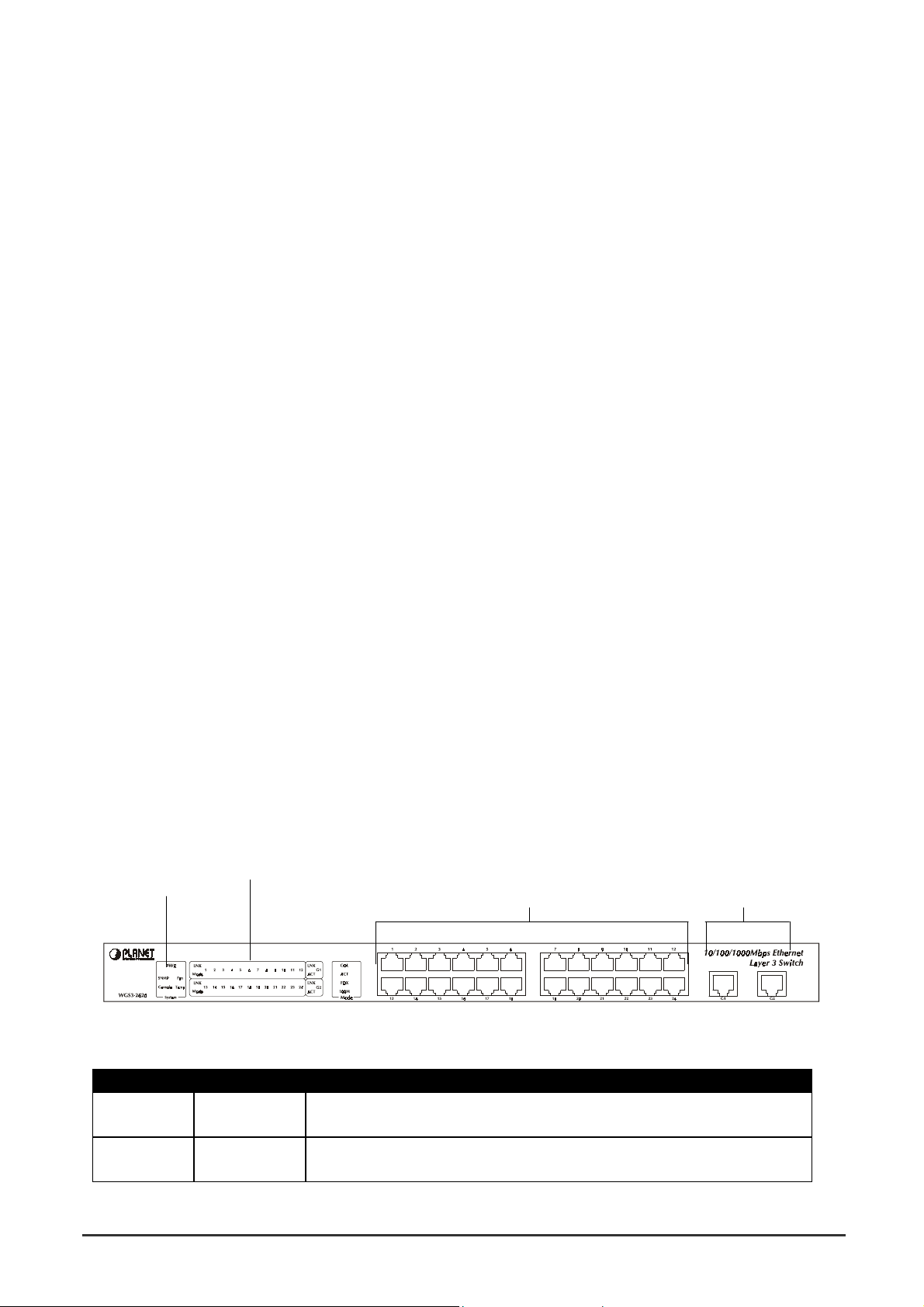
2.2.1 Front Panel of WGS3-2620
The front panel of the Switch has 24 RJ-45 ports for 10/100 Mbps in the middle. The port status LEDs
are indicated at the left. The 1000Base-T ports are situated at the right.
2.2.1.1 Front Panel Description
LEDs
System LEDs 10/100 RJ-45 Ports 1000Base-T Ports
2.2.1.2 Port Description
Ports # of Ports Description
10/100 24 These RJ-45 ports support network speeds of either 10Mbps or 100
Mbps, and can operate in half- or full-duplex modes.
1000Base-T 2 These two RJ-45 ports provide 1000Base-T network connection and
can operate on full-duplex modes.
WGS3 Layer 3 Switch User’s Manual
- 4 -
Page 13

2.2.1.3 LED Definition
The LEDs indicate the status of 10/100 Mbps Ethernet ports, 1000Base-T ports, Temp. Fan and Power.
LED State Indication
System
Power On Switch is receiving power.
SNMP On SNMP agent operational.
Console On RS-232 Console interface is operating
Fan*1 On One of the fans is failed and standby fan is running
Temp*2 On The internal temperature is equal to or higher than 60 degree C
10BaseT/100BaseTX Ports
LNK On Port has established a valid network connection
Mode*3
COL On Colli sion occurs on the port
ACT On Traffic is passing through the port
FDX On Been set to full duplex
100M On Connected on 100M speed
1000BaseT Ports
LNK On Port has established a valid network connection
ACT On Traffic is passing through the port
*1 There are two 4-inch fans and one 2-inch fan in the unit. Normally, one of the 4-inch fans and
2-inch fan is running. Another 4-inch fan is standby and not working. Once one of the two
running fans is failed, the standby fan will be drove to run and the Fan LED will light on.
*2 When the internal temperature is equal to or higher than 60 degree C, the standby fan will be drove
to run and the Temp LED will light on. Once the temperature is equal to or higher than 70 degree
C, the buzzer will sound. You can press the buzzer On/Off button to turn off the buzzer.
*3 Use the Mode button to select LED display mode.
2.2.2 Front Panel of WGS3-404
The front panel of the WGS3-404 has 4 RJ-45 ports for 10/100/1000 Mbps in the middle. The port status
LEDs are indicated at the left. The expansion modules are situated at the right.
2.2.2.1 Front Panel Description
LEDs
System LEDs
10/100/1000 Mbps ports Expansion Ports
WGS3 Layer 3 Switch User’s Manual
- 5 -
Page 14

2.2.2.2 Port Description
Ports # of Ports Description
10/100/1000 4 These RJ-45 port s su pport network speeds of 10, 100 or 1000 Mbps,
and can operate in full-duplex modes.
Expansion
Ports
4 These ports provide for the installation of one or two expansion
modules that establish a Fast or Gigabit Ethernet connection.
Note: You may install an 1000Base-SX or 1000Base-T expansion
module and use fiber optic or category 5 cabling.
2.2.2.3 LED Definition
The LEDs indicate the status of 10/100/1000 Mbps Ethernet ports, Over Heat, Fan Failure and Power.
The LEDs are explained in the following tables.
LED Color Indication
System
Power Green Lights to indicate switch is receiving power.
Fan Failure*1 Red Lights to indicate one of the fans is failed and standby fan is
running
Over Heat*2 Red Lights to indicate the internal temperature is equal to or higher
than 60 degree C
10/100/1000 Ports
Act Green Lights to indicate the Switch is actively receiving or sending the
data over the port.
FDX/COL Yellow Lights green to indicate that the port is operating in full-duplex
mode.
Blinks orange periodically to indicate that the connection is
experiencing collisions.
1000 Green Lights to indicate that the Switch is sending or receiving data at
1000 Mbps.
100 Green Lights to indicate that the Switch is sending or receiving data at
100 Mbps.
10 Yellow Lights to indicate that the Switch is sending or receiving data at
10 Mbps.
*1 There are two 4-inch fans and one 2-inch fan in the unit. Normally, one of the 4-inch fans and
2-inch fan is running. Another 4-inch fan is standby and not working. Once one of the two
running fans is failed, the standby fan will be drove to run and the Fan LED will light on.
*2 When the internal temperature is equal to or higher than 60 degree C, the standby fan will be
drove to run and the Temp LED will light on. Once the temperature is equal to or higher than 70
degree C, the buzzer will sound. You can press the buzzer On/Off button to turn off the buzzer.
2.2.3 Rear Panel of WGS3-2620 and WGS3-404
The rear panel of WGS3-2620 and WGS3-404 has a power connector, a Buzzer button and a console
port. The following picture shows their rear panel.
WGS3 Layer 3 Switch User’s Manual
- 6 -
Page 15
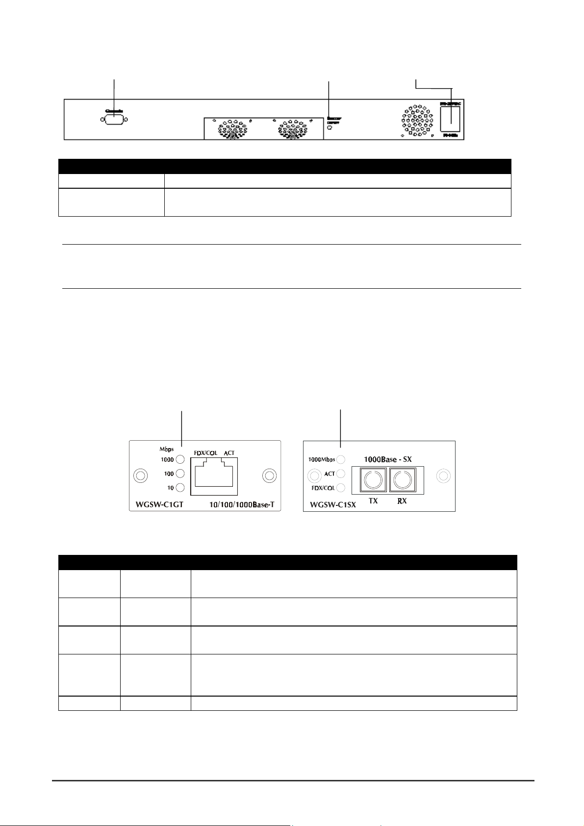
Console Buzzer Button Power
Port Function
Power This is where you will connect the AC power cord. 100~240VAC is allowed.
Console This is where you will connect to the RS-232 serial port on your PC for
configuring the management function, discussed in Chapter 3.
NOTE: To depress the Buzzer button will change the reaction of the buzzer. If the button is set to on,
the buzzer will ring as the system is under the status of overheat. Set to off, the buzzer will not
work even if the system overheats.
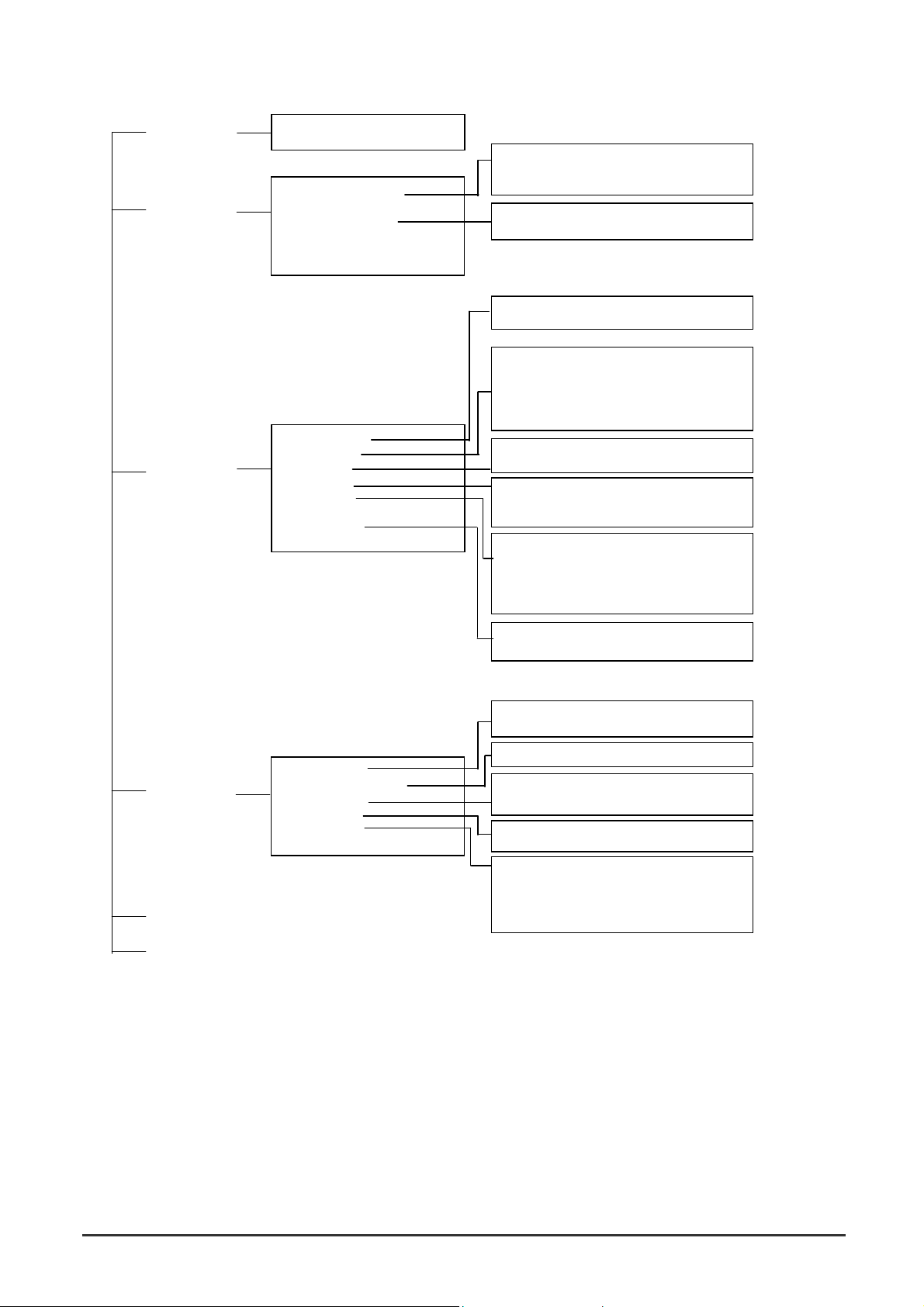
2.2.4 Module Hardware Description
WGS3-404 provides 4 slots for optional Gigabit copper and fiber module. The following picture show
that front panel of gigabit expansion module.
2.2.4.1 Panel Description
WGSW-C1GT Module Status LEDs WGSW-C1SX Module Status LEDs
2.2.4.2 WGSW-C1GT LED Definition
LED Color Function
1000 Green Lights to indicate that the Switch i s se nding or receiving data at 1000
Mbps.
100 Green Lights to indicate that the Switch is sending or receiving data at 100
Mbps.
10 Yellow Lights to indicate that the Switch is sending or receiving data at 10
Mbps.
FDX/COL Yellow Lights green to indicate that the port is operating in full-duplex mode.
Blinks orange periodically to indicate that the connection is experiencing
collisions.
Act Green Lights to indicate that the connection is acting.
WGS3 Layer 3 Switch User’s Manual
- 7 -
Page 16

2.2.4.3 WGSW-C1SX LED Definition
LED Color Function
1000 Green Lights to indicate that receiver of fibre port is in normal optical input
levels.
Act Green Lights to indicate that the connection is acting.
FDX/COL Yellow Lights to indicate that the port is operating at full duplex. This port does
not support half duplex.
2.3 Mounting the Switch
The switch can be placed directly on your desktop, or mounted in a rack. Before you start installing the
switch, make sure you can provide the right operating environment, including power requirements,
sufficient physical space, and proximity to other network devices that are to be connected. Verify the
following installation requirements:
• Power requirements: 100 to 240 V AC (+/-10%) at 50 to 60 Hz (+/-3Hz). The switch's power
supply automatically adjusts to the input voltage level.
• The switch should be located in a cool dry place, with at least 10 cm. (4 in.) of space on the
sides for ventilation.
• Place the switch out of direct sunlight, and away from heat sources or areas with a high amou nt
of electromagnetic interference.
• If you intend to mount the switch in a rack, make sure you have all the necessary mounting
screws, brackets, bolts and nuts, and the right tools.
• Check if network cables and connectors needed for installation are available.
2.3.1 Mounting Switches in a Rack
Please comply with the following instructions to ensure that your switch is securely mounted in the rack.
• Use a standard EIA 19-inch rack.
• Use the brackets and screws supplied in the rack mounting kit.
• Use a cross-head screwdriver to attach the brackets to the side of the switch.
• Position the switch in the rack by lining up the holes in the brackets with the appropriate holes on
the rack, and then use the supplied screws to mount the switch in the rack.
2.4 Connecting the Switch System
The transmission speed for each port on the switch is automatically set by the switch to match the
highest speed supported by the connected device. The transmission mode can be set for each port using
auto-negotiation (if also supported by the attached device). However, if the device attached to any port
on the switch does not support auto-negotiation, you can manually configure the transmission mode via
the console port on the rear panel, or via an in-band connection (including Telnet, the Web agent).
WGS3 Layer 3 Switch User’s Manual
- 8 -
Page 17

2.4.1 Making a Connection to an RJ-45 Port
The Gigabit copper ports support Auto-MDI/MDI-X. You can use straight-through or crossover
twisted-pair cable to connect any gigabit copper port on the switch to any device that uses a standard
network interface such as a workstation or server, or to a network intercon nection device such as a
bridge or router.
Prepare the network devices you wish to network. Make sure you have installed 10BASE-T,
100BASE-TX or 1000BASE-T network interface cards for connecting to the switch's RJ-45 ports.
Prepare straight-through shielded or unshielded twisted-pair cable s with RJ-45 plugs at both ends. Use
100-ohm Category 3, 4 or 5 cable for standard 10Mbps Ethernet connections, 100-ohm Category 5 cable
for 100Mbps Fast Ethernet connections, or Category 5e cable for 1000Mbps Gigabit Ethernet
connections.
Connect one end of the cable to the RJ-45 port of the network interface card, and the other end to any
available RJ-45 port on the switch. When inserting an RJ-45 plug, be sure the tab on the plug clicks
into position to ensure that it is properly seated. Using the switch in a stand-alone configuration, you can
network up to 26 end nodes
NOTE: Make sure each twisted-pair cable does not exceed 100 meters (328 feet). We advise using
Category 5e cable for all network connections to avoid any confusion or inco nvenience in the
future when you upgrade attached devices to Gigabit Ethernet.
Restrictions on Cascade Length - The IEEE 802.3 standard recommends restricting the number of
hubs (i.e., repeaters) cascaded via twisted-pair cable to 4; while IEEE 802.3u provides even stricter
recommendations for Fast Ethernet. Therefore, when cascading devices other than this switch, please
refer to the accompanying documentation for cascade restrictions. However, note that because switches
break up the path for connected devices into separate collision domains, you should not include the
switch or connected cabling in your calculations for cascade length involving other devices.
2.4.2 Making a Connection to an Gigabit Fiber Module
The modules are fitted with SC connectors. Please be sure you run cable from the Rx (Tx) port on the
module to the Tx (Rx) port on the target device. The length of Gigabit fiber optic cable for a single
switched link should not exceed 220m for 62.5/125 multimode fiber and 500 m for 50/125 multimode fiber.
However, power budget constraints must also be considered when calculatin g the maximum cable length
for your specific environment.
2.5 Powering On the Switch
Plug the power cord into the power socket on the rear of the switch, and the other end into a power
outlet.
Check the LED marked PWR on the front panel to see if it is on. The unit will automatically select the
setting that matches the connected input voltage. Therefore, no additional adjustments are necessary
when connecting it to any input voltage within the range marked on the rear panel.
The switch performs a self-diagnostic test upon power-on. (Note that this test takes about one minute to
complete.)
WGS3 Layer 3 Switch User’s Manual
- 9 -
Page 18

NOTE: The unit supports a "hot remove" feature which permits you to connect or disconnect
twisted-pair or fiber cables without powering off the switch and without disrupting the operation
of the devices attached to the switch. However, due to the spanning tree learning process, the
new attached device may takes about 30 seconds to be able to connect the other devices.
This period can be shortened by adjusting the spanning tree configuration.
2.6 Verifying System Operation
Verify that all attached devices have a valid connection. The switch monitors the link status for each port.
If any device is properly connected to the switch and transmitting a link beat signal, the Link indicator will
light up for the corresponding port. If the Link indicator fails to light when you connect a device to the
switch, check the following items:
Be sure all network cables and connectors are properly attached to the connected device and the switch.
See if your cable is functioning properly by using it for another port and attached device that displays
valid indications when connected to the network.
Be sure no twisted-pair cable exceeds 100 meters (328 feet).
WGS3 Layer 3 Switch User’s Manual
- 10 -
Page 19

Chapter 3. Switch Management
3.1 Configuration Options
For advanced management capability, the on-board management agent provides a menu-driven system
configuration program. This program can be accessed by serial port on the rear panel (out-of-band), or
by a Telnet connection over the network (in-band).
The management agent is based on SNMP (Simple Network Management Protocol). This SNMP agent
permits the switch to be managed from any PC in the network using in-band management software.
The management agent also includes an embedded HTTP Web agent. This Web agent can be accessed
using Microsoft Internet Explorer 4.0 or later from any computer attached to the network.
The system configuration program and the SNMP agent support management functions such as:
• Enable/disable any port
• Set the communication mode for any port
• Configure SNMP parameters
• Add ports to network VLANs
• Configure IP routing and multicast VLANs
• Display system information or statisti cs
• Configure the switch to join a Spanning Tree
• Download system firmware
3.2 Required Connections
3.2.1 Console Port (Out-of-Band) Connections
Attach a VT100 compatible terminal or a PC running a terminal emulation program to the seria l port on
the switch’ s rear panel. Use the null-modem cable provided with this package, or use a null modem
connection that complies with the wiring assignments shown in Appendix B of this manual.
When attaching to a PC, set terminal emulation type to VT100, specify the port used by your PC (i.e.,
COM 1~4), and then set communications to 8 data bits, 1 stop bit, no parity, and 19200 bps (for initial
configuration). Also be sure to set flow control to “none.” (Refer to “Configuring the Serial Port” for a
complete description of configuration options.)
NOTE: If the default settings for the management agent’s serial port have been modified and you are
having difficulty making a console connection, you can display or modify the current settings
using a Web browser as described under “Configuring the Serial Port”.
WGS3 Layer 3 Switch User’s Manual
- 11 -
Page 20

3.2.2 In-Band Connections
Prior to accessing the switch’ s on-board agent via a network connection, you must first config ure it with
a valid IP address, subnet mask, and default gateway (for Layer 2 mode) using an out-of-band
connection.
After configuring the switch’ s IP parameters, you can access the on-board configuration program from
anywhere within the attached network. The on-board configuration program can be accessed using
Telnet from any computer attached to the network. The switch can also be managed by any computer
using a Web browser (Internet Explorer 4.0 or above, or Netscape Navigator 4.0 or above), or from a
network computer using SNMP network management software.
Please note that:
• Each VLAN group can be assigned its own IP interface address. Therefore, if the port connected
to the management station has joined several VLANs, you can manage the switch via any of
these IP addresses.
• This switch supports four concurrent Telnet sessions.
• The on-board program only provides access to basic configuration functions. To access the full
range of SNMP management functions, you must use SNMP- based network management
software.
WGS3 Layer 3 Switch User’s Manual
- 12 -
Page 21

Chapter 4. Console Interface
4.1 Login Screen
Once a direct connection to the serial port or a Telnet connection is established, the login screen for the
on-board configuration program appears as shown below.
If this is your first time to log into the configuration program, then the default user names are “admin” with
no password. The administrator has Read/Write access to all configuratio n parameters and statistics.
You should define a new administrator password, record it and put it in a safe place. Select User
Configuration from the Management Setup Menu and enter a new password for the administrator. Note
that passwords can consist of up to 15 alphanumeric characters and are not case sensitive.
NOTE: You are allowed three attempts to enter the correct password; on the third failed attempt the
current connection is terminated.
After you enter the user name and password, you will have access to the system configuration program
illustrated by the following menu map:
WGS3 Layer 3 Switch User’s Manual
- 13 -
Page 22
System Information
Menu
Management Setup
Menu
Device Control
Menu
System Information
Switch Information
Network Configuration
Serial Port Configuration
SNMP Configuration
User Configuration
TFTP Download
Configuration File
(3)
(2)
(4)
System Mode
Layer 2 Menu
Bridge Menu
VLAN Menu
IP Menu
IGMP Snooping Configuration
Security Menu
Jumbo Packet Menu
(1)
IP Configuration
IP Connectivity Test (Ping)
HTTP Configuration
SNMP Communities
IP Trap Manager
(3)
Layer 2
Multilayer
Port Configuration
Mirror Port Configuration
Port Trunking Configuration
Static Unicast Address Configuration
Static Multicast Address Configuration
Bridge Configuration
Spanning Tree Port Configuration
VLAN Port Configuration
(1)
VLAN Table Configuration
Reset Address Table Mode
Subnet Configuration
Protocol Configuration
Static ARP Configuration
Static Route
Default Route
(3)
(4)
MAC Filtering Configuration
IP Filtering Configuration
Port Statistics
RMON Statistics
Unicast Address Table
Spanning Tree Bridge Information
Spanning Tree Port Information
VLAN Dynamic Registration Information
VLAN Forwarding Information
Subnet Information
ARP Table
Routing Table
Multicast Table
OSPF Table
Network Monitor
Menu
System Restart Menu
Exit
Port Statistics
Layer 2 Address Table
Bridge Menu
VLAN Menu
IP Menu
IP Multicast Registration Table
(2)
(1)
1. Displayed for layer 2 mode of WGS3-2620 only.
2. Displayed for multilayer mode of WGS3-2620 and WGS3-404 only
3. Displayed for WGS3-2620 only
4. Displayed for WGS3-404 only
(2)
WGS3 Layer 3 Switch User’s Manual
- 14 -
Page 23

4.2 Main Menu
With the system configuration program you can define system parameters, manage and control the
switch and all its ports, or monitor network conditions. The figure below of the Main Menu and the
following table briefly describe the selections available from this program.
NOTE: Options for the currently selected item are displayed in the highlighted area at the bottom of the
interface screen.
Menu Description
(Operation Mode) The text string in the top right corner of the screen shows if the switch is
operating as a Layer 2 switch or as a multilayer routing switch.
WGS3-404 is always operating as a multilayer routing switch and not
showing this message.
System Information Menu
System Information Provides basic system description, including contact information.
Switch Information Shows hardware/firmwa re version numbers, power status, and
expansion modules used in the switch.
Management Setup Menu
Network Configuration Includes IP Configuration *1, Ping facility, and HTTP (Web agent) setup.
Serial Port
Configuration
SNMP Configuration Activates authentication failure traps; and configures community access
Sets communication parameters for the serial port, including baud rate,
console time-out, and screen data refresh interval.
strings, and trap managers.
User Configuration Sets the user names and passwords for system access.
WGS3 Layer 3 Switch User’s Manual
- 15 -
Page 24

TFTP Download Downloads new version of firmware to update your system (in-band).
Configuration File Download the VLAN and routing configuration to a file or upload the
configuration file to the switch.
Device Control Menu
System Mode *3 Sets the switch to operate as a Layer 2 switch or as a multilayer routing
switch.
Layer 2 Menu Configures port communication mode, mirror ports, port trunking and
static unicast/multicast addre ss.
Bridge Menu Configures GMRP and GVRP for the bridge, and STA for the global
bridge or for specific ports.
VLAN Menu Configures VLAN settings for specific ports, and defines the port
membership for VLAN groups.
IGMP Snooping
Configuration
IP Menu
*1
*2
Configures the subnets for each VLAN group, global configuration for
Configures IGMP multicast filtering.
unicast and multicast protocols, BOOPP/DHCP relay, static ARP table
entries, static routes and the default route.
*2
Security Restrict access through MAC address or IP address
*4
Jumbo Packet Menu
Allows the switch to send jumbo packet up to 9k
Network Monitor Menu
Port Statistics Displays statistics on port traffic, including information from the
Interfaces Group, Ethernet-link MIB, and RMON MIB.
Layer 2 Address Table Contains tables for all unicast, static unicast, and static multicast
addresses, as well as the filter table for MAC addresses.
Bridge Menu Displays Spanning Tree Bridge and Port information
VLAN Menu Displays dynamic port registration information for VLANs, as well as all
VLAN forwarding information for static and dynamic assignment.
IP Multicast
Registration Table
*2
IP Menu
Displays all the IP subnets used on this switch, as well as the
Displays all the multicast groups active on this switch, including the
*1
multicast IP addresses and corresponding VLANs.
corresponding VLANs and ports. Also contains the ARP table, routing
table and multicast table.
System Restart
Restarts the system with options to reload factory defaults.
Menu
Exit Exits the configuration program.
*1: Only displays on WGS3-2620 when it is set to Layer 2 mode.
*2. Only displays on WGS3-404 and WGS3-2620 when it is set to multilayer mode.
*3. Only displays on WGS3-2620
*4. Only displays on WGS3-404
WGS3 Layer 3 Switch User’s Manual
- 16 -
Page 25

4.3 System Information Menu
Use the System Information Menu to display a basic description of the switch, including contact
information, and hardware/firmware versions.
Menu Description
System Information Provides basic system description, including contact information.
Switch Information Shows hardware/firmware version numbers, power status, and
expansion modules used in the switch.
WGS3 Layer 3 Switch User’s Manual
- 17 -
Page 26
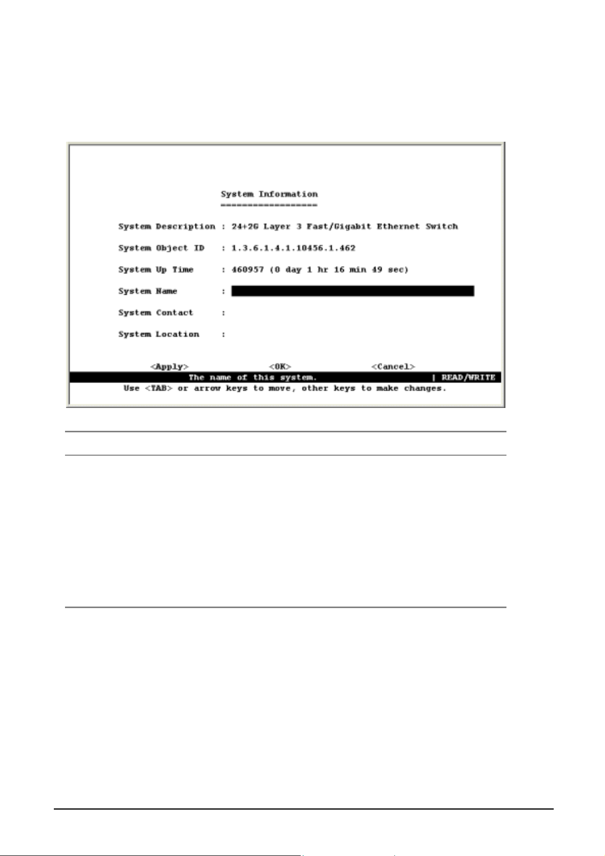
4.3.1 Displaying System Information
Use the System Information screen to display descriptive information about the switch, or for quick
system identification as shown in the following figure and table.
Parameter Description
System Description System hardware description.
System Object ID MIB II object identifier for switch’ s network management subsystem.
System Up Time Length of time the current management agent has been running. (Note
that the first value is centiseconds.)
System Name* Name assigned to the switch system.
System Contact* Contact person for the system.
System Location* Specifies the area or location where the system resides.
* Maximum string length is 99, but the screen only displays 45 characters. You can use the arrow
keys to browse the whole string.
WGS3 Layer 3 Switch User’s Manual
- 18 -
Page 27

4.3.2 Displaying Switch Version Information
Use the Switch Information screen to display hardware/firmware version numbers for the main board, as
well as the fan power status.
4.3.2.1 Switch Information of WGS3-2620
Parameter Description
Hardware Version Hardware version of the main board.
Firmware Version System firmware version in ROM.
Serial Number The serial number (MAC address) of the main board.
Port Number Number of ports on this switch.
Power Status Shows if power is active
Fan Power Status Shows if power to the fan is active or inactive.
G1 and G2 Information Shows the G1 and G2 connection type. It is always 1000Base-T on this
version
WGS3 Layer 3 Switch User’s Manual
- 19 -
Page 28

4.3.2.2 Switch Information of WGS3-404
Parameter Description
Hardware Version Hardware version of the main board.
Firmware Version System firmware version in ROM.
Serial Number The serial number (MAC address) of the main board.
Port Number Number of ports on this switch.
Packet Memory Size Shows memory size for packet buffer. It is always 6M bytes.
WGS3 Layer 3 Switch User’s Manual
- 20 -
Page 29

4.4 Management Setup Menu
After initially logging onto the system, adjust the communication parameters for your console to ensure a
reliable connection (Serial Port Configuration). Specify the IP addresses for the switch (Network
Configuration / IP Configuration), and then set the Administrator and User passwords ( User
Configuration). Remember to record them in a safe place. Also set the community string which controls
access to the on-board SNMP agent via in-band management software (SNMP Configuration). The items
provided by the Management Setup Menu are described in the following sections.
Menu Description
Network
Configuration
Serial Port
Configuration
SNMP Configuration Activates authentication failure traps; and configures communities and trap
User Configuration Sets the user names and passwords for system access.
TFTP Download Downloads new version of firmware to update your system (in-band).
Configuration File Download the configuration to a file or upload the configuration file to the
*1: Only displays on WGS3-2620 when it is set to Layer 2 mode.
Includes IP Configuration *1, Ping facility, and HTTP (Web agent) setup.
Sets communication parameters for the serial port, including baud rate,
console time-out, and screen data refresh interval.
managers.
switch.
WGS3 Layer 3 Switch User’s Manual
- 21 -
Page 30

4.4.1 Changing the Network Configuration
Use the Network Configuration menu to set the bootup option, configure the switch’ s Internet Protocol
(IP) parameters, or enable the on-board Web agent. The screen shown below is describe d in the
following table.
Parameter Description
IP Configuration* Screen used to set the bootup option, or configure the switch’s IP
parameters.
IP Connectivity Test (Ping) Screen used to test IP connectivity to a specified device.
HTTP Configuration Screen used to enable the Web agent.
* This menu does not appear on WGS3-404 or if the WGS3-2620 is set to multilayer mode. In this case,
you need to configure an IP interface for each VLAN that needs to connect to any device outside of its
own VLAN group. (See “Subnet Configuration”)
WGS3 Layer 3 Switch User’s Manual
- 22 -
Page 31

4.4.1.1 IP Configuration (Layer 2 Mode)
Use the IP Configuration screen to set the boot-up option, or configure the switch’s IP parameters. The
screen shown below is described in the following table.
WGS3 Layer 3 Switch User’s Manual
- 23 -
Page 32

Parameter Description
Interface Type Indicates IP over Ethernet.
IP Address IP address of the switch you are managing. The system supports SNMP over UDP/IP
transport protocol. In this environment, all systems on the Internet, such as network
interconnection devices and any PC accessing the agent module must have an IP
address. Valid IP addresses consist of four numbers, of 0 to 255, and separated by
periods. Anything outside of this format will not be accepted by the configuration
program.
Subnet Mask Subnet mask of the switch. This mask identifies the host address bits used for routing
to specific subnets.
Default Gateway Gateway used to pass trap messages from the system’ s agent to the management
station. Note that the gateway must be defined (when operating at Layer 2) if the
management station is located in a different IP segment.
IP State Specifies whether IP functionality is enabled via manual configuration, or set by Boot
Protocol (BOOTP).
Options include:
USER-CONFIG - IP functionality is enabled based on the default or user specified IP
Configuration. (This is the default setting.)
BOOTP Get IP - IP is enabled but will not function until a BOOTP reply has been
received. BOOTP requests will be periodically broadcasted by the switch in an effort
to learn its IP address. (BOOTP values can include the IP address, default gateway,
and subnet mask.)
VLAN ID The VLAN used for management access when “Mgmt VLAN” is selected. See the
next item.
Mgt. Access Specifies which VLAN have access right to its management interface. Options
include:
All VLANs – All VLANs have access right to its management interface. (This is the
default setting.)
Mgmt VLAN – Only the specified VLAN have access right to its management interface
WGS3 Layer 3 Switch User’s Manual
- 24 -
Page 33

4.4.1.2 IP Connectivity Test (Ping)
Use the IP Connectivity Test to see if another site on the Internet can be reached. The screen shown
below is described in the following table.
Parameter Description
IP Address IP address of the site you want to ping.
Test Times The number of ICMP echo requests to send to the specified site. Range: 1~1000
Success / Failure The number of times the specified site has responded or not to ping ing.
NOTE: The switch waits up to 10 seconds for a response to each ping.
WGS3 Layer 3 Switch User’s Manual
- 25 -
Page 34

4.4.1.3 HTTP Configuration
Use the HTTP Configuration screen to enable/disable the on-board Web agent.
NOTE: Port 80 is used for HTTP service.
WGS3 Layer 3 Switch User’s Manual
- 26 -
Page 35

4.4.2 Configuring the Serial Port
You can access the on-board configuration program by attaching a VT100 compatible device to the
switch’s serial port. (For more information on connecting to this port, see “Required Connections” on
Section 3.2) The communication parameters for this port can be accessed from the Serial Port
Configuration screen shown below and described in the following table.
WGS3 Layer 3 Switch User’s Manual
- 27 -
Page 36

Parameter Default Description
Management Mode Console Mode Indicates that the port settings are for direct console
connection.
Baud Rate 19200 The rate at which data is sent between devices. Options :
9600, 19200 and 38400 baud.
Data Bits 8 bits Sets the data bits of the RS-232 port. Options : 7, 8
Stop Bits 1 bit Sets the stop bits of the RS-232 port. Options : 1, 2
Parity None Sets the parity of the RS-232 port. Options :
none/odd/even
Time-Out 0 If no input is received from the attached device after this
interval, the current session is automatically closed.
Range : 0 - 100 minutes; where 0 indicates disabled
Auto Refresh 10 second Sets the interval before a console session will auto
refresh the console information, such as Spanning Tree
Information, Port Configuration, Port Statistics, and
RMON Statistics. Range : 0, or 5-255 seconds; where 0
indicates disabled
WGS3 Layer 3 Switch User’s Manual
- 28 -
Page 37

4.4.3 Assigning SNMP Parameters
Use the SNMP Configuration screen to display and modify parameters for the Simple Network
Management Protocol (SNMP). The switch includes an on-board SNMP agent which monitors the status
of its hardware, as well as the traffic passing through its ports. A computer attached to the network,
called a Network Management Station (NMS), can be used to access this information. Access rights to
the on-board agent are controlled by community strings. To communicate with the switch, the NMS must
first submit a valid community string for authentication. The options for configuring community strings and
related trap functions are described in the following sections.
Parameter Description
Send
Authentication Fail
Traps
SNMP
Communities
IP Trap Managers Specifies management stations that will receive authentication failure messages or
Issue a trap message to specified IP trap managers whenever authentication of an
SNMP request fails. (The default is enabled.)
Assigns SNMP access based on specified strings.
other trap messages from the switch.
WGS3 Layer 3 Switch User’s Manual
- 29 -
Page 38

4.4.3.1 Configuring Community Names
The following figure and table describe how to configure the community strings authorized for
management access. Up to 5 community names may be entered.
Parameter Description
Community Name A community entry authorized for management access. Maximum string length :
19 characters
Access Management access is restricted to Read Only or Read/ Write.
Status Sets administrative status of entry to enabled or disabled.
NOTE: The default community strings are displayed on the screen.
WGS3 Layer 3 Switch User’s Manual
- 30 -
Page 39

4.4.3.2 Configuring IP Trap Managers
The following figure and table describe how to specify management stations that will receive
authentication failure messages or other trap messages from the switch. Up to 5 trap managers may be
entered.
Parameter Description
IP Address IP address of the trap manager.
Community
Name
Status Sets administrative status of selected entry to enabled or di sabled.
A community specified for trap management access.
WGS3 Layer 3 Switch User’s Manual
- 31 -
Page 40

4.4.4 User Login Configuration
Use the User Configuration menu to restrict management access based on specified user names and
passwords. There are two user types, Administrator and Guest. Only the Administrator has write access
for parameters governing the SNMP agent. You should therefore assign a user name and password to
the Administrator as soon as possible, and store it in a safe place. (If for some reason your password is
lost, or you cannot gain access to the System Configuration Program, contact Technical Support for
assistance.) The parameters shown on this screen are indicated in the following figure and table.
Parameter Description
User Name Specifies a user authorized management access to the switch via the console,
Telnet or HTTP.
Access Right There are two options. ADMIN: Read/Write for all screens. GUEST: Read Only
for all screens.
Console Authorizes management via the console.
Telnet Authorizes management via Telnet.
HTTP Authorizes management via HTTP (that is, Microsoft Internet Explorer 4.0 or later
version. It does not support Netscape currently).
WGS3 Layer 3 Switch User’s Manual
- 32 -
Page 41

To add a new user, select <Add>. When you add a user, the following screen is displayed.
Parameter Description
User Name* Specifies a user authorized management access to the switch via the console,
Telnet or HTTP.
Password* Passwords can consist of up to 11 alphanumeric characters and are not case
sensitive.
Access Right ADMIN: Read/Write for all screens. GUEST: Read Only for all screens.
Console Access Authorizes management via the console.
Telnet Access Authorizes management via Telnet.
HTTP Access Authorizes management via HTTP (that is, Microsoft Internet Explorer 4.0 or late r
version).
* These entries can consist of up to 15 alphanumeric characters and are not case sensitive.
WGS3 Layer 3 Switch User’s Manual
- 33 -
Page 42

4.4.5 Downloading System Software
Use the TFTP Download menu to load software updates to permanent flash ROM in the switch. The
download file should be a 3 binary file or image file; otherwise the agent will not accept it. The success of
the download operation depends on the accessibility of the TFTP server and the quality of the network
connection. After downloading the new software, the agent will automatically restart itself. Parameters
shown on this screen are indicated in the following figure and table.
Parameter Description
Download Server IP IP address of a TFTP server.
Download Filename The binary file to download.
Download Option Specify the file to be Runtime code or POST code.
NOTE: You can also download firmware using the Web agent or by a direct console connection after a
restart.
WGS3 Layer 3 Switch User’s Manual
- 34 -
Page 43

4.4.6 Saving or Restoring the System Configuration
Use the Configuration File menu to save the switch configuration settings to a file on a TFTP client. The
file can be later downloaded to the switch to restore the switch’s settings. The success of the operation
depends on the accessibility of the TFTP client and the quality of the network connection. Parameters
shown on this screen are indicated in the following figure and table.
Parameter Description
Station IP IP address of a PC running TFTP client software.
Operation Download from switch – Downloads the current switch configuration to a file
on the client PC.
Upload to switch – Uploads a configuration file to the switch from the client
PC.
WGS3 Layer 3 Switch User’s Manual
- 35 -
Page 44

Saving and restoring switch configuration settings can be initiated by using any TFTP client utility, such
as the command line utility included in Windows NT/2000/XP. For example, using Windows NT, from a
DOS window command prompt, enter the TFTP command in the form:
TFTP [-i] host [GET : PUT] source [destination]
To transfer a file –
On Switch: Specify the IP address of the TFTP client, and select “Download from switch” or “Upload to
Switch.” Then select <Start> from the menu to start.
On TFTP Client: Set the mode to <binary>, specify the IP address of the target switch and the directory
path / name of the file to transfer. Then start transferring the configuration from the TFTP client or the
switch and wait until the transfer completes.
For example, type “tftp -i 203.70.249.118 GET source wgs3.txt” on Windows 2000’s command prompt to
download switch’s configuration and type “tftp –i 203.70.249.118 PUT wgs3.txt” to upload the
configuration file to switch.
WGS3 Layer 3 Switch User’s Manual
- 36 -
Page 45

4.5 Device Control Menu
The Device Control menu is used to control a broad range of functions, including port mode, port
mirroring, port trunking, Spanning Tree, Virtual LANs, IP subnets, multicast filtering, and routing protocols.
Each of the setup screens provided by these configuration menus is described in the following sections.
Menu Description
System Mode Sets the switch to operate as a Layer 2 switch or as a multilayer routing switch.
Layer 2 Menu Configures port communication mode, mirror ports, and port trunking.
Bridge Menu Configures the Spanning Tree Protocol for the bridge or for specific ports,
GMRP and GVRP for automatic registration of multicast and VLAN groups,
traffic class priority threshold, and address aging time.
VLAN Menu Configures V LAN settings for specific ports, and defines the port membership
for VLAN groups.
IGMP Snooping
Configuration
IP Menu
*1
*2
Configures the subnets for each VLAN group, global configuration for unicast
Security Restrict access through MAC address or IP address
Configures IGMP multicast filtering.
and multicast routing protocols, IGMP snooping
*2
Jumbo Packet Menu Allow the WGS3-404 to send up to 9k jumbo packet
1: Only displayed for Layer 2 mode of WGS3-2620.
2: Only displayed for Multilayer mode of WGS3-2620 and WGS3-404.
3: Only displayed for WGS3-404
WGS3 Layer 3 Switch User’s Manual
- 37 -
Page 46

4.5.1 Setting the System Operation Mode
WGS3-2620 can be set to operate as a Layer 2 switch, making all filtering and forwarding decisions
based strictly on MAC addresses. Or it can be set to operate as a multilayer routing switch, whereby it
switches packets for all non-IP protocols (such as NetBUEI, NetWare or AppleTalk) based on MAC
addresses, and routes all IP packets based on the specified routing protocol. The System Mo de menu is
shown below. Note that the switch will be automatically rebooted whenever the system operation mode is
changed.
Parameter Description
Layer 2 Filtering and forwarding decision will be based on MAC addresses for all protocol
traffic.
Multilayer Switching based on MAC addresses will be used for all non-IP protocol traffic, and
routing will be used for all IP protocol traffic.
NOTE: When the switch is set to multilayer mode, the IP menus are enabled, and the “IP Configuration
(Layer 2 Mode)” menu is disabled. When operating in multilayer mode, you should configure a n
IP interface for each VLAN that needs to communicate with any device outside of the VLAN.
(See “Subnet Configuration”)
WGS3 Layer 3 Switch User’s Manual
- 38 -
Page 47

4.5.2 Layer 2 Menu
The Layer 2 menu contains options for port configuration, port mirroring, port trunking and static
unicast/multicast address configuration. These menu options are described in the following sections.
Menu Description
Port Configuration Enables any port, enables/disables flow control, and sets
communication mode to auto-negotiation, full duplex or half duplex.
Mirror Port Configuration Sets the source and target ports for mirroring.
Port Trunking Configuration Specifies ports to group into aggregate trunks.
Static Unicast Address
Configuration
Static Multicast Address
Configuration
Used to manually configure host MAC addresses in the unicast table.
Used to manually configure host MAC addresses in the multicast
table.
WGS3 Layer 3 Switch User’s Manual
- 39 -
Page 48

4.5.2.1 Configuring Port Parameters
Use the Port Configuration menu to display or set communication parameters for any port on the switch,
including administrative status, auto-negotiation, default communication speed and duplex mode, as well
as flow control in use.
Parameter Default Description
Link Status Indicates if the port has a valid connection to an external device.
Admin Status Enabled Allows you to disable a port due to abnormal behavior (e.g., excessive
collisions), and then re-enable it after the problem has been resolved.
You may also disable a port for security reasons.
Auto Negotiate Enabled Enables or disables auto-negotiation for port speed, duplex mode, and
flow control.
Default Type 10HDX If auto-negotiation is disabled, the port will be set to the indicated speed
and duplex mode.
Current Type Indicates the current speed and duplex mode.
Flow Control Off Used to enable or disable flow control. Flow control can eliminate frame
loss by “blocking” traffic from end stations or segments connected
directly to the switch when its buffers fill. When enabled, back pressure
is used for half duplex and IEEE 802.3x for full duplex. Note that flow
control should not be used if a port is connected to a hub.
Jack Type RJ-45 or SC Shows the jack type for each port.
WGS3 Layer 3 Switch User’s Manual
- 40 -
Page 49

4.5.2.2 Using a Mirror Port for Analysis
You can mirror traffic from any source port to a target port for real-time analysis. You can then attach a
logic analyzer or RMON probe to the target port and study the traffic crossing the source port in a
completely unobtrusive manner. When mirroring port traffic, note that the target port must be included in
the same VLAN as the source port. (See “Configuring Virtual LANs”)
You can use the Port Mirror Configuration screen to mirror one or more ports to the monitor port as
shown below.
Parameter Description
Port Mirroring Enables or disables the mirror function.
Mirrored Ports (Tx/Rx) The port whose transmitted or received traffic will be mirrored. Press Add
to specify mirrored ports.
Monitor Port The port that will duplicate the transmitted or received traffic appearing on
the mirrored port.
NOTE: You can mirror multiple ports to a single port to view traffic on WGS3-2620. However, note
that some packets may be dropped for moderate to heavy loading.
WGS3 Layer 3 Switch User’s Manual
- 41 -
Page 50

4.5.2.3 Configuring Port Trunks
Ports can be combined into an aggregate link to increase the bandwidth of a network connection or
ensure fault recovery. You can configure trunks between any two switches. The ports on this switch can
be grouped into a trunk consisting of two, four or eight ports, creating an aggregate bandwidth to 400,
800, 1600, 4000 or 8000 Mbps when operating at full duplex. Besides balancing the load across each
port in the trunk, the additional ports provide redundancy by taking over the load if another port in the
trunk should fail. However, before making any physical connections between devices, use the Port
Trunking Configuration menu to specify the trunk on the devices at both ends. When using a port trunk,
remember that::
• The ports that can be assigned to the same trunk on WGS3-2620 are listed below:
Two ports as a trunk
<<13, 01>> <<14, 02>> <<15, 03>> <<16, 04>>
<<17, 05>> <<18, 06>> <<19, 07>> <<20, 08>>
<<21, 09>> <<22, 10>> <<23, 11>> <<24, 12>>
Four ports as a trunk
<<13, 01, 14, 02>> <<15, 03, 16, 04>>
<<17, 05, 18, 06>> <<19, 07, 20, 08>>
<<21, 09, 22, 10>> <<23, 11, 24, 12>>
Eight ports as a trunk
<<13, 01, 14, 02, 15, 03, 16, 04>>
<<17, 05, 18, 06, 19, 07, 20, 08>>
<<21, 09, 22, 10, 23, 11, 24, 12>>
Gigabit Ethernet Ports as a trunk
<<25, 26>>
• The ports that can be assigned to the same trunk on WGS3-404 are listed below:
Two ports as a trunk
<<1, 2>> <<3, 4>> <<5, 6>> <<7, 8>>
Four ports as a trunk
<<1, 2, 3, 4>> <<5, 6, 7, 8>>
• Ports can only be assigned to one trunk.
• The ports at both ends of a connection must be configured as trunk ports.
• The ports at both ends of a trunk must be configured in an identical manner, including
communication mode, and VLAN assignments.
• None of the ports in a trunk can be configured as a mirror or monitor port.
• All the ports in a trunk have to be treated as a whole when moved from/to, added or deleted from
a VLAN.
• The Spanning Tree Algorithm will treat all the ports in a trunk as a whole.
• Enable the trunk prior to connecting any cable between the switches to avoid creating a loop.
WGS3 Layer 3 Switch User’s Manual
- 42 -
Page 51

You can use the Port Trunking Configuration screen to set up port trunks as shown below:
Parameter Description
Trunk# The trunk identifier.
Port Count Trunks can contain 2, 4 or 8 ports.
Port Number The ports assigned to each trunk.
To add a trunk, press <Add>. To delete a trunk, highlight the required entry and press Enter. Before
disconnecting a port trunk, take the following steps:
• Before removing a port trunk via the configuration menu, you must disable all the ports in the
trunk or remove all the network cables. Otherwise, a loop may be created.
• To disable a single link within a port trunk, you should first remove th e network cable, and then
disable both ends of the link via the configuration menu. This allows the traffic passing across
that link to be automatically distributed to the other links in the trunk, without losing any
significant amount of traffic.
WGS3 Layer 3 Switch User’s Manual
- 43 -
Page 52

4.5.2.4 Configuring the Static Unicast Address Table
The Static Unicast Address Table can be used to assign the MAC address for a host device to a specific
port on this switch. Static unicast addresses are never aged out, and cannot be learned on another port.
If any packets with a source address specified in this table enter another port, they will be dropped. The
Static Unicast Address Table is described in the following figure and table.
Parameter Description
Address The MAC address of a host device attached to this switch.
Port The switch port the host device is attached to.
NOTE: To assign a MAC address to a specific port, use <Add>. To delete o r modify an address,
highlight it with the cursor and press Enter. To scroll through the address table, use the <Next
Page> and <Prev Page> buttons. To display a specific page, set the page number in the Page
field and then press <Apply>.
WGS3 Layer 3 Switch User’s Manual
- 44 -
Page 53

4.5.2.5 Configuring the Static Multicast Address Table
The Static Multicast Address Table can be used to assign a destination MAC address (and the
corresponding ports) to the VLAN group used for a specific multicast service. Static multicast addresses
are never aged out, and traffic with these addresses can only be forwarded to ports specified in this
table.
Parameter Description
VLAN The VLAN corresponding to this multicast service.
Address The destination MAC address for a multicast service.
Port The ports to which this multicast traffic can be forwarded.
NOTE: To assign a destination MAC address to one or more ports, use <Add>. To delete or modify an
address, highlight it with the cursor and press Enter. To scroll through the address table, use
the <Next Page> and <Prev Page> buttons. To display a specific page, set the page number in
the Page field and then press <Apply>.
WGS3 Layer 3 Switch User’s Manual
- 45 -
Page 54

4.5.3 Using the Bridge Menu
The Bridge menu is used to display or configure settings for the Spanning Tree Algorithm, as well as the
global bridge settings for GMRP (GARP Multicast Registration Protocol) and GVRP (GARP VLAN
Registration Protocol), traffic classes priority threshold, and address aging time.
The Spanning Tree Algorithm can be used to detect and disable network loops, and to provid e backup
links between switches, bridges or routers. This allows the switch to interact with other bridging devices
(that is, an STA-compliant switch, bridge or router) in your network to ensure that only one route exists
between any two stations on the network, and provide backup links that automatically take over when a
primary link goes down. For a more detailed description of how to use this algorithm, refer to “Spanning
Tree Algorithm” on Chapter “Advanced Topics”.
Menu Description
Bridge Configuration Contains global bridge settings for STA (including bridge priority, hello time,
forward delay, maximum message age), GMRP, GVRP, traffic class priority
threshold, and address aging time.
Spanning Tree Port
Configuration
Contains STA settings for individual ports, including port priority, path cost, and
fast forwarding
WGS3 Layer 3 Switch User’s Manual
- 46 -
Page 55

4.5.3.1 Configuring Global Bridge Settings
The following figure and table describe bridge configuration for STA, GMRP, GVRP, priority threshold,
and address aging time.
Parameter Default Description
Spanning Tree Enabled Enable this parameter to participate in a STA compliant network.
Bridge Priority 32,768 Bridge priority is used in selecting the root device, root port, and
designated port. The device with the highest priority becomes the STA
root device. However, if all devices have the same priority, the device
with the lowest MAC address will then become the root device.
Enter a value from 0 - 65535.
Remember that the lower the numeric value, the higher the priority.
Hello Time
2 Time interval (in seconds) at which the root device transmits a
configuration message.
The minimum value is 1.
The maximum value is the lower of 10 or
[(Max. Message Age / 2) -1].
WGS3 Layer 3 Switch User’s Manual
- 47 -
Page 56

Forward Delay 15 The maximum time (in seconds) the root device will wait before
changing states (that is, listening to learning to forwarding). This delay
is required because every device must receive information about
topology changes before it starts to forward frames. In addition, each
port needs time to listen for conflicting information that would make it
return to a blocking state; otherwise, temporary data loops might result.
The maximum value is 30.
The minimum value is the higher of 4 or
[(Max. Message Age / 2) + 1].
Max (Message)
Age
GMRP
*1
Disabled GARP Multicast Registration Protocol (GMRP) allows network devices
20 The maximum time (in seconds) a device can wait without receiving a
configuration message before attempting to reconfigure. All device
ports (except for designated ports) should receive configuration
messages at regular intervals. Any port that ages out STA information
(provided in the last configuration message) becomes the designated
port for the attached LAN. If it is a root port, a new root port is selected
from among the device ports attached to the network.
The minimum value is
the higher of 6 or [2 x (Hello Time + 1)].
The maximum value is
the lower of 40 or [2 x (Forward Delay - 1)].
to register end stations with multicast groups. If GMRP is globally
enabled for the switch, then you can individually enable or disable
GMRP for a specific port. See “4.5.4.1 VLAN Port Configuration”.
IGMP and IGMP Snooping also provide multicast filtering. For
multilayer mode, the full IGMP protocol set is automatically
enabled/disabled along with DVMRP. (See “6.4.2 IGMP Protocol”,and
“4.5.5 Configuring IGMP Snooping”.)
GVRP Disabled GARP VLAN Registration Protocol (GVRP) defines a way for switches
to exchange VLAN information in order to register VLAN members on
ports across the network. This function should be enabled to permit
automatic VLAN registration, and to support VLANs which extend
beyond the local switch.
If GVRP is globally enabled for the switch, then you can individually
enable or disable GVRP for a specific port. See “4.5.4.1 VLAN Port
Configuration”.
Priority
Threshold
4 WGS3-2620 supports Quality of Service (QoS) by using two p riority
*1
queues, with Weighted Fair Queuing for each port. Up to 8 separate
traffic classes are defined in IEEE 802.1p. So any packets with a
priority equal to or higher than this threshold are placed in the high
priority queue. You can use “4.5.4.1 VLAN Port Configuration” to
configure the default priority for each port.
WGS3 Layer 3 Switch User’s Manual
- 48 -
Page 57

High/Medium/
Low Priority
6/4/2 WGS3-404 supports Quality of Service (QoS) by using four priority
*2
queues (High, Medium, Low and Lowest), with Weighted Fair Q ueuing
for each port. Up to 8 separate traffic classes are defined in IEEE
802.1p. So any packets with a priority equal to or higher than High
Priority (default is 6) are placed in the high priority queue and so do
others. Any packets with a priority lower than Low Priority (default is
2) are placed in the lowest priority queue. You can use “4.5.4.1 VLAN
Port Configuration” to configure the default priority for each port.
Aging Time 300 Time-out period in seconds for aging out dynamically learned MAC
addresses information.
Range: 10 - 1000000 seconds
1: Only displayed on WGS3-2620.
2: Only displayed on WGS3-404
WGS3 Layer 3 Switch User’s Manual
- 49 -
Page 58

4.5.3.2 Configuring STA for Ports
The following figure and table describe port STA configuration.
WGS3 Layer 3 Switch User’s Manual
- 50 -
Page 59

Parameter Default Description
Type
Priority 128 Define s the priority for the use of a port in the STA algorithm. If the path
(Path) Cost 100/19/4 This parameter is used by the STA algorithm to determine the best path
Shows port type as:
100TX : 10BASE-T / 100BASE-TX
1000T : 1000BASE-T
1000FX: 1000Base-SX or 1000Base-LX
cost for all ports on a switch are the same, the port with the highest
priority (that is, lowest value) will be configured as an active link in the
Spanning Tree. Where more than one port is assigned the highest
priority, the port with lowest numeric identifier will be enabled. The range
is 0 - 255.
between devices. Therefore, lower values should be assigned to ports
attached to faster media, and higher values assigned to ports with
slower media. (Path cost takes precedence over port priority.)
The default and recommended range is:
Ethernet: 100 (50~600)
Fast Ethernet: 19 (10~60)
Gigabit Ethernet: 4 (3~10)
The full range is 0 - 65535.
Fast
Forwarding
NOTE: Since end-nodes cannot cause forwarding loops, they can pass through the Spanning Tree
state changes more quickly than allowed by standard convergence time. Fast Forwarding can
achieve quicker convergence for end-node workstations and servers, and also o v ercome other
STA related time-out problems. (Remember that Fast Forwarding should only be enabled for
ports connected to an end-node device.)
Disabled This parameter is used to enable/disabled the Fast Spanning Tree mode
for the selected port. In this mode, ports skip the Blocked, Listening and
Learning states and proceed straight to Forwarding.
WGS3 Layer 3 Switch User’s Manual
- 51 -
Page 60

4.5.4 Configuring Virtual LANs
You can use the VLAN configuration menu to assign any port on the switch to any of up to 256 Virtual
LAN groups. In conventional networks with routers, broadcast traffic is split up into separate domains.
Switches do not inherently support broadcast domains. This can lead to broadcast storms in large
networks that handle traffic such as IPX or NetBEUI. By using IEEE 802.1Q compliant VLANs, you can
organize any group of network nodes into separate broadcast domains, confining broadcast traffic to the
originating group. This also provides a more secure and cleaner network environment. For more
information on how to use VLANs, see “6.3 Virtual LANs”. The VLAN configuration screens are described
in the following sections.
4.5.4.1 VLAN Port Configuration
You can use the VLAN Port Configuration screen to configure GARP, the default VLAN identifier, default
port priority, VLAN tagging on the attached link, GVRP and GMRP status, and filtering of incoming
frames for VLAN groups to which this port does not belong.
WGS3 Layer 3 Switch User’s Manual
- 52 -
Page 61

Parameter Default Description
GARP *1
Group Address Registration Protocol is used by GVRP and GMRP to
register or deregister client attributes for client services within a bridged
LAN.
Join Time 20 The interval (centiseconds) between transmitting requests/queries to
participate in a group.
Leave Time 60 The interval (centiseconds) a port waits before leaving a group. This
time should be set to more than twice the Join Time. This ensures that
after a Leave or LeaveAll message has been issued, the applicants
can re-join before the port actually leaves the group.
Leave All Time 1000 The interval (centiseconds) between sending out a LeaveAll query
message for group participants and the port leaving the group. This
interval should be considerably larger than the Leave Time to minimize
the amount of traffic generated by nodes rejoining the group.
1: The default values for the GARP timers are independent of the media access method or data rate.
These values should not changed unless you are experiencing some difficulties with GMRP or GVRP
registration/deregistration.
Parameter Default Description
VLAN and Priority These fields set the default values for VLANs, port priority, GVRP and
GMRP.
Port VID 1 The VLAN ID assigned to untagged frames received on this port.
Port Default
Priority
*2
0 Set the default ingress priority to any value beneath the priority threshold
to specify the low priority queue, or to any value equal to or above this
threshold to specify the high priority queue.
VLAN Tagging
*3
Layer 2 -
Indicates whether or not VLAN tags will be included on frames passing
through this port. The options include:
Rx All,
Rx All: Accepts all frames, tagged or untagged.
Tx All
Rx Untag: Only accepts untagged frames.
Multilayer -
Tx All: If PVID and frame tag are same, sends tagged frame,
Rx All,
Tx Untag
otherwise sends untagged.
Tx Untag: Sends only untagged frames.
2: The switch supports Quality of Service (QoS) by using two or four priority queues, with Weighted Fair
Queuing for each port. Inbound frames that do not have VLAN tags are tagged with the input port’ s
default ingress user priority, and then placed in the appropriate priority queue at the output port. The
default priority for all ingress ports is zero. Therefore, any inbound frames that do not have priority tags
will be placed in the low priority queue of the output port. (Note that if the output port is an untagged
WGS3 Layer 3 Switch User’s Manual
- 53 -
Page 62

member of the associated VLAN, these frames are stripped of all VLAN tags prior to transmission.)
3: If you want to create a small port-based VLAN for just one or two switches, you can assign ports to the
same untagged VLAN (and use a separate connection where a VLAN crosses the switches). However,
to participate in a VLAN group that extends beyond this switch, we recommend using the VLAN ID for
that group (using VLAN tagging for Layer 2 mode, or a common PVID for multilayer mode).
When operating the switch in Layer 2 mode, ports assigned to a large VLAN group that crosses seve ral
switches must use VLAN tagging. But when operating in multilayer mode, this switch does not currently
support tagging, so you should set the PVID to the same value at both ends of the link (if the device you
are attaching to is VLAN-aware), and configure an IP interface for this VLAN if you need to connect it to
other group.
This parameter is for WGS3-2620 only. WGS3-404’s default setting is Rx All and use VLAN Table
Configuration for Tx.
Parameter Default Description
GVRP Enabled Enables or disables GVRP for this port. When disabled, any GVRP
packets received on this port will be discarded and no GVRP registrations
will be propagated from other ports.
Note that GVRP must be enabled globally for the switch before this
setting can take effect. (See “4.5.3.1 Configuring Global Bridge Settings”)
GMRP*4 Enabled Enables or disables GMRP for this port. When enabled, this port will allow
end stations to register with multicast groups using GMRP. Note that
GMRP must be enabled for the switch before this setting can take effect.
IGMP and IGMP Snooping also provide multicast filtering. (See “6.4.2
IGMP Protocol”)
Ingress
Filtering
*5
Disabled If enabled, incoming frames for VLANs which do not include this ingress
port in their member set will be discarded at the ingress port.
4: Only displayed on WGS3-2620.
5: This control does not affect VLAN independent BPDU frames, such as GVRP or STP. However, they
do affect VLAN dependent BPDU frames, such as GMRP.
WGS3 Layer 3 Switch User’s Manual
- 54 -
Page 63

4.5.4.2 VLAN Table Configuration
Use this screen to create a new VLAN or modify the settings for an existing VLAN.
The VLAN Table Configuration of WGS3-2620 and WGS3-404 are slightly different. For WGS3-2620,
the VLAN Table Configuration is as the following:
The configuration parameter for WGS3-2620 is as the following:
Parameter Description
VLAN The ID for the VLAN currently displayed. Range: 1-4094
Port Port entries may be marked as:
- : (Normal) Uses GVRP to determine port membership.
S : (Static) Adds port as a static entry. GVRP protocol is disabled.
R : (Registration Fixed) Adds port as a static entry. GVRP protocol messages are still
forwarded through this port.
X : (Forbidden) Disables GVRP for this VLAN on the specified port.
If a removed port is no longer assigned to any other group as an untagged port, it will
automatically be assigned to VLAN group 1 as untagged.
NOTE: Use the <Next Page> and <Prev Page> buttons to scroll through the table. To display a specific
page, set the page number in the Page field and press <Apply>. To modify a VLAN group,
highlight the entry in the table and press Enter. To add a VLAN group, press <Add>.
WGS3 Layer 3 Switch User’s Manual
- 55 -
Page 64

The VLAN Table Configuration of WGS3-404 is as the following:
Parameter Description
VLAN The ID for the VLAN currently displayed.
Range: 1-4094
MEMBERS Port entries may be marked as:
- : (Normal) Uses GVRP to determine port membership.
S : (Static) Adds port as a static entry. GVRP protocol is disabled.
R : (Registration Fixed) Adds port as a static entry. GVRP protocol messages are still
forwarded through this port.
X : (Forbidden) Disables GVRP for this VLAN on the specified port.
If a removed port is no longer assigned to any other group as an untagged port, it will
automatically be assigned to VLAN group 1 as untagged.
UNTAG Specify the outbound packets for this VLAN on this port should be tagged or
untagged.
U: The outbound packets for this VLAN on this port should be untagged.
T: The outbound packets for this VLAN on this port should be tagged.
WGS3 Layer 3 Switch User’s Manual
- 56 -
Page 65

4.5.4.3 Reset Address Table Mode
WGS3-404 provide two address table modes, SVL (Shared VLAN Learning) and IVL (Independent VLAN
Learning).
SVL: Configuration and operation of the MAC address learning process with the same MAC address
table for all VLANs. If an individual MAC Address is learned in one VLAN, that learned information is
used in forwarding decisions taken for that address relative to all other VLANs. SVL is suitable when
you need to have asymmetric VLANs. Under normal circumstances, a pair of devices communicating in a
VLAN environment will both send and receive using the same VLAN. However, there are some
circumstances in which it is convenient to make use of two distinct VLANs, one used for A to transmit to
B: the other used for B to transmit to A.
IVL: Configuration and operation of the MAC address learning process with difference MAC address
table for all VLANs. If a given individual MAC Address is learned in one VLAN, that learned information is
not used in forwarding decisions taken for that address relative to any other VLAN. IVL is suitable when
two or more VLANs are connected by a bridge(switch) or there are duplicate MAC addre sses on different
VLANs.
Parameter Default Description
Reset Address
Table Mode
WGS3 Layer 3 Switch User’s Manual
SVL Specify the address table mode to be SVL or IVL.
- 57 -
Page 66

4.5.5 Configuring IGMP Snooping
This option is displayed on Device Control Menu for Layer 2 mode of WGS3-2620 and on Protocol
Configuration Menu ( under Device Control Menu -> IP Menu) for Layer 3 mode of WGS3-2620 or
WGS3-404. Multicasting is used to support real-time applications such as video conferencing or
streaming audio. A multicast server does not have to establish a separate connection with each client. It
merely broadcasts its service to the network; and any hosts which want to receive the multicast registe r
with their local multicast switch/router. Although this approach reduces the network overhead required by
a multicast server, the broadcast traffic must be carefully pruned at every multicast switch/router it
passes through to ensure that traffic is only passed on to the hosts which subscribed to this service.
This switch uses IGMP (Internet Group Management Protocol) Snooping to monitor any attached hosts
which want to receive a specific multicast service. It looks up the IP Multicast Group used for this service,
and adds any port which received a similar request to that group.
You can use the IGMP Snooping Configuration screen to configure multicast filtering shown below.
WGS3 Layer 3 Switch User’s Manual
- 58 -
Page 67

Parameter Default Description
IGMP Snooping
*1
Status
Disabled If enabled, the switch will monitor network traffic to determine which
hosts want to receive multicast traffic. This is also referred to as
IGMP Snooping.
IGMP Router
5 A switch port that stops receiving multicast protocol packets for this
interval will be removed from the IGMP forwarding list.
Timeout
Range: 3 - 5 minutes
IGMP Group
Timeout
5 The time between last spotting an IGMP Report message for an IP
multicast address on a specific port and the switch removing that
entry from its list.
Range: 3 - 5 minutes
Act as IGMP
Querier
*2
Disabled If enabled, the switch can se rve as the “querier,” which is responsible
for asking hosts is they want to receive multicast traffic.
1: This item is only displayed for Layer 2 mode of WGS3-2620. For WGS3-404 and multilayer mode of
WGS3-2620, the full IGMP protocol set is automatically enabled/disabled along with DVMRP. (See “6.4
Multicast Filtering” and “4.5.6.1.5 Configuring DVMRP”.)
2: This item is only displayed for Layer 2 mode of WGS3-2620. When IGMP is enabled for WGS3-404
and multilayer mode of WGS3-2620, the switch will always serve as the querier if elected.
WGS3 Layer 3 Switch User’s Manual
- 59 -
Page 68

4.5.6 Configuring IP Settings
If this switch is WGS3-404 or WGS3-2620 in multilayer mode(see
WGS3 Layer 3 Switch User’s Manual
- 60 -
Page 69

4.5.1 Setting the System Operation Mode), the IP Menu will be displayed. Use this menu to configure the
IP subnets for each VLAN on your switch, the unicast and multicast routing protocols, static ARP entries,
static IP routes, and the default IP Route.
Parameter Description
Subnet Configuration Specifies the IP interface for VLANs configured on this switch, including the
subnet address and routing
Protocols
Protocol Configuration Configures ARP timeout, enables Proxy ARP, sets the preferred servers for
BOOTP/DHCP Relay, as well as enabling/configuring unicast and multicast
protocols globally for this switch.
Static ARP Configuration Used to map an IP address to a specific physical MAC address
Static Route Used to configure static routes to other IP networks, subnetworks, or hosts.
Default Route Defines the router to which this switch will forward all traffic for unknown
networks.
WGS3 Layer 3 Switch User’s Manual
- 61 -
Page 70

4.5.6.1 Subnet Configuration
Use this menu to specify an IP interface for any VLAN configured on this switch that needs to
communicate with a device outside of its own group (that is, another network segment). You also need to
define a VLAN for each IP subnet connected directly to this switch. Note that you must first create a
VLAN as described under “Configuring Virtual LANs” before configuring the corresponding subnet. If you
need to manage the switch in-band then you must define the IP subnet address for at least one VLAN.
Parameter Description
IP Address The IP address associated with the specified VLAN interface. In general, it is the
router IP address for the specified VLAN members.
Subnet Mask A template that identifies the address bi ts in the host address used for routing to
specific subnets. Each bit that corresponds to a “1” is part of the network / subnet
number; and each bit that corresponds to “0” is part of the host number.
VLAN The VLAN associated with this IP interface.
RIP Routing Information Protocol for unicast routing.
OSPF Open Shortest Path First unicast routing protocol.
DVMRP Distance-Vector Multicast Routing Protocol.
NOTE: Use the <Next Page> and <Prev Page> buttons to scroll through the subnet configuration table.
To display a specific page, set the page number in the Page field and then press <Apply>. To
modify an IP interface, highlight the entry in the table and press Enter. To add an IP interface,
press <Add>.
WGS3 Layer 3 Switch User’s Manual
- 62 -
Page 71

4.5.6.1.1 Adding an IP Interface
Select <Add> on the Subnet Configuration menu to add an IP interface. When the Add Subnet screen
opens as shown below, assign a VLAN group to this interface, configure the IP address, and then enable
the required routing protocols. You can specify a VLAN that has already been configured on this switch
or press “Select” to open the Port Group Configuration screen and create or modify a VLAN group.
To configure the unicast or multicast routing protocols, select the IP address for a spe cific inte rface from
the Subnet Configuration menu, and then select “Advanced” configuration from the Modify Subnet
screen.
WGS3 Layer 3 Switch User’s Manual
- 63 -
Page 72

Parameter Description
VLAN The VLAN associated with this IP interface.
Select Use this option to create or modify a VLAN under the “Port Group Configuration”
menu.
IP Address The IP address associated with the specified VLAN interface. In general, it is the
router IP address for the specified VLAN members.
Subnet Mask A template that identifies the address bits in the host address used for routing to
specific subnets. Each bit that corresponds to a “1” is part of the network / subnet
number; and each bit that corresponds to“0” is part of the host number.
Proxy ARP Enables or disables Proxy ARP for the interface. This feature allows the switch
forward an ARP request from a node in the attached subnetwork (that does not have
routing or a default gateway configured) to a remote subnetwork. (See “6.2.5 Proxy
ARP”.)
Note that Proxy ARP must be enabled globally for the switch before this setting can
take effect. (See “4.5.6.2 Protocol Configuration”.)
RIP Routing Information Protocol for unicast routing.
OSPF Open Shortest Path First unicast routing protocol.
DVMRP Distance-Vector Multicast Routing Protocol.
WGS3 Layer 3 Switch User’s Manual
- 64 -
Page 73

4.5.6.1.2 Configuring Port Groups
You can create a new VLAN group or modify the members of an existing group by pressing “Select” on
the Add Subnet screen.
Parameter Description
VLAN A VLAN already configured on this switch.
Port Port entries may be marked as:
S : Adds port as a static entry.
P : Adds port as a static entry, and sets the port’ s PVID to this VLAN ID.
NOTE: Use the <Next Page> and <Prev Page> buttons to scroll through the table. To display a specific
page, set the page number in the Page field and then press <Apply>. To modify a VLAN,
highlight the entry in the table and press Enter. To add a new VLAN, press <Add>.
WGS3 Layer 3 Switch User’s Manual
- 65 -
Page 74

4.5.6.1.3 Modifying an IP Interface
To modify an IP interface, first highlight the IP address in the Subnet Configuration menu, and then press
Enter. The Modify Subnet screen is nearly the same as the Add Subnet screen. However, it also includes
an “Advanced” option that allows you to configure the unicast and multicast routing protocols as
described in the following sections.
WGS3 Layer 3 Switch User’s Manual
- 66 -
Page 75

4.5.6.1.4 Configuring RIP
The Routing Information Protocol is used to specify how routers exchange routing table information. (See
“RIP and RIP-2 Dynamic Routing Protocols” on Chapter “Advanced Topics”.) When RIP is enabled on
this routing switch, it broadcasts RIP messages to all devices in the network every 30 seconds, and
updates its own routing table when RIP messages are received from other routers. RIP messages
contain both the IP address and a metric for each destination network it knows about, where the metric
indicates the number of hops from this device to the destination network.
You can use the following menu to specify authentication, the protocol used for sending or receiving
routing messages on this port, the default metric used in calculating the best path, and enable or disable
Poison Reverse.
WGS3 Layer 3 Switch User’s Manual
- 67 -
Page 76

Parameter Description
Authentication Type Authentication can be used to ensure that routing information comes from a valid
source.
Authentication Key A simple password must be provided if authentication is enabled. (An
authentication string is case sensitive, and can be up to 16 characters.)
Send Type The protocol used for traffic sent out this port:
RIP1 Broadcast— Route information is broadcast to other routers on the network
using RIPv1.
RIP2 Broadcast— Route information is broadcast to other routers on the network
using RIPv2.
RIP2 Multicast— Route information is multicast to other routers on the network
using RIPv2.
Do Not Send— The switch will passively monitor route information advertised by
other routers attached to the network.
Receive Type The routing protocol messages accepted on this port includes RIP1, RIP2,
RIP1/RIP2, or Disabled (i.e., none received).
Default Metric A “metric” indicates the number of hops between the switch and the destination
network.
The “default metric” is used for the default route in RIP updates originated on this
interface. A value of zero indicates that no default route should be originated; in this
case, a default route via another router may be propagated.
Range: 0-15
Poison Reverse* Propagates routes back to an interface port from which they have been acquired,
but sets the distance vector metrics to infinity.
NOTE: This is a method of preventing routing information from looping back to the source. Note that
Split Horizon is also enabled on this switch for this purpose. (See “6.2.6.1 RIP and RIP-2
Dynamic Routing Protocols”.)
WGS3 Layer 3 Switch User’s Manual
- 68 -
Page 77

4.5.6.1.5 Configuring OSPF
Open Shortest Path First is more suited for large area networks which experience frequent changes in
the links. It also allows for subnets. This protocol actively tests the status of each link to its neighbors to
generate a shortest path tree, and builds a routing table based on this information. OSPF then utilizes IP
multicast to propagate routing information. A separate routing area scheme is also used to further reduce
the amount of routing traffic. You can use the following menu to specify the area identifier, or other key
routing parameters as described in the following table.
Parameter Default Description
Area ID*1 0.0.0.0 A 32-bit integer uniquely identifying an OSPF protocol broadcast area
This identifier can be in the form of an IP address or integer. Each
port on the switch can be configured to represent one OSPF area.
You must first specify OSPF areas for global access in the Area ID
Configuration menu, before they can be used for a specific IP
interface.
ID 0.0.0.0 is used for the OSPF backbone.
Router Priority
Interface Cost 100 Explicitly specify the cost of sending a packet on the interface.
1 The priority used when selecting the designated router and
designated backup router.
Range: 0-255; Disable election: 0
Range: 1-65535
WGS3 Layer 3 Switch User’s Manual
- 69 -
Page 78

Transit Delay 1 second The estimated number of seconds it takes to transmit a link state
update packet over this interface.
Range: 0-3600 seconds
Retransmit Interval 5 seconds The number of seconds between retransmitting link-state
advertisements to router adjacencies on this interface. This value is
also used when retransmitting database descriptions and link-state
request packets.
Range: 0-3600 seconds
Hello Interval
*2
10 seconds The interval, in seconds, between sending Hello packets out the
router interface. This interval determines how fast topology changes
will be detected. However, for small intervals, more overhead will be
incurred in exchanging routing information.
Range: 1-65535 seconds
Dead Interval
*2
40 seconds The number of seconds that a router’s Hello packets have not been
seen before its neighbors declare the router down. This should be a
multiple of the Hello interval.
Range: 1-65535 seconds
Poll Interval 120 seconds Sets the poll interval (in seconds) for this interface. If a neighboring
router has become inactive (Hello Packets have not been seen for
Router Dead Interval), then it may still be necessary to send Hello
Packets to the dead neighbor. These Hello Packets are sent at the
reduced rate which should be much larger than Hello Interval. The
default is 120 seconds.
Authentication Type NONE Use this option to specify how to authenticate neighboring OSPF
routers. There are three options:
NONE: Not to authenticate neighboring routers.
SIMPLE: Use password to authenticate neighboring OSPF routers.
The password is assigned on Authentication Key field. With SIMPLE
authentication, the password goes in clear-text over the network.
Thus, anyone with a sniffer software on the OSPF network segment
would be able to pull the OSPF password, and the network attacker
would be one step closer to compromising your OSPF environment.
MD5: Use MD5 to authenticate neighboring routers. With MD5
authentication, the key does not pass over the network. MD5 is a
message-digest algorithm specified in RFC1321. MD5 should be
considered the most secure OSPF authentication mode. You have to
specify an active MD5 key on MD5 Key Table.
Authentication Key When use SIMPLE authentication type, enter the password here. The
password can be any string of keyboard-entered characters up to 8
bytes in length. All neighboring routers on the same network must
have the same password to exchange OSPF information.
WGS3 Layer 3 Switch User’s Manual
- 70 -
Page 79

MD5 Key Table When use MD5 authentication mode, you have to specify an active
MD5 key on this table. Up to 8 key can be added on the table but
only one can be Active. The others should be left to be Valid. To
remove the key, set the status to be Invalid and select <Apply>. Each
key consists of two parameters:
Key ID : An identifier from 1 to 255.
Key : An alphanumeric password of up to 16 bytes.
1: The Area ID is used to specify a group of contiguous networks and hosts. OSPF protocol broadcast
messages are restricted by area to limit their impact on network performance.
2: This value must be the same for all routers attached to a common network.
WGS3 Layer 3 Switch User’s Manual
- 71 -
Page 80

4.5.6.1.6 Configuring DVMRP
Distance Vector Multicast Routing Protocol is used to route multicast traffic to nodes which have
requested a specific multicast service via IGMP. (See “6.4.4 DVMRP Routing Protocol”) To configure
DVMRP, you must specify the routing metric, probe interval, and neighbor router timeout.
Parameter Default Description
Metrics 1 hop This value is used to select the best reverse path to networks that are
connected directly to an interface on this switch.
Range: 1-31 hops
Probe Interval 10 seconds The interval between sending neighbor probe messages to the multicast
group address for all DVMRP routers.
Range: 5-30 seconds
Neighbor
Timeout
NOTE: IGMP is automatically enabled/disabled along with DVMRP. (See “6.4.2 IGMP Protocol”.)
35 seconds The interval to wait without hearing from a DVMRP neighbor before
declaring it dead. This is used for timing out routes, and for setting the
children and leaf flags.
Range: 10-8000 seconds
WGS3 Layer 3 Switch User’s Manual
- 72 -
Page 81

4.5.6.2 Protocol Configuration
Use the Protocol Configuration screen to globally enable or disable unicast or multicast routing proto col s
for the switch.
Parameter Description
ARP Sets the aging time for dynamic ARP entries.
Proxy ARP Enables or disables Proxy ARP globally for the switch. This feature allows the
switch to forward an ARP request from a node in the attached subnetwork (that
does not have routing or a default gateway configured) to a remote subnetwork.
(See “6.2.5 Proxy ARP”.)
If Proxy ARP is globally enabled for the switch, then you can enable or disable it
for a specific interface. See “4.5.6.1.1 Adding an IP Interface”, or “4.5.6.1.3
Modifying an IP Interface”.
RIP Enables or disables the Routing Information Protocol. The Advanced menu sets
the interval at which the switch advertises known routes, and also
enables/disables advertising for static routes or the default route.
OSPF Enables or disables the OSPF routing protocol. The Advanced menu organizes
an autonomous system into normal, stub, or not so stubby areas; configures a
range of subnet addresses for which link state advertisements can be aggregated;
and configures virtual links for areas that do not have direct physical access to the
OSFP backbone, to add redundancy, or to merge backbone areas.
DHCP Relay Enables or disables BOOTP/DHCP Relay. The Advanced menu defines the
preferred servers or the outbound subnetworks for broadcasting a BOOTP/DHCP
WGS3 Layer 3 Switch User’s Manual
- 73 -
Page 82

request.
IGMP Snooping Enables or disables IGMP Snooping. The Advanced menu sets the timeout for
inactive multicast ports or for specific multicast flows when there are no longer
any clients.
DVMRP
NOTE: Once RIP and DVMRP have been globally enabled, you can enable or disable them for any
specific subnet via the Subnet Configuration menu.
Enables or disables the Distance-Vector Multicast Routing Protocol.
WGS3 Layer 3 Switch User’s Manual
- 74 -
Page 83

4.5.6.2.1 Setting the ARP Timeout
You can use the following configuration screen to modify the aging time for dynamically learned entries in
the ARP cache.
Parameter Default Description
ARP Timeout 20 minutes The time that dynamically learned entries are retained in the ARP cache.
Range: 0-999 minutes, where 0 disables aging
WGS3 Layer 3 Switch User’s Manual
- 75 -
Page 84

4.5.6.2.2 Setting the RIP Advertisement Policy
You can use the following configuration screen to set the timing interval and policies RIP uses to
advertise route information.
Parameter Default Description
RIP Update Time 30 seconds The interval at which RIP advertises known route information.
Range: 0-999 seconds, where 0 disables route advertisements
Default Route
Advertisement
Static Route
Advertisement
Ignore Host Route Disabled If enabled, the switch will not import a default route from other routers.
Disabled Enables or disables advertising this switch as a default router.
Disabled Enables or disables advertisement of static routes.
WGS3 Layer 3 Switch User’s Manual
- 76 -
Page 85

4.5.6.2.3 Configuring Global Settings for OSPF
To implement OSPF for a large network, you must first organize the network into logical areas to limit the
number of OSPF routers that actively exchange Link State Advertisements (LSAs). You can then define
an OSPF interface by assigning an IP interface configured on this switch to one of these groups. This
OSPF interface will send and receive OSPF traffic to neighboring OSPF routers. You can further
optimize the exchange of OSPF traffic by specifying an area range that covers a large number of
subnetwork addresses. This is an important technique for limiting the amount of traffic exchanged
between Area Border Routers (ABRs). And finally, you must specify a virtual link to any OSPF area that
is not physically attached to the OSPF backbone. Virtual links can also be used to provide a redundant
link between contiguous areas to prevent areas from being partitioned, or to me rge backbone areas.
The following menu provides all the global configuration options for OSPF:
WGS3 Layer 3 Switch User’s Manual
- 77 -
Page 86

Parameter Default Description
Router ID
Selection
Router ID VLAN 1 IP A 32-bit number assigned to each router running the OSPF protocol.
RFC 1583
Compatibility
Area ID
Configuration
OSPF Area
Range
Configuration
OSPF Virtual Link
Configuration
STATIC INTF Defines how the Router ID is determined: There are three options:
STATIC: User can manual configure the Router ID.
STATIC INTF: The VLAN 1 IP address will be used as Router ID
ACTIVE INTF: The first active interface will be used as Router ID
This number uniquely identifies the router within an Autonomous
System.
Disabled Enable or disable the compatibility to RFC 1583 OSPF version 2
Defines an area within which all OSPF routers actively exchang e
routing information to ensure that they all have an identical link state
database.
Defines a range of subnetwork addresses. An area range is used to
summarize route information exchanged between Area Border
Routers.
Defines a virtual link that can be used to connect an OSPF area not
physically adjacent to the OSPF backbone, or to create a backup link
to any area.
WGS3 Layer 3 Switch User’s Manual
- 78 -
Page 87

4.5.6.2.3.1 OSPF Area Configuration
OSPF protocol broadcast messages (i.e., Link State Advertisements) are restricted by area to limit their
impact on network performance. Before assigning an Area ID to a specific OSPF interface, you must first
specify the Area ID in this table. Each entry in this table identifies a logical group of OSPF routers that
actively exchange Link State Advertisements (LSAs) to ensure that they share an identical view of the
network topology. You can configure the area as a normal one which can send and receive external Link
State Advertisements (LSAs), a stubby area that cannot send or receive external LSAs, or a
not-so-stubby area (NSSA) that can import external route information into its area.
WGS3 Layer 3 Switch User’s Manual
- 79 -
Page 88

Parameter Description
Area ID An OSPF area identifier configured for a group of OSPF routers. (For information
on how to assign this identifier to a specific interface, see4.5.6.1.5 Configuring
OSPF.)
Type Indicates area type:
Normal – An area which can send or receive external route information.
Stub – An area which cannot send or receive external route information. It relies
on a single default route provided by its Area Border Router (ABR) to access
destinations outside of the stub. A stub can be used to reduce the amount of
topology data that has to be exchanged over the network.
NSSA – A not so stubby area cannot send but can receive external route
information. The ABR imports external routes and floods this information to all
routers within the NSSA.
An Autonomous System Boundary Router (ASBR) can import external routes and flood this information
to the entire Autonomous System.
NOTE: To add a new Area ID, use the <Add> button. (The default 0.0.0.0 indicates the OSPF
backbone.) To modify or delete an existing Area ID, highlight the table entry with the cursor and
select Enter.
WGS3 Layer 3 Switch User’s Manual
- 80 -
Page 89

4.5.6.2.3.2 OSPF Area Range Configuration
After you configure an area identifier, you can specify a subnetwork address range that covers all the
individual networks in this area. This technique limits the amount of traffic exchanged between Area
Border Routers (ABRs) by allowing them to advertise a single summary range. By summarizi ng routes,
the routing changes within an area do not have to be updated in the backbone ABRs or in other areas.
To optimize the route summary, first configure all the OSPF routers in an area so that they fall within a
contiguous address range. The route summary consists of an address and mask, where the mask can be
a Variable Length Subnet Mask (VLSM). Using VLSMs allows you to configure each subnetwork within a
larger network with its own subnet mask. This provides a longer subnet mask that covers fewer host IP
addresses, thereby reducing the size of the routing tables that have to be exchanged. (For more
information on VSLMs, see RFCs 1219 and 1878.)
Parameter Description
Area Identity An OSPF area that includes all the OSPF routers within the assigned address
range
IP Address The IP address used to calculate the area range.
Address Mask The subnet mask used to calculate the area range.
Advertisement Enables or disables advertising for this range.
NOTE: To add a new OSPF Area Range, use the <Add> button. To delete an existing range, highlight
the table entry with the cursor and select Enter.
WGS3 Layer 3 Switch User’s Manual
- 81 -
Page 90

4.5.6.2.3.3 OSPF Virtual Link Configuration
All OSPF areas must connect to the backbone. If an area does not have a direct physical connection to
the backbone, you can configure a virtual link that provides a logical path to the backbone. To con nect an
isolated area to the backbone, the logical path can cross a single nonbackbone area to reach the
backbone. To define the path, you must specify one endpoint on the ABR that connects the isolated area
to the common nonbackbone area, and the other endpoint on the ABR that connects this common
nonbackbone area and the backbone itself. (However, note that you cannot configure a virtual link that
runs through a stub or NSSA area.)
Virtual links can also be used to create a redundant link between any area and the backbone to help
prevent partitioning, or to connect two existing backbone areas into a common backbone.
To configure a virtual link, specify the transit area through which the endpoint routers connect, and the
address of the router on this side of the link.
Parameter Description
Area ID An identifier for the transit area the virtual link crosses
Neighbor IP The IP address of the OSPF router on this end of the virtual link.
WGS3 Layer 3 Switch User’s Manual
- 82 -
Page 91

Modifying a Virtual Link –
You can modify or delete a virtual link by selecting the required entry in the table with your cursor and
pressing Enter. The screen will display configuration options as shown in the following example.
Parameter Default Description
Area ID An identifier for the transit area the virtual link crosses.
Neighbor IP The IP address of the OSPF router on this end of the virtual link.
Transit Delay 1 second The estimated number of seconds it takes to transmit a link state
update packet over this virtual link. Range: 0-3600 seconds
Retransmit
Interval
Hello Interval2 10 seconds The interval, in seconds, between sending Hello packets out the ro uter
Dead Interval2 40 seconds The number of seconds that a router’s Hello packets have not been
5 seconds The number of seconds between retransmitting link-state
advertisements to the router at the other end on the virtual link. This
value is also used when retransmitting database descriptions and
link-state request packets. Range: 0-3600 seconds
interface. Range: 1-65535 seconds
seen before the router at the other end of the virtual link is declared
down. This should be a multiple of the Hello interval. Range: 1-65535
seconds
Authentication
Type
Authentication
Key
None Authentication can be used to ensure that routing information comes
from a valid source. The options include none or a simple password.
A simple password must be provided if authentication is enabled. (An
authentication string is case sensitive, and can be up to 16 characters.)
WGS3 Layer 3 Switch User’s Manual
- 83 -
Page 92

4.5.6.2.4 Configuring DHCP Relay
If a DHCP server is not located in the same subnet with a host, you can configure this switch to forward
any host configuration queries to a server located on another subnet or on another network. Depending
on the configuration setup, the switch either:
• Forwards the packet to a preferred server as defined in the switch configuration using unicast
routing, or
• Broadcasts the DHCP Request again to another directly attached IP subnet specified in the
switch configuration.
Specify the address for any DHCP server, or specify the subnet address for an outbound IP interface
already configured on this switch as described in the following screens.
Parameter Description
Index Server
Address
WGS3 Layer 3 Switch User’s Manual
Used to define any preferred DHCP servers or the outbound subnetwork for
relaying a DHCP request broadcast. (Up to five entries are permitted.)
- 84 -
Page 93

4.5.6.3 Static ARP Configuration
Use the following screen to display or edit entries in the Static ARP Table. Entries added to this table are
retained until the associated IP interface is deleted or the switch is reset to the factory defaults.
Parameter Description
IP Address IP address statically mapped to a physical MAC address.
MAC Address MAC address statically mapped to the corresponding IP address.
Interface The index number of the IP interface that will use this static ARP entry. (Port “0” refers
to the CPU.)
WGS3 Layer 3 Switch User’s Manual
- 85 -
Page 94

4.5.6.4 Static Route Configuration
This switch can be configured to dynamically learn the routes to other IP networks, subnets or host s
using unicast or multicast routing protocols. If the route to a specific destination cannot be learned via
these protocols or you wish to restrict the path used for transmitting traffic to a destination, then it can be
statically configured using the Static Route Table.
Before defining a static route, remember that you must first configure at least one IP interface on this
switch. Static routes take precedence over dynamically learned routes, and remain in the table until you
remove them or the corresponding IP interface from this switch.
Parameter Description
Destination
Network
Destination Mask The subnet mask that specifies the bits to match. A routing entry will be used for a
VLAN The VLAN within which the gateway or destination address resides.
Next Hop The IP address of the router at the next hop. Note that the network portion of the
Type The IP route type for the destination network. This switch supports the following
A destination network, subnet or host.
packet if the bits in the address set by the destination mask match the Destination
Network.
next hop must match that used for one of the subnet IP interfaces configured on this
switch. (See “4.5.6.1 Subnet Configuration”)
types:
Direct - A directly connected subnetwork.
Indirect - A remote IP subnetwork or host address.
WGS3 Layer 3 Switch User’s Manual
- 86 -
Page 95

NOTE: Use the <Next Page> and <Prev Page> buttons to scroll through the static route table. To
display a specific page, set the page number in the Page field and then press <Apply>. To
modify a static route, highlight the entry in the table and press Enter. To add a static route,
press <Add>.
The following screen is displayed for modifying or adding a static route. You must provide route
information as described in the preceding table, plus the routing metric used to indicate the number of
hops to the destination network.
WGS3 Layer 3 Switch User’s Manual
- 87 -
Page 96

4.5.6.5 Configuring the Default Route
Defines the router to which this switch will forward all traffic for unknown networks. The default route can
be learned from RIP protocol (See “4.5.6.1.4 Configuring RIP”) or manually configured. If the switch does
not contain a default route, any packet that does not match an entry in the routing table will be dropped.
To manually configure a default route, enter the next hop in the following table.
Parameter Description
VLAN The VLAN which has the IP interface to the default router.
Next Hop
Address
Metric The number of hops required to reach the default router.
The IP address of the default router.
WGS3 Layer 3 Switch User’s Manual
- 88 -
Page 97

4.5.7 Security Menu
The Security menu contains options to filter specified MAC or IP addresses. These menu options are
described in the following sections.
Menu Description
MAC Filtering
Configuration
IP Filtering
Configuration *
* This menu item is only displayed for multilayer mode.
Specifies the source or destination MAC address for any traffic to be filtered from
the switch for security reasons.
Specifies the source or destination IP address for any traffic to be filtered from the
switch for security reasons.
WGS3 Layer 3 Switch User’s Manual
- 89 -
Page 98

4.5.7.1 Configuring MAC Address Filters
Any node that presents a security risk or is functioning improperly can be filtered from this switch. You
can drop all the traffic from a host device based on a specified MAC address. Traffic with either a source
or destination address listed in the Security Filtering Configuration table will be filtered.
NOTE: To add a MAC address to the security filtering, use <Add>. To delete an address, highlight it
with the cursor and press Enter. To scroll through the address table, use the <Next Page> and
<Prev Page> buttons. To display a specific page, set the page number in the Page field and
then press <Apply>.
WGS3 Layer 3 Switch User’s Manual
- 90 -
Page 99

4.5.7.2 IP Filtering Configuration
If any node presents a security risk, you can filter all traffic for this node by entering its address into the
IP Security Filtering Configuration. Any packet passing through the switch that has a source or
destination IP address matching an entry in this table will be filtered.
NOTE: To add a IP address to the security filter, use <Add>. To delete an address, highlight it with the
cursor and select Enter. Use the <Next Page> and <Prev Page> buttons to scroll through the
table. To display a specific page, set the page number in the Page field and then press <Apply>.
To add an entry, press <Add>.
WGS3 Layer 3 Switch User’s Manual
- 91 -
Page 100

4.5.8 Jumbo Packet Configuration
This menu is only available for WGS3-404. In general, Ethernet only allow maximum 1518 bytes packet
size. This option allow the switch to transmit up to 9216 bytes packet size to increase data transmission
efficiency.
Parameter Default Description
Load Default Size YES Select YES to use default packet size: 1536. To enable Jumbo
Packet function, Toggle it to NO.
Jumbo Packet
Size
1536 Specify the maximum packet size allowed on this switch.
Range: 1536 to 9216
WGS3 Layer 3 Switch User’s Manual
- 92 -
 Loading...