

Page 1

WGS3-2840
24-Port 10/100Mbps
User's Manual
+ 4G TP / SFP Combo
Layer 3 Managed Switch
- 1 -
Page 2

Trademarks
Copyright © PLANET Technology Corp. 2007.
Contents subject to revision without prior notice.
PLANET is a registered trademark of PLANET Technology Corp. All other trademarks belong to their respective
owners.
Disclaimer
PLANET Technology does not warrant that the hardware will work properly in all environments and applications,
and makes no warranty and representation, either implied or expressed, with respect to the quality, performance,
merchantability, or fitness for a particular purpose.
PLANET has made every effort to ensure that this User’s Manual is accurate; PLANET disclaims liability for any
inaccuracies or omissions that may have occurred.
Information in this User’s Manual is subject to change without notice and does not represent a commitment on the
part of PLANET. PLANET assumes no responsibility for any inaccuracies that may be contained in this User’s
Manual. PLANET makes no commitment to update or keep current the information in this User’s Manual, and
reserves the right to make improvements to this User’s Manual and/or to the products described in this User’s
Manual, at any time without notice.
If you find information in this manual that is incorrect, misleading, or incomplete, we would appreciate your
comments and suggestions.
FCC Warning
This equipment has been tested and found to comply with the limits for a Class A digital device, pursuant to Part
15 of the FCC Rules. These limits are designed to provide reasonable protection against harmful interference
when the equipment is operated in a commercial environment. This equipment generates, uses, and can radiate
radio frequency energy and, if not installed and used in accordance with the Instruction manual, may cause
harmful interference to radio communications. Operation of this equipment in a residential area is likely to cause
harmful interference in which case the user will be required to correct the interference at his own expense.
CE Mark Warning
This is a Class A product. In a domestic environment, this product may cause radio interference, in which case the
user may be required to take adequate measures.
WEEE Warning
To avoid the potential effects on the environment and human health as a result of the presence of
hazardous substances in electrical and electronic equipment, end users of electrical and electronic
equipment should understand the meaning of the crossed-out wheeled bin symbol. Do not dispose of
WEEE as unsorted municipal waste and have to collect such WEEE separately.
Revision
PLANET 24-Port 10/100Mbps + 4G TP/SFP Combo Layer 3 Managed Ethernet Switch User’s manual
MODEL: WGS3-2840
REVISION: 1.0 (AUGUST.2007)
Part No.: EM-WGS32840_v1.0 (2081-A95020-000)
- 2 -
Page 3

TABLE OF CONTENTS
1. INTRODUCTION.......................................................................................................................................... 5
1.1 PACKAGE CONTENTS .................................................................................................................................5
1.2 HOW TO USE THIS MANUAL........................................................................................................................5
1.3 ABOUT THE LAYER 3 MANAGED ETHERNET SWITCH.....................................................................................6
1.4 FEATURES .................................................................................................................................................6
1.5 SPECIFICATION ..........................................................................................................................................8
2. HARDWARE INSTALLATION ....................................................................................................................9
2.1 FRONT PANEL............................................................................................................................................9
2.2 REAR PANEL............................................................................................................................................ 10
2.3 HARDWARE INSTALLATION ........................................................................................................................ 10
3. SWITCH MANAGEMENT...........................................................................................................................12
3.1 OVERVIEW...............................................................................................................................................12
3.2 MANAGEMENT METHODS..........................................................................................................................14
3.2.1 Local Console Management...........................................................................................................14
3.2.2 Remote Console Management.......................................................................................................14
3.2.3 Web Management...........................................................................................................................14
3.2.4 SNMP Management........................................................................................................................14
3.3 ASSIGNING AN IP ADDRESS TO THE LAYER 3 MANAGED SWITCH.................................................................15
3.4 LOGGING ON TO THE LAYER 3 MANAGED SWITCH ......................................................................................16
4. WEB MANAGEMENT.................................................................................................................................17
4.1 LOGIN IN TO THE LAYER 3 MANAGED SWITCH ............................................................................................17
4.2 SYSTEM...................................................................................................................................................18
4.2.1 IP Address.......................................................................................................................................19
4.2.2 System Information.........................................................................................................................20
4.2.3 SNMP..............................................................................................................................................20
4.2.4 Password ........................................................................................................................................22
4.2.5 Console...........................................................................................................................................23
4.2.6 System Update ...............................................................................................................................23
4.2.7 Save Parameters............................................................................................................................26
4.2.8 Load Default....................................................................................................................................26
4.2.9 Backup & Recovery ........................................................................................................................27
4.2.10 Reboot...........................................................................................................................................30
4.3 PORT MANAGEMENT ................................................................................................................................31
4.3.1 Port Configuration...........................................................................................................................32
4.3.2 Port Statistics..................................................................................................................................33
4.3.3 Band Restricting..............................................................................................................................34
4.4 REDUNDANCY ..........................................................................................................................................35
4.4.1 Rapid Spanning Tree......................................................................................................................36
4.4.2 Link Aggregation.............................................................................................................................38
4.5 ROUTE SERVICE ......................................................................................................................................39
4.5.1 Static Route.....................................................................................................................................40
4.5.2 RIP..................................................................................................................................................41
4.5.3 OSPF ..............................................................................................................................................42
4.6 SECURITY................................................................................................................................................43
4.6.1 ACL.................................................................................................................................................44
4.6.2 VLAN...............................................................................................................................................49
4.6.3 ARP.................................................................................................................................................52
4.6.4 Static MAC Address........................................................................................................................54
4.6.5 MAC Address Filter.........................................................................................................................55
4.6.6 MAC Address Learning................................................................................................................... 56
4.6.7 MAC Aging Time.............................................................................................................................57
4.7 QOS........................................................................................................................................................58
4.7.1 Port QoS Setting............................................................................................................................. 59
4.7.2 CoS-DSCP Mapping.......................................................................................................................60
4.7.3 IPPRE-DSCP Mapping...................................................................................................................61
4.7.4 Queue Scheduling ..........................................................................................................................62
4.8 MULTICAST..............................................................................................................................................63
4.8.1 IGMP Snooping...............................................................................................................................64
- 3 -
Page 4

4.8.2 Static Routing Port..........................................................................................................................65
4.8.3 IGMP Port Policy............................................................................................................................. 66
4.8.4 IGMP Group Policy.........................................................................................................................67
4.9 NETWORK ANALYSIS ................................................................................................................................68
4.9.1 Port Analysis...................................................................................................................................69
4.9.2 QoS Counter...................................................................................................................................70
4.9.3 Port Mirror.......................................................................................................................................71
4.10 DHCP RELAY........................................................................................................................................72
4.11 STORM CONTROL................................................................................................................................... 73
5. TROUBLESHOOTING................................................................................................................................74
APPENDIX A NETWORKING CONNECTION...............................................................................................75
A.1 SWITCH‘S RJ-45 PIN ASSIGNMENTS.........................................................................................................75
A.2 RJ-45 CABLE PIN ASSIGNMENTS ..............................................................................................................75
A.3 INSTALL THE MINI-GBIC MODULE .............................................................................................................76
- 4 -
Page 5

1. INTRODUCTION
1.1 Package Contents
Thank you for purchasing PLANET Layer 3 Managed Ethernet Switch, the Layer 3 Managed Ethernet Switch package shall
contain following contents:
Check the contents of your package for follow i ng parts:
z The Layer 3 Managed Ethernet Switch x 1
z User’s manual CD x 1
z The Quick Installation Guide x 1
z Power Cord x 1
z RS-232 Cable x 1
z Rubber feet x 4
z Rack mount accessory x 1
If any of these pieces are missing or damaged, please contact your dealer immediately, if possible, retain the carton
including the original packing material, and use them against to repack the product in case there is a need to return it to us
for repair.
1.2 How to Use This Manual
The Layer 3 Managed Ethernet Switch User’s Manual is structured as followings:
Section 2, Hardware Installation
It explains the functions of Layer 3 Managed Ethernet Switch and how to install the Layer 3 Managed Ethernet Switch.
Section 3, Layer 3 Managed Ethernet Switch Chassis Management
It contains information about how to manage the Layer 3 Managed Ethernet Switch.
Section 4, Web Management
It contains information about the smart function from the Layer 3 Managed Ethernet Switch.
Section 5, Troubleshooting
It contains troubleshooting guide of Layer 3 Managed Ethernet Switch.
Appendix A
It contains cable information of Layer 3 Managed Ethernet Switch.
In the follow ing section, the term “Layer 3 Managed Switch” means the WGS3-2840; term of “switch” can be any third
switches.
- 5 -
Page 6

1.3 About the Layer 3 Managed Ethernet Switch
The PLANET WGS3-2840 equip with 24-Port 10/100Mbps with 4 Gigabit TP/SFP Combo interfaces plus the powerful
Layer 2 management functions / Layer 3 routing feature, it’s 24 10/100Mbps and 4 Gigabit TP ports supports
Auto-Negotiation for optimal speed detection through RJ-45 Category 5/5e or 6 cables. All the ports support
Auto-MDI/MDI-X that can automatically detect the type of connection to any Ethernet device without requiring special
straight or crossover cables. The 4 SFP interfaces together with 4 Gigabit TP ports by default, shared with port 25 to port
28. With PLANET mini-GBIC fiber-optic module installed it offers incredible extensibility, flexibility and connectivity to the
other core switch or servers.
For Layer 2 universal demand and application, the PLANET WGS3-2840 provides high effective management functions,
such as per port disable / enable, speed duplex, flow control settings, bandwidth control and per port Ethernet traffic statistics for counter. To improve the entire network environment performance, the PLANET WGS3-2840 provide IEEE
802.1d Spanning Tree and IEEE 802.1w Rapid Spanning Tree function, for optimal LAN connection and diagnose between two node switch devices, the IEEE 802.3ad link aggregation is the ideal solution and it supports up to 12 IEEE
802.3ad aggregation groups.
For network security enhance, the PLANET WGS3-2840 provide 512 IEEE 802.1Q VLAN groups to segment the
port-based networks. Also the static MAC address / MAC address filtering function and comprehensive Access Control List
(ACL) for enforcing security to the edge. For network Ethernet traffic analysis, the PLANET WGS3-2840 provide port
mirroring function to monitor the traffic on its Ethernet ports, the PLANET WGS3-2840 equip with QoS features to enhance
services offered by telecoms, this function provide priority queues per port for different types of traffics, allowing administrators to set policies for classified filtering and rule-based rate limitation.
Designed to offer the guaranteed IP Layer 3 routing with RIP, OSPF and DHCP relay function support, the WGS3-2840
empower the performance of pure IP-based network easier then ever, the IGMP snooping function helps to build a multimedia networks like video-conference and etc.
With its built-in Web-based management, the PLANET WGS3-2840 offers an easy-to-use, platform-independent management and configuration facility. The PLANET WGS3-2840 supports standard Simple Network Management Protocol
(SNMP) and can be managed via any standard-based management software. For text-based management, the
WGS3-2840 can also be accessed via telnet method and console port.
For easier to configure multiple WGS3-2840 with the same setting in a short time, the PLANET WGS3-2840 provide
current configuration backup / restore function. It also provides new firmware upgrade through the Web interface for performance enhance of the WGS3-2840.
1.4 Features
Layer 2 Features
The 10/100Base-TX ports support auto-sensing and auto-negotiation
Provides wire speed of Layer 2 switching performance
Supports up to 16K MAC address entries
IEEE 802.3x Flow Control for Full-Duplex mode and Back-Pressure of Half-Duplex mode
Provide Store-and-Forward forwarding scheme
Provides Broadcast storm protection
Supports IGMP snooping
Supports 802.1Q Tagged VLAN for dynamic VLAN Management , 512 VLAN groups support
Supports Spanning Tree Protocol with IEEE 802.1d STP and IEEE 802.1w RSTP
Link Aggregation bandwidth gathering supports IEEE 802.3ad LACP and Static Port Trunk, 12 link aggrega-
tion groups support
Provides Port Mirror (many-to-1)
Bandwidth control on each port
ARP configuration support
IP Routing Features
IP Routing protocol supports RIP v1/v2, OSPF protocol
Routing interface provides VLAN routing mode
Multicast Routing Features
- 6 -
Page 7

Supports IGMP Snooping
Security
User/Password protected system management
L3/L4 ACL (Access Control List)
Static MAC address and MAC address filtering function
MAC address learning function
MAC address aging time function
Quality of Service
IEEE 802.1p based CoS
IP TOS/Precedence and DSCP based CoS
8 priority queues per port
Supports for strict priority and weighted round robin (WRR) CoS policies
Management
Provides 1 male DB9 RS-232 console interface
Supports Command Line Interface switch management
Supports Web management for switch
Supports SNMP switch management
Supports DHCP relay function
Supports software and configuration upload/download via Ethernet connection
Supports Ping and telnet function
Supports RMON groups 1, 2, 3 ,9
- 7 -
Page 8
1.5 Specification
Product WGS3-2840
Hardware Specification
10/100Base-TX Ports
10/100/1000Base-T Ports
SFP/mini-GBIC Slots
Switch Architecture
Switch Fabric
Switch Throughput
Address Table
Layer 3 Routing Table
Buffer Memory
Flow Control
Power Requirement
Management function
Management Interface Console. Telnet , Web, SNMP
Port Configuration
Port Statistics
Bandwidth control
Spanning Tree function
IEEE 802.3ad link ag-
gregation
IP Routing Protocol
Access Control List
VLAN
ARP configuration
MAC address security
QoS
IGMP Snooping
Port Mirroring
DHCP relay
Broadcast storm control
Standards Conformance
Regulation Compliance
Standards Compliance
Physical Specifications
Dimensions
Weight
24 RJ-45 Auto-MDI/MDI-X ports
4 RJ-45 Auto-MDI/MDI-X ports
4 SFP interfaces
Store-and-Forward
12.8Gbps Capacity
9.5Mpps
16 K MAC address table with Auto learning function
4 K MAC address table
32MB
Back pressure for Half-Duplex , IEEE 802.3x Pause Frame for Full-Duplex
100~240V AC, 50-60Hz
Port disable/enable. Auto-negotiation 10/100Mbps full and half duplex mode selection. Flow Control disable / enable. Bandwidth control on each port.
Display each port’s management status, link status and detail information about receive traffic.
In-band and out-band bandwidth control on each port
IEEE 802.1d Spanning Tree and IEEE 802.1w Rapid Spanning Tree
Supports 12 groups of 8 member port maximum
Static Route, RIPv1/v2, OSPF
L2/L3/L4 ACL (Access Control List) support
IEEE 802.1Q Tagged Based VLAN ,up to 512 VLAN groups
Support
Static MAC address / MAC address filtering
Traffic classification based on Port Number, 802.1p priority and DS/TOS field in IP Packet
Allow to be disabled or enable.
Many-to-1
Disable or enable
Broadcast / Multicast / Destination lockup Failed storm control support
FCC Part 15 Class A, CE
IEEE 802.3
IEEE 802.3u
IEEE 802.3z
IEEE 802.3ab
IEEE 802.3x
IEEE 802.3ad
IEEE 802.1d
IEEE 802.1w
IEEE 802.1p
IEEE 802.1Q
430 x 43 x 250mm (W x H x D), 1U height
3.11 KG
10Base-T
100Base-TX
Gigabit 1000Base-SX/LX
Gigabit 1000Base-T
Flow Control
Port trunk with LACP
Spanning tree protocol
Rapid Spanning tree protocol
Class of service
VLAN Tagging
Environment Specifications
Operating Temperature: 0°C ~ 50 degree C, Relative Humidity: 5% ~ 90% (non-condensing)
Storage Temperature: -40°C ~ 70 degree C, Relative Humidity: 5% ~ 90% (non-condensing)
- 8 -
Page 9
2. HARDWARE INSTALLATION
This product provides three different running speeds – 10Mbps, 100Mbps and 1000Mbps in the same Layer 3 Managed
Switch and automatically distinguishes the speed of incoming connection.
This section describes the hardware features of Layer 3 Managed Switch. For easier management and control of the Layer
3 Managed Switch, familiarize yourself with its display indicators, and ports. Front panel illustrations in this chapter display
the unit LED indicators. Before connecting any network device to the Layer 3 Managed Switch, read this chapter carefully.
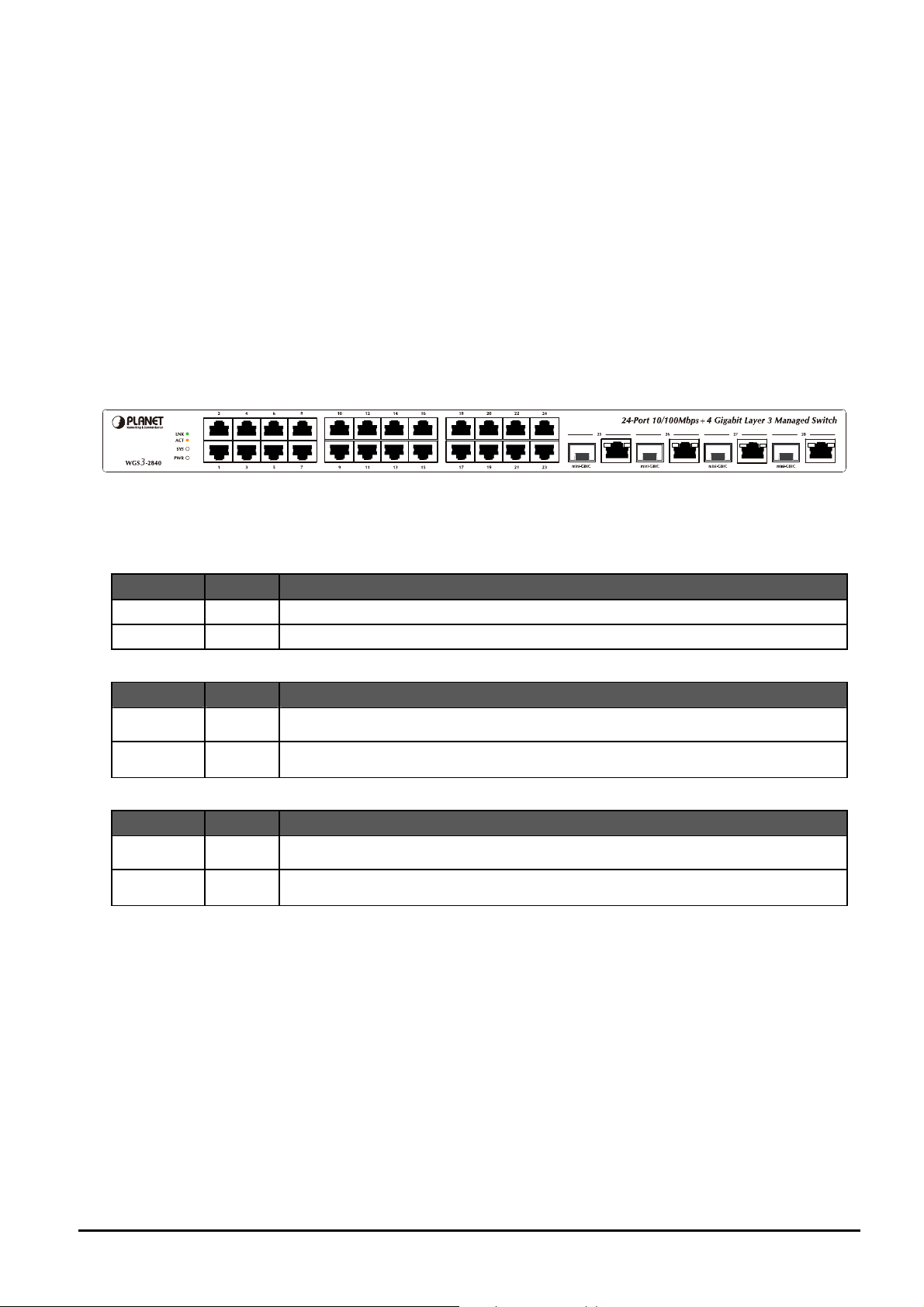
2.1 Front Panel
The Front Panel of the Layer 3 Managed Switch consists of 24x Auto-Sensing 10/100Mbps Ethernet RJ-45 Ports and
provides 4-Port Gigabit TP/SFP combo interfaces either can be 1000Base-T for 10/100/1000Mbps or 1000Base-SX/LX
through SFP (Small Factor Pluggable) interface.
The LED Indicators are also located on the front panel of the Layer 3 Managed Switch.
Figure 2-1: Layer 3 Managed Switch front panel
2.1.1 LED indicators
System
LED Color Function
PWR Green Lights to indicate that the Switch has power.
SYS Green Lights to indicate that Switch is operating.
Per 10/100Mbps port
LED Color Function
LNK Green
ACT Orange Blink to indicate that the switch port is actively sending or receiving data.
Per 10/100/1000Base-T port /SFP combo interfaces
LED Color Function
LNK Green
ACT Orange Lights to indicate that the switch port is actively sending or receiving data.
Lights to indicate the link through that port is successfully established.
Lights to indicate the link through that port is successfully established.
- 9 -
Page 10

2.2 Rear Panel
The rear panel of the Layer 3 Managed Switch indicates an AC inlet power socket, which accepts input power from 100 to
240VAC, 50-60Hz.
Figure 2-2: Layer 3 Managed Switch rear panel
Power Notice:
1. The device is a power-required device, it means, it will not work till it is powered. If your networks should active all the
time, please consider using UPS (Uninterrupted Power Supply) for your device. It will prevent you from network data
loss or network downtime.
2. In some area, installing a surge suppression device may also help to protect your Layer 3 Managed Switch from being
damaged by unregulated surge or current to the Layer 3 Managed Switch.
2.3 Hardware Installation
This part describes how to install your Layer 3 Managed Switch and make connections to the Switch. Please read the
following topics and perform the procedures in the order being presented. To install your Layer 3 Managed Switch on a
desktop or shelf, simply completed the following steps.
2.3.1 Desktop Installation
To install Layer 3 Managed Switch on a desktop or shelf, simply completed the following steps:
Step 1: Attached the rubber feet to the recessed areas on the bottom of the Layer 3 Managed Switch.
Step 2: Place the Layer 3 Managed Switch on a desktop or shelf near an AC power source.
Step 3: Keep enough ventilation space between the Layer 3 Managed Switch and the surrounding objects.
#Notice:
When choosing a location, please keep in mind the environmental restrictions discussed in Chapter 1, Section 4, Specification.
Step 4: Connect your Switch to network devices.
A. Connect one end of a standard network cable to the 10/100 RJ-45 ports on the front of the Layer 3 Managed Switch.
B. Connect the other end of the cable to the network devices such as printer servers, workstations or routers…etc.
#Notice:
Connection to the Layer 3 Managed Switch requires UTP Category 5 network cabling with RJ-45 tips. For more information, please see the Cabling Specification in Appendix A.
Step 5: Supply power to the Layer 3 Managed Switch.
A. Connect one end of the power cable to the Layer 3 Managed Switch.
B. Connect the power plug of the power cable to a standard wall outlet then power on the Layer 3 Managed Switch.
When the Layer 3 Managed Switch receives power, the Power LED should remain solid Green.
- 10 -
Page 11
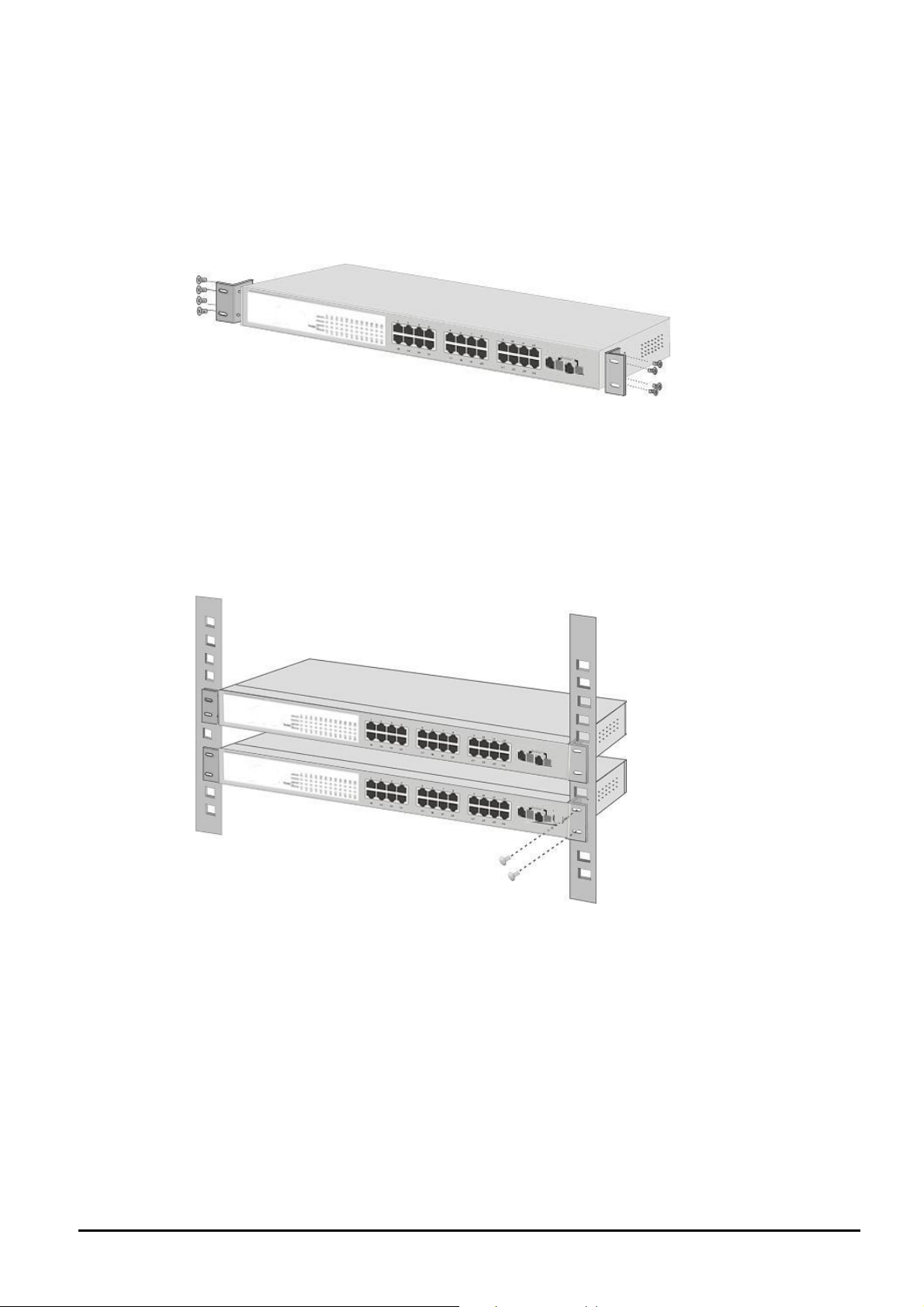
2.3.2 Rack Mounting
To install the Layer 3 Managed Switch in a 19-inch standard rack, follow the instructions described below.
Step 1: Place your Layer 3 Managed Switch on a hard flat surface, with the front panel positioned towards your front side.
Step 2: Attach a rack-mount bracket to each side of the Layer 3 Managed Switch with supplied screws attached to the
package. Figure 2-3 shows how to attach brackets to one side of the Layer 3 Managed Switch.
Figure 2-3: Attaching the brackets to the Layer 3 Managed Switch
Caution:
You must use the screws supplied with the mounting brackets. Damage caused to the parts by using incorrect screws
would invalidate your warranty.
Step 3: Secure the brackets tightly.
Step 4: Follow the same steps to attach the second bracket to the opposite side.
Step 5: After the brackets are attached to the Layer 3 Managed Switch, use suitable screws to securely attach the brackets
to the rack, as shown in Figure 2-4.
Figure 2-4: Mounting the Layer 3 Managed Switch in a Rack
Step 6: Proceed with the steps 4 and steps 5 of section 2.3.1 Desktop Installation to connect the network cabling and
supply power to your Layer 3 Managed Switch.
- 11 -
Page 12

3. SWITCH MANAGEMENT
This chapter describes how to manage the Layer 3 Managed Switch. Topics include:
- Overview
- Management methods
- Assigning an IP address to the Layer 3 Managed Switch
- Logging on to the Layer 3 Managed Switch
3.1 Overview
The Layer 3 Managed Switch provides a user-friendly, command line under console interface. Using this interface, you can
perform various Layer 3 Managed Switch configuration and management activities, including:
Command Description
First layer execute command
enable Turn on privileged mode command.
exit End current mode and down to previous mode.
help Description of the interactive help system.
show Show running system information.
terminal Set terminal line parameters.
Second layer execute command
Command Description
clear Reset functions.
configure Enter configuration mode.
copy Copy from one file to another.
debug Debugging functions (see also 'undebug').
disable Turn off privileged mode command.
enable Turn on privileged mode command.
exit End current mode and down to previous mode.
help Description of the interactive help system.
no Negate a command or set its defaults.
show Show running system information.
system Set system configuration.
terminal Set terminal line parameters.
undebug Disable debugging functions (see also 'debug').
write Write running configuration to memory, network, or terminal.
Configure commands
Command Description
- 12 -
Page 13

access-list Config acl.
arp Set a static ARP entry.
clear clear something.
commit Commit all the ACL and QoS Config to be valid.
debug Debugging functions (see also 'undebug').
enable Modify enable password parameters.
exit End current mode and down to previous mode.
help Description of the interactive help system.
hostname Set system's network name.
interface Select an interface to configure.
ip Global IP configuration subcommands.
key Authentication key management.
line Configure a terminal line.
mac-address-table Configure the MAC address table.
maximum-paths Set multipath numbers installed to FIB.
mls Global Multi-Layer Switching parameters.
monitor Configure SPAN monitoring.
move Move a access-list entry.
no Negate a command or set its defaults.
password Assign the terminal connection password.
policy-map Policy map command.
router Enable a routing process.
router-id Router identifier for this syste.
snmp-server Modify SNMP engine parameters.
spanning-tree config the spanning tree.
vlan 802.1q VLAN status.
- 13 -
Page 14

3.2 Management Methods
There are four ways to manage the Layer 3 Managed Switch:
- Local Console Management via the serial port of Layer 3 Managed Switch.
- Remote Console Management via a network or dial-up connection.
- Web Management via a network or dial-up connection.
-Using SNMP Network Management Station.
3.2.1 Local Console Management
You can manage the Layer 3 Managed Switch locally by connecting a VT100 terminal, or a personal computer or workstation with terminal emulation software, to the serial port of Layer 3 Managed Switch. The terminal or w orkstation connects
to the serial port of Layer 3 Managed Switch, using a null modem cable that has the appropriate connectors on each end.
This management method is ideal when:
- The network is unreliable.
- The Network Manager does not have direct network connection.
The serial port of Layer 3 Managed Switch, default setting is set to 9600 baud using a character format of 8 data bits, no
parity, and 1 stop bit.
Therefore, configure the terminal or workstation to use these settings before you log on to the Layer 3 Managed Switch.
You can change this default setting, if desired, after you log on.
3.2.2 Remote Console Management
You can manage the Layer 3 Managed Switch remotely by having a remote host establish a Telnet connection to
Layer 3 Managed Switch via an Ethernet or modem link.
the
Using this management method:
The
Layer 3 Managed Switch must have an Internet Protocol (IP) address.
The Remote Console Management interface is identical in appearance and functionality to the Local Console
Management interface described in the previous section.
3.2.3 Web Management
You can manage the Layer 3 Managed Switch remotely by having a remote host with web browser, such as
Microsoft Internet Explorer or Netscape Navigator.
Using this management method:
The
Layer 3 Managed Switch must have an Internet Protocol (IP) address accessible for the remote host.
3.2.4 SNMP Management
You can manage the Layer 3 Managed Switch across a LAN using an SNMP Network Management Station with
a graphical user interface.
This management method lets you monitor statistical counters and set switch parameters from the remote
Network Management Station.
Using this management method:
- The network must run the IP protocol.
- The
Layer 3 Managed Switch must have an IP address.
- 14 -
Page 15
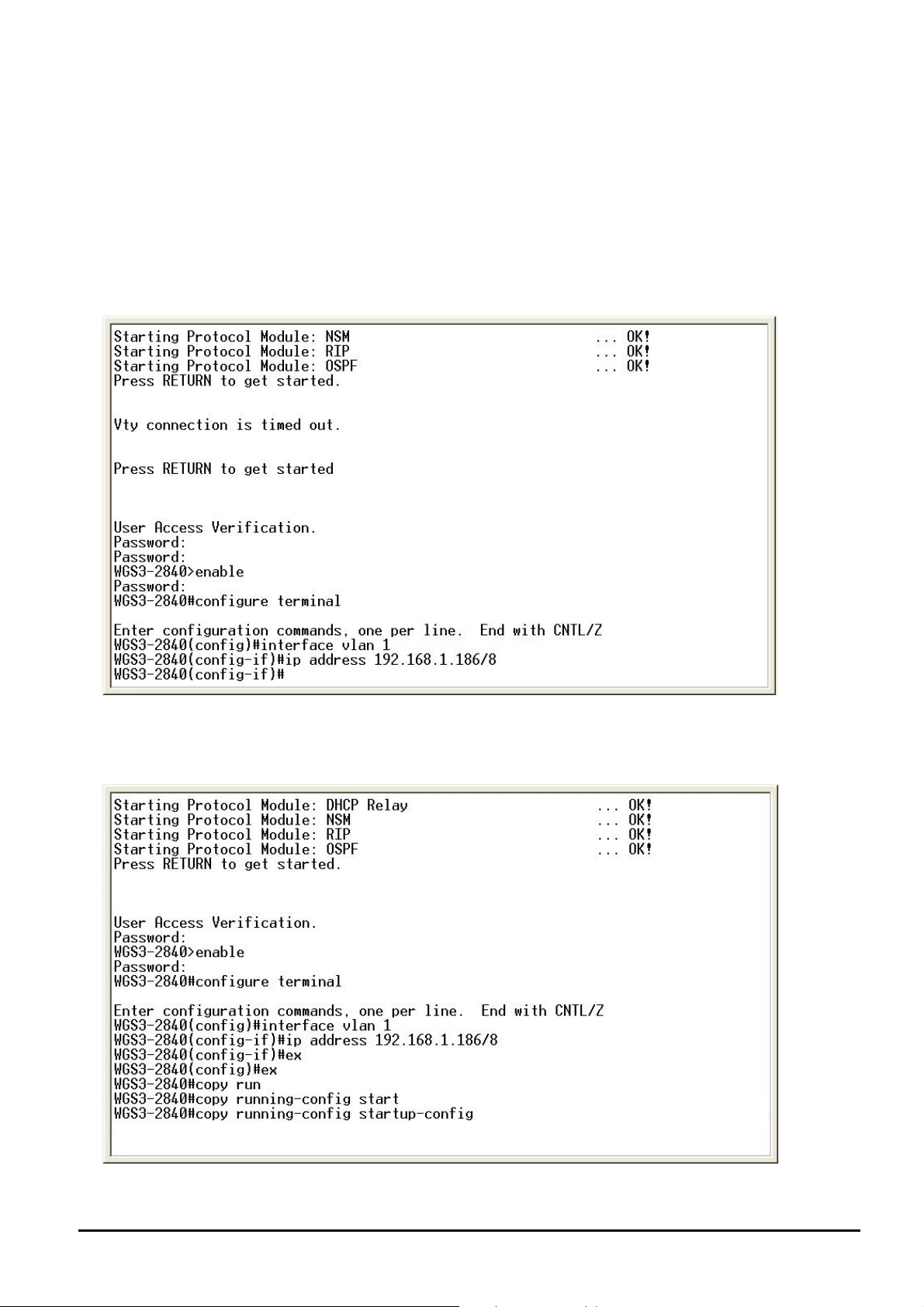
3.3 Assigning an IP Address to the Layer 3 Managed Switch
To manage the Layer 3 Managed Switch remotely through the console port or with an SNMP Management Station, you
must assign an IP address to the Layer 3 Managed Switch.
The default IP address of the Layer 3 Managed Switch is “192.168.1.254”. If you want to change the IP address, for
example, change the IP address to “192.168.1.186” please input the following command:
WGS3-2840# configuration terminal
(config)# interface vlan 1
(confif-if)#ip address 192.168.1.186/8
Now the IP address has changed to 192.168.1.186. The changed IP address will remain the original after reboot unless
save the configuration. To do this, please input “exit” or “ex” command twice for return to previous configuration level and
input “WGS3-2840# copy running-config startup-config” command to save the current configuration.
You can access the Web interface of Layer 3 Managed Switch through the new IP address.
- 15 -
Page 16
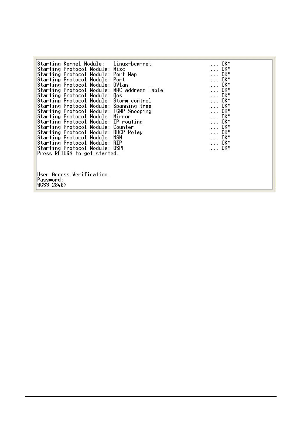
3.4 Logging on to the Layer 3 Managed Switch
When you log on to the Layer 3 Managed Switch console port for the first time, the following message asks the login access
password.
The factory default login password is admin.
#Notice:
1. For security reason, please change and memorize the new password after this first setup.
2. Only accept command in lowercase letter under console interface.
- 16 -
Page 17
4. WEB MANAGEMENT
Before login the Web interface of Layer 3 Managed Switch, please setup the “IP Address” with local serial console port
(RS232 port) and use this IP address to configure Layer 3 Managed Switch through the Web interface.
Or modify your PC’s IP domain to the same with Layer 3 Managed Sw itch then use the default IP address (192.168.0.100)
to remote configure Layer 3 Managed Switch through the Web interface.
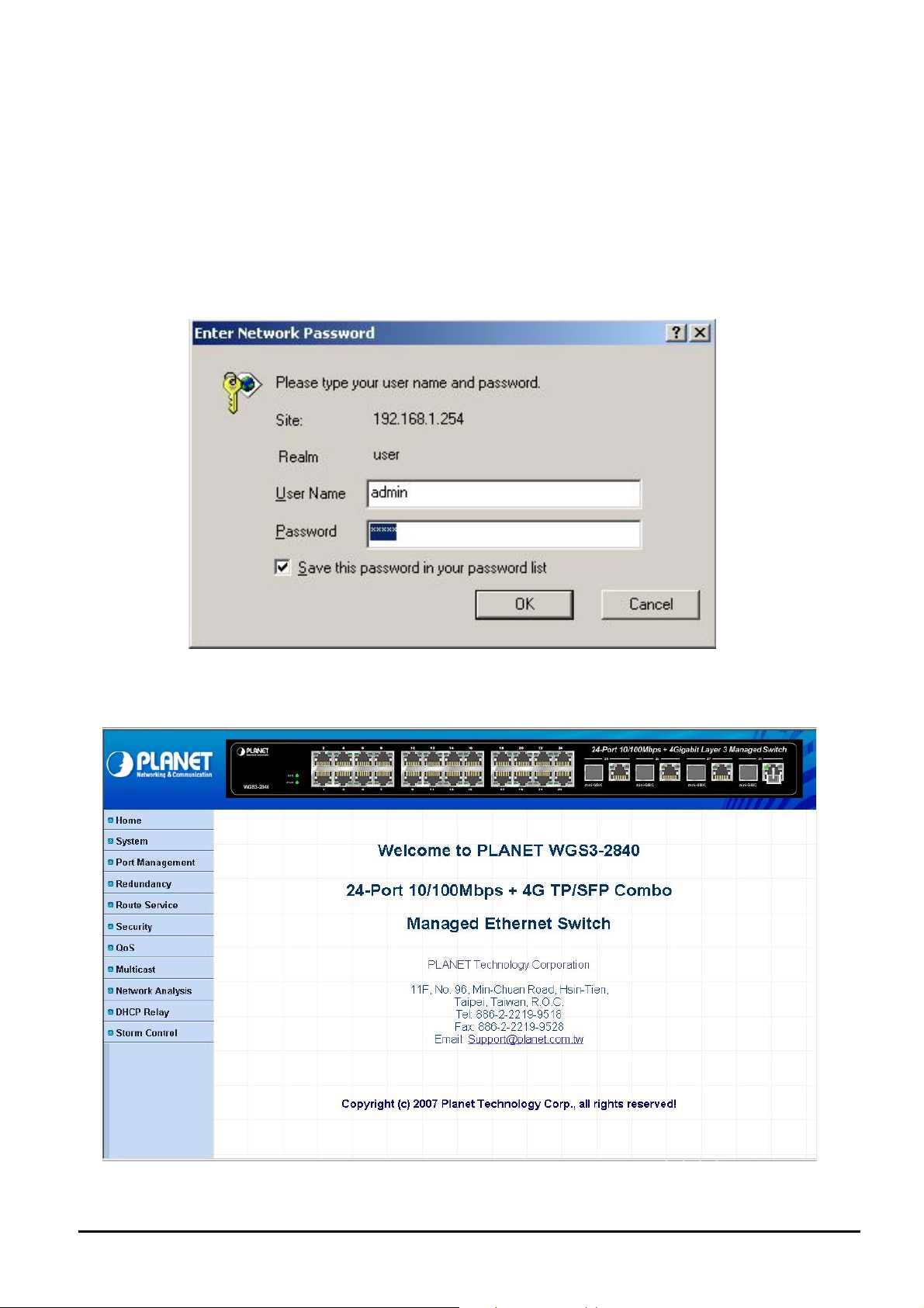
4.1 Login in to the Layer 3 Managed Switch
To access the Web-browser interface you must first enter the user name and password, the default user name and
password is "admin". You will see the following screen comes out on the Web browser program:
Figure 4-1 The Web login Page screen of Layer 3 Managed Switch
After the User name and Password is entered, you will see the web main menu screen.
Figure 4-2 The web main menu screen of Layer 3 Managed Switch
- 17 -
Page 18
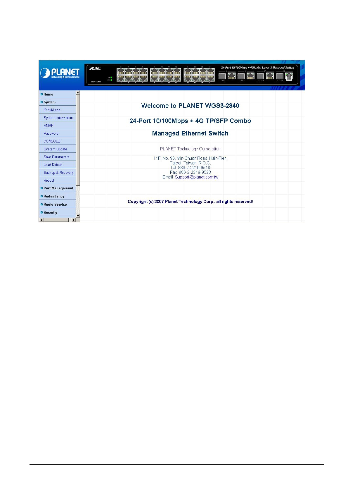
4.2 System
This section provides system information from Layer 3 Managed Switch, the screen in Figure 4-3 appears.
Figure 4-3 System Web Page screen
The system item include following functions:
IP Address: please refer to section 4.2.1.
System information: please refer to section 4.2.2.
SNMP: please refer to section 4.2.3.
Password: please refer to section 4.2.4.
Console: please refer to section 4.2.5.
System Update: please refer to section 4.2.6.
Save Parameters: please refer to section 4.2.7.
Load Default: please refer to section 4.2.8.
Backup & Recovery: please refer to section 4.2.9.
Reboot: please refer to section 4.2.10.
- 18 -
Page 19
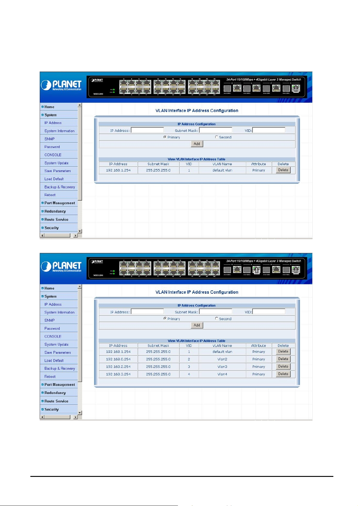
4.2.1 IP Address
This section allows modify the IP address, Subnet Mask, Gateway and VID (VLAN ID) of Layer 3 Managed Switch; also
allow assign multi-IP subnet address for Layer 3 VLAN routing. The screen in Figure 4-4 & 4-5 appears.
Figure 4-4 IP Address Web Page screen
Figure 4-5 IP Address Web Page screen
- 19 -
Page 20
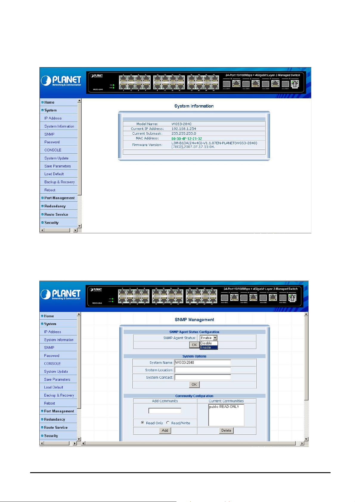
4.2.2 System Information
This section provides system information of Layer 3 Managed Switch, such as Model name, current IP Address, current
Subnet mask, MAC Address and Firmware version. The screen in Figure 4-6 appears.
Figure 4-6 System Information Web Page screen
4.2.3 SNMP
This section allows to management the Layer 3 Managed Switch through the Simple Network Management Protocol
(SNMP). It provides protocol that governs the transfer of information between management stations (PC with SNMP
software) and agent (Layer 3 Managed Switch). The screen in Figure 4-7 appears.
Figure 4-7 SNMP Web Page screen
- 20 -
Page 21
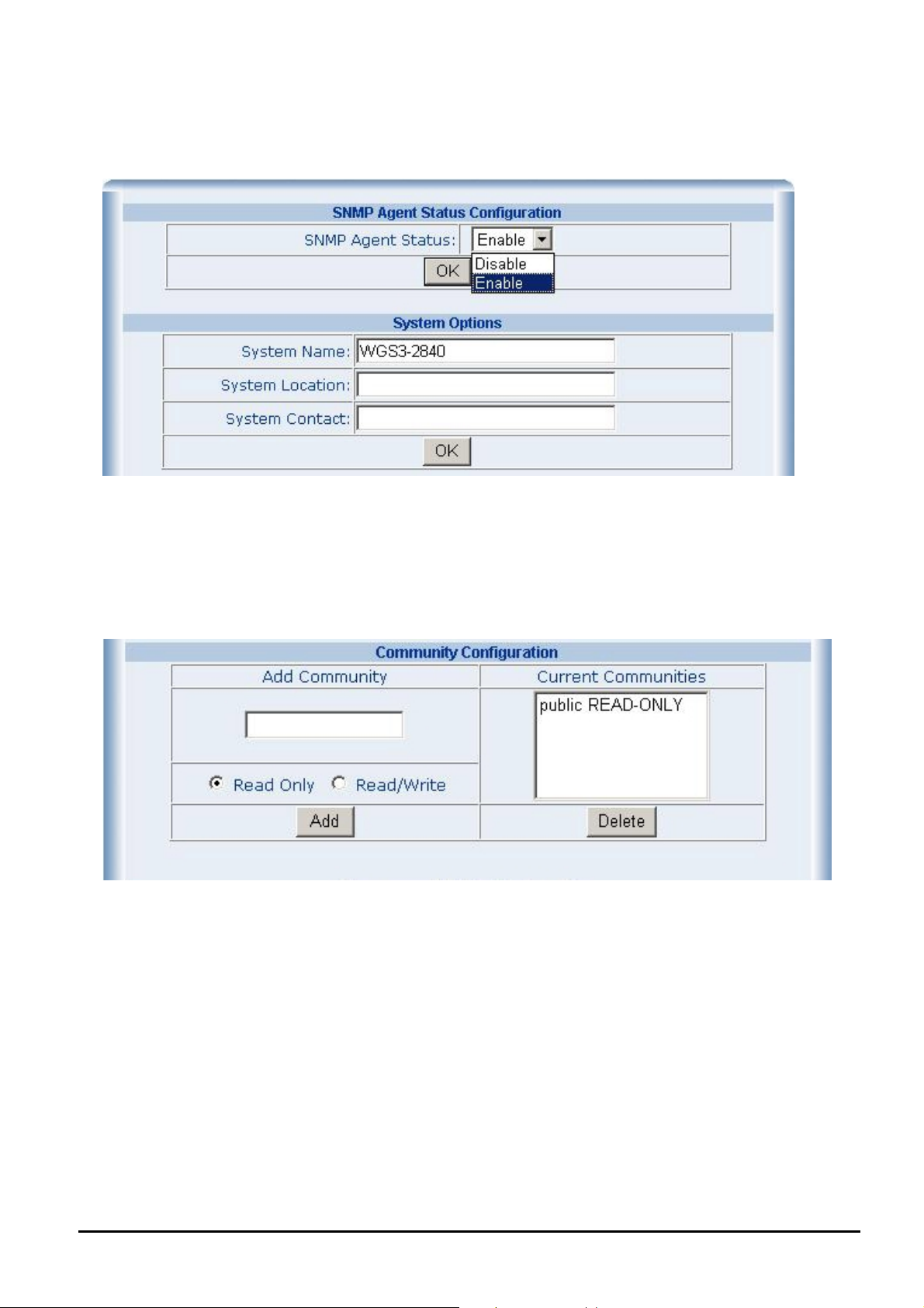
Use this Web page to disable or enable the SNMP function of Layer 3 Managed Switch, and define the management stations as trap managers and key in SNMP community strings. It also allows user to define a System name, System location
and System contact person for the Layer 3 Managed Switch. Fill in the system options data and click “OK” button to update
the change of this page. The screen in Figure 4-8 appears.
Figure 4-8 System Options Web Page screen
Please check the detail description of parameters as below:
System Name: enter the system name for this Layer 3 Managed Switch.
System Location: enter the location of this Layer 3 Managed Switch.
System Contact: enter the name of system administrator. Then click “OK” to take effect.
Community configuration serves as password and can be entered as following screen:
Figure 4-9 Community Configuration Web Page screen
Please check the detail description of parameters as below:
Read Only: enables requests accompanied by this string to display MIB-object information.
Read Write: enables requests accompanied by this string to display MIB-object information and set MIB objects.
After input all necessary information, please click “Add” button to take affect, also can click “Delete” button to delete
existence community.
- 21 -
Page 22
Management Station
A Trap manager is a management station that receives traps, the system alerts generated by the Layer 3 Managed Switch.
If Trap manager is not defined then there is no trap issued. Create a Trap management station by enter the IP address of
the station and trap community name. The screen in Figure 4-10 appears.
Figure 4-10 Management Station Web Page screen
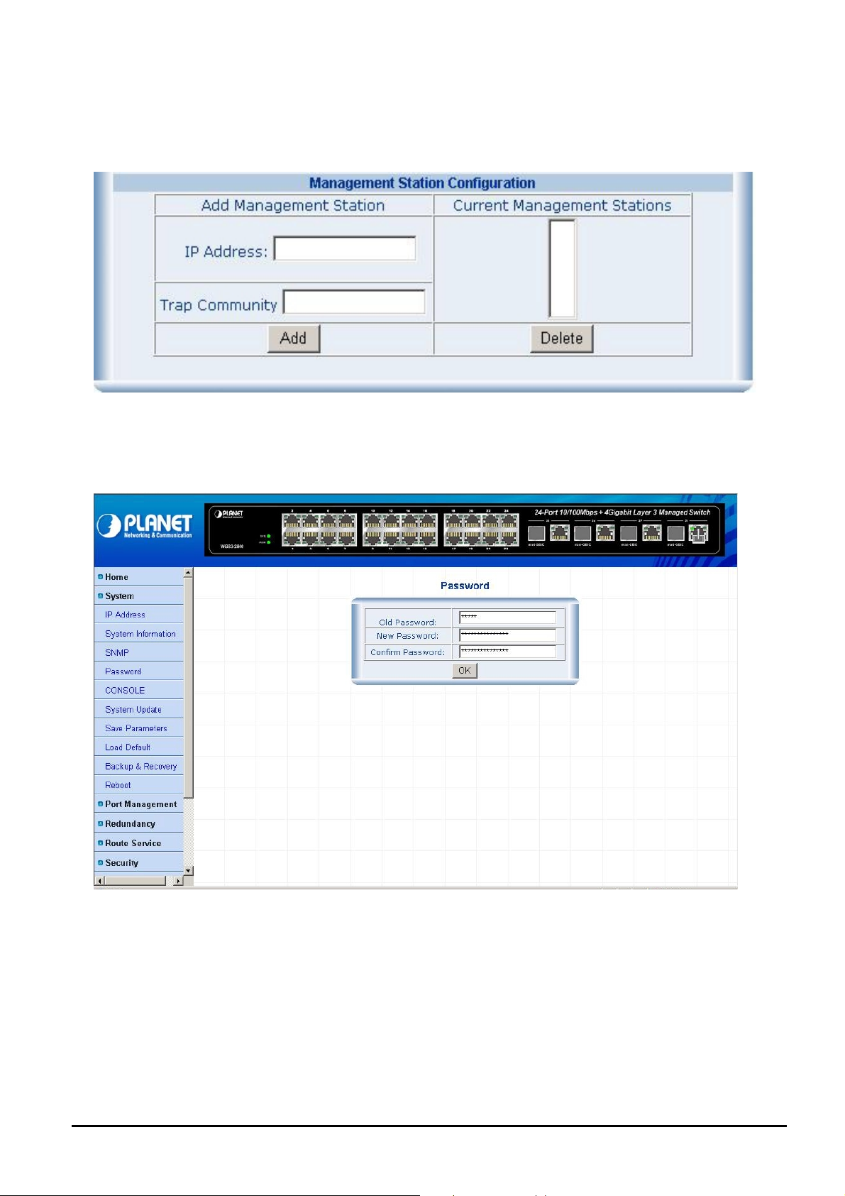
4.2.4 Password
This section allows modify the password of Layer 3 Managed Switch. The screen in Figure 4-11 appears.
Figure 4-11 Password Web Page screen
Password modifies procedure:
1. Input the current password in “Old Password” space.
2. Input the new password in “New Password” space.
3. Input the new password again in “Confirm Password” space
4. Click the “OK” button to complete the password modify procedure.
#Notice: Up to 15 characters is allowed for the User password.
- 22 -
Page 23
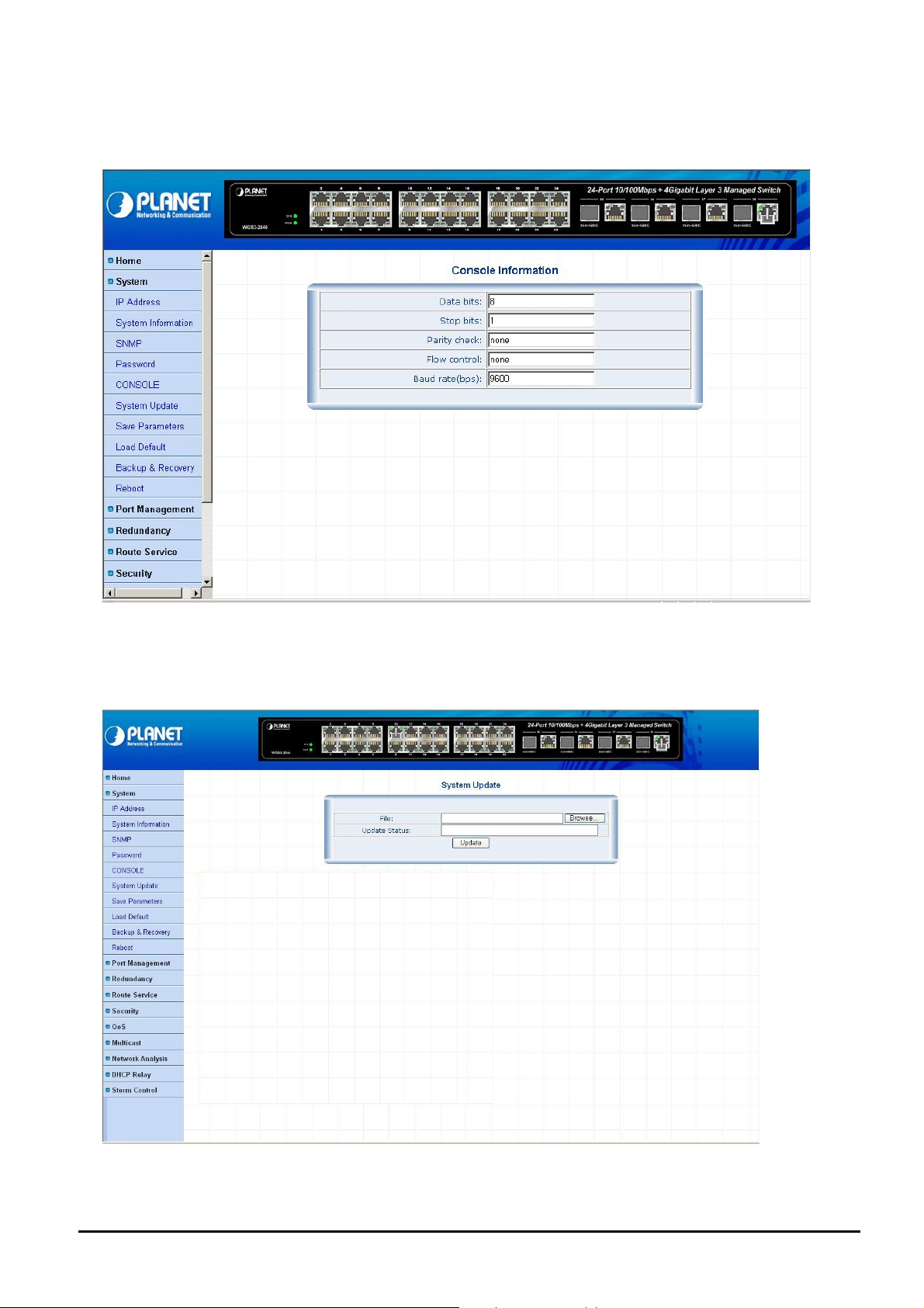
4.2.5 Console
This section provides read-only Console information of Layer 3 Managed Switch. The screen in Figure 4-12 appears.
Figure 4-12 Console Information Web Page screen
4.2.6 System Update
This section provides firmware upgrade function of Layer 3 Managed Switch. The screen in Figure 4-13 appears.
Figure 4-13 System Update Web Page screen
- 23 -
Page 24

Firmware Upgrade procedu re:
1. Login to the Web management interface of Layer 3 Managed Switch.
2. Click on the "System" menu link on the left hand sid of the Web page.
3. Click on the "System Update" sub-menu of the "System".
4. In the "System Update" function main screen, click on the "Browse" button.
5. The computer screen then popup the file selection application.
6. Figure out the new firmware in your workstation.
Figure 4-14 System Update Web Page screen
7. Click on the Update button in the management interface, the windows popup screen will appears.
- 24 -
Page 25

Figure 4-15 System Update Web Page screen
8. Please wait until the Layer 3 Managed Switch reboot.
Figure 4-16 System Update Web Page screen
9. After the Layer 3 Managed Switch reboot complete and you can start to use the latest firmware.
#Notice: please do not power off the Layer 3 Managed Switch during the firmware upgrade process.
- 25 -
Page 26

4.2.7 Save Parameters
This section allows save current setting of Layer 3 Managed Switch. The screen in Figure 4-17 appears.
Figure 4-17 Save Parameters Web Page screen
4.2.8 Load Default
This section allows reset the Layer 3 Managed Switch to factory default mode, after execute this function. Please reboot
the Layer 3 Managed Switch for take affect and the screen in Figure 4-18 appears.
Figure 4-18 Load Default Web Page screen
- 26 -
Page 27

4.2.9 Backup & Recovery
This section allows backup and recovery the system parameters of Layer 3 Managed Switch. The screen in Figure 4-19
appears.
Figure 4-19 Backup & Recovery Web Page screen
Backup the system parameters procedure:
1. Choose “Backup the System parameters” function from Web page of Layer 3 Managed Switch.
2. Then the File Download popup screen appears and asks you “Do you want to save this file”? Clink “Save”
button to download and save this system parameters file (parm_back.bin) into your PC.
Figure 4-20 Backup the System parameters Web Page screen
- 27 -
Page 28

Figure 4-21 Backup the System parameters Web Page screen
Parameters Recovery procedure:
1. Use “parameters Recovery” function from Web page of Layer 3 Managed Switch.
2. Click “Browse” button to locate the system parameters file (parm_back.bin) from your PC.
Figure 4-22 Parameters Recovery Web Page screen
- 28 -
Page 29

Figure 4-23 Parameters Recovery Web Page screen
3.
Clink “OK” button to start the Parameters Recovery process of Layer 3 Managed Switch.
Figure 4-24 Parameters Recovery Web Page screen
- 29 -
Page 30

When complete the Parameters Recovery process of Layer 3 Managed Switch, the following screen appears.
Figure 4-25 Parameters Recovery Web Page screen
4.2.10 Reboot
This section allows reboot the Layer 3 Managed Switch, the screen in Figure 4-26 appears.
Figure 4-26 Reboot Web Page screen
- 30 -
Page 31

4.3 Port Management
This section provides port configuration, port statistics and Band Restricting functions from Layer 3 Managed Switch. The
port Management screen in Figure 4-27 appears.
Figure 4-27 Port Management Web Page screen
The system item include following functions:
Port Configuration: please refer to section 4.3.1.
Port Statistics: please refer to section 4.3.2.
Band Restricting: please refer to section 4.3.3.
- 31 -
Page 32

4.3.1 Port Configuration
This section provides port configuration function from Layer 3 Managed Switch. The port configuration screen in Figure
4-28 appears. Table 4-1 & 4-2
descriptions the port configuration Web page objects.
Figure 4-28 Port Configuration Web Page screen
Object Description
Interface
Management Status
Speed / Duplex
Flow control
OK
Table 4-1 Descriptions of the Port Configuration Web Page screen Objects
Object Description
Interface
Management Status
Link Status
Speed (Config / Actual)
Duplex(Config / Actual)
Flow control (Config / Ac-
tual)
Refresh
Select the Fast Ethernet port or Gigabit Ethernet port for further management.
Allow disable or enable one specific Fast Ethernet port or Gigabit Ethernet port.
Allow set one specific Fast Ethernet port or Gigabit Ethernet port speed duplex mode,
the available options shown as below:
Fast Ethernet: Auto, 10H, 10F, 100H, 100F.
Gigabit Ethernet: Auto, 10H, 10F, 100H, 100F, 1000F.
Allow disable (OFF) or enable (ON) flow control in full-duplex mode.
Clink this button for take effect.
Display all the ports of Layer 3 Managed Switch.
Display current management status from each port of Layer 3 Managed Switch.
Display current link status from each port of Layer 3 Managed Switch.
Display the current speed mode and configuration speed mode from each port.
Display the current duplex mode and configuration duplex mode from each port.
Display the current flow control mode and configuration flow control mode from each
port.
To refresh the port status table.
Table 4-2 Descriptions of the View Port Status Web Page screen Objects
- 32 -
Page 33

4.3.2 Port Statistics
This section provides port statistics function from Layer 3 Managed Switch. The port statistics screen in Figure 4-29 appears. Table 4-3
description the port statistics Web page objects.
Figure 4-29 Port Statistics Web Page screen
Object Description
Port
Management Status
Link Status
RX Bytes
RX Pkts
TX Bytes
TX Pkts
Collision Pkts
Discard Pkts
Refresh
Reset
Table 4-3 Descriptions of the Port Statistics Web Page screen Objects
Display all the ports of Layer 3 Managed Switch.
Display current management status from each port of Layer 3 Managed Switch.
Display current link status from each port of Layer 3 Managed Switch.
Display detail receives traffic with Bytes unit from each port of Layer 3 Managed Switch.
Display detail receives traffic with Packet unit from each port of Layer 3 Managed Switch.
Display detail transmits traffic with Bytes unit from each port of Layer 3 Managed Switch.
Display detail transmits traffic with Packet unit from each port of Layer 3 Managed Switch.
Display collision packet receives from each port of Layer 3 Managed Switch.
Display discard packet receives from each port of Layer 3 Managed Switch.
To refresh the port statistics table.
To clear all the traffic counter from the port statistics table.
- 33 -
Page 34

4.3.3 Band Restricting
This section provides band restricting function from Layer 3 Managed Switch. The band restricting screen in Figure 4-30
appears. Table 4-4
description the band restricting Web page objects.
Figure 4-30 Band Restricting Web Page screen
Object Description
Ingress Port List
Egress Port List
Band(64~100000Kbps)
OK
Table 4-4 Descriptions of the Band Restricting Web Page screen Objects
Select specific Fast Ethernet port or Gigabit Ethernet port for further management.
Select specific Fast Ethernet port or Gigabit Ethernet port for further management.
Assign bandwidth value on specific Fast Ethernet port or Gigabit Ethernet port.
Clink this button for take effect.
- 34 -
Page 35

4.4 Redundancy
This section provides Rapid Spanning Tree and Link Aggregation function from Layer 3 Managed Switch. The Redundancy
screen in Figure 4-31 appears.
Figure 4-31 Redundancy Web Page screen
The system item include following functions:
Rapid Spanning Tree: please refer to section 4.4.1.
Link Aggregation: please refer to section 4.4.2.
- 35 -
Page 36

4.4.1 Rapid Spanning Tree
This section provides Rapid Spanning Tree function from Layer 3 Managed Switch. The Spanning Tree Protocol (STP) is
a standardized method (IEEE 802.1d) for avoiding loops in Ethernet networks. And, the Rapid Spanning Tree Protocol
(IEEE 802.1w RSTP) is an evolution of the Spanning Tree Protocol and provides for faster spanning tree convergence
after a topology change. When enable STP/RSTP function, please ensure only one path at a time is active between any
two nodes on the network. We can enable STP/RSTP from the Switch setting advanced item of web interface. We are
recommended you to enable STP/RSTP on whole Switches for ensures a single active path in the network.
Figure 4-32 Rapid Spanning Tree Bridge Configuration Web Page screen
Rapid Spanning Tree Bridge Configuration:
This function provides Rapid Spanning Tree Bridge Configuration and view the Spanning tree Root Bridge information. The
Rapid Spanning Tree screen in Figure 4-32 appears. Table 4-5
ration Web page
Object Description
Spanning Tree
Status
Force Protocol
Version
Max Age (6-40s)
Hello Time (1-10s)
Forward Delay
Time (4-30s)
Bridge Priority
(0-61440)
Table 4-5 Descriptions of Rapid Spanning Tree Bridge Configuration Web Page screen Objects
After setup completed, please click “OK” button to take effect.
objects.
Allow choose Disable or enable Spanning Tree function. Default mode is Disable.
Allow choose IEEE 802.1d Spanning Tree or IEEE 802.1w Rapid Spanning Tree function.
0= IEEE 802.1d STP, 2=IEEE 802.1w RSTP. Default mode is 2.
The number of seconds a bridge waits without receiving Spanning-Tree Protocol configuration
messages before attempting a reconfiguration. Enter a value between 6 through 40.
The time that controls switch sends out the BPDU packet to check STP current status. Enter a
value between 1 through 10.
The number of seconds a port waits before changing from its Spanning-Tree Protocol learning
and listening states to the forwarding state. Enter a value between 4 through 30.
A value used to identify the root bridge. The bridge with the lowest value has the highest priority
and is selected as the root. If change the value, must reboot the switch assign path priority
number. The value must be multiple of 4096 according to the protocol standard rule.
descriptions the Rapid Spanning Tree Bridge Configu-
#
Notice: please follow the rule to configure the MAX Age, Hello Time, and Forward Delay Time.
2 x (Forward Delay Time value –1) > = Max Age value >= 2 x (Hello Time value +1)
- 36 -
Page 37

RSTP Port Configuration
This function provides Rapid Spanning Tree Bridge Configuration and view the Spanning tree Root Bridge information. The
Rapid Spanning Tree screen in Figure 4-33 appears. Table 4-6
ration Web page objects.
Figure 4-33 RSTP Port Configuration Web Page screen
Object Description
descriptions the Rapid Spanning Tree Bridge Configu-
Interface
Edge Port
P2P Status
Path Cost
Port Priority
Port Mcheck Set
Fa 0/ , Gi 0/, Po
OK
Table 4-6 Descriptions of RSTP Port Configuration Web Page screen Objects
Select one specific Fast Ethernet port or Gigabit Ethernet port for further management.
The port directly connected to end stations cannot create bridging loop in the network. To con-
figure the port as an edge port, set the port to “True” status.
Some of the rapid state transactions that are possible within RSTP are dependent upon whether
the port concerned can only be connected to exactly one other bridge (i.e. it is served by a
point-to-point LAN segment), or can be connected to two or more bridges (i.e. it is served by a
shared medium LAN segment). This function allows the P2P status of the link to be manipulated
administratively. True is P2P enabling. False is P2P disabling.
The cost of the path to the other bridge from this transmitting bridge at the specified port. Enter a
number 1 through 200000000.
Decide which port should be blocked by priority in LAN. Enter a number 0 through 240. The value
of priority must be the multiple of 16.
Select the Fast Ethernet port or Gigabit Ethernet port for further management.
Clink this button for take effect.
After setup completed, please click “OK” button to take effect.
- 37 -
Page 38

4.4.2 Link Aggregation
This section provides Link Aggregation function from Layer 3 Managed Switch. The Link Aggregation screen in Figure 4-34
appears. Table 4-7 descriptions the Rapid Spanning Tree Bridge Configuration Web page objects.
Figure 4-34 Link Aggregation Configuration Web Page screen
Object Description
Port
Aggregation Group
Member Ports
ADD
DELETE
Table 4-7 Descriptions of Link Aggregation Web Page screen Objects
#
Notice: supports 12 Link Aggregation groups with 8 member ports can be allowing on per link
aggregation group.
Display all the Fast Ethernet ports and Gigabit Ethernet ports from port 1 to port 28.
Display all the link aggregation groups from 1 to 12.
Display the member ports from each link aggregation groups from 1 to 12.
Click this button to add specific port to link aggregation groups.
Click this button to remove specific port from link aggregation groups.
- 38 -
Page 39

4.5 Route Service
This section provides Static Route, RIP and OSPF function of Layer 3 Managed Switch. The Route Service screen in
Figure 4-35 appears.
Figure 4-35 Route Service Web Page screen
The system item include following functions:
Static Route: please refer to section 4.5.1.
RIP: please refer to section 4.5.2.
OSPF: please refer to section 4.5.3.
- 39 -
Page 40

4.5.1 Static Route
This section provides Static Route function from Layer 3 Managed Switch. Static route provide manually intensive to keep
up for very quick and effective way to route data from one subnet to different subnet. The static route is a hard coded path
that specifies how the router will get to a certain subnet by using a certain path.
appears and Table 4-8
descriptions the Static Route Configuration Web page objects.
The Static Route screen in Figure 4-36
Figure 4-36 Static Route Configuration Web Page screen
Object Description
Target Network Address/Host
Subnet Mask
Next Hop
Metric (1-255)
ADD
DELETE
Table 4-8 Descriptions of Static Route Web Page screen Objects
Allow input the IP address of Target Network or Host.
Allow input the subnet mask value.
Allow input the value of Next Hop, indicates the IP address of the next hop to which
packets for the entry should be forwarded
Allow input the value of Metric and the available range is 1-255.
Click this button to add specific port to link aggregation groups.
Click this button to remove specific port from link aggregation groups.
.
- 40 -
Page 41

4.5.2 RIP
This section provides RIP function from Layer 3 Managed Switch. The Routing Information Protocol (RIP), it is one of the
most enduring of all routing protocols. RIP is also one of the more easily confused protocols because a variety of RIP-like
routing protocols proliferated, some of which even used the same name! RIP and the myriad RIP-like protocols were based
on the same set of algorithms that use distance vectors to mathematically compare routes to identify the best path to any
given destination address. These algorithms emerged from academic research that dates back to 1957.
Today's open standard version of RIP, sometimes referred to as IP RIP, is formally defined in two documents: Request for
Comments (RFC) 1058 and Internet Standard (STD) 56. As IP-based networks became both more numerous and greater
in size, it became apparent to the Internet Engineering Task Force (IETF) that RIP needed to be updated. Consequently,
the IETF released RFC 1388 in January 1993, which was then superseded in November 1994 by RFC 1723, which describes RIP 2 (the second version of RIP). These RFCs described an extension of Rip’s capabilities but did not attempt to
obsolete the previous version of RIP. RIP 2 enabled RIP messages to carry more information, which permitted the use of a
simple authentication mechanism to secure table updates. More importantly, RIP 2 supported subnet masks, a critical
feature that was not available in RIP. The RIP screen in Figure 4-37 appears and Table 4-9 descriptions the RIP Configuration Web page objects.
Figure 4-37 RIP Configuration Web Page screen
Object Description
IP Address Allow input the IP address for the entry.
Subnet Mask Allow input the subnet mask value for the entry. If this field is zero, no subnet mask has been
specified for the entry.
Send Version Allow to define the RIP version used on transmit mode, the available options are RIPV1 and
RIPV2. Default mode is RIPV1.
Receive Version Allow to define the RIP version used on receive mode, the available options are RIPV1 and RIPV2.
Default mode is RIPV1.
Authentication Allow to define the authentication mode with NONE, TEXT and MD5. Default mode is NONE.
KID (0-255) Allow input the KID value and available range is 0-255.
Password Allow input the password and supports up to 16 characters.
Horizon Split Allow define the Horizon Split and the available options are DISABLE, SIMPLE and POISON
REVERSE. Default mode is POISON REVERSE.
OK Click this button to take affect.
Table 4-9 Descriptions of RIP Web Page screen Objects
- 41 -
Page 42

4.5.3 OSPF
This section provides OSPF function from Layer 3 Managed Switch. OSPF (Open Shortest Path First) is a router protocol
used within larger autonomous system
protocol that is installed in many of today's corporate networks. Like RIP, OSPF is designated by the Internet Engineering
Task Force (IETF
) as one of several Interior Gateway Protocols (IGPs).
networks in preference to the Routing Information Protocol (RIP), an older routing
Using OSPF, a host that obtains a change to a routing table or detects a change in the network immediately multicast
information to all other host
the entire routing table is sent, the host using OSPF sends only the part that has changed. With RIP, the routing table is
sent to a neighbor host every 30 seconds. OSPF multicasts the updated information only when a change has taken place.
Rather than simply counting the number of hop
additional network information. OSPF also lets the user assign cost metric
given preference. OSPF supports a variable network subnet
within OSPF for router-to-end station communication. Since many networks using RIP are already in use, router manufacturers tend to include RIP support within a router designed primarily for OSPF. The OSPF screen in Figure 4-38 appears
and Table 4-10 descriptions the OSPF Configuration Web page objects.
s in the network so that all will have the same routing table information. Unlike the RIP in w hich
s, OSPF bases its path descriptions on "link states" that take into account
s to a given host router so that some paths are
mask so that a network can be subdivided. RIP is supported
s the
Figure 4-38 OSPF Configuration Web Page screen
Object Description
Router-ID Allow input the Router ID.
IP Address Allow input the IP address for the entry.
Subnet Mask Allow input the subnet mask value for the entry. If this field is zero, no subnet mask has been
specified for the entry.
Area (0-4294967295) Allow input the Area value and available range is 0-4294967295.
OK Click this button to take affect.
Table 4-10 Descriptions of OSPF Web Page screen Objects
- 42 -
Page 43

4.6 Security
This section provides ACL, VLAN, ARP, Static MAC Address, MAC Address Filter, MAC Address Learning and MAC Aging
time function of Layer 3 Managed Switch. The security screen in Figure 4-39 appears.
Figure 4-39 Security Web Page screen
The system item include following functions:
ACL: please refer to section 4.6.1.
VLAN: please refer to section 4.6.2.
ARP: please refer to section 4.6.3.
Static MAC Address: please refer to section 4.6.4.
MAC Address Filter: please refer to section 4.6.5.
MAC Address Learning: please refer to section 4.6.6.
MAC Aging Time: please refer to section 4.6.7.
- 43 -
Page 44

4.6.1 ACL
This section provides ACL function from Layer 3 Managed Switch; this function provides ACL Configuration and view the
ACL table information. The ACL screen in Figure 4-40 appears.
Figure 4-40 ACL Configuration Web Page screen
The ACL function provide five different ACL type for further management, the detail descriptions are shown as below.
Standard IP ACL
This section provides Standard IP ACL function from Layer 3 Managed Switch; this function provides Standard IP ACL
Configuration and view the ACL table information. The Standard IP ACL screen in Figure 4-40 appears and Table 4-11
descriptions the Standard IP ACL Configuration Web page objects.
Object Description
ACL Type:
PERMIT/ DENY
Source IP Address:
Wildcard:
Counter:
DSCP ( 0-63):
Capture
Policer: Average(1-1024Mbps)
Burst (0-512Kbps)
Add
Reset
Allow choose different ACL type that shown as below:
Standard IP ACL, Extended IP ACL, Protocol type-code, Standard MAC ACL
Extended MAC ACL
Allow choose permit or deny for different ACL type.
Allow input the source IP address.
Allow input the value of wildcard for source IP address.
Allow define the value for the counter function.
Allow input the value of DSCP and the available range is 0-63.
Allow to choose disable (OFF) or enable (ON) the capture function.
Allow to defined the value of Average and the available range is 1-1024Mbps.
Allow to defined the value of Burst and the available range is 0-512Kbps.
Click this button to add specific ACL setting to ACL table.
Click this button to remove specific ACL setting from ACL table.
Table 4-11 Descriptions of Standard IP ACL Web Page screen Objects
- 44 -
Page 45

Extended IP ACL
This section provides Extended IP ACL function from Layer 3 Managed Switch; this function provides Extended IP ACL
Configuration and view the ACL table information. The Extended IP ACL screen in Figure 4-41 appears and Table 4-12
descriptions the Extended IP ACL Configuration Web page objects.
Figure 4-41 Extended IP ACL Configuration Web Page screen
Object Description
ACL Type:
PERMIT/ DENY
Source IP Address:
Wildcard:
Destination IP Address
Wildcard:
Protocol Type
Custom (0-255):
Counter:
DSCP ( 0-63):
Capture
Policer: Average(1-1024Mbps)
Burst (0-512Kbps)
Add
Reset
Allow choose different ACL type that shown as below:
Standard IP ACL, Extended IP ACL, Protocol type-code, Standard MAC ACL
Extended MAC ACL
Allow choose permit or deny for different ACL type.
Allow input the source IP address.
Allow input the value of wildcard for source IP address.
Allow input the destination IP address.
Allow input the value of wildcard for destination IP address.
Allow choose different protocol type for management, the available options are
ANY, OTHER, AHP, EIGRP, ESP,GRE, ICMP, IGMP, IGRP, IP, IPINIP, NOS,
OSPF, PCP, PIM,TCP,UDP
Allow input the value of customer and the available range is 0-255.
Allow define the value for the counter function.
Allow input the value of DSCP and the available range is 0-63.
Allow to choose disable (OFF) or enable (ON) the capture function.
Allow to defined the value of Average and the available range is 1-1024Mbps.
Allow to defined the value of Burst and the available range is 0-512Kbps.
Click this button to add specific ACL setting to ACL table.
Click this button to remove specific ACL setting from ACL table.
Table 4-12 Descriptions of Extended IP ACL Web Page screen Objects
- 45 -
Page 46

Protocol type-code
This section provides Protocol type-code function from Layer 3 Managed Switch; this function provides Protocol type-code
Configuration and view the ACL table information. The Protocol type-code screen in Figure 4-42 appears and Table 4-13
descriptions the Protocol type-code Configuration Web page objects.
Figure 4-42 Protocol type-code Configuration Web Page screen
Object Description
ACL Type:
PERMIT/ DENY
Protocol Code(0x0-0xFFFF)
Counter:
DSCP ( 0-63):
Capture
Policer: Average(1-1024Mbps)
Burst (0-512Kbps)
Add
Reset
Table 4-13 Descriptions of Protocol type-code Web Page screen Objects
Allow choose different ACL type that shown as below:
Standard IP ACL, Extended IP ACL, Protocol type-code, Standard MAC ACL
Extended MAC ACL
Allow choose permit or deny for different ACL type.
Allow input the protocol code.
Allow define the value for the counter function.
Allow input the value of DSCP and the available range is 0-63.
Allow to choose disable (OFF) or enable (ON) the capture function.
Allow to defined the value of Average and the available range is 1-1024Mbps.
Allow to defined the value of Burst and the available range is 0-512Kbps.
Click this button to add specific ACL setting to ACL table.
Click this button to remove specific ACL setting from ACL table.
- 46 -
Page 47

Standard MAC ACL
This section provides Standard MAC ACL function from Layer 3 Managed Switch; this function provides Standard MAC
ACL Configuration and view the ACL table information. The Standard MAC ACL screen in Figure 4-43 appears and Table
4-14 descriptions the Standard MAC ACL Configuration Web page objects.
Figure 4-43 Standard MAC ACL Configuration Web Page screen
Object Description
ACL Type:
PERMIT/ DENY
Source MAC Address:
Counter:
DSCP ( 0-63):
Capture
Policer: Average(1-1024Mbps)
Burst (0-512Kbps)
Add
Reset
Table 4-14 Descriptions of Standard MAC ACL Web Page screen Objects
Allow choose different ACL type that shown as below:
Standard IP ACL, Extended IP ACL, Protocol type-code, Standard MAC ACL
Extended MAC ACL
Allow choose permit or deny for different ACL type.
Allow input the source MAC address.
Allow define the value for the counter function.
Allow input the value of DSCP and the available range is 0-63.
Allow to choose disable (OFF) or enable (ON) the capture function.
Allow to defined the value of Average and the available range is 1-1024Mbps.
Allow to defined the value of Burst and the available range is 0-512Kbps.
Click this button to add specific ACL setting to ACL table.
Click this button to remove specific ACL setting from ACL table.
- 47 -
Page 48

Extended MAC ACL
This section provides Extended MAC ACL function from Layer 3 Managed Switch; this function provides Extended MAC
ACL Configuration and view the ACL table information. The Extended MAC ACL screen in Figure 4-44 appears and Table
4-15 descriptions the Extended MAC ACL Configuration Web page objects.
Figure 4-44 Extended MAC ACL Configuration Web Page screen
Object Description
ACL Type:
PERMIT/ DENY
Source MAC Address:
Destination MAC Address
Counter:
DSCP ( 0-63):
Capture
Policer: Average(1-1024Mbps)
Burst (0-512Kbps)
Add
Reset
Table 4-15 Descriptions of Extended MAC ACL Web Page screen Objects
Allow choose different ACL type that shown as below:
Standard IP ACL, Extended IP ACL, Protocol type-code, Standard MAC ACL
Extended MAC ACL
Allow choose permit or deny for different ACL type.
Allow input the source MAC address.
Allow input the destination MAC address.
Allow define the value for the counter function.
Allow input the value of DSCP and the available range is 0-63.
Allow to choose disable (OFF) or enable (ON) the capture function.
Allow to defined the value of Average and the available range is 1-1024Mbps.
Allow to defined the value of Burst and the available range is 0-512Kbps.
Click this button to add specific ACL setting to ACL table.
Click this button to remove specific ACL setting from ACL table.
- 48 -
Page 49

4.6.2 VLAN
This section provides VLAN function from Layer 3 Managed Switch; this function provides VLAN Configuration and view
the VLAN member information. The VLAN screen in Figure 4-45 appears and Table 4-16 descriptions the VLAN Configuration Web page objects. .
Figure 4-45 802.1Q VLAN Configuration Web Page screen
Object Description
Interface
Link Type
PVID
Egress Rule
View VLAN Members
Table 4-16 Descriptions of VLAN Web Page screen Objects
Display all ports of Layer 3 Managed Switch.
Display Access or Trunk link type on each port of Layer 3 Managed Switch.
Display PVID on each port of Layer 3 Managed Switch.
Display Egress rule on each port of Layer 3 Managed Switch.
Allow view the current VLAN groups and it’s member ports.
- 49 -
Page 50

Please click one specific port for further IEEE 802.1Q VLAN configuration and then the following screen appears. Table
4-17 descriptions the VLAN Configuration Web page objects.
Figure 4-46 VLAN Configuration Web Page screen
Object Description
Link Type
PVID
OK
Add
Delete
VID
VLAN Name
Add/Modify
Delete
Close
Table 4-17 Descriptions of 802.1 Q VLAN Port Configuration Web Page screen Objects
Allow to select ACCESS or TRUNK link type on each port of Layer 3 Managed Switch.
Allow assign PVID on each port of Layer 3 Managed Switch.
Click this button to take effect.
Provide assign one Trunk port into multi-VLAN groups.
Provide remove one Trunk port from multi-VLAN groups.
Allow assign one VLAN ID for a new VLAN group.
Allow assign one VLAN name for a new VLAN group.
Allow create a new VLAN group or edit the VLAN name from existence VLAN group.
Allow delete existence VLAN groups.
Close this 802.1 Q VLAN Port Configuration Web Page screen.
- 50 -
Page 51

Please click View VLAN Members button from the 802.1Q VLAN Configuration Web Page screen (Figure 4-45) then the
following screen appears.
Figure 4-47 VLAN Configuration Web Page screen
The VLAN Members table screen in Figure 4-48 appears, click close button to close this screen.
Figure 4-48 View VLAN Members Web Page screen
#
Notice: supports 512 IEEE 802.1Q VLAN groups.
- 51 -
Page 52

4.6.3 ARP
This section provides ARP function from Layer 3 Managed Switch; this function provides ARP Configuration and view the
ARP Table. The ARP screen in Figure 4-49 appears and Table 4-18 descriptions the ARP Configuration Web page objects.
Figure 4-49 ARP Configuration Web Page screen
Object Description
IP Address
MAC Address
Type
ARP Aging Time (60-1800s):
OK
Delete
Table 4-18 Descriptions of ARP Web Page screen Objects
Allow input specific IP Address for ARP configuration.
Allow input specific MAC Address for ARP configuration.
Allow choose run the ARP function based on VLAN or based on Ethernet interface.
Allow defined the ARP Aging time and the available range is 60-1800 seconds.
Click this button to take affect.
Click this button to delete existence ARP table list items.
- 52 -
Page 53

Figure 4-50 ARP Configuration by VLAN Web Page screen
Figure 4-51 ARP Configuration by Ethernet interfaces Web Page screen
- 53 -
Page 54

4.6.4 Static MAC Address
This section provides Static MAC Address function from Layer 3 Managed Switch; this function provides Static MAC Address and view the MAC Address Table. The Static MAC Address screen in Figure 4-52 appears and Table 4-19
descriptions the Static MAC Address Configuration Web page objects.
Figure 4-52 Static MAC Address Configuration Web Page screen
Object Description
MAC Address
Interface
VID (1-4094)
Add
Delete
Table 4-19 Descriptions of Static MAC Address Web Page screen Objects
Allow input specific MAC Address for MAC Address binding.
Allow choose one specific port for MAC Address binding.
Allow input the VID according to per port belong to which VLAN group..
Add MAC Address items to MAC Address table.
Click this button to delete existence MAC Address table list items.
- 54 -
Page 55

4.6.5 MAC Address Filter
This section provides MAC Address Filter function from Layer 3 Managed Switch; this function provides MAC Address
Filter and view the MAC Address Filter Table. The MAC Address Filter screen in Figure 4-53 appears and Table 4-20
descriptions the MAC Address Filter Configuration Web page objects.
Figure 4-53 MAC Address Filter Configuration Web Page screen
Object Description
MAC Address
VID
Add
Delete
Table 4-20 Descriptions of MAC Address Filter Web Page screen Objects
Allow input specific MAC Address for MAC Address binding.
Allow input the VID according to per port belong to which VLAN group.
Add MAC Address items to MAC Address table.
Click this button to delete existence MAC Address table list items.
- 55 -
Page 56

4.6.6 MAC Address Learning
This section provides MAC Address Learning function from Layer 3 Managed Switch; this function provides MAC Address
Learning and view the port Table. The MAC Address Learning screen in Figure 4-54 appears and Table 4-21 descriptions
the MAC Address Learning Configuration Web page objects.
Figure 4-54 MAC Address Learning Configuration Web Page screen
Object Description
Port List
MAC Address Learning
Add
Table 4-21 Descriptions of MAC Address Learning Web Page screen Objects
Allow choose one specific port or link aggregation group for MAC Address Learning.
Allow disable or enable MAC Address Learning function.
Click this button to take affect.
- 56 -
Page 57

4.6.7 MAC Aging Time
This section provides MAC Aging Time function from Layer 3 Managed Switch; this function provides MAC Aging Time
setting. The MAC Aging Time screen in Figure 4-55 appears and Table 4-22 descriptions the MAC Aging Time Configuration Web page objects.
Figure 4-55 MAC Aging Time Configuration Web Page screen
Object Description
MAC Aging Time (30-1000s):
OK
Table 4-22 Descriptions of MAC Aging Time Web Page screen Objects
Allow input the value of MAC Aging Time and the available range is 30 to 1000
seconds. Default mode is 300 seconds.
Click this button to take affect.
- 57 -
Page 58

4.7 QoS
This section provides Port QoS Setting, CoS-DSCP Mapping, IPPRE-DSCP Mapping and Queue Scheduling function of
Layer 3 Managed Switch. The QoS screen in Figure 4-56 appears.
Figure 4-56 QoS Web Page screen
The system item include following functions:
Port QoS Setting: please refer to section 4.7.1.
CoS-DSCP Mapping: please refer to section 4.7.2.
IPPRE-DSCP Mapping: please refer to section 4.7.3.
Queue Scheduling: please refer to section 4.7.4.
- 58 -
Page 59

4.7.1 Port QoS Setting
This section provides Port QoS Setting function from Layer 3 Managed Switch; this function provides Port QoS Configuration and view the Port QoS Configuration Table. The Port QoS Setting screen in Figure 4-57 appears and Table 4-23 &
4-24 descriptions the Port QoS Configuration Web page objects.
Figure 4-57 Port QoS Configuration Web Page screen
Object Description
Port List
Trust State
CoS(0-7)
CoS Rewrite
DSCP Rewrite
OK
Table 4-23 Descriptions of Port QoS Configuration Web Page screen Objects
Object Description
Interface
Trust State
CoS
CoS Rewrite
DSCP Rewrite
Select the Fast Ethernet port, Gigabit Ethernet port or Link aggregation groups for further
management.
Allow choose 4 different trust mode and the available options are Untrust, Trust-CoS,
Trust-DSCP, Trust-IPPRE. Default mode is Untrust.
Allow define value of CoS from 0-7.
Allow disable or enable the CoS Rewrite function.
Allow disable or enable the DSCP Rewrite function.
Click this button to take affect.
Display all the ports of Layer 3 Managed Switch.
Display current Trust State from each port of Layer 3 Managed Switch.
Display current CoS value from each port of Layer 3 Managed Switch.
Display current CoS Rewrite status from each port of Layer 3 Managed Switch.
Display current DSCP Rewrite status from each port of Layer 3 Managed Switch.
Table 4-24 Descriptions of the View Port QoS Configuration Web Page screen Objects
- 59 -
Page 60

4.7.2 CoS-DSCP Mapping
This section provides CoS-DSCP Mapping function from Layer 3 Managed Switch; this function provides CoS-DSCP
Mapping Configuration and view the CoS-DSCP Mapping Configuration Table. The CoS-DSCP Mapping screen in Figure
4-58 appears and Table 4-25 & 4-26 descriptions the CoS-DSCP Mapping Configuration Web page objects.
Figure 4-58 CoS-DSCP Mapping Configuration Web Page screen
Object Description
CoS (0-7)
DSCP (0-63)
OK
Table 4-25 Descriptions of CoS-DSCP Mapping Configuration Web Page screen Objects
Object Description
CoS
DSCP
Table 4-26 Descriptions of View CoS-DSCP Mapping Configuration Web Page screen Objects
Allow define value of CoS from 0-7.
Allow define value of DSCP from 0-63.
Click this button to take affect.
Display the CoS and DSCP Mapping configuration.
Display the DSCP and CoS Mapping configuration.
- 60 -
Page 61

4.7.3 IPPRE-DSCP Mapping
This section provides IPPRE-DSCP Mapping function from Layer 3 Managed Switch; this function provides IPPRE -DSCP
Mapping Configuration and view the IPPRE -DSCP Mapping Configuration Table. The IPPRE -DSCP Mapping screen in
Figure 4-59 appears and Table 4-27 & 4-28 descriptions the IPPRE -DSCP Mapping Configuration Web page objects.
Figure 4-59 IPPRE -DSCP Mapping Configuration Web Page screen
Object Description
IPPRE (0-7)
DSCP (0-63)
OK
Table 4-27 Descriptions of IPPRE -DSCP Mapping Configuration Web Page screen Objects
Object Description
IPPRE
DSCP
Table 4-28 Descriptions of View IPPRE DSCP Mapping Configuration Web Page screen Objects
Allow define value of IPPRE from 0-7.
Allow define value of DSCP from 0-63.
Click this button to take affect.
Display the IPPRE and DSCP Mapping configuration.
Display the DSCP and IPPRE Mapping configuration.
- 61 -
Page 62

4.7.4 Queue Scheduling
This section provides Queue Scheduling function from Layer 3 Managed Switch; this function provides Queue Scheduling
Configuration and views the Scheduling Mechanism Configuration Table. The Queue Scheduling screen in Figure 4-60
appears and Table 4-29 & 4-30 descriptions the Queue Scheduling Configuration Web page objects.
Figure 4-60 Queue Scheduling Configuration Web Page screen
Object Description
Queue (0-7)
Queue Weigh (1-15)
Strict Mechanism
Queue Number (0-8)
OK
Table 4-29 Descriptions of Queue Scheduling Configuration Web Page screen Objects
Object Description
Queue
Scheduling Mechanism
Queue Weight
Table 4-30 Descriptions of View Scheduling Mechanism Configuration Web Page screen Objects
Allow define value of Queue from 0 to7.
Allow define value of Queue Weight from 1to15.
Allow to define the value of Strict Mechanism Queue from 0 to 8.
Click this button to take affect.
Display the value of Queue from 0-7.
Display the DSCP and IPPRE Mapping configuration.
Display the value of Queue Weight.
- 62 -
Page 63

4.8 Multicast
This section provides IGMP Snooping, Static Routing Port, IGMP Port Policy and IGMP Group Policy Configuration of
Layer 3 Managed Switch. The Multicast screen in Figure 4-61 appears.
Figure 4-61 Multicast Web Page screen
The system item include following functions:
IGMP Snooping: please refer to section 4.8.1.
Static Routing Port: please refer to section 4.8.2.
IGMP Port Policy: please refer to section 4.8.3.
IGMP Group Policy: please refer to section 4.8.4.
- 63 -
Page 64

4.8.1 IGMP Snooping
This section provides IGMP Snooping function from Layer 3 Managed Switch; this function provides IGMP Snooping
Configuration and view the Multicast Table. The IGMP Snooping screen in Figure 4-62 appears and Table 4-31 & 4-32
descriptions the IGMP Snooping Configuration Web page objects.
Figure 4-62 IGMP Snooping Configuration Web Page screen
Object Description
IGMP Snooping Status
Quick Leave
Transfer All Leave Message
OK
Table 4-31 Descriptions of IGMP Snooping Configuration Web Page screen Objects
Object Description
Multicast
VID
Interface
Table 4-32 Descriptions of the View Multicast Group Web Page screen Objects
Display the Multicast Groups.
Display the VID of Multicast group.
Display the interface of Multicast group.
Allow disable or enable the IGMP Snooping function.
Allow disable or enable the Quick Leave function.
Allow disable or enable the Transfer All Leave Message function.
Click this button to take affect.
- 64 -
Page 65

4.8.2 Static Routing Port
This section provides Static Routing Port function from Layer 3 Managed Switch; this function provides Static Routing Port
Configuration and view the Static Routing Port Table. The Static Routing Port Configuration in Figure 4-63 appears and
Table 4-33 & 4-34 descriptions the Static Routing Port Table Web page objects.
Figure 4-63 Static Routing Port Configuration Web Page screen
Object Description
Interface
VID (0 means all)
OK
Table 4-33 Descriptions of Static Routing Port Configuration Web Page screen Objects
Object Description
Interface
VID
VLAN Name
Type
Delete
Table 4-34 Descriptions of the View Static Routing Port Table Web Page screen Objects
Select the Fast Ethernet port, Gigabit Ethernet port or Link aggregation groups for further
management.
Allow disable or enable the Quick Leave function.
Click this button to take affect.
Display the interface of Static Routing Port.
Display the VID of Static Routing Port.
Display the VLAN Name of Static Routing Port.
Display the type of Static Routing Port.
Delete existence Static Routing Port.
- 65 -
Page 66

4.8.3 IGMP Port Policy
This section provides IGMP Port Policy function from Layer 3 Managed Switch; this function provides IGMP Port Policy
Configuration and view the IGMP Port Policy Configuration Table. The IGMP Port Policy Configuration in Figure 4-64
appears and Table 4-35 & 4-36 descriptions the IGMP Port Policy Configuration Table Web page objects.
Figure 4-64 IGMP Port Policy Web Page screen
Object Description
Port
Number (Disable, 0-100)
OK
Table 4-35 Descriptions of IGMP Port Policy Configuration Web Page screen Objects
Object Description
Port
Number
Table 4-36 Descriptions of the View IGMP Port Policy Configuration Table Web Page screen Objects
Select the Fast Ethernet port, Gigabit Ethernet port or Link aggregation groups for further
management.
Allow define number of IGMP Port Policy.
Click this button to take affect.
Display the interface of Static Routing Port.
Display the number of IGMP Port Policy.
- 66 -
Page 67

4.8.4 IGMP Group Policy
This section provides IGMP Group Policy function from Layer 3 Managed Switch; this function provides IGMP Group Policy
Configuration and view the IGMP Group Policy Configuration Table. The IGMP Group Policy Configuration in Figure 4-65
appears and Table 4-37 & 4-38 & 4-39 & 4-40 descriptions the IGMP Group Policy Configuration Table Web page objects.
Figure 4-65 IGMP Group Policy Web Page screen
Object Description
Index (1-24)
Group
OK
Table 4-37 Descriptions of IGMP Group Policy Configuration Web Page screen Objects
Object Description
Index
Group
Delete
Table 4-38 Descriptions of the View IGMP Group Policy Configuration Table Web Page screen Objects
Object Description
Interface
Index (1-24)
Add
Delete
Table 4-39 Descriptions of the IGMP Group Policy Application Table Web Page screen Objects
Object Description
Allow define the value of Index from 1 to 24.
Allow define number of group.
Click this button to take affect.
Display the value of Index from 1 to 24.
Display the number of group.
Click this button to delete existence IGMP Group Policy.
Select the Fast Ethernet port, Gigabit Ethernet port or Link aggregation groups for further
management.
Allow input the value of Index from 1 to 24.
Click this button to take affect.
Click this button to delete existence IGMP Group Policy.
Interface
Index
Table 4-40 Descriptions of the View IGMP Applied Policy Table Web Page screen Objects
- 67 -
Display all the interfaces from Layer 3 Managed Switch.
Display the value of Index from 1 to 24.
Page 68

4.9 Network Analysis
This section provides Port Analysis, QoS Counter and Port Mirror function of Layer 3 Managed Switch. The Network
Analysis screen in Figure 4-66 appears.
Figure 4-66 Network Analysis Web Page screen
The system item include following functions:
Port Analysis: please refer to section 4.9.1.
QoS Counter: please refer to section 4.9.2.
Port Mirror: please refer to section 4.9.3.
- 68 -
Page 69

4.9.1 Port Analysis
This section provides Port Analysis function from Layer 3 Managed Switch; this function provides Port Analysis Configuration and view the Port Analysis Table. The Port Analysis screen in Figure 4-67 appears and Table 4-41 & 4-42
descriptions the Port Analysis Configuration Web page objects.
Figure 4-67 Port Analysis Configuration Web Page screen
Object Description
Port Selection
OK
Table 4-41 Descriptions of Port Analysis Configuration Web Page screen Objects
Object Description
Statistic Item
Total
Average/S
Max/S
Table 4-42 Descriptions of the View Port Analysis Configuration Web Page screen Objects
Allow choose one specific port for further management.
Click this button to take affect.
Display all the Ethernet traffic counter items.
Display detail Ethernet traffic information from each counter item.
Display average Ethernet traffic information from each counter item.
Display Max Ethernet traffic information from each counter item.
- 69 -
Page 70

4.9.2 QoS Counter
This section provides QoS Counter function from Layer 3 Managed Switch; this function provides view the QoS Counter
Table. The QoS Counter screen in Figure 4-68 appears and Table 4-43 descriptions the Port Analysis Configuration Web
page objects.
Figure 4-68 QoS Counter Web Page screen
Object Description
ID
Counter Name
Packets
Refresh
Table 4-43 Descriptions of QoS Counter Web Page screen Objects
Display the Counter ID.
Display the Counter Name.
Display the packets counter information.
Allow refresh the QoS Counter table.
- 70 -
Page 71

4.9.3 Port Mirror
This section provides Port Mirror function from Layer 3 Managed Switch; this function provides Port Mirror Configuration
and view the Port Mirror Table. The Port Mirror screen in Figure 4-69 appears and Table 4-44 & 4-45 & 4-46 descriptions
the Port Mirror Configuration Web page objects.
Figure 4-69 Port Mirror Configuration Web Page screen
Object Description
Capture Status
Capture Port
OK
Table 4-44 Descriptions of Capture Configuration Web Page screen Objects
Object Description
Ingress Ports List
Egress Ports List
Add
Table 4-45 Descriptions of the Port Mirror Configuration Web Page screen Objects
Object Description
Ingress Ports List
Egress Ports List
Table 4-46 Descriptions of the View Port Mirror table Web Page screen Objects
Allow disable or enable the Port Mirror function.
Allow define specific port as capture port.
Click this button to take affect.
Allow define specific ports into Ingress Ports List.
Allow define specific ports into Egress Ports List.
Click this button to take affect.
Display the Ingress Ports List.
Display the Egress Ports List.
- 71 -
Page 72

4.10 DHCP Relay
This section provides DHCP Relay function of Layer 3 Managed Switch. The DHCP Relay screen in Figure 4-70 appears
and Table 4-47 & 4-48 & 4-49 descriptions the DHCP Relay Configuration Web page objects.
Figure 4-70 DHCP Relay Web Page screen
Object Description
DHCP Relay Status
OK
Table 4-47 Descriptions of DHCP Relay Status Configuration Web Page screen Objects
Object Description
DHCP Server IP Address
Add
Table 4-48 Descriptions of DHCP Relay Configuration Web Page screen Objects
Object Description
ID
DHCP Server IP Address
Delete
Table 4-49 Descriptions of View DHCP Relay Status Configuration Web Page screen Objects
Allow disable or enable the DHCP Relay function.
Click this button to take affect.
Allow input the DHCP Server IP Address.
Click this button for add the DHCP Server IP Address to the list.
Display the ID of DHCP Server IP Address.
Display the DHCP Server IP Address.
Click this button for delete the DHCP Server IP Address from the list.
- 72 -
Page 73

4.11 Storm Control
This section provides Storm Control function of Layer 3 Managed Switch. The Storm Control screen in Figure 4-71 appears
and Table 4-50 & 4-51 descriptions the Storm Control Configuration Web page objects.
Figure 4-71 Storm Control Web Page screen
Object Description
Interface
Broadcast Storm
(0-262143 pkt/s)
Multicast Storm
(0-262143 pkt/s)
Destination Lookup Failed Storm
(0-262143 pkt/s)
Add
Table 4-50 Descriptions of DHCP Relay Status Configuration Web Page screen Objects
Object Description
Interface
Broadcast Storm
Multicast Storm
Destination Lookup Failed Storm
Table 4-51 Descriptions of the View Port Analysis Configuration Web Page screen Objects
Select the Fast Ethernet port, Gigabit Ethernet port or Link aggregation groups
for further management.
Allow define the value of Broadcast Storm and the available range is 0 to
262143 pkt/s.
Allow define the value of Multicast Storm and the available range is 0 to 262143
pkt/s.
Allow define the value of Destination Lookup Failed Storm and the available
range is 0 to 262143 pkt/s.
Click this button to take affect.
Display all the interfaces of Layer 3 Managed Switch.
Display the value of Broadcast Storm.
Display the value of Multicast Storm.
Display the value of Destination Lookup Failed Storm.
- 73 -
Page 74

5. TROUBLESHOOTING
This chapter contains information to help you solve issues. If the Layer 3 Managed Switch is not functioning properly, make
sure the device was set up according to instructions in this manual.
The Link LED is not lit
Solution:
Check the cable connection and remove duplex mode of the Layer 3 Managed Switch.
Some stations cannot talk to other stations located on the other port
Solution:
Please check the VLAN, port trunking and Port Morroring function that may introduce this kind of problem.
Performance is bad
Solution:
Check the full duplex status of the Layer 3 Managed Switch. If the Layer 3 Managed Switch is set to full duplex and
the partner is set to half duplex, then the performance will be poor.
100Base-TX port link LED is lit, but the traffic is irregular
Solution:
Check that the attached device is not set to dedicate full duplex. Some devices use a physical or software switch to
change duplex modes. Auto-negotiation may not recognize this type of full-duplex setting.
Why the Layer 3 Switch doesn’t connect to the network
Solution:
Check the LNK and ACT LED on the Layer 3 Managed Switch. Try another port on the Layer 3 Managed Switch Make
sure the cable is installed properly Make sure the cable is the right type Turn off the power. After a w hile, turn on power
again
- 74 -
Page 75

APPENDIX A NETWORKING CONNECTION
A.1 Switch‘s RJ-45 Pin Assignments
1000Mbps, 1000Base T
Contact MDI MDI-X
1 BI_DA+ BI_DB+
2 BI_DA- BI_DB3 BI_DB+ BI_DA+
4 BI_DC+ BI_DD+
5 BI_DC- BI_DD6 BI_DB- BI_DA7 BI_DD+ BI_DC+
8 BI_DD- BI_DC-
10/100Mbps, 10/100Base-TX
RJ-45 Connector pin assignment
MDI
MDI-X
Contact
1 Tx + (transmit) Rx + (receive)
2 Tx - (transmit) Rx - (receive)
3 Rx + (receive) Tx + (transmit)
4, 5 Not used
6 Rx - (receive) Tx - (transmit)
7, 8 Not used
Media Dependant
Interface
Media Dependant
Interface -Cross
A.2 RJ-45 cable Pin Assignments
The standard RJ-45 receptacle/connector
There are 8 wires on a standard UTP/STP cable and each wire is color-coded. The following shows the pin allocation and
color of straight cable and crossover cable connection:
- 75 -
Page 76

Figure A-1: Straight-Through and Crossover Cable
Please make sure your connected cables are with same pin assignment and color as above picture before deploying the
cables into your network.
A.3 Install the Mini-GBIC module
Please follow these steps to install the Mini-GBIC modules:
1. Power on the Layer 3 Managed Switch and place it on a flat surface. Install the new Mini-GBIC modules by inserting it
into the slots and sliding it in until it stops (See Figure A-2). Press it firmly until you feel the module snap into place. Never
force, twist or bend the Mini-GBIC modules. The Mini-GBIC module slides in smoothly and the Layer 3 Managed Switch
will automatically detect the new module.
Figure A-2: Insert the Mini-GBIC modules
2. After the fiber connection was built successfully. Check the LEDs to verify that if there is a link and a proper connection
at the port.
2081-A95020-000
- 76 -
 Loading...