

Page 1

Trademarks
Copyright PLANET Technology Corp. 2004.
Contents subject to revision without prior notice.
PLANET is a registered trademark of PLANET Technology Corp. The information
in this manual is subject to change without notice. All other trademarks belong
to their respective owners.
FCC Warning
This equipment has been tested and found to comply with the regulations for
a Class B digital device, pursuant to Part 15 of the FCC Rules. These limits
are designed to provide reasonable protection against harmful interference
when the equipment is operated in a commercial environment. This equipment
generates, uses, and can radiate radio frequency energy and, if not installed
and used in accordance with this user’s guide, may cause harmful interference
to radio communications. Operation of this equipment in a residential area is
likely to cause harmful interference, in which case the user will be required to
correct the interference at his own expense.
CE Mark Warning
This is a Class B product. In a domestic environment, this product may cause
radio interference, in which case the user may be required to take adequate
measures.
REVISION
User's manual for PLANET Intelligent Media Converter
For Models: WFT-201, WFT-202, WFT-202S15
Rev 2.0 (Nov. 2004)
Part No. EM-WFT20xv2
EM-WFT20xv1.indd 2004/11/5, �� 12:011
Page 2

Table of Contents
Chapter 1 INTRODUCTION 1
1.1 Overview of this User’s Manual 1
Chapter 2 UNPACKING AND SETUP 3
2.1 Unpacking 3
2.2 Setup 3
Chapter 3 IDENTIFYING EXTERNAL COMPONENTS 5
3.1 Front Panel 5
3.2 LED Indicators 6
Chapter 4 CONFIGURE THE MEDIA CONVERTER 7
4.1 Configure Through Terminal Emulator/TELNET Program 7
4.2 Configure Through Web browser 11
Chapter 5 SPECIFICATIONS 17
EM-WFT20xv1.indd 2004/11/5, �� 12:012
Page 3

1
Chapter 1
Introduction
The Intelligent 10/100Base-TX to 100Base-FX Media Converter series (WFT-20x) support
the conversion of different media between the copper Fast Ethernet (10/100Base-TX) and
ber Fast Ethernet (100Base-FX).
The WFT-20x had built-in Micro Processor to monitor the WFT-20x status and to congure
the device’s advanced function. Through in-band management via TELNET, Web Browser
and SNMP management utility or the out-band management via RS-232 console to
monitor the status.
The WFT-20x supports SNMP agent to advise the network manager while the device occur
an abnormal.
1.1 Overview of this User’s Manual
Introduction. Describes the WFT-20x and its features.
Unpacking and Setup. Helps you get started with the basic installation of the WFT-
20x.
Identifying External Components. Describes the front panel and LED indicators of
the WFT-20x.
Congure The Media Converter. Helps you how to congure the WFT-20x.
Technical Specications. Lists the technical (general, physical and environmental,
performance and Routers settings) specications of the WFT-20x.
EM-WFT20xv1.indd 2004/11/5, �� 12:011
Page 4

2
This page is intentionally left blank
EM-WFT20xv1.indd 2004/11/5, �� 12:012
Page 5

3
Chapter 2
Unpacking and Setup
This chapter provides unpacking and setup information for the WFT-20x.
2.1 Unpacking
Open the box of the WFT-20x and carefully unpack it. The box should contain the following
items:
• One Intelligent Media Converter
• One Power Cord
• One RS-232 Cable (9 pin female to 9 pin female)
• Rubber Feet
• CD-ROM
• This User’s Manual
If any item is found missing or damaged, please contact your local reseller for
replacement.
2.2 Setup
The setup of the WFT-20x can be performed using the following steps:
• The power outlet should be within 1.82 meters (6 feet) of the WFT-20x Converter.
• Visually inspect the AC power cord and make sure that it is fully secured to the de-
vice.
Make sure that there is proper heat dissipation from and adequate ventilation around the WFT-20x. Do
not place heavy objects on the WFT-20x.
EM-WFT20xv1.indd 2004/11/5, �� 12:013
Page 6

4
This page is intentionally left blank
EM-WFT20xv1.indd 2004/11/5, �� 12:014
Page 7
5
Chapter 3
Identifying External Components
This section identies all the major external components of the WFT-20x. The front panel
is shown, followed by a description of each panel feature. The indicator panel is described
in detail in the next chapter.
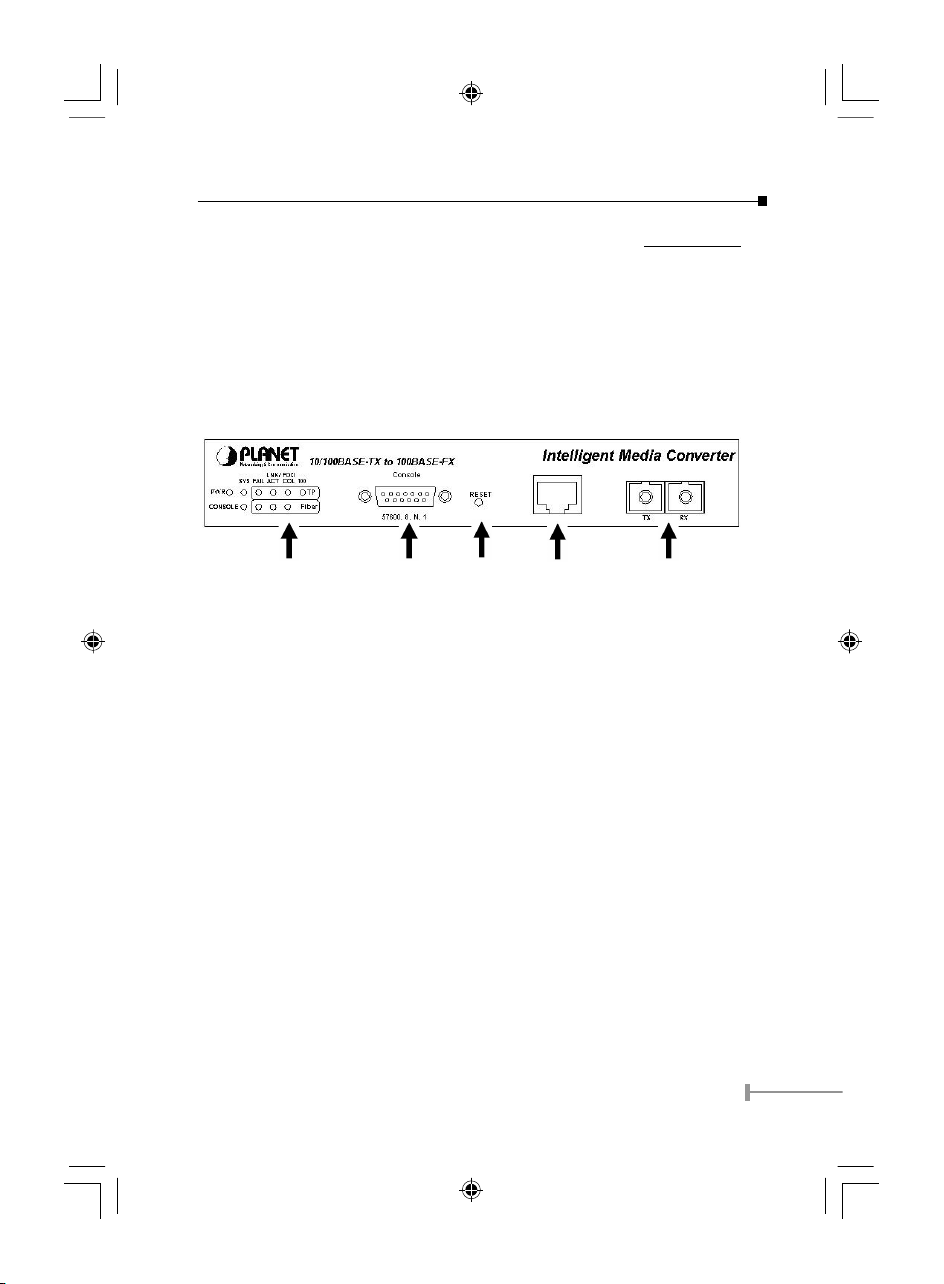
3.1 Front Panel
The gure below shows the front panels of the WFT-20x.
LED Indicatr Console Port Reset Copper port Fiber port
• LED Indicator Panel
Refer to the next section for detailed information.
• Console Port (RS-232)
To congure the device through Terminal Emulation Program via the RS-232 serial
port.
• Reset
To reset all the setting in case of messy setting.
• 10/100Base-TX Twisted-Pair Port
The 10/100Mbps Fast Ethernet port supports automatic MDI/MDIX crossover
detection function gives true ‘plug and play’ capability without the need of confusing
crossover cables or crossover ports.
• Fiber Port
To connect with ber optic cable to the ber port.
EM-WFT20xv1.indd 2004/11/5, �� 12:015
Page 8

6
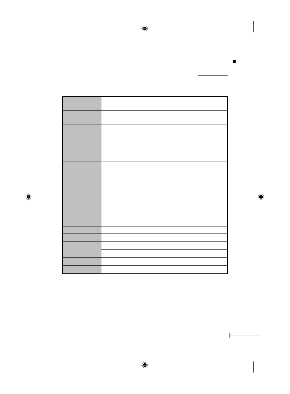
3.2 LED Indicators
PWR Lights Green power is inserted
SYS
(System CPU)
Lights Amber power is inserted and it is fail
CONSOLE
Blinks Green the data is transmitting
Blinks Amber transmitting the wrong data
FAIL
(TP/Fiber)
Lights Amber the link is fail
LNK/ACT
(TP/Fiber)
Lights Green when link to networking Ethernet
Blinks Green when link is activity
FDX/COL
(TP/Fiber)
Lights Green link is in full duplex mode
Lights Off link is in half duplex mode
Blinks Green there is collision happens
100
(Speed for TP)
Lights Green the link speed at 100Mbps
Lights Off the link speed at 10Mbps
Power Notice:
1.The device is a power-required device, it means, it will not work till it is
powered. If your networks should active all the time, please consider using
UPS (Uninterrupted Power Supply) for your device. It will prevent you from
network data loss or network downtime.
2.In some area, installing a surge suppression device may also help to protect
your switch from being damaged by unregulated surge or current to the
media converter.
EM-WFT20xv1.indd 2004/11/5, �� 12:016
Page 9

7
Chapter 4
Configure The Media Converter
This chapter helps you how to congure the WFT-20x.
4.1 Congure Through Terminal Emulator/TELNET Program
4.1.1 Terminal Emulator program setting
The WFT-20x can be accessed using a terminal or terminal emulator attached to the RS232 serial port.
1. Locate correct DB9 serial port cable with female DB9 connector.
2. Attach the DB9 serial port female cable connector to the male DB9 serial port connector
on the chassis system.
3. Attach the other end of the DB9 serial port cable to a remote the workstation.
4. By default, the WFT-20x uses the following serial port parameter values:
Bits per second 57600
Stop bits 1
Data bits 8
Parity NONE
Flow Control NONE
The default Login name and password is both “root”.
4.1.2 TELNET program setting
The WFT-20x system can be accessible using TELNET through LAN.
1. Run TELNET program.
2. Enter the IP address “192.168.1.1" (the factory-default IP address setting).
3. The default Login name and password are both “root”.
EM-WFT20xv1.indd 2004/11/5, �� 12:017
Page 10

8
4.1.3 Congure the Intelligent WFT-20x
4.1.3.1 Main Menu
The main menu shows the setting of the File, General Conguration, System Conguration,
Device Conguration, SNMP Conguration and Device Status.
4.1.3.2 Files
To set the Software Reboot, Factory Reset and Image Update.
4.1.3.2.1 Software Reboot
After conguring the software, you need to reboot the device by pressing the Software
Reboot to change the setting.
4.1.3.2.2 Factory Reset
This function is to set the device back to the factory default setting in case of the messy
setting.
4.1.3.2.3 Image Update
The section is to set the TFTP Server IP Address rst, and the default address was set
to "192.168.1.2". The Image File can be updated by uploading the image le from the
TFTP server.
NOTE:
The content of the image file will write the whole firmware
of the management module, please be sure that the image
file is correct.
EM-WFT20xv1.indd 2004/11/5, �� 12:018
Page 11

9
4.1.3.3 General Congurations
This page is to congure the device name, passwords and location.
• Hardware revision: noted the version of the hardware.
• BIOS revision: noted the version of the BIOS.
• Firmware revision: noted the version of the firmware.
• Change Password: the changing of the admit password.
• Confirm Password: to confirm the setting of admit password.
• System Name: to authorize the device system name.
• Location: to show the device where it is located.
4.1.3.4 System Congurations
This page is for setting the MAC Address, IP Address, Subnet Mask and Gateway
Address.
• MAC Address: will show out the MAC address of the device.
• IP Address: to allocate an IP address for the device, the default IP is “192.168.1.1”.
• Subnet Mask: to set the Subnet Mask, the default is “255.255.255.0”.
• Default Gateway: to set the gateway address, the default is “192.168.1.254”.
EM-WFT20xv1.indd 2004/11/5, �� 12:019
Page 12

10
4.1.3.5 Device Congurations
This page needs to congure the Copper and Fiber Setting.
• Copper Setting: to set the Auto-Negotiation Mode, Duplex mode, Speed, Flow Control and
Link Enable setting.
• Auto-Negotiation: when set to “Auto”, it will detect the speed from other end if it will be
10Mbps or 100Mbps and will set itself to be the same speed, and when set to “Force” then
it can be only set to 100Mbps or 10Mbps.
• Duplex Mode: to set the device runs in Full Duplex mode or Half Duplex mode.
• Speed: to set the device to run in speed of 10Mbps or 100Mbps.
• Flow Control: to enable or disable to flow control of the device.
• Enable: to enable or disable the linkage of the copper (RJ45).
• Fiber Setting: to set the Duplex Mode of the Fiber to be Full duplex or Half duplex mode.
NOTE:
After conguring the system device, need to press the save
button to save the setting.
4.1.3.6 SNMP Congurations
To set the SNMP setting on MIB Browser to monitor the device.
• Get Community Name: to get the device community name (default = public).
• Set Community Name: to set the device community name (default = private).
• Trap Community Name: to authorize the device trap community name (default = public).
• Trap Host IP Address: to set the trap host IP address (same as monitoring station IP ad-
dress).
EM-WFT20xv1.indd 2004/11/5, �� 12:0110
Page 13

11
• Cold Start trap: to set the trap for rebooting the device (default = enable).
• Authentication Fail Trap: to set the warning trap when the community name of the device and
workstation are different (default = enable).
• MC Link Up Trap: to enable the trap that if other device has linked up.
• Warm Start Trap: to enable a trap that if the device was restart.
• MC Broken Trap: to enable the trap that announcing the WFT-20x was destruct.
• MC Link Down Trap: to enable the trap that if the linked of the device was pulled down.
4.1.3.7 Device Status
This page shows that the device’s copper and ber linking status.
4.2 Congure Through Web browser
1. Open up the Internet Web browser.
2. Enter the IP address http://192.168.1.1 (the factory-default IP address setting) to the
URL web address location.
3. Enter the user name and password you have congured (the default Login name and
password are both “root).
4. The web conguration will be shown. Point the selections in the left side of the menu
screen. The menu includes System Reboot, Factory Reset, Image Update, Device
Status, General Conguration, System Conguration, Device Conguration and SNMP
Conguration and that to be explainde in the next section.
EM-WFT20xv1.indd 2004/11/5, �� 12:0111
Page 14

12
4.2.1 System Reboot
After conguring the converter, you need to reboot the device by pressing the System
Reboot to access the new setting.
4.2.2 Factory Reset
This function is to set the device back to the factory default setting in case of the messy
setting.
4.2.3 Image Update
This function allows you to update the rmware on the media converter. Please rst setup
a TFTP server and copy the rmware le to the server’s directory. Enter the server’s IP
on the "TFTP Server IP" section the rmware le name on "Image File" section then click
"Update" to update the converter’s rmware. Please regularly check PLANET web site for
any new available rmware.
NOTE:
The content of the image file will write the whole firmware of
the WFT-20x, please be sure that the image file is correct.
4.2.4 Device Status
This page shows that the device’s copper and ber linking status.
EM-WFT20xv1.indd 2004/11/5, �� 12:0112
Page 15

13
4.2.5 General Conguration
This page is to congure the device name, passwords and location.
• Hardware revision: noted the version of the hardware.
• BIOS revision: noted the version of the BIOS.
• Firmware revision: noted the version of the firmware.
• Change Password: the changing of the administrator password.
• Confirm Password: to confirm the setting of administrator password.
• System Name: to authorize the device system name.
• Location: to show the device where it is located.
4.2.6 System Conguration
This page is for setting or displaying the MAC Address, IP Address, Subnet Mask and
Gateway Address.
• MAC Address: will show out the MAC address of the device.
• IP Address: to allocate an IP address for the device, the default IP is “192.168.1.1”.
• Subnet Mask: to set the Subnet Mask, the default is “255.255.255.0”.
• Default Gateway: to set the gateway address, the default is “192.168.1.254”.
EM-WFT20xv1.indd 2004/11/5, �� 12:0113
Page 16

14
4.2.7 Device Conguration
This page needs to congure the Copper and Fiber Setting.
• Copper Setting: to set the Auto-Negotiation Mode, Duplex mode, Speed, Flow
Control and Link Enable setting.
• Auto-Negotiation: when set to “Auto”, it will detect the speed from other end if it
will be 10Mbps or 100Mbps and will set itself to be the same speed, and when set
to “Force” then it can be only set to 100Mbps or 10Mbps.
• Duplex Mode: to set the device runs in Full Duplex mode or Half Duplex mode.
• Speed: to set the device to run in speed of 10Mbps or 100Mbps.
• Flow Control: to enable or disable the flow control of the device.
• Enable: to enable or disable the linkage of the copper (RJ45).
• Fiber Setting: to set the Duplex Mode of the Fiber to be Full duplex or Half duplex
mode.
NOTE:
After configuring the system device, need to press the save
button to save the setting.
4.2.8 SNMP Conguration
Conguring the SNMP setting on MIB Browser to monitor the device.
• Get Community Name: to get the device community name (default = public).
• Set Community Name: to set the device community name (default = private).
• Trap Community Name: to authorize the device trap community name (default
= public).
• Trap Host IP Address: to set the trap host IP address (same as monitoring station
IP address).
EM-WFT20xv1.indd 2004/11/5, �� 12:0114
Page 17

15
• Cold Start trap: to set the trap for rebooting the device (default = enable).
• Authentication Fail Trap: to set the warning trap when the community name of the
device and workstation are different (default = enable).
• MC Link Up Trap: to enable the trap that if other device has linked up.
• Warm Start Trap: to enable a trap that if the device was restart.
• MC Broken Trap: to enable the trap that announcing the WFT-20x was destruct.
• MC Link Down Trap: to enable the trap that if the linked of the device was pulled
down.
EM-WFT20xv1.indd 2004/11/5, �� 12:0115
Page 18

16
This page is intentionally left blank
EM-WFT20xv1.indd 2004/11/5, �� 12:0116
Page 19
17
Chapter 5
SPECIFICATION
Standards
IEEE802.3 10Base-T
IEEE802.3u 100Base-TX, 100Base-FX
Ports
1 x 10/100 Base-TX port,
1 x 100 Base-FX port
Speed
10/20Mbps for half/full-duplex
100/200Mbps for half/full-duplex
LED Indicators
Unit: Power, System, Console
TP: FAIL, LINK/ACT, FDX/COL, 100M
Fiber: FAIL, LINK/ACT, FDX/COL
Cable
10Base-T: 2-pair UTP Cat. 3,4,5, up to 100 m (328 ft)
100Base-TX: 2-pair UTP Cat. 5, up to 100 m (328 ft)
100Base-FX:
WFT-201, WFT-202 –
62.5/125μm or 50/125μm multi-mode fiber optic up to
2km
WFT-202S15 –
9/125μm single-mode fiber optic up to 15km
Power Consump-
tion
6 Watts (maximum)
Dimensions 190 × 120 × 38 mm (L × W × H)
Power Internal Power 100~240VAC
Temperature
Operating : 0°C ~ 40°C (32°F ~ 104°F)
Storage : -25°C ~ 70°C (-13°F ~ 158°F)
Humidity 10 ~ 90%, non-condensing
Emissions FCC Class B, CE Marking Class B, VCCI Class B
EM-WFT20xv1.indd 2004/11/5, �� 12:0117
Page 20

18
This page is intentionally left blank
EM-WFT20xv1.indd 2004/11/5, �� 12:0118
Page 21

EM-WFT20xv1.indd 2004/11/5, �� 12:0119
Page 22

Part No.:EM-WFT20xv2
EM-WFT20xv1.indd 2004/11/5, �� 12:0120
 Loading...