

Page 1
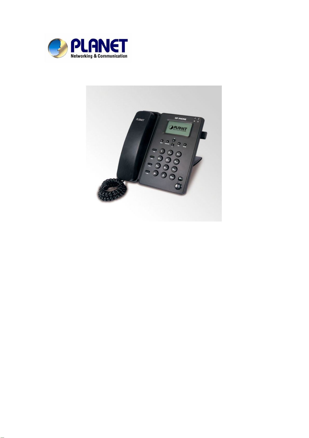
SIP IP Phone
VIP-254T/VIP-254PT
User’s manual
Version 1.0
1
Page 2

Copyright
Copyright (C) 2008 PLANET Technology Corp. All rights reserved.
The products and programs described in this User’s Manual are licensed products of PLANET Technology, This
User’s Manual contains proprietary information protected by copyright, and this User’s Manual and all
accompanying hardware, software, and documentation are copyrighted.
No part of this User’s Manual may be copied, photocopied, reproduced, translated, or reduced to any electronic
medium or machine-readable form by any means by electronic or mechanical. Including photocopying, recording,
or information storage and retrieval systems, for any purpose other than the purchaser's personal use, and without
the prior express written permission of PLANET Technology.
Disclaimer
PLANET Technology does not warrant that the hardware will work properly in all environments and applications,
and makes no warranty and representation, either implied or expr essed, with respect to the quality, performance,
merchantability, or fitness for a particular purpose.
PLANET has made every effort to ensure that this User’s Manual is accurate; PLANET disclaims liability for any
inaccuracies or omissions that may have occurred.
Information in this User’s Manual is subject to change without notice and does not represent a commitment on the
part of PLANET. PLANET assumes no responsibility for any inaccuracies that may be contained in this User’s
Manual. PLANET makes no commitment to update or keep current the information in this User’s Manual, and
reserves the right to make improvements to this User’s Manual and/or to the products described in this User’s
Manual, at any time without notice.
If you find information in this manual that is incorrect, misleading, or incomplete, we would appreciate your
comments and suggestions.
CE mark Warning
The is a class B device, In a domestic environment, this product may cause radio interference, in which case the
user may be required to take adequate measures.
WEEE Warning
To avoid the potential effects on the environment and human health as a result of the presence of
hazardous substances in electrical and electronic equipment, end users of electrical and electronic
equipment should understand the meaning of the crossed-out wheeled bin symbol. Do not dispose of
WEEE as unsorted municipal waste and have to collect such WEEE separately.
Trademarks
The PLANET logo is a trademark of PLANET Technology. This documentation may refer to numerous hardware
and software products by their trade names. In most, if not all cases, their respective companies claim these
designations as trademarks or registered trademarks.
2
Page 3

Revision
User’s Manual for PLANET SIP IP Phone:
Model: VIP-254T/VIP-254PT
Rev: 1.0 (2008, May)
Part No. EM-VIP254V1.0
3
Page 4

TABLE OF CONTENTS
Chapter 1................................................................................................ 6
Introduction............................................................................................ 6
Overview............................................................................................................................6
Package Content...............................................................................................................7
Physical Details.................................................................................................................8
Rear V iew...................................................................................................................8
Front View and Keypad function................................................................................9
Chapter 2 Preparations & Installation.................................................11
Physical Installation Requirement................................................................................11
Administration Interface ...............................................................................................13
Web configuration access:........................................................................................13
Chapter 3 Network Service Configurations....................................... 14
Configuring and monitoring your IP Phone from web browser................................14
Overview on the web interface of IP Phone.............................................................14
Manipulation of IP Phone via web browser .............................................................14
LAN IP address configuration via web configuration interface...............................15
Chapter 4 VoIP IP Phone Configurations........................................... 17
Phone Book settings........................................................................................................17
Speed Dial settings...................................................................................................19
Call Forward.............................................................................................................20
SNTP settings...........................................................................................................20
Volume Setting.........................................................................................................21
Ringer Setting...........................................................................................................22
Block Setting ............................................................................................................22
Dial Plan Settings.....................................................................................................23
Call waiting Settings.................................................................................................25
Hot line Settings.......................................................................................................25
Alarm Settings..........................................................................................................25
LAN Settings............................................................................................................26
PC Settings ...............................................................................................................27
DDNS Settings .........................................................................................................28
VLAN Settings.........................................................................................................29
DMZ Settings ...........................................................................................................29
Virtual Server............................................................................................................30
PPTP Settings...........................................................................................................31
Service Domain Settings ..........................................................................................31
Port Settings..............................................................................................................32
Codec Settings..........................................................................................................33
4
Page 5

Codec ID Setting ......................................................................................................33
DTMF Settings.........................................................................................................34
RPort Settings...........................................................................................................34
Other Settings...........................................................................................................35
STUN settings ..........................................................................................................35
Auto Configuration...................................................................................................36
MAC CIone Setting..................................................................................................36
Tone Settings ............................................................................................................38
Advanced Settings....................................................................................................38
System Authority......................................................................................................39
Save & Reboot..........................................................................................................39
Firmware Upgrade....................................................................................................40
Auto Upgrade ...........................................................................................................40
Reset to Default........................................................................................................42
Reboot without saving..............................................................................................43
Appendix A V oice communications...............................................................................44
Case 1: Voice communication via SIP proxy server _SIP-50...................................44
Case 2: Call Forward Feature_Example 1................................................................45
Case 3: Call Forward Feature_Example 4................................................................46
Appendix B The method of operation guide................................................................48
Call Transfer.............................................................................................................48
3-Way Conference....................................................................................................48
Call Waiting..............................................................................................................48
Switch the Realm (Registration Proxy Server) ........................................................49
Appendix C VIP-254T / VIP-254PT Specifications.....................................................50
5
Page 6

Chapter 1
1
Introduction
Overview
Meeting the next-generation Internet telephony service demands, PLANET Technology provides
feature-rich, toll-quality Internet telephony service solutions. With 802.3af Power over Ethernet (PoE) IP
Phone-VIP-254PT. And the VIP-254T is the cost-effective SIP IP Phone; the VIP-254 series are SIP
2.0 (RFC3261) compliant with SIP digest authentication supports.
The VIP-254T / VIP-254PT ("IP Phone" in the following term) features high-quality speakerphone
technology, and includes an easy-to-use speaker on/off button and call hold/transfer buttons for various
voice services.
The IP Phone has additional features such as built-in PPPoE/DHCP clients, password-protected
machine management, LCD menu display, 3-way conference keys, hands-free speakerphone,
incoming message indicator, and user-intuitive web administration system.
The IP Phone is self-contained, service-integrated, intelligent phone features offering, and powerful
voice processing power. The IP Phone can effortlessly deliver toll voice quality equivalent to the regular
SIP protocol connections utilizing cutting-edge Quality of Service, echo cancellation, comfort noise
generation (CNG) and voice compensation technology. Meanwhile, the dual Ethernet interfaces on the
IP Phone allow users to install in an existing network location without interfering with desktop PC
network connections.
Besides, the IP Phones are ideal solution for office / home use as well as installation for Internet
Telephony Service Provider (ITSP) from leading vendors. It's the delivery platform for IP voice services
that makes benefit from the VoIP technologies in your daily life.
There are models for VIP-254T/VIP-254PT and there are:
VIP-254T: SIP IP Phone
VIP-254PT: 802.3af PoE SIP IP Phone
Product Features
• Simple Installation and administration
Configuration of the IP Phone can be performed in minutes via the LCD menu keypad, or web
interfaces. Using the built-in LCD display, the IP Phone offers user-friendly configuration guidelines,
machine operation status, call status displays, and incoming call identification.
• Feature-rich keypad IP Phone
The IP Phone integrates a high-quality speakerphone with the Call Hold, Forward, Transfer and
Waiting functions and also provides advanced telephone features, such as 3-way conference key,
incoming call history indicator in a much more convenient and functional manner than traditiona l
telephone sets.
6
Page 7

• Dynamic IP address assignment, and voice communication
The IP Phone can act as a PPPoE/DHCP client, automatically obtaining an IP address for Internet
access.
• Various field applications compliant
The IP Phone is capable of handling peer-to-peer and SIP proxy / IP PBX registration,
authentication to interact with major IP PBX/SIP gateway/IP Phone in the market. The IP Phone
offers the most flexibility and interoperability with PLANET and 3rd party VoIP vendors, allowing the
deployment of both simple and complex VoIP networks such as ITSP, PC-to-Phone/Phone-to-PC
or enterprise VoIP environments.
• Standards compliant
The VIP-254T / VIP-254PT complies with SIP 2.0 (RFC3261), interoperates with 3rd party SIP
voice gateways/terminal/software as well as other PLANET VoIP products. Supported Voice
codecs and VoIP technologies are: G.723, G.729ab, G.711u-law/a-law; Voice Activity Detection
(VAD), and the Confort Noise Generation (CNG).
VoIP Features
• SIP 2.0 (RFC3261) compliant
• Peer-to-Peer / SIP proxy calls
• Voice codec support: G.711, G.723.1, G.726, G.729A, G.729B
• Voice processing: Voice Active Detection, DTMF detection/ generation, G.168 echo cancellation
(16mSec.), Comfort noise generation
• In band and out-of-band DTMF support
Package Content
The contents of your product should contain the following items:
VoIP IP Phone
Power adapter
Quick Installation Guide
User’s Manual CD
RJ-45 cable x 1
7
Page 8
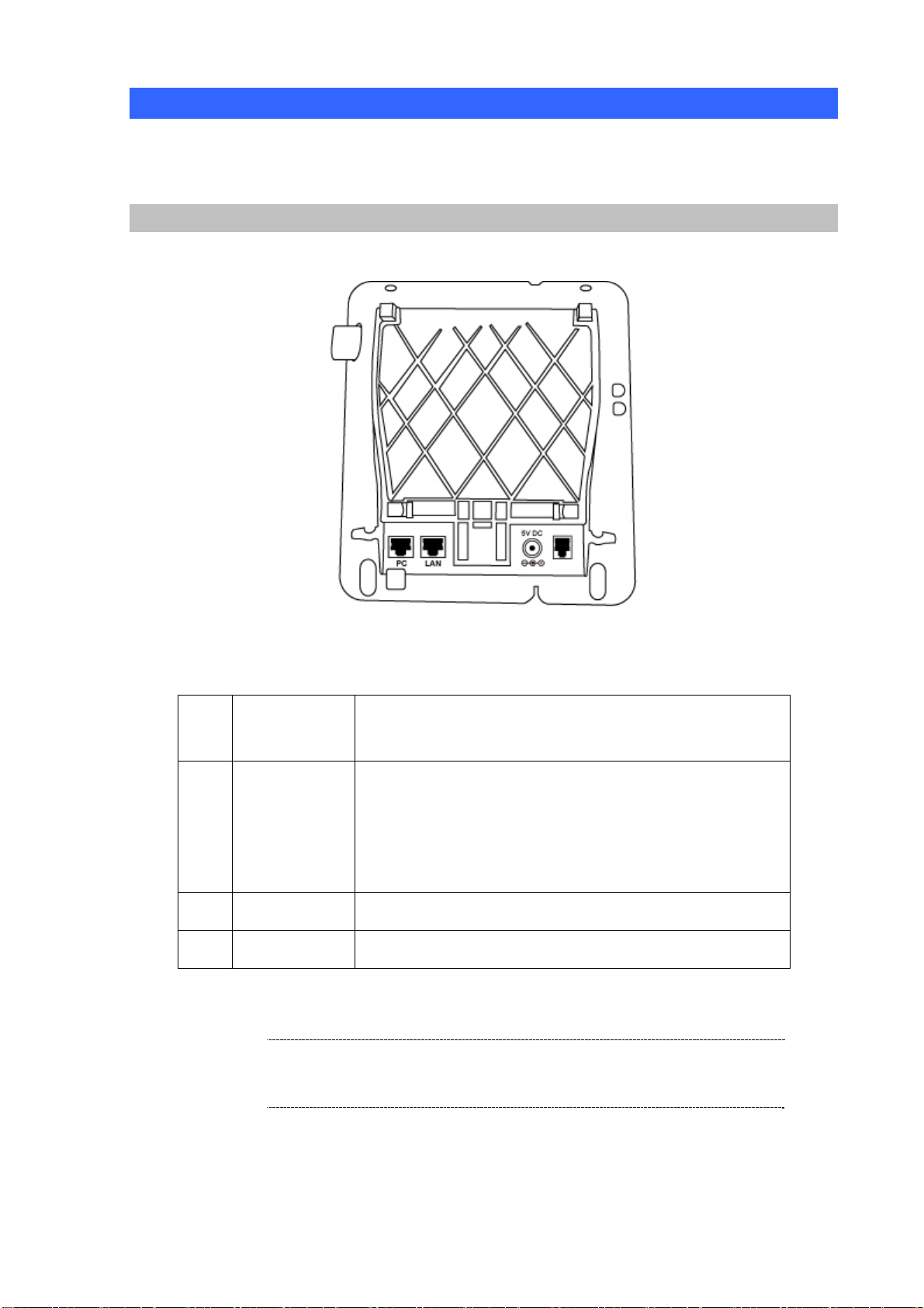
Physical Details
The following figure illustrates the front/rear panel of IP Phone.
Rear View
Rear Panel of VIP-254T/VIP-254PT
1 PC
2 LAN
3 DC 5V
4. Handset
RJ-45 connector, to maintain the existing network structure,
connected directly to the PC through straight CAT-5 cable
RJ-45 connector, for Internet access, connected directly to
Switch/Hub through straight CAT-5 cable.
The LAN interface also can be connected with 802.3af PoE
switch or converter for power supply (VIP-254PT)
5V DC Power input outlet
RJ-11 connector, connected directly to the Handset.
LNote
For VIP-254PT, either PoE or AC adapter can be deployed at
one time
8
Page 9

Front View and Keypad function
Front Panel of VIP-254T/VIP-254PT
Keypad Description
1 LCD Display
2 MENU
3
4 ENTER
5 CONTACTS
6 FLASH
7 CONF
▲ ▼
Menu and all status shall be displayed for users.
To bring out the menu selection while IP Phone is in idle state.
This is Up ▲ / Down ▼ key and volume setting when
off-hook off.
Show the calls history when on-hook.
To be used as confirm configuration or enter sub-menu.
Enter the phone book selection.
To transfer an active call (incoming call answered or outgoing
call accepted) to another devices.
Press this button can make conference function.
8 FWD
9 DEL
9
To carry out forward function.
Press to delete digits when at configuration mode or input
phone numbers.
Press to mute sounds when at talk mode.
Page 10

Press to dial the last dialed number when the IP Phone is
10 RD
off-hooked.
To switch between the usage of the handset and the speaker
11 Handfree
devices.
12 Hold
To hold the conversation.
10
Page 11
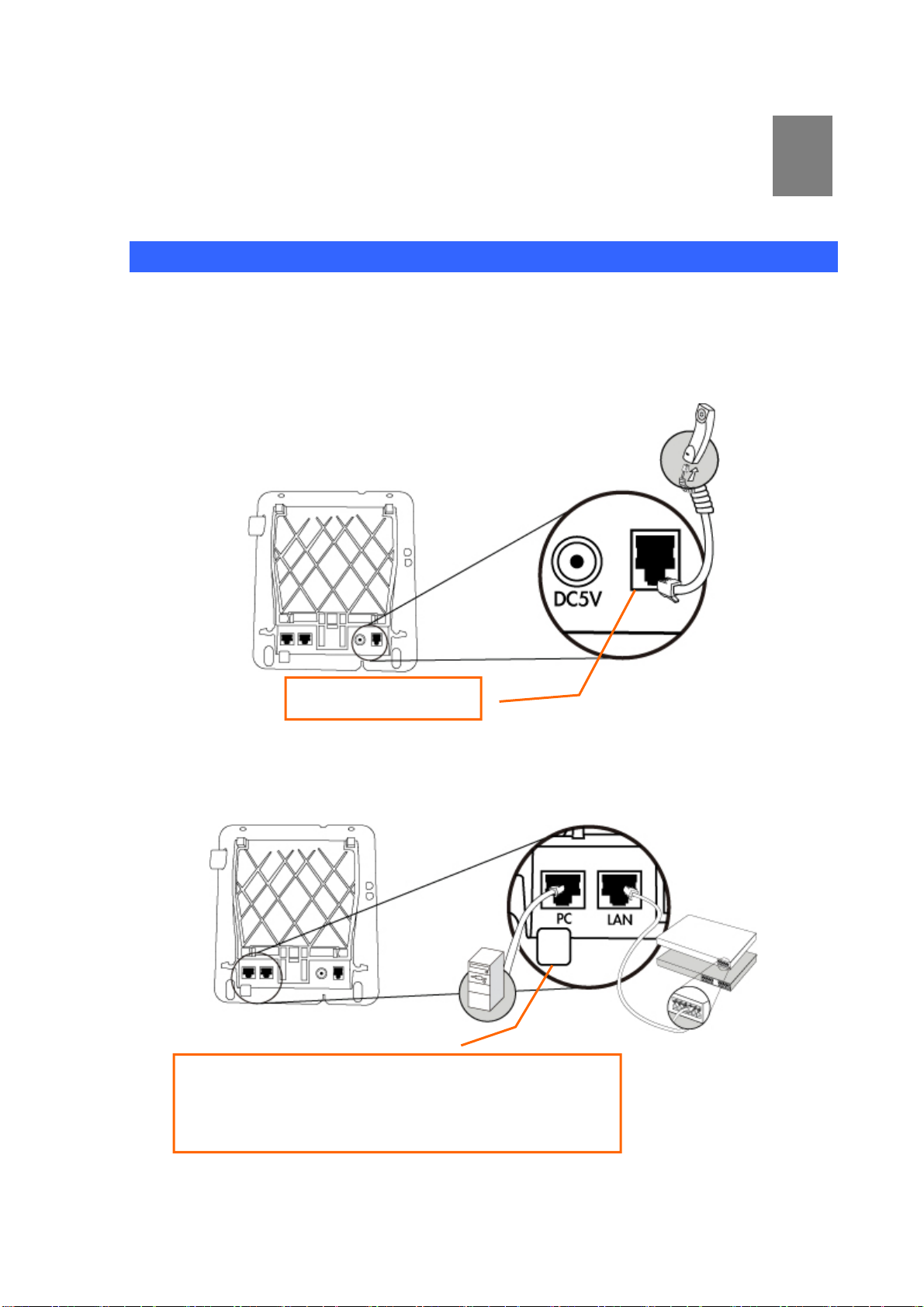
Chapter 2
Preparations & Installation
Physical Installation Requirement
VIP-254T: SIP IP Phone (2 x RJ-45)
VIP-254PT: 802.3af PoE SIP IP Phone (2 x RJ-45, 1 x PoE for LAN interface)
Step 1: Connecting Handset
2
Step 2: Connecting Power AC Power and Network
Plug the Ethernet cable into the back of the base station.
Plug the other end of the Ethernet cable into your already
prepared network connection.
Handset
11
Page 12
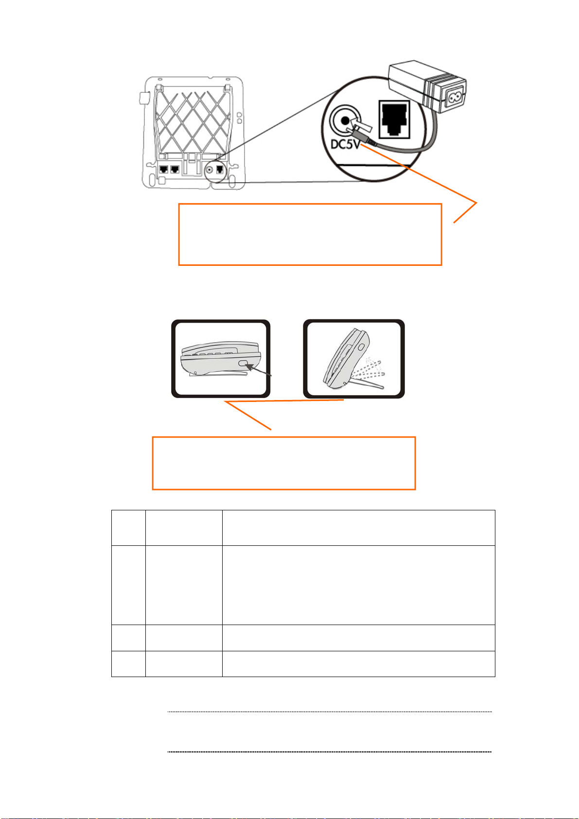
Power Adapter (5V DC)
NOTE: Use only the power adapter shipped with the
unit to ensure correct functionality.
Step 3: Adjust the stand angle.
ÍNote
Press and hole the button of right side to change the
stand mount angle.
1 PC
2 LAN
3 5V DC
4 Handset
1. For VIP-254PT, either PoE or AC adapter can be deployed
at one time
RJ-45 connector, to maintain the existing network structure,
connected directly to the PC through straight CAT-5 cable
RJ-45 connector, for Internet access, connected directly to
Switch/Hub through straight CAT-5 cable.
The LAN interface also can be connected with 802.3af PoE
switch or converter for power supply (VIP-254PT only)
5V DC Power input outlet
RJ-11 connector, connected directly to the Handset.
12
Page 13
Administration Interface
The IP Phone provides GUI (Web based, Graphical User Interface) for machine management and
administration. Key pad administration also available for simple configuration.
Web configuration access:
To start IP Phone web configuration, you must have one of these web browsers installed on computer
for management
• Microsoft Internet Explorer 6.0.0 or higher with Java support
Default IP address of IP Phone is 192.168.0.1. You may now open your web browser, and insert
http://192.168.0.1 in the address bar of your web browser to logon IP Phone web configuration page.
IP Phone will prompt for logon username/password, please ente r: root / null (no p asswo rd) to continue
machine administration.
ÍNote
In order to connect machine for administration, please
locate your PC in the same network segment (192.168.0.x)
of IP Phone. If you’re not familiar with TCP/IP, please refer
to related chapter on user’s manual CD or consult your
network administrator for proper network configurations.
13
Page 14
Chapter 3
3
Network Service Configurations
Configuring and monitoring your IP Phone from web browser
The IP Phone integrates a web-based graphical user interface that can cover mo st configurations
and machine status monitoring. Via st andard, web browser, you can configure and check machine
status from anywhere around the world.
Overview on the web interface of IP Phone
With web graphical user interface, you may have:
More comprehensive setting feels than traditional command line interface.
Provides user input data fields, check boxes, and for changing machine configuration settings
Displays machine running configuration
To start IP Phone web configuration, you must have one of these web browse rs installed on computer
for management
Microsoft Internet Explorer 6.0.0 or higher with Java support
Manipulation of IP Phone via web browser
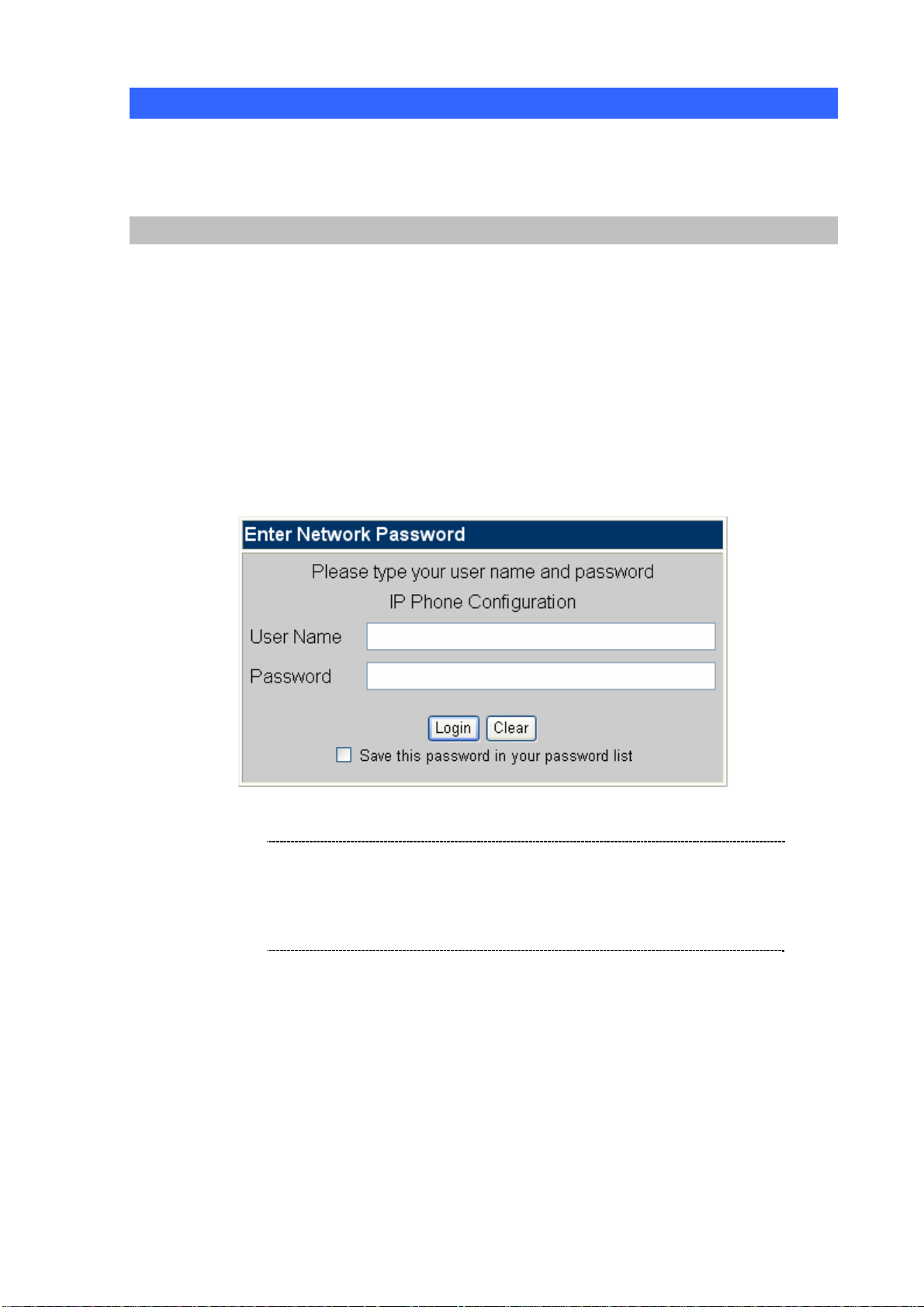
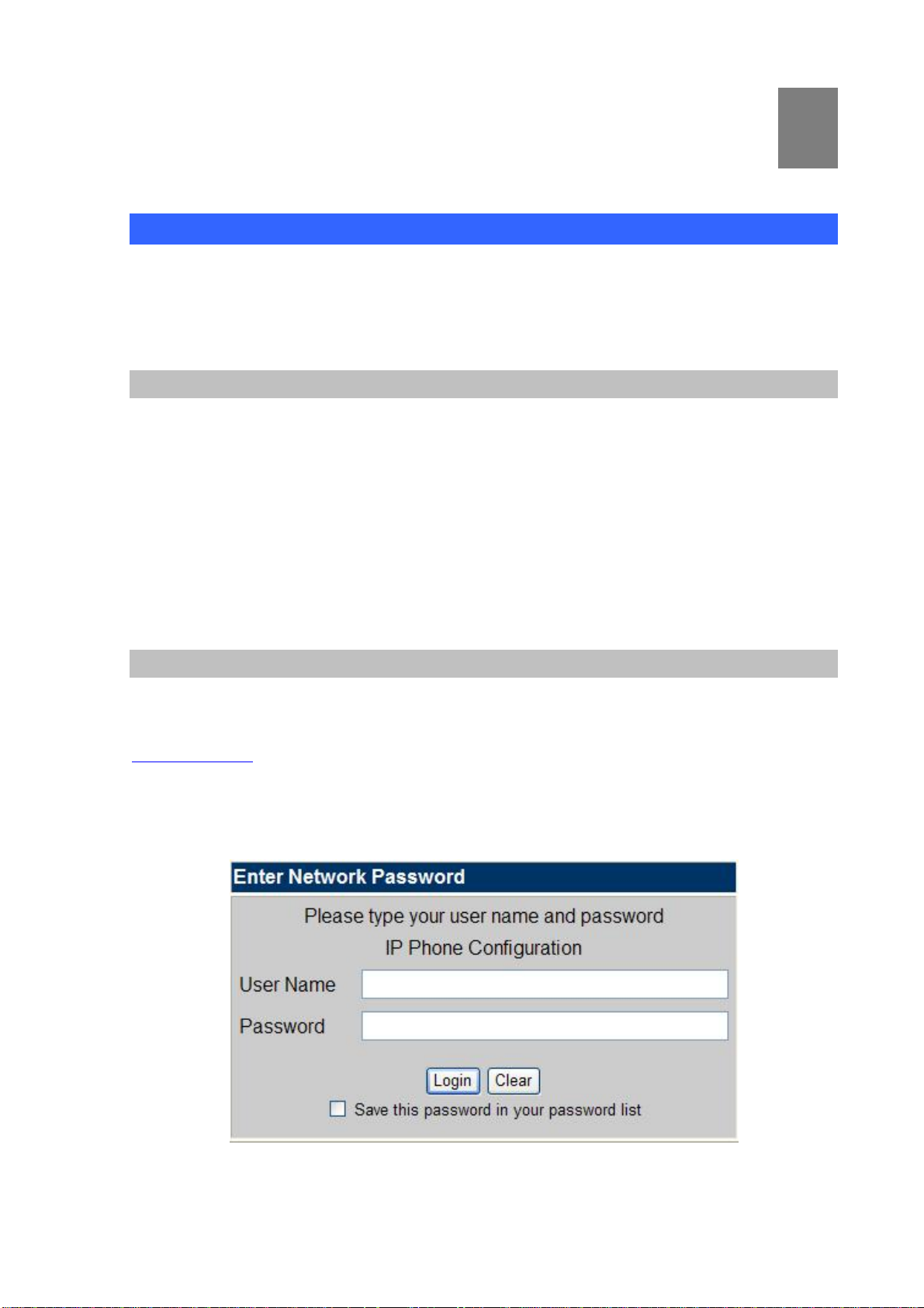
Log on IP Phone via web browser
After TCP/IP configuration s on your PC, you may now open your web browser, and input
http://192.168.0.1
IP Phone will prompt for logon username/password: root / null (without pass word)
to logon IP Phone web configuration page.
IP Phone log in page
14
Page 15
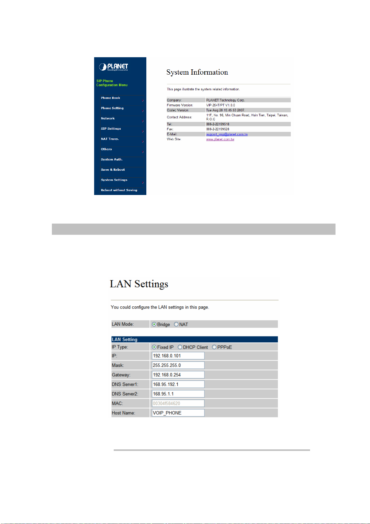
When users login the web page, users can see the IP Phone system information like firmware version,
company…etc in this main page.
IP Phone main page
LAN IP address configuration via web configuration interface
Execute your web browser, and insert the IP address (default: 192.168.0.1) of VIP in the address bar.
After logging on machine with username/password (default: root / no password), browse to “Network”
--> “LAN Settings” configuration menu:
Parameter Description
IP address LAN IP address of IP Phone
Default: 192.168.0.1
15
Page 16
Subnet Mask LAN mask of
Default: 255.255.255.0
IP Phone
Default Gateway Gateway of
IP Phone
Default: 192.168.0.254
After confirming the modification you’ve done, Please click on the Submit button to apply settings and
browse to “Save & Reboot” menu to reboot the machine to make the settings effective.
Connection Type Data required.
Fixed IP
DHCP client
PPPoE
L Hint
Please consult your ISP personnel to obtain proper PPPoE/IP
address related information, and input carefully.
If Internet connection cannot be established, please check
the physical connection or contact the ISP service staff
for support information.
In most circumstances, it is no need to configure the DHCP
settings.
The ISP will assign IP Address, and related information.
The ISP will assign PPPoE username / password for Internet
access,
Save Modification to Flash Memory
Most of the IP Phone parameters will take effective after you modify, but it is just temporary stored on
RAM only, it will disappear after your reboot or power off the IP PHone, to save the parameters into
Flash ROM and let it take effective forever, please remember to press the Save & Reboot button after
you modify the parameters.
16
Page 17

Chapter 4
4
VoIP IP Phone Configurations
Phone Book settings
IP Phone can set up 140 records of Phone Book. User can make calls via Phone Book feature of IP
Phone.
Field Description
Phone Book Page
Phone
Name
URL
Select
The default is Page 1. It can select Page1 ~ Page 14
to look round Phone Book records.
The record number from 0 ~ 139, it can set up 140
records in total.
The name of Phone Book records, it only can input
numerals.
Fill in the outgoing number (Line Number) or IP
address.
To select this record.
17
Page 18

If you need to add a phone number into the Phone Book list, you need to input the position, the name,
and the phone number (by URL type). When you finished a new phone list, just click the “Add Phone”
button.
If you want to delete a phone number, you ca n select the phone number you want to delete then click
“Delete Selected” button.
If you want to delete all phone numbers, you can click “Delete All” button.
For Example:
STEP 1:
IP Phone had added the above phone numbers. User press Phone Book button from keypad
then the LCD screen will show below:
Search: [ 3]
STEP 2:
Press OK button to enter the Phone Book menu. The LCD screen will show the Phone Book
records pervious made.
STEP 3:
Selecting the recorder you want to dial and press OK button. It sill show the detail information as
00 202
01 206
below:
18
Page 19

STEP 4:
Pick up the telephone handset or press Handfree button to dial to this telephone.
202
192.168.1.2:5062
IP Dialing.. 1
192.168.1.2:5062
Speed Dial settings
In Speed Dial setting function you can add/delete Speed Dial number. You can input maximum 10
entries speed dial list. You can setup the Speed Dial number. If you want to use Speed Dial you just dial
the speed dial number (from 0~9) and follow the “#” key.
If you need to add a phone number into the Speed Dial list, you need to input the position, the name,
and the phone number (by URL type). When you finished a new phone list, just click the “Add Phone”
button.
If you want to delete a phone number, you ca n select the phone number you want to delete then click
“Delete Selected” button.
If you want to delete all phone numbers, you can click “Delete All” button.
19
Page 20

Call Forward
This page defines Call Forward function. You can setup the phone number you want to forward in this
page. There are three type of Forward mode. You can choose All Forward, Busy Forward, and No
Answer Forward by click the icon.
All Forward: All incoming call will forward to the number you chosen. You can input the name and the
phone number in URL field. If you select this function, then all the incoming call will direct forward to the
speed dial number you choose.
Busy Forward: If you are on the phone, the new incoming call will forward to the number you choosed.
You can input the name and the phone number in URL field.
No Answer Forward: If you can not answer the phone, the incoming call will forward to the number you
chosen. You can input the name and the phone number in URL field. Also you have to set the Time Out
time for system to start to forward the call to the number you choosed.
When you finished the setting, please click the Submit button.
Call Forward function for VIP-254T/VIP-254PT
SNTP settings
This page defines the primary and second SNTP Server IP Address, to get the date/time information.
Also you can base on your location to set the Time Zone, and how long need to synchronize again.
When you finished the setting, please click the Submit button.
20
Page 21

Volume Setting
This page defines the Handset Volume, Ringer Volume, and the Handset Gain. When you finished the
setting, please click the Submit button.
Handset Volume is to set the volume for you can hear from the handset.(Handfree mode)
Speaker Volume is to set the volume for you can hear from the speaker.
Ringer Volume is to set the ringer volume for you can hear.
Handset Gain is to set the volume send out to the other side’s handset.
Speaker Gain is to set the volume send out to the other side’s handset from the microphone. (Handfree
mode)
Volume Settings for VIP-254T/VIP-254PT
21
Page 22

Ringer Setting
This page defines the user can set the tinkle of bells when someone ring your IP Phone. If want to set
ringer, it need to enable Ringer function and select the Ringer Type you wanted . There are four Ringer
Types can b e chosen. When you finished the setting, please click the Submit button.
Block Setting
This page defines the Block Setting to keep the phone slience. You can choose Always Block or Block a
period.
Always Block: All incoming call will be blocked until disable this feature.
Block Period: Set a time period and the phone will be blocked during the time period. If the
time is large than the “To” time, the Block time will from Day 1 to Day 2.
When you finished the setting, please click the Submit button.
“From”
22
Page 23

Dial Plan Settings
This page defines the Dial Plan Setting function. This function is wh en you input the phone number by
the keypad but you don’t need to press “#”. After time out the system will dial directly.
Field
Drop Prefix
Replace rule
+
Dial Now
Description
The rule of add or replace code. If setup as No, it will add the prefix
number prior to the identification number. If setup as Yes, it will
replace the identification number .
The prefix number. It only accept the numeral a nd the max length is 8.
The identification number. It can accept the numeral or symbol and
the max length is 40.
Symbol: It only accept the [+], [x]
+: It means as “or”. For example, [123+456+334+5xx] even if
[123 or 456 or 334 or 5xx]
x: It is equal to 0~9. For example, [5xx] even if the number
begin 5.
If the dialing number are match with this field, it will dial out and need
not to press the “#” key to end the dialing. It accepts the numeral or
symbol, and the max length are 124.
LNote: The starting number ca n’t be the “0”. For example, if the
number is “0xxxx”, because the starting number is “0”, so that the
23
Page 24

system will ignore this dial plan.
Auto Dial Time
Use # as send key
Use * for IP dialing
Stop dialing after seconds then send dial number out.
If setup as Yes, the system sill stop to receive the dialing number
when receive the [#] key. The system also will to determine the Auto
Dial Time, it will carry out the calling if there isn’t receive the digit after
the Auto Dial Time.
If setup as No, the system just according to the Auto Dial Time to
determine the end time.
If setup as Yes, the system will look on [*] as [.]. For example, if dial
the “192*168*0*100#”, it will dial out as “192.168.0.100#”.
If setup as No, it just look on [*] as [*]. For example, if dial the “700*#”,
it will dial out as “700*#”.
Descriptions of example:
Example_1: Drop prefix: No, Replace rule 1: 002, +: 1234+4321 (No limit the digit length)
1. If the dialing number is start as “1234”, it will add the 002 at begin. The real dialing number is
[0021234…].
2. If the dialing number is start as “4321”, it will add the 002 at begin. The real dialing number is
[0024321…].
Example_2: Drop prefix: Yes, Replace rule 2: 006, +: 002+003+004 (No limit the digit length)
1. If the dialing number is start as “002”, it will replace 002 by 006. The real dialing number is
[006…].
2. If the dialing number is start as “003”, it will replace 003 by 006. The real dialing number is
[003…].
Example_3: Drop prefix: No, Replace rule 3: 007, +: 5xxx+35xx (Has limit the digit length)
1. If the dialing number start as “5” and follow 3 digits, it will add the 007 at begin. The real
dialing number is [0075xxx].
2. If the dialing number start as “35” and follow 2 digits, it will add the 007 at begin. The real
dialing number is [00735xx].
Example_4: Dial Now: *xx+#xx+11x+xxxxxx
1. If the dialing number is match with the rule of “*xx”, it will send out the dialing number directly.
For example, *00/ *01/ *02…*99.
2. If the dialing number is match with the rule of “#xx”, it will send out the dialing number directly .
For example, #00/ #01/ #02…#99.
3. If the dialing number is match with the rule of “11x”, it will send out the dialing number directly .
For example, 111/ 112/ 113…119.
4. If the dialing number is match with the rule of 8 digits, it will send out the dialing number
directly. For example, 12345678.
LNote
If enable the Routing function and the dialing number is
match with Routing rule, machine will carry out the Routing
function and to skip over the below Drop prefix and Replace
rule functions.
24
Page 25

Call waiting Settings
When you are talking with other people, You can choose If you want to hear the notice when there is a
new coming call. If the call waiting function is On, if there is a new incomeing call, you will hear the call
waiting notice in your current call. If you set the function to Off, then you will not hear any notice.
Hot line Settings
This page defines the Hot line setting in this page. When user pick up the handset, the device will call to
the specific number automatically.
Use Hot Line: Click Enable to carry the Hot line function out.
Hot line number: The hot line number, it can input the IP address or registration number.
Alarm Settings
This page defines the Alarm setting in this page. It provides the alarm function, and it can set up the
Alarm Time to get the telephon e ringed up every day.
Alarm: The default is Off. If set up as On, the telephone will ringed up at the specific time.
Alarm Time: It can set up the system prompt time with 24 hours.
Current time: The next alarm time.
25
Page 26

LAN Settings
This page defines the LAN setting in this page.
LAN Mode: The default is Bridge mode, and it also provides NAT mode.
Bridge: When set as is mode, the LAN and PC ports are in the same network segment.
NAT: The LAN and PC ports are in the different network segment, and PC port could enable
the DHCP Server function to allot the IP address.
IP Type: The default is Fixed IP, and it also provides DHCP Client and PPPoE connection modes.
Fixed IP: It could setup the IP address manual.
DHCP Client: It will acquire the IP address automatically.
PPPoE: It will use the PPPoE connection method.
IP: The IP address
Mask: The sub net address
Gateway: The default gateway address
DNS Type: The default is Fixed mode, it could setup the DNS mode to manual or auto detection.
DNS Server1: The default is 168.95.192.1, it could setup the first DNS server address.
DNS Server2: The default is 168.95.1.1, it could setup the second DNS server address.
MAC: The MAC of LAN port
Host Name: The product model
User Name: The PPPoE connection account name. It could inpout numeral or character, the maximum
date length are 63.
Password: The PPPoE connection account password. It could inpout numeral or character, the
maximum date length are 63.
26
Page 27

PC Settings
This page defines the PC setting in this page.
IP: The IP address of PC port. (In the Bridge mode, the Default IP: 192.168.123. 1)
Mask: The sub net address. (Default: 255.255.255.0)
MAC: The MAC of PC port
DHCP Server: It will allot the IP address automati call y when enabke this function.
Start IP: Start IP of lease table
End IP: End IP of lease table. Network device connecting to the PC port can dynamic obtain the IP in
the range between start IP and end IP
Lease Time: DHCP server lease time
27
Page 28

DDNS Settings
This page defines the DDNS setting in this page. You need to have the DDNS account and input the
informations properly. You can have a DDNS account with a public IP address then others can call you
via the DDNS account. But now most of the VoIP applications are work with a SIP Proxy Server. When
you finished the setting, please click the Submit button.
28
Page 29
VLAN Settings
This page defines the VLAN setting in this page. This function needs to co-operate with network
devices which have VLAN function.
VLAN Packets: If setup as On, it could receive VLAN messages.
VID (802.1Q/TAG): Dispose VLAN ID is add a Tag header after realize enable the VLAN function. The
realized voice packets transfer at the same VLAN. The prerequisite is it must the
same as VLAN of upper switch. The value range are 2~4094.
User Priority (802.1P): To setup the user priority.
CFI: To indicate the Canonical Format.
If CFI=1, it means the header label include RIF field, and the NCIF flag valus of RIF will to
decide the MAC address is Canonical Format or Non-Ca nonical Format in frame information.
If CFI=0, it means the header label does not include RIF field, and the MAC address is
Canonical Format in frame information.
DMZ Settings
This page defines the DMZ setting in this page.
DMZ: If setup as On, all of packets (expect SIP packets) will send to the specific IP address.
DMZ Host IP: The DMZ host IP address.
29
Page 30

Virtual Server
This page defines the Virtual Server setting in this page. You could define 24 virtual service information
in this page. When you finished the setting, please click the Submit button.
Virtual Server Page: There are total page1 to page 3. It could choose the page which want to go over .
Num: The serial number. There are total 24 records from Num 0 to 23.
Enable: The activate status. The default is Disable, this re cord will been activate if enable.
Protocol: The TCP or UDP communication protocol.
Internal Port: For corresponding the internal port.
External Port: For corresponding the external port.
Server IP: To input the Server IP address.
30
Page 31
PPTP Settings
This page defines the PPTP setting in this page. You could setup the PPTP Server connection
information. When you finished the setting, please click the Submit button.
Service Domain Settings
This router comes with the built-in firewall based on the advanced technology of Stateful Packet
In Service Domain Function you need to input the account and the related informations in this page,
please refer to your ISP provider. Y ou can registe r three SIP account in the Phon. You can dial the VoIP
phone to your friends via first enable SIP account and receive the phone from these three SIP
accounts.
First you need click Active to enable the Service Domain, then you can input the following items:
Display Name: you can input the name you want to display.
User Name: you need to input the User Name get from your ISP.
Register Name: you need to input the Register Name get from your ISP.
Register Password: you need to input the Register Password get from your ISP.
Domain Server: you need to input the Domain Server get from your ISP.
Proxy Server: you need to input the Proxy Server get from your ISP.
Outbound Proxy: you need to input the Outbound Proxy get from your ISP. If your ISP does not
provide the information, then you can skip this item.
You can see the Register St atus in the Status item. If the item shows “Registered”, then your Phone
Adapter is registered to the ISP, you can make a phone call direcly.
If you have more than one SIP account, you can following the steps to regi ster to the other ISP.
When you finished the setting, please click the Submit button.
31
Page 32

LNote:
IP Phone can register to three different SIP Proxies at the same time. It can receive any one of
different SIP accounts inco ming call, and it can switch to any one SIP accounts for making calls
through input the switch code.
Realm switch code:
1*: Realm 1
2*: Realm 2
3*: Realm 3
For example: The default is realm 1, input the
the telephone set. It will switch to realm 2, and it can make the SIP calls via realm 2.
2* (Follow by the # key) from keypad and hang up
Port Settings
This page defines the SIP and RTP port number in this page. Each ISP provider will have different
SIP/RTPport setting, please refer to the ISP to setup the port number correctly. When you finished the
setting, please click the Submit button.
32
Page 33

Codec Settings
This page defines the Codec priority, RTP packet length, and VAD function in this page. You need to
follow the ISP suggestion to setup these items. When you finished the setting, please click the Submit
button.
Codec ID Setting
This page defines the Codec ID. Sometimes 2 VoIP device with different Codec ID will cause the
interoperability issue. If you are talking with others got some problems, you may ask the other one what
kind of Codec ID he use then you can change your Codec ID. When you finished the setting, please
click the Submit button.
33
Page 34

DTMF Settings
This page defines the DTMF parameters. Yyou can setup the InBand DTMF, 2833 Out-Band DTMF and
Send DTMF SIP Info Enable/Disable in this page. To change this setting, please following your ISP
information. When you finished the setting, please click the Submit button.
RPort Settings
This page defines the RPort Enable/Disable in this page. To change this setting, please following your
ISP information. When you finished the setting, please click the Submit button.
34
Page 35

Other Settings
This page defines the Hold by RFC, Voice/SIP QoS and other settings in this page. To change these
settings please following your ISP information. When you finished the setting, please click the Submit
button.
Hold by RFC: The default is disable, and to start up communication hold back function (RFC definition).
Set enable to start up the Hold by RFC function.
Voice QoS (Diff-Serv): The Voice QoS feature.
SIP QoS (Diff-Serv): The SIP QoS feature.
The QoS setting is to set the voice packets’ priority. If you set the value higher than 0, then the voice
packets will get the higher priority to the Internet. But the QoS function still need to cooperate with the
others Internet devices.
SIP Expire Time: To setup the registration interval time.
Use DNS SRV : The default is disable, and use DNS SRV mode. Set enable to use DNS to SRV mode
to search the host information.
Send Keep Alives Pcaket: To deliver the packets on a regular time schedule to keep NAT port could
open continued.
Keep Alives Period: To setup the schedule time for delivering the packets.
Jitter Buffer: To setup the Jitter Buffer size, and the unit is packet. It needs to refer to the Frame size of
Codec.
STUN settings
This page defines the STUN Enable/Disable and STUN Server IP addres s in this page. This function
can help your Phone Adapt er working properly behind NAT. To change these settings please following
your ISP information. When you finished the setting, please click the Submit button.
35
Page 36

Auto Configuration
This page defines the Auto Configuration (Auto Provision) setting. IP Phone supports TFTP, FTP, HTTP
function in total.
MAC CIone Setting
This page defines the MAC Clone Enable/Disable. This function will copy the MAC address from NIC
(Network Interface Card) which placed in PC to LAN port of IP Phone. That because some ISP will limit
the MAC address for PPPoE dial-up connection.
36
Page 37

Please refer to the following operate procedures for more understandings to carry out the MAC Clone
function.
1. Please login IP Phone and browse to “Network -> LAN Settings” page. To switch the LAN mode to
NAT mod e then press Save&Reboot button to save the settings and reboot machine.
2. Please make sure the network cable of your PC directly connect with PC port of IP Phone, then
re-login IP Phone. (In the NAT mode, the default IP address of PC port is http://192.168.123.1
)
3. Please browse to “Advanced Settings -> MAC Clone Setting” page and enable the MAC Clone
function.
4. IP Phone will prompt if sure want to clone the MAC of your PC to the LAN port of IP Phone.
5. After Save&Reboot, the MAC of LAN port will become to PC’s original MAC address.
37
Page 38

Tone Settings
This page defines the Tone settings. This function can setup the related parameters of Dial Tone, Ring
Back Tone, Busy Tone, Error Tone and Insert Tone. When you finished the setting, please click the
Submit button.
Advanced Settings
This page defines the advanced functions. When you finished the setting, please click the Submit
button.
ICMP Not Echo: This function can disable echo when someone ping this device, it can avoid haker try
to attack the device.
Send Anonymous CID: If enable this function, machine will to start the calling hidden function, and it
will not send the related Caller information. (The Registration Server also need
support this function)
Management from WAN: If enable this function, only WAN be able to connect to the management GUI
Send Flash event: There are provide two flash formats: DTMF Event and SIP Info.
Encryption Type: There are provide seven encrypt formats: INFINET, AVS, WALKERSUN1,
WALKERSUN2, CSF1, CSF2, GX and VGX. (The Registration Server also need support
this function)
Encryption Key: The encryption key is use to authentication data transmitted in the SIP network.
PPPoE retry period: If PPPoE dial-up connection fail, machine will retry the dial-up motion after this
time.
System Log Server: Machine could send the system logs to the specific Syslog Server. It can input the
IP or Domain address.
System Log Type: There are seven Syslog types: Call Statistics, General Debug, Call Statistics +
General Debug, SIP Debug, Call Statistics + SIP Debug, General Debug + SIP
Debug and All.
38
Page 39

System Authority
In System Authority you can change your login password.
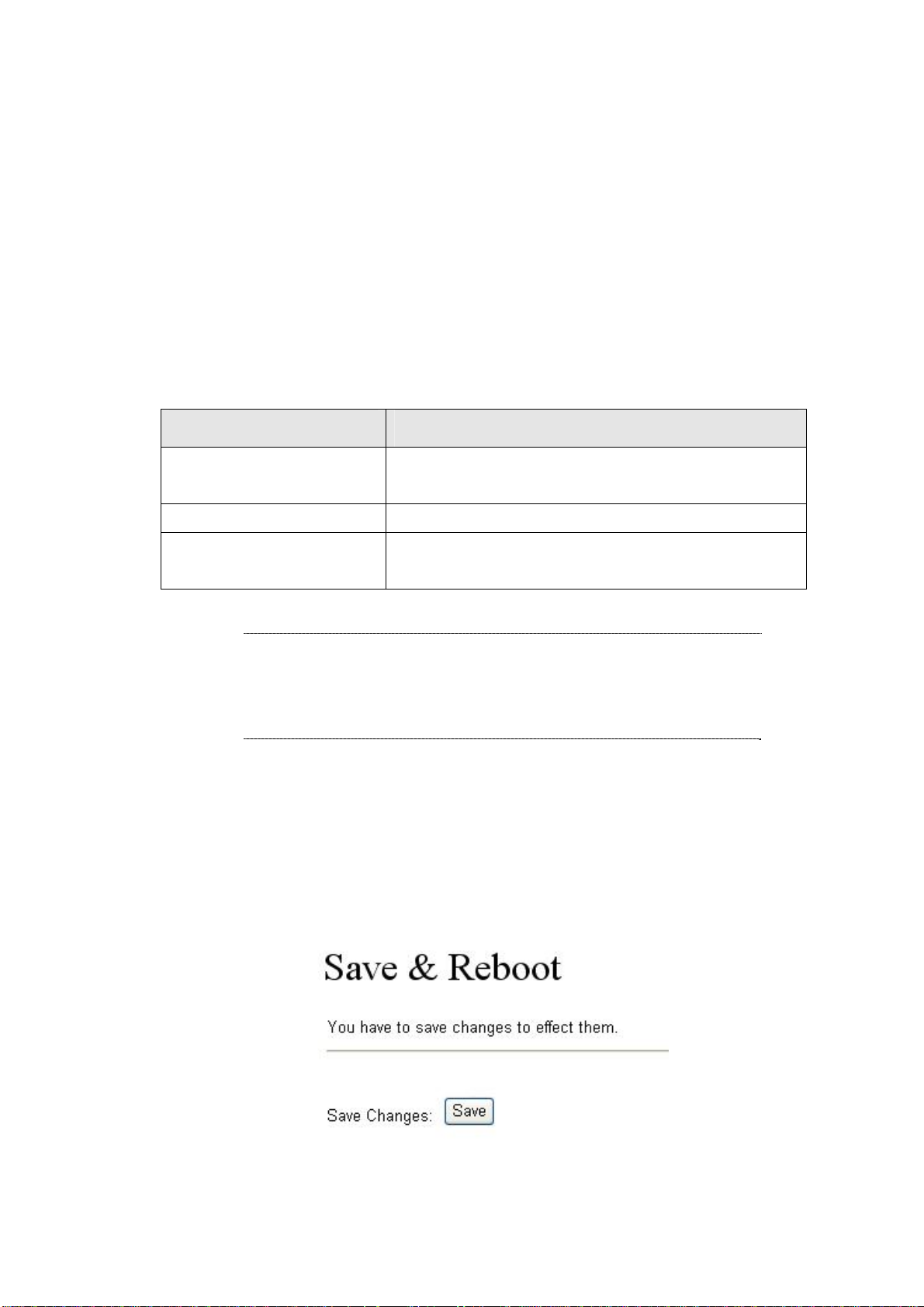
Save & Reboot
In Save & Reboot you can save the changes you have done. If you want to use new setting in the IP
Phone, you have to click the Save button. After you click the Save button, the IP Phone will
automatically restart and the new setting will effect.
39
Page 40

Firmware Upgrade
In Firmware Upgrade function you can update new firmware via HTTP or TFTP methods in this page.
You can ugrade the firmware by the following steps:
Select the upgrade method and the firmware code type, AP or DSP code.
Click the “Browse” button in the right side of the File Location or you can type the correct path and the
filename in File Location blank.
Select the correct file you want to download to the device then click the Update button.
LNote:
After firmware loaded, the unit will be reboot, and Default IP address of the customized firmware:
http://192.168.0.1
Auto Upgrade
The device can update new firmware with the gz or ds file format automatically by the Auto Upgrade
function.
; login name/password: root/null (no password)
40
Page 41

Field Descriptions
Update via
TFTP Server
TFTP Path
HTTP Server
HTTP File Path
FTP Server
FTP Username
FTP Password
FTP File Path
Check new firmware
There are TFTP/ FTP and HTTP three ways to provide the auto
upgrade function.
Input the TFTP Server address, and it could input the IP or Domain
Name form.
Set up the file path.
Input the HTTP Server address, and it could input the IP or Domain
Name form.
Set up the file path.
Input the FTP Server address, and it could input the IP or Domain
Name form.
The login username.
The login password
Set up the file path.
The device will according to the below ways to check the new
firmware.
- Power On and Scheduling: The machine will check the
41
Page 42

new firmware when power on and following the scheduling
date and time.
- Scheduling only: The machine will only follow the
scheduling date and time to check the new firmware.
Scheduling (Date)
Automatic Update
Firmware File Prefix
Next update time
LNote:
If the Check new firmware field selected to Power On, the machine will chck the new
firmware accoeding the scheduling time/date and power on. If there are new firmware can
be upgraded, the machine won’t carry firmware update out automatic. The machine will
show the [Found New s/w] message on LCD. Then press [Menu] button for entrying the
The machine will check the new firmware between the time range
by random.
There are Notify only and Automatic ways to update.
- Notify only: If there are new firmware, the IP Phone will
send the “Be Be Be” sounds when pick up the handset to
prompt there are new firmware.
- Automatic: The device will carry firmware update out
automatically.
It will check the information of model name.
It will show the next check date and time.
main menu and select the [7.Administrator -> 2. Upgrade System -> 1.Upgrade Now]
selection to carry out the upgrade firmware action.
Reset to Default
In Default Setting you can restore the IP Phone to factory default in this page. You can just click the
Restore button, then the IP Phone will restore to default and automatically restart again.
42
Page 43

Reboot without saving
Reboot function you can restart the IP Phone. If you want to restart the IP Phone, you can just click the
Reboot button, then the IP Phone will reboot automatically.
43
Page 44

Appendix A Voice communications
There are several ways to make calls to desired destination in IP Phone. In this section, we’ll lead you
step by step to establish your first voice communication via keypad and web browsers operat ions.
Case 1: Voice communication via SIP proxy server _SIP-50
VIP-254T-A
Number: 100 Number: 200
LAN IP Address
(192.168.0.1)
Machine configuration on the VIP-254T:
STEP 1:
Log in SIP-50 and create two testing accounts/password: 100 / 123 (for VIP-254T-A), and
200 / 123 (for VIP-254T -B) for the voice calls.
STEP 2:
Please log in VIP-254T-A via web browser, browse to the SIP setting menu and select the
Domain Service config menu. In the setting page, please insert the account/password
information obtained from your service provider (in this sample, we’re using PLANET SIP-50
as the SIP Proxy server for SIP account, call authentications), and then the sample
VIP-254T-B
LAN IP Address
(192.168.0.2)
SIP-50
WAN IP Address
(192.168.0.50)
configuration screen is shown below:
44
Page 45

STEP 3:
STEP 4:
Repeat the same configuration steps on VIP-254T-B, and check the machine
registration status, make sure the registrations are completed.
To verify the VoIP communication, please pi ck up the telephone. Dial the destina tion number
to make call between SIP clients. For example, VIP-254T-A (with number 100) with keypad
number 200 to VIP-254T-B, or reversely makes calls from SIP client (VIP-254T-B) to the
number 100 (VIP-254T-A).
Case 2: Call Forward Feature_Example 1
In the following samples, we’ll introduce the Call Forward Feature applications.
In this example, there are three VIP-254T register to IPX-300 and VIP-254T_A had set Call Forward
function to VIP-254T_B. (The detail registration settings of IPX-300 and VIP-254T please refer to the
instruction of Case 3)
VIP-254T_A
VIP-254T_B VIP-254T_C
Machine configuration on the VIP-254T:
STEP 1:
Please log in VIP-254T_A via web browser, browse to the Phone Settings menu and select
the Call Forward config menu. In the setting page, please enable the All Forward function
and fill in the Name and URL of VIP-254T_B, then the sample configuration screen is shown
below:
45
Page 46

STEP 2:
After set up completed and reboot machine, the LCD screen will show below:
10-19 17:20
# Forward #
After 2~3 seconds, the LCD screen will show below:
Test the scenario:
VIP-254T_C pick up the telephone and dial the number 1001(VIP-254T_A), because VIP-254T_A had
set up All Forward function to the number 2002(VIP-254T_B), so the number 2002(VIP-254T_B) will
ring up then it pick up the telephone and communication with the number 3003(VIP-254T_C).
10-19 17:20
AF 2002
Case 3: Call Forward Feature_Example 4
In this example, there are three VIP-254T and connect with Peer to Peer mode. VIP-254T_A had set
Call Forward function to VIP-254T_B.
VIP-254T_A
VIP-254T_B
VIP-254T_C
46
Page 47

Machine configuration on the VIP-254T:
STEP 1:
Please log in VIP-254T_A via web browser, browse to the Phone Settings menu and select
the Call Forward config menu. In the setting page, please enable the All Forward function
and fill in the Name and URL of VIP-254T_B, and then the sample configuration screen is
STEP 2:
shown below:
After set up completed and reboot machine, the LCD screen will show below:
10-19 17:20
# Forward #
After 2~3 seconds, the LCD screen will show below:
10-19 17:20
AF 192.168.0.2
Test the scenario:
VIP-254T_C pick up the telephone and dial the IP Address 192.168.0.1(VIP-254T_A), because
VIP-254T_A had set up Al l Forward function to the IP Address 192.168.0.2(VIP-254T_B), so the IP
Address 192.168.0.2 (VIP-254T_B) will ring up then it pick up the telephone and communicati on with
the VIP-254T_C.
47
Page 48

Appendix B The method of operation guide
In this section, we’ll introduce the features method of operation, and lead you step by step to establish
these features.
Call Transfer
A. Blind Transfer
1. B call to A and they are in the process of conversation.
2. A press “FLASH” button to hold the conversation with B, and input the numbe r of C (Follow by
the “#” key).
3. C will ring up, and A hang up the handset.
4. C picks up the handset and conversation with B.
B. Attendant Transfer
1. B call to A and they are in the process of conversation.
2. A press “FLASH” button to hold the conversation with B, and input the numbe r of C (Follow by
the “#” key).
3. C will ring up.
4. C picks up the handset and conversation with A.
5. A hang up and C conversation with B.
3-Way Conference
1. A and B are in the process of conversation.
2. A want to invite C to join their conversation.
3. A press “FLASH” button to hold the conversation with B, and input the numbe r of C (Follow by
the “#” key).
4. C will ring up and pick up the handset to conversation with A.
5. A press “CONF” button and they will entry the 3-Way conference mode.
Call Waiting
1. A and B are in the process of conversation.
2. C call to A and A will hear the prompt sounds.
3. A press “Hold” button to hold the conversation with B, and switch to conversation with C.
48
Page 49

Switch the Realm (Registration Proxy Server)
IP Phone can register to three different SIP Proxies at the same time. It can receive any one of different
SIP accounts incoming call, and it can switch to any one SIP accounts for making calls through input
the switch code.
Realm switch code:
1*: Realm 1
2*: Realm 2
3*: Realm 3
For example: The default is realm 1, input the
telephone set. It will switch to realm 2, and it can make the SIP calls via realm 2.
2* (Follow by the # key) from keypad and hang up the
49
Page 50

Appendix C VIP-254T / VIP-254PT Specifications
Product SIP IP Phone SIP PoE IP Phone
Model VIP-254T VIP-254PT
Hardware
LAN 1 x 10/100Mbps RJ-45 port
Power Over Ethernet 802.3af compliant at VIP-254PT
PC 1 x 10/100Mbps RJ-45 port
LCD display 2 x 16 characters
Speaker Full duplex hands free speaker phone
Protocols and Standard
Standard SIP 2.0 (RFC3261), MD5 for SIP authentication (RFC2069/ RFC 2617), SIP
outbound proxy, SIP NAT Traversal Support STUN (RFC3489)
Voice codec G.711: 64k bit/s (PCM)
G.723.1: 6.3k / 5.3k bit/s
G.726: 16k / 24k / 32k / 40k bit/s (ADPCM)
G.729A: 8k bit/s (CS-ACELP)
G.729B: adds VAD & CNG to G.729
Voice Standard Voice activity detection (VAD)
Comfort noise generation (CNG)
Acoustic echo canceller (AEC)
G.165: Line echo canceller (LEC)
Jitter Buffer
Supplementary services Caller ID
3-way conference
Immediate (unconditional) call forwarding
Busy call forwarding
No answer calls forwarding
Call Hold/Waiting/Transferring
Call history Record incoming call
Outgoing call
Missed (not accepted) call history
Protocols SIP v1 (RFC2543), v2(RFC3261), TCP/IP, UDP/RTP/RTCP, HTTP, ICMP, ARP,
RARP, DNS, DHCP, SNTP, PPPoE
Network and Configuration
Access Mode Static IP, PPPoE, DHCP
Management Web, LCD menu keypad, auto-provision by TFTP/FTP /HTTP
Dimension (W x D x H) 184 mm x 200 mm x 48 mm
Operating Environment 0~50 degree C, 0~90% humidity
Power Requirement 5V DC, 1A
Power Over Ethernet 802.3af compliant at VIP-254PT
EMC/EMI CE, FCC Class B
50
Page 51

EC Declaration of Conformity
For the following equipment:
*Type of Product
*Model Number : VIP-254T
* Produced by:
Manufacturer‘s Name : Planet Technology Corp.
Manufacturer‘s Address: 11F, No 96, Min Chuan Road
Hsin Tien, Taipei, Taiwan, R. O.C.
is hereby confirmed to comply with the requirements set out in the Council Directive on the
Approximation of the Laws of the Member States relating to Electromagnetic Compatibility
Directive (2004/108/EC), For the evaluation regarding the Electromagnetic Compatibility
(2004/108/EC), the following standards are applied:
Responsible for marking this declarati o n i f the:
: SIP IP Phone
Emission
EN55022: 1998 + A1: 2000 + A2: 2003
EN61000-3-2: 2000 + A2: 2005
EN61000-3-3: 1995 + A1: 2001 + A2: 2005
EN55024: 1998 + A1: 2001 + A2: 2003
IEC 61000-4-2: 1995 + A1: 1998 + A2: 2000
IEC 61000-4-3: 2002 + A1: 2002
IEC 61000-4-4: 2004
IEC 61000-4-5: 1995 + A1: 2000
IEC 61000-4-6: 1996 + A1: 2000
IEC 61000-4-8: 1993 + A1: 2000
IEC 61000-4-11: 2004
⌧ Manufacturer Authorized representative established within the EU
Authorized representative established within the EU (if applicable):
Company Name: Planet Technology Corp.
Company Address: 11F, No.96, Min Chuan Road, Hsin Tien, Taipei, Taiwan, R.O.C
Person responsible for making this declaration
Name, Surname Jonas Yan g
Position / Title : Product Manager
Taiwan
Place Date Legal Signature
12 May, 2007
PLANET TECHNOLOGY CORPORATION
e-mail: sales@planet.com.tw http://www.planet.com.tw
11F, No. 96, Min Chuan Road, Hsin Tien, Taipei, Taiwan, R.O.C. Tel:886-2-2219-9518 Fax:886-2-2219-9528
Page 52

EC Declaration of Conformity
For the following equipment:
*Type of Product
*Model Number : VIP-254PT
* Produced by:
Manufacturer‘s Name : Planet Technology Corp.
Manufacturer‘s Address: 11F, No 96, Min Chuan Road
Hsin Tien, Taipei, Taiwan, R. O.C.
is hereby confirmed to comply with the requirements set out in the Council Directive on the
Approximation of the Laws of the Member States relating to Electromagnetic Compatibility
Directive (2004/108/EC), For the evaluation regarding the Electromagnetic Compatibility
(2004/108/EC), the following standards are applied:
Responsible for marking this declarati o n i f the:
: SIP PoE IP Phone
Emission
EN55022: 1998 + A1: 2000 + A2: 2003
EN61000-3-2: 2000 + A2: 2005
EN61000-3-3: 1995 + A1: 2001 + A2: 2005
EN55024: 1998 + A1: 2001 + A2: 2003
IEC 61000-4-2: 1995 + A1: 1998 + A2: 2000
IEC 61000-4-3: 2002 + A1: 2002
IEC 61000-4-4: 2004
IEC 61000-4-5: 1995 + A1: 2000
IEC 61000-4-6: 1996 + A1: 2000
IEC 61000-4-8: 1993 + A1: 2000
IEC 61000-4-11: 2004
⌧ Manufacturer Authorized representative established within the EU
Authorized representative established within the EU (if applicable):
Company Name: Planet Technology Corp.
Company Address: 11F, No.96, Min Chuan Road, Hsin Tien, Taipei, Taiwan, R.O.C
Person responsible for making this declaration
Name, Surname Jonas Yan g
Position / Title : Product Manager
Taiwan
Place Date Legal Signature
12 May, 2008
PLANET TECHNOLOGY CORPORATION
e-mail: sales@planet.com.tw http://www.planet.com.tw
11F, No. 96, Min Chuan Road, Hsin Tien, Taipei, Taiwan, R.O.C. Tel:886-2-2219-9518 Fax:886-2-2219-9528
 Loading...