

Page 1

SIP IP Phone
VIP-155PT User’s manual
Page 2

Copyright
Copyright (C) 2006 PLANET Technology Corp. All rights reserved.
The products and programs described in this User’s Manual are licensed products of PLANET Technology, This
User’s Manual contains proprietary information protected by copyright, and this User’s Manual and all
accompanying hardware, software, and documentation are copyrighted.
No part of this User’s Manual may be copied, photocopied, reproduced, translated, or reduced to any electronic
medium or machine-readable form by any means by electronic or mechanical. Including photocopying, recording,
or information storage and retrieval systems, for any purpose other than the purchaser's personal use, and without
the prior express written permission of PLANET Technology.
Disclaimer
PLANET Technology does not warrant that the hardware will work properly in all environments and applications,
and makes no warranty and representation, either implied or expressed, with respect to the quality, performance,
merchantability, or fitness for a particular purpose.
PLANET has made every effort to ensure that this User’s Manual is accurate; PLANET disclaims liability for any
inaccuracies or omissions that may have occurred.
Information in this User’s Manual is subject to change without notice and does not represent a commitment on the
part of PLANET. PLANET assumes no responsibility for any inaccuracies that may be contained in this User’s
Manual. PLANET makes no commitment to update or keep current the information in this User’s Manual, and
reserves the right to make improvements to this User’s Manual and/or to the products described in this User’s
Manual, at any time without notice.
If you find information in this manual that is incorrect, misleading, or incomplete, we would appreciate your
comments and suggestions.
CE mark Warning
The is a class B device, In a domestic environment, this product may cause radio interference, in which case the
user may be required to take adequate measures.
WEEE Warning
To avoid the potential effects on the environment and human health as a result of the presence of
hazardous substances in electrical and electronic equipment, end users of electrical and electronic
equipment should understand the meaning of the crossed-out wheeled bin symbol. Do not dispose of
WEEE as unsorted municipal waste and have to collect such WEEE separately.
Trademarks
The PLANET logo is a trademark of PLANET Technology. This documentation may refer to numerous hardware
and software products by their trade names. In most, if not all cases, their respective companies claim these
designations as trademarks or registered trademarks.
2
Page 3

Revision
User’s Manual for PLANET SIP IP Phone:
Model: VIP-155PT
Rev: 1.0 (October, 2006)
Part No. EM-VIP155PTV1
3
Page 4

TABLE OF CONTENTS
Chapter 1................................................................................................ 6
Introduction............................................................................................ 6
Overview............................................................................................................................6
Package Content...............................................................................................................7
Physical Details.................................................................................................................8
Front View and Keypad function................................................................................8
Rear V iew.................................................................................................................10
Chapter 2 Preparations & Installation.................................................11
Physical Installation Requirement................................................................................11
LAN/WAN Interface quick configurations...............................................................12
LAN IP address configuration via web configuration interface...............................12
WAN IP address configuration via web configuration interface..............................13
Chapter 3 Web Configurations........................................................... 15
Configuring and monitoring your VIP-155PT from web browser ............................15
Overview on the web interface of VIP-155PT.........................................................15
Manipulation of VIP-155PT via web browser..........................................................15
Current State.............................................................................................................16
WAN Config:............................................................................................................17
LAN Config..............................................................................................................18
SIP Config ................................................................................................................18
DHCP Server............................................................................................................20
NAT ..........................................................................................................................21
Net Service ...............................................................................................................22
Firewall settings........................................................................................................22
QoS settings..............................................................................................................24
Advance SIP settings................................................................................................24
Digital Map...............................................................................................................26
Call Service Settings.................................................................................................27
Voice Record.............................................................................................................29
MMI Filter................................................................................................................30
Audio Settings..........................................................................................................30
Dial-Peer Settings.....................................................................................................31
Config Manage.........................................................................................................33
WEB Update.............................................................................................................33
FTP/TFTP Update ....................................................................................................34
Account Manage.......................................................................................................35
Phone Book ..............................................................................................................36
4
Page 5

Syslog Config...........................................................................................................36
Time Set....................................................................................................................36
Reboot.......................................................................................................................37
Chapter 4 Keypad Configurations...................................................... 38
Keypad Function ............................................................................................................38
Keypad Menu ...........................................................................................................39
Chapter 5.............................................................................................. 42
Telnet Console ..................................................................................... 42
Introduce.........................................................................................................................42
Basic Structure..........................................................................................................42
Basic command ........................................................................................................42
Global Command............................................................................................................43
Tree Structure .................................................................................................................43
account......................................................................................................................43
config........................................................................................................................43
Debug (Level 0~7)....................................................................................................49
Download configure to flash ....................................................................................50
Password...................................................................................................................50
Reload.......................................................................................................................50
Show system running info........................................................................................50
Telnet and logout ......................................................................................................53
Telnet and logout ......................................................................................................54
Tracert trace network path info.................................................................................54
Update IP Phone.......................................................................................................54
Upload configure file................................................................................................54
Network Diagnosis..........................................................................................................54
Reset to factory default..................................................................................................55
POTS Mode (Safe mode)................................................................................................55
Appendix A........................................................................................... 56
FAQ ..................................................................................................................................56
Appendix B........................................................................................... 57
Voice communications....................................................................................................57
Peer to Peer (P2P) Mode ..........................................................................................57
Proxy Mode ..............................................................................................................58
Appendix C........................................................................................... 61
VIP-155PT series Specifications..............................................................................61
5
Page 6

1
Chapter 1
Introduction
Overview
Meeting the next-generation Internet telephony service demands, PLANET Technology provi des
feature-rich, toll-quality Internet telephony service solutions. The 802.3af Power over Ethernet (PoE) IP
Phone -VIP-155PT brings cost-effective solution for voice communications and interoperates VoIP
hardware and systems from major third party vendors with traditions of PLANET VoIP family. As a
feature-rich IP Phone, the VIP-155PT fulfills your needs. The VIP-155PT is SIP 2.0 (RFC3261)
compliant with SIP digest authentication support s. And the VIP-155PT is the cost-effective SIP PoE IP
Phone.
The VIP-155PT feature high-quality speakerphone technology; also in clude an easy-to-use speaker
on/off button and call hold/transfer buttons for various voice services. These features go beyond the
conventional voice systems nowadays, and the PoE IP phones are cost-effective solution for Internet
Telephony Service Provider (ITSPs) communications and interoperate VoIP hardware and systems
form othe major third party vendors with the traditions of PLANET VoIP family.
As feature-rich IP Phones, the VIP-155PT fulfill your needs. They are simple to use, and have
additional features such as built-in PPPoE/DHCP clients, password-protected machine management,
large LCD menu display, hands-free speakerphone, last number redial, incoming message indicator,
and user-intuitive web administration system.
The VIP-155PT are self-contained, service-integrated IP phones — offers intelligent phone features,
and powerful voice processing power. The VIP-155PT can effortlessly deliver toll voice quality
equivalent to the regular PSTN connections utilizing cutting-edge Quality of Service, echo cancellation,
comfort noise generation and voice compensation technology. Meanwhile, the dual Ethernet interfaces
on the VIP-155PT allow users to install in an existing netwo rk location without interfering with desktop
PC network connections. The new VIP-155PT deliver more convenience, efficiency, innovation and
benefits of VoIP in your dailylife.
VIP-155PT Functions
• Simple Installation and administration
6
Page 7

Configuration of the VIP-155PT can be performed in minutes via the keypad, or web interfaces.
Using the built-in LCD display, the VIP-155PT offers user-friendly configuration guidelines,
machine operation status, call status displays, and incoming call identification.
• Feature-rich keypad IP Phone
The VIP-155PT integrates a high-quality speakerphone with the Call Hold, Forward and Transfer
functions and also provides advanced telephone features, such as 9 speed-dial keys, last number
redial, incoming call history, Auto Answer indicator in a much more convenient and functional
manner than traditional telephone sets.
• Dynamic IP address assignment, and voice communication
The VIP-155PT can act as a PPPoE/DHCP client, automatically obtaining an IP address for
Internet access.
• Various field applications compliant
The VIP-155PT is capable of handling both peer-to-peer and SIP proxy registration, authentication
to interact with major SIP gateway/IP Phone in the market. The VIP-155PT offers the most flexibility
and interoperability with PLANET and 3rd party VoIP vendors, allowing the deployment of both
simple and complex VoIP networks such as ITSP, PC-to-Phone/Phone-to-PC or enterprise VoIP
environments.
• Standards compliant
The VIP-155PT complies with SIP 2.0 (RFC3261), interoperates with 3rd party SIP voice
gateways/terminal/software as well as other PLANET VoIP products. Supported Voice codecs and
VoIP technologies are: G.723, G.729ab, G.711u-law/a-law; Voice Activity Detection (VAD), and the
Confort Noise Generation (CNG).
• NAT Optimization, Firewall policy packet filtering and QoS mechanism
The VIP-155PT provides user definable policy-based firewall protection, and a packet filtering
mechanism to prevent business or residential network from malicious attacks or intrusion. The
firewall policy offers VoIP administrators access control privilege choices to apply to LAN use rs to
restrict Internet access or prevent improper use.
Package Content
The contents of your product should contain the following items:
IP Phone
Power adapter
Quick Installation Guide
User’s Manual CD
RJ-45 cable x 1
7
Page 8

Physical Details
The following figure illustrates the front/rear panel of VIP-155PT.
Front View and Keypad function
Keypad Description
1 LCD Display
Speed Dial
2
No.1~No.9
3 Sysinfo
4 Out call
5 FWD
Front Panel of VIP-155PT
Menu and all status shall be displayed for users.
To make a speed dial call by pressing the speed dial key No.1
~ No.9.
Circularly show phone number, wan ip, registration status,
server ip address, gateway and mask info.
Show the outgoing calls history.
To transfer an active call (incoming call answered or outgoing
call accepted) to another IP phone.
6 Send
After complete dial digits, press this button to make call.
8
Page 9

7 Redial
Press to dial the last dialed number when the IP Phone is
off-hooked.
8 PWR
9 Message
10 Handfree
11 Vol+
12 Mute
13 Menu/OK
14 Modify
15 Exit
The green light goes on when power on.
The green light goes on-off when there is an incoming call.
The light goes constant on when there have voice message
(Proxy Mode.)
To switch between the usage of the handset and the speaker
devices.
To increase the volume of voice when at off-hooked state.
To page up menu when at configuration mode.
Press to mute sounds when at talk mode.
To bring out the menu selection while IP Phone is in idle state.
To be used as confirm configuration or enter sub-menu.
Press to modify the configuration.
To escape to an upper layer menu selection.
To increase the volume of voice when at off-hooked state.
16 Up
To page up menu when at configuration mode.
To decrease the volume of voice when at off-hooked state.
17 Down
To page down menu when at configuration mode.
18 In call
19 Pbook
20 Record
21 Hold
22 Vol-
23 Del
Show the incoming calls history.
Enter the phone book selection.
Enter the Voice Record selection.
To hold the conversation.
To decrease the volume of voice when at off-hooked state.
To page down menu when at configuration mode.
Delete digits when at Calling and Configuration modes.
9
Page 10
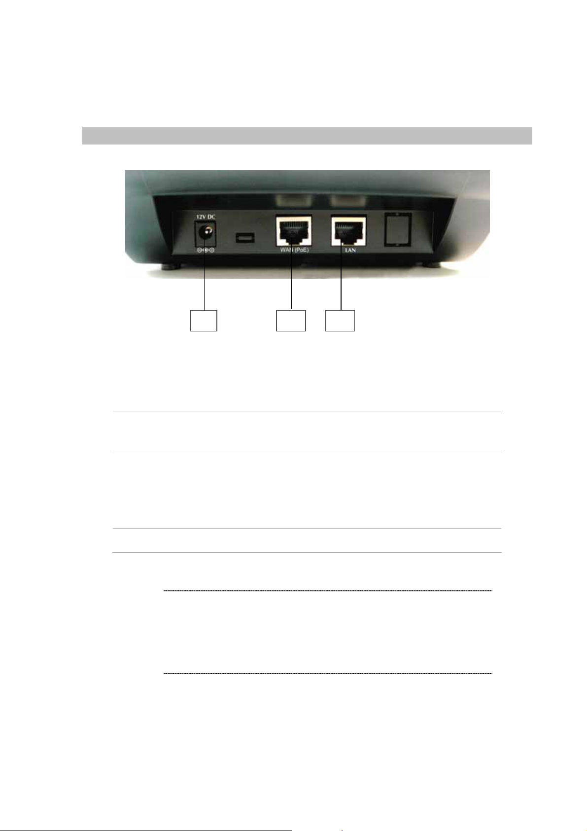
Rear View
Rear Panel of VIP-155PT
L
1 LAN
2 WAN (PoE)
3 12V DC
Hint
RJ-45 connector, to maintain the existing network structure,
connected directly to the PC through straight CAT-5 cable
RJ-45 connector, for Internet access, connected directly to
Switch/Hub through straight CAT-5 cable.
Please connect the WAN interface when using IEEE802.3af
PoE power supply (PT model only)
12V DC Power input outlet
y The Power over Ethernet support on PLANET VIP-155PT
complies with the 802.3af standards. Using non-802.3af
compliant PoE device will burn up the VIP-155PT
permanently.
y Either one power-source is allowed. Please make sure
only one power source is applied to the VIP-155PT.
10
Page 11

2
Chapter 2
Preparations & Installation
Physical Installation Requirement
This chapter illustrates basic installation of VIP-155PT
• Network cables. Use standard 10/100BaseT network (UTP) cables with RJ45 connectors.
• TCP/IP protocol must be installed on all PCs.
For Internet Access, an Internet Access account with an ISP, and either of a DSL or Cable modem (for
WAN port usage)
Administration Interface
PLANET VIP-155PT provides GUI (Web based, Graphical User Interface) for machine management
and administration.
Web configuration access:
To start VIP-155PT web configuration, you must have one of these web browsers installed on
computer for management
• Netscape Communicator 4.03 or higher
• Microsoft Internet Explorer 4.01 or higher with Java support
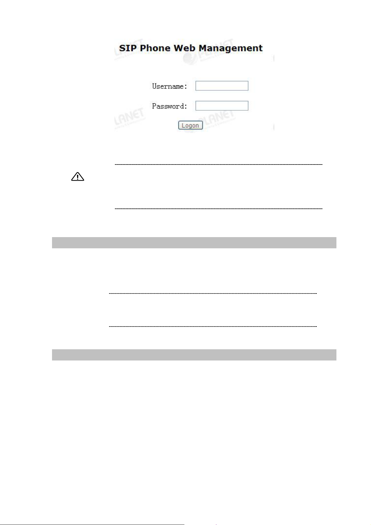
Default LAN interface IP address of VIP-155PT is 192.168.0.1. You may now open your web browser,
and insert 192.168.0.1 in the address bar of your web browser to logon VIP-155PT web configuration
page.
VIP-155PT will prompt for logon username/passwo rd , please enter: rootn / null (no password) to
continue machine administration.
Page 12
Note
Please locate your PC in the same network segment
(192.168.0.x) of VIP-155PT. If you’re not familiar with
TCP/IP, please refer to related chapter on user’s manual
CD or consult your network administrator for proper network
configurations.
LAN/WAN Interface quick configurations
Nature of PLANET VIP-155PT is an IP Sharing (NAT) device, it comes with two default IP addresses,
and default LAN side IP address is “192.168.0.1”, default WAN side IP address is “172.16.0.1”. You
may use any PC to connect to the LAN port of VIP-155PT to start machine administration.
L Hint
In general cases, the LAN IP address is the default gateway
of LAN side workstations for Internet access, and the WAN
IP of VIP-155PT are the IP address for remote calling party
to connect with.
LAN IP address configuration via web configuration interface
Execute your web browser, and insert the IP address (default: 192.168.0.1) of VIP in the adddress bar.
After logging on machine with username/password (default: root / null), browse to “Network” --> “LAN
Config” configuration menu:
12
Page 13
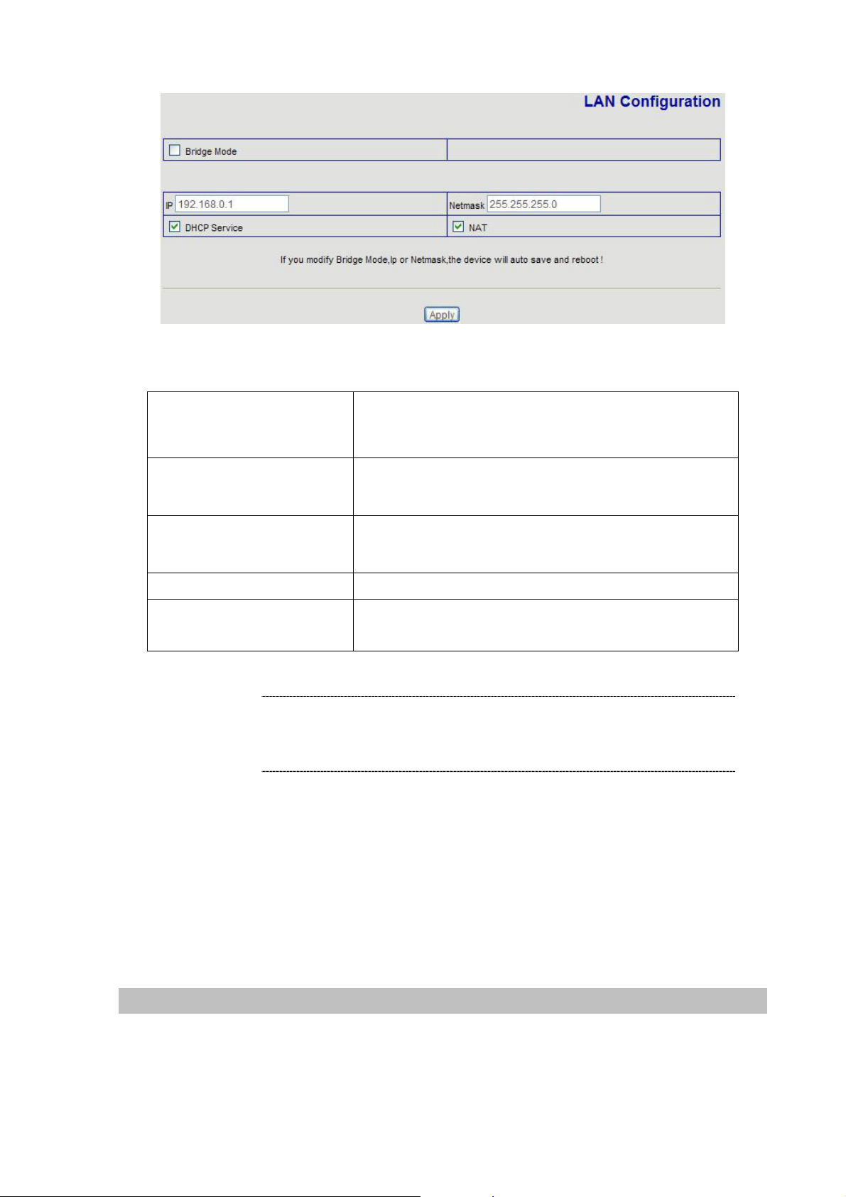
Parameter Description
Bridge Mode
IP address
Subnet Mask
Enable this option to switch to bridge mode. VIP-155PT
won’t assign IP for its LAN port in bridge mode and its LAN
and WAN port will be in the same network.
LAN IP address of VIP-155PT
Default: 192.168.0.1
LAN IP address of VIP-155PT
Default: 255.255.255.0
DHCP Service
NAT
Enable DHCP service in LAN port
Enable NAT function. If Bridge mode is enable, this
function will be disabled.
L Hint
It is suggested to keep the DHCP server related parameters
in default state to keep machine in best performance.
After confirming the modification you’ve done, Please click on the Apply button to macke the changes
effective, browse to “Config Manager” --> “Save Config” configuration menu an d click “Save” button
to save configuration.
Then browse to “System Manage” --> “Reboot” configuration menu and click “Reboot” button to save
configuration.
WAN IP address configuration via web configuration interface
Execute your web browser, and insert the IP address (default: 172.16.0.1) of VIP in the adddress bar.
After logging on machine with username/password (default: root / null), browse to “Network” --> “WAN
Config” configuration menu, you will see the configuration screen below:
13
Page 14
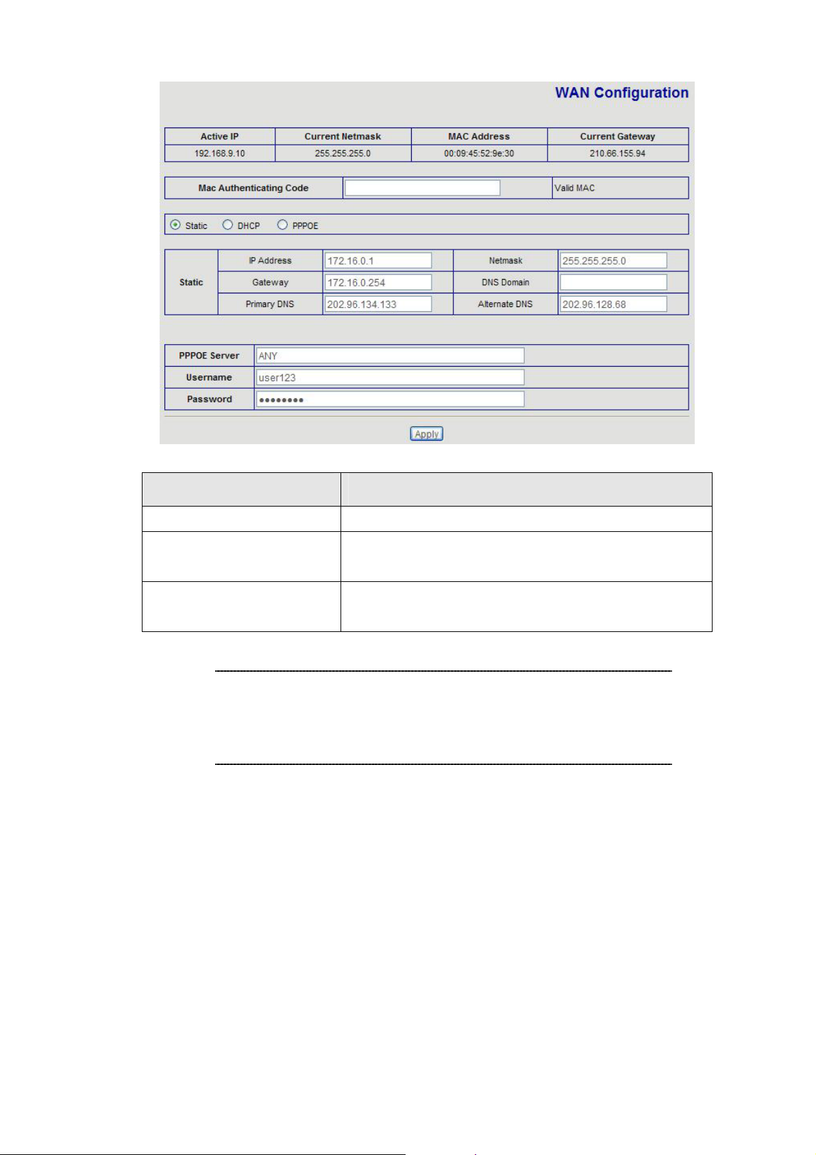
Connection Type Data required.
L
Static IP
DHCP
PPPoE
Hint
The ISP will assign IP Address, and related information.
Get WAN IP Address automatically; it is no need to
configure the DHCP settings.
The ISP will assign PPPoE username / password for
Internet access,
Please consult your ISP personnel to obtain proper PPPoE/IP
address related information, and input carefully.
If Internet connection cannot be established, please check
the physical connection or contact the ISP service staff
for support information.
14
Page 15

3
Chapter 3
Web Configurations
Configuring and monitoring your VIP-155PT from web browser
The VIP-155PT integrates a web-based graphical user interface that can cover most configur ations
and machine status monitoring. Via st andard, web browser, you can configure and check machine
status from anywhere around the world.
Overview on the web interface of VIP-155PT
With web graphical user interface, you may have:
More comprehensive setting feels than traditional command line interface.
Provides user input data fields, check boxes, and for changing machine configuration settings
Displays machine running configuration
To start VIP-155PT web configuration, you must have one of these web browsers install ed on computer
for management
Netscape Communicator 4.03 or higher
Microsoft Internet Explorer 4.01 or higher with Java support
Manipulation of VIP-155PT via web browser
Log on VIP-155PT via web browser
After TCP/IP configurations on your PC, you may now open your web browser, and input
http://192.168.0.1 to logon VoIP gateway web configuration page.
Browse any configuration menu, VIP-155PT will prompt for logon username/password, there are two
level accounts for manage:
Account Name Password Level Description
root
null (no password)
guest
guest
Administrator user, can ma nsge all of
configuration.
General user, just can manage part of
configuration.
15
Page 16
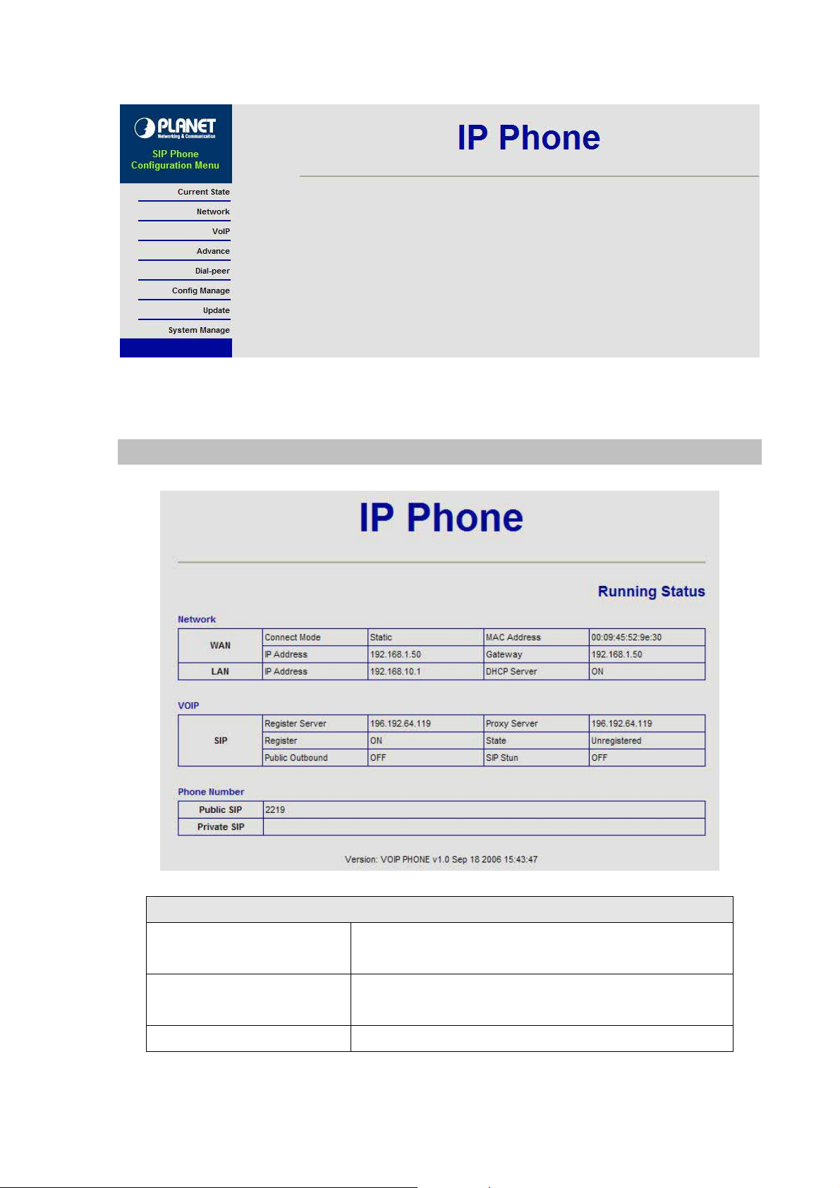
Current State
VIP-155PT main page
Current state information
Network
VOIP
Phone Number
Shows the WAN and LAN port connecting state and
current settings
Part show the working state of VoIP, you can see whether
IP Phone has registered the public sip server
Shows the public sip and private sip phone numbers
16
Page 17
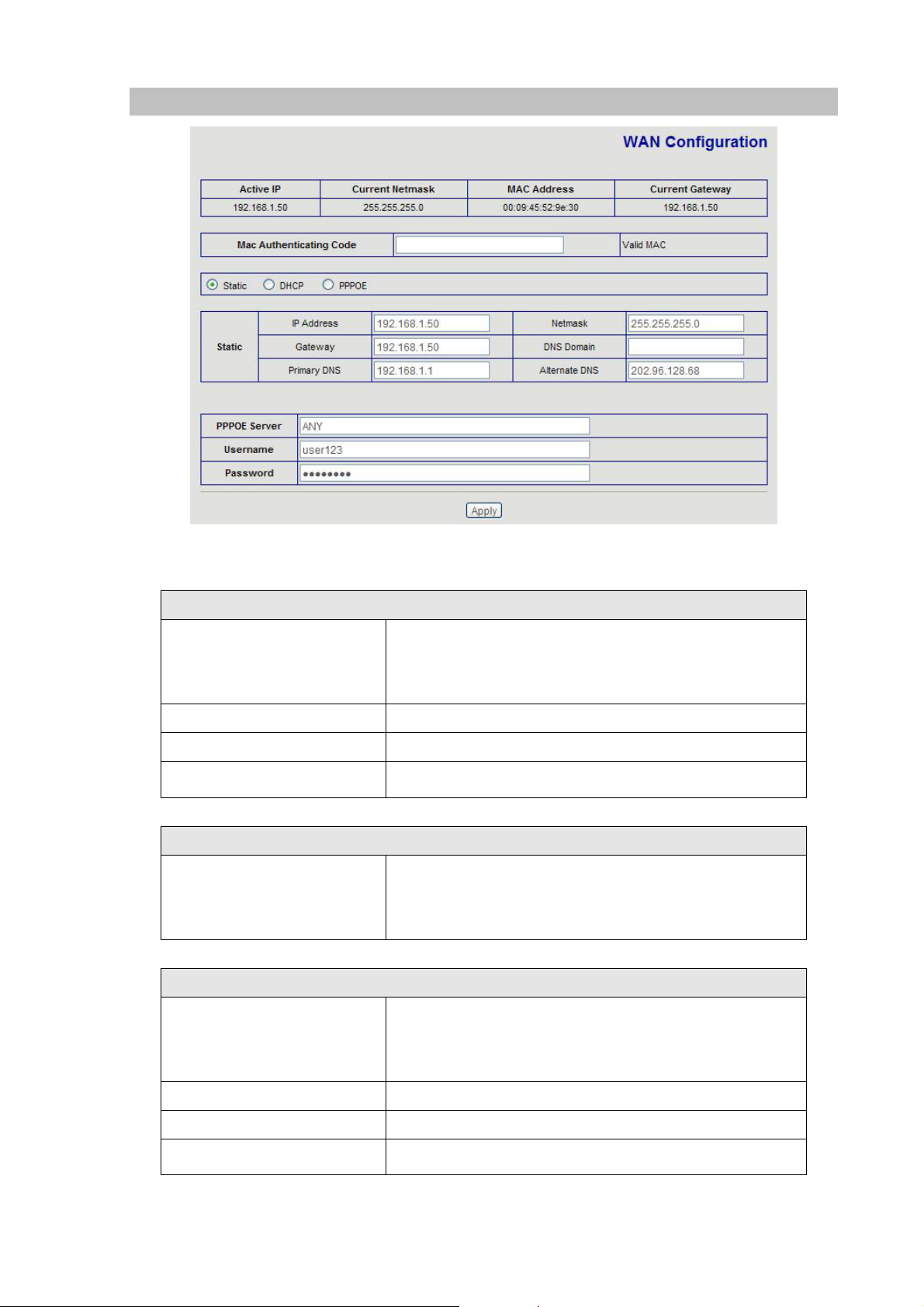
WAN Config:
Three methods are available for Internet Access
Static IP
If you are a leased line user with a fixed IP address, fill out
Fixed IP User
the following items with the information provided by your
ISP.
IP Address
Netmask
Default Gateway
DHCP IP
check with your ISP provider
check with your ISP provider
check with your ISP provider
If there is DHCP server in your local network, VIP-155PT
Dynmaic IP User
will automatically obtain WAN port network information
from your DHCP server.
PPPoE
VIP-155PT will automatically obtain WAN port network
PPPoE User
PPPoE Server
Uasename
Password
information from your ITSP if PPPoE setting and the setup
are correct.
Enter User Name provided by your ISP
Enter Password provided by your ISP
Enter Password to confirm again
17
Page 18
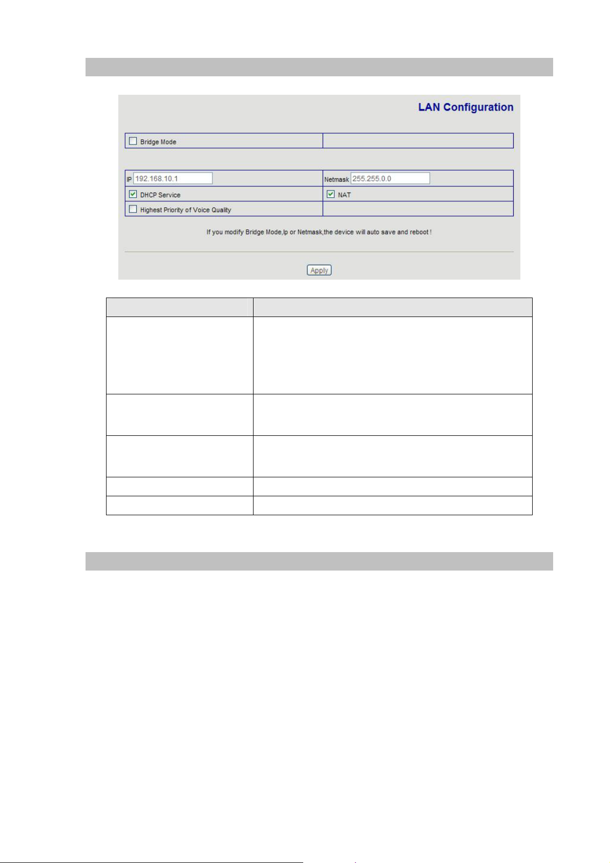
LAN Config
Field Description
Enable this option to switch to bridge mode. IP phone won’t
assign IP for its LAN port in bridge mode and its LAN and
Bridge Mode
WAN port will be in the same network
(This setting won’t take effect unless you save the config
and reboot the device)
IP address
Subnet Mask
DHCP Service
NAT
SIP Config
LAN IP address of VIP-155PT
Default: 192.168.0.1
LAN IP address of VIP-155PT
Default: 255.255.255.0
Enable DHCP service in LAN port
Enable NAT
18
Page 19
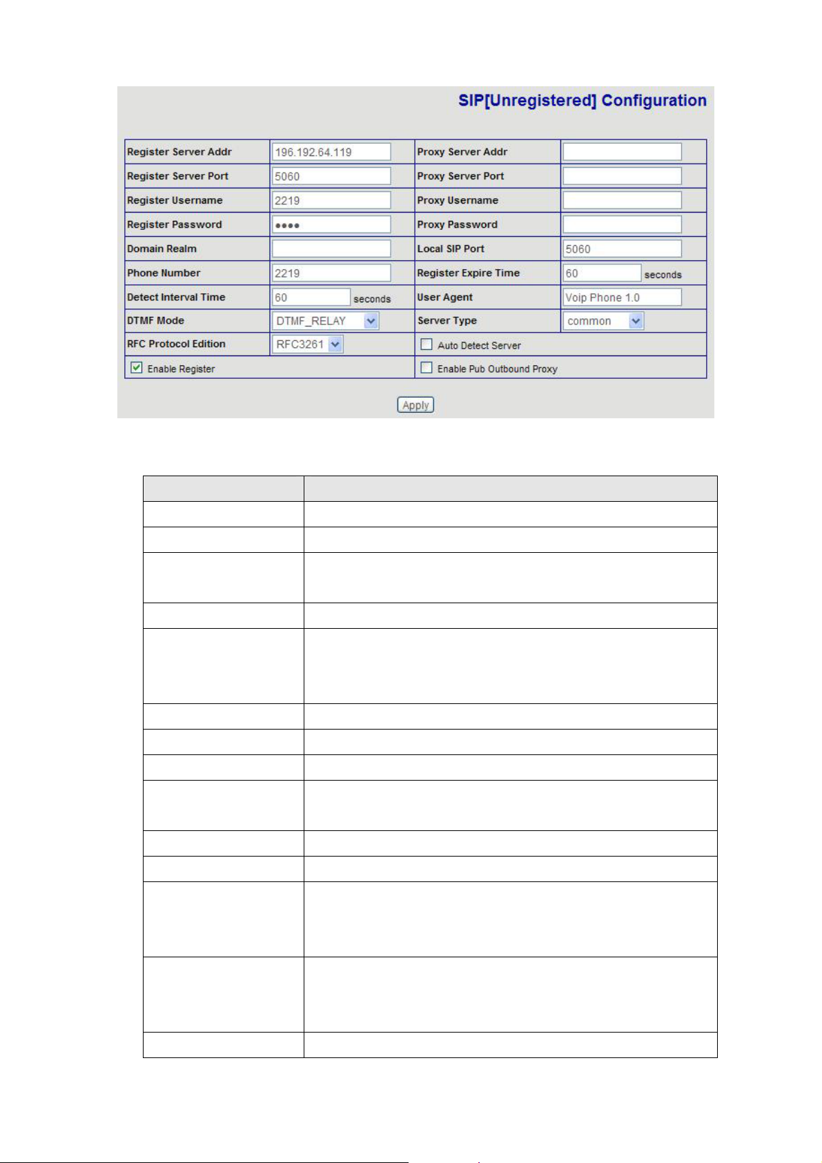
Setting page of public SIP server.
Field Description
Register Server Addr
Register Server Port
Register Username
Register Password
Proxy Server Addr
Proxy Server Port
Proxy Username
Proxy Password
Domain Realm
Local SIP port
Phone Number
Register address of public SIP server
Register port of public SIP server
Username of your SIP account (Always the same as the phone
number)
Password of your SIP account
IP address of proxy SIP server (SIP provider always use the
same IP for register server and proxy server, in this case you
don’t need to configure the proxy server information)
Signal port of SIP proxy
Proxy server username
Proxy server password
SIP domain, enter the sip domain if any, otherwise IP PHONE will
use the proxy server address as sip domain
Local SIP register port, default 5060
Phone number of your SIP account
Register expire time, default is 600 seconds. IP PHONE will auto
Register Expire Time
Detect Interval Time
User Agent
configure this expire time to the server recommended setting if it
is different from the SIP server
Co-work with the Auto Detect Server, if Auto Detect Server is
enable, IP PHONE will periodically detect if the SIP server is
available according this setting
It will show IP Phone’s information on Proxy Server
19
Page 20

DTMF Mode
DTMF signal sending mode: support RFC2833, DTMF_RELAY
(inband audio) and SIP info
Server Type
RFC Protocol Edition
Auto Detect server
Enable Register
Enable Pub Outbound
Proxy
It could support different SIP Proxy providers
Current IP PHONE SIP version. Set to RFC 2543 if the gate n eed
to communicate to devices (such as CISCO5300) using the SIP
1.0. Default is RFC 3261
Co-work with Server Auto Swap and Detect Interval Time. Enable
this option, IP PHONE will periodically detect whether the public
SIP server is available, if the server is unavailable, the IP PHONE
will switch to the back-up SIP sever, and continue detecting the
public sip server. IP PHONE will switch back to the primary SIP
server if the server is available again
Enable/Disable SIP register. IP PHONE won’t sent register info to
SIP server if disable register
Enable/Disable Outbound Proxy
DHCP Server
DHCP server manage page.
User may trace and modify DHCP server information in this page
Field Description
DNS Relay
Lease T able Name
Lease Time
Enable DNS relay function
Lease table name
DHCP server lease time
20
Page 21

Start IP
Start IP of lease table
End IP of lease table. Network device connecting to the IP PHONE
NAT
End IP
Netmask
Gateway
DNS
Notice: This setting won’t take effect unless you save the config and reboot the device
LAN port can dynamic obtain the IP in the range between start IP
and end IP
Netmask of lease table
Default gateway of lease table
Default DNS server of lease table
Advance NAT setting. Maximum 10 items for TCP and UDP port mapping.
Field Description
IPSec ALG
FTP ALG
PPTP ALG
Transfer Type
Enable/Disable IPSec ALG
Enable/Disable FTP ALG
Enable/Disable PPTP ALG
Transfer type using port mappin
21
Page 22

Inside IP
LAN device IP for port mapping
Inside Port
Outside Port
Click Add to add ne w port mapping item and Delete to delete current port mapping item.
LAN device port for port mapping
WAN port for port mapping
Net Service
Field Description
Configure HTTP transfer port, default is 80.User may change this
HTTP Port
Telnet Port
RTP Initial Port
RTP Port Quantity
Notice: Settings in this page won’t take effect unless save and reboot the device.
If you need to change telnet port or HTTP port, please use the port greater than 1024, be cause
ports under 1024 is system remain ports.
HTTP service if HTTP is set to 0.
port to enhance system’s security. When this port is changed,
please use http://xxx.xxx.xxx.xxx:xxxx/ to reconnect.
Configure telnet transfer port, default is 23
RTP initial port
Maximum RTP port quantity, default is 200
Firewall settings
22
Page 23

Firewall setting page. User may set up firewall to prevent unauthorized Internet users from accessing
private networks connected to the Internet (input rule), or prevent unauthorized private network
devices to access the internet.
Access list support two type limits: input_access limit or output_access limit. Each type support 10
items maximum.
IP PHONE firewall filter is base WA N port. So the source address or input destination address should
be WAN port IP address.
Field Description
in_access enable
out_access enable
Input/Output
Deny/Permit
Protocol Type
Port Range
Src Addr
Enable in_access rule
Enable out_access rule
Specify current adding rule is input rule or output rule
Specify current adding rule is deny rule or permit rule
Protocol using in this rule: TCP/IP/ICMP/UDP
Port range if this rule
source address. Can be single IP address or net work address
23
Page 24

Dest Addr
destination address. Can be IP address or network address
Src Mask
source address mask. Indicate the source is dedicate IP if set to
255.255.255.255. Otherwise is network ID
Destination address mask. Indicate the source is dedicate IP if set
Des Mask
to 255.255.255.255. Otherwise is network ID
QoS settings
IP PHONE IP phone implement QoS based on 802.1p, The QoS is used to mark the network
communication priority in the data link/MAC sub-layer. IP Phone will sorted the packets using the QoS
and sends it to the destination.
Field Description
If enable the VLAN service, the second layer will realize separate
voice, signal and data transmission. To realize se parate voice and
VLAN Enable
VLAN ID
DiffServ Enable
DiffServ Value
data transmission by dispose for IP prec edence of ToS area of voice
transmission. To reach upper layer switch or router have priority to
transfer voice transmission. (The prerequisite is the upper layer
swirch or router have to identify ToS area.)
Dispose VLAN ID is add a Tag header after reali ze e nable the VLAN
function. The realized voice packets transfer at the same VLAN. The
prerequisite is it must the same as VLAN of upper switch. The value
range are 1~4094.
If enable the VLAN service, it indicates use DSCP mode to realize
three layers QoS. This moment, the DSCP of SIP signals which
between IP Phone and MGC. It will use Class Selector 5 (The value is
0xA0). And the DSCP of m ediums information (In R TP p acket s) would
be used the values of DiffServ Value field.
The value range are 00 ~ FF. (0x28, 0x30, 0x38, 0x48, 0x50, 0x58,
0x68, 0x70, 0x78, 0x88, 0x90, 0x98, 0xb8)
Advance SIP settings
24
Page 25

This page is used to set the private sip server, stun server, and back up sip server information .
STUN Server setting:
Field Description
STUN Server Addr
STUN Server Port
STUN Effect Time
Enable SIP STUN
Configure stun server address
Configure stun server port default 3478
Stun detect NAT type circle, unit: minute
Enable/disable stun
Public Alter Register:
Public Alter server provide redundancy for the public server, if the public server is unavailable, IP
PHONE will use the alter server , and switch ba ck to the public se rver when it i s available. Account
setting in public alter setting should be the same as the public server.
Please refer to
SIP_Config for the setting for how to set the public alter server.
25
Page 26

User can register two sip servers:
Public sip server and private sip server.these two sip servers are independent from each other
and running in the same time.
For how to configure private sip server. Please refer to
Digital Map
SIP_Config
Digit map is a set of rules to determine when the user has finished dialing.
IP Phone support below digital map:
Digital Map is based on some rules to judge when user end their dialing and send the number to the
26
Page 27

server.
VIP-155PT support following digital map:
Field Description
End With “#”
Fixed Length
Timeout
User Define digital map:
Field Description
[ ]
x
Tn
Example:
Represents the range of digit, can be a range such a s [1-4], or u se comm a such
as [1,3,5], or use a list such as [234]
Represents any one digit between 0~9
Represents the last digit timeout. n represents the time from 0~9 second, it is
necessary. Tn must be the last two digit in the entry . If Tn is not included in the
entry, we use T0 as default, it means system will sent the number immediately if
the number matches the entry.
Use # as the end of dialing
When the length of the dialing match, the call will be sent
Specify the timeout of the last dial digit. The call will be sent after
timeout
Field Description
[1-8]xxx
9xxxxxxx
911
99xT4
All number from 1000 to 89999 will be sent immediately
8 digits numbers begin with 9 will be sent immediately
Number 911 will be sent will be immediately
3 digits numbers begin with 99 with be sent after four seconds
Call Service Settings
27
Page 28

User configure the value add service such as hotline, call forward, call transfer, 3-way conference
call .etc in this page
Field Description
Hotline
Call Forward
No Disturb
Configure hotline number. IP PHONE immediately dials this
number after hook-off if it is set
Forward when busy: select Busy in the Call Forward Field, and
Key in the destination phone number in the Forward Number. If
some one calls you when you having a call, the caller will be
forwarded to the destination number.
Forward no answer: Select No Answer in the Call Forward Field,
and Key in the destination phone number in the Forward Number,
fill the time in the No Answer Time. If some one calls you and no
one answer the caller during the No Answer Time, the call will be
forward to the destination number.
Forward Always: Select Always in the Call Forward Field, and
Key in the destination phone number in the Forward Number,
then any one call this gateway will be forward to the destination
number.
DND, do not disturb, enable this option to refuse any calls
28
Page 29

Ban Outgoing
Enable this to ban outgoing calls
Check the Enable Call Transfer.
Unattended transfer: If A is the IP PHONE user, and B calls and
talking with A through VoIP. A can press FWD button to hold the
call with B, and then enter C’s number. B will be transferred to C
Enable Call Transfer
Enable Call Waiting
Enable Three Way
Call
Accept Any Call
Auto Answer
Enable Voice Record
and can talk with C.
Attended transfer: If A is the IP PHONE user, and B calls and
talking with A through VoIP. A can press Hold button to hold the
call with B, and then enter C’s number to talk will C. and press
Hold to switch back to A, and then press FWD key , B will be
transferred to C and can talk with C.
Enable/disable Call Waiting
Check Enable Three Way Call
Assume A is the VIP-155PT user, and B calls and talking with A
through VoIP. A can press FWD button to hold the call with B,
then enter * and then enter C’s number to t alk with C, and then
press * button again to make 3-way conference calls.
If this option is disable, IP PHONE refuse the incoming call when
the called number is different from IP PHONE’s phone number.
Enable/disable auto answer function
Enable/disable answering machine function. Please refer to the
bwloe descriptions for detail.
User-defined Voice
Incoming Record
Playing
No Answer Time
Black List
Limit List
Use customized greeting message
Simultaneously play the message when recording
No answer call forward time setting
Incoming call in these phone numbers will be refused
Outgoing calls with these phone numbers will be refused
Voice Record
VIP-155PT provides record function. With this function, user may record three VoIP message and one
local message.
Field Description
Select “Enable Voice Record” to active answering
machine, and config No Answer Time. If there is an
Enable Voice Record
incoming call and no one answer the call. After timeout, IP
PHONE will auto answer this call and ask the caller to leave
message.
29
Page 30

Incoming Record Playing
Play the message when recording
User-Defined Voice
Record local message:
User may use local message to leave message to other local users.
Please refer the Record button function as below:
Level1 Level2 Description
Received
User define
New New message info
Old Old message info
Record Enable/disable answering machine
Playing Enable/disable Incoming Record Playing
Play Play local message Local
Rec Record local message
Switch Enable/disable customize greeting message
Play Play customize greeting message
Use customizes greeting voice for answering machine
Record Function
Rec Record customize greeting message
MMI Filter
MMI filter is used to make access limit to IP PHONE IP phone.
When MMI filter is enable. Only IP address within the start IP and end IP can access IP PHONE IP
phone.
Audio Settings
30
Page 31

Field Description
CODEC
Signal Standard
Input Volume
Output Volume
Handfree Volume
Handdown Time
G729 Payload Length
VAD
Dial-Peer Settings
select the prefer CODEC; support ulaw, alaw,G729 and G7231
5.3/6.3
Signal standard for different area
Handset in volume
Handset out volume
Hand free volume
hand down detect time
G729 payload length
Enable/disable Voice Activity Detection
VIP-155PT provide flexible dial rule, with different dial-rule configure, user can easily implement the
following function:
----Replace, delete or add prefix of the dial number .
31
Page 32

----Make direct IP to IP call
----Place the call to different servers according the prefix.
You can click “Add” to add a new dial rule. Below is the detail setting of the dial-rule:
Field Description
The Number suit for this dial rule, can be set as full match or prefix
match. Full match means that if the number user dialed is completely
the same as this number, the call will use this dial-rule. Prefix match
Phone Number
Destination
(optional)
Port (optional)
Alias (optional)
means that if prefix of the number that the user dials is the same as
the prefix, the call will use this dial-rule, to distinguish from the full
match case, you need to add “T” after the prefix number in the phone
number setting
call destination, can be IP or domain. Default is 0.0.0.0, in this case
the call will be routed to the Public SIP server. If you set the
destination to 255.255.255.255, then the call will be routed to the
private SIP server. Also you can key other address here to make
direct IP calls
Configure the port of the destination, default is 5060 in SIP and 1720
for H323
Set up the Alias. We support four Alias as below. Alias need to
co-work with the Del Length:
¾ add:xxx, add prefix to the phone number, can set to reduce the dial
length.
¾ all: xxx, replace the phone number with the xxx, can use as speed
dial function.
¾ del, delete the first N numbers. N is set in the Del Length
Suffix (optional)
Example:
rep:xxx,replace the first N numbers. N is set in the Del Length. For
Example: Use wants to place a call 8610-62281493, then you can set
the phone number in the dial rule as 010T, and set the Alias as
rep:8610, and set the Del Length to 3. Then all calls begin with 010
will be changed to 8610 xxxxxxxx.
Configure suffix, show no suffix if not set
32
Page 33

Field Description
2T rule
If the call starts with 2, the first 2 will be deleted, and the rest number will be
sent to private SIP server.
If the call starts with 3, the first 3 will be deleted, and the rest number with be
3T rule
sent to public SIP server.
Dial 123 and will send 8675583018049 to your server. Used as speed dial
123 rule
function
If the calls is begin with 0, the first 0 will be replace by 86. Means that if you
0T rule
dial 075583018049 and AG-188 will send 8675583018049 to your server.
When you dial 179 , the call with send to 192.168.1.179, suit for LAN
179 rule
application without set up a sip server.
Config Manage
Field Description
Save Config Save current settings
Clear Config Restore to default settings
Notice: clear config in admin mode, all settings restores to factory default; clear config in guest
modem, all settings except sip and advance sip restore to factory default.
WEB Update
Update IP phone’s settings or firmware. Firmware file is .z extension when co nfigure file is .cfg
extension, IP PHONE will auto select configure update or firmware update according the extension.
33
Page 34

FTP/TFTP Update
Backup:
Back up configure file to your FTP/TFTP server.
* configure use .cfg extension.
Auto update:
IP PHONE IP phone support FTP and TFTP auto update. The gateway will auto obt ain the configure file
from your update server if configured. To obtain the original configure file, you can use the FTP/TFTP
back up as describe above. Configure file using module structure, user may remain the concerned
modules and remove other modules. Put the configure file in the root directory of update serve when
finish editing.
34
Page 35

Configure file version was in the <<VOIP CONFIG FILE>> and <GLOBLE CONFIG MODULE>
ConfFile Version
Example:
Gateway original version is:
<<VOIP CONFIG FILE>>Version:1.0000
<GLOBLE CONFIG MODULE> ConfFile Version:6
User may edit the configure file version to:
<<VOIP CONFIG FILE>>Version:1.0007
<GLOBLE CONFIG MODULE> ConfFile Version:7
Account Manage
Set web access account or keypad password of IP PHONE.
35
Page 36

Phone Book
User may set contacts in this page, and the conta cts will be saved in the memory. Then using the
Pbook, Vol+,Vol-,Menu/OK and Exit keys to choose your friend in the contacts and then press # to call
out.
Syslog Config
Field Description
Enable Syslog
Server IP
Server Port
Enable syslog function.
VIP-155PT will automatic send the system logs to define server. Fill in
the server IP address.
Fill in the transmission port.
Time Set
VIP-155PT could support SNTP timeset, type in SNTP Server add ress, Timezone and timeout fileds.
And click “select sntp” to enable SNTP function.
If hasn’t click “select sntp”, it also could set up time by manual.
36
Page 37

Reboot
Reboot IP phone, some setting needs to reboot to make it works. Please always save config before
reboot, otherwise the setting will return to previous setting.
37
Page 38

Chapter 4
Keypad Configurations
Keypad Function
User can configure IP PHONE through its keypad. List below is the keypad function
Keypad Mode Function/Display
Idle mode ---- show current time
Sysinfo Idle mode circularly show phone number,wan ip, gateway info
Idle mode enter config mode, default password 123 Menu/OK
4
config mode confirm or enter sub-menu
Exit config mode exit
Calling mode volume up (Max:9) Up
config mode Page up
Calling mode volume down (Min:1) Down
config mode Page down
Calling mode Delete digits Del
config mode Delete digits
Mute Calling mode Mute
Out call Idle mode Outgoing call menu
In call Idle mode Incoming call menu
Record Idle mode Enter record menu, usage refer FAQ
Pbook Idle mode Enter Phone book set up
Handfree Calling mode Handfree
0-9
Calling mode Digits 0~9
config mode Hit quickly to switch between numeric or alphabetic
Calling mode Use in 3-way conference call.*
config mode Use as “.” In the ip address setting
38
Page 39

# Calling mode Use as end key of dialing or the dial number
Hold Calling mode Hold, detail refer value add service
FWD Calling mode Transfer, detail refer value add service
Redial Calling mode Redial key
Send Calling mode call key
No.1~No.9 Idle mode Speed dial key
Keypad Menu
User may use SET, Menu/ok, Exit, Vol+, Vol- to config IP PHONE detail setting. Press Menu/ok to
enter config mode, and the default password is 123.
Below list the keypad menu of IP PHONE
IP PHONE Keypad Menu
Level 1 Level 2 Level 3 Level 4
Network
LAN
WAN
IP
Netmask
DHCP Server
NAT
Bridge Mode
Status
Static Net
Switch
FTPalg
IPSec alg
PPTPalg
1. IP
2. NetMask
3. Gateway
4. DNS
5. DNS2
User name PPPoE
Password
Call Feature
Limit-List
Black-List
QoS
Public SIP Phone-number
Private SIP
Current
ADD
DEL
Current
ADD
39
Page 40

FastCall
Three Call
Call-Transfer
Call-Waiting
DEL
SIP
Call-Forward
Dial-Rule
Condition
SIP
End With #
Fixed Length
Public Reg Reg Status
Private Reg
Public Reg Switch
Private
Public Domain
Private
Public User Agent
Transfer Num
Transfer IP
Port
Switch
Length
Register Server Private
Proxy
DSP
Detect-server
Dtmf-mode
Interval-time
Swap-server
RFC-version
Signal-Port
Stun
Codec
Handdown-time
Dtmf-Volume
Input-volume
Output-Volume
Private
Switch
Addr
Port
Effect Time
Save System
Reboot
40
Page 41

Set Default
Other Setting Syslog
Switch
Server-IP
Server-Port
41
Page 42

5
Chapter 5
Telnet Console
Introduce
Basic Structure
User may use telnet command to access and manage IP phone.
IP PHONE adopts tree structure for telnet. Every node contains its sub-nodes or local command. User
can type “help” or “?” whenever to see sub-nodes and all local command under current node.
Besides local command, there are some global commands can be used in each node.
Basic command
Logout: exit telnet mode.
Write: save current settings.
Type sub-nodes name in current node to switch to sub-node.
Type “!” or “exit” in current node to return to parent-node.
Type “help” or “?” can see all sub-nodes and all local command under current node,
every help item has comments such as <command> or <node> to distinguish
sub-nodes and local command. Type “help” or “?” in command can see all parameters
using in this command.
When typing node name or command, user no need to key the full name, use TAB
button will make it more efficient.
There are two types in command parameters: optional and required. “required”
parameter use “-” as prefix and “optional” use “_” as prefix. User may type “-” or “_”
then press TAB button for complementarily.
42
Page 43

Global Command
Global command is available under all nodes, IP PHONE support following commands:
Command Function Example
chinese Set to Chinese UI #chinese
clear Clear telnet screen #clear
english Set to English UI #english
exit Return to parent-node #exit
help
history Show command history #history
logout Exit #logout
ping Ping command, use to check network, #ping www .google.com
tree Print tree structure of current command #tree
who Show current user #who
write Save setting to flash #write
1. Show help info
2. Show sub-nodes and local command
1.#help ping
2.#help
Tree Structure
account
path: <account>#
[stop]start Syslog ---syslog [no] start
Configure Syslog server address and port ---syslog server –ip x.x.x.x _port xxx
Example: #<config-account-syslog>#server ---ip 202.112.20.10
Show syslog settings ---syslog show
Show all account settings ---show
config
¾ accesslist firewall config
path: <config-accesslist>#
add firewall rule ---entry –I/O xxx –P/D xxx –proto xxx –srcaddr
x.x.x.x –srcmask x.x.x.x–desaddr x.x.x.x –desmask x.x.x.x –portrange xxx –portnum xxx
Example:<config-accesslist>#entry –I/O input –P/D deny –proto udp –straddr 202.112.10.1 –srcmask
255.255.255.0 –desaddr 210.25.132.1 –desmask 255.255.255.0 –portrange neq –portnum 5060
43
Page 44

delete firewall rule ---no entry –I/O xxx –index xxx
Example :<config-accesslist>#no entry –I/O input –index 1
Show firewall settings ---show
[disable] enable input filter ---[no]in-access
[disable] enable output filter ---[no]out-access
¾ DHCP
path: <config-dhcp>#
add DHCP rule ---entry –name xxx –startip x.x.x.x –endip
x.x.x.x –netmask x.x.x.x –gateway x.x.x.x –dnsserver x.x.x.x _time xxx
Example:<config-dhcp>#entry –name lan2004 –st artip 192.168.1.2 –endip 192.168.1.254 –netmask
255.255.255.0 –gateway 192.168.1.1 –dnsserver 192.168.10.18
delete DHCP rule ---no entry –name xxx
Example: <config-dhcp>#no entry –name lan2004
Show DHCP settings ---show
[disable]enable DNS-relay ---[no]dns-relay
¾ dialrule
path: <config-dialrule>#
[disable] enable End with # ---[no]endchar
Set end with fix length ---fixlen xxx
Disable end with fix length ---no fixlen
Set timeout to send ---timeout-send xxx
Disable timeout to send ---no timeout-send
Add digital map ---entry –prefix xxx –length xxx
Example: <config-dialrule>#entry –prefix 010 –length 11
Delete digital map rule ---no entry –prefix xxx
Example: <config-dialrule>#no entry –prefix 010
Show current digital map ---show
¾ LAN interface settings
path: <config-interface-fastethernet-lan>#
[disable]enable bridge mode ---[no]bridgemode
[disable]enable DHCP service ---[no]dhcp-server
[disable]enable NAT ---[no]nat
Show current DHCP rules ---dhcpshow
44
Page 45

Show LAN port IP address ---ipshow
Show NAT info ---natshow
Change LAN port IP address ---ip –addr x.x.x.x –mask x.x.x.x
Example:<config-interface-fastethernet-lan>#ip –addr 192.168.1.10 –mask 255.255.255.0
¾ WAN interface settings
path: <config-interface-fastethernet-wan>#
[disable]enable dhcp client ---[no]dhcp
[disable]enable pppoe ---[no]pppoe
[disable]enable QOS ---[no]qos
Set default gateway IP ---gateway x.x.x.x
Clear default gateway IP ---no gateway
Set WAN port IP address ---ip –address x.x.x.x -mask x.x.x.x
Example:<config-interface-fastethernet-wan>#ip –addr 202.112.241.100 –mask 255.255.255.0
You need to reconnect if the WAN port has been changed.
Show WAN port settings ---show
¾ MMI Filter
path: <config-mmifilter>#
add filter rule ---entry –start x.x.x.x –end x.x.x.x
Example:<config-mmifilter>#entry –start 202.112.20.1 –end 202.112.20.255
Delete filter rule ---no entry –start x.x.x.x
Example:<config-mmifilter>#no entry –start 202.112.20.1
Show filter rule ---show
[disable]enable MMI filter ---[no]start-filter
¾ NAT settings
path: <config-nat>#
[disable]enable ftp alg ---[no]ftpalg
[disable]enable ipsec alg ---[no]ipsecalg
[disable]enable pptp alg ---[no]pptpalg
Add TCP mapping rule ---tcp-entry –ip x.x.x.x –lanport xxx –wanport xxx
45
Page 46

Example:<config-nat>#tcp-entry –ip 192.168.1.5 –lanport 1720 –wanport 1000
Delete TCP mapping rule ---no entry –ip x.x.x.x –lanport xxx –wanport xxx
Example:<config-nat>#no tcp-entry –ip 192.168.1.5 –lanport 5060 –wa nport 1000
Add UDP mapping rule ---udp-entry –ip x.x.x.x –lanport xxx –wanport xxx
Delete UDP mapping rule ---no udp-entry –ip x.x.x.x –lanport xxx –wanport xxx
Show NAT info ---show
¾ Netservice
path: <config-netservice>#
Set DNS address ---dns -ip x.x.x.x _domain xxx
Example:<config-netservice>#dns –ip 202.112.10.36 _domain voip.com
Set alternate DNS address ---alterdns -ip x.x.x.x _domain xxx
Set hostname ---hostname xxx
Set http access port ---http-port xxx
Show http access setting ---http-port
Set telnet access port ---telnet-port xxx
Show telnet access port ---telnet-port
Set RTP initial port and quantity ---media-port –startport xxx –number xxxx
Example:<config-netservice>#media-port –startport 10000 –number 200
Add route rule ---route –gateway x.x.x.x –addr x.x.x.x –mask x.x.x.x
Example:Arcihfone<config-netservice>#route –gateway 202.112.10.1 –addr 202.112.210.1 –mask
255.255.255.0
Delete route rule ---no route –gateway x.x.x.x –addr x.x.x.x –mask x.x.x.x
Show route info ---route
Show netservice info ---show
¾ Dial-peer settings
path: <config-pbook>#
[disable]enable calling through GK and proxy ---[no]enableGKandProxy
Add number-IP bond entry ---entry –number xxx –ip x.x.x.x –protocol xxx
Example:<config-pbook>#entry –number 100 –ip 202.112.20.100 –protocol sip
Add number-IP bond and add prefix to the dial number
46
Page 47

---entry –number xxx –ip x.x.x.x –protocol xxx _add xxx
Example:<config-pbook>#entry –number 100 –ip 202.112.20.100 –protocol sip _add 123(dial 100 and
will send 123100 according this rule)
Add number-IP bond and replace the destination with another number
---entry –number xxx –ip x.x.x.x –protocol xxx _all xxx
Example:<config-pbook>#entry –number 100 –ip 202.112.20.100 –protocol sip _all 123( user dial 100
and gateway will sent 100 instead)
Add number-IP bond and delete the prefix of the destination number
---entry –number xxx –ip x.x.x.x –protocol xxx _del xxx
Example:<config-pbook>#entry –number 1234 –ip 202.112.20.100 –protocol sip _del 2 (dial 1234 will
send 34 instead)
Add number-IP bond and replace the prefix with another number
---entry –number xxx –ip x.x.x.x –protocol xxx _rep xxx _length xxx
Example:<config-pbook>#entry –number 1234 –ip 202.112.20.100 –protocol sip _rep 567 _length
2(dial 1234 will send 56734)
Delete dial-peer entry ---no entry –number xxx
Show current dial-peer rules ---show
Set default voip protocol ---default-protocol xxx
¾ Port settings
path: <config-port># 或<config-port X>#
set accecp relay mode ---accept-relay xxx
set callerid mode ---callerid xxx
disable callerid ---no callerid
config call forward ---callforward –conditon xxx –number xxx –ip xxx –port xxx –protocol xxx
Example:<config-port 0>#callforward –condition busy –number 100 –ip 202.112.10.100 -port
5060 –protocol sip
Disable call forward ---no callforward
[disable]enable call transfer ---[no]calltransfer
[disable]enable call waiting ---[no]callwaiting
47
Page 48

Set prefer codec ---codec xxx
Set DTMF gain ---dtmfvolume xxx
Set black list ---in-limit xxx
Show black list ---in-limit
Set input volume ---input xxx
Set outgoing limit list ---out-limit xxx
Show outgoing limit list ---out-limit
Set output volume ---output xxx
[disable]enable outgoing limit ---[no]shutdown out
[disable]enable black list ---[no]shutdown in
[disable]enable outgoing limit and black list ---[no]shutdown
[disable]enable 3-way conference ---[no]threetalk
Show port settings ---show
¾ PPPoE settings
path: <config-pppoe>#
PPPoE account settings ---auth –user xxx -password xxx
Example:<config-pppoe>#auth –user aaa –pas sword 123456
[disable]enable service settings ---[no]service xxx
Show pppoe settings ---show
¾ QOS settings
path: <config-qos>#
[delete]add QoS table entry --- [no]entry –addr x.x.x.x –mask x.x.x.x
Example:<config-qos>#entry –addr 202.112.10.1 –mask 255.255.255.0
[disable]enable include QOS table ---[no]include
Show QoS settings ---show
¾ SIP settings
path: <config-sip>#
[disable]enable registration ---[no] register
[disable]enable auto detect server ---[no] detect-server
Set sip domain ---default-domain xxx
Set DTMF mode ---dtmf-mode xxx
Set auto detect interval time ---interval-time xxx
Set RFC edition ---rfc-version xxx
[disable]enable auto swap server --- [no]swap-server
Set sip account ---number-password –number xxx –password xxx
48
Page 49

Set local SIP signal port --- signalport xxx
Set proxy server ---server proxy -ip x.x.x.x _port xxx _user xxx _password xxx
Example:<config-sip-server># proxy ip 210.25.23.22 _port 5060 _user aaa _password 123456
Set register server info ---server register -ip x.x.x.x _port xxx –user xxx
_password xxx
Set alter proxy info ---alter-server proxy –ip x.x.x.x _port xxx _user xxx
_password xxx
Set alter server info ---alter-server register –ip x.x.x.x _port xxx _user xxx
_password xxx
[disable]enable stun server ---stun [no]enable
Set stun detecting interval time ---stun interval-time xxx
Set stun server ip and port ---stun –ip x.x.x.x –port xxx
Show current sip info ---show
¾ User management
path: <config-user>#
Change user right. ---access –user xxx –access xxx
Example:<config-user>#access –user aaa –access 7
Change user password ---password –user xxx
Add new user ---entry –user xxx –access xxx
Example:<config-user>#entry –user abc –access 7
Delete user entry ---no entry –user xxx
Show current sip info ---show
Debug (Level 0~7)
path: <debug>#
show debug setting ---show
[disable]enable debug all modules ---[no] all xxx
[disable]enable debug app module ---[no] app xxx
[disable]enable debug cdr module ---[no] cdr xxx
[disable]enable debug sip module ---[no] sip xxx
[disable]enable debug h323 module ---[no] h323 xxx
[disable]enable debug tel module ---[no] tel xxx
[disable]enable debug dsp module ---[no] dsp xxx
49
Page 50

Download configure to flash
usage: #download tftp –ip x.x.x.x –file xxx
#download ftp –user xxx –password xxx –ip x.x.x.x –file xxx
Example: #download ftp –user abc –p assword 123 –ip 202.112.20.15 –file AG188.cfg
Password
usage: #password
Enter new password:xxx
Confirm new password:xxx
Reload
usage: #reload
Reboot system
Show system running info
¾ accesslist
path: <show>#
show: accesslist (firewall) settings
Example: #<show>#accesslist
¾ basic
path: <show>#
show network status
Example: #<show>#basic
¾ call
path: <show>#
show current call info
Example: #<show>#call active
¾ capability
path: <show>#
show CODEC capability
Example: #<show>#capability
¾ debugging
50
Page 51

path: <show>#
show debug info
Example:#<show>#debugging
¾ dhcp-server
path: <show>#
show LAN status and DHCP server info
Example:#<show># dhcp-server
¾ dial-rule
path: <show>#
show digital-map info
Example:#<show># dial-rule
¾ interface
path: <show>#
show LAN info
Example:#<show>#interface fastethernet lan
show WAN info
Example:#<show>#interface fastethernet wan
¾ ip
path: <show>#
show arp table info
Example:#<show>#ip arp
Show DNS server info
Example:#<show>#ip dns
Show netstate info
Example:#<show>#ip netstat
Show route info
Example:#<show>#ip route
Show icmp packets Stat.
Example:#<show>#ip icmp
Show igmp packets Stat.
Example:#<show>#ip igmp
51
Page 52

Show ip packets Stat.
Example:#<show>#ip ip
Show RTP packets Stat.
Example:#<show>#ip rtp
Show TCP packets Stat.
Example:#<show>#ip tcp
Show UDP packets Stat.
Example:#<show>#ip udp
¾ memory
path: <show>#
show IP phone memory
Example:#<show>#memory
¾ nat
path: <show>#
show NAT information
Example:#<show>#nat
¾ port
path: <show>#
show caller-ID info
Example:#<show>#port callerID
show dsp info
Example:#<show>#port dsp
show hotline info
Example:#<show>#port hotline
show black list info
Example:#<show>#port in-limit
show outgoing limit info
Example:#<show>#port out-limit
52
Page 53

show current phone number
Example:#<show>#port number
show current port status
Example:#<show>#port status
¾ PPPoE
path: <show>#
show PPPoE info
Example:#<show># pppoe
¾ qos
path: <show>#
show QoS table info
Example:#<show>#qos
¾ sip
path: <show>#
show sip info
Example:#<show>#sip
¾ udptunnel
path: <show>#
show UDP tunnel info
Example:#<show># udptunnel
¾ uptime
path: <show>#
show running time
Example:#<show># uptime
¾ version
path: <show>#
show IP phone version
Example:#<show># version
Telnet and logout
Usage: #telnet –target -port
Login:xxx
53
Page 54

Password:xxx
#
#logout
Telnet and logout
path: <time>#
---manualset –year xxx –month xxx –day xxx –hour xxx –minute xxx –second xxx
Example:<time>#manulset –year 2004 –month 10 –day 1 –hour 8 –minitute 30 –second 0
[disable]enable SNTP server ---sntp [no] start
Set SNTP IP address ---sntp server x.x.x.x
Set SNTP server timeout ---sntp timeout xxx
Set timezone (-12~+12) ---sntp zone xxx
Show SNTP info ---sntp show
Show current time ---print
Tracert trace network path info
usage: #tracert –host
Example:#tracert
3
HYPERLINK "http://www.google.com"
45
www.google.com
Update IP Phone
usage: # update ftp –user xxx –password xxx –ip x.x.x.x –file xxx
# update tftp –ip x.x.x.x –file xxx
Example:# update ftp –user abc –password 123 –ip 202.112.20.15 –file AG188.dlf
Upload configure file
usage: # upload ftp –user xxx –password xxx –ip x.x.x.x –file xxx
# upload tftp –ip x.x.x.x –file xxx
Network Diagnosis
There are some telnet commands for checking your network. Now Listing below for your information
Command Function Example
54
Page 55

ping Check if the destination is accessible #ping www . google.com
tracert Show network path info #tracert www.google.com
show basic Show network settings #show basic
show ip route Show route table #show ip route
show ip arp Show arp table #show ip arp
show ip netstat Netstat programe #show ip netstat
telnet Telnet to another device #telnet 192.168.1.2
Reset to factory default
#setdefault clear IP phone settings expect network part
#setdefault all clear all settings.
POTS Mode (Safe mode)
VIP-155PT provide safe mode. When there is booting problem because of setting problem or firmware
problem. User can restore the factory setting or upgrade to a new firmware to solve this problem .
How to enter safe mode?
There will be a schedule bar in the VIP-155PT booting procedu re, press # key within the first 5 seco nds,
then the phone will go to POST mode. It has a default ip 192.168.10.1 in POST mode. User may
change the PC’s IP address to 192.168.10.xx and telnet to 192.168.10.1 to access the VIP-155PT in
POST mode.
User can accord the guide in post mode to clear the settings or upgrade the firmware.
55
Page 56

Appendix A
FAQ
Q1: How many servers may VIP-155PT register simultaneously?
A1: VIP-155PT is able to register two SIP servers simultaneously, and redundancy servers.
User can configure the dial peer to route calls between these servers.
Q2: Why the settings vanish after reboot?
A2: Please go to Config ManageÆSave Config to save your setting always.
Q3: How to use speed dial function?
A3: There are 9 speed dial keys in the IP PHONE p anel, Usage:
Set speed dial number: press the speed key and enter the speed dial number and then press
Menu/OK key to save the setting.
Pick up the handset and press the speed dial key to dial the pre-define number.
Q4: How to use set the IP type via keypad?
A4: In the idle mode, user may us the keypad to set the IP type as the below procedure:
Keep pressing the button 1 for changing to static mode.
Keep pressing the button 2 for changing to DHCP mode.
Keep pressing the button 3 for changing to PPPoE mode.
56
Page 57

Appendix B
Voice communications
There are several ways to make calls to desired destination in IP Phone. In this section, we’ll lead you
step by step to establish your first voice communication via keypad and web browsers opera t ions.
Peer to Peer (P2P) Mode
Step 1: Assuming there are two VIP-155PT in the network the IP address are 172.16.0.1 and
172.16.0.2
Step 2: Execute your web browser, and insert the IP address (172.16.0.1) of the VIP-155PT-A in the
adddress bar . After log on machine, browse to “Dial-peer” configuration item:
VIP-155PT-A
WAN IP Address
(172.16.0.1)
VIP-155T-B
WAN IP Address
(172.16.0.2)
Step 3: Press “Add” button and fill in the below parameter, be sure to click the “Submit” button to apply
settings. Browsing to “Config Manage” Æ “Save Config” configuration item and press “Save” button to
save the configuration.
57
Page 58

Step 4: Pick up handset or press “Handfree” key from keypad of VIP-155PT-A and dial “2#”. Then the
phone of VIP-155PT-B sho uld ring. You can do the same thing to the VIP-155PT-B.
L
Hint
Proxy Mode
VIP-155PT-A
WAN IP Address
(172.16.0.1)
y If the IP address of the remote calling party is known,
you may directly make calls by preset number via its
IP address and end with an “#”.
y If the IP phones are installed behind a NAT/firewall/
IP sharing device, please make sure the NAT device
support SIP applications before making calls
Number: 100 Number: 200
VIP-155T-B
WAN IP Address
(172.16.0.2)
SIP-50
WAN IP Address
(172.16.0.10)
SETP 1:
58
Page 59

Please browse machine “VoIP” Æ “SIP Config” menu, and enable the “Enable Register”
check box. Insert IP address of the remote calling party in the “Register Server Addr” field.
Sample configuration screen is shown below:
SETP 2:
After these configurations, be sure to click the “Apply” button to apply settings.
Browsing to “Dial-peer” configuration item, press “Add” button and fill in the below
parameter.
After these configurations, be sure to click the “Apply” button to apply settings.
59
Page 60

SETP 3:
Browsing to “Config Manage” Æ “Save Config” configuration item and press “Save” button
to save the configuration. Browsing to “System Manage” Æ “Reboot” menu and press
“Reboot” button reboot the machine to make the settings effective. After rebooting, the unit
will register to SIP-50, the LCD screen will show below:
SETP 4:
VOIP PHONE
SEP 20 13 12:30
At this moment, you may pick up the handset and dial “200” to connect with extension 200 of
VIP-155PT-B to start the voice communications.
60
Page 61

Appendix C
VIP-155PT series Specifications
Product Power over Ethernet SIP IP Phone
Model VIP-155PT
Hardware
WAN 1 x 10/100Mbps RJ-45 port
Power Over Ethernet 802.3af compliant at PT model
LAN 1 x 10/100Mbps RJ-45 port
LCD display 2 x 16 characters
Speaker 8 Ohm/0.2 Watt speaker for speakerphone operation
Protocols and Standard
Standard SIP 2.0 (RFC3261), SIP digest authentication (MD5)
Voice codec G.723.1 (6.3k/5.3k), G.729, G.711 (a-law/u-law)
NAT Traversal Outbound Proxy, STUN
Voice Standard Voice activity detection (VAD)
Comfort noise generation (CNG)
Dynamic Jitter Buffer
Supplementary services Immediate (unconditional) call forwarding
Busy call forwarding
No answer calls forwarding
Calls hold/transferring.
Answer Machine
3-Way conference calls
Call history Incoming call
Outgoing call
Missed (not accepted) call history
Voice Record
Protocols TCP/IP, UDP/RTP/RTCP, HTTP, ICMP, ARP, DNS, DHCP, NTP/SNTP, FTP,
PPP, PPPoE
Network and Configuration
Access Mode Static IP, PPPoE, DHCP
Management Web, Keypad, Telnet
Dimension (W x D x H) 200 mm x 184 mm x 60 mm
Operating Environment 0~40 degree C, 10~90% humidity
Power Requirement 12V DC
(802.3af 48VDC in line power)
EMC/EMI CE, FCC Class B
61
 Loading...