

Page 1
16-port + 2 Gigabit-slots VDSL Stackable Switch
VC-1602
User’s Manual
Page 2

Trademarks
Copyright PLANET Technology Corp. 2003.
Contents subject to revision without prior notice.
PLANET is a registered trademark of PLANET Technology Corp. All other trademarks belong
to their respective owners.
Disclaimer
PLANET Technology does not warrant that the hardware will work properly in all environments
and applications, and makes no warranty and representation, either implied or expressed, with
respect to the quality, performance, merchantability, or fitness for a particular purpose.
PLANET has made every effort to ensure that this User’s Manual is accurate; PLANET
disclaims liability for any inaccuracies or omissions that may have occurred.
Information in this User’s Manual is subject to change without notice and does not represent a
commitment on the part of PLANET. PLANET assumes no responsibility for any inaccuracies
that may be contained in this User’s Manual. PLANET makes no commitment to update or keep
current the information in this User’s Manual, and reserves the right to make improvements to
this User’s Manual and/or to the products described in this User’s Manual, at any time without
notice.
If you find information in this manual that is incorrect, misleading, or incomplete, we would
appreciate your comments and suggestions.
FCC Warning
This equipment has been tested and found to comply with the limits for a Class A digital device,
pursuant to Part 15 of the FCC Rules. These limits are designed to provide reasonable
protection against harmful interference when the equipment is operated in a commercial
environment. This equipment generates, uses, and can radiate radio frequency energy and, if
not installed and used in accordance with the Instruction manual, may cause harmful
interference to radio communications. Operation of this equipment in a residential area is likely
to cause harmful interference in which case the user will be required to correct the interference
at his own expense.
CE Mark Warning
This is a Class A product. In a domestic environment, this product may cause radio interference,
in which case the user may be required to take adequate measures.
Revision
PLANET 16-port + 2 Gigabit-slots VDSL Stackable Switch User's Manual
FOR MODELS: VC-1602
Part No.: EM-VC1602
Page 3

TABLE OF CONTENTS
CHAPTER 1 INTRODUCTION..................................................................................................1
1.1 CHECKLIST.........................................................................................................................1
1.2 ABOUT THE SWITCH............................................................................................................1
1.3 FEATURES..........................................................................................................................2
1.4 SPECIFICATIONS.................................................................................................................2
CHAPTER 2 HARDWARE INSTALLATION.............................................................................4
2.1 FRONT PANEL.....................................................................................................................4
2.2 REAR PANEL ......................................................................................................................7
2.3 HARDWARE INSTALLATION...................................................................................................8
2.4 STACK INSTALLATION........................................................................................................10
CHAPTER 3 CONSOLE AND TELNET MANAGEMENT.......................................................11
3.1 CONNECT TO PC BY RS-232 SERIAL CABLE......................................................................11
3.2 TELNET ............................................................................................................................11
3.3 MAIN MENU......................................................................................................................12
CHAPTER 4. WEB MANAGEMENT.......................................................................................15
4.1 START A WEB BROWSER SESSION....................................................................................15
4.2 STACK MAIN PAGE............................................................................................................16
4.3 SWITCH MAIN PAGE..........................................................................................................17
4.4 DEVICE CONFIGURATION...................................................................................................20
4.5 TOPOLOGY INFO...............................................................................................................21
4.6 PORTS .............................................................................................................................21
4.7 SECURITY.........................................................................................................................26
4.8 SNMP.............................................................................................................................26
4.9 VLAN..............................................................................................................................28
4.10 ADDRESS TABLE.............................................................................................................31
4.11 MIRROR .........................................................................................................................32
4.12 IGMP SNOOPING ...........................................................................................................32
4.13 PRIORITY........................................................................................................................32
CHAPTER 5. TROUBESHOOTING........................................................................................34
APPENDIX A...........................................................................................................................35
A.1 SWITCH‘S RJ-45 PIN ASSIGNMENTS..................................................................................35
A.2 10/100MBPS, 10/100BASE-TX........................................................................................35
A.3 RJ-45 CABLE PIN ASSIGNMENT..........................................................................................36
A.4 RJ-21 CONNECTOR PIN OUT.............................................................................................36
Page 4

Chapter 1 INTRODUCTION
1.1 Checklist
Check the contents of your package for following parts:
l VC-1602.
l CD-ROM.
l Quick Installation Guide
l Power cord.
l 19” rack-mount brackets.
l RS-232 cable.
If any of these pieces are missing or damaged, please contact your dealer immediately, if
possible, retain the carton including the original packing material, and use them against to
repack the product in case there is a need to return it to us for repair.
1.2 About the Switch
The VC-1602 is an Ethernet over VDSL switch with sixteen VDSL ports (on 1 RJ-21
connector) and two Gigabit slide-in slots on the rear panel for optional fiber/copper Gigabit
modules. The switch is a DSLAM (Digital Subscriber Line Access Multiplexer)
accommodating well proven Ethernet and VDSL technologies to extend Ethernet over
single-pair phone line by using a VDSL signal. Up to 15/17Mbps bandwidth and 5
selective transmission modes provides ultra-high performance to the pervasive telephone
line network, and has the advantage of minimum installation time and minimum expense
by allowing voice and data to share the same telephone pair without interference.
Moreover, the maximum 1.5km distance provides wide coverage for service providers.
The 2 Gigabit slide-in slots on the rear panel provide fat pipes for connecting to the
backbone or connecting to servers. 10/100/1000Base-T, 1000Base-SX and 1000Base-LX
modules are available to fit existing networks and to provide flexible media selections.
The VDSL Switch contains an advanced management capability that can be remotely
accessed by Telnet, SNMP and Browser. The standard IEEE 802.1Q with VLAN tagging
feature makes logically separating nodes easier with up to 255 VLAN groups allowed.
Two priority queues with 802.1p support, IGMP snooping and rate control function are
also provided to optimize network bandwidth.
The VC-1602 provides switch stacking functionality to manage up to 8 switches using a
single IP address. Through its proprietary management bus using a standard RJ-45
cable, the distance between stacked switches can be up to 800m. The management bus
traffic is separated from the network ports, ensuring heavy network loading does not affect
management tasks. 128 VDSL ports can be managed with a single IP address.
The VC-1602 is ideal for providing broadband services to subscribers in apartment, hotel
and campus communities. Fully compatible with Cisco LRE CPE modems, PLANET's
VDSL solution provides a lower cost replacement and smooth migration from existing
Cisco LRE networks.
- 1 -
Page 5

1.3 Features
w Cisco LRE CPE modem compatible
w Complies with IEEE802.3 10Base-T, IEEE802.3u 100Base-TX, IEEE 802.3z
1000Base-SX/LX, IEEE 802.3ab 1000Base-T, IEEE 802.3x flow control, IEEE 802.1Q
VLAN and 802.1p priority queuing
w 5 selectable transmission modes using the management interface of the VC-1602
w QAM ( Quadrature Amplitude Modulation) line code
w Designed based on Frequency Division Duplexing
w A telco-50 (RJ-21) connector for VDSL ports
w Voice and data communication can be shared on the existing telephone wire
simultaneously
w Provides 6k MAC address table and 384K bytes memory buffer
w Supports 802.1p QoS with two priority queues
w Supports 802.1Q tagged VLAN, up to 255 VLAN groups can be configured
w Console, telnet, web and SNMP manageable
w Supports IGMP snooping
w Port mirroring for dedicated port monitoring
w Rate control function to limit bandwidth to 10%, 20% to 100%.
1.4 Specifications
Product 16-port + 2 Gigabit-slots VDSL Stackable Switch
Model VC-1602
Network Ports Telco-50 (RJ-21), provides 16 VDSL connections
Stack Ports 2 x RJ-45
Module slot 2 for 10/100/1000Base-T, 1000Base-SX and 1000Base-LX modules
Console 1 x RS-232 DB-9
Stack ID selection Knob with 8 settings (0~7)
MAC address table size 6k
Transmission method Store-and-forward
Packet Buffer Memory 384K Bytes
LEDs System: PWR, Master, Status
Per port: LNK, ACT
Port Module: LNK/ACT
Stack: LNK
Cables 10Base-T: 2-pair UTP Cat. 3,4,5 up to 100m
100Base-TX: 2-pair UTP Cat.5, up to 100m
1000Base-T: 4-pair UTP Cat 5, up to 100m
1000Base-SX: 50/125 and 62.5/125 fiber-optic cable, up to 550m
1000Base-LX: 9/125 fiber optic cable, up to 10km
50/125 and 62.5/125 fiber-optic cable, up to 550m
VDSL: twisted-pair telephone or ISDN wires (AWG24 or better) up to
5000ft (1.5km)
Mode/Distance
(Based on AWG24
wires)
Rack Mount 19” rack mount, 1U height
Dimension 440 x 285 x 44 mm
Operating Environment Temperature: 0~50 degree C (operating), -20~70 degree C (storage)
Power Supply 100~240VAC, 50~60Hz, auto-sensing
ANSI - 15/4Mbps asymmetrical rate up to 4100 feet (1.25km)
ETSI - 11/4Mbps asymmetrical rate up to 4100 feet (1.25km)
VE-5 - 5/5 Mbps symmetrical rate up to 5000 feet (1.5km)
VE-10 - 11/11Mbps symmetrical rate up to 4100 feet (1.25km)
VE-15 - 15/17Mbps asymmetrical rate up to 3500 feet (1.05km)
Humidity: 0~90%, non-condensing
- 2 -
Page 6

EMC/EMI FCC, CE
Management Interface Web, Console, Telnet and SNMP
Protocols and Standards IEEE 802.3 (Ethernet)
IEEE 802.3u (Fast Ethernet)
IEEE 802.3z/802.3ab (Gigabit Ethernet)
IEEE 802.3x (flow control)
IEEE 802.1Q VLAN tag
IEEE 802.1p QoS
RFC 768 UDP
RFC 783 TFTP
RFC 791 IP
RFC 792 ICMP
RFC 826 ARP
RFC 854 Telnet
RFC 2068 HTTP
RFC 2236 IGMPv2
Network Management RFC 1157 SNMP v1/v2
RFC 1123 MIB-2
RFC 1493 Bridge MIB
- 3 -
Page 7
Chapter 2 HARDWARE INSTALLATION
This section describes the hardware features and installation of these Switches. For
easier management and control of the switch, familiarize yourself with its display
indicators, and ports. Front panel illustrations in this chapter display the unit LED
indicators. Before connecting any network device to the switch, read this chapter
carefully.
Furthermore, there are three choices of different modules for expansion:
l WGSW-D1GT: 10/100/1000Base-T module
l WGSW-D1SX: 1000Base-SX module
l WGSW-D1LX: 1000Base-LX module
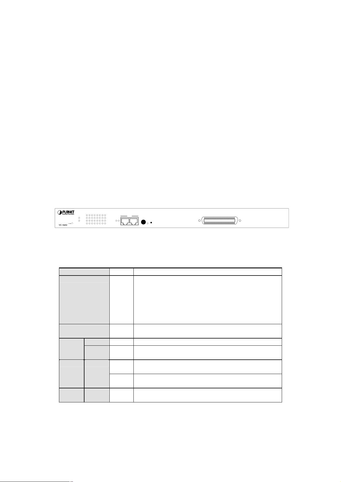
2.1 Front Panel
The unit front panel provides a simple interface monitoring the switch.
910111213141516
LNK
ACT
MASTER
STATUS
LNK
PWR
ACT
12345678
1718
LNK/ACT
STACK
INOUT
Switch ID
RESET
LNK
VDSL
VC-1602 Switch front panel
16-port VDSL Stackable Switch
LED indicators
PWR Green On: Power on
MASTER Green When this LED steady green, it means the device acts
competent leading role(Master), an indispensable essential for
system administrator to control and monitor whole system.
At the time one member of the cluster disconnected or new
member joined, the LED blinks. Soon, one and only one master
will be raised. You can refer to “SWITCH ID” for relative
information.
STATUS Flashing
Green
LNK Green Well connected with CPE device VDSL
ACT Flashing
Green
Module LNK/ACT
Green When one slide-in module is well installed and functioning, the
Flashing
Green
STACK LNK Green On: The switch is stacked to others
Run Time Error occurs
There is traffic transverses the port
relevant one lights green
There is traffic transverses the port
Off: The switch is standalone or the stack link have problem
- 4 -
Page 8

load rate is about 9% less than the line rate due to framing
AWG 26 (0.4mm) cable can also be used but the distance is 20% to 40%
Each terminated bridge tap can reduce the VDSL link distance by 90m.
cable, the size of the cable bundles, and the cross talk
Stack ports
There are two stack ports on the front panel. One is IN and the other is OUT. When
stacked, the IN port should connect to the other switch’s OUT port and the OUT port
should connect to other switch’s IN out. You can just use normal Cat 5 or better cable with
RJ-45 connector to stack. Only straight-through UTP/STP cable can be used. There is no
Duplex Mode issue and the maximum distance between first and last switch is 800m.
SWITCH ID
Each switch on a stack must have a unique switch ID. There are eight degrees (0~7) in
the rotary switch. The switch with least switch ID will become master switch and the
others become slave. If master switch is fail or disconnected to the switch by stack port,
the switch with least switch ID will become master.
Every device in the management stack should have a unique “Switch ID”. In the
meanwhile, a “Switch ID” which has been using by a device, reused by another, the
management stack will fail.
Reset button
At the middle of front panel, the reset button is designed for reboot the switch without turn
off and on the power.
VDSL ports
There are 16 VDSL ports within 1 RJ-21 connector on the front panel.
The VDSL supports 5 selective transmission modes that operate in different band
allocation and result in different upstream and downstream bandwidth. Due to different
telephone line quality, cross talk or extension distance may affect actual achievable
speed; you can configure individual port in built-in management interface for optimized
connectivity.
The following is the summary table of transmission modes, bandwidth and distance
extensibility tested for AWG 24 (0.5mm) twisted-pair without noise and cross talk.
Profile Name Profile Type Downstream
Rate (Mbps)
ANSI Public 15.17 4.27 4100 ft (1.25km)
ETSI Public 11.38 4.27 4100 ft (1.25km)
VE-5 Private 5.69 5.69 5000 ft (1.5km)
VE-10 (default) Private 11.38 11.38 4100 ft (1.25km)
VE-15 Private 15.17 17.06 3500 ft (1.05km)
ëNote
1. The pay
overhead.
2.
shorter than above table.
Upstream
Rate (Mbps)
Maximum Distance between
the CO Port and the CPE
3.
The quality of the
within the bundle, can also affect other overall reach.
- 5 -
Page 9
products are designed to share lines with analog,
N), and digital private branch
700 kHz frequency
range. Digital telephones connected to digital PBX switches that use
frequencies above 700 kHz do not work when sharing a line with LRE
proprietary nature of digital PBX switches, some digital
PBX switch services use frequencies above 700 kHz. Besides, digital
telephones connected to digital PBX switches that use frequencies above
Wiring for VDSL ports
The VDSL port of VC-1602 uses one RJ-21 (Telco 50) connector to connect up to 16
VDSL converters (VC-102S, VC-101S or Cisco LRE modem) through structured or
unstructured wiring, such as existing telephone lines. The link between the VDSL switch
port and each converter can reach speeds of up to 15/17 Mbps over distances of up to
5000 feet (1500 meters). You can hot swap the VDSL converters without powering down
the switch or disrupting the other switch ports.
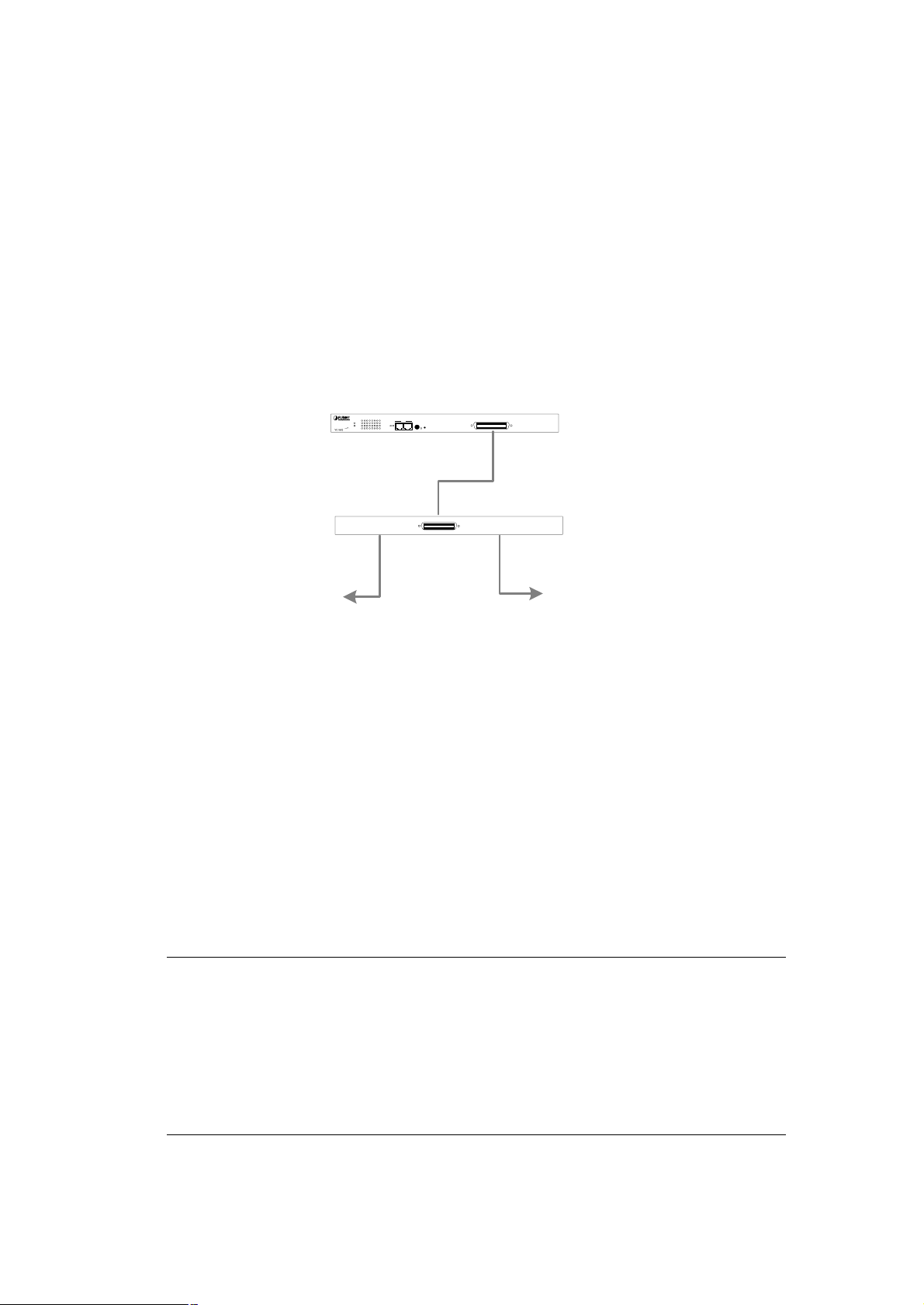
If telephone services, such as voice or an Integrated Services Digital Network (ISDN), use
the same cabling as VDSL traffic, the VDSL port must be connected to the patch panel
through a plain old telephone service (POTS) splitter. The splitter routes VDSL data
(high-frequency) and voice (low-frequency) traffic from the telephone line to the switch
and private branch exchange (PBX) switch or public switched telephone network (PSTN).
The connection diagram is as the following.
To PBX /
PSTN
910111213141516
LNK
ACT
LNK
ACT
12345678
STACK
Switch ID
1718
RESET
LNK/ACT
LNK
INOUT
DSLAM
DSLAM
MASTER
STATUS
PWR
VD-CO16P
PBX
16-port VDSL Stackable Switch
VDSL
LINE
VC-1602
VDSL Splitter
To VDSL
Converter
If the port is connected but the relevant LED is dark, check the following items:
1. The switch and the connected device’s power are on or not.
2. The connecting cable is good and with correct type.
3. The cable is firmly seated in its connectors in the switch and in the associated
device.
4. The connecting device, including any network adapter is well installed and
functioning.
5. Confirm the CPE device is implemented within the scope of operative without
interference.
For more information about the splitter, please consult your local dealer about the splitter and
refer the user’s guide of the splitter.
PLANET VC-1602
Integrated Services Digital Network (ISD
ëNote
exchange (PBX) switch telephones that use the 0 to
signals. Due to the
700 kHz will not work when sharing a line with LRE signals.
- 6 -
Page 10
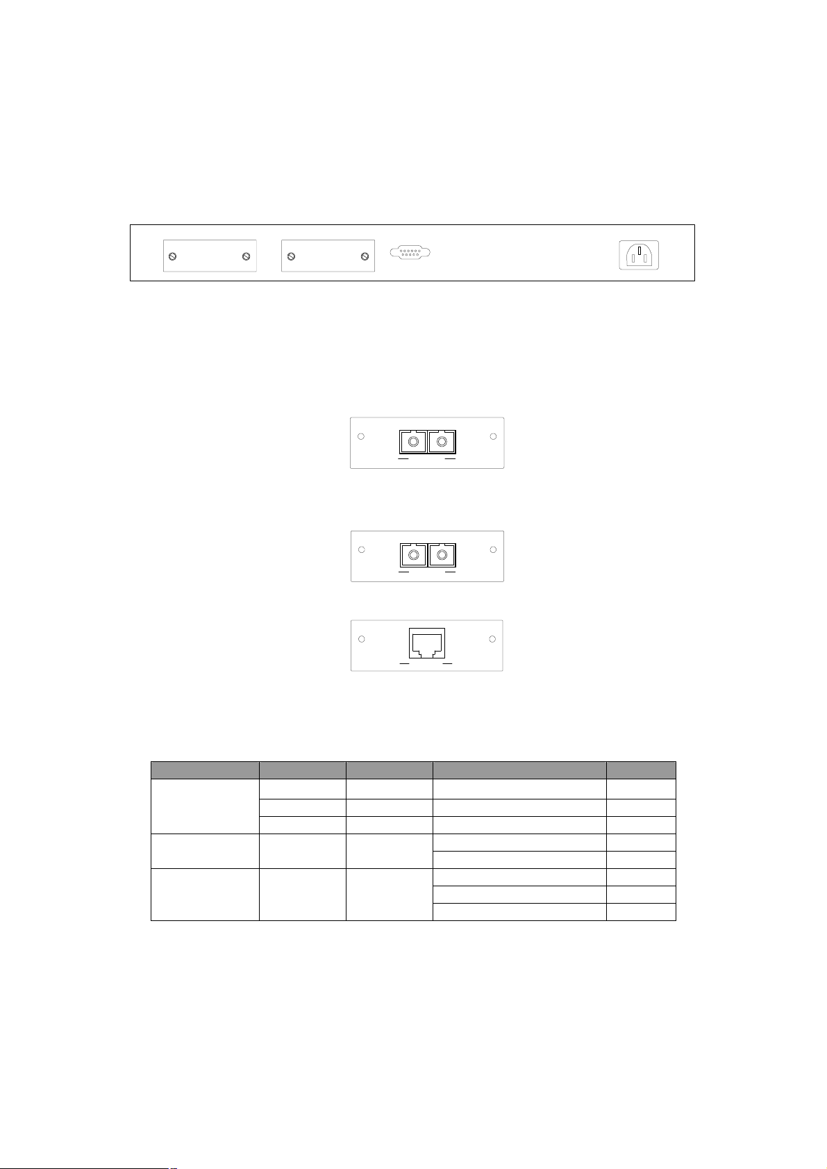
2.2 Rear Panel
The rear panel of the switch indicates an AC inlet power socket, which accepts input
power from 100 to 240VAC, 50-60Hz, one RS-232 console port for setting up the switch
via a connection to a terminal or PC using a terminal emulation program, and two slide-in
slots for installing additional modules.
1718
CONSOLE
9600, 8, N, 1
100~240VAC
50/60Hz
VC-1602 Switch front panel
Slide-in slots
The two slide-in slots on the rear panel are reserved for following optional gigabit
modules. They can provide fat pipes for up linking to backbone or connecting to servers.
WGSW-D1SX
1000BASE-SX : WGSW-D1SX
WGSW-D1LX
1000BASE-LX : WGSW-D1LX
WGSW-D1GT
TXRX
1000Base-SX
TXRX
1000Base-LX
1000Base-T
1000BASE-T : WGSW-D1GT
The following is the gigabit module operation and cabling required:
Media Speed Duplex Mode Wiring Distance
1000BASE-T
10Mbps Full / Half Category 3,4,5 UTP/STP
100m
100Mbps Full / Half Category 5 UTP/STP 100m
1000Mbps Full Category 5 UTP/STP 100m
62.5/125 µm MMF 220m 1000BASE-SX 1000Mbps Full
50/125 µm MMF 500m
1000BASE-LX 1000Mbps Full
62.5/125 µm MMF 550m
50/125 µm MMF 550m
9/125 µm SMF 10km
Console Port
The RS-232 console is an interface for connecting a terminal directly. Through the
console port, it provides rich diagnostic information includes network statistics, link status
and system setting. The operating mode of the console port is:
- 7 -
Page 11

♦ DCE
♦ 9600 (Fix baud rate)
♦ n (No parity checking)
♦ 8 (8 Data bits)
♦ 1 (1 stop bit)
♦ None (No flow control)
You can use a normal RS-232 cable and connect to the console port on the device. After
the connection, you can run any terminal emulation program (Hyper Terminal, Winterm,
Telix, and so on) to enter the startup screen of the device.
Power Receptacle
For compatibility with electric service in most areas of the world, the switch’s power supply
automatically adjusts to line power in the range 100-240 VAC and 50/60 Hz.
Plug the female end of the power cord firmly into the receptacle on the rear panel of the
switch. Plug the other end of the power cord into an electric service outlet then the power
will be ready.
Power Notice:
1. The device is a power-required device, it means, it will not work till it is powered. If your
networks should active all the time, please consider using UPS (Uninterrupted Power
Supply) for your device. It will prevent you from network data loss or network downtime.
2. In some area, installing a surge suppression device may also help to protect your switch
from being damaged by unregulated surge or current to the Switch or the power
adapter.
2.3 Hardware Installation
This switch can be placed directly on your desktop, or mounted in a rack. If you install the
device in a normal-standalone standard, the switch is an managed Switch, and users can
immediately use most of the features simply by attaching the cables and turning the
power on. In this case, any managerial proceedings are effective only in the range of the
switch. After management stacking, you can enjoy the powerful management functions
and control the whole system.
Desktop Installation
For desktop installation, the switch needs to put on a clean, flat desk or table close to a
power outlet. Plug in all network cables and the power cord, then the system is ready.
Before installing the switch, you must ensure:
1. It is accessible and cables can be connected easily.
2. Cabling is away from:
w Sources of electrical noise such as radios, transmitters and broadband amplifiers
w Power lines and fluorescent lighting fixtures.
3. Keep water or moisture off.
4. Airflow around the unit and through the vents in the side of the case is great for heat
radiation (company recommend that you provide a minimum of 25 mm clearance).
To prolong the operational life of your units:
- 8 -
Page 12

in slots are not hot swappable, power off the switch before
1. Never stack unit more than eight sets high if freestanding.
2. Do not place objects on top of any unit or stack.
3. Do not obstruct any vents at the sides of the case.
Rack-mount Installation
The switch may standalone, or may be mounted in a standard 19-inch equipment rack.
Rack mounting produces an orderly installation when you have a number of related
network devices. The switch is supplied with rack mounting brackets and screws. These
are used for rack mounting the unit.
Rack Mounting the Switch in the 19-inch rack:
1. Disconnect all cables from the switch before continuing.
2. Place the unit the right way up on a hard, flat surface with the front facing toward
you.
3. Locate a mounting bracket over the mounting holes on one side of the unit.
4. Insert the screws and fully tighten with a suitable screwdriver.
5. Repeat the two previous steps for the other side of the unit.
6. Insert the unit into the 19" rack and secure with suitable screws (not provided).
7. Reconnect all cables.
Installing Network Cables
Station Connections -
Refer to the wiring statement of the previous section; connect each station with correct
type of cables.
Switch-to-Switch Connections –
In making a switch-to-switch connection, use Gigabit ports to connect another switch or
backbone is strongly recommended. The Gigabit ports provide the fat pipe to the server or
backbone connectivity for boosting the total system performance. Refer to the wiring
statement of the previous section; connect each station to the switch with correct type of
cables.
Module Installation
The two slide-in slots on the rear panel are purposed for installing optional modules. They
can be used as a network backbone or connect to a server. Follow the steps as described
to install a module:
1. Power off the switch.
2. Removing the two screws on the face plate of slide-in slot with a flat-head
screwdriver.
3. Push the module gently into the slot along the slide tracks.
4. Ensuring that it firmly engages with the connector then tighten the screws to secure
the module.
ëNote
The slide-
installing modules.
- 9 -
Page 13

device uses a unique
“SWITCH ID”, or the management stack will not work. The switch with
least SWITCH ID will become Master. Only Master switch’s management
2.4 Stack Installation
There are two RJ-45 ports on the front panel for proprietary management stack. Only
straight-through UTP/STP cable can be used.
Plug one end of the cable in the “IN” port and the other end to the ”OUT” port of next
device. Repeat the step for every device in the stack cluster, then ending at last switch.
Before management stacking, be sure of every
ëNote
interface (console, telnet, web and SNMP) is accessible.
Please find the following picture for sample connection. Please note the stack port is for
management only. For data packets to be transmitted between switches, you will still
need to connect their network ports.
- 10 -
Page 14

If you have stacked several switches together, make sure you are working
on Master switch (switch with least Switch ID). Other slave switches’
management interface allows only viewing the configuration by “guest”
Chapter 3 CONSOLE AND TELNET MANAGEMENT
3.1 Connect To PC by RS-232 serial Cable
ëNote
account.
To configure the system, connect the provided serial cable to a COM port on a PC or
notebook computer and to serial (console) port of the device. The console port of the
device is DCE already, so that you can connect the console port directly through PC
without the need of Null Modem.
A terminal program is required to make the software connection to the device. Windows'
Hyper Terminal program may be a good choice. It can be accessed from the Start menu.
Click START, then Programs, Accessories and then Hyper Terminal.
MS-DOS based terminal program such as PC-PLUS, PROCOMM, can also make the
connection with the device built-in software. The COM port should be configured as:
♦ Baud : 9600
♦ Parity : None
♦ Data bits : 8
♦ Stop bits : 1
♦ Flow Control : None
If you are using Windows 95/NT/98/2000/XP, launch “HyperTerminal”, create a new
connection, and adjust settings as below:
Please then power on the switch; launch the new terminal program you just set up. Press
“Enter” key, then login screen appears. Please check chapter 3.3 for detail on console
management.
3.2 Telnet
To access the switch through a Telnet session:
- 11 -
Page 15

1. Be Sure of the switch is configured with an IP address and the switch is reachable
from a PC.
2. Start the Telnet program on a PC and connect to the switch.
The management interface is exactly the same with RS-232 console management except
the “root” priviledge is not supported.
3.3 Main Menu
After you enter the switch’s console interface by RS-232 cable or telnet, the following
page is shown. Please enter username and password to access VC-1602.
There are three system default accounts for different privilege levels:
“root”: root can do any configuration includes changing password and enable/disable
management capability via console port. The default password of root is
“superuser”. Note that this account is not workable on telnet and web
management interface.
“admin” admin can do any configuration except changing password. The default
password of admin is “admin”.
“guest”: guest can view the whole switch information only, moreover, access to Web
management interface is not allowed. The default password is “guest”.
Main menu appears after successfully login VC-1602. To enter any of the submenus,
simply type the number after the command prompt. When select further options, you
may be asked for the device ID which you want to configure. Please just input the
SWITCH ID which you have configured on the switch front panel.
The following table shows all the available options on the switch. The management
functions are exactly the same with web-based management interface but in text mode.
For further operation, please refer to “4. Web Management”.
Main menu Submenu Function
1. Topology Information Show the Device ID, Hardware version,
1. System
Information
Boot-up version, POST version, runtime
code version, agent status, device name
and device location of each switch on the
stack.
- 12 -
Page 16

nfiguration.
Enable or disable the IGMP Snooping.
2. Management
Setup
3. Device Control
2. System Information Show detail system information of each
switch including their hardware, software
version, system up time, system contact,
device name, device location and system
management capabilities.
3. System Configuration Modify system contact, device name and
device location of each switch on the
stack.
1. Network Configuration Configure each switch’s IP address,
subnet mask and default gateway.
2. Console Port Status
Display
3. SNMP Community
Setup
4. Trap Receiver Control Create, modify or delete the community
5. Management Features
Control
6. Trap Filtering Setup Define which events will trigger the trap
1. Port
Status/Configuration
2. Address Table Create, delete and display the MAC
3. VLAN Two VLAN modes are supported on this
4. Security This function is reserved for future use.
5. IGMP Snooping
6. Mirror Enable or disable the mirror function and
7. Statistic Information Show traffic information of each VDSL
Display the console port configuration,
like baudrate, databits, parity, etc.
Create, modify or delete SNMP
community name, the IP address
associated with the name and the access
right. Up to 5 entries are supported.
name, IP address and aging time of the
trap receivers. Up to 5 receivers are
supported.
Enable or disable web, telnet and SNMP
management function of the switch. You
can also change the http port number on
this menu.
on this menu.
Show the status of each VDSL and
Ethernet ports and configure each ports
settings. It also allows you to check the
status of connected CPE (VDSL
converter), reset the CPE and do
loopback test.
address entries of each port. You can
also modify the aging time and search a
specified MAC address on this menu.
switch, 802.1Q VLAN and port group
VLAN. Please select the VLAN mode
first and then make further co
Please refer to section 4.9 for detail
configuration available on this switch.
You can also display the IP multicast
registration table on this menu.
choose the sniffer port and monitored
port.
and Ethernet ports.
- 13 -
Page 17

8. Priority Tag Define the 802.1p tag mapping and the
service rule. Please refer to section 4.13
for detail.
This menu allows you to configure the
4. User
Authentication
password of root, admin and guest
account. Only root account has the right
to enter this menu.
1. System Restart Restart the switch. Two options are
available: cold start and warm start.
2. Default Factory Reset Reset the switch back to factory default
settings.
3. Timeout Interval Setup Configure the telnet timeout interval.
4. TFTP Download Update the firmware through TFTP
5. System Utility
server.
5. Local Transfer Transfer the firmware from master switch
to slave switch.
6. Ping Ping a IP to test the connection status.
7. Search Location by
Port Name
Input a port name to get the
correspondence of Device ID and Port
number.
6. Save Runtime
Configuration
Save the configuration you have make on
the switch.
- 14 -
Page 18

Virtual Machine is not backward compatible. JVM
CHAPTER 4. WEB MANAGEMENT
4.1 Start A Web Browser Session
The Web Interface of VC-1602 is coded by Java Applet and running on the JavaTM
Virtual Machine (JVM) version 1.3.1 platform. You should configure the management
station with an IP address and subnet mask compatible with VC-1602 for accessing it.
Also, the management station should be well configured and connected to Internet for
automatically downloading (upgrading) the suitable JVM through Internet from
http://java.sun.com. Or you can download from
http://java.sun.com/j2se/1.3/download.html and manually install it.
ëNote
The default network configurations are as follows:
IP: 192.168.0.1
Subnet Mask:255.255.255.0
Default Gateway: 192.168.0.254
1. Activate a web browser and enter the IP address you have configured in the address
field. A screen pops up and asks for username/password. Use system default users
name “admin” and password “admin” ( If you have configured a new password, input
the new password) to access VC-1602.
Usually the newer Java
version 1.3.1 is strongly recommended to ensure properly operation.
TM
2. After Login, the web management will start to download the java file for the switch.
3. After the file download is completed, the following message is shown. Please click
“Continue” to enter the stack main page.
- 15 -
Page 19

4.2 Stack Main Page
The stack main page contains two options:
Topology
This screen displays one or more switches of the management stack. Basic properties
can be read by the screen, including Hardware characteristic, Device Name, Up time,
Master and Slave relationship. Also, by mouse clicking listed items can enter for further
operation.
System Configuration
If you are managing a Master or a Standalone device, the system configuration
parameters are equal to parameters of Net Configuration and Device Information in
Device tab. For further information, please refer to Device statement.
- 16 -
Page 20

4.3 Switch Main Page
Switch Main Page appears after you click one of the switch(es) on the topology page.
There are 8 function button listed on top: Home, Save, Default, Reboot, Ping, Telnet,
Contact, and Upgrade.
<Home>
Shortcut to back to stack home page
<Save>
Save the current setting to Non-volatile Memory. The difference between <Save> and
<Apply> is that Apply applies settings right away but saves the values in the system
memory. Every time when switch reboots, system obtains system parameters from
Non-volatile Memory you <Saved> before but not system memory.
Select the one(s) you want to save parameters, then click “Save” button to save it to
Non-volatile Memory.
<Default>
Make the switch(es) returning to factory default value. Select the switch and click “Default”
button, the selected-switch(es) will return to initial value. If you want to clear the previous
value in the System Memory, please <Save> it.
- 17 -
Page 21

<Reboot>
You can specify switch(es) and reboot it.
Warm Boot Reboot the switch in a short time.
Cold Boot Boot the switch and with fully Power On Self Test (POST). The system is
completely checked but spends much time.
<Ping>
The Ping is a commonly used tool to detect the remote host or IP address exists or not.
Moreover, network status also can be known by the ratio of packets Reply and Loss.
<Telnet>
By simply clicking the <Telnet> button, the Telnet program implements and displays login
screen.
<Contact>
Contact PLANET technicians for technical support by E-Mail
<Upgrade>
You can select the device ID and click the upgrade method. Please note the two or more
device can be upgraded at the same time.
- 18 -
Page 22

WEB Upload
w Select Device ID and “WEB Upload” radio button then click OK.
w Specify the file path by clicking Browse button and click Start.
TFTP Download
1. Select Device ID and “TFTP Download” radio button then click OK.
2. Enter the TFTP server’s IP address in Server IP field.
3. Enter file name in File Name field.
Click Start button to download the code and system update with it automatically
Local File Transfer
1. Select Device ID and “Local File Transfer” radio button then click OK.
2. Click “Application” or ”Java Applet” radio button(Application - System firmware, Java
Applet -- Web User Interface).
The system starting software synchronization from Master Device (That the synchronized
hardware should be identical to Master Device)
- 19 -
Page 23

The Network Configuration and Device Information of Master Device in the
Device
The shortcut to go to another member switch in the management stack.
4.4 Device Configuration
Panel Display
MASTER LED
Port Link status LED
SWITCH ID
STATUS LED
RJ-21 VDSL ports
Network Configuration
IP Address: IP address of this device.
Subnet Mask: Subnet Mask of your network.
Gateway IP: IP address of Gateway.
Slide-in Modules
Device Information
Name: Naming the system (optional).
Contact: Who the System administrator is (optional).
Location: Where the management stack locates (optional).
ëNote
management stack will become system parameters automatically.
- 20 -
Page 24

the port information
4.5 Topology Info
This page displays information about the switch(es), such as Device ID, Hardware
version, Boot-Up version, POST version, Runtime version (Firmware version), JAVA
Applet version (Web User Interface version), Device Name and Device Location. When
management stack persist, by the Device ID, all the members are transparently listed.
4.6 Ports
Information
It is a ports’ configurations summary table. Via the summary table, you can know status of
each port clear at a glance, like Link Up/Link Down, Enable/Disable, Link Speed, Profile,
Up/Down Rate, Up/Down SNR, Duplex mode and Flow Control.
The line quality is determined by using the SNR (Signal to Noise Ratio) and applies to
VDSL line connections only. SNR is the ratio of the amplitude of the actual signal to the
amplitude of noise signals at a given point in time. The higher the SNR is, the better the
line quality. Please manually adapt profile according to line quality and distance to get
better performance or replace the line with new one.
ëNote
Also by simply clicking the port on the ‘Panel Display’,
screen pops up.
- 21 -
Page 25

l
Configuration
Port attributes can be setup in this page.
Setup Port Attributes
- VDSL port
1. Click the “Name” column of the port. Enter a name for identification, like ‘Richard’;
and press Enter.
2. Leave the “Admin” column ‘Enable’ value to make the port to be in operation
or ’Disable’ to pause it.
3. Select Profile. 5 profiles available, ANSI, ETSI, VE-5, VE-10 and VE-15. Please
check chapter 2.1 for the data rate of each speed and their maximum connection
distance.
4. Select the predefined “Bandwidth Ctrl” scale to limit the available bandwidth to 10%,
20%, to 100%.
5. Click Apply button to apply settings.
- Gigabit module port
1. Click the “Name” column of the port. Enter a name for identification, like ‘Richard’;
and press Enter.
2. Leave the “Admin” column ‘Enable’ value to make the port to be in operation
or ’Disable’ to pause it.
3. Select “Speed/Duplex” mode. 5 modes are supported, 10Half, 10Full, 100Half,
100Full and Auto for auto-negotiation. Please note the fiber modules support only
Auto for 1000Mbps, full duplex operation.
4. Select ‘Enable’ on the “Flow Ctrl” field to enable 802.3x full duplex flow control or
back pressure half duplex flow control.
5. Click Apply button to apply settings.
ëNote
Also accomplished by simply mouse right-click the port on the ‘Pane
Display’ then select ‘Configuration’, the configuration screen pops up.
- 22 -
Page 26

Duplicate Port Attributes
Click “Duplicate” button, the dialogue screen appears.
1. Select Source Port (for example Port 1).
2. Select Target Port, click All for select all (for example Port 2, 3, 4, 5).
3. Select the port attributes you want to duplicate.
4. Click OK to submit values.
5. Click Apply button to apply settings.
6. As the following result, port 1 is duplicated to port 2, 3, 4, 5 accompany with
specified attributes.
- 23 -
Page 27

click the port on the ‘Panel
Display’ then select ‘Copy Setting’ to duplicate port properties and
ncrements when packet transmission fails due to the inability of the
interface to retrieve packets from the local packet buffer fast enough
type frames in good and bad
Also accomplished by simply mouse right-
ëNote
select ’Past Setting’ when point at destination port.
Statistic
The statistics function provides the following 3 pages for various traffic information of each
port. There is a Clear button on the bottom of each page for you to clear the statistic
data and recount again.
Ether Like Frame Types
RX Bytes Number of bytes received in good and bad frames
RX Frames Number of good and bad packets received
RX crc_err Number of CRC errors received
TX Byte Number of bytes transmitted in good and bad frames
TX Frames Number of good and bad packets transmitted
TX Collisions Number of collisions on transmitted frames
TX drops Frames dropped due to lack of receive buffer
TX underruns I
to transmit them onto the network
RX Good Frame Types
RX Bytes Number of bytes received in good and bad frames
RX frames Number of good and bad packets received
RX broadcasts Number of good broadcasts
RX multicasts Number of good multicasts
RX less 64_pkts Number of short frames with invalid CRC (<64 bytes)
RX 65 to127_pkts Number of 65 to 127-bytes frames in good and bad packets
RX 128to255_pkts Number of 128 to 255-bytes frames in good and bad packets
RX 256to511_pkts Number of 256 to 511-bytes frames in good and bad packets
RX 512to1023_pkts Number of 512 to 1023-bytes frames in good and bad packets
RX 1024more_pkts Number of 1024 to max-length-
packets
RX Error Frame Types
RX alignment_err Number of alignment errors received
RX crc_err Number of CRC errors received
RX oversize_err Number of long frames with valid CRC
RX undersize_err Number of short frames with valid CRC
RX fragments_err Number of short frames with invalid CRC
RX jabbers_err Number of long frames with invalid CRC
- 24 -
Page 28

of
Location Search
A denominate port can be searched by its given name (Match whole word only).
OAM-Like
OAM (Operation Administration Maintenance) is a powerful tool indispensable to
telecommunication technician for troubleshooting and diagnosis. Experienced technicians
can perform looping tests with OAM tool to discover abnormal nodes or segments.
The OAM-Like is a simplified-OAM, which features the switch to run looping tests while
remote administer by simply mouse clicking. The VDSL switch also negotiates with CPE
(VDSL Converter) to know the link status and recognize hardware version, software
version and Ethernet port link status of CPE device.
Information
Link VDSL port Link status (Link Up/Down)
CPE H/W Ver Hardware version of VDSL Converter
CPE S/W Ver Software version of VDSL Converter
CPE Ethernet Link Ethernet port link status (Link Up/Down)
VDSL Converter
Configuration
-Reset button
Click the Reset button can reset the VDSL Converter which is connected to the port.
-Test button
Click the Test button to perform Loopback Test. The test result shows on the right field.
- 25 -
Page 29

4.7 Security
This is reserved for future use.
4.8 SNMP
Simple Network Management Protocol (SNMP) is a communication protocol for managing
devices on a network. It is commonly used for network administrators to communicate
with multiple devices (hub, switch, router ……) for configuring and monitoring while
convenient for troubleshooting but no miscellaneous platform consideration.
The built-in SNMP is an agent, which watches the status of it self. The Network
Management Station (A computer attached to network with SNMP management program
well installed) can be used to access it.
Community
A valid entry of Community String and IP Address is for authentication to login to the
SNMP agent for configuration. Moreover, the community capacity can up to 3 sets and
only by the way of specified IP address here will be allowed to access the agent. One
entry consist of IP address “0.0.0.0” will allow the ones who know the community string to
access the agent (with Read-Only access right) without limitation.
To Add a community
1. Input a name as a community string for authentication in the “Community String”
field (ex: administrator).
2. Enter the IP address in the “IP address” field you allow to access from (ex:
192.168.1.22)
3. Click the “Access Mode” combo box and select a authority (Read-Only / Read-Write)
4. Click <<Add button to add this entry.
To Remove a Community
1. Select the community you want to remove from the “Current” list
2. Click Remove>> button to remove it
- 26 -
Page 30

To Modify a Community
1. Select one community you want to modify in the “Current” column
2. The “New” column lists the corresponding values; please modify it
3. Click Modify button to update the entry
Trap Manager
Trap Manager specifies the Network Management Stations (NMS) that will receive trap
messages from the SNMP agent and can up to 5 entries. A Trap Manager entry with
Aging Time “0” will never expire; and Aging Time “10” will expire when 10 minutes is up
and no more trap messages the corresponding entry can receive.
To Add a Trap Manager
1. Input a name for authentication in the “Community String” field
(ex: administrator).
2. Enter the IP address in the “IP address” field you allow to access from
(ex: 192.168.1.22).
3. Enter a expiry time for this entry will be durable in minutes (“0” for never expires).
4. Click <<Add button to add the entry.
To Remove a Community
1. Select the community you want to remove from the “Current” list.
2. Click Remove>> button to remove it.
To Modify a Community
1. Select one community you want to modify in the “Current” column.
2. The “New” column lists the corresponding values; please modify it.
3. Click Modify button to update the entry.
To Test Trap Manager
Press Trigger test trap button, one test trap will be sent to all NMS that have been added
to Trap Manager list.
- 27 -
Page 31

Trap Filtering
Check the “Enable” boxes by mouse clicking to receive a notice when corresponding
event occurs.
4.9 VLAN
The VLAN is a group of ports that may spread around the network but communicate as
though they belong to one subnet. By using VLAN, all ports can be reorganized into
separate broadcast domains for security reasons and reduce bandwidth occupation
instead of using routers to divide whole network into subnets. It produces cleaner network
environment by reducing broadcast traffic and simplify network management by allowing
you to move devices to another VLAN without changing physical connections. The
switch support 2 VLAN type: 802.1Q VLAN and Port Group VLAN.
802.1Q VLAN:
Before enabling 802.1Q VLAN, pay attention to:
w All ports are default to VLAN 1 and assigned PVID 1.
w Though you can configure VLAN group with VLAN ID from 1 to 4094. Due to
hardware’s restriction, the maximum PVID supported on this switch is 255.
VLAN Static List
This screen is used to Add / Remove / Modify VLAN and up to 255 groups is supported on
this switch. The VLAN groups that have been created are all listed here.
To create a new VLAN group
1. Specify the name for the new VLAN group (VLAN name is only used for
identification).
2. Enter a number (VLAN ID) for the new VLAN group. The VLAN ID can be set from
1 to 4094.
3. Check the “Active” box to activate the VLAN or leave it blank and activate it
afterward.
4. Click <<Add button to create the new VLAN.
- 28 -
Page 32

elonged to any other group, it is
The port which is assigned a PVID and the PVID is equal to VLAN ID,
To remove a VLAN group
1. Select a VLAN group you want to remove from the “Current” list.
2. Click Remove>> button to remove it.
Attention:
1. If a removed port is no longer belonged to any other group, it is temporarily
disabled because no one can communicate with it.
2. If one port’s PVID is equal to this VLAN ID, removing this VLAN group will not
allow until you change it.
To modify a VLAN group
1. Select a VLAN group you want to modify from the current list
2. Modify parameters in “New” column
3. Click Modify button to submit the new parameters
VLAN Static Table
This screen is used to Add/Remove member ports of a VLAN.
To add member port
1. Click the “VLAN ID” combo box and select a VLAN you want new ports to join in
2. Select ports (press Shift/Ctrl key for selecting multi ports) in the “Non-Member”
column
3. Click <<Add button to join selected ports in
To remove member port
1. Click the “VLAN ID” combo box and select a VLAN you want to remove ports
2. Select ports (with Shift/Ctrl key to select multi ports) in the “Member” column
3. Click Remove>> button to delete selected ports
1. If a removed port is no longer b
ëNote
temporarily disabled because no one can communicate with it.
2.
removing the port will not allow until you change it.
- 29 -
Page 33

N ID from 1 to 4094,
The port which was assigned a PVID and the PVID is equal to LAN ID,
D, and if the VLAN
VLAN Port Configuration
When the VLAN-enabled switch receives an untagged packet, the packet will be sent to
the port’s default VLAN according to the PVID (port VLAN ID) of the receiving port.
To change the PVID
1. Double click the “PVID” column of a port.
2. Input a new VLAN ID (1~255).
3. Press “Enter” to submit the value.
4. Click Apply button to apply it.
1. All the ports are default as members of VLAN 1 and assigned PVID 1.
2. Though you can configure a VLAN group with VLA
the supported PVID on this switch is only from 1 to 255.
ëNote
To Enable/Disable Ingress Filtering
When one packet comes in from Port X to VLAN Y, but Port X is not a member of VLAN Y:
Ingress Filter Enabled - The filter checks the packet and detects Port X does not
Ingress Filter Disabled - All the packets destined to VLAN Y are all unobstructed.
Click the “Ingress Filtering” column of a port and select ‘Enable’ to activate Ingress Filter.
3.
removing the port will not allow until you change it.
4. Automatically, a port will join the VLAN of its PVI
does not exist, system will create it.
belong to the VLAN Y, the Ingress Filter discards the
packet.
Port Group VLAN
The Port Group VLAN (Port-based VLAN) is concentrate on definite ports. The packets
forwarding policies are based on destination MAC addresses or related ports by voluntary
learning relationship of MAC addresses and its related ports.
- All Together
Click All Together button then all the ports of the switch will be added to VLAN
group 1.
- All Independent
- 30 -
Page 34

Click All Independent button then all the ports will be divided into separated
subnets (totally 18 subnets).
Every port can belong to different Port Group VLANs simultaneously without limitation.
4.10 Address Table
The address table is the learning table, which is composed of many entries and is the
most important base to do packet filtering and forwarding.
MAC Address List
Choose the port you preferred to view the address table and click “Refresh” button, the
MAC address table will be list.
Configuration
Dynamic Address Counts
Number of MAC addresses automatically learned by the current switch.
Static Address Counts
Number of MAC addresses manually added to the current switch.
To add a static address
1. Click the combo box and select a port, then the MAC address table of the port
appears.
2. Fill in configuration value (VLAN ID, MAC address), then click “<<Add” button
(Note that ports on the switch are all default to VLAN 1).
To remove a static address
1. Click the static address in the MAC address table of the port.
2. Click “Remove>>” button to remove it from MAC address table.
- 31 -
Page 35

es under 802.1Q VLAN mode, please
change VLAN mode from Port Group VLAN to 802.1Q VLAN before
4.11 Mirror
Port mirror is used to mirror traffic from source port to a target port for analysis. Only 2
ports can be monitored (mirrored) simultaneously to 1 sniffer port (target port). (Note that
the target port must be in the same VLAN as the source port).
1. Click “Active” radio button to activate port mirror.
2. Select ‘Monitored Ports’ (up to 2 ports).
3. Click ‘Sniffer Port’ combo box and select a sniffer port (target port) and click “Apply”
to apply.
4. This figure describes port 2 and port 3 will be mirrored to port 11.
4.12 IGMP Snooping
Multicasting is widely used to support multi-media applications such as video
conferencing. The multicasting simply broadcasts its services to the group of a network
instead of establishing connections separately with every host that subscribed the
services. With no Multicast Filtering-aware switches, a multicast server may floods
broadcast-data overall the broadcast domain and wastes a lot of bandwidth.
The Internet Group Management Protocol (IGMP) snooping uses the protocol to make
switches join/leave multicast group and interacts switches to optimize the network
performance by monitoring the IGMP packets and forward to the ports containing
multicast hosts or switches. This will efficiently reduce the multicast traffic rather than
flooding overall network. IGMP snooping is more and more important especially when the
multi-media demand is booming.
As IGMP Snooping only operat
ëNote
enabling IGMP Snooping.
4.13 Priority
This switch supports IEEE802.1p CoS with 2-level priority. There are 8 traffic classes and
8 Service Rules in the Priority Map. When one packet carries with priority-tag, which has
specified a CoS (Class of Service) comes into the switch, the specified CoS tag will
determine what priority (Low/High) will it get according to the Priority Map in the switch.
The available Service Rules are:
FIFO The first in packet, the first out packet (No priority)
1:1 Send 1 high priority packet, then 1 low priority packet
- 32 -
Page 36

2:1 Send 2 high priority packets, then 1 low priority packet
3:1 Send 3 high priority packets, then 1 low priority packet
4:1 Send 4 high priority packets, then 1 low priority packet
5:1 Send 5 high priority packets, then 1 low priority packet
6:1 Send 6 high priority packets, then 1 low priority packet
7:1 Send 7 high priority packets, then 1 low priority packet
- 33 -
Page 37

CHAPTER 5. TROUBESHOOTING
This chapter contains information to help you solve problems. If VC-1602 is not functioning
properly, make sure the Switch was set up according to instructions in this manual.
The port is connected but the port LED is not lit
Solution:
Check the following items:
1. The switch and the connected device’s power are on or not.
2. The connecting cable is good and with correct type.
3. The cable is firmly seated in its connectors in the switch and in the associated
device.
4. The connecting device, including any network adapter is well installed and
functioning.
Some stations can not talk to other stations located on the other port
Solution:
1. Check the VLAN and PVID settings.
2. The address table may contain older information than of the address table of that
node. Please power down to refresh the address information.
- 34 -
Page 38

A.1 Switch‘s RJ-45 Pin Assignments
1000Mbps, 1000Base T
Contact MDI MDI-X
1 BI_DA+ BI_DB+
2 BI_DA- BI_DB-
3 BI_DB+ BI_DA+
4 BI_DC+ BI_DD+
5 BI_DC- BI_DD-
6 BI_DB- BI_DA-
APPENDIX A
7 BI_DD+ BI_DC+
8 BI_DD- BI_DC-
Implicit implementation of the crossover function within a twisted-pair cable, or at a wiring
panel, while not expressly forbidden, is beyond the scope of this standard.
A.2 10/100Mbps, 10/100Base-TX
Contact MDI MDI-X
1 1 3
2 2 6
3 3 1
6 6 2
- 35 -
Page 39

2 3 6
3 6
A.3 RJ-45 cable pin assignment
2 1
2 1 3 6
1
A.4 RJ-21 Connector pin out
25
50
1
26
The above picture is the RJ-21 connector on VC-1602. The following lists the RJ-21
connector pinouts.
Pin Port / Function Pin Port / Function
1 No Connect 26 No Connect
2 No Connect 27 No Connect
3 No Connect 28 No Connect
4 No Connect 29 No Connect
5 No Connect 30 No Connect
6 No Connect 31 No Connect
7 No Connect 32 No Connect
8 No Connect 33 No Connect
9 Port 16, Tip 34 Port 16, Ring
10 Port 15, Tip 35 Port 15, Ring
11 Port 14, Tip 36 Port 14, Ring
12 Port 13, Tip 37 Port 13, Ring
13 Port 12, Tip 38 Port 12, Ring
14 Port 11, Tip 39 Port 11, Ring
15 Port 10, Tip 40 Port 10, Ring
16 Port 9, Tip 41 Port 9, Ring
17 Port 8, Tip 42 Port 8, Ring
18 Port 7, Tip 43 Port 7, Ring
19 Port 6, Tip 44 Port 6, Ring
20 Port 5, Tip 45 Port 5, Ring
21 Port 4, Tip 46 Port 4, Ring
- 36 -
Page 40

22 Port 3, Tip 47 Port 3, Ring
23 Port 2, Tip 48 Port 2, Ring
24 Port 1, Tip 49 Port 1, Ring
25 No Connect 50 No Connect
- 37 -
 Loading...