

Page 1

ISDN T/A 128
Passive ISDN Adapter
ISA / PCI / USB
Page 2

Copyright Statement
Copyright ©1999 PLANET Technology Corporation.
No part of this publication may be reproduced in any form or by any means or used to make any
derivative such as translation, transformation, or adaptation without permission from PLANET
Technology Corporation.
Trademarks
This guide and the accompanying product are each provided “as is,” without warranty as to their
performance, merchantability or fitness for any particular purpose. PLANET Technical Corporation
reserve the right to revise this publication and to make changes to its contents at any time, without
obligation to notify any person or entity of such revisions or changes.
Revision
This guide is used for PLANET ISDN T/A 128 card series:
Model: IA128-STD, IA128-STDV,
IA128P-STD, IA128P-STDV
IA128P-UD, IA128P-UDV
IA128P-UD, IA128P-UDV
UI-1280ST
Reversion: 3 (August, 1999)
Part No.: EMIA128-3
Page 3

= = CONTENTS = =
CHAPTER 1 INTRODUCTION................................................................................................................... 1
ISDN T/A 128 ADAPTERS ......................................................................................................................... 1
THE FEATURES OF ISDN T/A 128 ADAPTERS......................................................................................... 2
WHY ISDN?................................................................................................................................................... 3
WHY HIGH SPEED ANALOG MODEMS CAN NOT COMPETE WITH ISDN DIGITAL CONNECTIONS?......... 3
CHAPTER 2 BEFORE INSTALLATION................................................................................................... 4
PACKAGE CHECKLIST.................................................................................................................................... 4
ISDN BRI LINE ............................................................................................................................................ 4
WHAT IS SPID? ............................................................................................................................................ 5
NT1 CONNECTION......................................................................................................................................... 5
INTERNET ACCESS ACCOUNT........................................................................................................................ 5
ENVIRONMENT SETUP.................................................................................................................................... 5
CHAPTER 3 INSTALLATION..................................................................................................................... 8
INSTALLATION FOR WINDOWS 3.1 ENVIRONMENT...................................................................................... 8
INSTALLATION FOR WINDOWS 95 ENVIRONMENT ......................................................................................11
INSTALLATION FOR WINDOWS 98 ENVIRONMENT ......................................................................................24
INSTALLATION FOR WINDOWS NT ENVIRONMENT......................................................................................29
INSTALLATION FOR WINDOWS 2000 ENVIRONMENT .................................................................................37
CHAPTER 4 COMPORT EMULATOR.....................................................................................................40
CHAPTER 5 TROUBLESHOOTING ........................................................................................................43
ISDN T/A 128 LINETEST......................................................................................................................43
ISDN T/A 128 ISDN LOG ......................................................................................................................44
ERROR MESSAGES .......................................................................................................................................45
APPENDIX A SPECIFICATIONS..............................................................................................................47
APPENDIX B EC-TYPE EXAMINATION AND FCC REGULATION.................................................48
APPENDIX C APPLICATIONS..................................................................................................................50
APPENDIX D ISDN T/A 128 VIRTUAL MODEMS.............................................................................55
Page 4
Chapter 1 Introduction
ISDN central office
customer
T interface
ISDN
ISDN U interface
customer
The proliferation of PCs and LANs with bandwidth intensive applications, has
generated a powerful demand for high-speed connections. The worldwide
standardization of ISDN, combined in many countries with its growing availability and
falling cost, make it a natural choice for enhancing data throughput.
ISDN T/A 128 adapters provide high-performance solutions for Internet access, file
transfer, remote access service (RAS), video conferencing, and running existing
modem applications through the ISDN network.
ISDN T/A 128 Adapters
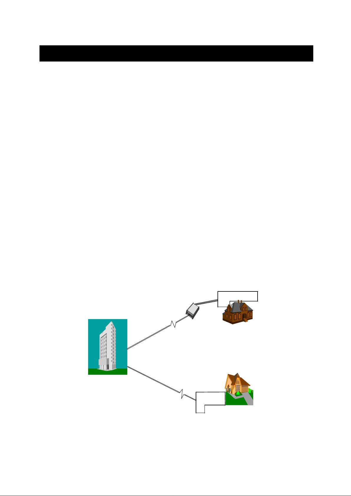
There are two types of ISDN interface of ISDN T/A 128 adapter, ST and U interface. If
you purchased the ST interface adapter (eg. IA128-ST), you need an ISDN NT1 device
connect to the ISDN switch. If you purchased the U interface adapter (eg. IA128-U), it
can directly connect to the ISDN switch. (figure 1-1)
There are two types of PC buses of ISDN T/A 128 adapter, ISA and PCI. Each bus (ISA
or PCI) and each interface (ST or U) has two models option, “D” and “DV”. All of the
features between “D” and “ DV” models are the same, except “ DV” model provides an
extra standard a/b (POTS) port.
IA128-ST
IA128-U
Figure 1-1 ISDN T/A 128 adapters connection diagram
You can easily get the information from “IA128-U-DV” type are ISA bus, ISDN card, U
1
Page 5

interface and a/b port connections. Of course, “IA128P-ST-D” means PCI bus, ISDN
card, and ST interface connection only. “IA128” implies Planet’ s ISDN PC internal
adapter.
All of the current analog devices, including telephone set, G3 fax, answering machine,
modem, and PBX trunk line can be connected to the a/b port (RJ-11 jack) in “DV” model.
The data transmission rate of the “DV” model can up to 64 Kbps while analog
communication on-line, or up to 128 Kbps through Multilink PPP connection.
The Features of ISDN T/A 128 Adapters
You can use the ISDN T/A 128 adapters for Internet access, file transfer, remote access
to the computer network, and running existing modem applications through the ISDN
network.
The valuable applications and specifications of ISDN T/A 128 adapters
u PnP with 16 bits address decoding. Supporting of Windows 3.1, 95 (OSR-2),
98, and NT. Even the BIOS not support PnP, ISDN T/A 128 adapters still
automatically choose the appropriate IRQ and memory address.
u Supporting Linux system (optional feature).
u Global ISDN D channel protocols support. Supporting of Euro-ISDN (DSS1,
and 1TR6), Japan INS-64, US standards of NI-1 & NI-2, AT&T 5ESS, and
Nortel DMS-100.
u Full B channel protocol set support, including V.110, V.120, HDLC, X.75
(Transparent, T70NL, EuroFT), PPP, MLP, async. to sync. PPP conversion,
and MLP+BOD.
u MLP+BOD. Customers can use the Dialup Networking and select our MLP or
MLP+BOD virtual modem to get 128K connection. The BOD is based on the
data traffic, voice call … to drop/establish another B channel for saving time
and money.
u Supporting the application interfaces including WinISDN, CAPI 2.0, Windows
Comm. API with AT command sets, and NDISWAN Miniport.
u Supporting the popular modem application with ISDN throughput and digiTAl
transmission quality, eg. PC Anywhere.
u Supporting of other applications, eg. RVS-COM, WinGate, cfos, CuSeeMe,
Microsoft's HyperTerminal.
u Comm. server capability in the Windows NT Server. It could be used as
Internet comm. server in the ISP, RAS applications for SOHO market, and
connection into Internet shared by all of the LAN users!
u LINETEST feature tests the ISDN line conditions for trouble shooting.
u LOG feature provides the embedded protocol analyzer to decode D-channel
signaling information and raw data on two B channels.
u Supporting IDSL technology solution without need ISDN switch inter-
connection.
2
Page 6

u Supporting multi-language of MS Windows drivers and quick installation guide.
u Supporting the multi-processors of Windows NT platform.
u All of the ISDN T/A 128 passive cards with the same driver, no matter ISA or
PCI bus, or current version or new version. The latest ISDN T/A 128 drivers
from web-site download can backward compatible with ISDN T/A 128 passive
cards.
Why ISDN?
The ISDN (Integrated Services Digital Network) is the standard for carrying both data
and voice simultaneously. ISDN BRI (Basic Rate Interface) line provides two BChannels for voice or data transmission, and each B-Channel can provide data
transmission of up to 64 Kbps. The ISDN network uses the same transmission lines as
the existing analog telephone network, but using a digital signal and higher bandwidth
between the central office (phone company) and the customer. Aside from four times
faster than a standard 28.8 Kbps modem, ISDN also provides an extremely reliable and
stable digital connection.
The ISDN network can set up a connection in about 3 seconds. This is much quicker
than the PSTN network. This feature alone can result in great time savings in the longer
term.
Why High Speed Analog Modems Can Not Compete With ISDN Digital Connections?
“The high speed modem can run at 28.8 Kbps and will move data at ISDN-type speeds
when you consider data compression”. This assumes a noise-free telephone line and
that the data is easily compressed. Unfortunately, many image files cannot be
compressed easily, and many telephone lines are far from ideal. ISDN always operates
at its rated speed. Of course, ISDN cards can also use data compression technology to
multiply its raw data transmission speed.
Telephone monopolies allowing, ISDN will inevitably replace the existing analog
telephone network. The conversion is being driven by applications such as
telecommuting, home-working, remote LAN access, video conferencing and access to
the Internet. Today, ISDN is available almost everywhere so all users can should be
able to get the benefits from ISDN now.
3
Page 7

Chapter 2 Before Installation
Before installation ISDN T/A 128 adapter, you need to check the package contents,
apply an ISDN BRI line, get a NT1 device (for ISDN T/A 128 ST adapter only) from your
phone company or retailed stores, and apply an Internet access account (if Internet
access required).
After you prepared the above items, you can start your environment setup. If you
purchased the adapter is “DV” model, you can connect your analog device to the RJ11 jack (in the UK an adapter is supplied).
Package Checklist
In your ISDN T/A 128 package, you will find the following contents.
u ISDN T/A 128 adapter 1 piece.
u Installation Disk of CD-ROM for Windows 3.1, 95, and NT.
u RJ-45 cable 6 feet for ISDN connection.
u RJ-11 cable for a/b port connection (DV model only).
u USB cable (USB model only)
u (Quick) Installation Guidefor ISDN T/A 128 adapter.
u RJ11-BTS adapter UK only phone adapter.
Suggested System Environment
u Hardware IBM PC (or compatible computer) with 16 MB or more of RAM,
486 CPU or later capable of running Microsoft Windows.
u Software Microsoft Windows environment (Linux is the optional O.S.).
ISDN BRI Line
Before running the ISDN T/A 128 adapter, you need to get an ISDN BRI (Basic Rate
Interface) line from your local telephone company. Sometimes, your ISP may, upon
your request, order an ISDN BRI line for you when you apply an ISDN Internet access
account.
You should get the subscriber information from your ISDN telephone company, who
may inform you about your ISDN central switch type and SPID (Service Profile Identifier)
number, when you are in the US country.
4
Page 8

What is SPID?
SPID stands for Service Profile ID. The SPID is applicable to the US country only.
SPIDs are a series of numbers that informs the central office switch which services and
features to provide to an ISDN device. The generic SPID format comprises 14 digits.
The first 10 digits are the main telephone number on the terminal. The last 4 digits are
dependent on the number of terminals on the interface and the services they support.
NT1 Connection
The ISDN U-loop is terminated by NT1 device at the customer premises. The
connection between the NT1 and Terminal Adapter (ta) is called point “T”. The NT1
drives a 4-conductor S/T-bus which may be expanded to 8 conductors to provide for
emergency power. If your ISDN product with a S/T outlet interface, you need an NT1
device connect to the ISDN switch. ISDN T/A 128 ST adapter needs an NT1 device to
connect to the ISDN switch, but ISDN T/A 128 U adapter does not require NT1 device.
In the UK, and in many European countries, an NT1 device is supplied by your
telephone company. Therefore the ST adapter are required for these countries.
Internet Access Account
If you want to use ISDN T/A 128 adapter to connect to the Internet, you must get an
Internet access account from an ISP (Internet Service Provider) around your location.
You must also confirm with your ISP that they support ISDN access (either single
channel 64K or 128K MLP).
Environment Setup
All ISDN T/A 128 adapters are truly Plug and Play (PnP) compatible. Even if the BIOS
or computer main board does not provide PnP feature, the ISDN T/A 128 device driver
still can automatically configure ISDN card with proper I/O addresses and IRQ number.
1. Terminator setup of ISDN T/A 128 ST adapters (IA128-ST, IA128P-ST,
UI-1280ST)
F Please jump to the next section (2.) if you are the user of U interface adapter,
IA128-U or IA128P-U.
ISDN S/T interface can support up to 8 ISDN terminals and through NT1 device
connecting to the ISDN network. One and only one ISDN S/T device should have
the terminator enabled. Normally the ISDN terminal which is farthest from NT1
should have the terminator enabled.
ISDN T/A 128 ST adapter provides two jumpers of JP1 and JP2 (or DIP switch in
5
Page 9

USB T/A) for the terminators setup, the default setting of ST adapter with terminator
enabled (DIP switch in ON). If there are other ISDN devices connected to the NT1
with ISDN T/A 128 ST adapter, and you do not need the ISDN T/A 128 ST adapter
as terminator, then please remove the JP1 and JP2 (open circuit, DIP switch in
OFF).
2. Insert the ISDN T/A 128 adapter
a. Turn off your computer power and remove the lid.
b. Insert the ISDN T/A 128 adapter into a spare PC ISA (or PCI) slot and secure it.
c. Replace the lid.
If you have UI-1280ST (USB) device, you can connect to the USB port directly.
3. Analog device connection (DV model only)
“DV” model of ISDN T/A 128 adapter provides a POTS interface (a/b port) with
RJ-11 jack to connect with current analog devices. Users can connect analog
telephones, G3 fax, modem, or answering machine with the RJ-11 connector cable
into the RJ-11 jack of the ISDN T/A 128 adapter. In the UK an adapter is supplied to
convert from the UK type 103 plug to the US RJ-11 plug. The REN (Ringer
Equivalence Number) drive capability or parallel ring number is 3, so you can
connect up to 3 analog devices, assuming each device has a REN of 1.
4. ISDN connection
Connect the ST (IA128-ST, P-IN110-ST or UI-1280ST) adapter and NT1 with RJ-
45 cable connector, and insert the ISDN BRI line into the correct NT1 socket.
OR
Directly Insert the ISDN BRI line with the RJ-45 connector cable into the RJ-45 jack
on the U (IA128-U or IA128P-U) adapter. Please kindly be informed that even RJ45 connector has 8 pins and RJ-11 has 4 or 6 pins, but you can still plug cable from
wall jack with RJ-11 connector into RJ-45 jack on the U adapter. The ISDN T/A 128
U adapter still works correctly.
6
Page 10
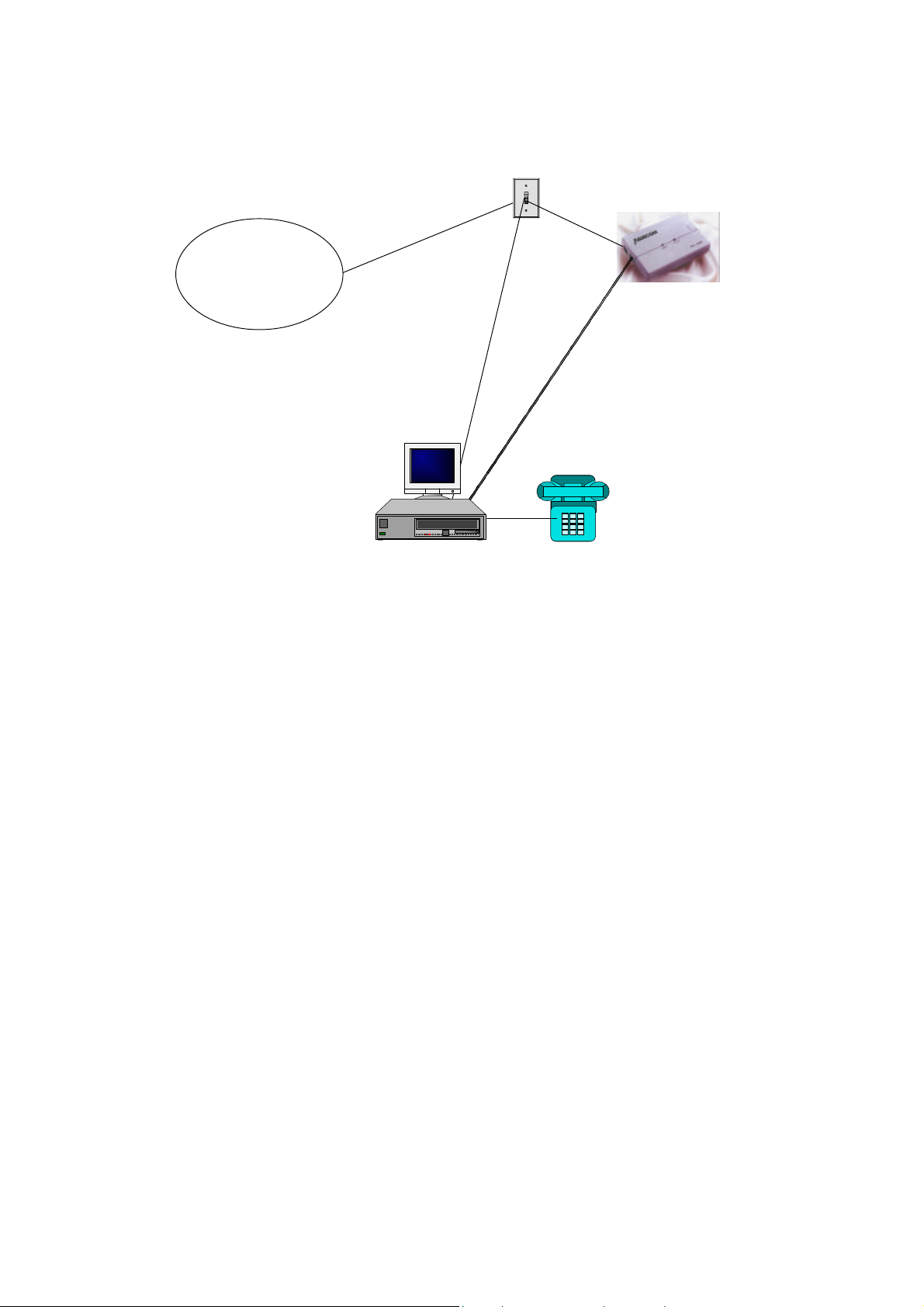
ISDN
ISDNLINK U adapter connection
ISDNLINK ST adapter connection
Figure 2-1 ISDN T/A 128 adapter setup environment
Now, your ISDN PC environment is ready for installation. Figure 2-1 describes the
setup environment. The ISDN T/A 128 ST adapter attaches to the ISDN T interface
from NT1 and the ISDN T/A 128 U adapter attaches to the ISDN U interface directly with
ISDN switch.
7
Page 11

Chapter 3 Installation
After you setup your ISDN environment as figure 2-1 described. Now, turn on your
computer power ON and start the driver installation. ISDN T/A 128 adapters support
Microsoft Windows environments, please read the appropriate installation section
for your PC system and ISDN devices. Linux system is also supported optionally.
The ISDN USB T/A (UI-1280ST) provides the Windows 98 and 2000 only.
Installation for Windows 3.1 Environment
Windows 3.1 installation only available for ISDN T/A 128 ISA adapters. You can install
the ISDN T/A 128 ISA adapters with ISDN connection either through COM port emulation,
or the standard WinISDN interface, or standard the CAPI 2.0 interface in Windows 3.1.
Please read the following steps.
Installing and Configuring the Drivers
1. Insert the ISDN T/A 128 installation CD/diskette into the disk drive.
2. Select the “File” menu from the Program Manager, then choose the “ Run” item to
execute the “Setup.exe” file on the disk drive. The ISDN T/A 128 installation software
will automatically process the necessary setup steps.
3. ISDN Configuration. After step 2. completes, setup will automatically pop-up the ISDN
Configuration dialog box (see figure 3-1). Please fill the necessary information in the
text boxes of ISDN Configuration dialog box.
u
ISDN Switch Type. Choose the country name for your location, or select an
appropriate ISDN switch type in your country (especially for US customers).
u
Codec. Countries follow the European telecommunication standard may choose
A-Law. Countries follow the US telecommunication standard may choose u-law.
u
Standby Time. This is a timer which wait any keypads input from analog device
before sending message out. Please leave it as the default value.
u
MSN (POTS). MSN (POTS) parameter is used for ISDN switches supporting MSN
(Multiple Subscriber Number) service. MSN service is supported by some
European telephone companies. If you enter the number here then the called
telephone number of incoming call will be required to match the MSN (POTS) value,
8
Page 12
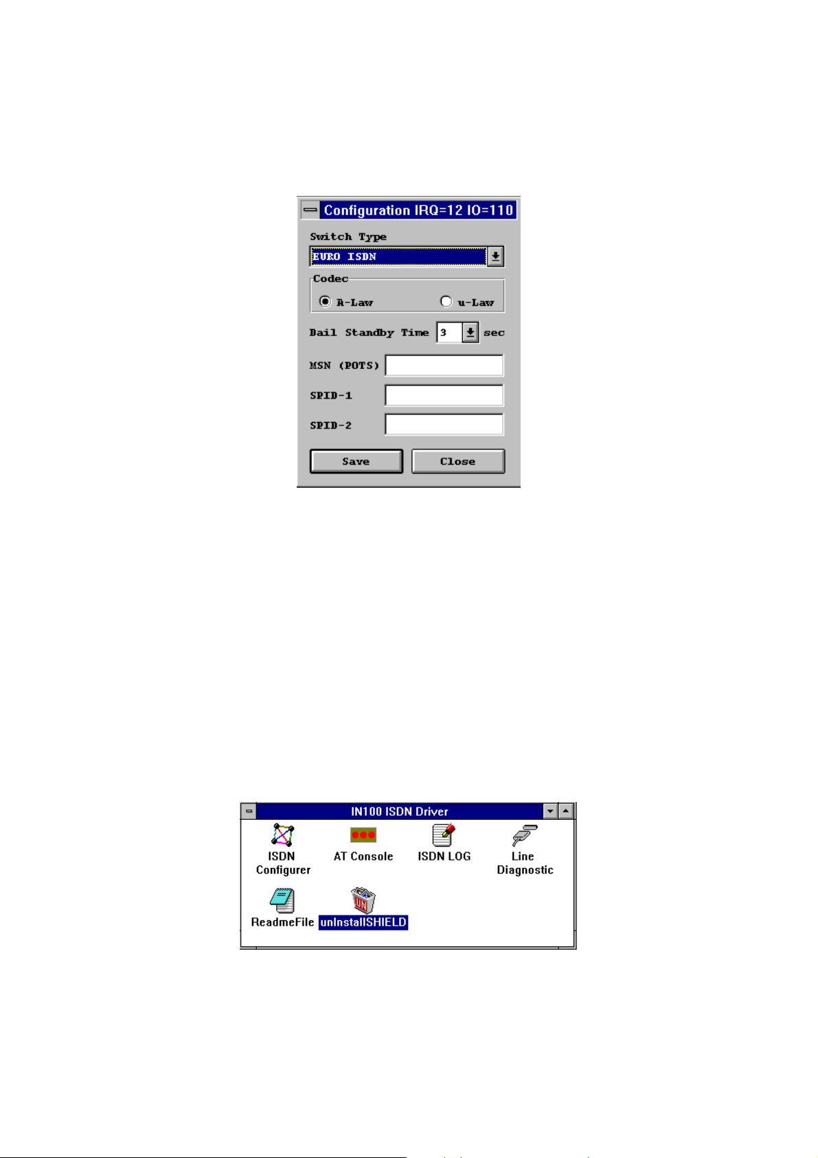
otherwise the analog device connect to the POTS (a/b) port will not be enabled.
u
SPID-1 and SPID-2. SPID parameters only need to be setup for some US
customers, please check with your telephone company if it is necessary.
Figure 3-1 ISDN configuration
4. Now you have finished installation of ISDN T/A 128 adapter, please restart windows.
The ISDN T/A 128 driver will be automatically loaded after started the Windows 3.1, and
the ISDN T/A 128 group folder appears as figure 3-2. The ISDN LOG application is used
to record the handshaking and data transfer process during the communication. It can
be used for debugging purpose so it is often useful to have the log running while first
starting to use the ISDN system. The Line Diagnostic is used for on-line channels test
between ISDN switch and subscriber site, and to get the ISDN line status. Please refer
to chapter 5 for detailed information.
F
You can re-configure the parameters of step 3 by executing ISDN
Configurer in the ISDN T/A 128 group folder. The Configuration dialog
box also displays IO address and IRQ value in the message bar.
Figure 3-2 ISDN group folder
Application Environment Setup
9
Page 13

Under Windows 3.x applications can use the ISDN T/A 128 device using either COM
port emulation, the standard WinISDN interface, or the CAPI 2.0 interface.
1. COM Port Emulation. The ISDN T/A 128 driver provides AT Command Set
interpreter to emulate modem’ s actions and transfer/receive data through the ISDN
network. For modem users need set up the application software to the appropriate
COM ports (COM3 or COM4) to communicate with ISDN T/A 128 adapter. AT
Console program (see figure 3-2) can redirect the AT commands and data through
COM3 or COM4 to the ISDN T/A 128 driver to process them.
If you want to setup Internet environment through COM port emulation then
TRUMPET is the popular Internet shareware and includes the TCP/IP and PPP
protocols with Winsock interface. Most Windows 3.1 Internet modem systems use
TRUMPET connect to the Internet and run Internet applications such as Netscape
Navigator. The TRUMPET user should modify the Network Configuration and Script
files to access the Internet through ISDN T/A 128 adapters. See the Appendix C, the
example of modification of TRUMPET setup.
u
When entering the windows 3.1 system, you must run the AT Console to enable
the COM port emulation capability.
u
Multilink PPP is not supported at the AT-Console. You may get Multilink PPP
connection through the applications which include TCP/IP & Multilink PPP
stack with WinISDN or CAPI interface.
2. WinISDN Interface. The ISDN T/A 128 driver can transmit/receive data with
applications through the standard WinISDN interface. The following TCP/IP stacks
support the WinISDN interface.
u
NetManage’ s Chameleon
u
FTP’ s Explore
u
Frontier’ s SuperHighway Access
Please refer to their respective documents to setup the dial-up environment for
WAN and LAN. We recommend NetManage’ s Internet Chameleon (version 4.5 or
later) for compatibility using both PPP and Multilink PPP.
3. CAPI Interface. Applications can also access the ISDN T/A 128 card for up to 128K
data transmission and receiving through the standard CAPI 2.0 (or later) interface.
Removing ISDN T/A 128 for Windows 3.1
If you want to remove ISDN T/A 128 driver from your Windows 3.1, please click the
unInstallSHIELD icon (see figure 3-2).
10
Page 14
Installation for Windows 95 Environment
This section includes the installation of ISDN T/A 128 adapter and application environment
setup. The supported application interfaces including WinISDN, CAPI 2.0, NDISWAN
Miniport adapter, and virtual modem in Windows 95.
Please read the following Windows 95 installation steps and setup procedures of the
NDISWAN Miniport adapters and virtual modems.
Installing and Configuring the Drivers
1. After you have inserted the ISDN T/A 128 adapter, switch computer power on and allow
Win95 to startup. When the Windows 95 system starts it should auto-detect a new PnP
card and request you to install its driver. Please insert ISDN 128K driver diskette/CD
into appropriate disk drive, run the ISDN100.INF file from the installation
diskette/CD, then Windows 95 system will automatically process the necessary
installation steps.
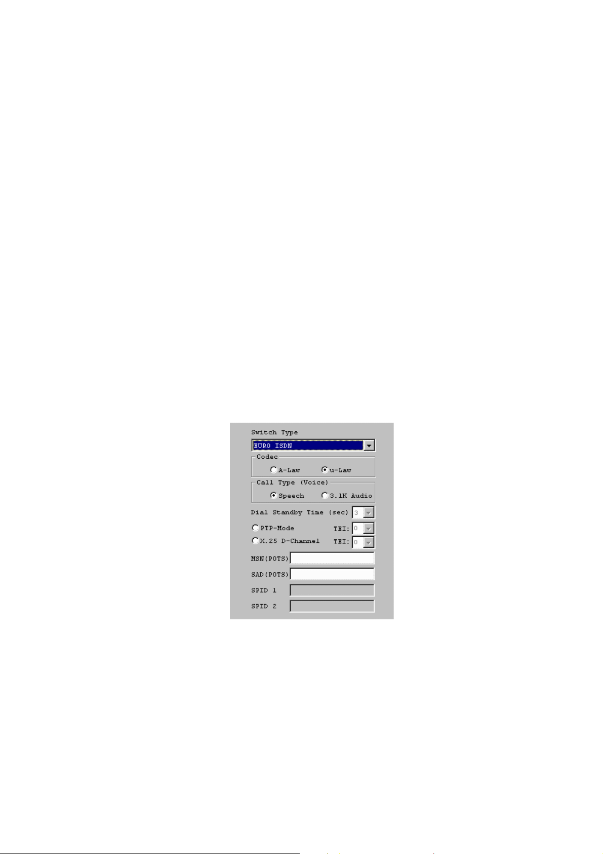
2. Please refer figure 3-3 for ISDN Configuration dialog box. In Windows 95 system, you
can set up (or change) the ISDN configuration of Switch Type, values of MSN and SPID
through the following procedures. Start à Settings à Control panel à System à Device
Manager à ISDN Card à ISDN PC Adapter, Properties à Settings.
Fig. 3-3 ISDN T/A 128 Adapter configuration
This features of ISDN configuration in Windows 95 is similar with the installation in
Windows 3.1 environment as figure 3-1. The MSN (POTS) value is only relevant to the
DV model and determines which telephone number to associate with the POTS
interface e.g. if the number 341317 was entered, then a normal telephone attached to
the POTS interface would be only rung when incoming call with the number of 341317.
11
Page 15

If you want your analog device always ringing when receiving an incoming call,
please keep this field blank. For the UK and most European countries select the
EURO ISDN switch type with A-law Codec. The PTP mode sets the ISDN line as
point to point mode, you may set TEI value also if phone company specifies the TEI
value to you. Otherwise, let it as default (blank). The X.25 on D enables driver to
provide X.25 on D channel service and specify the TEI value also. Please leave it as
default value (blank) if it is not available in your ISDN service list.
3. After configuring the switch type, Windows 95 will request to restart system. After
restart the Windows, if you choose the “DV” model then you can connect a standard
analog telephone set into RJ-11 jack and should be able to hear the dial tone from the
telephone handset.
4. If you already installed the ISDN Accelerator Pack 1.1 (MSISDN11.EXE) or Dial-Up
Networking 1.2 (MSDUM2.EXE) in the Windows, then directly jump to the
application environment setup section. You may check from the property of
connection icon in Dial-Up Networking folder, if you see the “set additional devices” in
the general subwindow or “MultiLink” tab, it means your Windows 95 system already
support NDISWAN interface, please jump to the application environment setup section.
To update the Dial-Up Networking to support 2B channel (MLP) connection and
NDISWAN Miniport interface you will need to install the Win95 MSISDN11.EXE
(version 1.1 or above) upgrade pack. You can get the file from our Windows 95
installation diskette and also accessible from Microsoft web site. Run the
MSISDN11.EXE or MSDUM2.EXE program and follow the installation instructions.
5. Please reboot your PC for effectively ISDN Accelerator Pack features.
Application Environment Setup
After you complete the ISDN T/A 128 driver installation, you can execute the applications
based on the WinISDN and CAPI interfaces. Of course, you need installation the software
before executing the applications, please see the example of Appendix C for RVS-COM (lite
version) software installation. In Windows 3.1, you need to run the AT Console to enable
the COM port emulation capability. Under Win95 the COM port emulation is automatically
loaded at startup.
You can choose the either way of NDISWAN and virtual modem to connect to the
Internet or remote LAN. If you want to execute the Internet related applications or
RAS, we suggest that you setup and use the NDISWAN Miniport adapter interface.
Using the NDISWAN Miniport driver is the Microsoft preferred connection method.
If you want to execute the current modem applications, eg. Microsoft’ s
HyperTerminal or PC Anywhere, you should setup and use the virtual modem
interface through our COM port emulation function (we named the virtual modem).
12
Page 16
1. Connection through the NDISWAN Miniport Adapter
You must install the Microsoft ISDN Accelerator Pack 1.1 (MSISDN11.EXE) or
later version (eg. MSDUM2.EXE) before install the NDISWAN Miniport driver.
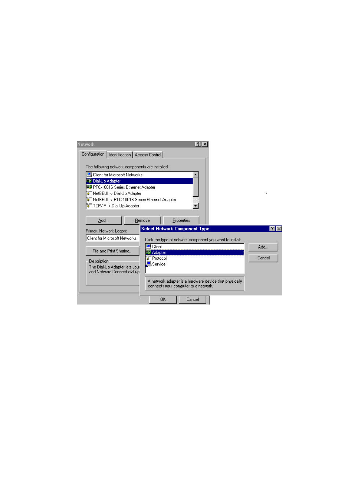
a. Add NDISWAN Miniport driver. Please refer the following steps to add
NDISWAN Miniport driver. Start à Settings à Control Panel à Network à Add
à choose Adapter, Add à Have Disk. Specify the directory for the iinwan95.inf
file (under installation diskette of NDISWAN directory, e.g. A:\NDISWAN), click
OK.
b. Win95 will say that it has found one compatible device. Click OK and Windows
will install the IINWan95-ISDN adapter and bind the NDISWAN protocol to this
ISDN adapter as follows.
13
Page 17
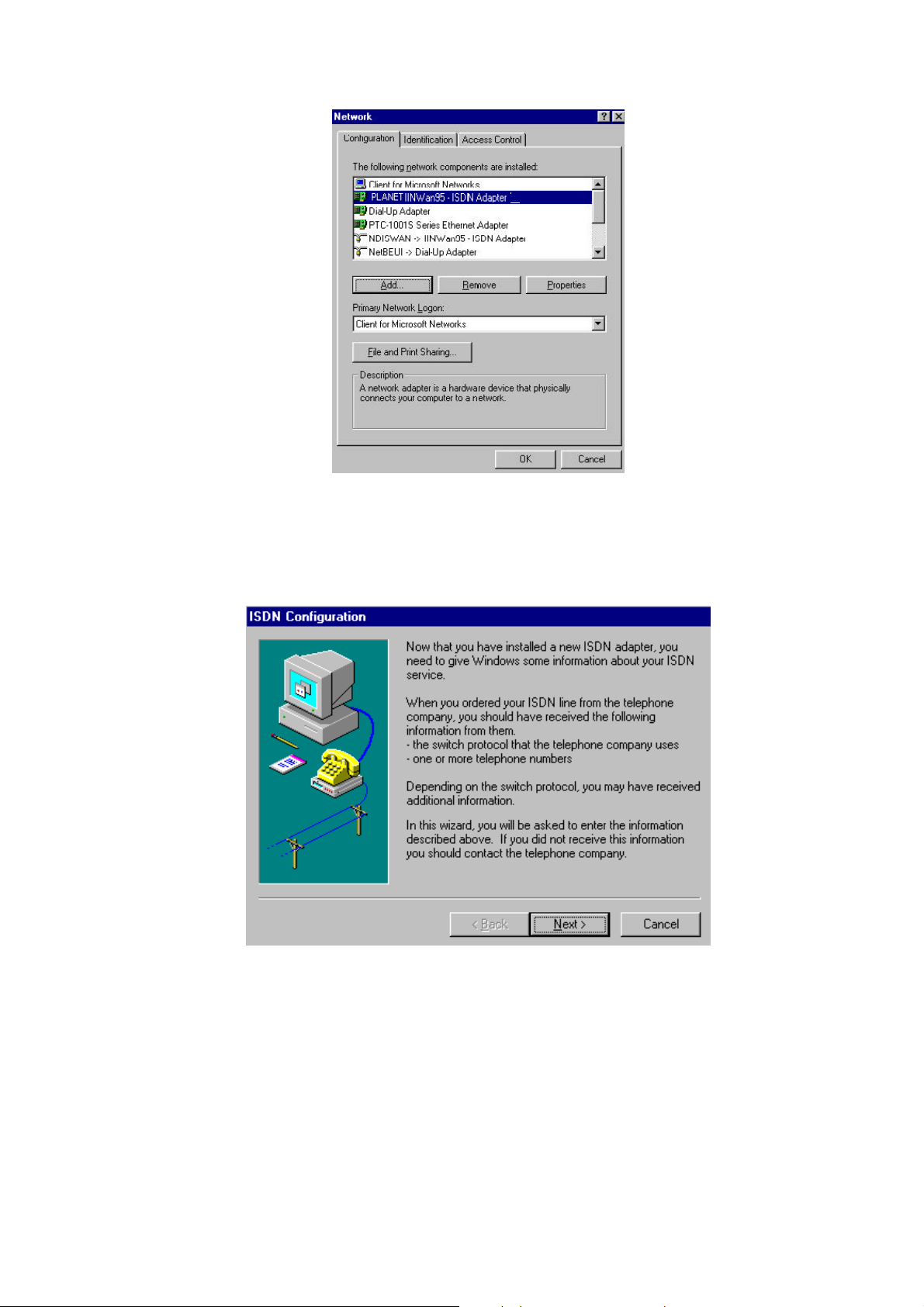
c. Click OK, you will see an ISDN Configuration window as follows. Because you
have installed our ISDN NDISWAN driver, the ISDN Accelerator Pack requests
some information about your ISDN service. Click Next.
d. Select “Automatic” for Switch protocol, click Next.
e. Leave the Phone number and SPID fields blank. Click Next, Finish, then reboot
the system to take effect the setting.
f. Configure the Dial-Up Networking to access Internet. Now when you use
the dial-up networking to create a new connection (Start à Programs à
Accessories à Dial-Up Networking à Make New Connection), you can select
the first device of IINWan95 in the connect using field. (such as IINWan95Line01 in this case, the real number assigned by Windows system). See figure
14
Page 18
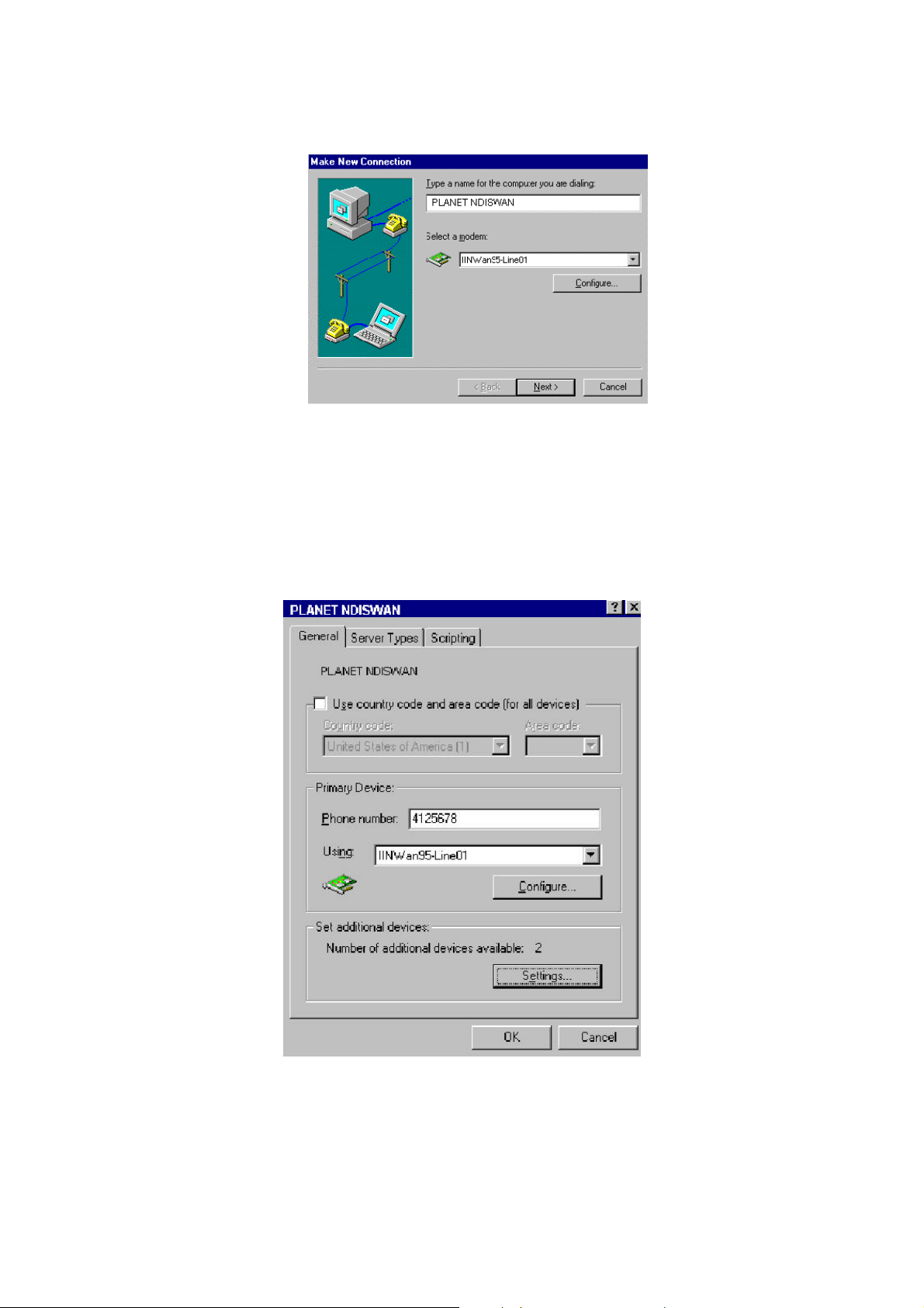
3-4. Click Next.
Fig. 3-4 Dial-Up Networking Setup through NDISWAN - 1
g. Type the phone number which you need connect to your ISP or remote LAN.
Click Next, Finish. You will see a new connection icon (PLANET NDISWAN) be
added into Dial-Up Networking folder. Choose the new connection icon,
click the right mouse button, choose Properties. You will see the picture as
follows.
Fig. 3-5 Dial-Up Networking Setup through NDISWAN - 2
h. If you want to use 128K MLP (check your ISP supports this feature) connection,
you need choose another IINWan95 device. In figure 3-5, Settings à Use
additional device à Add à select the second IINWan95 device (IINWan95-
15
Page 19

Line02 in this case). Please see figure 3-6 for 128K MLP setup.
Please ensure that you choose the correct ISP settings such as Server Type and
TCP/IP values. Please contact your ISP or refer figure 3-7 as an example. You are
now ready to make a connection to your ISP and access the Internet through
the NDISWAN Miniport adapter!
Fig. 3-6 NDISWAN 128K MLP Setup
16
Page 20

Figure 3-7 example of Server Types and TCP/IP Settings
Configure the NDISWAN adapter
There are four parameters need to be configured. Please refer the below figure by
clicking Start à Settings à Control Panel à System à Device Manager à Network
Adapters à ISDN adapter, Properties.
The MSN1 and MSN2 are used for filtering the incoming call in separated ISDN
port1 (ex. IINWan95-Line01) and ISDN port2 (ex. IINWan95-Line02). For example,
if you want ISDN port 1 to receive telephone number 12345 only, you can enter
12345 into MSN1. The subaddress works like an extension number that your local
ISDN switch must provide this feature also. Usually, leave these fields with blank.
The Calling Party 1 and Calling Party 2 are used to indicate the ISDN switch (PTT)
that this call is made from this telephone number and bills the communication cost
based on this telephone number. Be noticed that MSN1 and Calling Party 1 are
reserved by ISDN port1, the MSN2 and Calling Party 2 are reserved by ISDN port2.
17
Page 21

Planet
2. Connection through the Virtual Modem
After the successful installation of the Win95 drivers, two extra of virtual ISDN COM
ports will be automatically created. You need check the virtual COM port value, add
the modem (virtual) connection with the ISDN COM port, and check the virtual
modem parameter’ s value. You can refer the Chapter 4 about AT Command Sets
descriptions.
a. Check the virtual COM port value. Please refer figure 3-8 for details of the
ISDN COM port Configuration dialog box. If there is any parameter which does
not match with our suggested value, then please alter it accordingly. Even you
choose “115200” at the “ Bits per second” field, the actual physical connection
speed is “128000” when connection with 128K connection (MLP).
Our recommended values as follows.
Bits per second: 115200
Data bits: 8
Parity: None
Stop bits: 1
Flow control: None
FIFO control: None (fill at Advanced tab)
c.
Select the Start à Settings à Control Panel à System à Device Manager à
Ports (COM & LPT), ISDN ComPort1 / ISDN Comport2, Properties à Port
Settings to check the ISDN COM1 / ISDN COM2 port parameters.
e.
18
Page 22

Figure 3-8 ISDN ComPort configuration
b. Adding virtual modems connecting with two ISDN COM ports. You can
add virtual modem with ISDN T/A 128 proprietary virtual modem. For
installation convenience and flexible usage, ISDN T/A 128 driver provides
several proprietary virtual modems in Windows 95. We list the following
procedures as the examples to add ISDN T/A 128 virtual modems in Windows
95.
1) Select Start à Settings à Control panel à Modems à Add à Select “do
not detect my modem, I will select it from a list”, Next
2) Click “Have Disk”, and browse to the MODEM sub-directory on the
Windows 95 installation diskette (eg. A:\MODEM). Select the mdmasu.inf
file. Choose the appropriate modem type from the Models’ text box. (see
the Install New Modem dialog box below)
19
Page 23

3) Click on Next, then link this modem to the ISDN Com Port.
Each modem type will automatically issue the appropriate protocol command to
ISDN T/A 128 driver when you select it to make a connection.
The ISDN T/A 128 modems are used for following purposes.
u
The Async to Sync PPP (Internet PPP, 64K) modem is used for 64K
Internet Access.
u
X.75 Transparent modem is used for BBS Access and file transfer.
u
The Universal-1 and -2 are multi-purpose modems. With the Universal
modem mode, the ISDN driver selects HDLC as default, but you can change
to the appropriate protocol through our supported ATBn commands in
Chapter 4. Before making a connection, you can change through Start à
20
Page 24

Settings à Control Panel à Modems à ISDN modem, Properties à
Connection, Advanced à Extra settings (see figure 3-10). You can use the
Universal modems for 128K MLP Internet access, in which case both ISDN
ports must have the Universal modem selected.
*
Please refer the Appendix D for more valuable ISDN T/A 128
modems.
c. Check the virtual modem parameter value. Please check (and modify if
necessary) the default modem setting pertaining to each of the two ISDN COM
ports/modems. Select Start à Settings à Control Panel à Modems à ISDN
modem for ISDN ComPorts (eg. In figure 3-9), Properties à Connection, set
Data bits to 8, Parity to None, and Stop bits to 1. Do not select to use FIFO
buffers in Port Settings tab and do not select flow control in Advanced tab.
Please refer to figure 3-9 and 3-10 about modem configuration.
Figure 3-9 ISDN MODEM Parameter Configuration - 1
21
Page 25

Figure 3-10 ISDN MODEM Parameter Configuration - 2
d. Configure the Dial-Up Networking to access Internet. Please see the
examples of 64K and 128K Internet connection with Dial-Up Networking
through the ISDN T/A 128 virtual modem.
64K Access
1) You can make a new connection from the following steps. Select Start à
Programs à Accessories à Dial-Up Networking à Make New Connection.
Select the ISDN (Async to Sync PPP, 64K) Adapter modem, click
Configure tab, make sure the modem either connection to the ISDN
ComPort1 or ComPort2. (see figure 3-11)
2) Please ensure that you choose the correct ISP settings such as Server Type and
TCP/IP values. Please contact your ISP or refer figure 3-7 as an example. You
can change or check the parameter’ s setting of Dial-Up Networking
from Start à Programs à Accessories à Dial-Up Networking, choose
the connection icon, then click the right mouse button choose
Properties. You can also input the dial-up ISDN phone number from
General tab.
3) Now, you are ready to make a connection to your ISP and access the Internet
22
Page 26

through the our virtual modem interface (64K connection), and enjoy the related
Internet applications.
Figure 3-11 Choose ISDN (Internet PPP, 64K) Adapter
128K/MLP Access
1) If you want to make a connection with 128Kbps, then first of all please
confirm that your ISP supports 128K MLP - some don’ t or if they do then
often they will only allow this service at extra cost. Secondly you must have
installed the Internet MLPPP or MLPPP+BOD (128K) modem from
MDMASU.INF as Appendix D.
2) The other setting is the same as above.
Removing ISDN T/A 128 for Windows 95
To remove ISDN T/A 128 128K drivers from Windows 95 use the following steps.
1. Remove the NDISWAN adapter (NDISWAN driver), please do not select reboot
windows after removing. Start à Settings à Control Panel à Network, choose
PLANET IINWan95 - ISDN Adapter, à Remove.
2. Remove all of the virtual modems associated with ISDN T/A 128 adapter COM ports.
Please do not select reboot windows after removing Start à Settings à Control
Panel à Modem, Remove.
3. Remove the ISDN adapter from multifunction adapter. Please do not select reboot
23
Page 27

windows after removing. Start à Settings à Control Panel à System à
Device Manager à Multi-function adapters à ISDN PC Adapter, Remove.
4. Run "iinclean.exe" located in installation disk to move away files and system
information from Win95.
5. Reboot the windows to take effect.
Installation for Windows 98 Environment
There are two types of Windows 98 drivers (VxD and WDM) at the installation CD-ROM
diskette. Both of the installation programs can install the ISDN driver, virtual COM port,
and NDISWAN Miniport driver at that same time.
VxD
Windows 98 system includes the NDISWAN Miniport interface, so you do NOT need to
install the ISDN pack (MSISDN11.EXE), and just choose the “isdn98” file from the
“Win98/VxD” subdirectory of installation CD-ROM when Windows 98 detects an ISDN PnP
card and requests to install its driver. The installation program will automatically process the
necessary installation steps for you (including the NDISWAN Miniport driver installation). To
configure the driver and setup application are the same as in above installation for Windows
95 environment section.
WDM
This section describes the installation of ISDN T/A 128 Win98 WDM driver. This driver
can be used for ISDN Internal cards, USB T/A and T/A. The supported application
interfaces including WinISDN, CAPI 2.0, NDISWAN Miniport, and virtual modem in the
Windows 98. The ISDN T/A 128 WDM driver also supports the multi-ISDN T/A 128
adapters in one PC system.
Installing and Configuring the Drivers
1. After you insert the ISDN T/A 128 adapter, power the computer switch ON, the Win98
will start up. Then the Windows 98 will automatically detect a new PnP card and
request you to install its driver. Please click “Next”, check “ Search for the best driver
for your device” and “Next” . Then insert ISDN T/A 128 driver diskette/CD into the
appropriate disk drive, run the ISDNDV98.INF file from the installation diskette/CD
(under WDM sub-directory), then Windows 98 system will automatically process the
necessary installation steps. The ISDN T/A 128 adapter driver, CAPI20 driver, two
virtual COM ports, and NDISWAN Miniport driver will be installed. This ISDN driver will
start automatically without reboot. You can use CAPI20 and virtual COM ports directly.
But you need to go to ControlPanel -> System -> Devicemanager -> Re-flash, then
NDISWAN mini port driver will be activated. Or reboot to enable NDISWAN miniport
driver. Be noticed, the ISDN pack is included in the Windows 98 as default, so
you do not need to install the ISDN pack again.
24
Page 28

2. After started the Windows 98, there is a small icon in the system tray. This icon is used
to indicate the ISDN line status (D, B1, and B2 channels). The meaning of color of small
square is
RED : the driver is loaded fail or there is no device in the PC. (check our
ISDN configuration window for more information.
YELLOW : the driver is loaded successful and waits application.
GREEN : the driver is loaded successful and application attached.
3. When the cursor points to this icon, it will show driver name, driver version number, and
the monitored ISDN card name. Move the cursor to this icon and click the right button,
you have 4 items in the selection list, Configuration, Line test, Log, and Exit.
Describe Configuration as below.
ISDN T/A 128 Configuration
1. When you select the configuration item, it shows the current ISDN devices in the
Windows 98 with ISDN T/A 128-XX name. The two ISDN T/A 128 ports are under
NDISWAN ports, two virtual com ports are under COM Port, and POTS port if you
choose our ISDN T/A 128 adapter with POTS (A/B) feature (“DV” model).
2. Click the ISDNLink-XX and Properties, you will get the configuration window as below.
25
Page 29

Alias Name Displays the ISDN device name and you may change the name by
yourself. Because this WDM driver supports multi ISDN devices in Windows
98, it is easy to make notes with alias name for each ISDN device.
ID Displays the CAPI application ID and also shows the error reason if ISDN
driver is not able to run.
Interface Shows the ISDN interface (S/T or U interface) of ISDN device.
BUS Shows the PC bus type (ISA or PCI bus) of ISDN device.
Type Shows this ISDN device is an internal card or external device, and Active or
Passive type.
POTS Port Shows how many POTS port supported by this device.
Provide Tone Shows TONE provided or not of ISDN device.
Resource Shows the resource assigned by Windows 98 to ISDN device.
SWITCH Shows the ISDN switch type. This field is changeable.
SPID1/2 Show the SPID1 and SPID2. Both fields are changeable if you select the US
type ISDN switch in SWITCH field such as NI1.
PTP mode Set the ISDN line as point to point mode, you may set TEI value
also if phone company specifies the TEI value to you. Otherwise, let it as
default (blank).
26
Page 30

X.25 on D Enable driver to provide X.25 on D channel service and specify the TEI value
also. Please leave it as default (blank) if it is not available in your ISDN
service list.
MSN List Click this and input MSNs to be a MSN list. If your local ISDN line provider
does not provide this service, please leave it as blank.
3. Click ISDNLink28-XX-LineXX and Properties, you get below configuration window.
MSN Select it from the MSN List as above item. Then when you make a call
through this port, this number will be sent to ISDN phone company for the bill.
You may also enable the filtering function to the incoming call. This means
the incoming call with be matched with this number and accept the incoming
call if match correctly.
SAD Sub-address, it is almost the same as MSN. It depends on the ISDN phone
company. It may provide this service or not.
Protocol Select the outgoing protocol and incoming protocol when make a call or
receive a call through this port. There are three protocols supported, HDLC,
X.75 Transparent, and V.120. Or leave it as auto-detection for incoming call,
27
Page 31

it means driver will detect one of protocols depended on remote device. If
you want to use our MLPPP and MLPPP+BOD function for outgoing call, you
need to check “Enable Multilink PPP” and click “ Advance” to select the
second NDISWAN port and configure the second channel as below.
To check the “Enable BOD” to enable MLPPP+BOD function with two
default parameters, data flow rate (1 Kbytes/sec) and Inactivity timeout (5
minutes). The system will start to establish the second channel if the average
data flow of the first channel exceeds 1 Kbytes/sec during the past five
minutes. At the 128K data connection, If the average data flow lower than 1
Kbytes/sec during past 5 minutes, the system will disconnect one B channel.
During the 128K data connection if the user want to make a voice
call or receive an incoming voice call, the system will automatically
disconnect one B channel to set up the analog voice connection.
To add another NDISWAN port for second channel and click “Edit” to
configure it. The Call No. is the remote telephone number, Call Sub Addr. is
the sub-address (leave it blank if phone company does not provide this),
MSN and SUB for bill as above.
For the MLPPP and MLPPP+BOD of incoming call, it almost the same as
outgoing call, except the filter function. The called number of incoming call
should match the MSN and/or SAD before accepting this call if filter is ON.
Please refer below figure.
4. Click the POTS and Properties if you get the ISDN board with POTS (A/B) port, you get
below configuration window. Please refer the POTS descriptions from the sections of
Windows 31 and Windows 95.
28
Page 32

5. Click 1 under POTS section and Properties, you get below configuration window.
Select a number from the MSN List for MSN. Then when you make a call through this
POTS (A/B) port, this number will be sent to ISDN phone company for bill. You may also
enable the incoming call filtering function. This means the incoming call with be
matched with this number and driver will ring the telephone device if match correctly.
Sub-address (SAD), it is almost the same as MSN. It depends on the ISDN phone
company. It may provide this service or not.
Application Environment Setup
The application environment is the same as in Windows 95 section. User can use CAPI,
NDISWAN, virtual COM port and others to access ISDN driver. But in WDM driver, it
provide more flexible configuration method to enable multi-link and bandwidth on
demand functions.
Removing ISDN T/A 128 for Windows 98
To remove ISDN T/A 128 drivers from Windows 98 use the same steps as described in
“Removing for ISDN T/A 128 Windows 95” section if you install the VxD driver. If you
install WDM driver, please use the following steps.
1. Remove ISDN adapter, please do not select reboot windows after removing. Start à
Settings à Control Panel à System à DeviceManager -> ISDN Controller ->
ISDN Adapter à Remove.
2. Run LNKCLEAN.EXE in our installation driver. It will clear ISDN information away totally.
3. Reboot the windows to take effect.
Installation for Windows NT Environment
In the Windows NT system, the ISDN T/A 128 driver supports of multi-processors
platform. It can benefit to the powerful users running Planet’ s ISDN T/A 128 PC internal
card on the multi-processors NT system.
You can install the ISDN T/A 128 adapter with ISDN connection under Windows NT
29
Page 33

using either the standard CAPI interface, or the NDISWAN Miniport adapter. Please
read the following steps for details of NDISWAN Miniport setup, Dial-Up Networking,
and RAS applications in Windows NT 4.0. The installation for Windows NT 3.51 is very
similar to NT 4.0. Please refer the following steps for Windows NT 3.51 also.
Installing and Configuring the Drivers
After you insert the ISDN card into the available slot and turn on your computer as
described before, your computer should boot into Windows NT. If your Windows NT has
installed the PNPISA before, when system boot up the Windows NT will detect an ISDN
card and request to install its device driver, please check “Do not install a driver” and
follow the instructions below to install the ISDN T/A 128 driver.
1. Click the Network Icon in the Control-Panel and Adapters tab. You will get the below
window.
Figure 3-14 NT Installation
2. Click Add, then you get a window as below.
30
Page 34

3. Click Have Disk tab and specify the Drive and Directory of ISDN T/A 128 NT driver.
4. Select the “PLANET’ s ISDN PC Adapter”, click OK.
5. You will see the ISDN Driver Bus Location dialog box, please fill the Bus Type to ISA
or PCI and the Bus Number to 0, then click OK.
Planet’s
Be noted: Please make sure your ISDN card type and select the right card
type in above figure.
31
Page 35

6. Windows NT copies the ISDN driver into system.
7. The ISDN configuration windows will now be shown as below (figure 3-15). We
provide the IRQ and IO configuration by manually when it is required. But we
suggest that use our Auto configuration first even your BIOS not support PnP feature.
In the ISDN Configuration dialog box, you can fill the “calling party number” and
“calling party subaddress” from NDISWAN Setting tab. If your telephone company
offers the MSN service, you can use these parameters to get the bill of your
respective MSN ISDN telephone number. All of the other parameters please
refer the section above for Windows 3.1, 95 and 98 installation.
Figure 3-15 ISDN Configuration
8. Click OK to continue.
9. If you change any value in the ISDN configuration dialog box, you will be warned that
you will need to restart the Windows NT for the settings to take effect.
10. Click OK to install and setup RAS.
32
Page 36

11. If you have installed the RAS, please refer next step to install ISDN ports for RAS. If
not, please install the RAS now. Please refer figure 3-14, click the services tab to
add RAS. The RAS is provided by Microsoft, you need to prepare the Installation
disks or CD of Windows NT to continually install it. You should jump to next step
when RAS installer asks to add port device.
12. You will get a window like below. If you do not see the ISDN ports with the device
name of IINWANNT, then click the Add tab to add both IINWANNT devices.
13. Select the ISDN1 and click Configure tab to set the parameter (Port Usage) to this
ISDN1port for “Dial out only”, “ Receive calls only”, or “ Dial out and Receive calls”
then click OK.
14. If you choose “Dial out only”, click OK, and then click the Network tab, you will get a
window like below, check which protocol you want. If you are going to access
Internet, choose “TCP/IP” usually.
33
Page 37

15. If you choose “Receive calls”, or “ Dial out and Receive calls”, click OK and then
click the Network tab, you will get a window like below. Please check your ISP or
network administrator for TCP/IP settings (see Appendix C for assistance). Also
check that you have enabled, “allow any authentication including clear text”, in the
Security settings. Then click OK.
16. Select the ISDN2 and do the same things as above, then click Continue tab.
17. At this stage, you have installed the ISDN drivers in your Windows NT successfully,
then click Close tab.
18. You need to restart your computer now.
Configuring an Access Account over ISDN
Now, you need to configure an access account over ISDN in Dial-Up Networking.
34
Page 38

1. Select Start à Programs à Accessories à Dial-Up Networking. And then enter the
name of the new Dial-Up account and click “Next >”. Enter the server type details
for your ISP. Click “Next >” and select IINWANNT and click “ Next >”. Enter the
phone number of ISP and click “Next”. Click “ Finish”. You will get a window like
below.
2. To configure server settings or dialing properties, click on the “More” button and
select the item you want to change from the pull down list. Click “Dial” to make a
connection with server over ISDN. To compare with Windows95 Dial-Up
Networking, these parameters (phone number, dial using port, server type, and
security) are located in the item “Edit entry and modem properties..” when click on
the “More” button. In the “ Security” sub-window, check that you have enabled
“Accept any authentication including clear text”.
3. If you want to use Multilink PPP connection (128Kbps), please follow the steps
below.
a. Click “More” button and select the item “ Edit entry and modem properties”.
b. Under the Basic tab, set “Dial using:” to Multiple Lines.
c. Click Configure and check the check boxes for IINWANNT(ISDN1) and
IINWANNT(ISDN2).
d. Select IINWANNT(ISDN1), click “Phone numbers”, enter the first phone
number, click Add, and click OK.
e. Select IINWANNT(ISDN2), click “Phone numbers”, enter the second phone
number, click Add, and click OK.
f. You are now ready to make 2B connection with server. Please make sure your
ISP or remote server does in fact support 128K MLP and also that it has been
enabled for you by the remote server.
35
Page 39

Accessing the Outside World Using Dial-Up Networking
You are now done with the configuration process and should be ready to make a
connection with your server. Click the Dial-Up Networking icon, and select the name
configured above in the phone book entry and click “Dial”. The system should then dial
and connect to your ISP at either 128k or 64k depending on how you setup the call. The
server will verify your login name, password, and register you on the server.
If you double-click the small icon of Dial-Up Networking at the right-bottom of the
Windows, the Dial-Up Networking Monitor shows your connection status including
connection speed, server type, etc. You are now ready to use the Internet tools to
access the Internet or network tool to access remote network.
If you find problems after connecting such as the line is dropped or you cannot access
the Internet, or you cannot access your remote network, please go back to check your
network settings with your ISP or network administrator.
36
Page 40

Reconfigure the ISDN Settings
If you want to reconfigure the ISDN settings such as Switch type, Codec and so on,
please click the Network icon in the Control Panel and Adapter tab. Select the “PLANET
ISDN PC Adapter” and click Properties. You will see the Bus Location dialog box,
please click OK. Then the ISDN configuration windows will be shown on the screen, see
figure 3-15.
Removing ISDN T/A 128 for Windows NT
Click the Network Icon in the Control-Panel and Adapters tab. You will get the below
window, and choose “PLANET’ s ISDN T/A 128 ISDN Driver”, then click Remove.
Installation for Windows 2000 Environment
This section describes the installation of ISDN T/A 128 Win2000 WDM driver. This driver
can be used for ISDN Internal cards, USB T/A and T/A. The supported application
interfaces including CAPI 2.0 and NDISWAN Miniport in the Windows 2000. The ISDN T/A
37
Page 41

128 WDM driver also supports the multi-ISDN T/A 128 adapters in one PC system.
Planet
Installing and Configuring the Drivers
After you have inserted the ISDN device, switch computer power on and allow Windows
2000 to startup. When the Windows 2000 system starts that it should auto-detect a new
PnP card and requests you to install its driver.
Please click “Next”, check “ Search for a suitable driver for your device” and “ Next”.
Then insert ISDN 128K driver diskette/CD into appropriate disk drive, Windows 2000 will
run the ISDNLINK.INF file from the installation diskette/CD, or you may specify the
subdirectory which contains the ISDN Windows 2000 device driver. Then Windows
2000 system will automatically process the necessary installation steps. After
installation, you can use the ISDN driver immediately without reboot system.
You may run the LINKSTS.EXE program which provides the ISDN monitor (log), ISDN
line test tool and driver configuration functions and it will become an icon and appear
in the system tray. When the cursor points to this icon, it will show application name,
driver version number, and the monitored ISDN card name. Move the cursor to this icon
and click the right button, you have 4 items in selection list, Configuration, Linetest, Log
(ISDN monitor), and Exit. The detailed description is the same as in about WDM of
“Installation for Windows 98 Environment” section. Please refer it for more
information.
Application environment setup
Network and Dial-up Connections
38
Page 42

Click the “Make New Connection” to create a new icon, click “ Next” -> Check the Network
Connection Type (for example, Dial-up to the Internet), click “Next” -> Check “ Connect
using my phone line”, click “Next” -> check “Create a new dial-up connection” , click “Next”
-> Internet Connection Wizard starts, input the ISP telephone number and click
“Advanced…” to set connection type to PPP, Logon Procedure to None, IP address and
DNS server address, click “Next” -> enter User Name and Password, click “ Next” -> Enter
Connection Name, click “Next” -> Click “ Finish” to generate a new dial-up icon.
Click the new dial-up icon to get the property window as below.
Check the ISDN port you want to access Internet with telephone number. Besides, you can
enter the IDLE TIME BEFORE HANGING UP value in the Options tab. In the Security tab,
please select the “Allow unsecured password” to do username and password negotiation. In
the Networking tab, please check PPP in the Type of Dial-up Server and TCP/IP protocol
for communication. Then you can enjoy the Internet resource now with ISDN speed now.
You can download the latest drivers and get the update product news from our web site of
http://www.planet.com.tw. You can send your comments to us by email,
support@planet.com.tw (technical), or sales@planet.com.tw (sales).
39
Page 43

Chapter 4 ComPort Emulator
The ISDN T/A 128 adapters support Microsoft Windows Comm. API interface. This
allows applications (especially popular analog modem’ s applications) to access ISDN
T/A 128 adapters as an emulation modem (this is an emulation does NOT really support
fax or modem features). Windows Comm. API also enables existing applications based
on the AT command set to access ISDN. This feature is called the Comport Emulator
and also allows also extra AT commands to enable ISDN features such as HDLC, X.75,
V.110, V.120, or Async to Sync PPP (see list below).
1. Windows 3.1 system. Windows Comm. API is enabled only after running the
atloader.exe program, (double click the AT Console icon, see figure 3-2). AT
console will not be activated automatically at startup unless you add it to the StartUp
group in Windows 3.1. Normally you should activate yourself.
2. In Windows 95 system. Windows Comm. API is enabled automatically.
F
Windows Comm. API can only provide AT-emulation if the application
requests its COM port services from Windows. It cannot support the
application if it tries to access the com port hardware directly or if your
software does not use the standard Windows comm. driver interface.
The following AT Commands are provided to allow control of the ISDN connections, line
protocols and call handling. You should change your application setup-strings using
these parameters to access ISDN T/A 128 adapter with the correct protocol and settings.
Command Samples Description
Ata Answer an incoming call
ATBn Select protocol of transmission in B channel
ATB0 64K HDLC (default with universal modems under Win95)
ATB11 V.110 Async. User rate = 1200 bps
ATB12 V.110 Async. User rate = 2400 bps
ATB13 V.110 Async. User rate = 4800 bps
ATB14 V.110 Async. User rate = 9600 bps
ATB15 V.110 Async. User rate = 19200 bps
ATB16 V.110 Async. User rate = 38400 bps
ATB32 X.75 ISO 8208
ATB4 Async PPP to Sync PPP converter (default setting with
Win95 Async to Sync PPP modem)
ATB41 Async to Sync PPP conversion in ML PPP mode,
compatible with Microsoft ISDN Accelerator pack
ATB42 Async-to-Sync PPP conversion in MLPPP
40
Page 44

ATB43 Async-to-Sync PPP conversion in MLPPP+BOD
(Bandwidth on Demand)
ATB6 Async-to-Sync PPP conversion over X.75 Trans.
ATB61
Async-to-Sync PPP conversion over X.75, but need to
setup secondary device in Dial-Up Networking
ATB62 Async-to-Sync PPP conversion in MLPPP over X.75
ATB63 Async-to-Sync PPP conversion in MLPPP+BOD over
X.75
ATDs Dial a telephone number
ATDL Dial the last number
ATD7693007 Dial telephone number 7693007
ATEn Echo characters when in command mode
ATE0 Echo off
ATE1 Echo on ( default )
ATHn On-Off Hook
ATH On-Hook, Disconnect (same as ATH0)
ATH1 Off-Hook
ATI Display version number, selected protocol, packet size,
connected speed, MSN, and outgoing call number.
ATO On-Line command, switch to on-line mode from
command mode
ATQn Return the result code
ATQ0 return the result code (default)
ATQ1 does not return the result code
ATSr Set or display the register value
ATS0=1 Set register 0 to 1, (S0=0 default, disable the auto-answer
mode)
ATSr? Display register r content
ATS1? Register 1 is read only, display the ring count
ATS2 Escape code character (S2=43, ASCII “+”)
ATS3 Carriage return character (S3=13, representing a
carriage return)
ATS4 Line feed character (S4=10, representing “CTRL J” or
the line feed character)
ATS5 Back space character (S5=8, representing “CTRL H”)
ATS7 Wait for carries after dial (S7=30 seconds default)
ATS12 Escape code guard time (S12=50 default )
ATS25 Delay to DTR (S25=5 default )
ATS30 Disconnect the connection automatically if there is no
data transmission in n*10 seconds (n=0 to 255, default
S30=0, it will not disconnect the connection)
ATS38 Windows size of HDLC 56K or 64K, 7 default
ATS39 Packet size of HDLC 56K or 64K from 1 to 2048, 2048
default
ATS40 Windows size of V.120, 7 default
ATS41 Packet size of V.120, 256 default
ATS44 Window size of X.75 (Transparent), 2 default
ATS45 Packet size of X.75 (Transparent) from 1 to 2048, 1024
default
ATS46 Window size of X.75 T.70 NL, 2 default
ATS47 Packet size of X.75 T.70 NL from 1 to 2048, 130 default
41
Page 45

ATS50 Window size of X.75 ISO 8208, 2 default
ATS51 Packet size of X.75 ISO 8208 from 128 to 2048, 1024
default
ATS53 Average data flow from 1000 to 7000 bytes (default 4, it
means 4000 bytes)
Active the second channel if average data flow is over
4000 bytes in 10 seconds. This register is only available
in MLPPP BOD mode, ATB43.
ATS54 Time period from 5 to 20 minutes (default 5)
Disconnect the second channel if average data flow
below N bytes (set by ATS53) in 5 minutes. This register
is only available in MLPPP BOD mode, ATB43.
ATVn Verbose command
ATV0 Return digit result code
ATV1 returns word result code ( default )
ATXn Enable extended result code
ATZ Reset
+++ Escape command
AT&Cn Control DCD
AT&C0 Keep always the DCD line ON ( the same as AT&C,
default )
AT&C1 DCD line is active if connected
AT&E Select the line speed in the B channel
AT&E0 64K bps (default)
AT&E1 56K bps
AT&F Reset registers to factory setting
AT&R Request to send
AT&S Handle DSR
AT&S0 Keep DSR always ON ( the same as AT&S )
AT&ZIn*m Filter the incoming call and accept it when called party
number is the same as n and called party sub-address is
the same as m (option, * is the sub-address symbol)
AT&ZOn*m Make a call with this caller party number (n * m). “n” is
the local telephone number, “*” is the sub address
symbol, if needed (option), and “m” is the sub address
(option).
AT#C Caller ID setting
AT#C? Display the current Caller ID mode
AT#C0 Disable Caller ID (default)
AT#C1 Enable Caller ID
42
Page 46

Chapter 5 Troubleshooting
ISDN T/A 128 adapters provide “LINETEST” and “ LOG” utilities to test ISDN line status,
and monitor/record ISDN handshaking procedures and transmit/receive data contents.
You can use “LINETEST” to loopback test between ISDN switch and subscriber site, and
get the ISDN line status. If ISDN line work okay, you can use “LOG” to get detailed
information during ISDN communication. If you have any problems about connections,
you can use these tools to do self-diagnostic. You can also email or send the
contents of “LOG” file to our local technical support or us.
ISDN T/A 128 LINETEST
You can run “linetest.exe” in Windows 3.1 and 95, or “ lt32.exe” in Windows NT to
enable our “LINETEST” utility. After executed this program and you will be asked to enter
your own ISDN telephone number. After you click the StaRT, ISDN T/A 128 will enable
the call setup for testing. LINETEST will test the line status of ISDN B and D channels
between the ISDN T/A 128 adapter and the ISDN switch network.
If any errors are reported during the loopback test then please see the following listing
for explanations of the messages. If you get an error of 3301 or 3302, that means your
ISDN line is not connected properly. Please check your ISDN line connections.
F
Before execute LINETEST, you must make sure ISDN line is available for
testing (i.e. no other person is using the ISDN line).
LINETEST Error Messages (CAPI 2.0)
0x3301protocol error layer 1
0x3302protocol error layer 2
0x3303protocol error layer 3
0x3304another application got that call
0x3401unsigned number
0x3402no route to specified transmit network
0x3403not route to destination
0x3406channel unacceptable
0x3411user busy
0x3412no user responding
0x3413no answer from user
0x3415call reject
0x3416number changed
43
Page 47

0x341anon-selected user clearing
0x341bdestination out of order
0x341cinvalid number format
0x341dfacility rejected
0x341eresponse to status inquiry
0x341fnormal, unspecified
ISDN T/A 128 ISDN LOG
There are six functions in the ISDN “LOG” utility, StaRT/STOP, SAVE, CLEAR, PRINT,
OPTION, and CLOSE. Figure 5-1 below shows a typical log screen. The upper text box
of the LOG dialog box records the ISDN communication information contents and the
lower white screen area logs statistical details of D and B-Channels events.
In Windows 3.1, “ISDN Log” will be executed after clicking “ ISDN LOG” icon (figure
3-2). In Windows 95, “ISDN Log” will be executed after run the “ log32.exe” located in
\windows directory. In Windows NT, “ISDN Log” will be executed after you run the
“log32.exe” located in \winnt\system32 sub-directory.
Start/STOP:
Begin or end data logging.
SAVE:
Figure 5-1 ISDN T/A 128 “ISDN LOG”
44
Page 48

Save the entire log history contents to a disk file. If there is any problem, customers
can use this function e-mail or fax the LOG file to our local technical support center
or us.
CLEAR:
Clears the Log contents. You may want to save the data before erasing it.
PRINT
Send the Log contents to the printer.
OPTION:
When you click the OPTION tab, you will see the Options dialog box as shown
below. Using this dialog you can select to log specific types of line information for
the ISDN D channel, B channels, and CAPI messages. If you do not enable the
Show statistic item, you will not see the bottom part of the LOG dialog box (see
figure 5-1). The information pertaining to the ISDN D channel is presented in a
manner similar to that presented on a protocol analyzer. The information for ISDN B
channel and CAPI is presented with Hex format.
CLOSE:
Terminate the “PLANET ISDN Log” function.
Error Messages
You may encounter the following runtime problems.
1. “Can not find CTL3D.DLL”. This reports that your Windows system does not
provides 3D graphics. The ISDN T/A 128 driver will continue to execute normally but
without the 3D control graphic feature. You may contact your PC or system dealer to
upgrade your Windows system to get this extra feature.
2. “Irq Selftest Fail”. This reports that ISDN T/A 128 VxD driver failed its IRQ self-test.
Check the IRQ values in system Resources. Select Start à Setting à Control
Panel à System à Device Manager à Multi-function adapters, ISDN PC
Adapter à Resource. The PC system may have a non-PnP device using the same
45
Page 49

IRQ number as ISDN T/A 128 adapter. This error is common in systems which have
an ISA bus sound card installed in the PC (using IRQ5). In this case choose another
IRQ number (probably both hardware and software configurations) for this non-PnP
device and reboot the system.
If using Win95 then you can change the IRQ used by the ISDN card in the device
manager. Use Control Panel/System/Device Management/Multi-function
adapters/ISDN T/A 128 PC Adapter (Master Device)/Properties/Resources then
disable the “Use automatic settings” option. Then select the Interrupt Request/
Change Setting and select a non-clashing IRQ value to use. If IRQ 5 is not
available then a good choice could be IRQ 10 or 12 but which ever one you use
check that there are no clashes.
3. “Can not find ISDN card”. This message describes that ISDN T/A 128 VxD driver
does not find the ISDN T/A 128 adapter when Windows starts. The problem may be
associated with an I/O address or IRQ clash during PnP initialization. Please check
your system resources. You may need to reinstall the ISDN T/A 128 driver.
46
Page 50

Appendix A Specifications
þ
Physical Interface
1. RJ-45 "S/T" Interface or RJ-45 "U" Interface
2. POTS (a/b) Interface (DV model)
þ
D Channel Signaling Protocol Compatibility
1. US NI-1 & NI-2, AT&T 5ESS, Nortel DMS-100
2. Euro-ISDN (DSS1, 1TR6)
3. Japan INS-64
þ
B Channel Protocol Compatibility
1. V.110, V.120
2. Data (56K, 64K, 112K or 128K HDLC)
3. X.75 (Transparent, T70NL, EuroFT)
4. PPP, MLP, async. to sync. PPP conversion, and MLP+BOD.
5. Voice
þ
Application Interfaces
1. WinISDN
2. CAPI 2.0
3. Windows Comm. API with AT command sets (COM port emulation)
4. NDISWAN Miniport for Windows 95 and NT
þ
Supported Applications
1. WinISDN interface such as NetManage’ s Internet Chameleon.
2. CAPI interface such as RVS-COM.
3. Windows Comm. API such as Microsoft HyperTerminal, PC Anywhere.
4. NDISWAN interface such as Microsoft Dial-Up Networking and RAS.
þ
Hardware
1. 16-bits adapter available in ISA bus or PCI bus or USB
2. PnP with 16 bits address decoding for Windows 3.1, 95, and NT systems
þ
Operation System
1. Microsoft Windows 3.1 (ISA adapter ONLY), 95, 98, NT, and 2000 systems.
2. Linux (optional).
The specification is subjected to change without notice. All brand and product names
are acknowledged as trademarks of their respective companies.
47
Page 51

Appendix B EC-Type Examination and FCC Regulation
ISDN T/A 128 ST models (IA128-ST, IA128P-ST) available within the EC countries are
passed the necessary EMC & LVD tests and are fully Euro-ISDN (EC) and German BZT
approved. Depends on the exact model name, it may also approved in Slovenia and
other European countries. The EC Registered Certificate numbers for ISA ST (IA128ST) models are as follows, the EC certificate number will be changed when the next
generation model unveiled. The PCI adapter (eg. IA128P-ST-D) tested with the latest
CTR 3 standard, therefore the German BZT is not necessary for sell in Germany.
Model number CE BZT
IA128-ST-D 9741780-01 D131717J
IA128-ST-DV 607410 D132608J
IA128P-ST-D KCS/98211169/AA/00 Not required
Both ISDN T/A 128 U models (IA128-U-D and IA128-U-DV) have passed FCC rules.
The FCC Part 15 ID and Part 68 registration numbers as follows.
Model number Part 15 ID Part 68 REG. NO.
IA128-U-D M2G100-I-UDD 5ZDtaI-24422-DE-N
IA128-U-DV M2G100-I-UDV 5ZDtaI-24419-DE-N
Operation is subject to the following two conditions:
1. This device may not cause harmful interference.
2. This device must accept any interference received including interference that may
cause undesired operation.
ETS 300 047 Requirements
To comply with NET3/ETS 300 047 safety requirements covering basic rate access
ISDN equipment intended for installtion in a PC system the following restrictions apply:
The ISDN cord(s) must remain disconnected from the telecommunications system until
the card has been installed within the PC and the PC cover replaced.
If it is subsequently desired to open the PC equipment for any reason, the ISDN cord(s)
must be disconnected prior to effecting access to the ISDN communications card.
The power requirement for the ISDN T/A 128 ST adapter are:
48
Page 52

All voltages are DC and the voltage tolerances are +/- 10%.
5V 12V -5V Total Power
Idle mode 241.9mA 26.49mA 6.63mA 1587mW
B1 <--> B2 242.1mA 26.50mA 6.63mA 1589mW
Analog Port used 250.7mA 168mA 6.85mA 3346.6mW
The Relevant Equipment shall be installed such that with the exception of the host bus
connector, a clearance distance of 4.0mm and a creepage distance of 5.0 (8.0)mm is
maintanined between the Relavent Equipment and all other parts of the host including
any expansion cards which use or generate a voltage less than 250V (rms or dc); the
creapage distance shown in brackets applies where the local environment within the
host is subject to conductive pollution or dry non-conductive pollution which could
become conductive due to condensation.
For a host or other expansion cards fitted to the host using or generating voltages
greater than 250V (rms or dc), advice from a competant telecommunications safety
engineer must be obtained before installation of the Relevant Equipment.
EN60950 Requirements
All ports on the ISDN T/A 128 ST cards operate within limits of SELV with the exception
of the POTS ringer port which operate within TNV limits. SELV and TNV limits are as
defined in EN60950.
FCC Requirements
These equipments comply with Part 68 of the FCC Rules. On the bottom of this
equipment is label that contains, among other information, the FCC Registration
Number.
When registering the service, provide the following information to the telephone
company:
PORT FIC SOC JACK
144Kbps Subrate 02LS5 6.0N RJ49C
If your telephone equipment cause harm to the telephone network, the telephone
company may discontinue your service temporarily. If possible, they will notify you in
advance. But if advance notice is not practical, you will be informed of your right to file
a compliant with the FCC.
Your telephone company may changes in it’s facilities, equipment, operations or
procedures that could affect the proper functioning of your equipment. If they do, you
will be notified in advance to given you an opportunity to maintain uninterrupted
telephone service.
49
Page 53

Appendix C Applications
This Appendix gives the introductions of ISDN T/A 128 with the popular applications.
TRUMPET Setup through COM Port Emulation
In Windows 95 system, the virtual COM port driver will automatically be enabled on
system startup through Microsoft’ s Windows Comm. API.
In Windows 3.1 system, run the AT Console application from the ISDN T/A 128 group to
enable the COM port emulation capability. Trumpet is the popular Internet dialup
software in Windows 3.1. TRUMPET Provides the TCP/IP stack including PPP and
COM port interface. You should change the following parameters to access ISDN T/A
128 driver in Windows 3.1.
F
Run “AT Console” first to enable COM port emulation.
1. Select Setup ... option from the File menu. Use COM3 or COM4 for SLIP port.
Sometimes the default for TCP MSS is 1460, this does not work and should be
changed to 1400.
2. Select Edit Scripts ... option from the Dialer menu and select to edit login.cmd.
You must to edit login.cmd to make a successful PPP connection through
ISDN. Refer to the following statements to edit your own login.cmd
50
Page 54

#trace on
#
# set up some strings for dialling up in TRUMPET 2.0B
#
if ![load $number]
if [query $number “Enter your dial up phone number”]
save $number
end
end
if ![load $username]
if [username “Enter your login username”]
save $username
end
end
if ![load $password]
if [password “Enter your login password”]
save $password
end
end
$modemsetup = “Z”
$prompt = “>”
$userprompt = “sername:”
$passprompt = “assword:”
$slipcmd = “slip”
$addrtarg = “Your address is”
$pppcmd = “ppp”
%attempts = 10
#---------------------------------------------------------# initialize modem
#
output “atz”\13
if ! [input 10 OK\n]
display “Modem is not responding”\n
abort
end
#
# enable the Async to Sync PPP conversion
#
output “atb4”\13
if ! [input 10 OK\n]
display “Modem is not responding”\n
abort
end
#
# setup our modem commands
#
output “at”$modemsetup\13
input 10 OK\n
#
# send phone number
#
%n = 0
51
Page 55

repeat
if %n = %attempts
display “Too many dial attempts”\n
abort
end
output “atdt”$number\13
%ok = [input 60 CONNECT]
%n = %n + 1
until %ok#
3. This completes the basic setup for ISDN access. You will also need to modify
certain other parameters, such as dial number, login name, and password if
required. These parameters are application dependent and are not covered
any further here. If you use different the TRUMPET version, you may contact
our local distributor for support.
Microsoft HyperTerminal
If you are trying to use the HyperTerminal of point to point or BBS connection, you
should choose or add a virtual modem which is attached to the ISDN ComPort. Please
refer to Chapter 3 about Installation of ISDN T/A 128 driver and setup for virtual modem
in Windows 95 system. Ensure that you use the ISDN (X.75 Transparent, 64K) Adapter
modems or use the universal modems but use the ATB3n command in Advanced
Settings to select the X.75 protocol. (see below)
At the receiving site, you should enter ATS0=1 to automatically answer incoming calls.
Note that the default protocol in the B channel is HDLC 64K with packet size 2048. If you
would like to change the B channel protocol use the following steps.
Go to extra setting field : Start à Settings à Control panel à Modems à
Properties à Connection à Advanced à Extra settings. Please see Figure 3-
52
Page 56

7 and Chapter 4 about ATBn setup.
We recommend you change the package size in B channel to improve reliability and
performance. Set packet size to 512 bytes using “ATS39 = 512” in Extra Setting field or
input the value manually. For example, to select a X.75 Transparent with 1024 packet
size for B channel connection use, ATB30S45=1024.
*
Note: the setting values for B channel protocol, packet size, or Window size
will be reset to default value when finish the application. If you would like to
make these changes permanent then enter the settings in the Extra settings
field as shown above.
RVS-COM
The ISDN CAPI (ISDN T/A 128 driver) have to be installed first - before installing RVSCOM. Here's how you install RVS-COM on your computer:
1. Place the RVS-COM CD in your CD drive.
2. If the Setup program doesn't start by itself: In the taskbar select Start: Run. Enter
D:\SETUP (substitute the appropriate drive letter for your CD drive, if necessary).
Click on OK.
3. You will be asked to type in the key for your copy of RVS-COM. Depending on the
version of the program, you will find this information on a separate card or on the
back of the CD case.
4. The Setup program will now start. Please follow the instructions on the screen.
5. Depending on the version, you may also have received a Service Pack with your
RVS-COM CD which takes into account the most current changes in the program.
Please insert the diskette into the drive when you are prompted to do so.
6. Restart your computer if the program requests you to do so.
7. The Installation Wizard will then start automatically and will help you to configure
RVS-COM. The Wizard will prompt you for all relevant settings.
8. After installation, the RVS-COM programs will be located in the list of programs
named RVS-COM. You reach this by clicking on Start in the taskbar and then
selecting Programs.
Open the online documentation to quickly familiarize yourself with RVS-COM.
PC Anywhere
53
Page 57

ISDN T/A 128 Adapters provide COM port emulation function, so it could be used by
standard remote access products such as PC Anywhere (Windows version). PC
Anywhere is a very popular application for point-to-point remote access. Recent
versions of PC Anywhere can also be configured to interface to CAPI2 ISDN devices.
When PC Anywhere is configured to use CAPI2 it will automatically work with the CAPI
driver interface installed with the ISDN T/A 128 adapter.
WinGate
ISDN T/A 128 Adapters support the popular proxy server software, such as WinGate,
GateKeeper and LANtaSTIC. Through these software, the LAN user can login into the
Internet share the same ISDN card. It will save more communication cost. To interface
these applications with the ISDN T/A 128 system use Win95 or NT4 Dial-Up
Networking.
Compuserve Connection
Compuserve is the worldwide Internet connection service provider. ISDN T/A 128
adapter supports the connection with Compuserve. Please directly contact our local
distributor for detailed information.
54
Page 58

Appendix D ISDN T/A 128 Virtual Modems
In this Appendix, it gives more explanations of the ISDN T/A 128 virtual modems and
their purposes. Through these virtual modems, it can benefit to our customers more
easy installation, and flexibly control your time and cost.
1. “Internet MLPPP”, the MLP (128K) access through our virtual modem of “ Internet
MLPPP”, customer does not need to install the MSISDN11.EXE or DUN1.2 for
adding the secondary device to achieve 128K Internet access.
2. “Internet MLPPP+BOD”, the MLP+BOD (128K) access through our virtual modem
of “Internet MLPPP+BOD”, customer dose not need to install the MSISDN11.EXE or
DUN1.2 for adding the secondary device to achieve 128K Internet access, and also
benefits the Bandwidth-on-Demand capability.
It means bandwidth (64K or 128K) will be depend on the data traffic and
incoming/outgoing voice call. At the beginning stage, it will establish 1B (64K) data
channel and wait the data traffic over the specific value (refer ATS53). If over this
value, it will establish another B channel and bundle it to be 128K communication
link for better performance. Once it is in the 128K mode and will drops 1 B channel
(64K) based on the following three conditions.
a. The average data traffic is lower than the value (ATS53) in a specific time period
(ATS54).
b. The customer wants to make an outgoing voice call such as picking up the
handset.
c. There is an incoming voice call, the analog telephone device will have a ring
signal.
With this BOD function, customer will have more flexibility to handle voice and
data simultaneously.
3. We also provide the virtual modems of PPP, MLPPP, and MLPPP+BOD over X.75
capability. If your ISP or RAS server provide these kind of function, please select
the virtual modem from our modem script file. Then it is more easy to configure and
make a connection with ISP or RAS server.
We provide the ATS30=n command for application to tell driver to disconnect the active
connection automatically if there is no data traffic for n x 10 seconds
55
Page 59

How to configure the ISDN driver for above function ?
Please refer Chapter 3 section of “Adding virtual modems connecting with two ISDN
COM ports”. You will see 5 more virtual modems in the selection list named “Internet
MLPPP”, “Internet MLPPP+BOD”, “Internet PPP over X.75”, “Internet MLPPP over
X.75”, and “Internet MLPPP+BOD over X.75” adapters. Select the appropriate virtual
modem to meet your ISP or RAS server requirement and select the ISDN Com port to
use with this modem. All of the other steps are the same as described in the Chapter 3.
The 128K/MLP Access is still available, but now you have more easy-to-use virtual
modem (adapter) to achieve 128K or 128K with BOD access goal.
56
 Loading...