

Page 1
10/100/1000Mbps
Intelligent Stackable Switch
SGSW-2402
User’s Manual
Page 2

Trademarks
Copyright PLANET Technology Corp. 2002.
Contents subject to revision without prior notice.
PLANET is a registered trademark of PLANET Technology Corp. All other trademarks belong to
their respective owners.
Disclaimer
PLANET Technology does not warrant that the hardware will work properly in all environments and
applications, and makes no warranty and representation, either implied or expressed, with respect to the
quality, performance, merchantability, or fitness for a particular purpose.
PLANET has made every effort to ensure that this User’s Manual is accurate; PLANET disclaims liability
for any inaccuracies or omissions that may have occurred.
Information in this User’s Manual is subject to change without notice and does not represent a
commitment on the part of PLANET. PLANET assumes no responsibility for any inaccuracies that may be
contained in this User’s Manual. PLANET makes no commitment to update or keep current the
information in this User’s Manual, and reserves the right to make improvements to this User’s Manual
and/or to the products described in this User’s Manual, at any time without notice.
If you find information in this manual that is incorrect, misleading, or incomplete, we would appreciate your
comments and suggestions.
FCC Warning
This equipment has been tested and found to comply with the limits for a Class A digital device, pursuant
to Part 15 of the FCC Rules. These limits are designed to provide reasonable protection against harmful
interference when the equipment is operated in a commercial environment. This equipment generates,
uses, and can radiate radio frequency energy and, if not installed and used in accordance with the
Instruction manual, may cause harmful interference to radio communications. Operation of this equipment
in a residential area is likely to cause harmful interference in which case the user will be required to correct
the interference at his own expense.
CE Mark Warning
This is a Class A product. In a domestic environment, this product may cause radio interference, in which case
the user may be required to take adequate measures.
Revision
PLANET Intelligent Stackable Switch User's Manual
FOR MODEL: SGSW-2402
REVISION: 2.0
Part No.: EM-
SGSW2402V2
Page 3

TABLE OF CONTENTS
1. INTRODUCTION........................................................................................................................................ 1
1.1 C
HECKLIST
1.2 A
BOUT THE SWITCH
1.3 F
EATURES
1.4 S
PECIFICATION
............................................................................................................................................. 1
................................................................................................................................1
.............................................................................................................................................. 1
....................................................................................................................................... 2
2. HARDWARE DESCRIPTION .................................................................................................................... 4
2.1 F
RONT PANEL
2.2 R
EAR PANEL
2.3 H
ARDWARE INSTALLATION
2.4 T
ERMINAL SETUP
2.5 IP C
ONFIGURATION
......................................................................................................................................... 4
........................................................................................................................................... 5
....................................................................................................................... 5
.................................................................................................................................... 5
................................................................................................................................. 6
3.WEB-BASED MANAGEMENT................................................................................................................... 8
3.1 C
ONFIGURATION
3.2 W
EB PAGES
3.3 P
ORT CONFIG
3.4 VLAN C
3.5 T
RUNK CONFIG
3.6 A
DVANCED CONFIGURATION
3.7 STP C
ONFIG
ONFIG
..................................................................................................................................... 8
........................................................................................................................................... 9
......................................................................................................................................... 9
...................................................................................................................................... 11
...................................................................................................................................... 12
.................................................................................................................. 13
........................................................................................................................................ 13
3.7.1 STP Port....................................................................................................................................... 13
3.7.2 STP Bridge................................................................................................................................... 14
3.8 IGMP................................................................................................................................................... 15
3.8.1 IGMP Management...................................................................................................................... 15
3.8.2 Definition on IGMP v1.0 and v2.0................................................................................................ 15
3.9 S
.................................................................................................................................................. 16
TACK
3.10 SNMP................................................................................................................................................ 18
3.11 RMON S
3.12 P
ORT SECURITY
TATISTICS
............................................................................................................................. 19
.................................................................................................................................. 20
3.12.1 Setting Up Procedures............................................................................................................... 21
3.12.2 Delete MAC Address ................................................................................................................. 21
3.13 M
IRROR PORT
.................................................................................................................................... 21
3.13.1 Using Mirror Port to Monitor Traffic............................................................................................ 21
3.13.2 Setup Procedures ...................................................................................................................... 22
3.14 A
GING CONTROL
3.15 A
DDRESS SEARCH
................................................................................................................................. 22
.............................................................................................................................. 23
3.15.1 Host Searching Procedures....................................................................................................... 24
3.15.2 MAC Address Search ................................................................................................................ 25
3.16 S
YSTEM TOOLS
3.17 S
YSTEM CONFIG
3.18 S
YSTEM INFORMATION
3.19 C
HANGE PASSWORD
3.20 F
IRMWARE UPGRADE
3.21 S
AVE
& R
................................................................................................................................... 26
................................................................................................................................. 26
......................................................................................................................... 27
........................................................................................................................... 28
.......................................................................................................................... 30
................................................................................................................................. 32
EBOOT
3.21.1 Save........................................................................................................................................... 33
3.21.2 Backup ....................................................................................................................................... 33
3.21.3 Restore....................................................................................................................................... 35
3.21.4 Clear and Reset......................................................................................................................... 36
3.22 M
3.23 R
3.24 L
ESSAGE WINDOWS
EBOOT SWITCH
OGOUT
............................................................................................................................................. 38
........................................................................................................................... 37
................................................................................................................................. 38
4 CONSOLE INTERFACE........................................................................................................................... 40
4.1 CONNECT TO PC.............................................................................................................................. 40
4.2 L
OGGING ON TO THE SWITCH
................................................................................................................. 41
4.2.1. sys--System Management Commands....................................................................................... 43
4.2.2 sys show info................................................................................................................................ 44
Page 4

4.2.3. sys show IP................................................................................................................................. 44
4.2.4. sys show Ethernet address........................................................................................................ 45
4.2.5. sys set ip <IP Address> <Subnet Mask> <Default Gateway>.................................................... 45
4.2.6. sys set name "string"................................................................................................................... 46
4.2.7. sys set contact "string"................................................................................................................ 46
4.2.8. sys set location "string"............................................................................................................... 47
4.2.9. sys set password ........................................................................................................................ 47
4.2.10. sys set link_info <on|off> .......................................................................................................... 48
4.2.11. sys reset system....................................................................................................................... 48
4.2.12. sys reset config......................................................................................................................... 49
4.2.13. sys save config ......................................................................................................................... 49
4.2.14. logout ........................................................................................................................................ 50
4.2.15. port--Port Management Commands......................................................................................... 50
4.2.16. port show................................................................................................................................... 51
4.2.17. port set enable <port number> [-h|-f] [-10|-100|-1000] [-A]....................................................... 51
4.2.18. port set disable <port number>................................................................................................. 52
4.2.19. port set flw <port number> <on|off>.......................................................................................... 52
4.2.20. port set bck <port number> <on|off> ........................................................................................ 52
4.2.22. port set vid <port number> <-v vid>.......................................................................................... 53
4.2.23. vlan--VLAN Management Commands...................................................................................... 54
4.2.24. vlan show.................................................................................................................................. 54
4.2.25. vlan build <vid> <-u untags> <-t tags> <-p priority>................................................................. 55
4.2.26. vlan delete <vid>....................................................................................................................... 55
4.2.27. vlan set pri <vid> <-p priority> .................................................................................................. 55
4.2.28. trunk--TRUNK Management Commands.................................................................................. 56
4.2.29. trunk show................................................................................................................................. 56
4.2.30. trunk set <port1> [port2] [port3] [port4]..................................................................................... 57
4.2.31. stp--STP Management Commands .......................................................................................... 57
4.2.32. snmp--SNMP Management Commands................................................................................... 57
4.2.33. stack--STACK Management Commands.................................................................................. 58
APPENDIX A NETWORKING CONNECTION............................................................................................ 59
Page 5

1. INTRODUCTION
1.1 Checklist
Check the contents of your package for following parts:
SGSW-2402.
User's manual CD.
Power cord.
19” rack mounting kit.
RS-232 cable.
Quick Installation Guide.
If any of these pieces are missing or damaged, please contact your dealer immediately, if possible, retain
the carton including the original packing material, and use them against to repack the product in case
there is a need to return it to us for repair.
1.2 About the Switch
The SGSW-2402 Intelligent stackable Switch is designed to provide your network with Ethernet, Fast
Ethernet, Gigabit Ethernet connectivity over twisted pair and fiber optic cabling.
Two expansion slots on the front panel of the SGSW-2402 Intelligent Switch further add to the flexibility of
the systems.
The SGSW-2402 Intelligent Switch is a combination of 24x10/100M Ethernet RJ-45 ports and 2 optional
module slots.
The two optional modules can be 1-Port 100 Base-FX Intelligent Fiber Module, Gigabit 1000Base-T
Intelligent Switch Modules, and Gigabit 1000Base-SX/LX Intelligent Fiber Modules.
With its build-in Web-based Management, managing and configuring the SGSW-2402 Intelligent Switch
becomes easier.
From cabinet management to port-level control and monitoring, you can visually configure and manage
your network via Web Browser, just click your mouse instead of typing cryptic command strings. However,
the SGSW-2402 Intelligent Switch can also be managed via Console, or third-party SNMP Management.
1.3 Features
-- Complies with the IEEE802.3 Ethernet, IEEE802.3u Fast Ethernet , IEEE802.3z and IEEE802.3ab
Gigabit Ethernet standard
-- Provide 2 module slots for 100Mbps-FX, 1000Mbps-T or 1000Mbps-SX/LX option of modules
-- Features Store-and-Forward mode with wire-speed filtering and forwarding rates
-- Auto-negotiation & Full-duplex/Half-duplex
-- Automatic source address learning and aging
-- Support up to 4K MAC address
-- Support IEEE802.1D Spanning Tree Protocol
-- IEEE802.3x compliant full-duplex flow control
-- Broadcast storm control, runt and CRC Filtering eliminates erroneous packets to optimize the network
bandwidth
-- Support to handle up to 1522 bytes packet
-- Stack up to 8 units
1
Page 6

-- LED indicators for simple diagnostics and management
-- Internal power supply
-- Auto MDI/ MDI-X on each port
-- Network management configuration:
Web-based management
−
− Console and Telnet Configuration
− SNMP network management
− IEEE 802.1Q Tagging VLAN (32 VLAN Group)
− Port Trunking supported
− IEEE 802.1D Spanning Tree Protocol (STP)
− IGMP and Sniffer (Port Mirroring) supported
− Port Priority - 802.1p supported
− MAC / IP Address search
− Port security control (MAC address filtering)
− Virtual stacking up to 8 units
− Broadcast Storm Filter function supported
− Firmware upgradeable through Web interface
1.4 Specification
Product
SGSW-2402
10/100/1000Mbps Intelligent Ethernet Stackable Switch
Hardware Specification
Ports
Module Slot
Stack Interface
Switch Fabric
Switch Processing Scheme
Throughput (packet per second)
Address Table
Queue Buffer
Flow Control
Broadcast Storm Control
Dimensions
Weight
Power Requirement
Power Consumption / Dissipation
Temperature
Humidity
24 10/ 100Base-TX RJ-45 Auto-MDI/MDI-X ports
2 for 1000Base-SX/LX/T and 100Base-FX modules
Through Ethernet interface.
Up to 8 units can be managed by single IP
9.6Gbps
Store-and-forward
6.547Mpps
4K entries
16Mbytes
Back pressure for half duplex, IEEE 802.3x Pause Frame for full duplex
Discards broadcast packets at a critical threshold
431 x 201 x 44.5 mm, 1U high
3.1 kg
100~240 VAC, 50-60 Hz
50 Watts maximum / 170 BTU/hr maximum
Operating: 0~40ºC, Storage -20~70ºC
Operating: 10% to 90%, Storage: 5% to 90% (Non-condensing)
Network Management
System Configuration
Management Agent
RMON
Spanning Tree Algorithm
2
Console port, Web browser, SNMP/RMON
SNMP Support: MIB II, Ethernet MIB, Repeater MIB and RMON MIB
Groups 1 (Statistics)
IEEE 802.1D provides redundant link support
Page 7

VLAN
QoS
IGMP Multicast Filtering
Port trunking
Port Mirroring
802.1Q VLAN, up to 32 VLANs supported
IEEE 802.1p QoS support with 2 priority queue using WFQ (Weighted Fair
Queueing)
Passive snooping on IGMP Query/Report messages
Up to 4 ports can be combined into a fat pipe
1 mirroring port to monitor several mirrored ports
Standards Conformance
Regulation Compliance
Standards Compliance IEEE 802.3 (Ethernet)
FCC Part 15 Class A, CE
IEEE 802.3u (Fast Ethernet),
IEEE 802.3z (1000Base-SX/LX),
IEEE 802.3ab(1000Base-T),
IEEE 802.1D (STP),
IEEE 802.3x (full-duplex flow control),
IEEE 802.1p (QoS),
IEEE 802.1Q (VLANs)
RFC 768 UDP
RFC 783 TFTP RFC 791 IP
RFC 792 ICMP
RFC 826 ARP
RFC 1122 Host Requirements
RFC 2068 HTTP
RFC 2236 IGMP v2
RFC 1157 SNMP v1/v2
RFC 1213 MIB II
RFC 1643 Ethernet MIB
RFC 1757 RMON group 1, statistics
3
Page 8

2. HARDWARE DESCRIPTION
This product series provide three different running speed – 10Mbps, 100Mbps, and 1000Mbps in the same
switch and automatically distinguish the speed of incoming connection.
This section describes the hardware features of these Switches. For easier management and control of the
switch, familiarize yourself with its display indicators, and ports. Front panel illustrations in this chapter
display the unit LED indicators. Before connecting any network device to the switch, read this chapter
carefully
There are following option module for expansion:
1-Port 100 Base-FX Intelligent Fiber Module
1-Port Gigabit 1000Base-T Intelligent Switch Module
1-Port Gigabit 1000Base-SX/LX Intelligent Fiber Module
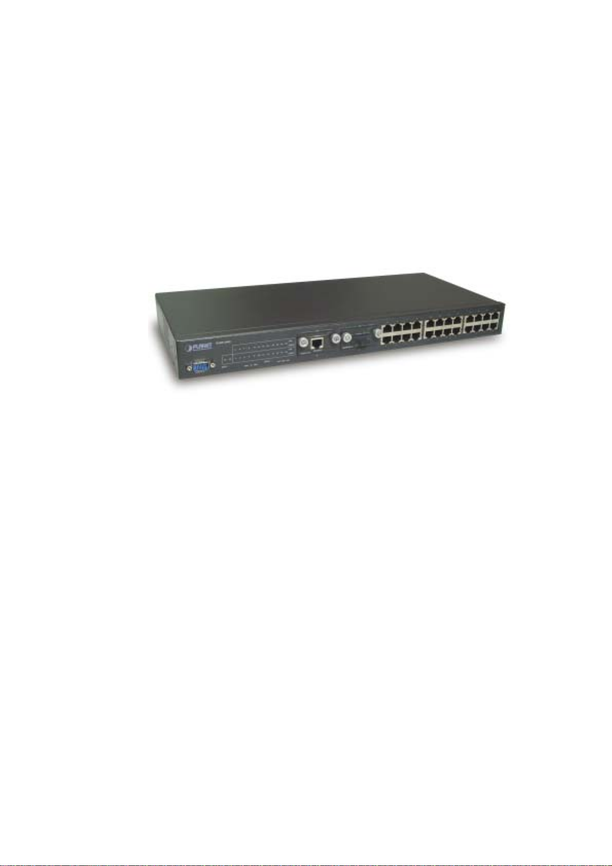
2.1 Front Panel
The Front Panel of the SGSW-2402 Intelligent Switch consists of 24x auto-sensing 10/100Mbps Ethernet
RJ-45 Ports, two optional expansion slots, and Console port. The LED Indicators are also located on the
front panel of the Switch.
SGSW-2402 Switch front panel
2.1.1 LED indicators SGSW-2402
PWR Green Lit on: Power on
Lit off: power off
Link Green Lit on: the connection is good
Lit off: the port is disabled or not detecting a link
Mode:
(could be three kinds of meaning, varies with the Mode button)
ACT Green Lit on: the connection is good.
Blink: The port is receiving or transmitting data
FDX
Green Lit on: the port run at full-duplex
Blink: Half-Duplex/ Collision
Off: Half-duplex or not connected
100 Green Lit on: run at 100Mbps
Lit off: run at 10Mbps or not connected
2.1.2 Buttons indicators
SGSW-2402
RESET When press this button, Switch will reboot
MODE Hold the button for at lease 5 seconds and release, the LED will turns to the
next LED in cycle. (ACT FDXSpeedACT)
4
Page 9

2.2 Rear Panel
The rear panel of the Switch indicates an AC inlet power socket which accepts input power from 100 to
240VAC, 50-60Hz.
SGSW-2402 Switch rear panel
Power Notice:
1. The device is a power-required device, it means, it will not work till it is powered. If your networks
should active all the time, please consider using UPS (Uninterrupted Power Supply) for your device. It
will prevent you from network data loss or network downtime.
2. In some area, installing a surge suppression device may also help to protect your switch from being
damaged by unregulated surge or current to the Switch or the power adapter.
2.3 Hardware Installation
2.3.1 Connecting end node or hub or switch
1. Place the Switch on a smooth surface or fasten the mounting brackets with the provided screws in a
standard 19” rack.
2. Connect switch or PC to one port of the Switch using Category 3/4/5 UTP/STP cabling.
3. Connect another switch or PC to the other port of Switch by following the same process as described in
Step2.
Notice:
Cable distance for Switch
The cable distance between Ethernet Switch and hub/PC should not exceed 100 meter for UTP/STP
cable, 2km for 62.5/125 and 50/125 fiber cable on 100Base-FX module, 220m for 62.5/125 fiber cable
and 500m for 50/125 fiber cable on 1000Base-SX module, 550m for 62.5/125 and 50/125 fiber cable
and 10km for 9/125 fiber cable on 1000Base-LX module.
Make sure the wiring is correct
It can be used Category 3/4/5 cable in 10 Mbps operation. To reliably operate your network at 100Mbps
and 1000Mbps, you must use an Unshielded Twisted-Pair (UTP) Category 5 cable, or better Data
Grade cabling. While a Category 3 or 4 cable may initially seem to work, it will soon cause data loss.
2.3.2 Connecting to Network Backbone or Server
Connect to the Gigabit Ethernet ports with Category 5 copper cable or fiber optic cable for uplinking to a
network backbone or network server. These ports operate at 1000Mbps in full-duplex mode. A valid
connection is indicated when the Link LED is light.
2.4 Terminal Setup
To configure the system, connect a serial cable to a COM port on a PC or notebook computer and to serial
(console) port of the device. The console port of the device is DCE already, so that you can connect the
console port directly through PC without the need of Null Modem.
A terminal program is required to make the software connection to the device. Windows’ Hyper Terminal
program may be a good choice. It can be accessed from the Start menu. Click START, then Programs,
Accessories and then Hyper Terminal.
MS-DOS based terminal program such as PC-PLUS, PROCOMM, can also make the connection with the
device built-in software. The COM port should be configured as:
5
Page 10
♦ Baud : 38400
♦ Parity : None
♦ Data bits : 8
♦ Stop bits : 1
♦ Flow Control: none
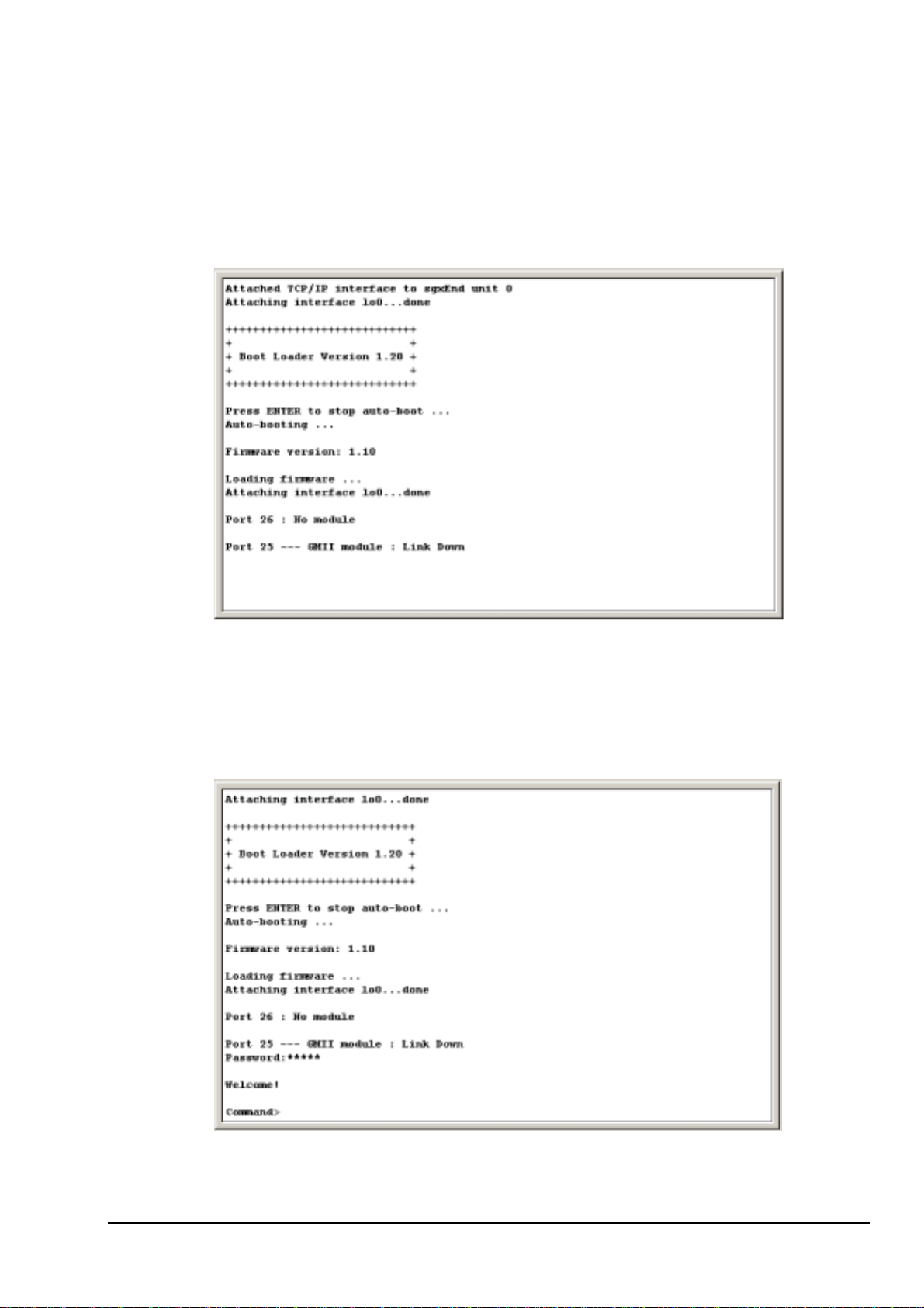
Once the terminal has connected to the device, power on the device. The terminal will display that it is
loading the firmware. Then, the screen as below will show up:
Press “Enter” and input the password. The default password is “admin”.
2.5 IP Configuration
Once log on to the console, the “Command>” prompt will be shown. You can type “help” for all available
commands.
6
Page 11
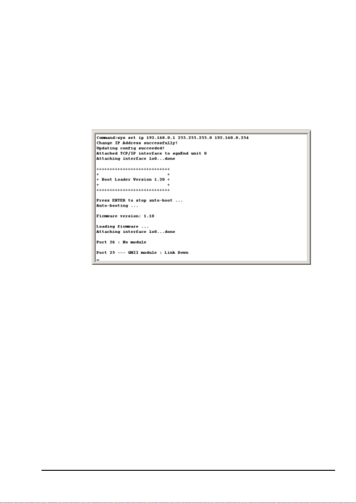
To setup the IP address, please use “sys set ip” command in the following format:
sys set ip <IP Address> <Subnet Mask> <Default Gateway>
For example, to configure the switch with the following IP settings:
IP Address: 192.168.0.2
Subnet Mask: 255.255.255.0
Default Gateway: 192.168.0.254
Press input the following command and press <Enter> button:
sys set ip 192.168.0.2 255.255.255.0 192.168.0.254
If the IP is successful configured, the switch will automatically restart as the following window. You can
then configure the switch through its web interface.
7
Page 12

3.WEB-BASED MANAGEMENT
3.1 Configuration
As well as the menu-driven system configuration program, the agent module provides an embedded
HTTP Web agent. This agent can be accessed by any computer on the network using a standard Web
browser (Internet Explorer 5.0 or above, or Netscape Navigator 4.5 or above).
Using the Web browser management interface you can configure a switch and view statistics to monitor
network activity. The Web interface also provides access to a range of SNMP management functions with
access to the switch's MIB and RMON database.
Prior to accessing the switch from a Web browser, be sure you have first performed the following tasks:
Configure it with a valid IP address, subnet mask, and default gateway using an out-of-band serial
connection.
For Internet Explorer 5.0 or later version user, please check the Java setting below before startup.
1. Click on Tools
2. Pick Internet Options
3. Select the Security tab
4. Select Local Intranet (click on the icon)
5. Click on Sites, click Advanced and add the IP address of the switch to the zone
6. Click on Custom Level
7. Scroll down and set Java Permissions to Custom
8. Press the Java Custom Settings button
9. Select the Edit Permissions tab
10. Set Run Unsigned Content to Enable
11. Press OK for all open dialog windows
NOTE
For IE5.0 or later version, if you can not find the Java option in point 7, please make sure your
Ethernet Explorer is installed with “Microsoft VM” JAVA virtual-machine plug-in.
8
Page 13
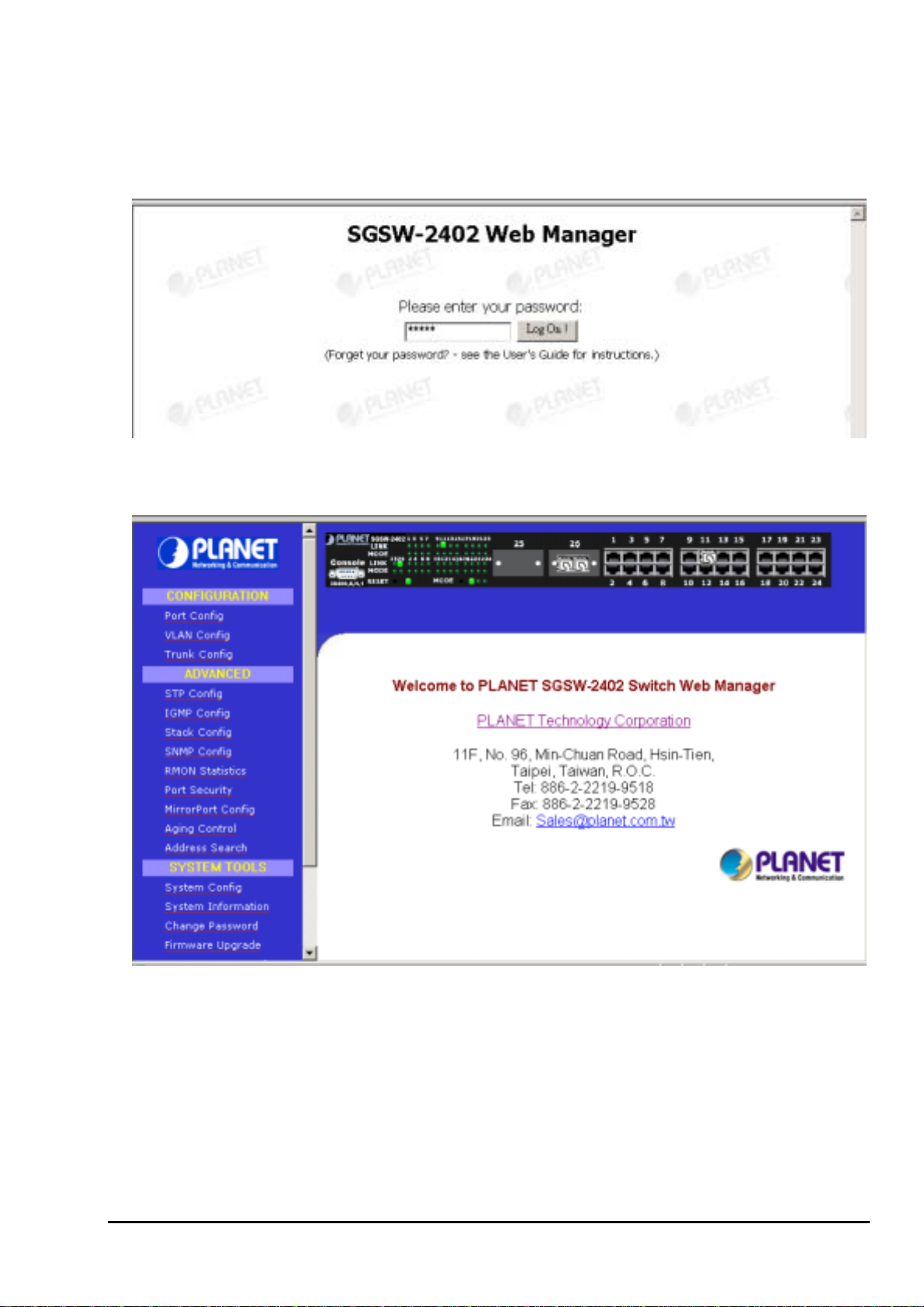
3.2 Web Pages
To access the Web-browser interface you must first enter the password. The default password is "admin"
You will see the following screen comes out on the Web browser program:
Figure 3-1 : Password Screen
After the password is entered you will see the main menu screen.
Figure 3-2: The start up screen of SGSW-2402 Web Page
3.3 Port Config
This section allows you to have an easy access in configuring the ports of the management Switch. Notice
that the “Link state” option indicates “Up”. This shows that the port is connected to the network. It can
either be in “Up” (Connected) or “Down” (No connection) state.
9
Page 14
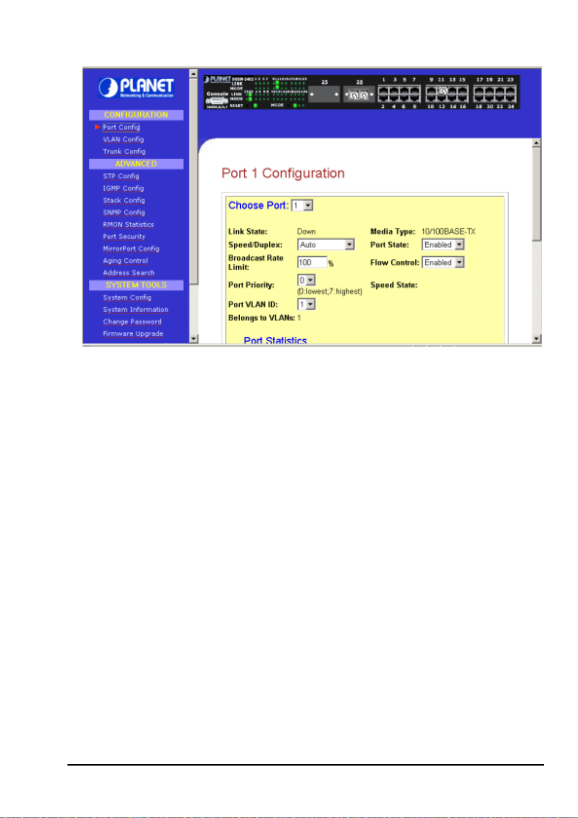
Figure 3-3 The Port Config screen
Choose Port
You can choose a port either by clicking on the picture or by selecting it at the “Choose Port” field.
Speed/ Duplex
Speed/ Duplex is to select the operation mode of chosen port. The options are as:
‘Auto’: Auto negotiation
‘10Mbps HD’: 10 Base-T Half Duplex
‘10Mpbs FD’: 10Base-T Full Duplex
‘100Mpbs HD’: 100Base-TX Half Duplex
‘100Mbps FD’: 100Base-TX Full Duplex
Broadcast Rate Limit
This function sets broadcast limit to the desired rate for the specified port. It controls the reception of
broadcasting packets. The ranging for Broadcast rate limit varies from 0% to 100%. The higher the rate
is, the more broadcast packets can pass through the port. Rate is the percent of the traffic to allow before
throttling. That is, if you configure this value to 10% and current connected speed is 100M, Only 10M
broadcast data can pass through the port.
Port Priority
In a tagged VLAN application, you can specify the VLAN priority to expedite the VLAN traffic. There are
8 levels of priority, namely ‘0’, ‘1’, ‘2’, ‘3’, ‘4’, ‘5’, ‘6’ and ‘7’ in ascending priority.
Port VLAN ID
VLAN ID is the sequence number of a VLAN. The setting of the VLAN ID depends on ‘Belongs to
VLANs’ option. Thus, you should first configure the VLAN table through “VLAN config” option and then
specify this value.
Port State
Port state is for enabling or disabling the switch operation of the chosen port. If it is ‘enabled’, the chosen
port will receive and forward the packets, and learns the respective source MAC Addresses. If it is
‘disable’, the chosen port will not receive or forward any packets or learn source MAC Addresses.
It should be noted that if the cpu port (i.e. the switch port connected to the management workstation) is
disabled, without doubt, the communication link between user and the switch will not proceed further. It
10
Page 15
is recommended to locate the link your PC used before disable the port state.
Flow Control
This feature enables or disables the Flow Control function of the port. Flow control can eliminate frame
loss by "blocking" traffic from end stations or segments connected directly to the switch when its buffers
fill. IEEE 802.3x flow control is used for full duplex. Note that flow control should not be used if a port is
connected to a hub.
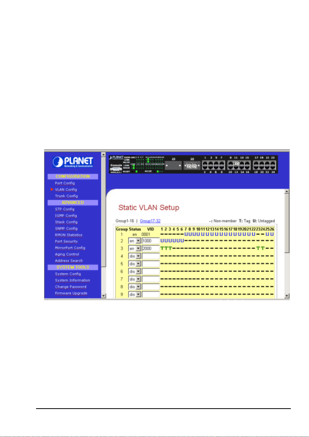
3.4 VLAN Config
The management switch supports Virtual LAN, which logically group the connection into VLANs for traffic
isolation and security purposes. Both tagged and untagged based VLAN are supported with a total
maximum of 32 groups. Each VLAN group only forwards traffic within its member ports. For tagged VLAN,
each port can be a member of more than one VLAN group and it also supports priority with eight levels.
There is also provision for creating an untagged VLAN which support a connection with a legacy untagged
port. The VLAN configuration feature also allows you to build, delete and view tagged / untagged VLAN
groups and setting priority for tagged VLANs. The range of VID starts from 2 to 4094, as
default for Group 1.
VID 001 is the
Figure 3-4 The VLAN config Page
Setup Procedures
Step 1: Decide which Group you want to set for monitoring using mirror port. Click status column for that
particular group and key in the VLAN ID.
Step 2: Next, click on the dashed line’-‘ to select either “T” for Tagged or “U” for Untagged.
Step 3: Hit on “Apply” button after you satisfied with the setup. Click “Save” button to update the latest
configuration.
11
Page 16
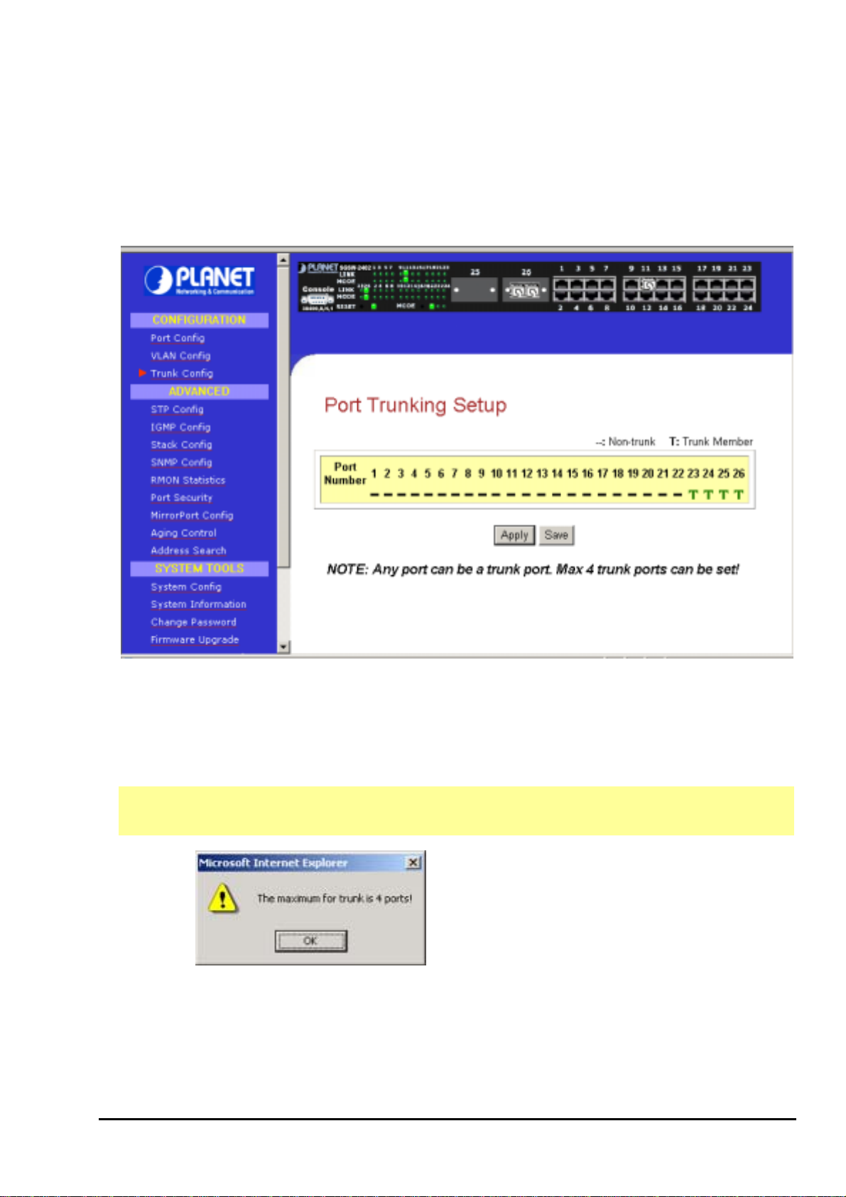
3.5 Trunk config
Port Trunking is the ability to group together several switch ports to increase the bandwidth between the
management switch and other switch. This is an inexpensive method to increase throughput between
switches (or to servers). We define the Port Trunking as the ability to group a set of ports into a single
logical link. The port trunk acts as single link between switches. It doesn’t create a loop even though it is
physically connected as such.
Figure 3-5 The Port Trunk config Page
Port Trunking Setup Procedures
Step 1: You can choose up to 4-port for Trunking by selecting ‘-‘ as “T”
Step 2: Click on “Apply” button to make the configuration effective.
Step 3: Click “Save” button to save the latest setting.
NOTE
Click “OK” button and select the ports again
If you select more than 4 ports for trunking, the following error message will appear:
12
Page 17

3.6 Advanced Configuration
The available options in “Advanced menu” are:
STP Config
IGMP Config
Stack Config The Stack Setup Screen
SNMP Config The SNMP Setup Screen
RMON Statistics Show RMON statistics information
Port Security The Port Security Setup Screen
MirrorPort Config The Mirror Port Setup Screen
Aging Control
Address Search The Address Search Setup Screen
The Spanning Tree Setup Screen
The IGMP Setup Screen
The Aging Control Setup Screen
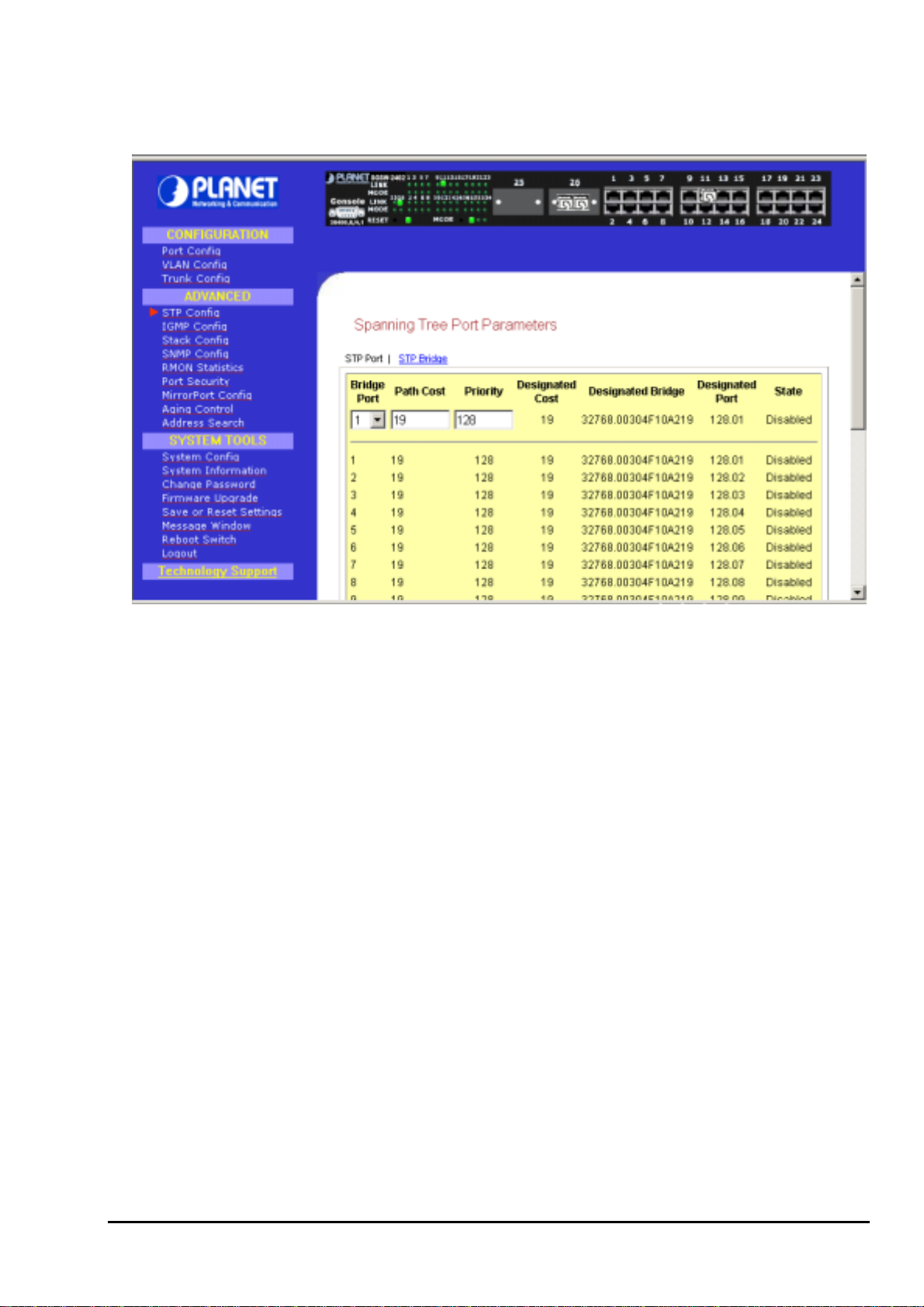
3.7 STP Config
STP Config provides two menu page to configure: STP Port and STP Bridge
3.7.1 STP Port
Bridge Port
This option shows the port of the bridge that connects to the root bridge.
Path Cost
This parameter is used by the STA algorithm to determine the best path between devices. Therefore,
lower values should be assigned to ports attached to faster media, and higher values assigned to
ports with slower media. (Path cost takes precedence over port priority.)
The default and recommended range is: Ethernet: 100 (50~600) Fast Ethernet: 19 (10~60) Gigabit
Ethernet: 4 (3~10). The allowed range is 0 - 65535.
Priority
Defines the priority for the use of a port in the Spanning Tree algorithm. If the path cost for all ports on
a switch are the same, the port with the highest priority (i.e., lowest value) will be configured as an
active link in the Spanning Tree. Where more than one port is assigned the highest priority, the port
with lowest numeric identifier will be enabled. The range is 0 - 255.
Setup Procedures
Step 1: Select any one of the ports, from 1 to 26, to connect to the root bridge.
Step 2: Key in the value for Path Cost.
Step 3: Set the priority level.
13
Page 18
3.7.2 STP Bridge
This page lets you to have a clearer view in Spanning Tree parameters for whole switch.
Figure 3-6 The Spanning Tree Screen
Description of Parameters
STP State
When STP is enabled, it will dynamically detect network looping owing to mis-configuration of the
network topology. The redundant connectors will be disabled to avoid looping of packets. Looping
would often result in flooding of broadcast packets, halting the normal traffic.
Root Priority
Device priority is used in selecting the root device, root port, and designated port. The device with the
highest priority becomes the STA root device. However, if all devices have the same priority, the
device with the lowest MAC address will then become the root device.
Hello Time
The Hello time of the Spanning Tree field shows the number of seconds between the transmissions of
Spanning Tree protocol configuration messages.
Forward Delay
The Forward Delay field shows the number of seconds a port waits before changing from its Spanning
Tree Protocol learning and listening states to the forwarding state. This waiting is necessary so that
other switches on the network ensure no loop is formed before they allow other port to forward
packets.
Max Age
The maximum age time of the Spanning Tree shows the number of seconds the bridge waits without
receiving Spanning Tree Protocol configuration message before attempting a reconfiguration.
Setup Procedures
Step 1: Select Spanning Tree state option, either to enable or disable it.
Step 2: Set Root Priority from 0 s – 65535 s, and Hello Time from 1 s – 10 s.
Step 3: Key in the Forward Delay Time, Maximum Age and Hello Time.
14
Page 19
Step 4: Click “Apply” button and save it if everything is OK.
The screen is divided into two sections. Current Spanning Tree Root section displays the
NOTE
read-only Spanning Tree settings for the current root switch and the parameters this switch is
to use when it becomes the root switch.
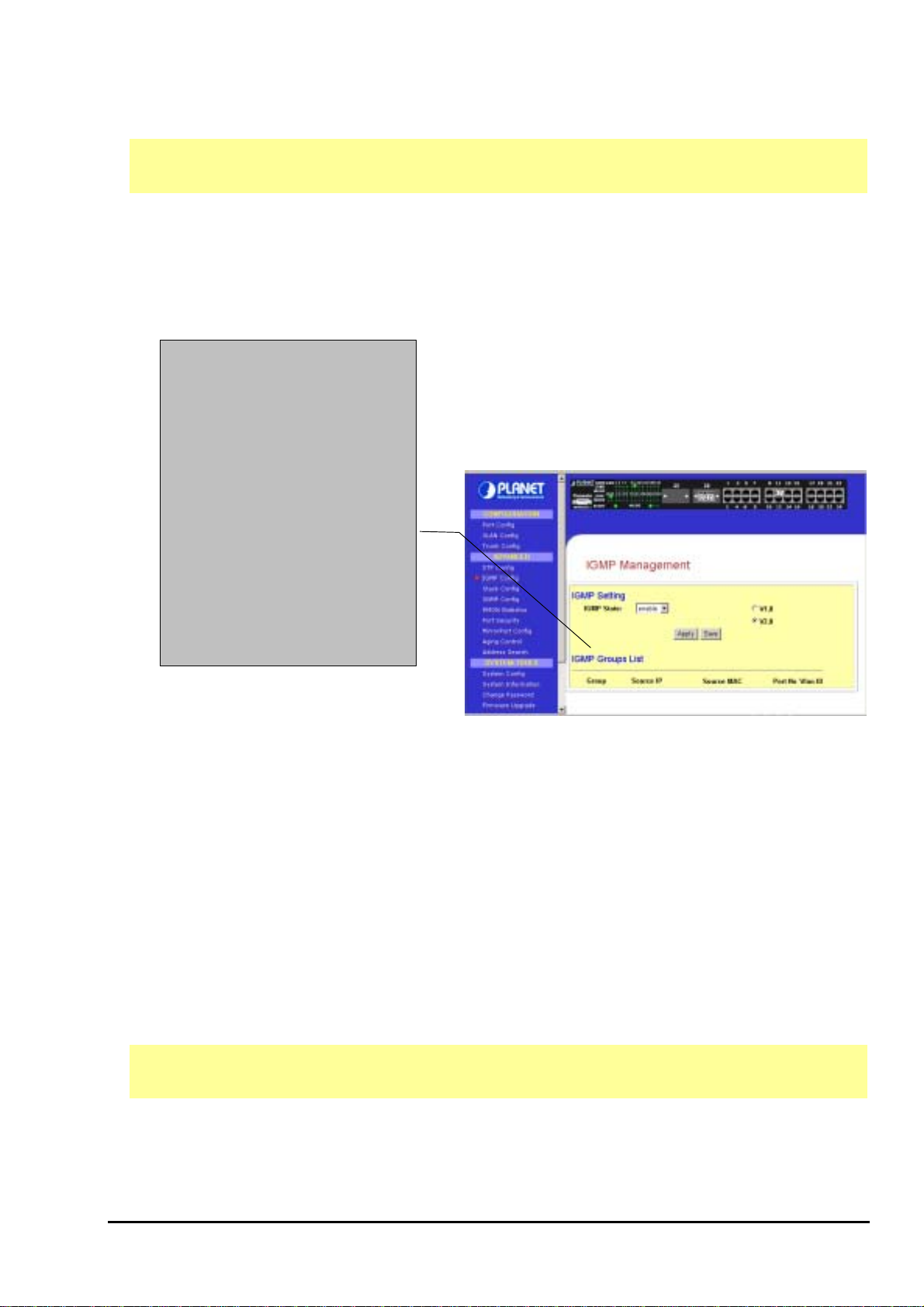
3.8 IGMP
Internet Group Management Protocol (IGMP) is an Internet protocol that provides a way for an
Internet computer to report its multicast group membership to adjacent routers. It allows the
management switch to forward multicast traffic intelligently. The switch "snoops" the IGMP query and
report messages and forwards traffic to only the ports that request the multicast traffic. This prevents
the switch from broadcasting the traffic to all ports and
Host Group Addresses
Host groups are identified by class D IP
addresses, i.e., those with "1110" as their
high-order four bits. Class D IP addresses,
i.e., those with "1111" as their high-order
four bits, are reserved for future addressing
modes.
In Internet standard "dotted decimal"
notation, host group addresses range from
224.0.0.0 to 239.255.255.255. The address
224.0.0.0 is guaranteed not to be assigned
to any group, and 224.0.0.1 is assigned to
the permanent group of all IP hosts
(including gateways). This is used to
address all multicast hosts on the directly
connected network. There is no multicast
address (or any other IP address) for all
hosts on the total Internet. The addresses of
other well-known, permanent groups are to
be published in "Assigned Numbers".
possibly affecting network performance.
The membership of a host group is dynamic - hosts may join
and leave groups at any time. There is no restriction on the
location or number of members in a host group. A host may
be a member of more than one group at a time. A host need
not be a member of a group to send datagrams to it.
Figure 3-7 The IGMP Screen page
3.8.1 IGMP Management
To activate IGMP function,
Step 1: Select “enabled” in the IGMP state field.
Step 2: Click on the radio button to select the version for IGMP.
Step 3: Hit on the “Apply” button and save your setting.
3.8.2 Definition on IGMP v1.0 and v2.0
For IGMP v1.0,
The Internet Group Management Protocol (IGMP v1.0) is used by IP hosts to report their host group
memberships to any immediately neighboring multicast routers. IGMP is an asymmetric protocol and
is specified here from the point of view of a host, rather than a multicast router.
NOTE
For IGMP v2.0,
IGMP v2.0 allows group membership termination to be quickly reported to the routing protocol, which is
important for high-bandwidth multicast groups and/or subnets with highly volatile group membership.
IGMPv1 has no leave mechanism. If a host no longer wants to receive the traffic, it simply
quits. If it is the last, the router will not have any answers to its query and will delete the GDA
for that subnet.
15
Page 20

Multicast routers use IGMP v2.0 to learn which groups have members on each of their attached
physical networks. A multicast router keeps a list of multicast group memberships for each attached
network, and a timer for each membership. "Multicast group memberships" means the presence of at
least one member of a multicast group on a given attached network, not a list of all of the members.
When a host receives a General Query, it sets delay timers for each group (excluding the all-systems
group) of which it is a member on the interface from which it received the query.
When a router receives a Report, it adds the group being reported to the list of multicast group
memberships on the network on which it received the Report and sets the timer for the membership to
the [Group Membership Interval].
When a host joins a multicast group, it should immediately transmit an unsolicited Version 2
Membership Report for that group, in case it is the first member of that group on the network
When a host leaves a multicast group, if it was the last host to reply to a Query with a Membership Report
for that group, it SHOULD send a Leave Group message to the all-routers multicast group.
3.9 Stack
Stacking function is convenient for administrator to manage multiple switches by single IP.
Basically, you got to have min. 2 units,
Step 1: linking the switches by one category 5 or fiber cable.
Step 2: Choose either one management switch as Master switch, key in its IP number
(ex:203.70.249.152).
Step 3: Choose “Stack Config”.
Step 4: Choose “enable” of Stacking State, and “Save”.
Figure 3-8 The Stack screen page
16
Page 21

Figure 3-9 The Stack screen page
Step 5: enter another unit management switch IP (ex:203.70.249.154) as Slave switch.
Step 6: choose “Stack Config”
Step 7: choose “Enable” of Stacking State, and “Save”.
Figure 3-10 The Stack screen page
17
Page 22

NOTE
You can key in Master IP (ex:203.70.249.152), and choose “Stack Config”, then all the stack member list
will be displayed . You can then choose the switch you want to configure from the “Select switch to view”
list.
NOTE
Slave switch IP will be covered by Master one, and disappear temporarily. The slave IP
address can be the same as Master IP address. Thus, if master switch is malfunction, you
can still access the other switch by same IP address.
If you have difficulty on selecting another switch, you may be connecting to the slave switch’s
web, please close the browser window, use the “arp –d * ” DOS command to clear the ARP
table and then reopen the web.
Figure 3-11 The Stack screen page
3.10 SNMP
The management switch provides Simple Network Management Protocol (SNMP) over the UDP/IP
transport protocol as defined in RFC 1517 for network management applications.
To control the access of the system, a list of community entries is defined. Each community entry consists
of a community string and its access privilege. The Access privilege is either “Read Only” or “Read-Write”.
Only SNMP messages with correct community string and allowable operation are responded by the
system. The community list is configurable by all management operations. Only SNMP community with
“Read-Write” can view the whole list and make modifications. A “Read Only” community can only see its
own community entry.
NOTE
Trap messages are generated to report system events spontaneously as defined in RFC 1215. The
system can generate traps defined in the MIB it supports.
A list of “Trap Receivers” is defined in management as the target of each trap message. A Trap Receiver
In a stack environment, for master switch to know which switch you want to view and set by
SNMP, either the switches’ IP or community name must be different. Thus, if you have
stacked several switches by single IP, their community name must be different.
18
Page 23

is a network node that deserves the trap message sent by management switch. A Trap Receiver entry
contains the IP address of the node and a community string that is included in the trap message. When an
event arises that requires a trap message to be sent, it is sent to every node listed in the Trap Receiver.
NOTE
If you are configuring slave switch’s SNMP settings, please reboot the switch after making
any configuration.
Figure 3-12 The SNMP screen
3.11 RMON Statistics
This function allows to display all port’s RMON Statistics
19
Page 24

Figure 3-13. RMON Statistics page
3.12 Port Security
Of all 26 ports, some of the end nodes may need to assign to the specific port. In order to fulfill this act,
MAC Address should be added to that particular port. This is to ban other users from using the static port.
A port can accommodate up to 20 MAC Addresses.
20
Page 25

Figure 3-14. Port Security page
3.12.1 Setting Up Procedures
Step 1: Select the port that you want to add in the MAC Address
Step 2: Key in the MAC Address in the field provided, e.g. 00-80-40-E8-85-12, and click “Add” button
The system will then add in the New MAC Address into the listing on the right side of the screen.
3.12.2 Delete MAC Address
If you want to delete MAC Address(es), simply follow the procedures shown below:
For deleting individual MAC Address
Step 1: Select a MAC Address and clink on "Del ->" button.
The system will prompt you to confirm your action:
Step 2: Choose “OK” button to confirm.
The particular MAC Address will be successfully deleted!
For deleting ALL MAC Addresses
Step 1: Click on "Delete All" button and the system will again prompt you the message as shown as
above.
Step 2: Choose "OK" button to confirm.
All MAC Addresses will be deleted immediately!
3.13 Mirror Port
3.13.1 Using Mirror Port to Monitor Traffic
This function allows you to set up a ‘mirror’ port of any specified port(s) or VLAN, such that you can
monitor the traffics of the monitored port(s) or VLAN without intervening them. In effect, the traffics on the
monitored port(s) VLAN are replicated on the mirror port that you can use a protocol analyzer to analyze
the traffic for specific problem.
21
Page 26

Figure 3-15. Mirror Port Setup screen
3.13.2 Setup Procedures
Step 1: Select one Mirror Port.
Step 2: Click on the dashed line ‘-‘ on that particular port if you wan to select it as a Mirrored Member (T).
Step 3: Hit on “Apply” button after you are satisfied with the setup. Click “Save” button to update the latest
configuration.
3.14 Aging Control
Aging Control is for the aging of address entries in the switch’s forwarding table. If the aging control is
enabled, a learned address entry (not included the static entry) will be removed from the forwarding table
if there is no update within a pre-determined period (1 ~ 128 x 5 seconds). It is useful because the
resource of the forwarding table is limited. Enabling the aging control will not influence packets forwarding,
for that the packet is forwarded to all other ports when the destination MAC address cannot to found in the
forwarding table. If the aging control is disabled, all address entries will not be removes.
22
Page 27

Figure 3-16 Aging Control screen
Aging Control Configuration Procedures
Step 1: Select “Enable” from the Aging Control option.
Step 2: Enter an integer in the entry, choosing from the range of 1 to 128, if the aging control is enabled.
If the aging control is disabled, this step can be skipped.
3.15 Address Search
Host Search is for searching a host by IP or MAC address on the whole switch, and getting the port
number to switch the host is connected. It is useful while configuring the VLAN. With this function, you can
easily detect the port at which a host is connected to and have an idea about which ports should be
included in a VLAN.
23
Page 28

Figure 3-17 The Host search page
3.15.1 Host Searching Procedures
Step 1: Enter the IP Address of the host.
Step 2: Click on “Search” button.
The result will displayed as shown:
If the system can not find the Host Address the following GUI will appear:
24
Page 29

3.15.2 MAC Address Search
This feature helps to look for the particular MAC Address stated in the field, which provides a useful way
while configuring the VLAN. The system will search through the device for the port’s ownership of that
particular PC.
Figure 3-18 The MAC Address search screen
MAC Address Search Procedures
Step 1: Enter MAC Address in the field provided.
Step 2: Click on “Search” button.
If MAC Address was found by the system, the result will appear as:
25
Page 30

But, if the system cannot find any matching MAC Address, the following search result will appear:
3.16 System Tools
The available options in “System Tools” are:
System Config
System Information The IGMP Setup Screen
Change Password The Stack Setup Screen
The Spanning Tree Setup Screen
Firmware Upgrade The SNMP Setup Screen
Save or Reset Settings The Port Security Setup Screen
Message Window The Mirror Port Setup Screen
Reboot Switch The Aging Control Setup Screen
Logout The Address Search Setup Screen
3.17 System Config
This page allow configuring the basic switch information and IP address. The configuration procedure is:
Step 1: Give a description for the system name and location of this switch.
Step 2: Key in the contact information and describe the product of the switch.
Step 3: Enter the IP address and Subnet Mask.
Step 4: Click “Apply” button and save the setting by hitting “Save” button.
Upon making amendments on this page, the screen will appear a message, “Reboot the switch?”. Click on
the ‘Yes’ button to take effect on the changes.
26
Page 31

Click on “Logon” button again if you still need to access to the management switch web page. This cannot
apply to the changing of IP Address! Please refer to the following notes for details.
Please note that after changing IP Address of the device, the system will not lead you
NOTE
to log in the management switch web page after you have clicked “Logon” button.
Instead, a page error will display on the screen state that “The page cannot be
displayed”. Don’t worry! What you need to do is to enter your NEW IP Address to login
to the web page
Figure 3-19 System Config screen
3.18 System Information
System Information displays the necessary data about the management system.
27
Page 32

Figure 3-20 The System Information
3.19 Change Password
This option allows you to amend the current password.
28
Page 33

Figure 3-21 The change password screen
Changing password procedure
Step 1: Type in your current password.
Step 2: Enter your new password.
Step 3: Enter the new password again for confirmation.
Step 4: Click on “Changing Password” button to active the new setting.
If your password is keyed correctly, the system will reply you with a system message, stating that your
password has been changed successfully.
However, if wrong password is entered any of the error messages shown below will appear:
29
Page 34

Hit “return” button and re-enter the password correctly.
3.20 Firmware Upgrade
You can simply download the newer version Firmware from www.planet.com.tw Here, you will find links
that allows easy access for upgrading of future released of updated firmware.
Figure 3-22 The Firmware Upgrade page
30
Page 35

To check your current firmware version, click “Knowing the System Information” as mentioned in 3.18
System Information.
After downloading the firmware, saved it into your hard disk.
Upgrade Firmware Procedure
Step 1: Click “Browse” button to select the file where you have just saved and ‘Choose file’ dialog box will
appear, prompting you to select the file to upgrade the firmware.
Step 2: Click “Upgrade” button to start replacing the latest Firmware revision.
The system will prompt you reboot the management switch.
Step 3: Click “Yes” button to restart the device.
31
Page 36

Step 4: Log on the web site after about 60 seconds if you still need to do some configuration on the
management switch.
NOTE
On the other hand, if you choose the wrong file, a system message will appear:
If you are using the same or older version of the firmware, the system will prompt you whether
or not to use the firmware. See the GUI shown below:
3.21 Save & Reboot
The Save and Reset Settings allow you to execute the amendments or reset to the default setting of
configuration.
32
Page 37

3.21.1 Save
By click the “Save” button, you will save all the changes made in the management switch. You need to
reboot the switch to ensure that the profile is updated correctly.
3.21.2 Backup
This option allows you to backup the switch’s configuration into a file.
To create a backup configuration,
Step 1: Click on the “Backup” button and the system will prompt you to either open the file or save it to
disk.
Step 2: Select the radio button to “Save the file to disk” and click “OK” button.
33
Page 38

The system will then prompt you to save switch.cfg to a destination.
Step 3: Select a folder that you want to save the file and click “SAVE” button to proceed.
Step 4: After downloading process has completed, the following GUI will appear. Click “Close” button if
you do not want to view the downloaded file.
34
Page 39

3.21.3 Restore
This option allows you to restore the old configuration from your backup file.
Step 1: Click “Browse” button and select the file that you want the system to restore back the
configuration.
Step 2: Click “Restore” button to start the process.
35
Page 40

The system will request you to reboot the switch.
Step 3: Click “Yes” button to restart the switch.
Step 4: Wait for about 60 seconds and the system will automatically return to the Login Web page,
prompting you to enter password again.
3.21.4 Clear and Reset
By clicking this option, you will restore the management switch to factory defaults. And you will have to
re-enter all the configuration information to your network.
To Clear or reset the setting,
Step 1: Click on “Clear and Reset” button. The system will prompt you to choose whether you really want
to reset the configuration data.
Step 2: Click “Yes” button to proceed and the system will automatically reset the IP address to factory
default, which is http://192.168.100.128
36
Page 41

Step 3: Click “Logon” button if you want to make some more changes.
3.22 Message Windows
Display Switch system message.
Figure 3-23 The Message Window page
37
Page 42

3.23 Reboot Switch
Rebooting the management switch is required after changes are made in the configuration or setting.
Figure 3-24 The Reboot Switch page
Click “Yes” to reboot the switch. The system will prompt you to logon again after about 60 seconds to see
the effect.
3.24 Logout
With the web browser, logging out is as easy as ABC. By clicking “Logout” button, you will get a logout GUI
as shown below. If you need to access to the Web Page again, you just need to click “Logon” button. This
is true only if you have not changed the default factory settings for the IP address of your switch.
Alternatively, you can log in again into the web-based browser via http://192.168.100.128
address, which you have assigned to the switch.
or the new IP
38
Page 43

NOTE
Figure 3-25 The Logout page
If you changed a new IP Address for the management switch, the system will NOT
automatically changed to the new IP address after you click on the “Logon” button.
39
Page 44

4 CONSOLE INTERFACE
4.1 CONNECT TO PC
To configure the system through its console interface, connect a serial cable to a COM port on a PC or
notebook computer and to serial (console) port of the device. The console port of the device is DCE
already, so that you can connect the console port directly through PC without the need of Null Modem.
A terminal program is required to make the software connection to the device. Windows’ Hyper Terminal
program may be a good choice. It can be accessed from the Start menu. Click START, then Programs,
Accessories and then Hyper Terminal.
MS-DOS based terminal program such as PC-PLUS, PROCOMM, can also make the connection with the
device built-in software. The COM port should be configured as:
♦ Baud : 38400
♦ Parity : None
♦ Data bits : 8
♦ Stop bits : 1
♦ Flow Control: none
For example, if using hyperterminal, the configuration should be:
40
Page 45

4.2 Logging on to the Switch
To log on to the Switch:
1. At the screen prompt:
Figure 4-1 SGSW-2402 Console Login on Screen
Enter the console interface factory default console password (admin) or user-defined password if you
changed the default password using the instructions in Section 4.2.9 . The Switch Management prompt in
Figure 4-2 appears:
Figure 4-2 SGSW-2402 Console Main Screen
41
Page 46

Please type “Help” on the command line, the main menu displays all the system command usage that are
available as below:
Figure 4-3 SGSW-2402 Console command Screen
SYS--SYSTEM MANAGEMENT COMMANDS
sys show info
sys show ip
sys show ethernet address
sys set ip <IP Address> <Subnet Mask> <Default Gateway>
sys set name "string"
sys set contact "string"
sys set location "string"
sys set password
sys set link_info <on|off>
sys reset system
sys reset config
sys save config
LOGOUT--EXIT MANAGEMENT COMMANDS
Logout
PORT--PORT MANAGEMENT COMMANDS
port show
port set enable <port number> [-h|-f] [-10|-100|-1000] [-A]
port set disable <port number>
port set flw <port number> <on|off>
port set bck <port number> <on|off>
port set pri <port number> <-p priority>
port set vid <port number> <-v vid>
42
Page 47

VLAN--VLAN MANAGEMENT COMMANDS
vlan show
vlan build <vid> <-u untags> <-t tags> <-p priority>
vlan delete <vid>
vlan set pri <vid> <-p priority>
TRUNK--TRUNK MANAGEMENT COMMANDS
trunk show
trunk set <port1> [port2] [port3] [port4]
STP--STP MANAGEMENT COMMANDS
stp [on|off]
SNMP--SNMP MANAGEMENT COMMANDS
SNMP [ON|OFF
]
STACK--STACK MANAGEMENT COMMANDS
stack [on|off]
4.2.1. sys--System Management Commands
This menu contains system parameters to display and configure the switch to your network. Menu items
are:
Figure 4-4 SGSW-2402 sys command Screen
43
Page 48

4.2.2 sys show info
This command display the system information of SGSW-2402.
Figure 4-5 SGSW-2402 system information Screen
4.2.3. sys show IP
This command display the network information of SGSW-2402.
Figure 4-6 SGSW-2402 network information Screen
44
Page 49

4.2.4. sys show Ethernet address
This command display the MAC address of SGSW-2402.
Figure 4-7 SGSW-2402 Mac address information Screen
4.2.5. sys set ip <IP Address> <Subnet Mask> <Default Gateway>
This command allow to set the IP address, Subnet Mask, Gateway of SGSW-2402.
Figure 4-8 SGSW-2402 network setting Screen
45
Page 50

4.2.6. sys set name "string"
This commands allow to set the system name of SGSW-2402.
Figure 4-9 SGSW-2402 system name setting Screen
4.2.7. sys set contact "string"
This command allow to set system administrator name of SGSW-2402.
Figure 4-10 SGSW-2402 system administrator name setting Screen
46
Page 51

4.2.8. sys set location "string"
This command allow to set the location of SGSW-2402.
Figure 4-11 SGSW-2402 system location setting Screen
4.2.9. sys set password
This command allow to set the password of SGSW-2402.
NOTE
The new password should be an alphanumeric string of size 6 to 15, starting with a letter
Figure 4-12 SGSW-2402 password setting Screen
47
Page 52

4.2.10. sys set link_info <on|off>
This command is used to report the link status of the ports. Once it is enabled, it will prompt the port status
on the console. Or if you disable it, it will not prompt the port status any more.
Figure 4-13 SGSW-2402 system link report setting Screen
4.2.11. sys reset system
This command will reboot the SGSW-2402.
Figure 4-14 SGSW-2402 reset system Screen
48
Page 53

4.2.12. sys reset config
This command will reboot and reset to the default mode of SGSW-2402.
Figure 4-15 SGSW-2402 reset config Screen
4.2.13. sys save config
This command will save the current configure of SGSW-2402.
Figure 4-16 SGSW-2402 save config Screen
49
Page 54

4.2.14. logout
This command will logout the SGSW-2402.
Figure 4-17 SGSW-2402 logout Screen
4.2.15. port--Port Management Commands
This menu contains system parameters to display and configure the port of the switch Menu items are:
Figure 4-18 SGSW-2402 port command Screen
50
Page 55

4.2.16. port show
This command display port status of each port.
Figure 4-19 SGSW-2402 port statistics Screen
4.2.17. port set enable <port number> [-h|-f] [-10|-100|-1000] [-A]
This command allow to set the speed duplex mode of each port
Figure 4-20 SGSW-2402 port set enable Screen
51
Page 56

4.2.18. port set disable <port number>
This command allow to disable each port
Figure 4-21 SGSW-2402 port disable Screen
4.2.19. port set flw <port number> <on|off>
This command allow to disable or enable flow control on each port
Figure 4-22 SGSW-2402 flow control disable /enable Screen
4.2.20. port set bck <port number> <on|off>
This command allow to disable / enable Back Pressure on each port
Figure 4-23 SGSW-2402 Back Pressure disable /enable Screen
52
Page 57

4.2.21. port set pri <port number> <-p priority>
This command allow to set the priority on each port
Figure 4-24 SGSW-2402 port priority Screen
4.2.22. port set vid <port number> <-v vid>
This command allow to set the VLAN group and assign VLAN ID.
Figure 4-25 SGSW-2402 port VLAN ID Screen
53
Page 58

4.2.23. vlan--VLAN Management Commands
This menu contains system parameters to display and configure the VLAN of SGSW-2402 . Menu items
are:
Figure 4-25 SGSW-2402 VLAN command Screen
4.2.24. vlan show
This command display VLAN states
Figure 4-26 SGSW-2402 VLAN statics Screen
54
Page 59

4.2.25. vlan build <vid> <-u untags> <-t tags> <-p priority>
This command allow to create VLAN group and assign VLAN tag and untagged
Figure 4-27 SGSW-2402 VLAN setting Screen
4.2.26. vlan delete <vid>
This command allow to delete VLAN group.
Figure 4-28 SGSW-2402 VLAN delete Screen
4.2.27. vlan set pri <vid> <-p priority>
This command allow to set VLAN priority.
Figure 4-28 SGSW-2402 VLAN priority Screen
55
Page 60

4.2.28. trunk--TRUNK Management Commands
This menu contains system parameters to display and configure the trunk of this switch. Menu items are:
Figure 4-29 SGSW-2402 Trunk command Screen
4.2.29. trunk show
This command displayed the Trunk status
Figure 4-30 SGSW-2402 Trunk status Screen
56
Page 61

4.2.30. trunk set <port1> [port2] [port3] [port4]
This command allow to set trunk port
Figure 4-31 SGSW-2402 Trunk group setting Screen
4.2.31. stp--STP Management Commands
This command allow to disable / enable STP function on SGSW-2402
Figure 4-31 SGSW-2402 disable / enable STP Screen
4.2.32. snmp--SNMP Management Commands
This command allow to disable / enable SNMP function on SGSW-2402
Figure 4-32 SGSW-2402 disable / enable SNMP Screen
57
Page 62

4.2.33. stack--STACK Management Commands
This command allow to disable / enable Stack function on SGSW-2402
Figure 4-33 SGSW-2402 disable / enable Stack Screen
58
Page 63
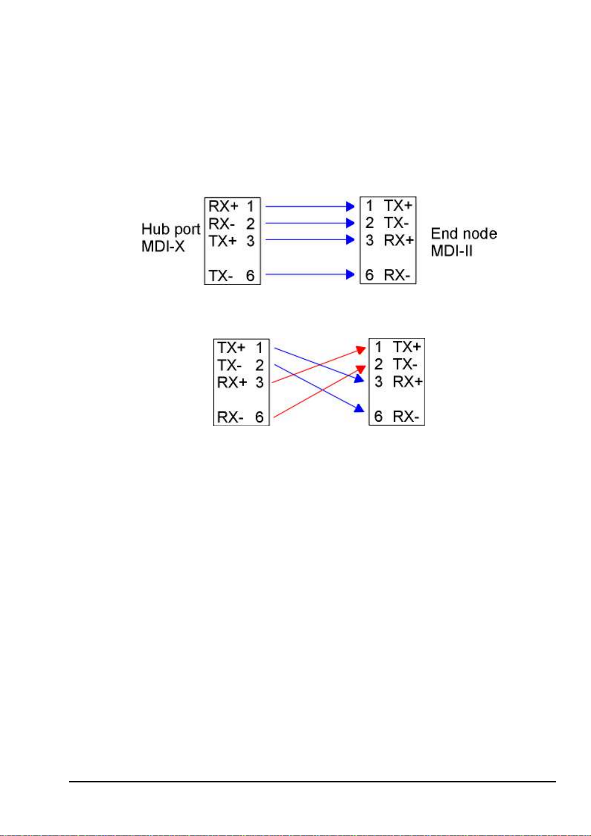
APPENDIX A NETWORKING CONNECTION
When attaching an end-station to the device, a standard straight-through CAT5 cable may be used, even
when the end-station is attached via a patch panel. However, when attaching another switch or attaching
workstations via hubs, a crossover cable will need to be used. Please see the following wire diagrams for
examples of both cable types.
Figure A-1: Straight-Through Cable
Figure A-2: Crossover Cable
59
 Loading...