

Page 1

SGSD-1022 / SGSD-1022P
User’s Manual of SGSD-1022 / SGSD-1022P
SGSW-2840 / SGSW-2840P
User’s Manual
SGSW-2840 / SGSW-2840P
Layer 2 Managed Switches
1
Page 2

User’s Manual of SGSD-1022 / SGSD-1022P
SGSW-2840 / SGSW-2840P
Trademarks
Copyright © PLANET Technology Corp. 2008.
Contents subject to which revision without prior notice.
PLANET is a registered trademark of PLANET Technology Corp. All other trademarks belong to their respective owners.
Disclaimer
PLANET Technology does not warrant that the hardware will work properly in all environments and applications, and makes no
warranty and representation, either implied or expressed, with respect to the quality, performance, merchantability, or fitness for
a particular purpose. PLANET has made every effort to ensure that this User's Manual is accurate; PLANET disclaims liability
for any inaccuracies or omissions that may have occurred.
Information in this User's Manual is subject to change without notice and does not represent a commitment on the part of
PLANET. PLANET assumes no responsibility for any inaccuracies that may be contained in this User's Manual. PLANET makes
no commitment to update or keep current the information in this User's Manual, and reserves the right to make improvements to
this User's Manual and/or to the products described in this User's Manual, at any time without notice.
If you find information in this manual that is incorrect, misleading, or incomplete, we would appreciate your comments and
suggestions.
FCC Warning
This equipment has been tested and found to comply with the limits for a Class A digital device, pursuant to Part 15 of the FCC
Rules. These limits are designed to provide reasonable protection against harmful interference when the equipment is operated
in a commercial environment. This equipment generates, uses, and can radiate radio frequency energy and, if not installed and
used in accordance with the Instruction manual, may cause harmful interference to radio communications. Operation of this
equipment in a residential area is likely to cause harmful interference in which case the user will be required to correct the
interference at whose own expense.
CE Mark Warning
This is a Class A product. In a domestic environment, this product may cause radio interference, in which case the user may be
required to take adequate measures.
WEEE Warning
To avoid the potential effects on the environment and human health as a result of the presence of
hazardous substances in electrical and electronic equipment, end users of electrical and electronic
equipment should understand the meaning of the crossed-out wheeled bin symbol. Do not dispose of
WEEE as unsorted municipal waste and have to collect such WEEE separately.
Revision
PLANET 8 / 24-Port 10/100Mbps with 2 / 4 Gigabit TP / SFP Combo Managed Security Switch User's Manual
FOR MODELS: SGSD-1022 / SGSD-1022P / SGSW-2840 / SGSW-2840P
REVISION: 1.0 (AUGUEST.2008)
Part No: EM-SGSD-SGSW (2080-A34050-000)
2
Page 3

User’s Manual of SGSD-1022 / SGSD-1022P
SGSW-2840 / SGSW-2840P
TABLE OF CONETNTS
1. INTRODUTION ....................................................................................................................23
1.1 Packet Contents .........................................................................................................................................23
1.2 Product Description...................................................................................................................................23
1.3 How to Use This Manual............................................................................................................................25
1.4 Product Features........................................................................................................................................25
1.5 Product Specification ................................................................................................................................28
2. INSTALLATION ................................................................................................................... 30
2.1 Hardware Description................................................................................................................................30
2.1.1 Switch Front Panel ..............................................................................................................................................30
2.1.2 LED Indications ...................................................................................................................................................31
2.1.3 Switch Rear Panel............................................................................................................................................... 35
2.2 Install the Switch........................................................................................................................................38
2.2.1 Desktop Installation .............................................................................................................................................38
2.2.2 Rack Mounting.....................................................................................................................................................39
2.2.3 Installing the SFP transceiver..............................................................................................................................41
3. SWITCH MANAGEMENT....................................................................................................43
3.1 Requirements..............................................................................................................................................43
3.2 Management Access Overview.................................................................................................................44
3.3 Administration Console.............................................................................................................................44
3.4 Web Management.......................................................................................................................................46
3.5 SNMP-Based Network Management.........................................................................................................46
3.6 Protocols.....................................................................................................................................................47
3.6.1 Virtual Terminal Protocols....................................................................................................................................47
3.6.2 SNMP Protocol....................................................................................................................................................47
3.6.3 Management Architecture....................................................................................................................................47
4. WEB CONFIGURATION......................................................................................................48
4.1 Main WEB PAGE.........................................................................................................................................51
3
Page 4

User’s Manual of SGSD-1022 / SGSD-1022P
SGSW-2840 / SGSW-2840P
4.2 System.........................................................................................................................................................54
4.2.1 System Information..............................................................................................................................................55
4.2.2 Switch Information...............................................................................................................................................56
4.2.3 Bridge Extension Configuration...........................................................................................................................57
4.2.4 IP Configuration...................................................................................................................................................58
4.2.5 Jumbo Frames..................................................................................................................................................... 60
4.2.6 File Management.................................................................................................................................................60
4.2.6.1 Copy Operation.......................................................................................................................................60
4.2.6.2 Delete .....................................................................................................................................................66
4.2.6.3 Set Startup..............................................................................................................................................66
4.2.7 Line......................................................................................................................................................................68
4.2.7.1 Console Port Settings................................................................................................................................68
4.2.7.2 Telnet Settings...........................................................................................................................................70
4.2.8 Log ......................................................................................................................................................................71
4.2.8.1 System Log Configuration.........................................................................................................................71
4.2.8.2 Remote Log Configuration.........................................................................................................................73
4.2.8.3 Displaying Log Messages.......................................................................................................................... 74
4.2.8.4 SMTP E-Mail Alert.....................................................................................................................................75
4.2.9 UPNP...................................................................................................................................................................77
UPnP Configuration...............................................................................................................................................77
4.2.10 Reset.................................................................................................................................................................78
4.2.11 SNTP.................................................................................................................................................................79
4.2.11.1 SNTP Configuration.................................................................................................................................79
4.2.11.2 Clock Time Zone......................................................................................................................................80
4.2.12 LLDP..................................................................................................................................................................81
4.2.12.1 LLDP Configuration.................................................................................................................................81
4.2.12.2 LLDP Port Configuration..........................................................................................................................83
4.2.12.3 LLDP Trunk Configuration.......................................................................................................................86
4.2.12.4 LLDP Local Device Information...............................................................................................................89
4.2.12.5 Remote Port Information .........................................................................................................................91
4.2.12.6 LLDP Remote Information Detail.............................................................................................................92
4.2.12.7 LLDP Device Statistics............................................................................................................................94
4.2.12.8 LLDP Device Statistics Details.................................................................................................................95
4.3 Simple Network Management Protocol....................................................................................................96
4.3.1 SNMP Agent Status.............................................................................................................................................97
4.3.2 SNMP Configuration............................................................................................................................................97
4.3.2.1 SNMP Community.....................................................................................................................................97
4.3.2.2 SNMP Trap Management..........................................................................................................................98
4.3.3 SNMPv3 ............................................................................................................................................................101
4.3.3.1 SNMPv3 Engine ID..................................................................................................................................101
4
Page 5

User’s Manual of SGSD-1022 / SGSD-1022P
SGSW-2840 / SGSW-2840P
4.3.3.2 SNMPv3 Remote Engine ID....................................................................................................................102
4.3.3.3 SNMPv3 Users........................................................................................................................................103
4.3.3.4 SNMPv3 Remote Users ..........................................................................................................................106
4.3.3.5 SNMPv3 Groups......................................................................................................................................108
4.3.3.6 SNMPv3 View..........................................................................................................................................111
4.4 Port Management .....................................................................................................................................113
4.4.1 Port Information.................................................................................................................................................113
4.4.2 Port Configuration..............................................................................................................................................115
4.4.3 Port Broadcast Control ......................................................................................................................................117
4.4.4 Port Mirroring.....................................................................................................................................................119
4.4.4.1 Mirror Port Configuration.........................................................................................................................119
4.4.5 Rate Limit ..........................................................................................................................................................122
4.4.5.1 Input Rate Limit Port Configuration..........................................................................................................122
4.4.5.2 Output Rate Limit Port Configuration.......................................................................................................123
4.4.6 Port Statistics.....................................................................................................................................................124
4.5 Link Aggregation......................................................................................................................................129
4.5.1 Trunk Information...............................................................................................................................................130
4.5.2 Trunk Configuration ...........................................................................................................................................130
4.5.3 Trunk Broadcast Control....................................................................................................................................132
4.5.4 Trunk Membership.............................................................................................................................................133
4.5.5 LACP.................................................................................................................................................................136
4.5.5.1 LACP Configuration.................................................................................................................................137
4.5.5.2 LACP Aggregation Port...........................................................................................................................138
4.5.5.3 Displaying LACP Port Counters...............................................................................................................141
4.5.5.4 Displaying LACP Settings and Status for the Local Side.........................................................................141
4.5.5.5 Displaying LACP Status for the Remote Side..........................................................................................143
4.6 Address Table...........................................................................................................................................145
4.6.1 Static Addresses................................................................................................................................................145
4.6.2 Dynamic Addresses...........................................................................................................................................146
4.6.3 Address Aging....................................................................................................................................................148
4.7 Spanning Tree...........................................................................................................................................149
4.7.1 STA....................................................................................................................................................................157
4.7.1.1 Spanning Tree Information ......................................................................................................................157
4.7.1.2 STA Configuration....................................................................................................................................159
4.7.1.3 STA Port Information ...............................................................................................................................163
4.7.1.4 STA Port Configuration............................................................................................................................165
4.7.2 MSTP.................................................................................................................................................................168
4.7.2.1 Configuring Multiple Spanning T rees.......................................................................................................168
5
Page 6

User’s Manual of SGSD-1022 / SGSD-1022P
SGSW-2840 / SGSW-2840P
4.7.2.2 Displaying Interface Settings for MSTP...................................................................................................169
4.7.2.3 MSTP Port Configuration.........................................................................................................................170
4.8 VLAN Configuration.................................................................................................................................172
4.8.1 IEEE 802.1Q VLANs .........................................................................................................................................173
4.8.1.1 VLAN Basic Information ..........................................................................................................................177
4.8.1.2 GVRP Status ...........................................................................................................................................178
4.8.1.3 VLAN Current Table.................................................................................................................................179
4.8.1.4 VLAN Static List.......................................................................................................................................180
4.8.1.5 VLAN Static Table....................................................................................................................................181
4.8.1.6 Static Membership by Port.......................................................................................................................184
4.8.1.7 VLAN Port Configuration .........................................................................................................................185
4.8.2 Q-in-Q VLAN .....................................................................................................................................................188
4.8.2.1 802.1Q Tunnel Configuration...................................................................................................................191
4.8.2.2 802.1Q Tunnel Port Configuration...........................................................................................................192
4.8.3 Private VLAN.....................................................................................................................................................194
4.8.3.1 Private VLAN Information........................................................................................................................195
4.8.3.2 Private VLAN Configuration.....................................................................................................................196
4.8.3.3 Private VLAN Association........................................................................................................................197
4.8.3.4 Private VLAN Port Information ................................................................................................................198
4.8.3.5 Private VLAN Port Configuration.............................................................................................................199
4.8.4 Protocol VLAN...................................................................................................................................................201
4.8.4.1 Protocol VLAN Configuration...................................................................................................................202
4.8.4.2 Protocol VLAN Port Configuration...........................................................................................................203
4.9 Multicast....................................................................................................................................................205
4.9.1.1 IGMP Configuration.................................................................................................................................206
4.9.1.2 IGMP Immediate Leave...........................................................................................................................208
4.9.1.3 Multicast Router Port Information............................................................................................................209
4.9.1.4 Static Multicast Router Port Configuration...............................................................................................210
4.9.1.5 IP Multicast Registration Table ................................................................................................................211
4.9.1.6 IGMP Member Port Table........................................................................................................................212
4.9.2 IGMP Filter and Throttling..................................................................................................................................214
4.9.2.1 IGMP Filter Profile Configuration.............................................................................................................214
4.9.2.2 IGMP Filter Profile Configuration.............................................................................................................215
4.9.2.3 IGMP Filter / Throttling Port Configuration...............................................................................................216
4.9.3 Multicast VLAN Registration (MVR)...................................................................................................................218
4.9.3.1 MVR Configuration..................................................................................................................................219
4.9.3.2 MVR Port Configuration...........................................................................................................................220
4.9.3.3 MVR Port Information..............................................................................................................................222
4.9.3.4 MVR Group Member Configuration.........................................................................................................222
6
Page 7

User’s Manual of SGSD-1022 / SGSD-1022P
SGSW-2840 / SGSW-2840P
4.9.3.5 MVR Group IP Information......................................................................................................................224
4.10 Quality of Service...................................................................................................................................225
4.10.1 Priority .............................................................................................................................................................226
4.10.1.1 Port Priority Configuration .....................................................................................................................227
4.10.1.2 Traffic Classes.......................................................................................................................................228
4.10.1.3 Queue Mode..........................................................................................................................................230
4.10.1.4 Queue Scheduling.................................................................................................................................231
4.10.2 Layer 3/4 Priority Settings................................................................................................................................232
4.10.2.1 Mapping Layer 3/4 Priorities to CoS Values..........................................................................................232
4.10.2.2 IP DSCP Priority Status.........................................................................................................................232
4.10.2.3 IP DSCP Priority....................................................................................................................................233
4.10.2.4 Mapping IP Precedence Priority............................................................................................................234
4.10.2.5 IP Precedence Priority Status................................................................................................................234
4.10.2.6 IP Precedence Priority...........................................................................................................................235
4.10.2.7 Mapping IP TOS Priority........................................................................................................................235
4.10.2.8 IP TOS Priority Status............................................................................................................................236
4.10.2.9 IP TOS Priority.......................................................................................................................................237
4.10.2.10 Mapping IP Port Priority.......................................................................................................................237
4.10.2.11 IP Port Priority Status...........................................................................................................................238
4.10.2.12 IP Port Priority .....................................................................................................................................239
4.10.2.13 Mapping CoS Values to ACLs.............................................................................................................. 239
4.10.2.14 ACL CoS Priority..................................................................................................................................240
4.10.3 DiffServ............................................................................................................................................................241
Configuring Quality of Service Parameters..........................................................................................................241
4.10.3.1 Configuring a DiffServ Class Map..........................................................................................................242
4.10.3.2 Policy Map.............................................................................................................................................245
4.10.3.3 Service Policy........................................................................................................................................249
4.10.4 Voice VLANs....................................................................................................................................................250
4.10.4.1 VoIP Traffic Configuration......................................................................................................................250
4.10.4.2 VoIP Port Configuration.........................................................................................................................251
4.10.4.3 Telephony OUI Configuration.................................................................................................................253
4.11 Security....................................................................................................................................................254
4.11.1 User Authentication..........................................................................................................................................254
4.11.1 Configuring User Accounts ..............................................................................................................................254
4.11.2 Configuring Local / Remote Logon Authentication...........................................................................................256
4.11.3 RADIUS Settings .............................................................................................................................................258
4.1 1.4 TACACS Settings.............................................................................................................................................259
4.1 1.5 AAA Authorization and Accounting...................................................................................................................260
4.11.5.1 RADIUS Group Settings ........................................................................................................................261
7
Page 8

User’s Manual of SGSD-1022 / SGSD-1022P
SGSW-2840 / SGSW-2840P
4.1 1.5.2 AAA TACACS+ Group Settings..............................................................................................................261
4.1 1.5.3 AAA Accounting Settings .......................................................................................................................262
4.1 1.5.4 AAA Accounting Update.........................................................................................................................264
4.1 1.5.5 AAA Accounting 802.1X Port Settings....................................................................................................264
4.1 1.5.6 AAA Accounting Exec Command Privileges ..........................................................................................265
4.1 1.5.7 AAA Accounting EXEC Settings.............................................................................................................266
4.1 1.5.8 AAA Accounting Summary.....................................................................................................................267
4.1 1.5.9 AAA Accounting Summary.....................................................................................................................268
4.1 1.5.10 Authorization Settings..........................................................................................................................269
4.1 1.5.1 1 AAA Authorization EXEC Settings........................................................................................................270
4.1 1.5.12 AAA Authorization Summary................................................................................................................270
4.11.6 HTTPS Setting.................................................................................................................................................271
4.11.7 SSH .................................................................................................................................................................273
4.11.7.1 Configure Secure Shell..........................................................................................................................273
4.11.7.2 SSH Server Settings..............................................................................................................................275
4.11.7.3 SSH Host-Key Settings..........................................................................................................................276
4.11.8 802.1X Port Authentication ..............................................................................................................................279
4.11.8.1 Understanding IEEE 802.1X Port-Based Authentication........................................................................280
4.11.8.2 Displaying 802.1X Information...............................................................................................................283
4.11.8.3 802.1X Configuration.............................................................................................................................283
4.11.8.4 802.1X Port Configuration......................................................................................................................284
4.11.8.5 Displaying 802.1X Statistics...................................................................................................................286
4.11.8.6 Windows Platform RADIUS Server Configuration..................................................................................287
4.11.8.7 802.1X Client Configuration...................................................................................................................289
4.11.9 Client Security..................................................................................................................................................292
4.11.10 Port Security ..................................................................................................................................................293
4.11.11 Web Authentication........................................................................................................................................296
4.11.11.1 Web Authentication Configuration........................................................................................................297
4.11.11.2 Web Authentication Port Configuration ................................................................................................298
4.11.11.3 Web Authentication Port Information....................................................................................................298
4.11.11.4 Re-Authentication ................................................................................................................................299
4.11.12 Network Access (MAC Address Authentication).............................................................................................301
4.11.12.1 Network Access Configuration.............................................................................................................302
4.11.12.2 Network Access Port Configuration .....................................................................................................302
4.11.12.3 Network Access MAC Address Information..........................................................................................304
4.1 1.13 Access Control Lists.......................................................................................................................................306
4.1 1.13.1 ACL Configuration................................................................................................................................306
4.11.13.2 Configure a Standard ACL...................................................................................................................308
4.11.13.3 Extended ACL...................................................................................................................................... 309
4.11.13.4 MAC ACL.............................................................................................................................................311
8
Page 9

User’s Manual of SGSD-1022 / SGSD-1022P
SGSW-2840 / SGSW-2840P
4.1 1.13.5 ACL Port Binding..................................................................................................................................314
4.11.14 IP Filter ..........................................................................................................................................................316
4.11.14.1 Web IP Filter........................................................................................................................................316
4.11.14.2 SNMP IP Filter.....................................................................................................................................317
4.1 1.14.3 Te lnet IP Filter......................................................................................................................................318
4.11.15 DHCP Snooping.............................................................................................................................................320
4.11.15.1 DHCP Snooping Configuration............................................................................................................321
4.11.15.2 DHCP Snooping VLAN Configuration..................................................................................................321
4.11.15.3 Information Option Configuration.........................................................................................................322
4.11.15.4 DHCP Snooping Port Configuration.....................................................................................................324
4.11.16 IP Source Guard............................................................................................................................................325
4.11.16.1 Port Configuration................................................................................................................................325
4.11.16.2 Static Configuration..............................................................................................................................327
4.11.16.3 Dynamic Information............................................................................................................................328
4.12 Cluster.....................................................................................................................................................330
4.12.1 Cluster Configuration.......................................................................................................................................330
4.12.2 Cluster Member Configuration.........................................................................................................................332
4.12.3 Cluster Member Information............................................................................................................................332
4.12.4 Cluster Candidate Information.........................................................................................................................333
4.13 Power Over Ethernet (SGSD-1022P / SGSW-2840P)...........................................................................335
4.13.1 Power over Ethernet Powered Device.............................................................................................................335
4.13.2 Power Management: .......................................................................................................................................336
5. COMMAND LINE INTERFACE..........................................................................................339
5.1 Using the Command Line Interface........................................................................................................339
5.1.1 Accessing the CLI..............................................................................................................................................339
5.1.2 Console Connection ..........................................................................................................................................339
5.1.3 Telnet Connection..............................................................................................................................................339
5.2 Entering Commands................................................................................................................................341
5.2.1 Keywords and Arguments..................................................................................................................................341
5.2.2 Minimum Abbreviation.......................................................................................................................................341
5.2.3 Command Completion.......................................................................................................................................341
5.2.4 Getting Help on Commands ..............................................................................................................................341
5.2.5 Showing Commands .........................................................................................................................................342
5.2.6 Partial Keyword Lookup.....................................................................................................................................344
5.2.7 Negating the Effect of Commands.....................................................................................................................344
5.2.8 Using Command History....................................................................................................................................344
5.2.9 Understanding Command Modes......................................................................................................................344
9
Page 10

User’s Manual of SGSD-1022 / SGSD-1022P
SGSW-2840 / SGSW-2840P
5.2.10 Exec Commands.............................................................................................................................................345
5.2.11 Configuration Commands ................................................................................................................................346
5.2.12 Command Line Processing..............................................................................................................................347
5.3 Command Groups....................................................................................................................................348
5.4 General Commands .................................................................................................................................349
enable..................................................................................................................................................................349
disable.................................................................................................................................................................350
configure..............................................................................................................................................................351
show history ........................................................................................................................................................351
reload ..................................................................................................................................................................352
prompt.................................................................................................................................................................353
end ......................................................................................................................................................................353
exit.......................................................................................................................................................................353
quit ......................................................................................................................................................................354
5.5 System Management Commands...........................................................................................................355
5.5.1 Device Designation Commands ........................................................................................................................355
hostname.............................................................................................................................................................355
5.5.2 Banner Information Commands.........................................................................................................................356
banner configure .................................................................................................................................................356
banner configure company..................................................................................................................................358
banner configure dc-power-info...........................................................................................................................358
banner configure department ..............................................................................................................................359
banner configure equipment-info.........................................................................................................................359
banner configure equipment-location ..................................................................................................................360
banner configure ip-lan........................................................................................................................................361
banner configure lp-number ................................................................................................................................361
banner configure manager-info ...........................................................................................................................362
banner configure mux..........................................................................................................................................363
banner configure note .........................................................................................................................................363
show banner........................................................................................................................................................364
5.5.3 System Status Commands ................................................................................................................................365
show startup-config .............................................................................................................................................365
show running-config ............................................................................................................................................367
show system........................................................................................................................................................369
show users..........................................................................................................................................................370
show version .......................................................................................................................................................371
5.5.4 Frame Size Commands.....................................................................................................................................372
jumbo frame ........................................................................................................................................................372
5.5.5 File Management Commands............................................................................................................................373
10
Page 11

User’s Manual of SGSD-1022 / SGSD-1022P
SGSW-2840 / SGSW-2840P
copy.....................................................................................................................................................................373
delete ..................................................................................................................................................................376
dir ........................................................................................................................................................................377
whichboot............................................................................................................................................................378
boot system.........................................................................................................................................................378
5.6 Line Commands .......................................................................................................................................379
line.......................................................................................................................................................................380
login.....................................................................................................................................................................380
password.............................................................................................................................................................381
timeout login response ........................................................................................................................................382
exec-timeout........................................................................................................................................................383
password-thresh..................................................................................................................................................383
silent-time............................................................................................................................................................384
databits................................................................................................................................................................384
parity....................................................................................................................................................................385
speed ..................................................................................................................................................................386
stopbits................................................................................................................................................................386
disconnect...........................................................................................................................................................387
show line .............................................................................................................................................................387
5.7 Event Logging Commands......................................................................................................................388
logging on............................................................................................................................................................388
logging history.....................................................................................................................................................389
logging host.........................................................................................................................................................390
logging facility......................................................................................................................................................391
logging trap..........................................................................................................................................................391
clear log...............................................................................................................................................................392
show logging .......................................................................................................................................................392
show log..............................................................................................................................................................394
5.8 SMTP Alert Commands............................................................................................................................395
logging sendmail host..........................................................................................................................................395
logging sendmail level.........................................................................................................................................396
logging sendmail source-email............................................................................................................................ 396
logging sendmail destination-email .....................................................................................................................397
logging sendmail .................................................................................................................................................397
show logging sendmail........................................................................................................................................398
5.9 Time Commands.......................................................................................................................................398
sntp client............................................................................................................................................................399
sntp server...........................................................................................................................................................400
11
Page 12

User’s Manual of SGSD-1022 / SGSD-1022P
SGSW-2840 / SGSW-2840P
sntp poll...............................................................................................................................................................400
show sntp............................................................................................................................................................401
clock timezone.....................................................................................................................................................401
calendar set.........................................................................................................................................................402
show calendar.....................................................................................................................................................403
5.10 Switch Cluster Commands....................................................................................................................403
cluster..................................................................................................................................................................404
cluster commander..............................................................................................................................................404
cluster ip-pool......................................................................................................................................................405
cluster member....................................................................................................................................................405
rcommand ...........................................................................................................................................................406
show cluster ........................................................................................................................................................406
show cluster members.........................................................................................................................................407
show cluster candidates......................................................................................................................................407
5.11 SNMP Commands...................................................................................................................................408
snmp-server ........................................................................................................................................................409
show snmp..........................................................................................................................................................409
snmp-server community......................................................................................................................................410
snmp-server contact............................................................................................................................................411
Related Commands.............................................................................................................................................411
snmp-server host.................................................................................................................................................412
snmp-server enable traps....................................................................................................................................414
snmp-server engine-id.........................................................................................................................................415
show snmp engine-id ..........................................................................................................................................415
snmp-server view................................................................................................................................................416
show snmp view..................................................................................................................................................417
snmp-server group..............................................................................................................................................418
show snmp group................................................................................................................................................419
snmp-server user ................................................................................................................................................420
show snmp user..................................................................................................................................................422
5.12 Authentication Commands....................................................................................................................423
5.12.1 User Account Commands................................................................................................................................423
username ............................................................................................................................................................423
enable password.................................................................................................................................................424
5.12.2 Authentication Sequence.................................................................................................................................425
authentication login .............................................................................................................................................426
authentication enable ..........................................................................................................................................426
5.12.3 RADIUS Client.................................................................................................................................................427
radius-server host................................................................................................................................................ 428
12
Page 13

User’s Manual of SGSD-1022 / SGSD-1022P
SGSW-2840 / SGSW-2840P
radius-server auth-port........................................................................................................................................429
radius-server acct-port.........................................................................................................................................429
radius-server key.................................................................................................................................................429
radius-server retransmit.......................................................................................................................................430
radius-server timeout...........................................................................................................................................430
show radius-server..............................................................................................................................................431
5.13.4 TACACS+ Client..............................................................................................................................................432
tacacs-server host...............................................................................................................................................432
tacacs-server port................................................................................................................................................433
tacacs-server key................................................................................................................................................433
tacacs-server retransmit......................................................................................................................................434
tacacs-server timeout..........................................................................................................................................434
show tacacs-server..............................................................................................................................................435
5.12.5 AAA Commands ..............................................................................................................................................436
aaa group server .................................................................................................................................................436
server ..................................................................................................................................................................437
aaa accounting dot1x .......................................................................................................................................... 437
aaa accounting exec ...........................................................................................................................................438
aaa accounting commands..................................................................................................................................439
aaa accounting update........................................................................................................................................440
accounting dot1x.................................................................................................................................................440
accounting exec ..................................................................................................................................................441
accounting commands ........................................................................................................................................441
aaa authorization exec ........................................................................................................................................442
authorization exec...............................................................................................................................................443
show accounting..................................................................................................................................................443
5.12.6 Web Server Commands ..................................................................................................................................445
ip http port ...........................................................................................................................................................445
ip http server........................................................................................................................................................445
ip http secure-server............................................................................................................................................446
ip http secure-port ...............................................................................................................................................447
5.12.7 Telnet Server Commands................................................................................................................................448
ip telnet server.....................................................................................................................................................448
5.12.8 Secure Shell Commands.................................................................................................................................449
ip ssh server........................................................................................................................................................451
ip ssh timeout......................................................................................................................................................452
ip ssh authentication-retries.................................................................................................................................453
ip ssh server-key size..........................................................................................................................................453
delete public-key .................................................................................................................................................454
ip ssh crypto host-key generate...........................................................................................................................454
13
Page 14

User’s Manual of SGSD-1022 / SGSD-1022P
SGSW-2840 / SGSW-2840P
ip ssh crypto zeroize............................................................................................................................................455
ip ssh save host-key............................................................................................................................................456
show ip ssh..........................................................................................................................................................456
show ssh .............................................................................................................................................................457
show public-key...................................................................................................................................................458
5.12.9 802.1X Port Authentication..............................................................................................................................459
dot1x system-auth-control...................................................................................................................................460
dot1x default........................................................................................................................................................460
dot1x max-req .....................................................................................................................................................460
dot1x port-control ................................................................................................................................................461
dot1x operation-mode .........................................................................................................................................461
dot1x re-authenticate...........................................................................................................................................462
dot1x re-authentication........................................................................................................................................463
dot1x timeout quiet-period...................................................................................................................................463
dot1x timeout re-authperiod.................................................................................................................................464
dot1x timeout tx-period........................................................................................................................................464
dot1x intrusion-action ..........................................................................................................................................465
show dot1x..........................................................................................................................................................466
5.12.10 Management IP Filter Commands.................................................................................................................468
management .......................................................................................................................................................468
show management..............................................................................................................................................469
5.13 Client Security Commands....................................................................................................................470
5.13.1 Port Security Commands.................................................................................................................................471
port security.........................................................................................................................................................471
5.13.2 Network Access (MAC Address Authentication) ..............................................................................................472
network-access mode .........................................................................................................................................473
network-access max-mac-count..........................................................................................................................474
mac-authentication intrusion-action.....................................................................................................................474
mac-authentication max-mac-count ....................................................................................................................475
network-access dynamic-vlan .............................................................................................................................475
network-access guest-vlan..................................................................................................................................476
mac-authentication reauth-time...........................................................................................................................477
clear network-access...........................................................................................................................................477
show network-access..........................................................................................................................................478
show network-access mac-address-table............................................................................................................479
5.13.3 Web Authentication..........................................................................................................................................480
web-auth login-attempts......................................................................................................................................480
web-auth quiet-period..........................................................................................................................................481
web-auth session-timeout....................................................................................................................................481
web-auth system-auth-control.............................................................................................................................482
14
Page 15

User’s Manual of SGSD-1022 / SGSD-1022P
SGSW-2840 / SGSW-2840P
web-auth..............................................................................................................................................................482
web-auth re-authenticate (Port)...........................................................................................................................483
web-auth re-authenticate (IP)..............................................................................................................................483
show web-auth....................................................................................................................................................484
show web-auth interface......................................................................................................................................484
show web-auth summary.....................................................................................................................................485
5.13.4 DHCP Snooping Commands...........................................................................................................................486
ip dhcp snooping.................................................................................................................................................486
ip dhcp snooping vlan..........................................................................................................................................488
ip dhcp snooping trust .........................................................................................................................................488
ip dhcp snooping verify mac-address..................................................................................................................489
ip dhcp snooping information option....................................................................................................................490
ip dhcp snooping information policy ....................................................................................................................491
show ip dhcp snooping........................................................................................................................................491
show ip dhcp snooping binding ...........................................................................................................................492
5.13.5 IP Source Guard Commands...........................................................................................................................492
ip source-guard ...................................................................................................................................................493
ip source-guard binding.......................................................................................................................................494
show ip source-guard..........................................................................................................................................495
show ip source-guard binding.............................................................................................................................. 496
5.14 Access Control List Commands...........................................................................................................496
5.14.1 IP ACLs............................................................................................................................................................497
access-list ip........................................................................................................................................................497
permit, deny (Standard ACL)...............................................................................................................................498
permit, deny (Extended ACL)..............................................................................................................................499
show ip access-list ..............................................................................................................................................501
ip access-group...................................................................................................................................................502
show ip access-group..........................................................................................................................................502
map access-list ip................................................................................................................................................503
show map access-list ip.......................................................................................................................................504
5.14.2 MAC ACLs.......................................................................................................................................................504
access-list mac....................................................................................................................................................505
permit, deny (MAC ACL)......................................................................................................................................505
show mac access-list ..........................................................................................................................................507
mac access-group...............................................................................................................................................507
show mac access-group......................................................................................................................................508
map access-list mac............................................................................................................................................508
show map access-list mac...................................................................................................................................509
5.14.3 ACL Information...............................................................................................................................................510
show access-list..................................................................................................................................................510
15
Page 16

User’s Manual of SGSD-1022 / SGSD-1022P
SGSW-2840 / SGSW-2840P
show access-group .............................................................................................................................................511
5.15 Interface Commands..............................................................................................................................511
interface...............................................................................................................................................................512
description...........................................................................................................................................................512
speed-duplex.......................................................................................................................................................513
negotiation...........................................................................................................................................................514
capabilities...........................................................................................................................................................515
flowcontrol...........................................................................................................................................................516
shutdown.............................................................................................................................................................517
broadcast byte-rate .............................................................................................................................................517
switchport broadcast ...........................................................................................................................................518
clear counters......................................................................................................................................................519
show interfaces status.........................................................................................................................................519
show interfaces counters.....................................................................................................................................520
show interfaces switchport..................................................................................................................................522
5.16 Link Aggregation Commands...............................................................................................................524
channel-group .....................................................................................................................................................525
lacp......................................................................................................................................................................525
lacp system-priority .............................................................................................................................................527
lacp admin-key (Ethernet Interface) ....................................................................................................................528
lacp admin-key (Port Channel)............................................................................................................................529
lacp port-priority...................................................................................................................................................529
show lacp ............................................................................................................................................................530
5.17 Mirror Port Commands..........................................................................................................................535
port monitor.........................................................................................................................................................535
show port monitor................................................................................................................................................536
5.18 Rate Limit Commands ...........................................................................................................................536
rate-limit...............................................................................................................................................................537
5.19 Address Table Commands....................................................................................................................537
mac-address-table static .....................................................................................................................................538
clear mac-address-table dynamic........................................................................................................................539
show mac-address-table .....................................................................................................................................539
mac-address-table aging-time.............................................................................................................................540
show mac-address-table aging-time....................................................................................................................541
5.20 Spanning Tree Commands....................................................................................................................541
spanning-tree ......................................................................................................................................................542
spanning-tree mode.............................................................................................................................................543
16
Page 17

User’s Manual of SGSD-1022 / SGSD-1022P
SGSW-2840 / SGSW-2840P
spanning-tree forward-time..................................................................................................................................544
spanning-tree hello-time......................................................................................................................................544
spanning-tree max-age........................................................................................................................................545
spanning-tree priority...........................................................................................................................................546
spanning-tree pathcost method...........................................................................................................................546
spanning-tree transmission-limit..........................................................................................................................547
spanning-tree mst-configuration..........................................................................................................................547
mst vlan...............................................................................................................................................................548
mst priority...........................................................................................................................................................549
name ...................................................................................................................................................................549
revision................................................................................................................................................................550
max-hops.............................................................................................................................................................551
spanning-tree spanning-disabled.........................................................................................................................551
spanning-tree cost...............................................................................................................................................552
spanning-tree port-priority ...................................................................................................................................553
spanning-tree edge-port......................................................................................................................................554
spanning-tree portfast..........................................................................................................................................554
spanning-tree link-type........................................................................................................................................555
spanning-tree mst cost........................................................................................................................................556
spanning-tree mst port-priority.............................................................................................................................557
spanning-tree protocol-migration.........................................................................................................................558
show spanning-tree.............................................................................................................................................558
show spanning-tree mst configuration.................................................................................................................560
5.21 VLAN Commands...................................................................................................................................562
5.21.1 GVRP and Bridge Extension Commands........................................................................................................562
bridge-ext gvrp ....................................................................................................................................................563
show bridge-ext...................................................................................................................................................563
switchport gvrp....................................................................................................................................................564
show gvrp configuration.......................................................................................................................................564
garp timer............................................................................................................................................................565
show garp timer ...................................................................................................................................................566
5.21.2 Editing VLAN Groups.......................................................................................................................................567
vlan database......................................................................................................................................................567
vlan......................................................................................................................................................................567
5.21.3 Configuring VLAN Interfaces...........................................................................................................................568
interface vlan.......................................................................................................................................................569
switchport mode..................................................................................................................................................569
switchport acceptable-frame-types......................................................................................................................570
switchport ingress-filtering...................................................................................................................................571
switchport native vlan..........................................................................................................................................572
17
Page 18

User’s Manual of SGSD-1022 / SGSD-1022P
SGSW-2840 / SGSW-2840P
switchport allowed vlan........................................................................................................................................572
switchport forbidden vlan.....................................................................................................................................573
5.21.4 Displaying VLAN Information...........................................................................................................................574
show vlan ............................................................................................................................................................574
5.21.5 Configuring IEEE 802.1Q Tunneling................................................................................................................576
dot1q-tunnel system-tunnel-control.....................................................................................................................577
switchport dot1q-tunnel mode .............................................................................................................................577
switchport dot1q-tunnel tpid.................................................................................................................................578
show dot1q-tunnel...............................................................................................................................................579
5.21.6 Configuring Private VLANs.............................................................................................................................. 580
private-vlan..........................................................................................................................................................581
private vlan association.......................................................................................................................................582
switchport mode private-vlan...............................................................................................................................582
switchport private-vlan host-association..............................................................................................................583
switchport private-vlan isolated ...........................................................................................................................584
switchport private-vlan mapping..........................................................................................................................584
show private-vlan ................................................................................................................................................585
5.21.7 Configuring Protocol-based VLANs.................................................................................................................586
protocol-vlan protocol-group (Configuring Groups) .............................................................................................586
protocol-vlan protocol-group (Configuring Interfaces) .........................................................................................587
show protocol-vlan protocol-group ......................................................................................................................588
show interfaces protocol-group ...........................................................................................................................589
5.21.8 Configuring Voice VLANs................................................................................................................................590
voice vlan ............................................................................................................................................................590
voice vlan aging................................................................................................................................................... 591
voice vlan mac-address.......................................................................................................................................591
switchport voice vlan...........................................................................................................................................592
switchport voice vlan rule....................................................................................................................................593
switchport voice vlan security..............................................................................................................................594
switchport voice vlan priority................................................................................................................................594
show voice vlan...................................................................................................................................................595
5.22 LLDP Commands....................................................................................................................................596
lldp.......................................................................................................................................................................598
lldp holdtime-multiplier .........................................................................................................................................598
lldp medFastStartCount.......................................................................................................................................599
lldp notification-interval........................................................................................................................................599
lldp refresh-interval..............................................................................................................................................600
lldp reinit-delay....................................................................................................................................................600
lldp tx-delay.........................................................................................................................................................601
lldp admin-status .................................................................................................................................................602
18
Page 19

User’s Manual of SGSD-1022 / SGSD-1022P
SGSW-2840 / SGSW-2840P
lldp notification.....................................................................................................................................................602
lldp mednotification..............................................................................................................................................603
lldp basic-tlv management-ip-address.................................................................................................................603
lldp basic-tlv port-description...............................................................................................................................604
lldp basic-tlv system-capabilities..........................................................................................................................605
lldp basic-tlv system-description..........................................................................................................................605
lldp basic-tlv system-name..................................................................................................................................606
lldp dot1-tlv proto-ident........................................................................................................................................606
lldp dot1-tlv proto-vid...........................................................................................................................................607
lldp dot1-tlv pvid ..................................................................................................................................................607
lldp dot1-tlv vlan-name ........................................................................................................................................608
lldp dot3-tlv link-agg.............................................................................................................................................608
lldp dot3-tlv mac-phy ...........................................................................................................................................609
lldp dot3-tlv max-frame........................................................................................................................................609
lldp dot3-tlv poe...................................................................................................................................................610
lldp medtlv extpoe................................................................................................................................................610
lldp medtlv inventory............................................................................................................................................611
lldp medtlv location..............................................................................................................................................611
lldp medtlv med-cap ............................................................................................................................................612
lldp medtlv network-policy ...................................................................................................................................613
show lldp config...................................................................................................................................................613
show lldp info local-device...................................................................................................................................615
show lldp info remote-device...............................................................................................................................616
show lldp info statistics........................................................................................................................................616
5.23 Class of Service Commands.................................................................................................................618
5.23.1 Priority Commands (Layer 2)...........................................................................................................................618
queue mode ........................................................................................................................................................618
switchport priority default.....................................................................................................................................619
queue bandwidth.................................................................................................................................................620
queue cos-map....................................................................................................................................................621
show queue mode...............................................................................................................................................622
show queue bandwidth........................................................................................................................................622
show queue cos-map ..........................................................................................................................................623
5.23.2 Priority Commands (Layer 3 and 4).................................................................................................................624
map ip dscp.........................................................................................................................................................624
map ip port ..........................................................................................................................................................625
map ip precedence..............................................................................................................................................626
map ip tos............................................................................................................................................................627
map access-list ip................................................................................................................................................628
map access-list mac............................................................................................................................................628
19
Page 20

User’s Manual of SGSD-1022 / SGSD-1022P
SGSW-2840 / SGSW-2840P
show map ip dscp................................................................................................................................................629
show map ip port.................................................................................................................................................629
show map ip precedence.....................................................................................................................................630
show map ip tos ..................................................................................................................................................631
show map access-list ..........................................................................................................................................632
5.24 Quality of Service Commands..............................................................................................................632
class-map............................................................................................................................................................633
match...................................................................................................................................................................634
policy-map...........................................................................................................................................................635
class....................................................................................................................................................................635
set .......................................................................................................................................................................636
police...................................................................................................................................................................637
service-policy.......................................................................................................................................................638
show class-map...................................................................................................................................................639
show policy-map..................................................................................................................................................639
show policy-map interface...................................................................................................................................640
5.25 Multicast Filtering Commands..............................................................................................................641
5.25.1 IGMP Snooping Commands............................................................................................................................641
ip igmp snooping.................................................................................................................................................641
ip igmp snooping vlan static ................................................................................................................................642
ip igmp snooping version.....................................................................................................................................642
ip igmp snooping leave-proxy..............................................................................................................................643
ip igmp snooping immediate-leave......................................................................................................................644
show ip igmp snooping........................................................................................................................................644
show mac-address-table multicast...................................................................................................................... 645
5.25.2 IGMP Query Commands (Layer 2)..................................................................................................................646
ip igmp snooping querier.....................................................................................................................................646
ip igmp snooping query-count .............................................................................................................................647
ip igmp snooping query-interval...........................................................................................................................647
ip igmp snooping query-max-response-time........................................................................................................648
5.25.3 Static Multicast Routing Commands................................................................................................................ 649
ip igmp snooping vlan mrouter ............................................................................................................................649
show ip igmp snooping mrouter........................................................................................................................... 650
5.25.4 IGMP Filtering and Throttling Commands........................................................................................................651
ip igmp filter (Global Configuration).....................................................................................................................651
ip igmp profile......................................................................................................................................................652
permit, deny.........................................................................................................................................................652
range...................................................................................................................................................................653
ip igmp filter (Interface Configuration) .................................................................................................................653
20
Page 21

User’s Manual of SGSD-1022 / SGSD-1022P
SGSW-2840 / SGSW-2840P
ip igmp max-groups.............................................................................................................................................654
ip igmp max-groups action ..................................................................................................................................655
show ip igmp filter................................................................................................................................................655
show ip igmp profile.............................................................................................................................................656
show ip igmp throttle interface.............................................................................................................................657
5.25.5 Multicast VLAN Registration Commands.........................................................................................................658
mvr (Global Configuration) ..................................................................................................................................658
mvr (Interface Configuration)...............................................................................................................................659
show mvr.............................................................................................................................................................661
5.26 IP Interface Commands .........................................................................................................................664
ip address............................................................................................................................................................664
ip default-gateway...............................................................................................................................................665
ip dhcp restart......................................................................................................................................................666
show ip interface .................................................................................................................................................666
show ip redirects .................................................................................................................................................667
ping .....................................................................................................................................................................667
6. CLI CONFIGURATION (To be Continued)....................................................................... 669
System.............................................................................................................................................................669
System Information.....................................................................................................................................................669
Switch Information......................................................................................................................................................670
Display Bridge Extension Capabilities........................................................................................................................670
IP Address Configuration............................................................................................................................................671
Manual IP Configuration......................................................................................................................................671
Using DHCP/BOOTP ..........................................................................................................................................671
Sending Simple Mail Transfer Protocol Alerts.............................................................................................................671
Setting the System Clock ...........................................................................................................................................672
Setting the Time Zone ................................................................................................................................................672
7. SWITCH OPERATION
.......................................................................................................673
7.1 Address Table...........................................................................................................................................673
7.2 Learning ....................................................................................................................................................673
7.3 Forwarding & Filtering.............................................................................................................................673
7.4 Store-and-Forward...................................................................................................................................673
7.5 Auto-Negotiation ......................................................................................................................................674
21
Page 22

User’s Manual of SGSD-1022 / SGSD-1022P
SGSW-2840 / SGSW-2840P
8. POWER OVER ETHERNET OVERVIEW..........................................................................675
What is PoE?...................................................................................................................................................675
The PoE Provision Process...........................................................................................................................677
Stages of powering up a PoE link........................................................................................................................677
Line Detection.............................................................................................................................................................677
Classification ..............................................................................................................................................................678
Start-up.......................................................................................................................................................................678
Operation....................................................................................................................................................................678
Power Disconnection Scenarios.................................................................................................................................678
9. TROUBLE SHOOTING......................................................................................................680
APPENDEX A........................................................................................................................681
A.1 Switch's RJ-45 Pin Assignments ...........................................................................................................681
A.2 10/100Mbps, 10/100Base-TX...................................................................................................................681
APPENDEX B : GLOSSARY................................................................................................. 683
22
Page 23

User’s Manual of SGSD-1022 / SGSD-1022P
SGSW-2840 / SGSW-2840P
1. INTRODUTION
The PLANET Layer 2 Managed Security Switch series - SGSD-1022 / SGSD-1022P / SGSW-2840 / SGSW-2840P are all
multiple ports Fast Ethernet Switched with Gigabit uplink capability and robust layer 2 features; the description of these models
as below:
SGSD-1022 :
SGSD-1022P :
SGSW-2840 :
SGSW-2840P :
SGSW-2840R :
Terms of “Managed Switch” means the Switches mentioned titled in the cover page of this User’s manual, i.e.SGSD-1022 and
SGSD-2840.
8-Port 10/100Base-TX + 2-Port Gigabit TP/SFP Combo Managed Switch
8-Port 10/100Base-TX + 2-Port Gigabit TP/SFP Combo Managed PoE Switch
24-Port 10/100Base-TX + 4-Port Gigabit TP/SFP Combo Managed Switch
24-Port 10/100Base-TX + 4-Port Gigabit TP/SFP Combo Managed PoE Switch
24-Port 10/100Base-TX + 4-Port Gigabit TP/SFP Combo Managed Switch w/ Redundant Power
1.1 Packet Contents
Open the box of the Managed Switch and carefully unpack it. The box should contain the following items:
Check the contents of your package for following parts:
; The Managed Switch
; User’s manual CD
; Quick installation guide
x1
x1
x1
; 19” Rack mount accessory kit
; Power cord
; Rubber feet
; RS-232 DB9 male Console cable
If any of these are missing or damaged, please contact your dealer immediately, if possible, retain the carton including the
original packing material, and use them against to repack the product in case there is a need to return it to us for repair.
x1
x1
X4
x1
1.2 Product Description
Full-Functioned / Advanced Features Layer 2 Managed Switch for Enterprise and Campus Networking
The PLANET SGSD-1022 / SGSW-2840 is a 8 / 24-Port 10/100Mbps Fast Ethernet Switch with 2 / 4-Port Gigabit TP/ SFP
Combo interfaces, which boasts high performance switch architecture. That is capable of providing non-blocking switch fabric
and wire-speed throughput as high as 12.8 Gbps, which greatly simplifies the tasks of upgrading the LAN for catering to
increase bandwidth demands. Its four built-in GbE uplink ports also offer incredible extensibility, flexibility and connectivity to the
core switch or servers.
23
Page 24

User’s Manual of SGSD-1022 / SGSD-1022P
SGSW-2840 / SGSW-2840P
Robust Layer 2 Features
The SGSW-2840 can be programmed for basic switch management functions such as port speed configuration, Port
aggregation, VLAN, Spanning Tree protocol, QoS, bandwidth control and IGMP Snooping. It provides IEEE 802.1Q Tagged
VLAN and the VLAN groups allowed on the SGSW-2840 will be maximally up to 256. Via aggregation of supporting port, the
SGSW-2840 allows the operation of high-speed trunk combining multiple ports. Maximum up to 8 ports can be assigned for 12
trunk groups and it supports fail-over as well.
Excellent Traffic Control
The SGSx-series Managed Switch is loaded with powerful traffic management and QoS features to enhance services offered by
telecoms. The functionality includes QoS features such as wire-speed Layer 4 traffic classifiers and bandwidth limiting
applications that are particular useful for multi-tenant unit, multi business unit, Telco, or Network Service Provider. It also
empowers the enterprises to take full advantages of the limited network resources and guarantees the best performance in VoIP
and Video conferencing transmission.
Efficient IP Stacking Management
The SGSW-2840 supports IP Stacking function that helps network managers to easily configure up to 36 switches in the same
series via one single IP address instead of connecting and setting each unit one by one. For efficient management, the
SGSx-series Managed Ethernet Switch is equipped with console, WEB and SNMP management interfaces. With its built-in
Web-based management, it offers an easy-to-use, platform-independent management and configuration facility. It supports
standard Simple Network Management Protocol (SNMP) and can be managed via any standard-based management software
as well. For text-based management, the SGSx-series Managed Switch can also be accessed via Telnet and the console port.
Moreover, it offers secure remote management by supporting SSL and SSH connection which encrypt the packet content at
each session.
Powerful Security
The SGSx-series Managed Switc offers comprehensive Access Control List (ACL) for enforcing security to the edge. Its
protection mechanism also comprises port-based IEEE 802.1x user and device authentication. The port-security is effective in
limiting the numbers of clients pass through so that network administrators can now construct highly secured corporate
networks with considerably less time and effort than before.
Flexibility and Extension solution
The four mini-GBIC slots are compatible with 1000Base-SX/LX and WDM SFP (Small Form Factor Pluggable) fiber-optic
modules. The distance can be extended from 550 meters (Multi-Mode fiber cable) or up to 10/30/50/70/120 kilometers
(Single-Mode fiber or WDM fiber cable). They are well suited for applications within the enterprises’ data centers and
distributions.
24
Page 25

User’s Manual of SGSD-1022 / SGSD-1022P
1.3 How to Use This Manual
This User Manual is structured as follows:
Section 2, INSTALLATION
The section explains the functions of the Switch and how to physically install the Managed Switch.
Section 3, SWITCH MANAGEMENT
The section contains the information about the software function of the Managed Switch.
Section 4, WEB CONFIGURATION
The section explains how to manage the Managed Switch by Web interface.
Section 5, COMMAND LINE INTERFACE
The section describes how to use the Command Line interface (CLI).
Section 6, CLI CONFIGURATION
The section explains how to manage the Managed Switch by Command Line interface.
Section 7, SWITCH OPERATION
The chapter explains how to does the switch operation of the Managed Switch.
SGSW-2840 / SGSW-2840P
Section 8, POWER OVER ETHERNET OVERVIEW
The chapter introduce the IEEE 802.3af PoE standard and PoE provision of the Managed S witch.
Section 9, TROUBSHOOTING
The chapter explains how to trouble shooting of the Managed Switch.
Appendix A
The section contains cable information of the Managed Switch.
1.4 Product Features
Physical Ports
SGSD-1022
■ 8-Port 10/100Mbps Fast Ethernet ports
■ 2 10/100/1000Mbps TP and SFP shared combo interfaces
■ RS-232 DB9 console interface for basic management and setup
SGSD-1022P
■ 8-Port 10/100Mbps Fast Ethernet ports with IEEE 802.3af PoE Injector
■ 2 10/100/1000Mbps TP and SFP shared combo interfaces
■ RS-232 DB9 console interface for basic management and setup
SGSW-2840
■ 24-Port 10/100Mbps Fast Ethernet ports
■ 4 10/100/1000Mbps TP and SFP shared combo interfaces
■ RS-232 DB9 console interface for basic management and setup
25
Page 26

User’s Manual of SGSD-1022 / SGSD-1022P
SGSW-2840 / SGSW-2840P
SGSW-2840P
■ 24-Port 10/100Mbps Fast Ethernet ports with IEEE 802.3af PoE Injector
■ 4 10/100/1000Mbps TP and SFP shared combo interfaces
■ RS-232 DB9 console interface for basic management and setup
Layer 2 Features
■ Complies with the IEEE 802.3, IEEE 802.3u, IEEE 802.3ab, IEEE 802.3z Gigabit Ethernet standard
■ Supports Auto-negotiation and Half-Duplex / Full-Duplex modes for all 10Base-T/100Base-TX and 1000Base-T ports.
■ Auto-MDI/MDI-X detection for each RJ-45 port
■ Prevents packet loss Flow Control:
- IEEE 802.3x FAUSE Frame flow control for Full-Duplex mode
- Back-Pressure Flow Control in Half-Duplex mode
■ High performance of Store-and-Forward architecture, broadcast storm control and runt/CRC filtering eliminate
erroneous packets to optimize the network bandwidth
■ 8K MAC address table, automatic source address learning and ageing
■ 2Mbit embedded memory for packet buffers
■ Support VLANs
- - IEEE 802.1Q tag-based VLAN
- - IEEE 802.1v Protocol based VLAN
- - Q-in-Q tunneling
- - GVRP protocol for VLAN Management
- Up to 255 VLANs groups, out of 4041 VLAN IDs
- - Private VLAN Edge (PVE) supported
■ Support Link Aggregation
− up to 12 trunk groups
− up to 8 ports per trunk group with 1.6Gbps bandwidth (Full Duplex Mode)
− IEEE 802.3ad LACP (Link Aggregation Control Protocol)
− Cisco ether-channel (Static Trunk)
■ Spanning T ree Protocol
- STP, IEEE 802.1D (Classic Spanning Tree Protocol)
- RSTP, IEEE 802.1w (Rapid Spanning Tree Protocol)
- MSTP, IEEE 802.1s (Multiple Spanning Tree Protocol, spanning tree by VLAN)
■ Port Mirroring to monitor the incoming or outgoing traffic on a particular port
Quality of Service
■ 4 priority queues on all switch ports
■ Traffic classification:
- IEEE 802.1p CoS
- IP TOS / DSCP / IP Precedence
26
Page 27

- IP TCP/UDP port number
■ Supports for strict priority and Weighted Round Robin (WRR) CoS policies
■ Supports QoS and bandwidth control on each port
■ Traffic-policing policies on the switch port
Multicast
■ Supports IGMP Snooping v1 and v2
■ Querier mode support
■ Multicast VLAN Registration (MVR)
Security
■ IEEE 802.1x Port-Based / MAC-Based Authentication
■ Web Authentication
■ RADIUS / TACACS+ users access authentication
■ IP-Based Access Control List (ACL)
■ MAC-Based Access Control List (ACL)
User’s Manual of SGSD-1022 / SGSD-1022P
SGSW-2840 / SGSW-2840P
■ Port Security
Management
■ Switch Management Interface
- Console / Telnet Command Line Interface
- Web switch management
- SNMP v1, v2c, and v3 switch management
- SSH v1/v2 switch management
- SSL v3/TLS v1 switch management
■ IP Stacking management up to 36 units
■ Accesses through SNMPv1, v2c and v3 security set and get requests.
■ Four groups (history, statistics, alarms and events) of embedded remote monitoring (RMON) agents for network
monitoring and traffic analysis
■ Built-in Trivial File Transfer Protocol (TFTP) client
Power over Ethernet (SGSD-1022P / SGSW-2840P Only)
■ Complies with IEEE 802.3af Power over Ethernet End-Span PSE
■ Up to 8 / 24 IEEE 802.3af devices powered
■ Support PoE Power up to 15.4 watts for each PoE ports
■ Auto detect powered device (PD)
■ Circuit protection prevent power interference between ports
■ Remote power feeding up to 100m
■ PoE Management
■ Total PoE power budget control
■ Pert port PoE function enable/disable
■ PoE Port Power feeding priority
■ Per PoE port power limit
■ PD classification detection
27
Page 28
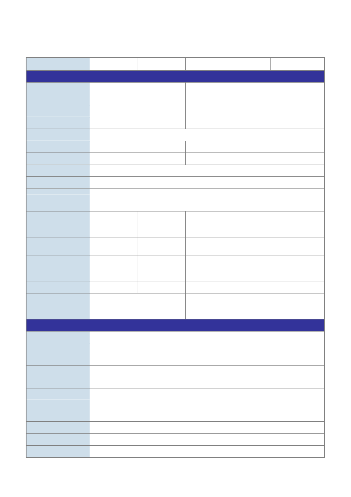
User’s Manual of SGSD-1022 / SGSD-1022P
SGSW-2840 / SGSW-2840P
1.5 Product Specification
Product SGSD-1022 SGSD-1022P SGSW-2840 SGSW-2840R SGSW-2840P
Hardware Specification
10/100Mbps Copper
Ports
1000Mbps Copper Ports
SFP/mini-GBIC Slots
Switch Architecture
Switch Fabric
Switch Throughput
Address Table
Share Data Buffer
Flow Control
LED
Power Consumption
Dimensions ( W x D x H)
8-Port 10/ 100Base-TX RJ-45
Auto-MDI/MDI-X
2 4
2, shared with Port-9 and Port-10 4, shared with Port-25~Port-28
Store-and-Forward
5.6Gbps / non-blocking 12.8Gbps / non-blocking
4.16Mpps @64Bytes 9.52Mpps @64Bytes
8K entries
2 Mbits
Back pressure for Half-Duplex
IEEE 802.3x Pause Frame for Full-Duplex
Power, Link/Act
and speed per port
Max. 10.5 watts /
32.6 BTU
330 x 155 x
43.5mm
1U height
Power, Link/Act,
PoE and speed
per port
Max. 130 watts /
443 BTU
330 x 155 x
43.5mm
1U height
24-Port 10/ 100Base-TX RJ-45
Auto-MDI/MDI-X
Power, Link/Act and speed per port
Max. 20 watts / 68.5 BTU
430 x 178 x 44.5mm, 1U height
Power, Link/Act, PoE
and speed per port
Max. 260 watts / 887
BTU
440 x 265 x 44mm,
1U height
Weight
Power
Layer 2 Function
Management Interface
Port Configuration
Port Status
Bandwidth Control
VLAN
Link Aggregation
QoS
1.3kg 2.0kg 2.8 KG 3.0kg 5.87 kg
AC 100~240V, 50/60Hz
Console, Telnet, SSH, Web Browser, SSL, SNMPv1, v2c and v3
Port disable/enable. Auto-negotiation 10/100/1000Mbps full and half duplex mode selection. Flow
Control disable / enable
Display each port’s speed duplex mode, link status and Flow control status. Auto negotiation
status, trunk status.
Input Rate Limit
Output Traffic Shaper
Allow to configure per 10K or 1M
IEEE 802.1Q Tagged Based VLAN ,up to 256 VLAN groups
Supports 12 groups of 8-Port trunk, IEEE 802.3ad LACP
Traffic classification based on Port Number, 802.1p priority, DS/TOS field in IP Packet
AC 100~240V,
50/60Hz
AC : 100~240V,
50/60Hz
DC: 30~60V
AC 100~240V,
50/60Hz
28
Page 29

IGMP Snooping
User’s Manual of SGSD-1022 / SGSD-1022P
SGSW-2840 / SGSW-2840P
IGMP (v1/v2) Snooping, up to 256 multicast Groups
Access Control List
SNMP MIBs
Power over Ethernet
PoE Standard
PoE Power Supply Type
PoE Power Output
Power Pin Assignment
IP-Based ACL / MAC-Based ACL, up to 256 entries
RFC-1213 MIB-II
RFC-2863 Interface MIB
RFC-2665 EtherLike MIB
RFC-1493 Bridge MIB
RFC-2674 Extended Bridge MIB
RFC-2819 RMON MIB (Group 1, 2, 3,9)
RFC-2737 Entity MIB
RFC-2618 RADIUS Client MIB
-- IEEE 802.3af
Power over
Ethernet / PSE
-- End-Span -- -- End-Span
-- Per Port 48V DC,
350mA . Max. 15.4
watts
-- 1/2(+), 3/6(-) -- -- 1/2(+), 3/6(-)
-- -- IEEE 802.3af Power
-- -- Per Port 48V DC,
over Ethernet / PSE
350mA . Max. 15.4
watts
PoE Power Budget
Standards Conformance
Regulation Compliance
Standards Compliance
FCC Part 15 Class A, CE
IEEE 802.3
IEEE 802.3u
IEEE 802.3z
IEEE 802.3ab
IEEE 802.3x
IEEE 802.3ad
IEEE 802.1d
IEEE 802.1w
IEEE 802.1s
IEEE 802.1p
IEEE 802.1Q
IEEE 802.1v
IEEE 802.1x
IEEE 802.3af
Environment Specifications
Operating
Temperature: 0 degree C ~ 50 degree C
Relative Humidity: 20% ~95% (non-condensing)
-- 110 Watts -- -- 230 Watts
10Base-T
100Base-TX
1000Base- SX/LX
1000Base-T
Flow Control and Back pressure
Port trunk with LACP
Spanning tree protocol
Rapid spanning tree protocol
Multiple Spanning tree protocol
Class of service
VLAN Tagging
Protocol VLAN
Port Authentication Network Control
Power over Ethernet, Powered Source Equipment
Storage
Temperature: -40 degree C ~ 70 degree C
Relative Humidity: 20% ~ 95% (non-condensing)
29
Page 30
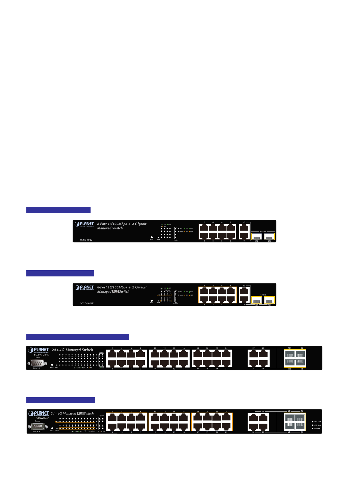
User’s Manual of SGSD-1022 / SGSD-1022P
SGSW-2840 / SGSW-2840P
2. INSTALLATION
This section describes the hardware features and installation of the Managed Switch on the desktop or rack mount. For easier
management and control of the switch, familiarize yourself with its display indicators, and ports. Front panel illustrations in this
chapter display the unit LED indicators. Before connecting any network device to the switch, please read this chapt er
completely.
2.1 Hardware Description
2.1.1 Switch Front Panel
The unit front panel provides a simple interface monitoring the switch. Figure 2-1 to 2-4 shows the front panel of the Managed
Switches.
SGSD-1022 Front Panel
SGSD-1022P Front Panel
SGSW-2840 / SGSW-2840R Front Panel
Figure 2-1 SGSD-1022 front panel.
Figure 2-2 SGSD-1022P front panel.
SGSW-2840P Front Panel
Figure 2-3 SGSW-2840 front panel.
Figure 2-4 SGSW-2840P front panel.
30
Page 31

User’s Manual of SGSD-1022 / SGSD-1022P
SGSW-2840 / SGSW-2840P
■ Gigabit TP interface
10/100/1000Base-T Copper, RJ-45 Twist-Pair: Up to 100 meters.
■ Gigabit SFP slots
1000Base-SX/LX mini-GBIC slot, SFP (Small Factor Pluggable) transceiver module: From 550 meters (Multi-mode fiber),
up to 10/30/50/70/120 kilometers (Single-mode fiber).
■ Console Port
The console port is a DB9, RS-232 male seria port connector. It is an interface for connecting a terminal directly. Through
the console port, it provides rich diagnostic information includes factory reset, forgotten password access, network statistics,
link status and system setting. Users can use the attached RS-232 cable in the package and connect to the console port on
the device. After the connection, users an run any terminal emulation program (Hyper Terminal, ProComm Plus, Telix,
Winterm and so on) to enter the statup screen of the device.
2.1.2 LED Indications
The front panel LEDs indicates instant status of port links, data activity, system operation, PoE in use status and system power,
helps monitor and troubleshoot when needed.
SGSD-1022 LED indication
Figure 2-5 SGSD-1022 LED panel
■ System
LED Color Function
PWR Green
Lights to indicate that the Switch is powered on.
Blink to indicate the System is running under booting procedure.
■ 10/100Base-TX interfaces (Port-1 to Por-8)
LED Color Function
LNK/ACT Green
100 Orange
Lights:
Blink:
Lights: indicate that the port is operating at 100Mbps.
Off: If LNK/ACT LED light-> indicate that the port is operating at 10Mbps
To indicate the link through that port is successfully established.
To indicate that the switch is actively sending or receiving data over that port.
If LNK/ACT LED Off -> indicate that the port is link down
31
Page 32

User’s Manual of SGSD-1022 / SGSD-1022P
■ 10/100/1000Base-T interfaces (Port-9 and Port-10) and SFP interfaces
LED Color Function
SGSW-2840 / SGSW-2840P
1000
Green
LNK/ACT
10/100
Orange
LNK/ACT
SGSD-1022P LED indication
Lights:
Blink:
Off:
Lights:
Blink:
Off:
To indicate the link through that port is successfully established with speed
1000Mbps
To indicate that the switch is actively sending or receiving data over that port.
If L10/100 NK/ACT LED light-> indicate that the port is operating at 10Mbps or
100Mbps
If LNK/ACT LED Off -> indicate that the port is link down
To indicate the link through that port is successfully established with speed
10Mbps or 100Mbps
To indicate that the switch is actively sending or receiving data over that port.
If 1000 LNK/ACT LED light-> indicate that the port is operating at 1000Mbps
If 1000 LNK/ACT LED Off -> indicate that the port is link down
Figure 2-6 SGSD-1022P LED panel
■ System
LED Color Function
PWR Green
■ 10/100Base-TX , PoE interfaces (Port-1 to Por-8)
LED Color Function
LNK/ACT Green
PoE In-Use Orange
Lights to indicate that the Switch is powered on.
Blink to indicate the System is running under booting procedure.
Lights:
Blink:
Lights:
Off:
To indicate the link through that port is successfully established.
To indicate that the switch is actively sending or receiving data over that port.
To indicate the port is providing 48VDC in-line power
To indicate the connected device is not a PoE Powered Device (PD)
32
Page 33

User’s Manual of SGSD-1022 / SGSD-1022P
■ 10/100/1000Base-T interfaces (Port-9 and Port-10) and SFP interfaces
LED Color Function
SGSW-2840 / SGSW-2840P
Lights:
1000
Green
LNK/ACT
10/100
Orange
LNK/ACT
SGSW-2840 / SGSW-2840R LED indication
Blink:
Off:
Lights:
Blink:
Off:
To indicate the link through that port is successfully established with speed
1000Mbps
To indicate that the switch is actively sending or receiving data over that port.
If L10/100 NK/ACT LED light-> indicate that the port is operating at 10Mbps or
100Mbps
If LNK/ACT LED Off -> indicate that the port is link down
To indicate the link through that port is successfully established with speed
10Mbps or 100Mbps
To indicate that the switch is actively sending or receiving data over that port.
If 1000 LNK/ACT LED light-> indicate that the port is operating at 1000Mbps
If 1000 LNK/ACT LED Off -> indicate that the port is link down
Figure 2-7 SGSW-2840 LED panel
■ System
LED Color Function
PWR Green
■ 10/100Base-TX interfaces (Port-1 to Por-24)
LED Color Function
LNK/ACT Green
100 Orange
■ 10/100/1000Base-T interfaces (Port-25 to Port-28) and SFP interfaces
Lights to indicate that the Switch is powered on.
Blink to indicate the System is running under booting procedure.
Lights:
Blink:
Lights: indicate that the port is operating at 100Mbps.
Off: If LNK/ACT LED light-> indicate that the port is operating at 10Mbps
To indicate the link through that port is successfully established.
To indicate that the switch is actively sending or receiving data over that port.
If LNK/ACT LED Off -> indicate that the port is link down
33
Page 34
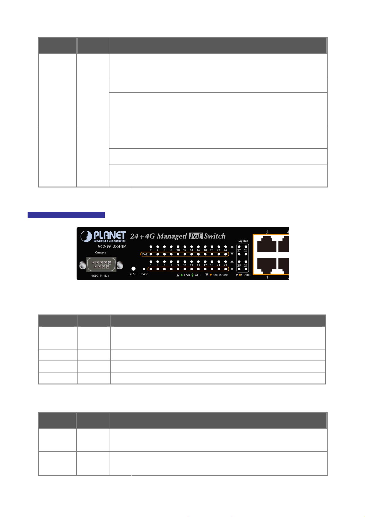
User’s Manual of SGSD-1022 / SGSD-1022P
SGSW-2840 / SGSW-2840P
LED Color Function
1000
Green
LNK/ACT
10/100
Orange
LNK/ACT
SGSW-2840P LED indication
Lights:
Blink:
Off:
Lights:
Blink:
Off:
To indicate the link through that port is successfully established with speed
1000Mbps
To indicate that the switch is actively sending or receiving data over that port.
If L10/100 NK/ACT LED light-> indicate that the port is operating at 10Mbps or
100Mbps
If LNK/ACT LED Off -> indicate that the port is link down
To indicate the link through that port is successfully established with speed
10Mbps or 100Mbps
To indicate that the switch is actively sending or receiving data over that port.
If 1000 LNK/ACT LED light-> indicate that the port is operating at 1000Mbps
If 1000 LNK/ACT LED Off -> indicate that the port is link down
Figure 2-8 SGSW-2840P LED panel
■ System
LED Color Function
PWR Green
PWR Alert Green Lights to indicate that the power supply failure
FAN1 Alert Green Lights to indicate that the FAN1 failure
FAN2 Alert Green Lights to indicate that the FAN2 failure
■ 10/100Base-TX, PoE interfaces (Port-1 to Por-24)
LED Color Function
LNK/ACT Green
Lights to indicate that the Switch is powered on.
Blink to indicate the System is running under booting procedure.
Lights:
Blink:
To indicate the link through that port is successfully established.
To indicate that the switch is actively sending or receiving data over that port.
PoE In-Use Orange
Lights:
Off:
To indicate the port is providing 48VDC in-line power
To indicate the connected device is not a PoE Powered Device (PD)
34
Page 35

User’s Manual of SGSD-1022 / SGSD-1022P
■ 10/100/1000Base-T interfaces (Port-25 to Port-28) and SFP interfaces
LED Color Function
SGSW-2840 / SGSW-2840P
Lights:
To indicate the link through that port is successfully established with speed
1000Mbps
1000
Blink:
To indicate that the switch is actively sending or receiving data over that port.
Green
LNK/ACT
Off:
If L10/100 NK/ACT LED light-> indicate that the port is operating at 10Mbps or
100Mbps
If LNK/ACT LED Off -> indicate that the port is link down
Lights:
To indicate the link through that port is successfully established with speed
10Mbps or 100Mbps
10/100
Orange
Blink:
To indicate that the switch is actively sending or receiving data over that port.
LNK/ACT
Off:
If 1000 LNK/ACT LED light-> indicate that the port is operating at 1000Mbps
If 1000 LNK/ACT LED Off -> indicate that the port is link down
2.1.3 Switch Rear Panel
The rear panel of the Managed Switch indicates an AC inlet power socket, which accept input power from 100 to 240V AC,
50-60Hz. Figure 2-9 to Figure 2-13 shows the rear panel of these Managed Switches
SGSD-1022 Rear Panel
Figure 2-9 Rear panel of SGSD-1022
SGSD-1022P Rear Panel
Figure 2-10 Rear panel of SGSD-1022P
Power
Power
35
Page 36

SGSW-2840 Rear Panel
SGSW-2840R Rear Panel
User’s Manual of SGSD-1022 / SGSD-1022P
SGSW-2840 / SGSW-2840P
Figure 2-11 Rear panel of SGSW-2840
Figure 2-12 Rear panel of SGSW-2840R
Figure 2-13 Rear panel of SGSW-2840
SGSW-2840P Rear Panel
Figure 2-14 Rear panel of SGSW-2840P
■ Power Receptacle
For compatibility with electric service in most areas of the world, the WGS3-Layer 3 Switch’s power supply automatically
adjusts to line power in the range 100-240VAC and 50/60 Hz.
Plug the female end of the power cord firmly into the receptalbe on the rear panel of the Switch. Plug the other end of the
36
Page 37

power cord into an electric service outlet then the power will be ready.
The device is a power-required device, it means, it will not work till it is powered. If your networks should
active all the time, please consider using UPS (Uninterrupted Power Supply) for your device. It will
User’s Manual of SGSD-1022 / SGSD-1022P
SGSW-2840 / SGSW-2840P
Power Notice:
prevent you from network data loss or network downtime.
In some area, installing a surge suppression device may also help to protect your Managed Switch from
being damaged by unregulated surge or current to the Switch or the power adapter.
37
Page 38

User’s Manual of SGSD-1022 / SGSD-1022P
SGSW-2840 / SGSW-2840P
2.2 Install the Switch
This section describes how to install your Managed Switch and make connections to the Managed Switch. Please read the
following topics and perform the procedures in the order being presented. To install your Managed Switch on a desktop or shelf,
simply complete the following steps.
2.2.1 Desktop Installation
To install the Managed Switch on desktop or shelf, please follows these steps:
Step1: Attach the rubber feet to the recessed areas on the bottom of the Managed Switch.
Step2: Place the Managed Switch on the desktop or the shelf near an AC power source, as shown in Figure 2-4.
Figure 2-15 Place the Switch on the desktop
Step3: Keep enough ventilation space between the Managed Switch and the surrounding objects.
When choosing a location, please keep in mind the environmental restrictions discussed in Chapter
1, Section 4, and Specification.
Step4: Connect the Managed Switch to network devices.
Connect one end of a standard network cable to the 10/100/1000 RJ-45 ports on the front of the Managed S witch
Connect the other end of the cable to the network devices such as printer servers, workstations or routers…etc.
Connection to the Managed Switch requires UTP Category 5 network cabling with RJ-45 tips. For
more information, please see the Cabling Specification in Appendix A.
Step5: Supply power to the Managed Switch.
Connect one end of the power cable to the Managed Switch.
Connect the power plug of the power cable to a standard wall outlet.
When the Managed Switch receives power, the Power LED should remain solid Green.
38
Page 39

User’s Manual of SGSD-1022 / SGSD-1022P
SGSW-2840 / SGSW-2840P
2.2.2 Rack Mounting
To install the Managed Switch in a 19-inch standard rack, please follows the instructions described below.
Step1: Place the Managed Switch on a hard flat surface, with the front panel positioned towards the front side.
Step2: Attach the rack-mount bracket to each side of the Managed Switch with supplied screws attached to the package.
Figure 2-16 and 2-17 shows how to attach brackets to one side of the Managed Switch.
Figure 2-16 Attach brackets to the Managed Switch.
Figure 2-17 Attach brackets to the Managed Switch.
You must use the screws supplied with the mounting brackets. Damage caused to the parts by
using incorrect screws would invalidate the warranty.
Step3: Secure the brackets tightly.
Step4: Follow the same steps to attach the second bracket to the opposite side.
Step5: After the brackets are attached to the Managed Switch, use suitable screws to securely attach the brackets to the rack,
as shown in Figure 2-17 and 2-18.
39
Page 40

User’s Manual of SGSD-1022 / SGSD-1022P
SGSW-2840 / SGSW-2840P
Figure 2-18 Mounting SGSD-1022 in a Rack
Figure 2-19 Mounting SGSW-2840 in a Rack
Step6: Proceeds with the steps 4 and steps 5 of session 2.2.1 Desktop Installation to connect the network cabling and supply
power to the Managed Switch.
40
Page 41

User’s Manual of SGSD-1022 / SGSD-1022P
SGSW-2840 / SGSW-2840P
2.2.3 Installing the SFP transceiver
The sections describe how to insert an SFP transceiver into an SFP slot.
The SFP transceivers are hot-pluggable and hot-swappable. You can plug-in and out the transceiver to/from any SFP port
without having to power down the Managed Switch. As the Figure 2-19 appears.
Figure 2-20 Plug-in the SFP transceiver
Approved PLANET SFP Transceivers
PLANET Managed Switch supports both Single mode and Multi-mode SFP transceiver. The following list of approved PLANET
SFP transceivers is correct at the time of publication:
■MGB-SX SFP (1000BASE-SX SFP transceiver )
■MGB-LX SFP (1000BASE-LX SFP transceiver )
It recommends using PLANET SFPs on the Managed Switch. If you insert a SFP transceiver that is
not supported, the Managed Switch will not recognize it.
Before connect the other Managed Switches, workstation or Media Converter.
1. Make sure both side of the SFP transceiver are with the same media type, for example: 1000Base-SX to 1000Base-SX,
1000Bas-LX to 1000Base-LX.
2. Check the fiber-optic cable type match the SFP transceiver model.
¾ To connect to 1000Base-SX SFP transceiver, use the Multi-mode fiber cable- with one side must be male duplex LC
connector type.
¾ To connect to 1000Base-LX SFP transceiver, use the Single-mode fiber cable-with one side must be male duplex LC
connector type.
41
Page 42
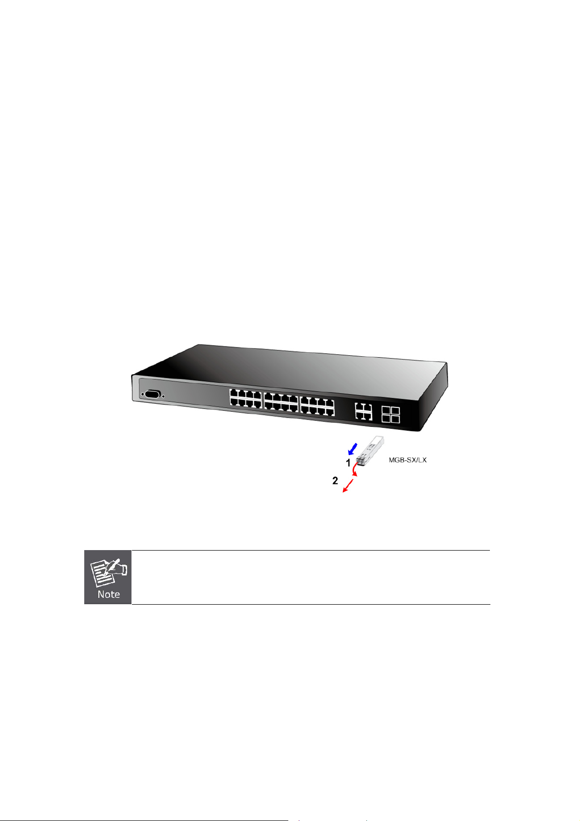
User’s Manual of SGSD-1022 / SGSD-1022P
SGSW-2840 / SGSW-2840P
Connect the fiber cable
1. Attach the duplex LC connector on the network cable into the SFP transceiver.
2. Connect the other end of the cable to a device – switches with SFP installed, fiber NIC on a workstation or a Media
Converter..
3. Check the LNK/ACT LED of the SFP slot on the front of the Managed Switch. Ensure that the SFP transceiver is operating
correctly.
4. Check the Link mode of the SFP port if the link failed. Co works with some fiber-NICs or Media Converters, set the Link
mode to “1000 Force” is needed.
Remove the transceiver module
1. Make sure there is no net work activity by consult or check with the network administrator. Or through the management
interface of the switch/converter (if available) to disable the port in advance.
2. Remove the Fiber Optic Cable gentl y.
3. Turn the handle of the MGB module to horizontal.
4. Pull out the module gently through the handle.
Figure 2-21 Pull out the SFP transceiver
Never pull out the module without pull the handle or the push bolts on the module. Direct pull
out the module with violent could damage the module and SFP module slot of the Managed
Switch.
42
Page 43

User’s Manual of SGSD-1022 / SGSD-1022P
SGSW-2840 / SGSW-2840P
3. SWITCH MANAGEMENT
This chapter explains the methods that you can use to configure management access to the Managed Switch. It describes the
types of management applications and the communication and management protocols that deliver data between your
management device (work-station or personal computer) and the system. It also contains information about port connection
options.
This chapter covers the following topics:
Requirements
Management Access Overview
Administration Console Access
Web Management Access
SNMP Access
Standards, Protocols, and Related Reading
3.1 Requirements
Workstations of subscribers running Windows 98/ME, NT4.0, 2000/XP, MAC OS9 or later, Linux, UNIX or other
platform compatible with TCP/IP protocols.
Workstation installed with Ethernet NIC (Network Interface Card)
Serial Port connect (Terminal)
• Above PC with COM Port (DB-9 / RS-232) or USB-to-RS-232 converter
Ethernet Port connect
• Network cables - Use standard network (UTP) cables with RJ45 connectors.
Above Workstation installed with WEB Browser and JAVA runtime environment Plug-in
It is recommended to use Internet Explore 6.0 or above to access Managed Switch.
43
Page 44

User’s Manual of SGSD-1022 / SGSD-1022P
SGSW-2840 / SGSW-2840P
3.2 Management Access Overview
The Managed Switch gives you the flexibility to access and manage it using any or all of the following methods:
An administration console
Web browser interface
An external SNMP-based network management application
The administration console and Web browser interface support are embedded in the Managed Switch software and are
available for immediate use. Each of these management methods has their own advantages. Table 3-1 compares the three
management methods.
Method Advantages Disadvantages
Console
Web Browser
SNMP Agent
• No IP address or subnet needed
• Text-based
• Telnet functionality and HyperTerminal
built into Windows
95/98/NT/2000/ME/XP operating
systems
• Secure
• Ideal for configuring the switch remotely
• Compatible with all popular browsers
• Can be accessed from any location
• Most visually appealing
• Communicates with switch functions at
the MIB level
• Based on open standards
• Must be near switch or use dial-up connection
• Not convenient for remote users
• Modem connection may prove to be unreliable
or slow
• Security can be compromised (hackers need
only know the IP address and subnet mask)
• May encounter lag times on poor connections
• Requires SNMP manager software
• Least visually appealing of all three methods
• Some settings require calculations
• Security can be compromised (hackers need
only know the community name)
Table 3-1 Management Methods Comparison
3.3 Administration Console
The administration console is an internal, character-oriented, and command line us er interface for performing system
administration such as displaying statistics or changing option settings. Using this method, you can vie w the administrati on
console from a terminal, personal computer, Apple Macintosh, or workstation connected to the switch's console (serial) port.
There are two ways to use this management method: via direct access or modem port access. The following sections describe
these methods. For more information about using the console, refer to Chapter 5 Command Line Interface Console
Management.
44
Page 45
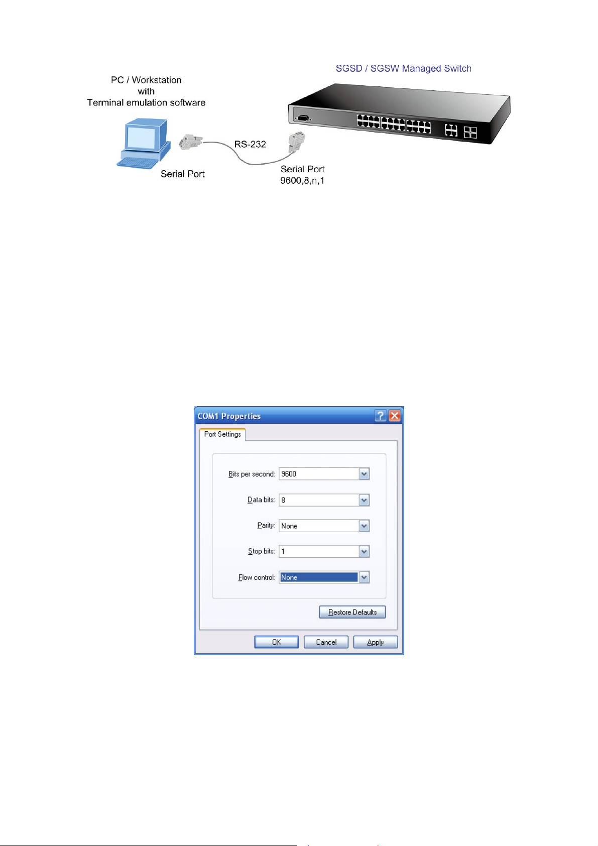
User’s Manual of SGSD-1022 / SGSD-1022P
SGSW-2840 / SGSW-2840P
Figure 3-1 Console management
Direct Access
Direct access to the administration console is achieved by directly connecting a terminal or a PC equipped with a
terminal-emulation program (such as HyperTerminal) to the Managed Switch console (serial) port.
When using this management method, a straight DB9 RS-232 cable is required to connect the switch to the PC. After making
this connection, configure the terminal-emulation program to use the following parameters:
The default parameters are:
9600 bps
8 data bits
No parity
1 stop bit
Figure 3-2 Terminal parameter settings
You can change these settings, if desired, after you log on. This management method is often preferred because you can
remain connected and monitor the system during system reboots. Also, certain error messages are sent to the serial port,
regardless of the interface through which the associated action was initiated. A Macintosh or PC attachment can use any
terminal-emulation program for connecting to the terminal serial port. A workstation attachment under UNIX can use an emulator
such as TIP.
45
Page 46
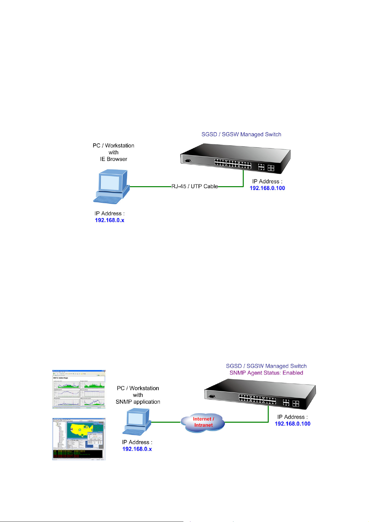
User’s Manual of SGSD-1022 / SGSD-1022P
SGSW-2840 / SGSW-2840P
3.4 Web Management
The Managed Switch provides a browser interface that lets you configure and manage the switch remotely. Af ter you set up your
IP address for the switch, you can access the Managed Switch's Web interface applications directly in your Web browser by
entering the IP address of the Managed Switch. You can then use your Web browser to list and manage the Managed Switch
configuration parameters from one central location, just as if you were directly connected to the Managed Switch's console port.
Web Management requires either Microsoft Internet Explorer 6.0 or later, Safari or Mozilla Firefox 1.5 or later.
Figure 3-3 Web management
3.5 SNMP-Based Network Management
You can use an external SNMP-based application to configure and manage the Managed Switch, such as SNMPc Network
Manager, HP Openview Network Node Management (NNM) or What’s Up Gold. This management method requires the SNMP
agent on the switch and the SNMP Network Management Station to use the same community string. This management
method, in fact, uses two community strings: the get community string and the set community string. If the SNMP Net-work
management Station only knows the set community string, it can read and write to the MIBs. However, if it only knows the get
community string, it can only read MIBs. The default gets and sets community strings for the Managed Switch are public.
Figure 3-4 SNMP management
46
Page 47

User’s Manual of SGSD-1022 / SGSD-1022P
SGSW-2840 / SGSW-2840P
3.6 Protocols
The Managed Switch supports the following protocols:
Virtual terminal protocols, such as Telnet
Simple Network Management Protocol (SNMP)
3.6.1 Virtual Terminal Protocols
A virtual terminal protocol is a software program, such as Telnet, that allows you to establish a management session from a
Macintosh, a PC, or a UNIX workstation. Because T elnet runs over TCP/IP, you must have at least one IP address configured on
the Managed Switch before you can establish access to it with a virtual terminal protocol.
Terminal emulation differs from a virtual terminal protocol in that you must connect a terminal directly
to the console (serial) port.
3.6.2 SNMP Protocol
Simple Network Management Protocol (SNMP) is the standard management protocol for multi-vendor IP networks. SNMP
supports transaction-based queries that allow the protocol to format messages and to transmit information between reporting
devices and data-collection programs. SNMP runs on top of the User Datagram Protocol (UDP), offering a connectionless-mode
service.
3.6.3 Management Architecture
All of the management application modules use the same Messaging Application Programming Interface (MAPI). By unifying
management methods with a single MAPI, configuration parameters set using one method (console port, for example) are
immediately displayable by the other management methods (for exam ple, SNMP agent of Web browser).
The management architecture of the switch adheres to the IEEE open standard. This compliance assures customers that the
Managed Switch is compatible with, and will interoperate with other solutions that adhere to the same open standard.
47
Page 48
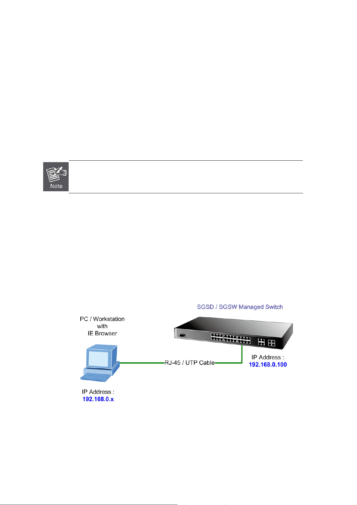
User’s Manual of SGSD-1022 / SGSD-1022P
SGSW-2840 / SGSW-2840P
4. WEB CONFIGURATION
This section introduces the configuration and functions of the Web-Based management.
About Web-based Management
The Managed Switch offers management features that allow users to manage the Managed Switch from anywhere on the
network through a standard browser such as Microsoft Internet Explorer.
The Web-Based Management supports Internet Explorer 6.0. It is based on Java Applets with an aim to reduce network
bandwidth consumption, enhance access speed and present an easy viewing screen.
By default, IE6.0 or later version does not allow Java Applets to open sockets. The user has to
explicitly modify the browser setting to enable Java Applets to use network ports.
The Managed Switch can be configured through an Ethernet connection, make sure the manager PC must be set on s ame the
IP subnet address with the Managed Switch.
For example, the default IP address of the SGSD / SGSW Managed Switch is 192.168.0.100, then the manager PC should be
set at 192.168.0.x (where x is a number between 1 and 254, except 100), and the default subnet mask is 255.255.255.0.
If you have changed the default IP address of the Managed Switch to 192.168.1.1 with subnet mask 255.255.255.0 via console,
then the manager PC should be set at 192.168.1.x (where x is a number between 2 and 254) to do the relative configuration on
manager PC.
Figure 4-1-1 Web Management
48
Page 49
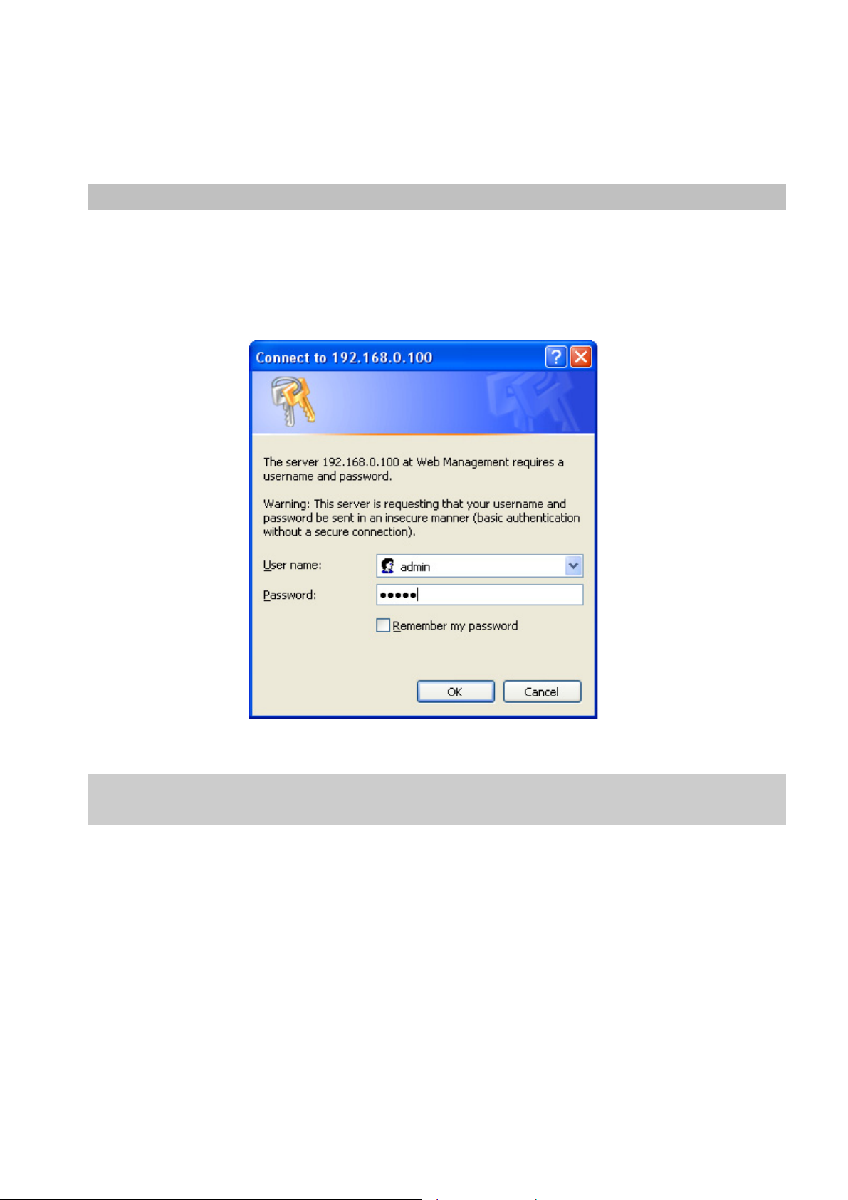
User’s Manual of SGSD-1022 / SGSD-1022P
SGSW-2840 / SGSW-2840P
Logging on the switch
1. Use Internet Explorer 6.0 or above Web browser. Enter the factory-default IP address to access the Web interface. The
factory-default IP Address as following:
http://192.168.0.100
2. When the following login screen appears, please enter the default username "admin" with password “admin” (or the
username/password you have changed via console) to login the main screen of Managed Switch. The login screen in
Figure 4-1-2 appears.
Figure 4-1-2 Login screen
Default User name: admin
Default Password: admin
After entering the username and password, the main screen appears as Figure 4-1-3.
49
Page 50

User’s Manual of SGSD-1022 / SGSD-1022P
SGSW-2840 / SGSW-2840P
Figure 4-1-3 Default main page
Now, you can use the Web management interface to continue the switch management or manage the Managed Switch by Web
interface. The Switch Menu on the left of the web page let you access all the commands and statistics the Managed Switch
provides.
1. It is recommended to use Internet Explore 6.0 or above to access Managed Switch.
2. The changed IP address take effect immediately after click on the Apply button, you need to
use the new IP address to access the Web interface.
3. The changed IP address remains the origi nal after reboot the switch unless the
configuration is saved. To save the changed IP address, please move to System \ File
Management \ Copy menu and select “running-config to startup-config”.
50
Page 51
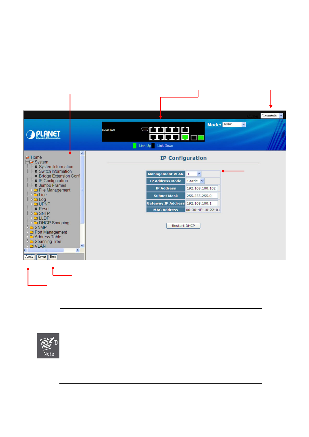
User’s Manual of SGSD-1022 / SGSD-1022P
SGSW-2840 / SGSW-2840P
4.1 Main WEB PAGE
The SGSD / SGSW Managed Switch provides a Web-based browser interface for configuring and managing it. This interface
allows you to access the Managed Switch using the Web browser of your choice. This chapter describes how to use the
Managed Switch’s Web browser interface to configure and manage it.
Main Functions Menu
Port Link Status
IP Stacking
Member switch
Main Screen
Apply Button
Help Button
1. To ensure proper screen refresh, be sure that Internet Explorer is configured so that the
setting “Check for newer versions of stored pages” reads “Every visit to the page”.
• Internet Explorer 6.x and earlier: This option is available under the menu “Tools / Internet
Options / General / Temporary Internet Files / Settings”.
• Internet Explorer 7.x: This option is available under “Tools / Internet Options / General /
2. You may have to manually refresh the screen after making configuration changes by
Browsing History / Settings / Temporary Internet Files”.
pressing the browser’s
Figure 4-1-4 Main Page
51
Page 52
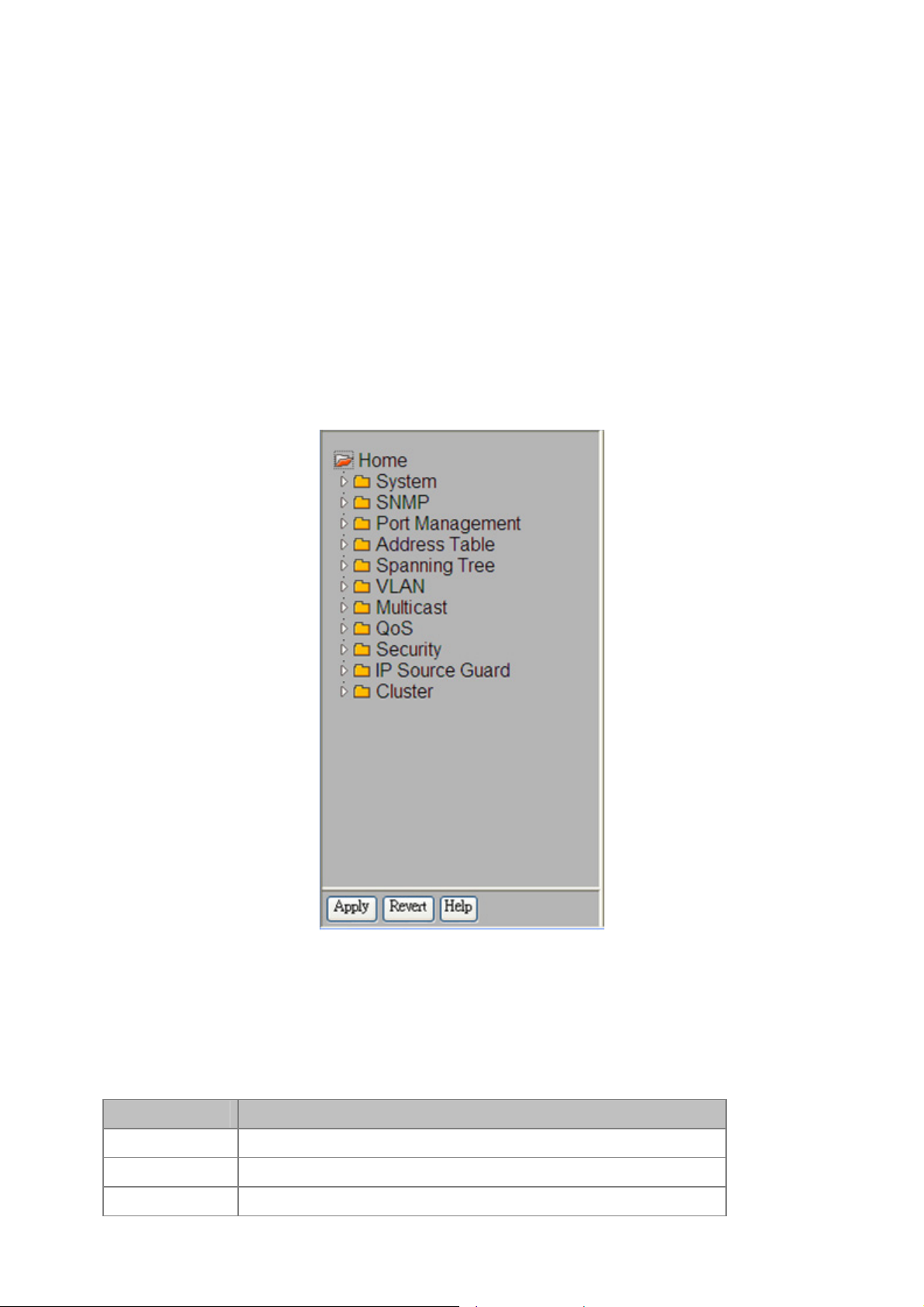
User’s Manual of SGSD-1022 / SGSD-1022P
SGSW-2840 / SGSW-2840P
Panel Display
The web agent displays an image of the Managed Switch’s ports. The Mode can be set to display different information for the
ports, including Active (i.e., up or down), Duplex (i.e., half or full duplex, or Flow Control (i.e., with or without flow control).
Clicking on the image of a port opens the Port Configuration page.
Main Menu
Using the onboard web agent, you can define system parameters, manage and control the Managed Switch, and all its ports, or
monitor network conditions. The following table briefly describes the selections available from this progra m .
Via the Web-Management, the administrator can setup the Managed Switch by select the functions those listed in the Main
Function. The screen in Figure 4-1-5 appears.
Figure 4-1-5 SGSD/SGSW Managed Switch Main Funcrions Menu
Configuration Options
Configurable parameters have a dialog box or a drop-down list. Once a configuration change has been made on a page, be
sure to click on the Apply button to confirm the new setting. The following table summarizes the web page configuration buttons.
Button Action
Apply
Revert
Help
Sets specified values to the system.
Cancels specified values and restores current values prior to pressing Apply.
Links directly to webhelp.
52
Page 53

The following Main functions can be configured here:
System
SNMP
Port Management
Address Table
Spanning Tree
VLAN
Multicast
QoS
User’s Manual of SGSD-1022 / SGSD-1022P
SGSW-2840 / SGSW-2840P
Security
Cluster
53
Page 54

User’s Manual of SGSD-1022 / SGSD-1022P
SGSW-2840 / SGSW-2840P
4.2 System
Use the System menu items to display and configure basic administrative details of the Manage d Switch. Under System the
following topics are provided to configure and view the system information: This section has the following items:
■ System
Information
■ Switch
Information
■ Bridge Extension
Configuration
■ IP Configuration
■ Jumbo Frames
■ File Management
■ Line
■ Log
Provides basic system description, including contact information
Shows the number of ports, and hardware/firmware version numbers
Shows the bridge extension parameters
Sets the IP address for management access
Enables jumbo frame packets.
Copy Operation
Delete
Set Start-Up
Sets console port and telnet connection parameters
Logs
System Logs
Remote Logs
SMTP
Allows the transfer and copying files
Allows deletion of files from the flash memory
Sets the startup file
Stores and displays error messages
Sends error messages to a logging process
Configures the logging of messages to a remote logging
process
Sends an SMTP client message to a participating server.
■ Reset
■ SNTP
■ LLDP
Restarts the switch
Simple Network Time Protocol. Configures SNTP client settings, including broadcast
mode or aspecified list of servers
Link Layer Discovery Protocol
54
Page 55

User’s Manual of SGSD-1022 / SGSD-1022P
SGSW-2840 / SGSW-2840P
4.2.1 System Information
Use the System Information screen to display descriptive information about the Managed Switch, or for quick system
identification. You can easily identify the system by displaying the device name, location and contact information. The System
Information screen in Figure 4-2-1 appears.
The page includes the following fields:
Object Description
• System Name -
• Object ID -
• Location -
• Contact -
• System Up time -
Figure 4-2-1 System Information screenshot
Enter the name you want to use to identify this switch.
You may use up to 31 alpha-numeric characters.
The factory default is blank.
The base object ID for the Managed Switch's enterprise MIB.
Enter the location of this Managed Switch.
You may use up to 31 alpha-numeric characters. The factory default is blank.
Enter the contact person for this switch.
You may use up to 31 alpha-numeric characters.
The factory default is blank.
The time in days, hours and minutes since the last switch reboot.
This page also includes a Telnet button that allows access to the Command Line Interface via Telnet.
55
Page 56
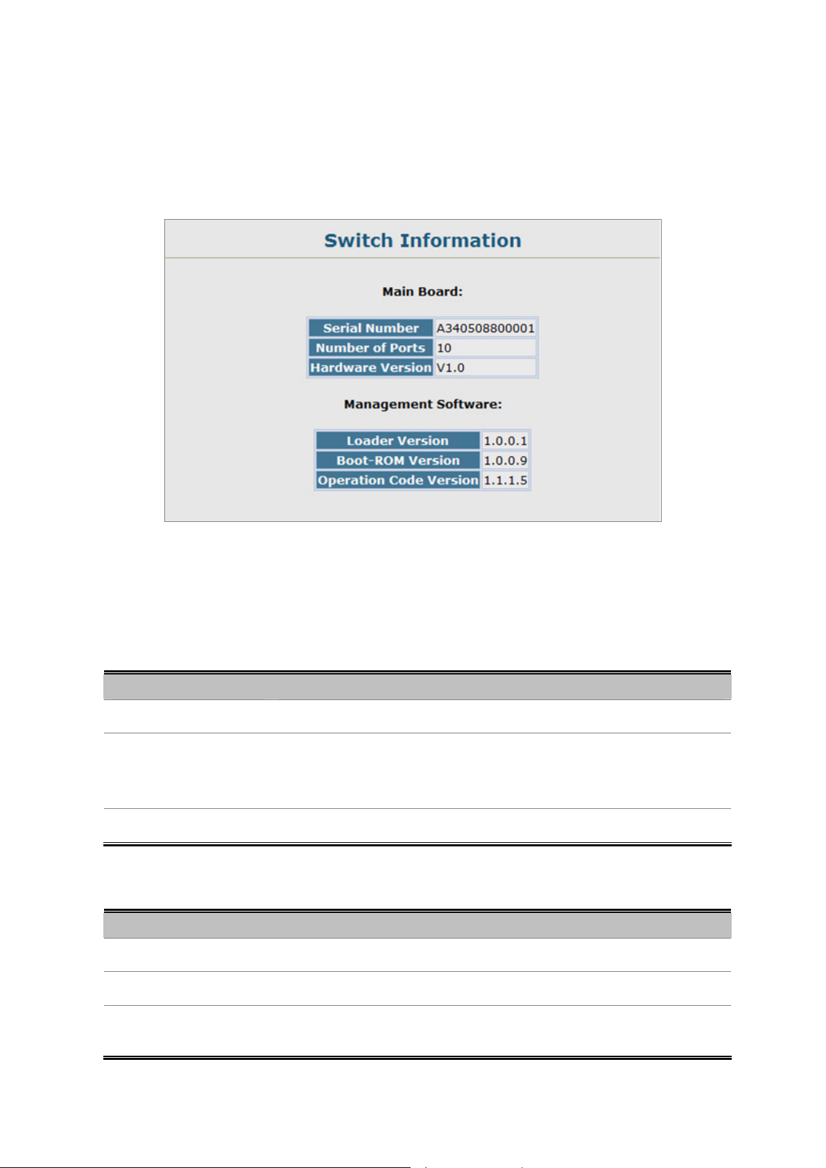
User’s Manual of SGSD-1022 / SGSD-1022P
SGSW-2840 / SGSW-2840P
4.2.2 Switch Information
Use the Switch Information page to display hardware/firmware version numbers for the main board and management software,
as well as the number of ports of the system. The Switch Information screen in Figure 4-2-2 appears.
The page includes the following fields:
■ Main Board
Object Description
• Serial Number
• Number of Ports
• Hardware Version
■ Management Software
Figure 4-2-2 Switch Information screenshot
The serial number of the Managed Switch.
Number of built-in RJ-45 ports. The default value of each model as below:
SGSD-1022 / SGSD-1022P: 10
SGSW-2840 / SGSW-2840P : 28
Hardware version of the main board.
Object Description
• Loader Version
• Boot-ROM Version
• Operation Code
Version
Version number of loader code.
Version of Power-On Self-Test (POST) and boot code.
Version number of runtime code.
56
Page 57

User’s Manual of SGSD-1022 / SGSD-1022P
SGSW-2840 / SGSW-2840P
4.2.3 Bridge Extension Configuration
The Bridge MIB includes extensions for managed devices that support Multicast Filtering, Traffic Classes, and Virtual LANs.
You can access these extensions to display default settings for the key variables, or to configure the glo bal setting for GARP
VLAN Registration Protocol (GVRP).
The Bridge Extension Configuration screen in Figure 4-2-3 appears.
Figure 4-2-3 Bridge Extension Configuration screenshot
The page includes the following fields:
Object Description
• Extended Multicast
Filtering Services
• Traffic Classes
• VLAN Learning
• Configurable PVID
Tagging
• Local VLAN Capable
This Managed Switch does not support the filtering of individual multicast
addresses based on GMRP (GARP Multicast Registration Protocol).
This Managed Switch provides mapping of user priorities to multiple traffic
classes. (Refer to “Class of Service Configuration”)
This Managed Switch uses Independent VLAN Learning (IVL), where each port
maintains its own filtering database.
This Managed Switch allows you to override the default Port VLAN ID (PVID
used in frame tags) and egress status (VLAN-Tagged or Untagged) on each port.
(Refer to “VLAN Configuration”.)
This Managed Switch does not support multiple local bridges outside of the
scope of 802.1Q defined VLANs.
• GMRP
GARP Multicast Registration Protocol (GMRP) allows network devices to
register endstations with multicast groups. This Managed Switch does not
support GMRP; it uses the Internet Group Management Protocol (IGMP) to
provide automatic multicast filtering.
57
Page 58

User’s Manual of SGSD-1022 / SGSD-1022P
SGSW-2840 / SGSW-2840P
4.2.4 IP Configuration
This section describes how to configure an IP interface for management access over the network. The IP address for the stack
is obtained via DHCP by default. To manually configure an address, you need to ch ange the Managed Switch’s default settings
to values that are compatible with your network. You may also need to an establish a default gateway between the stack and
management stations that exist on another network segment.
You can manually configure a specific IP address, or direct the device to obtain an address from a BOOTP or DHCP server.
Valid IP addresses consist of four decimal numbers, 0 to 255, separated by periods.
Figure 4-2-4 IP Configuration screenshot
Object Description
• Management VLAN
• IP Address Mode
ID of the configured VLAN (1-4094). This is the only VLAN through which you
can manage the Managed Switch.
By default, all ports on the Managed Switch are members of VLAN 1. However,
the management station can be attached to a port belonging to any VLAN, as
long as that VLAN has been assigned an IP address.
Specifies whether IP functionality is enabled via :
Static - manual configuration
DHCP - Dynamic Host Configuration Protocol
BOOTP - Boot Protocol
If DHCP/BOOTP is enabled, IP will not function until a reply has been received
from the server. Requests will be broadcast periodically by the switch for an IP
address. (DHCP/BOOTP values can include the IP address, subnet mask, and
default gateway.)
• IP Address
Address of the VLAN interface that is allowed management access. Valid IP
addresses consist of four numbers, 0 to 255, separated by periods.
(Default: 192.168.0.100)
58
Page 59

User’s Manual of SGSD-1022 / SGSD-1022P
SGSW-2840 / SGSW-2840P
• Subnet Mask
This mask identifies the host address bits used for routing to specific subnets.
(Default: 255.255.255.0)
• Gateway IP address
• MAC Address
• Restart DHCP
If you lose your management connection, use a console connection and enter “show ip
interface” to determine the new switch address.
Manual Configuration
1. Click System, IP Configuration.
2. Select the VLAN through which the management station is attached, set the IP Address Mode to “Static,” enter the IP
address, subnet mask and gateway, then click A pply.
IP address of the gateway router between this device and management stations
that exist on other network segments.
(Default: 0.0.0.0)
The physical layer address for this Managed Switch.
Requests a new IP address from the DHCP server.
Using DHCP/BOOTP
If your network provides DHCP/BOOTP services, you can configure the Managed Switch to be dynamically configured by these
services.
1. Click System, IP Configuration.
2. Specify the VLAN to which the management station is attached, set the IP Address Mode to DHCP or BOOTP.
3. Click Apply to save your changes.
4. Then click Restart DHCP to immediately request a new address.
The Managed Switch will also broadcast a request for IP configuration settings on each
power reset.
Renewing DCHP
DHCP may lease addresses to clients indefinitely or for a specific period of time. If the address expires or the switch is moved to
another network segment, you will lose management access to the switch. In this case, you can reboot the switch or submit a
client request to restart DHCP service via the CLI.
1. If the address assigned by DHCP is no longer functioning, you will not be able to renew the IP settings via the web
interface.
2. You can only restart DHCP service via the Web interface if the current address is still available.
59
Page 60

User’s Manual of SGSD-1022 / SGSD-1022P
SGSW-2840 / SGSW-2840P
4.2.5 Jumbo Frames
The Managed Switch provides more efficient throughput for large sequential data transfers by supporting jumbo frames up to
9216 bytes. Compared to standard Ethernet frames that run only up to 1.5 KB, using jumbo frames significantly reduces the
per-packet overhead required to process protocol encapsulation fields.
The Jumbo Frames configure screen in Figure 4-2-5 appears.
Figure 4-2-5 Jumbo Frames configure screenshot
Object Description
• Jumbo Packet Status
Configures support for jumbo frames.
(Default: Disabled)
4.2.6 File Management
The system file folder contains firmware and configuration settings. This section has the following options:
Copy Operation
Delete
Allows the transfer and copying files, such as:
- Downloading System Software from a Server
- Downloading Configuration Settings from a Server
- Saving Configuration Settings
- Restoring Configuration Settings
Allows deletion of files from the flash memory
Set Start-Up
Sets the startup file
4.2.6.1 Copy Operation
You can upload/download firmware or configuration to or from a TFTP server. By saving runtime code to a file on a TFTP
server, that file can later be downloaded to the Managed Switch to restore operation.
You can also set the Managed Switch to use new firmware without overwriting the previous version. You must specify the
method of file transfer, along with the file type and file names as required.
60
Page 61
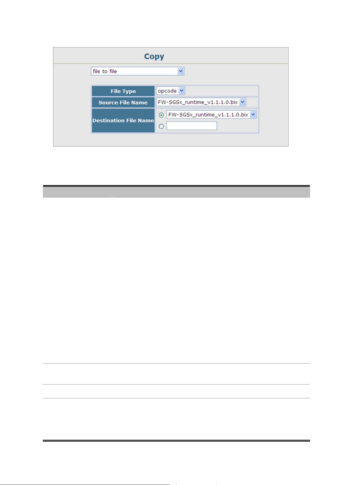
The page includes the following fields:
User’s Manual of SGSD-1022 / SGSD-1022P
SGSW-2840 / SGSW-2840P
Figure 4-2-6 default Copy Operation screenshot
Object Description
• File Transfer Method
The configuration copy operation includes these options:
-file to file – Copies a file within the switch directory, assigning it a new name.
-file to running-config – Copies a file in the switch to the running configuration.
-file to startup-config – Copies a file in the switch to the startup configuration.
-file to tftp – Copies a file from the switch to a TFTP server.
-running-config to file – Copies the running configuration to a file.
-running-config to startup-config – Copies the running config to the startup
config.
-running-config to tftp – Copies the running configuration to a TFTP server.
-startup-config to file – Copies the startup configuration to a file on the switch.
-startup-config to running-config – Copies the startup config to the running
config.
-startup-config to tftp – Copies the startup configuration to a TFTP server.
-tftp t o fil e – Copies a file from a TFTP server to the switch.
-tftp to running-config – Copies a file from a TFTP server to the running config.
-tftp to startup-config – Copies a file from a TFTP server to the startup config.
• TFTP Server IP
Address
• File Type
• File Name
The IP address of a TFTP server.
Specify config (configuration) to copy configuration settings.
File names should not contain slashes (\ or /), the leading letter of the file name
should not be a period (.), and the maximum length for file names on the TFTP
server is 127 characters or 31 characters for files on the switch.
(Valid characters: A-Z, a-z, 0-9, “.”, “-”, “_”)
61
Page 62

User’s Manual of SGSD-1022 / SGSD-1022P
SGSW-2840 / SGSW-2840P
Example 1: Save Current Configuration setting
To save all app lied changes and set the current configuration as startup configuration. The startup-configuration file will be load
automatically across a system reboot.
1. Click System, File Management, Copy Operation.
2. Select “running-config to startup-config” as the file transfer method.
3. Select the startup file name used for startup on the Managed Switch to overwrite or specify a new file name, then click
Apply.
Figure 4-2-7 Configuration saving screenshot
You can also select any configuration file as the start-up configuration by using the
System/File Management /Set Start-Up page.
4. If you specify a new file name to startup-config, click System \ File Management \ Set Start-up to check the specified file be
set to “Y” in the “Startup” column.
Figure 4-2-8 Set Start-up screenshot
62
Page 63

User’s Manual of SGSD-1022 / SGSD-1022P
SGSW-2840 / SGSW-2840P
Example 2: Downloading System Software from a Server
When downloading runtime code, you can specify the destination file name to replace the current image, or first download the
file using a different name from the current runtime code file, and then set the new file as the startup file.
1. Click System, File Management, Copy Operation.
2. Select “tftp to fil e” as the file transfer method, enter the IP address of the TFTP server.
3. Set the file type to “opcode,” enter the file name of the software to download, select a file on the Managed Switch to
overwrite or specify a new file name and click Apply.
4. If you replaced the current firmware used for startup and want to start using the new operation code, reboot the system via
the System/Reset menu.
Figure 4-2-9 Download system software screenshot
Figure 4-2-10 TFTP Server system software transmit screenshot
63
Page 64

User’s Manual of SGSD-1022 / SGSD-1022P
SGSW-2840 / SGSW-2840P
• If you download to a new destination file, go to the System / File / Set Start-Up menu, mark the operation code file used at
startup, and click Apply.
• To start the new firmware, reboot the system via the System / Reset menu.
• To delete a file, select System / File Management File / Delete. Select the file name from the given list by checking the tick
box and click Apply. Note that the file curre ntly designated as the startup code cannot be deleted.
1. Up to two copies of the system software (i.e., the runtime firmware) can be stored in the
file directory on the Managed Switch.
2. The currently designated startup version of this file cannot be deleted.
The file name should not contain slashes (\ or /), the leading letter of the file name should
not be a period (.), and the maximum length for file names on the TFTP server is 127
characters or 31 characters for files on the switch. (Valid characters: A-Z, a-z, 0-9, ".", "-",
"_")
Example 3: Downloading Configuration Settings from a Server
You can download the configuration file under a new file name and then set it as the startup file, or you can specify the current
startup configuration file as the destination file to directly replace it.
1. Click System / File Management / Copy Operation.
2. Select “tftp to startup-config” as the file transfer method, enter the IP address of the TFTP server.
3. Enter the file name of the configuration file to download, select a file on the Managed Switch to overwrite or specify a new
file name and click Apply.
4. Reboot the system via the System / Reset menu.
Figure 4-2-11 Download system configuration screenshot
If you download to a new file name using “tftp to startup-config” or “tftp to file,” the file is automatically set as the start-up
64
Page 65

User’s Manual of SGSD-1022 / SGSD-1022P
SGSW-2840 / SGSW-2840P
configuration file. To use the new settings, reboot the system via the System / Reset menu.
Example 4: Saving or Restoring Configuration Settings
You can upload/download configuration settings to/from a TFTP server. The configuration files can be later downloaded to
restore the Managed Switch’s settings.
1. Click System / File Management / Copy Operation.
2. Select “running-config to tftp” or “startup-config to tftp” as the file transfer method, enter the IP address of the TFTP
server.
3. Enter a new file name for the configuration to upload, and click Apply.
Figure 4-2-12 Upload system configuration screenshot
1. The file “Factory_Default_Config.cfg” can be copied to the TFTP server, but cannot
be used as the destination on the Managed Switch.
2. The maximum number of user-defined configuration files is limited only by available
flash memory space.
65
Page 66
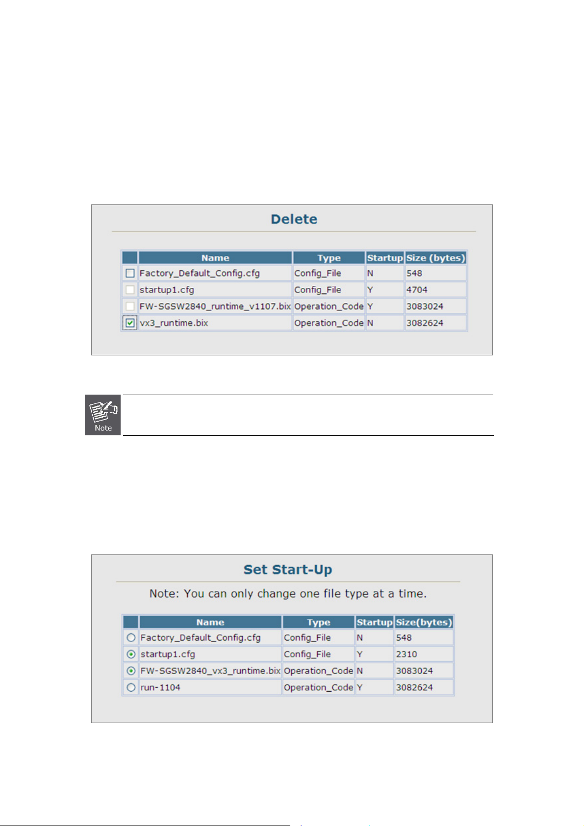
User’s Manual of SGSD-1022 / SGSD-1022P
SGSW-2840 / SGSW-2840P
4.2.6.2 Delete
To delete a file, select the file name from the given list by checking the tick box and then click Apply. The File Delete screen in
Figure 4-2-13 appears.
1. Click System / File Management / Delete.
2. Select the file name from the given list by checking the tick box and click Apply.
Figure 4-2-13 File Delete screenshot
The currently designated startup version cannot be deleted.
4.2.6.3 Set Startup
You can download a file under a new file name and then set it as the startup file, or you can specify the current startup file as the
destination file to directly replace it.
Figure 4-2-14 Set Start-up screenshot
66
Page 67

The page includes the following fields:
Object Description
User’s Manual of SGSD-1022 / SGSD-1022P
SGSW-2840 / SGSW-2840P
• Name
• Type
• Startup
• Size
If you download to a new file name using "tftp to startup-config"," the file is automatically set as the start-up configuration file.
To use the ne w settings, reboot the s ystem via the Reset page.
The file "Factory_Default_Config.cfg" can be copied to the T FTP server, but cannot be
used as the destination on the Managed Switch.
The name of a file stored on the switch.
Indicates either an operation code file, or a configuration file.
Shows if this file is used when the system is started.
The length of the file in bytes.
67
Page 68
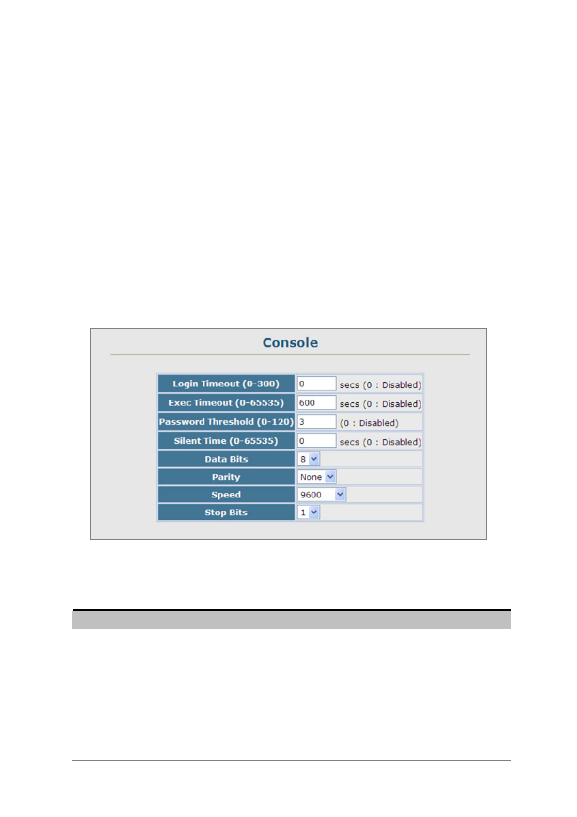
User’s Manual of SGSD-1022 / SGSD-1022P
SGSW-2840 / SGSW-2840P
4.2.7 Line
You can access the onboard configuration program by attaching a VT100 compatible device to the Managed Switch’s serial
console port. Management access through the console port is controlled by various parameters, including a password, timeouts,
and basic communication settings. These parameters can be configured via the Web or CLI interface.
This section has the following options:
■ Console
■ Telnet
Sets console port connection parameters
Sets Telnet connection parameters
4.2.7.1 Console Port Settings
Specify the console port connection parameters as required, then click Apply. The Console Port Settings screen in Figure
4-2-15 appears.
The page includes the following fields:
Object Description
• Login Timeout
• Exec Timeout
Figure 4-2-15 Console port settings screenshot
Sets the interval that the system waits for a user to log into the
CLI. If a login attempt is not detected within the timeout interval, the connection is
terminated for the session.
Range: 0-300 seconds;
Default: 0 seconds
Sets the interval that the system waits until user input is detected. If user input is
not detected within the timeout interval, the current session is terminated.
68
Page 69

User’s Manual of SGSD-1022 / SGSD-1022P
SGSW-2840 / SGSW-2840P
Range: 0-65535 seconds;
Default: 600 seconds
• Password Threshold
• Silent Time
• Data Bits
• Parity
Sets the password intrusion threshold, which limits the number of failed logon
attempts. When the logon attempt threshold is reached, the system interface
becomes silent for a specified amount of time (set by the Silent Time parameter)
before allowing the next logon attempt.
Range: 0-120;
Default: 3 attempts
Sets the amount of time the management console is inaccessible after the
number of unsuccessful logon attempts has been exceeded.
Range: 0-65535;
Default: 0
Sets the number of data bits per character that are interpreted and generated by
the console port. If parity is being generated, specify 7 data bits per character. If
no parity is required, specify 8 data bits per character.
Default: 8 bits
Defines the generation of a parity bit. Communication protocols provided by
some terminals can require a specific parity bit setting. Specify Even, Odd, or
None.
Default: None
• Speed
• Stop Bits
Sets the terminal line’s baud rate for transmit (to terminal) and receive (from
terminal). Set the speed to match the baud rate of the device connected to the
serial port.
Range: 9600, 19200, or 38400 baud;
Default: 9600 bps
Sets the number of the stop bits transmitted per byte.
Range: 1-2;
Default: 1 stop bit
69
Page 70

User’s Manual of SGSD-1022 / SGSD-1022P
SGSW-2840 / SGSW-2840P
4.2.7.2 Telnet Settings
You can access the onboard configuration program over the net work using Telnet (i.e., a virtual terminal). Management access
via Telnet can be enabled / disabl ed and other various parameters set, including the TCP port number, timeouts, and a
password. These parameters can be configured via the web or CLI interface.
The page includes the following fields:
Object Description
• Telnet Status
• Telnet Port Number
• Login Timeout
• Exec Timeout
Figure 4-2-16 Telnet setting screenshot
Enables or disables Telnet access to the s witch.
(Default: Enabled)
Sets the TCP port number for Telnet on the switch.
(Default: 23)
Sets the interval that the system waits for a user to log into the
(Range: 0-300 seconds;
Default: 300 seconds
Sets the interval that the system waits until user input is detected. If user input is
not detected within the timeout interval, the current session is terminated.
Range: 0-65535 seconds;
Default: 600 seconds
• Password Threshold
Sets the password intrusion threshold, which limits the number of failed logon
attempts. When the logon attempt threshold is reached, the system interface
becomes silent for a specified amount of time (set by the Silent Time parameter)
before allowing the next logon attempt.
Range: 0-120;
Default: 3 attempts
70
Page 71

User’s Manual of SGSD-1022 / SGSD-1022P
SGSW-2840 / SGSW-2840P
4.2.8 Log
The switch allows you to control the logging of error messages, including the type of events that are recorded in switch memory,
logging to a remote System Log (syslog) server, and displays a list of recent event messages. This section has the following
options:
■ System Logs
■ Remote Logs
■ SMTP
■ Logs
Sends error messages to a logging process
Configures the logging of messages to a remote logging process
Sends an SMTP client message to a participating server.
Stores and displays error messages
4.2.8.1 System Log Configuration
The system can be configured to send debug and error messages to a logging process. This logging process controls the type
of error messages that are stored in switch memory or sent to a remote syslog server.
The system allows you to enable or disable event logging, and specify which levels are logged to RAM or flash memory.
Severe error messages that are logged to flash memory are permanently stored in the switch to assist in troubleshooting
network problems. Up to 4096 log entries can be stored in the flash memory, with the oldest entries being overwritten first when
the available log memory (256 kilobytes) has been exceeded.
The System Logs page allows you to configure and limit system messages that are logged to flash or RAM memory. The default
is for event levels 0 to 3 to be logged to flash and levels 0 to 6 to be logged to RAM.
The following table lists the event levels of the Managed Switch:
Level Severity Name Description
7
Debug
6
Informational
5
Notice
4
Warning
3
Error
2
Critical
1
Alert
0
Emergency
Debugging messages
Informational messages only
Normal but significant condition, such as cold start
Warning conditions (e.g., return false, unexpected return)
Error conditions (e.g., invalid input, default used)
Critical conditions (e.g., memory allocation, or free memory
error - resource exhausted)
Immediate action needed
System unusable
71
Page 72
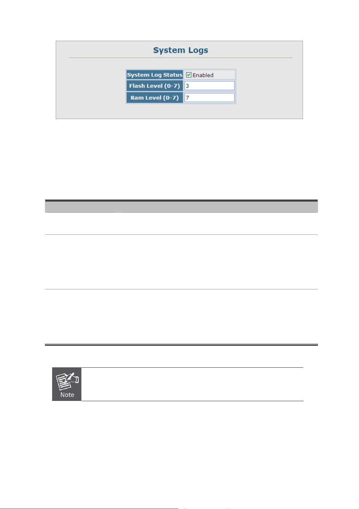
User’s Manual of SGSD-1022 / SGSD-1022P
SGSW-2840 / SGSW-2840P
Figure 4-2-17 System Logs screenshot
1. Click System / Log / System Logs.
2. Specify System Log Status, set the level of event messages to be logged to RAM and flash memory, then click Apply.
The page includes the following fields:
Object Description
• System Log Status
• Flash Level(0-7)
• RAM Level(0-7)
1. There are only Level 2, 5 and 6 error messages for the current firmware release.
Enables/disables the logging of debug or error messages to the logging process.
(Default: Enabled)
Limits log messages saved to the switch’s permanent flash memory for all levels
up to the specified level. For example, if level 3 is specified, all messages from
level 0 to level 3 will be logged to flash.
Range: 0-7,
Default: 3
Limits log messages saved to the switch’s temporary RAM memory for all levels
up to the specified level. For example, if level 7 is specified, all messages from
level 0 to level 7 will be logged to RAM.
Range: 0-7,
Default: 7
2. The Flash Level must be equ al to or less tha n the RAM Level.
72
Page 73

User’s Manual of SGSD-1022 / SGSD-1022P
SGSW-2840 / SGSW-2840P
4.2.8.2 Remote Log Configuration
The Remote Logs page allows you to configure the logging of messages that are sent to syslog servers or other management
stations. You can also limit the event messages sent to only those messages below a specified level.
Figure 4-2-18 Remote Logs screenshot
1. Click System, Log, Remote Logs.
2. To add an IP address to the Host IP List, type the new IP address in the Host IP Address box, and then click Add.
3. To delete an IP address, click the entry in the Host IP List, and then click Remove.
The page includes the following fields:
Object Description
• Remote Log Status
• Logging Facility
Enables/disables the logging of debug or error messages to the remote logging
process.
(Default: Enabled)
Sets the facility type for remote logging of syslog messages. There are eight
facility types specified by values of 16 to 23. The facility type is used by the
syslog server to dispatch log messages to an appropriate service.
The attribute specifies the facility type tag sent in syslog messages. (See RFC
3164.) This type has no effect on the kind of messages reported by the switch.
However, it may be used by the syslog server to process messages, such as
sorting or storing messages in the corresponding database.
73
Page 74

User’s Manual of SGSD-1022 / SGSD-1022P
SGSW-2840 / SGSW-2840P
Range: 16-23,
Default: 23
• Logging Trap
• Host IP List
• Host IP Address
Host IP Address = Syslog Server IP address
Limits log messages that are sent to the remote syslog server for all levels up to
the specified level. For example, if level 3 is specified, all messages from level 0
to level 3 will be sent to the remote server.
Range: 0-7,
Default: 7
Displays the list of remote server IP addresses that receive the syslog messages.
The maximum number of host IP addresses allowed is five.
Specifies a new server IP address to add to the Host IP List.
4.2.8.3 Displaying Log Messages
The Logs page allows you to scroll through the logged system and event messages. The Managed Switch can store up to 2048
log entries in temporary random access memory (RAM; i.e., memory flushed on power reset) and up to 4096 entries in
permanent flash memory.
Figure 4-2-19 System and event logs screenshot
74
Page 75

User’s Manual of SGSD-1022 / SGSD-1022P
SGSW-2840 / SGSW-2840P
4.2.8.4 SMTP E-Mail Alert
To alert system administrators of problems, the Managed Switch can use SMTP (Simple Mail Transfer Protocol) to send email
messages when triggered by logging events of a specified level. The messages are sent to specified SMTP servers on the
network and can be retrieved using POP or IMAP clients.
Figure 4-2-20 SMTP Configuration page screenshot
1. Click System, Log, SMTP.
2. To add an SMTP MAIL Server IP address to the Server IP List, type the new IP address in the Server IP Address box, and
then click Add.
3. To delete an IP address, click the entry in the Server IP List, and then click Remove.
The page includes the following fields:
Object Description
• Admin Status
• Email Source Address
Enables/disables the SMTP function.
(Default: Disabled)
Sets the email address used for the “From” field in alert messages. You may use
a symbolic email address that identifies the switch, or the address of an
administrator responsible for the Managed Switch.
• Severity
Sets the syslog severity threshold level used to trigger alert messages. All events
at this level or higher will be sent to the configured email recipients.
75
Page 76
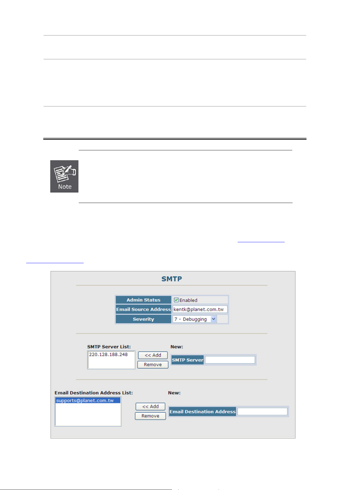
User’s Manual of SGSD-1022 / SGSD-1022P
SGSW-2840 / SGSW-2840P
For example, using Level 7 will report all events from level 7 to level 0.
(Default: Level 7)
• SMTP Server List
• Email Destination
Address List
1. The Managed Switch doesn’t support DNS protocol, to make the SMTP alert receiver to
get the e-mail send by the Managed Switch; the correct SMTP Server ’s IP address has
to be field in the Server List. Check the correct IP address of the Mail Server before
enter the field.
2. It is recommended to send a test e-mail to make sure you can receive the alert mails.
■ Example: SMTP Configuration Sample
Specifies a list of up to three recipient SMTP servers.
The Managed Switch attempts to connect to the other listed servers if the first
fails. Use the New SMTP Server text field and the Add/Remove buttons to
configure the list.
Specifies the email recipients of alert messages. You can specify up to five
recipients. Use the New Email Destination Address text field and the
Add/Remove buttons to configure the list.
In this SMTP example, the Mail server’s IP address is 220.128.188.248. The email account kentk@plant.com.tw is one of the
legal account in the mail domain, once there is a level 7 event occurred, the Managed Switch will send a alert email to
supports@planet.com.tw
Figure 4-2-21 SMTP Configuration sample screenshot
76
Page 77

User’s Manual of SGSD-1022 / SGSD-1022P
SGSW-2840 / SGSW-2840P
4.2.9 UPNP
Universal Plug and Play (UPnP) is a set of protocols that allows devices to connect seamlessly and simplifies the deployment
of home and office networks. UPnP achieves this by issuing UPnP device control protocols designed upon open, Internet-based
communication standards.
The first step in UPnP networking is discovery. When a device is added to the network, the UPnP discovery protocol allows that
device to broadcast its services to control points on the network. Similarly, when a control point is added to the network, the
UPnP discovery protocol allows that control point to search for UPnP enabled devices on the network.
Once a control point has discovered a device its next step is to learn more about the device and its capabilities by retrieving the
device’s description from the URL provided by the device in the discovery message. After a control point has retrieved a
description of the device, it can send actions to the devices service. To do th is, a control point sends a suitable control message
to the control URL for the service (provided in the device description).
When a device is known to the control point, periodic event notification messages are sent. An UPnP description for a service
includes a list of actions the service responds to and a list of variables that model the state of the service at run time.
If a device has a URL for presentation, then the control point can retrieve a page from this URL, load the page into a Web
browser and depending on the capabilities of the page, allows a user to control the device and/or view device status.
UPnP Configuration
This page allows you to enable or disable UPnP, and to set time out values.
Figure 4-2-22 UPnP Configuration page screenshot
Object Description
• UPNP Status
• Advertising Duration
Enables/disables UPnP on the device.
This sets the duration of which a device will advertise its status to the control
point.
Range: 60-86400 seconds;
Default: 100 seconds
77
Page 78

User’s Manual of SGSD-1022 / SGSD-1022P
SGSW-2840 / SGSW-2840P
• TTL Value
Sets the time-to-live (TTL) value for UPnP messages transmitted by the device.
Range: 1-255;
Default: 4
4.2.10 Reset
Reset the Managed Switch. The Managed Switch’s configuration will not be saved automatically; you have to save the
configuration manually before system reboot.
1. Click System, Reset.
2. Click the Reset button to reboot the Mana ged Switch.
3. When prompted, confirm that yo u want reset the switch.
Figure 4-2-23 Reset page screenshot
Figure 4-2-24 Reset page screenshot
When restarting the system, it will always run the Power-On Self-Test.
78
Page 79

User’s Manual of SGSD-1022 / SGSD-1022P
SGSW-2840 / SGSW-2840P
4.2.11 SNTP
Simple Network Time Protocol (SNTP) allows the Managed Switch to set its internal clock based on periodic updates from a
time server (SNTP or NTP). Maintaining an accurate time on the Managed Switch enables the system log to record meaningful
dates and times for event entries. You c an also set the clock manually. If the clock is not set, the Managed Switch will only
record the time from the factory default set at the last bootup.
When the SNTP client is enabled, the switch periodically sends a request for a time update to a configured time server . You can
configure up to three time server IP addresses. The switch will attempt to poll each server in the configured sequence.
4.2.11.1 SNTP Configuration
You can configure the Managed Switch to send time synchronization requests to specific time servers (i.e., client mode), update
its clock based on broadcasts from time servers, or use both methods. When both methods are enabled, the Managed Switch
will update its clock using information broadcast from time servers, but will query the specified server(s) if a broadcast is not
received with the polling interval.
Figure 4-2-25 SNTP Configuration page screenshot
The page includes the following fields:
Object Description
• SNTP Client
Configures the Managed Switch to operate as an SNTP client. This requires at
least one time server to be specified in the SNTP Server field.
(Default: Disabled)
• SNTP Poll Interval
• SNTP Server
Sets the interval between sending requests for a time update from a time server.
(Range: 16-16384 seconds; Default: 16 seconds)
Sets the IP address for up to three time servers. The Managed Switch attempts
to update the time from the first server, if this fails it attempts an update from the
next server in the sequence.
79
Page 80
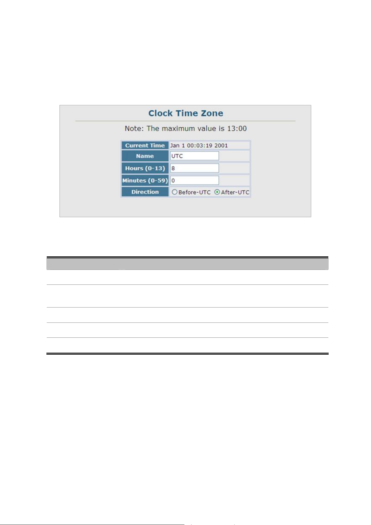
User’s Manual of SGSD-1022 / SGSD-1022P
SGSW-2840 / SGSW-2840P
4.2.11.2 Clock Time Zone
SNTP uses Coordinated Universal Time (or UTC, formerly Greenwich Mean Time, or GMT) based on the time at the Earth's
prime meridian, zero degrees longitude. To display a time corresponding to your local time, you must indicate the number of
hours and minutes your time zone is east (before) or west (after) of UTC.
The page includes the following fields:
Object Description
• Current Time
• Name
• Hours (0-12)
• Minutes (0-59)
• Direction
Figure 4-2-26 Clock Time Zone page screenshot
Displays the current time.
Assigns a name to the time zone.
(Range: 1-29 characters)
The number of hours before/after UTC.
The number of minutes before/after UTC.
Configures the time zone to be before (east) or after (west) UTC
80
Page 81

User’s Manual of SGSD-1022 / SGSD-1022P
SGSW-2840 / SGSW-2840P
4.2.12 LLDP
Link Layer Discovery Protocol (LLDP) is used to discover basic information about neighboring devices on the local broadcast
domain. LLDP is a Layer 2 protocol that uses periodic broadcasts to advertise information about the sending device. Advertised
information is represented in Type Length Value (TLV) format according to the IEEE 802.1ab standard, and can include details
such as device identification, capabilities and configuration settings. LLDP also defines how to store and maintain information
gathered about the neighboring network nodes it discovers.
Link Layer Discovery Protocol - Media Endpoint Discovery (LLDP-MED) is an extension of LLDP intended for managing
endpoint devices such as Voice over IP phones and network switches. The LLDP-MED TLVs advertise information such as
network policy, power, inventory, and device location details. LLDP and LLDP-MED information can be used by SNMP
applications to simplify troubleshooting, enhance network management, and maintain an accurate network topology.
4.2.12.1 LLDP Configuration
Setting LLDP Timing Attributes
Use the LLDP Configuration screen to set attributes for general functions such as globally enabling LLDP on the Managed
Switch, setting the message ageout time, and setting the frequency for broadcasting general advertisements or reports about
changes in the LLDP MIB.
Figure 4-2-27 LLDP Configuration page screenshot
The page includes the following fields:
Object Description
• LLDP
• Transmission Interval
Enables LLDP globally on the switch.
Default: Enabled
Configures the periodic transmit interval for LLDP advertisements.
Range: 5-32768seconds;
81
Page 82

User’s Manual of SGSD-1022 / SGSD-1022P
SGSW-2840 / SGSW-2840P
Default: 30 seconds
This attribute must comply with the following rule:
(Transmission Interval * Hold Time Multiplier) ≤65536, and Transmission Interval
>= (4 * Delay Interval)
• Hold Time Multiplier
• Delay Interval
Configures the time-to-live (TTL) value sent in LLDP advertisements as shown
in the formula below.
Range: 2-10;
Default: 4
The time-to-live tells the receiving LLDP agent how long to retain all information
pertaining to the sending LLDP agent if it does not transmit updates in a timely
manner.
TTL in seconds is based on the following rule:
(Transmission Interval * Holdtime Multiplier) ≤ 65536.
Therefore, the default TTL is 4*30 = 120 seconds.
Configures a delay between the successive transmission of advertisements
initiated by a change in local LLDP MIB variables.
Range: 1-8192 seconds;
Default: 2 seconds
• Reinitialization Delay
• Notification Interval
The transmit delay is used to prevent a series of successive LLDP transmissions
during a short period of rapid changes in local LLDP MIB objects, and to increase
the probability that multiple, rather than single changes, are reported in each
transmission.
This attribute must comply with the rule:
(4 * Delay Interval) ≤Transmission Interval
Configures the delay before attempting to re-initialize after LLDP ports are
disabled or the link goes down.
Range: 1-10 seconds;
Default: 2 seconds
When LLDP is re-initialized on a port, all information in the remote systems LLDP
MIB associated with this port is deleted.
Configures the allowed interval for sending SNMP notifications about LLDP MIB
changes.
Range: 5-3600 seconds;
82
Page 83
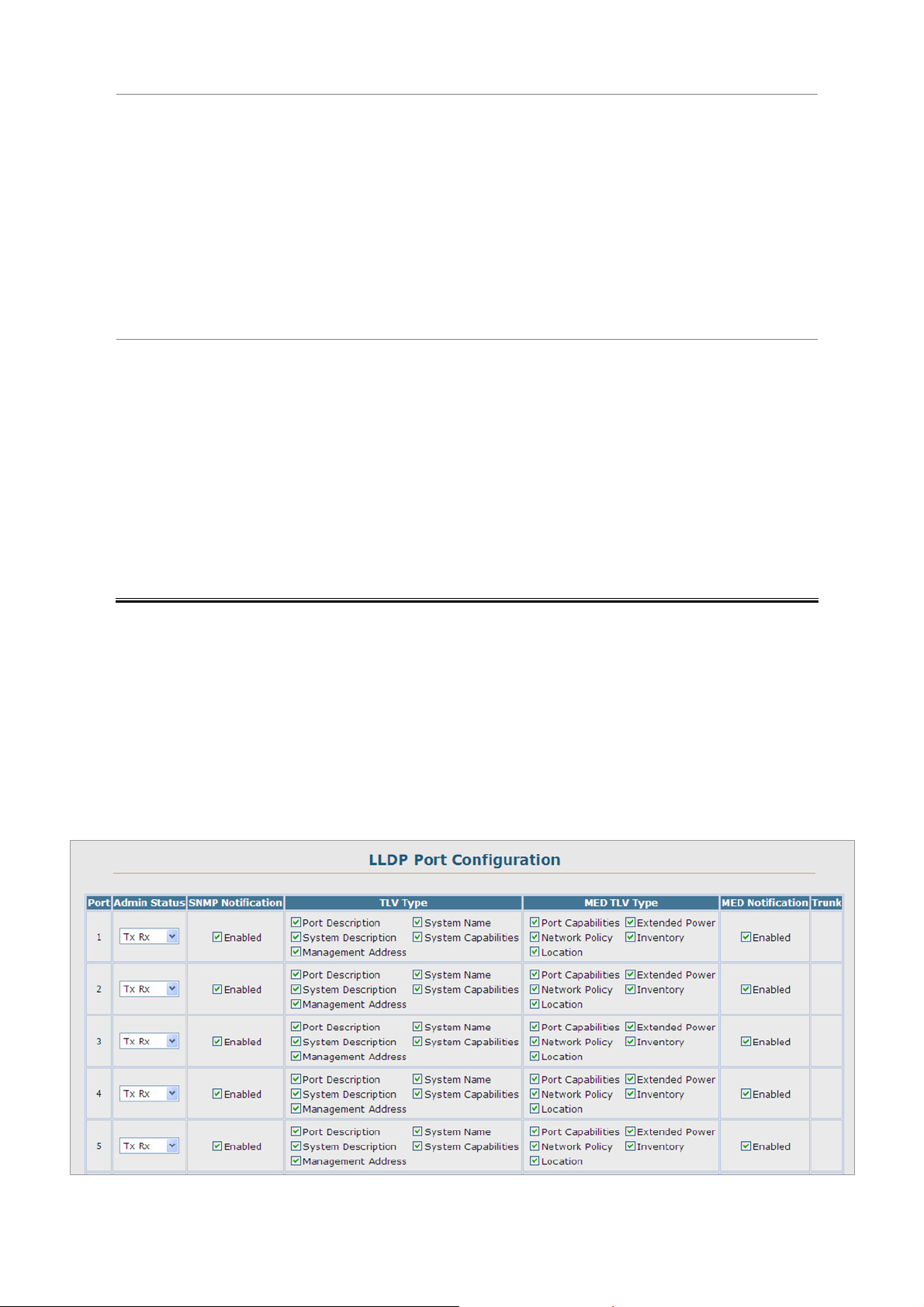
User’s Manual of SGSD-1022 / SGSD-1022P
SGSW-2840 / SGSW-2840P
Default: 5 seconds
This parameter only applies to SNMP applications which use data stored in the
LLDP MIB for network monitoring or management. Information about changes in
LLDP neighbors that occur between SNMP notifications is not transmitted. Only
state changes that exist at the time of a notification are included in the
transmission. An SNMP agent should therefore periodically check the value of
lldpStatsRemTableLastChangeTime to detect any lldpRemTablesChange
notification-events missed due to throttling or transmission loss.
• MED Fast Start Count
Configures the amount of LLDP MED Fast Start LLDPDUs to transmit during the
activation process of the LLDP-MED Fast Start mechanisim.
Range: 1-10 packets;
Default: 4 packets
The MED Fast Start Count parameter is part of the timer which ensures that the
LLDP-MED Fast Start mechanism is active for the port. LLDP-MED Fast Start is
critical to the timely startup of LLDP, and therefore integral to the rapid availability
of Emergency Call Service.
4.2.12.2 LLDP Port Configuration
Use the LLDP Port Configuration to specify the message attributes for individual interfac es, including whether messages are
transmitted, received, or both transmitted and received, whether SNMP notifications are sent, and the type of information
advertised.
Figure 4-2-28 LLDP Port Configuration page screenshot
83
Page 84

The page includes the following fields:
Object Description
User’s Manual of SGSD-1022 / SGSD-1022P
SGSW-2840 / SGSW-2840P
• Admin Status
• SNMP Notification
Enables LLDP message transmit and receive modes for LLDP Protocol Data
Units.
Options:
Tx only
Rx only
TxRx
Disabled
Default: TxRx
Enables the transmission of SNMP trap notifications about LLDP and LLDP-MED
changes. (Default: Enabled) This option sends out SNMP trap notifications to
designated target stations at the interval specified by the Notification Interval in
the preceding section. Trap notifications include information about state changes
in the LLDP MIB (IEEE 802.1AB), the LLDP-MED MIB (ANSI/TIA-1057), or
vendor-specific LLDP-EXT-DOT1 and LLDP-EXT-DOT3 MIBs.
For information on defining SNMP trap destinations. Information about additional
changes in LLDP neighbors that occur between SNMP notifications is not
transmitted. Only state changes that exist at the time of a trap notification are
• TLV Type
included in the transmission. An SNMP agent should therefore periodically check
the value of lldpStatsRemTableLastChangeTime to detect any
lldpRemTables Change notific ation- ev ents missed du e to throttling or
transmission loss.
Configures the information included in the TLV field of advertised messages.
-Port Description – The port description is taken from the ifDescr object in RFC
2863, which includes information about the manufacturer, the product name, and
the version of the interface hardware/software.
-System Description – The system description is taken from the sysDescr
object in RFC 3418, which includes the full name and version identification of the
system's hardware type, software operating system, and networking software.
-Management Address – The management address protocol packet includes
the IPv4 address of the switch. If no management address is available, the
address should be the MAC address for the CPU or for the port sending this
advertisement. The management address TLV may also include information
about the specific interface associated with this address, and an object identifier
indicating the type of hardware component or protocol entity associated with this
address. The interface number and OID are included to assist SNMP
applications in the performance of network discovery by indicating enterprise
specific or other starting points for the search, such as the Interface or Entity
84
Page 85

User’s Manual of SGSD-1022 / SGSD-1022P
SGSW-2840 / SGSW-2840P
MIB.
Since there are typically a number of different addresses associated with a Layer
3 device, an individual LLDP PDU may contain more than one management
address TLV.
Every management address TLV that reports an address that is accessible on a
port and protocol VLAN through the particular port should be accompanied by a
port and protocol VLAN TLV that indicates the VLAN identifier (VID) associated
with the management address reported by this TLV.
-System Name – The system name is taken from the sysName object in RFC
3418, which contains the system’s administratively assigned name. To configure
the system name, see “Displaying System Information” on page 3-12.
-System Capabilities – The system capabilities identifies the primary function(s)
of the system and whether or not these primary functions are enabled. The
information advertised by this TLV is described in IEEE 802.1AB.
• MED TLV Type
Configures the information included in the MED TLV field of advertised
messages.
-Port Capabilities – This option advertises LLDP-MED TLV capabilities, allowing
Media Endpoint and Connectivity Devices to efficiently discover which
LLDP-MED related TLVs are supported on the switch.
-Network Policy – This option advertises network policy configuration
information, aiding in the discovery and diagnosis of VLAN configuration
mismatches on a port. Improper network policy configurations frequently result in
voice quality degradation or complete service disruption.
-Location – This option advertises location identification details.
-Extended Power – This option advertises extended Power-over-Ethernet
capability details, such as power availability from the switch, and power state of
the switch, including whether the switch is operating from primary or backup
power (the Endpoint Device could use this information to decide to enter power
conservation mode). Note that this device does not support PoE capabilities.
-Inventory – This option advertises device details useful for inventory
management, such as manufacturer, model, software version and other
pertinent information.
• MED Notification
• Trunk
Enables the transmission of SNMP trap notifications about LLDP-MED changes.
(Default: Enabled)
Shows if the port is a member of a trunk.
85
Page 86
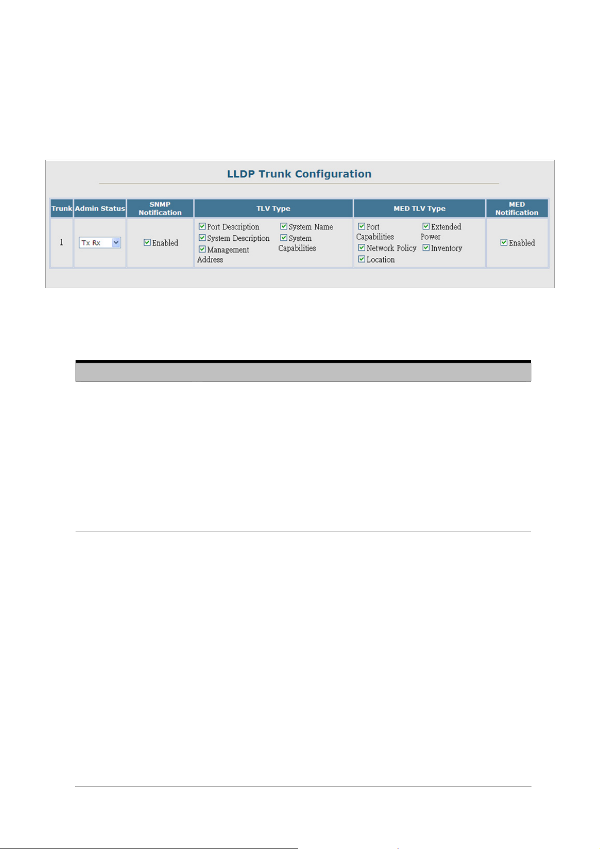
User’s Manual of SGSD-1022 / SGSD-1022P
SGSW-2840 / SGSW-2840P
4.2.12.3 LLDP Trunk Configuration
Use the LLDP Trunk Configuration to specify the message attributes for individual interfaces, including whether messages are
transmitted, received, or both transmitted and received, whether SNMP notifications are sent, and the type of information
advertised.
Figure 4-2-29 LLDP Trunk Configuration page screenshot
The page includes the following fields:
Object Description
• Admin Status
• SNMP Notification
Enables LLDP messages transmit and receive modes for LLDP Protocol Data
Units.
Options:
Tx only
Rx only
TxRx
Disabled
Default: TxRx
Enables the transmission of SNMP trap notifications about LLDP and LLDP-MED
changes.
Default: Enabled
This option sends out SNMP trap notifications to designated target stations at the
interval specified by the Notification Interval in the preceding section. Trap
notifications include information about state changes in the LLDP MIB (IEEE
802.1AB), the LLDP-MED MIB (ANSI/TIA-1057), or vendor-specific
LLDP-EXT-DOT1 and LLDP-EXT-DOT3 MIBs.
For information on defining SNMP trap destinations, see “Specifying Trap
Managers and Trap Types” on page 3-42. Information about additional changes
in LLDP neighbors that occur between SNMP notifications is not transmitted.
Only state changes that exist at the time of a trap notification are included in the
transmission. An SNMP agent should therefore periodically check the value of
86
Page 87

User’s Manual of SGSD-1022 / SGSD-1022P
SGSW-2840 / SGSW-2840P
lldpStatsRemTableLastChangeTime to detect any lldpRemTablesChange
notification-events missed due to throttling or transmission loss.
• TLV Type
Configures the information included in the TLV field of advertised messages.
-Port Description – The port description is taken from the ifDescr object in RFC
2863, which includes information about the manufacturer, the product name, and
the version of the interface hardware/software.
-System Description – The system description is taken from the sysDescr
object in RFC 3418, which includes the full name and version identification of the
system's hardware type, software operating system, and networking software.
-Management Address – The management address protocol packet includes
the IPv4 address of the switch. If no management address is available, the
address should be the MAC address for the CPU or for the port sending this
advertisement. The management address TLV may also include information
about the specific interface associated with this address, and an object identifier
indicating the type of hardware component or protocol entity associated with this
address. The interface number and OID are included to assist SNMP
applications in the performance of network discovery by indicating enterprise
specific or other starting points for the search, such as the Interface or Entity
• MED TLV Type
MIB.
Since there are typically a number of different addresses associated with a Layer
3 device, an individual LLDP PDU may contain more than one management
address TLV.
Every management address TLV that reports an address that is accessible on a
port and protocol VLAN through the particular port should be accompanied by a
port and protocol VLAN TLV that indicates the VLAN identifier (VID) associated
with the management address reported by this TLV.
-System Name – The system name is taken from the sysName object in RFC
3418, which contains the system’s administratively assigned name. To configure
the system name, see “Displaying System Information”.
-System Capabilities – The system capabilities identifies the primary function(s)
of the system and whether or not these primary functions are enabled. The
information advertised by this TLV is described in IEEE 802.1AB.
Configures the information included in the MED TLV field of advertised
messages.
-Port Capabilities – This option advertises LLDP-MED TLV capabilities, allowing
Media Endpoint and Connectivity Devices to efficiently discover which
LLDP-MED related TLVs are supported on the switch.
87
Page 88

User’s Manual of SGSD-1022 / SGSD-1022P
SGSW-2840 / SGSW-2840P
-Network Policy – This option advertises network policy configuration
information, aiding in the discovery and diagnosis of VLAN configuration
mismatches on a port. Improper network policy configurations frequently result in
voice quality degradation or complete service disruption.
-Location – This option advertises location identification details.
-Extended Power – This option advertises extended Power-over-Ethernet
capability details, such as power availability from the switch, and power state of
the switch, including whether the switch is operating from primary or backup
power (the Endpoint Device could use this information to decide to enter power
conservation mode). Note that this device does not support PoE capabilities.
-Inventory – This option advertises device details useful for inventory
management, such as manufacturer, model, software version and other
pertinent information.
• MED Notification
• Trunk
Enables the transmission of SNMP trap notifications about LLDP-MED changes.
(Default: Enabled)
Shows if the port is a member of a trunk.
88
Page 89
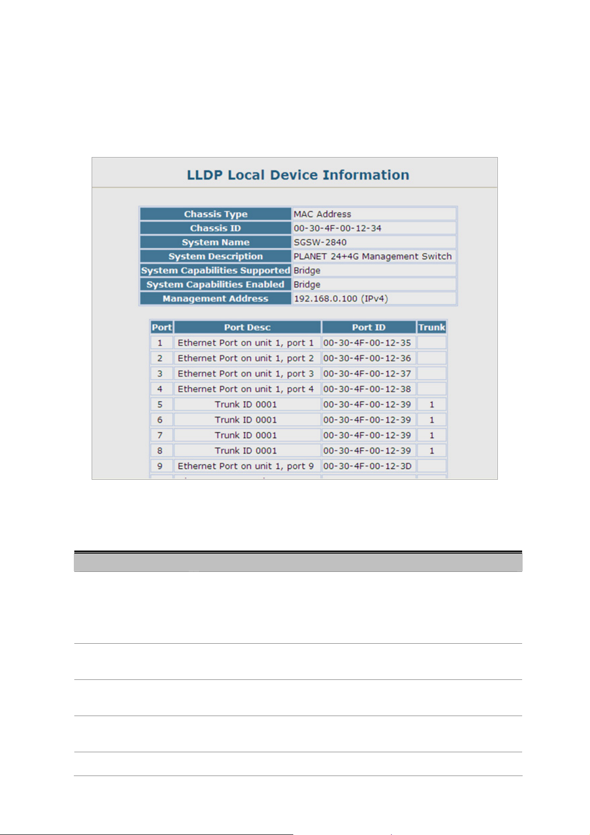
User’s Manual of SGSD-1022 / SGSD-1022P
SGSW-2840 / SGSW-2840P
4.2.12.4 LLDP Local Device Information
Use the LLDP Local Device Information screen to display information about the switch, such as its MAC address, chassis ID,
management IP address, and port information.
Figure 4-2-30 LLDP Local Device Information page screenshot
The page includes the following fields:
Object Description
• Chassis Type
• Chassis ID
• System Name
• System Description
• System Capabilities
Identifies the chassis containing the IEEE 802 LAN entity associated with the
transmitting LLDP agent. There are several ways in which a chassis may be
identified and a chassis ID subtype is used to indicate the type of component
being referenced by the chassis ID field.
An octet string indicating the specific identifier for the particular chassis in this
system.
An string that indicates the system’s administratively assigned name (see
“Displaying System Information”).
A textual description of the network entity. This field is also displayed by the show
system command.
The capabilities that define the primary function(s) of the system.
89
Page 90

User’s Manual of SGSD-1022 / SGSD-1022P
SGSW-2840 / SGSW-2840P
Supported
• System Capabilities
Enabled
• Management Address
ID Basis Reference
Chassis component EntPhysicalAlias when entPhysClass has a value of
Interface alias IfAlias (IETF RFC 2863)
Port component EntPhysicalAlias when entPhysicalClass has a value
MAC address MAC address (IEEE Std 802-2001)
Network address networkAddress
Interface name ifName (IETF RFC 2863)
The primary function(s) of the system which are currently enabled. Refer to the
preceding table.
The management address protocol packet includes the IPv4 address of the
switch. If no management address is available, the address should be the MAC
address for the CPU or for the port sending this advertisement.
‘chassis(3)’ (IETF RFC 2737)
‘port(10)’ or ‘backplane(4)’ (IETF RFC 2737)
Locally assigned locally assigned
Table 4-2-1 Chassis ID Subtype
ID Basis Reference
Other —
Repeater IETF RFC 2108
Bridge IETF RFC 2674
WLAN Access Point IEEE 802.11 MIB
Router IETF RFC 1812
Telephone IETF RFC 2011
DOCSIS cable device IETF RFC 2669 and IETF RFC 2670
End Station Only IETF RFC 2011
Table 4-2-2 System Capabilities
Interface Settings
The attributes listed below apply to both port and trunk interface types. When a trunk is listed, the descriptions appl y to the first
port of the trunk.
90
Page 91
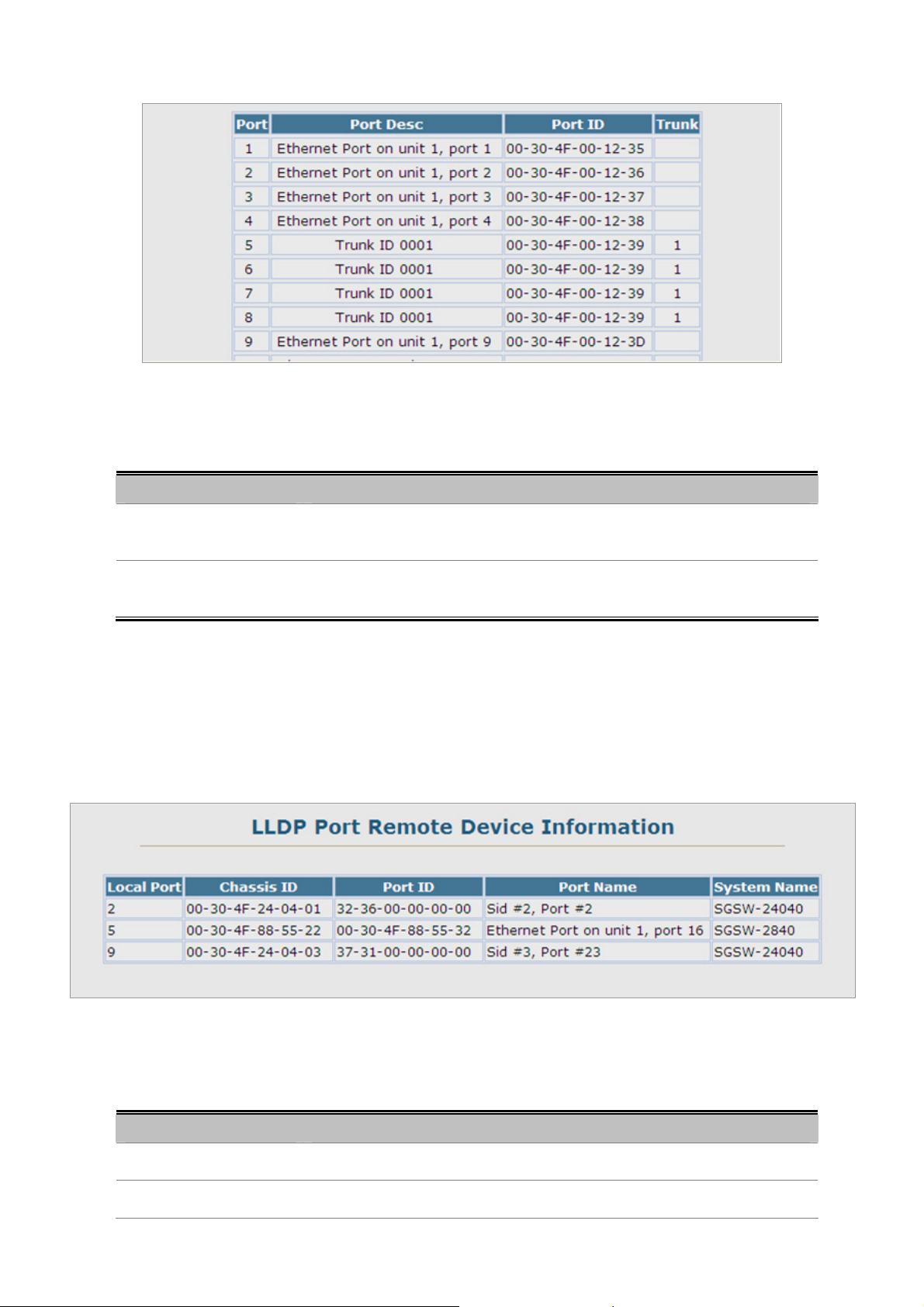
The page includes the following fields:
Object Description
User’s Manual of SGSD-1022 / SGSD-1022P
SGSW-2840 / SGSW-2840P
Figure 4-2-31 Interface Settings page screenshot
• Port Description
• Port ID
A string that indicates the port’s description. If RFC 2863 is implemented, the
ifDescr object should be used for this field.
A string that contains the specific identifier for the port from which this LLDPDU
was transmitted.
4.2.12.5 Remote Port Information
Use the LLDP Remote Port/Trunk Information screen to display information about devices connected directly to the switch’s
ports which are advertising information through LLDP.
The page includes the following fields:
Object Description
• Local Port
• Chassis ID
Figure 4-2-32 LLDP Configuration page screenshot
The local port to which a remote LLDP-capable device is attached.
An octet string indicating the specific identifier for the particular chassis in this
91
Page 92
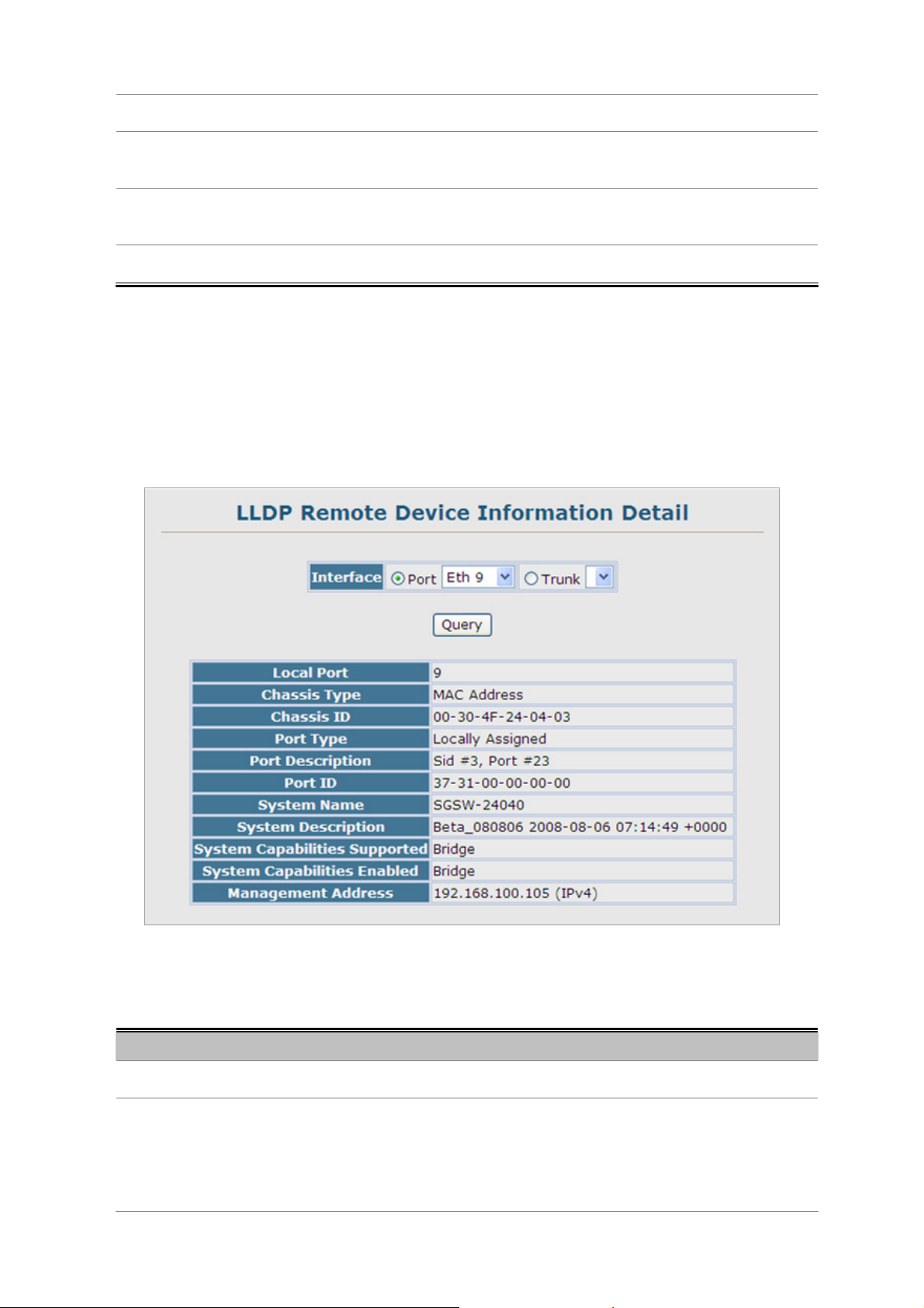
User’s Manual of SGSD-1022 / SGSD-1022P
SGSW-2840 / SGSW-2840P
system.
• Port ID
• Port Name
• System Name
A string that contains the specific identifier for the port from which this LLDPDU
was transmitted.
A string that indicates the port’s description. If RFC 2863 is implemented, the
ifDescr object should be used for this field.
An string that indicates the system’s administratively assigned name.
4.2.12.6 LLDP Remote Information Detail
Use the LLDP Remote Information Details screen to display detailed information about an LLDP-enabled device connected to a
specific port on the local switch.
The page includes the following fields:
Object Description
• Local Port
• Chassis Type
Figure 4-2-33 LLDP Configuration page screenshot
The local port to which a remote LLDP-capable device is attached.
Identifies the chassis containing the IEEE 802 LAN entity associated with the
transmitting LLDP agent. There are several ways in which a chassis may be
identified and a chassis ID subtype is used to indicate the type of component
being referenced by the chassis ID field.
92
Page 93

User’s Manual of SGSD-1022 / SGSD-1022P
SGSW-2840 / SGSW-2840P
(See Table 4-2-1, “Chassis ID Subtype,)
• Chassis ID
• Port Type
• System Name
• System Description
• System Capabilities
Supported
• System Capabilities
Enabled
• Management Address
An octet string indicating the specific identifier for the particular chassis in this
system.
Indicates the basis for the identifier that is listed in the Port ID field.
An string that indicates the system’s administratively assigned name.
A textual description of the network entity.
The capabilities that define the primary function(s) of the system.
(See Table 4-2-2, “System Capabilities,)
The primary function(s) of the system which are currently enabled. Refer to the
preceding table.
(See Table 4-2-2, “System Capabilities,)
The IPv4 address of the remote device. If no management address is available,
the address should be the MAC address for the CPU or for the port sending this
advertisement.
ID Basis Reference
Interface alias IfAlias (IETF RFC 2863)
Chassis component EntPhysicalAlias when entPhysClass has a value of
‘chassis(3)’ (IETF RFC 2737)
Port component EntPhysicalAlias when entPhysicalClass has a value
‘port(10)’ or ‘backplane(4)’ (IETF RFC 2737)
MAC address MAC address (IEEE Std 802-2001)
Network address networkAddress
Interface name ifName (IETF RFC 2863)
Agent circuit ID agent circuit ID (IETF RFC 3046)
Locally assigned locally assigned
Table 4-2-3 Port ID Subtype
93
Page 94

User’s Manual of SGSD-1022 / SGSD-1022P
SGSW-2840 / SGSW-2840P
4.2.12.7 LLDP Device Statistics
Use the LLDP Device Statistics screen to general statistics for LLDP-capable devices attached to the switch, and for LLDP
protocol messages transmitted or received on all local interfaces.
The page includes the following fields:
Object Description
• Neighbor Entries List
Last Updated
• New Neighbor Entries
Count
• Neighbor Entries
Deleted Count
• Neighbor Entries
Dropped Count
• Neighbor Entries
Age-out Count
Figure 4-2-34 LLDP Configuration page screenshot
The time the LLDP neighbor entry list was last updated.
The number of LLDP neighbors for which the remote TTL has not yet expired.
The number of LLDP neighbors which have been removed from the LLDP remote
systems MIB for any reason.
The number of times which the local remote database dropped an LLDPDU
because of insufficient resources.
The number of times that a neighbor’s information has been deleted from the
LLDP remote systems MIB because the remote TTL timer has expired.
94
Page 95

User’s Manual of SGSD-1022 / SGSD-1022P
SGSW-2840 / SGSW-2840P
4.2.12.8 LLDP Device Statistics Details
Use the LLDP Device Statistics Details screen to display detailed statistics for LLDP-capable devices attached to specific
interfaces on the Managed Switch.
Figure 4-2-35 LLDP Device Statistics Details page screenshot
The page includes the following fields:
Object Description
• Frames Discarded
• Frames Invalid
• Frames Received
• Frames Sent
• TLVs Unrecognized
• TLVs Discarded
• Neighbor Ageouts
Number of frames discarded because they did not conform to the general
validation rules as well as any specific usage rules defined for the particular TLV.
A count of all LLDPDUs received with one or more detectable errors.
Number of LLDP PDUs received.
Number of LLDP PDUs transmitted.
A count of all TLVs not recognized by the receiving LLDP local agent.
A count of all LLDPDUs received and then discarded due to insufficient memory
space, missing or out-of-sequence attributes, or any other reason.
A count of the times that a neighbor’s information has been deleted from the
LLDP remote systems MIB because the remote TTL timer has expired.
95
Page 96

User’s Manual of SGSD-1022 / SGSD-1022P
SGSW-2840 / SGSW-2840P
4.3 Simple Network Management Protocol
Simple Network Management Protocol (SNMP) is a communication protocol designed specifically for managing devices on a
network. Equipment commonly managed with SNMP includes switches, routers and host computers. SNMP is typically used to
configure these devices for proper operation in a network environment, as well as to monitor them to evaluate performance or
detect potential problems.
Managed devices supporting SNMP contain software, which runs locally on the device and is referred to as an agent. A defined
set of variables, known as managed objects, is maintained by the SNMP agent and used to manage the device. These objects
are defined in a Management Information Base (MIB) that provides a standard presentation of the information controlled by
the agent. SNMP defines both the format of the MIB specifications and the protocol used to access this information over the
network.
The Managed Switch includes an onboard agent that supports SNMP versions 1, 2c, and 3. This agent continuously monitors
the status of the Managed Switch hardware, as well as the traffic passing through its ports. A network management station can
access this information using software such as HP OpenView. Access to the onboard agent from clients using SNMP v1 and v2c
is controlled by community strings. To communicate with the switch, the management station must first submit a valid
community string for authentication.
Access to the switch using from clients using SNMPv3 provides additional security features that cover message integrity,
authentication, and encryption; as well as controlling user access to specific areas of the MIB tree.
The SNMPv3 security structure consists of security models, with each model having it’s own security levels. There are three
security models defined, SNMPv1, SNMPv2c, and SNMPv3. Users are assigned to “groups” that are defined by a security
model and specified security levels. Each group also has a defined security access to set of MIB objects for reading and writing,
which are known as “views.” The switch has a default view (all MIB objects) and default groups defined for security models v1
and v2c. The following table shows the security models and levels available and the system default settings.
Model Level Group Read View Write View Notify View Security
v1 noAuthNoPriv public (read only) defaultview none none Community string only
v1 noAuthNoPriv private(read/write) defaultview defaultview none Community string only
v1 noAuthNoPriv user defined user defined user defined user defined Community string only
v2c noAuthNoPriv public (read only) defaultview none none Community string only
v2c noAuthNoPriv private (read/write) defaultview defaultview none Community string only
v2c noAuthNoPriv user defined user defined user defined user defined Community string only
v3 noAuthNoPriv user defined user defined user defined user defined A user name match onl y
v3 AuthNoPriv user defined user defined user defined user defined Provides user
authentication via MD5
or SHA algorithms
96
Page 97
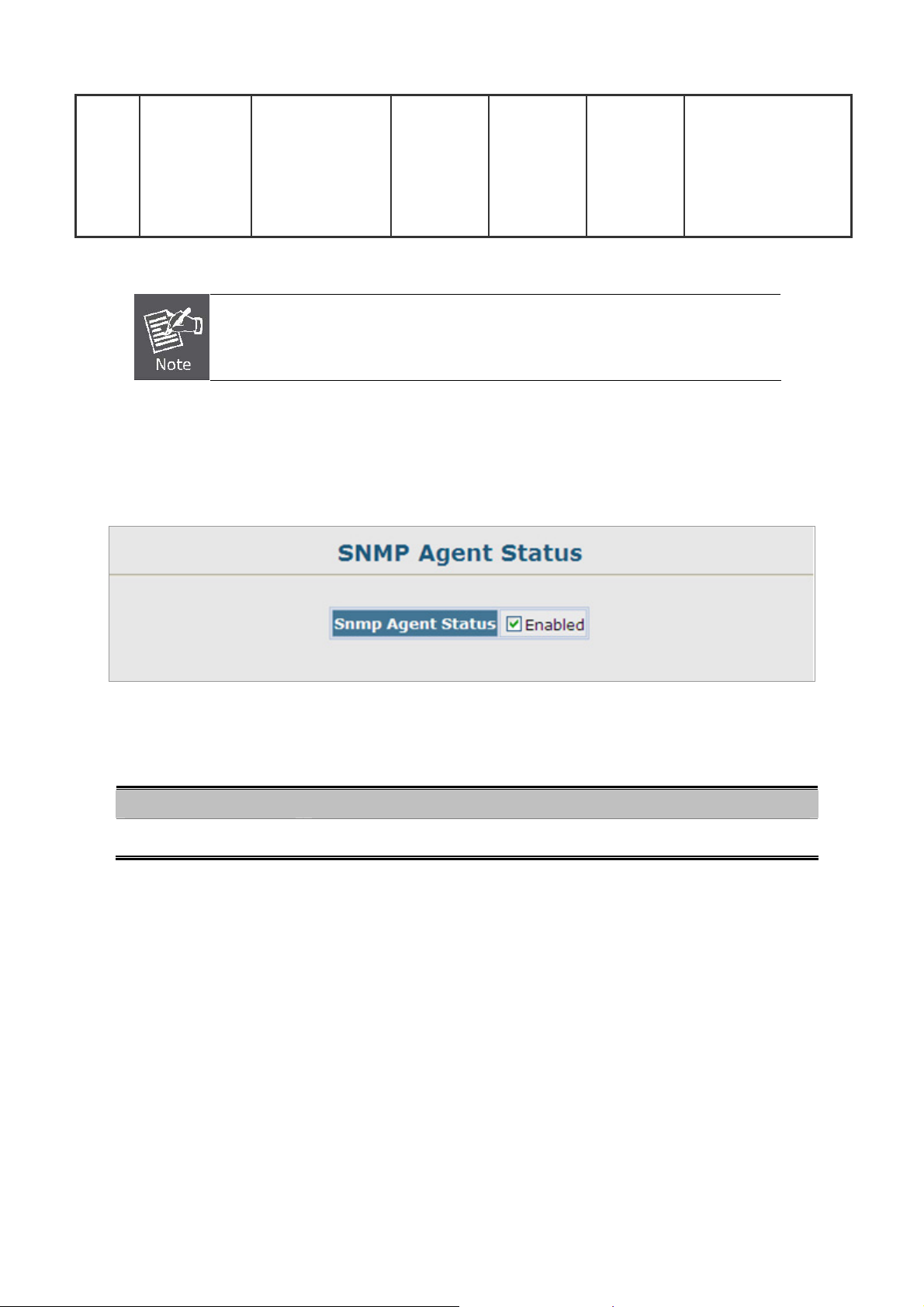
User’s Manual of SGSD-1022 / SGSD-1022P
SGSW-2840 / SGSW-2840P
v3 AuthPriv user defined user defined user defined user defined Provides user
authentication via MD5
or SHA algorithms and
data privacy using DES
56-bit encryption
The predefined default groups and view can be deleted from the system. You can then
define customized groups and views for the SNMP clients that require access.
4.3.1 SNMP Agent Status
Enable SNMP service for all management clients. (i.e., versions 1, 2c or 3).
Figure 4-3-1 SNMP Agent Status page screenshot
The page includes the following fields:
Object Description
• Snmp Agent Status
Enable / Disable SNMP on the Managed Switch
4.3.2 SNMP Configuration
Use this page to configure the community strings authorized for management access, and to specify the trap managers that will
receive SNMP notifications or trap messages.
4.3.2.1 SNMP Community
All community strings used for IP Trap Managers should be listed in this table. Up to five community strings may be entered. For
security reasons, you should consider removing the default strings.
97
Page 98

User’s Manual of SGSD-1022 / SGSD-1022P
SGSW-2840 / SGSW-2840P
Figure 4-3-2 SNMP Configuration page screenshot
1. Click SNMP, Configuration.
2. Add new communit y strings as required, select the access rights from the Access Mode drop-down list, then click Add.
The page includes the following fields:
Object Description
• SNMP Community
Capability
• Community String
• Access Mode
The switch supports up to five community strings.
A community string that acts like a password and permits access to the SNMP
protocol.
Default strings: “public” (read-only), “private” (read/write)
Range: 1-32 characters, case sensitive
Specifies the access rights for the community string:
• Read-Only – Authorized management stations are only able to retrieve MIB
objects.
• Read/Write – Authorized management stations are able to both retrieve and
modify MIB objects.
4.3.2.2 SNMP Trap Management
Traps indicating status changes are issued by the switch to specified trap managers. You must specify trap managers so that
key events are reported by this switch to your management station (using network management platforms such as HP
OpenView). You can specify up to five management stations that will receive authentication failure messages and other trap
messages from the Managed Switch.
- You can enab le or disable authentication messages via the Web interface.
- You can enable or disable authentication messages, link-up-down messages, or all notification types via the CLI.
98
Page 99
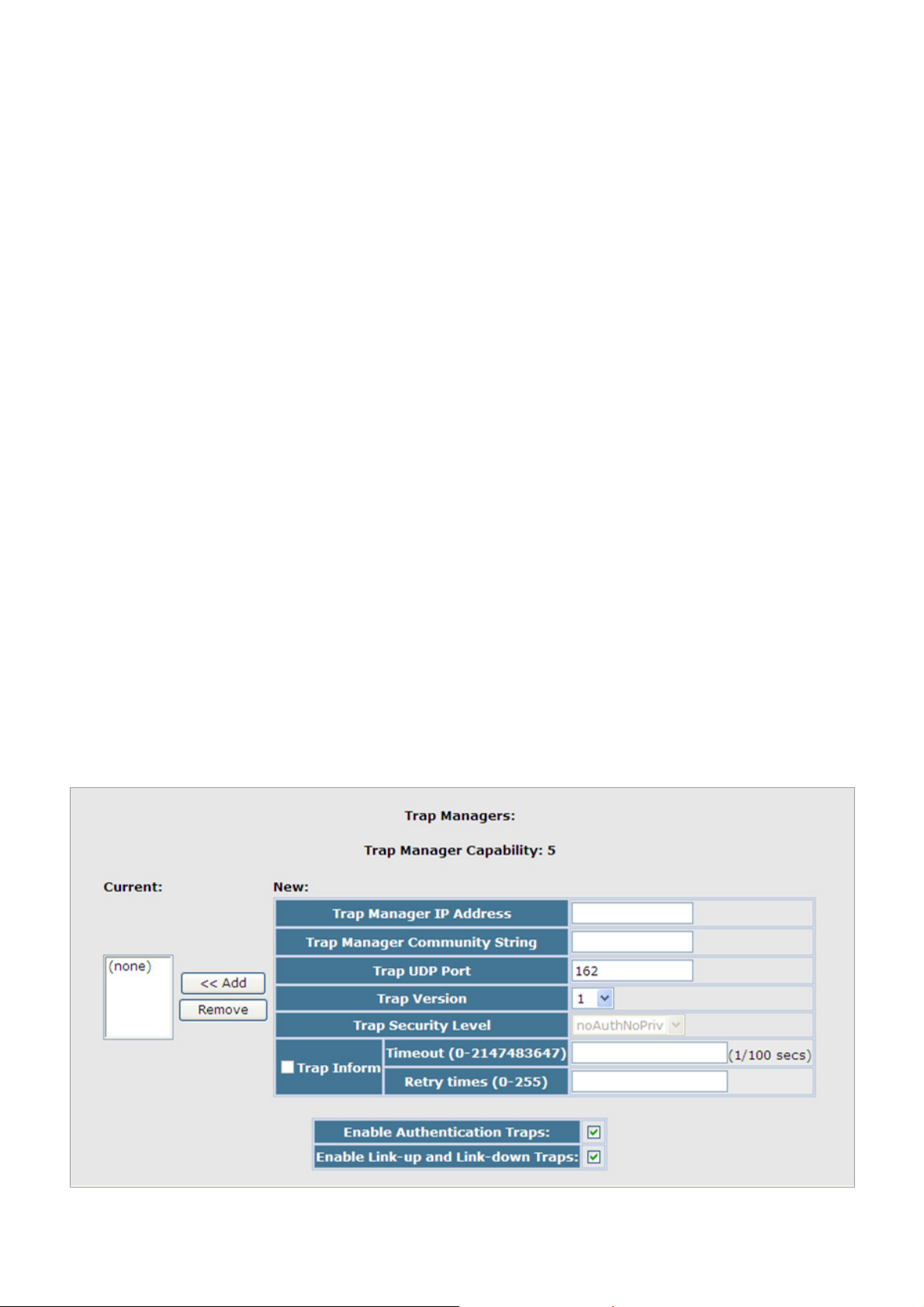
User’s Manual of SGSD-1022 / SGSD-1022P
SGSW-2840 / SGSW-2840P
If you specify an SNMP Ve rsion 3 host, then the “T rap Manager Community S tring” is interpreted as an SNMP user name. If you
use V3 authentication or encryption options (authNoPriv or authPriv), the user name must first be defined in the SNMPv3 Users
page. Otherwise, the authentication password and/or privacy password will not exist, and the switch will not authorize SNMP
access for the host. However, if you specify a V3 host with the no authentication (noAuth) option, an SNMP user account will be
automatically generated, and the switch will authorize SNMP access for the host.
Notifications are issued by the sw itch a s trap messages by default. The recipient of a trap message does not send a response to
the switch. Traps are therefore not as reliable as inform messages, which include a request for acknowledgement of receipt.
Informs can be used to ensure that critical information is received by the host. However, note that informs consume more
system resources because they must be kept in memory until a response is received. Informs also add to network traffic. You
should consider these effects when deciding whether to issue notifications as traps or informs.
To send an inform to a SNMPv2c host, compl ete these steps:
1. Enable the SNMP agent.
2. Enable trap informs as described in the following pages.
3. Create a view with the required notification messages.
4. Create a group that includes the required notify view.
To send an inform to a SNMPv3 host, complete these steps:
1. Enable the SNMP agent.
2. Enable trap informs as described in the following pages.
3. Create a view with the required notification messages.
4. Create a group that includ es the required notify view.
5. Specify a remote engine ID where the user resides.
6. Then configure a remote user.
Figure 4-3-3 SNMP Trap Management page screenshot
99
Page 100

User’s Manual of SGSD-1022 / SGSD-1022P
SGSW-2840 / SGSW-2840P
1. Click SNMP, Configuration.
2. Enter the IP address and community string for each management station that will receive trap messages, specify the UDP
port, trap version, trap security level (for v3 clients), trap inform settings (for v2c/v3 clients), and then click Add.
3. Select the trap types required using the check boxes for Authentication and Link-up/down traps, and then click Apply.
The page includes the following fields:
Object Description
• Trap Manager Capability
• Current
• Trap Manager IP Address
• Trap Manager Community
String
• Trap UDP Port
• Trap Version
• Trap Security Level
This switch supports up to five trap managers.
Displays a list of the trap managers currently configured.
IP address of a new management station to receive notification message
(i.e., the targeted recipient).
Specifies a valid community string for the new trap manager entry. Though you
can set this string in the Trap Managers table, we recommend that you define
this string in the SNMP Configuration page (for Version 1 or 2c clients), or define
a corresponding “User Name” in the SNMPv3 Users page (for Version 3 clients).
(Range: 1-32 characters, case sensitive)
Specifies the UDP port number used by the trap manager.
(Default: 162)
Specifies whether to send notifications as SNMP v1, v2c, or v3 traps.
(Default: v1)
When trap version 3 is selected, you must specify one of the following security
levels.
• noAuthNoPriv
There is no authentication or encryption used in SNMP
communications.
• AuthNoPriv
• AuthPriv
(Default: noAuthNoPriv)
• Trap Inform
• Enable Authentication
Notifications are sent as inform messages. Note that this option is only available
for version 2c and 3 hosts. (Default: traps are used)
Timeout
Retry
times –receipt.
Issues a notification message to specified IP trap managers whenever an invalid
SNMP communications use authentication, but the data is
not encrypted (only available for the SNMPv3 security
model).
SNMP communications use both authentication and
encryption (only available for the SNMPv3 security model).
The number of seconds to wait for an acknowledgment
The maximum number of times to resend an inform
before resending an inform message.
message if the recipient does not acknowledge.
Range: 0-2147483647 cent seconds;
Range: 0-255;
Default: 1500 cent seconds
Default: 3
100
 Loading...