

Page 1

User’s Manual
ICS-100 / ICS-102 / ICS-102S15
RS-232/RS-422/RS-485
over
100Base-FX / 10/100Base-TX
Media Converter
Page 2

User’s Manual of ICS-10x
Trademarks
Copyright © PLANET Technology Corp. 2008.
Contents subject to which revision without prior notice.
PLANET is a registered trademark of PLANET Technology Corp. All other trademarks belong to their respective owners.
Disclaimer
PLANET Technology does not warrant that the hardware will work properly in all environments and applications, and
makes no warranty and representation, either implied or expressed, with respect to the quality, performance,
merchantability, or fitness for a particular purpose.
PLANET has made every effort to ensure that this User's Manual is accurate; PLANET disclaims liability for any
inaccuracies or omissions that may have occurred.
Information in this User's Manual is subject to change without notice and does not represent a commitment on the part of
PLANET. PLANET assumes no responsibility for any inaccuracies that may be contained in this User's Manual. PLANET
makes no commitment to update or keep current the information in this User's Manual, and reserves the right to make
improvements to this User's Manual and/or to the products described in this User's Manual, at any time without notice.
If you find information in this manual that is incorrect, misleading, or incomplete, we would appreciate your comments and
suggestions.
FCC Warning
This equipment has been tested and found to comply with the limits for a Class B digital device, pursuant to Part 15 of the
FCC Rules. These limits are designed to provide reasonable protection against harmful interference when the equipment is
operated in a commercial environment. This equipment generates, uses, and can radiate radio frequency energy and, if not
installed and used in accordance with the Instruction manual, may cause harmful interference to radio communications .
Operation of this equipment in a residential area is likely to caus e harmful interference in which case the user will be
required to correct the interference at whose own expense.
CE Mark Warning
This is a Class A product. In a domestic environment, this product may cause radio interference, in which case the user
may be required to take adequate measures.
WEEE Warning
To avoid the potential effects on the environment and human health as a result of the presenc e of
hazardous substances in electrical and electronic equipment, end users of electrical and electronic
equipment should understand the meaning of the crossed-out wheeled bin symbol. Do not dispose of
WEEE as unsorted municipal waste and have to collect such WEEE separately.
Revision
PLANET RS-232/RS-422/RS-485 over 10/100Base-TX/100Base-FX Media Converter User's Manual
FOR MODELS: ICS-100 / ICS-102 / ICS-102S15
REVISION: 1.1 (APRIL.2008)
Part No.: 2080-AA3600-000
-2-
Page 3

User’s Manual of ICS-10x
TABLE OF CONTENTS
1. INTRODUCTION .............................................................................................................1
1.1 PACKAGE CONTENTS .................................................................................................................................. 1
1.2 HOW TO USE THIS MANUAL......................................................................................................................... 1
1.3 PRODUCT DESCRIPTION.............................................................................................................................. 2
1.4 APPLICATIONS ............................................................................................................................................ 2
1.5 PRODUCT FEATURES .................................................................................................................................. 4
1.6 PRODUCT SPECIFICATION ...................................................................................................................5
2. INSTALLATION ..............................................................................................................7
2.1 HARDWARE DESCRIPTION ........................................................................................................................... 7
2.1.1 Product Layout....................................................................................................................................................7
2.1.2 LED Indicators.....................................................................................................................................................9
2.1.3 DB9 Pin Define....................................................................................................................................................9
2.1.4 ICS-10X Rear Panel............................................................................................................................................9
2.2 INSTALL THE CONVERTER.......................................................................................................................... 10
2.2.1 Stand-alone Installation.....................................................................................................................................10
2.2.2 Chassis Installation and Rack Mounting ...........................................................................................................11
3. MANAGEMENT.............................................................................................................13
3.1 OVERVIEW................................................................................................................................................ 13
3.2 REQUIREMENTS........................................................................................................................................ 13
3.3 MANAGEMENT METHODS........................................................................................................................... 14
3.3.1 Web Management.............................................................................................................................................14
3.3.2 Login the Media converter.................................................................................................................................14
4. WEB CONFIGURATION...............................................................................................16
4.1 MAIN MENU.............................................................................................................................................. 16
4.2 SYSTEM ................................................................................................................................................... 17
4.2.1 System Information...........................................................................................................................................17
4.2.2 Password Setting..............................................................................................................................................18
4.2.3 Firmware upgrade.............................................................................................................................................19
4.2.4 Factory Default..................................................................................................................................................21
4.2.5 System Reboot..................................................................................................................................................21
4.3 NETWORK CONFIGURATION....................................................................................................................... 22
4.4 OPERATION MODE .................................................................................................................................... 23
4.4.1 TCP server mode..............................................................................................................................................23
4.4.2 TCP Client mode...............................................................................................................................................29
4.4.3 UDP Client mode ..............................................................................................................................................30
4.4.4 Virtual COM mode.............................................................................................................................................31
4.4.5 Telnet Server mode...........................................................................................................................................37
4.4.6 Pair Connection– Local mode...........................................................................................................................42
4.4.7 Pair Connection – Remote mode......................................................................................................................43
-3-
Page 4

User’s Manual of ICS-10x
4.5 SERIAL PORT CONFIGURATION .................................................................................................................. 47
5. SOFTWARE VCOM UTILITY.......................................................................................49
5.1 INSTALLING THE VCOM UTILITY ................................................................................................................ 49
5.2 SEARCH THE DEVICE................................................................................................................................. 51
5.3 VIRTUAL COM.......................................................................................................................................... 51
APPENDIX A.....................................................................................................................54
A.1 PLANET SMART DISCOVERY UTILITY ....................................................................................................... 54
A.2 DEVICE‘S RJ-232/RS-422/RS-485 PIN ASSIGNMENTS.............................................................................. 55
A.3 DEVICE‘S RJ-45 PIN ASSIGNMENTS .......................................................................................................... 55
A.4 RJ-45 CABLE PIN ASSIGNMENT.................................................................................................................. 56
A.5 FIBER OPTICAL CABLE CONNECTION PARAMETER...................................................................................... 57
A.6 POWER INFORMATION............................................................................................................................... 57
-4-
Page 5

User’s Manual of ICS-10x
1. INTRODUCTION
Thank you for purchasing PLANET Serial over Fast Ethernet Media Converter – ICS-10x series. Terms of “Serial Media
Converter” means the products mentioned titled in the cover page of this User’s manual
1.1 Package Contents
Open the box of the Serial Media Converter and carefully unpack it. The box should contain the following items:
Check the contents of your package for following parts:
Serial Media Converter x1
CD-ROM user's manual x1
Quick installation guide x1
External 5VDC / 2.5 A pow er adapter x 1
If any of these are missing or damaged , please contact your dealer i mmediately, if po ssible, retain the carton including the
original packing material, and use them against to repack the product in case there is a need to return it to us for repair.
1.2 How to Use This Manual
This Media Convert e r Us er Man u al i s st r uc tu r ed as fo l lows:
Section 2, Installation
It explains the functions of ICS-10x and how to physically install the ICS-10x.
Section 3, Management
The chapter explains how to manage the converter by Web interface.
Section 4, Web Configuration
It contains information about the Smart function of ICS-10x.
Section 5, So ftware VCOM Utility
It explains the software VCOM how to use with the operation Virtual COM.
Appendices
It contains cable information of ICS-10x.
-1-
Page 6
User’s Manual of ICS-10x
1.3 Product Description
The Web-Smart ICS-10x series Media Converter / Device Server provide to converts Serial RS-232 / RS-422 / RS-485
communication interface over Fast Ethernet networking. There are RJ-45/SC connectors and
single-mode/multi-mode media for your needs. Ethernet signal that allows two types of segments to connect easily,
efficiently and inexpensively. This converter can be used as a stand-alone unit or as a slide-in module to the PLANET
Media Converter Chassis (MC-700, MC-1000 and MC-1500). It’s time saving expense for user and SI, no need to
replace the existing Serial equipment and software system.
It extends the distance of deploying Serial equipments and hosts. The selectable fiber-Optic wires on the basis of
distance are flexibly provided. Therefore, this product will perfectly satisfy the di verse demands while providing reliable
and efficient network solutions based on the distance and budgets of installation.
The ICS-10x make connected Serial equipment becomes IP-based. That also makes them be able to connect to a
TCP/IP networking immediately. Each Web-Smart converter is able to manage through the Web Interface. The powerful
Web-Smart Media Converter supports Application mode, Serial operation mode connect alarm and IP address, etc.
Management function helps reduce the amount of valuable time that a network administrator spends detecting and
locating network problems, otherwise it requires visual inspection of cabling and equipment. Multiple connection op tions
for large networking environment are available as well.
1.4 Applications
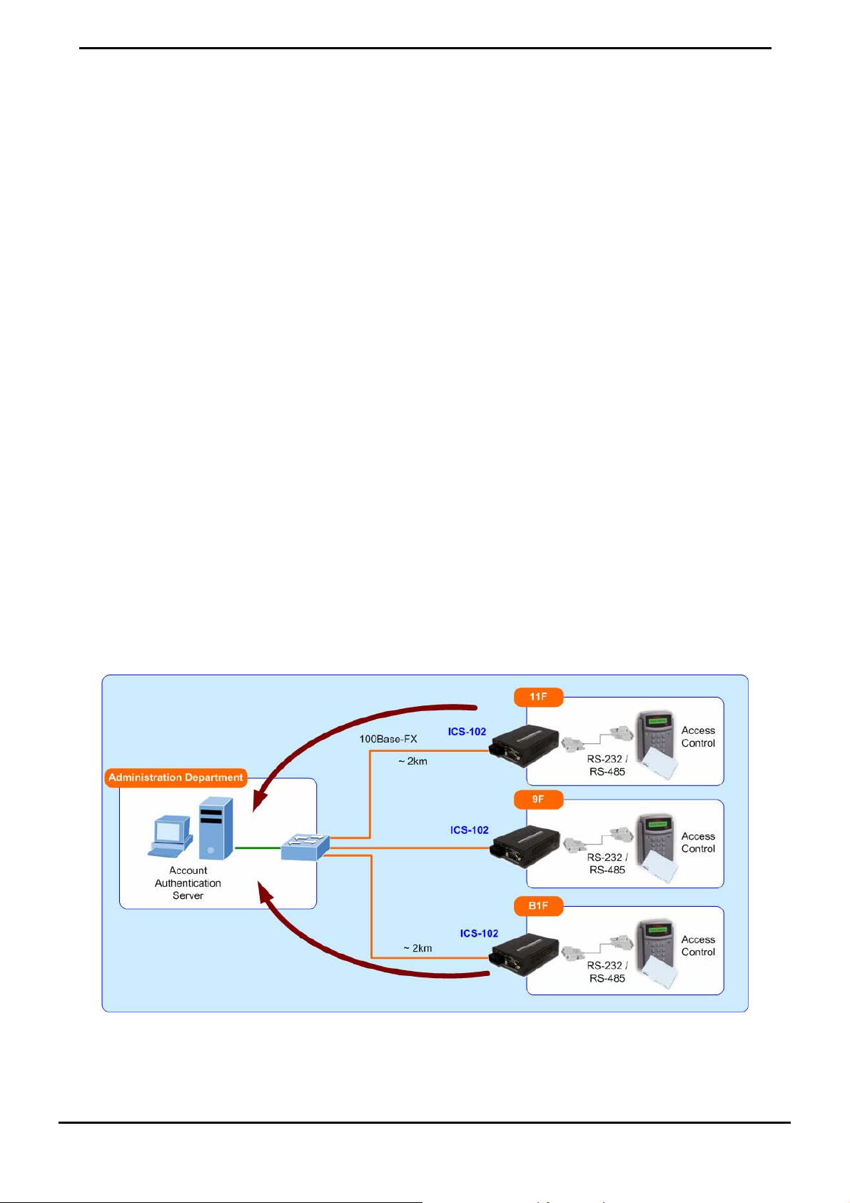
Access Control System – traditional installation
Most of the enterprise and government use access control plate a n d Mifare or RFID to authorize the entrance identity.
With traditional deploy, access control machine use RS-232 or R S-485 serial inte rface and cabl es connect to login server.
With connection to ICS-10x Serial over Fast Ethernet Converter, the access control machine is able to be extend over
longer distances via fiber optical interface. The distance can be up to 20 km in a local ra nge. Or the ICS-10x can be lin ked
to a xDSL router to get the internet access capability; the access control can be set and monitored over the internet.
Figure 1-1 Serial Converter for Access Control System application
-2-
Page 7

User’s Manual of ICS-10x
Process Control
To monitor, configure and manage the Robot conveyer including other machines in a manufactu ring, PLC (Programmable
Logical Control) is required. The PLC is used to drive above the manufacturing machines process. The ICS-10x can be se t
to TCP Server mode and connect the PLC. The administrator can configure and set command settings through Fast
Ethernet intranet to control the PLC , the administra tor and w orkstation . There i s no need to be alway s sets by the side of
the I/O machine.
Figure 1-2 Serial Converter for factory PLC application
RTU Data Collect – UDP Mode
Connect with RTU (Remote Terminal Unit) to collect and monitor the data of waves, sig nal and pow er utilizati on. ICS-10x
can be used to set-up UDP mode and send data over Fast Ethernet to Local server or over internet to remote server
automatically.
Figure 1-3 Serial Converter for factory RTU application
-3-
Page 8
User’s Manual of ICS-10x
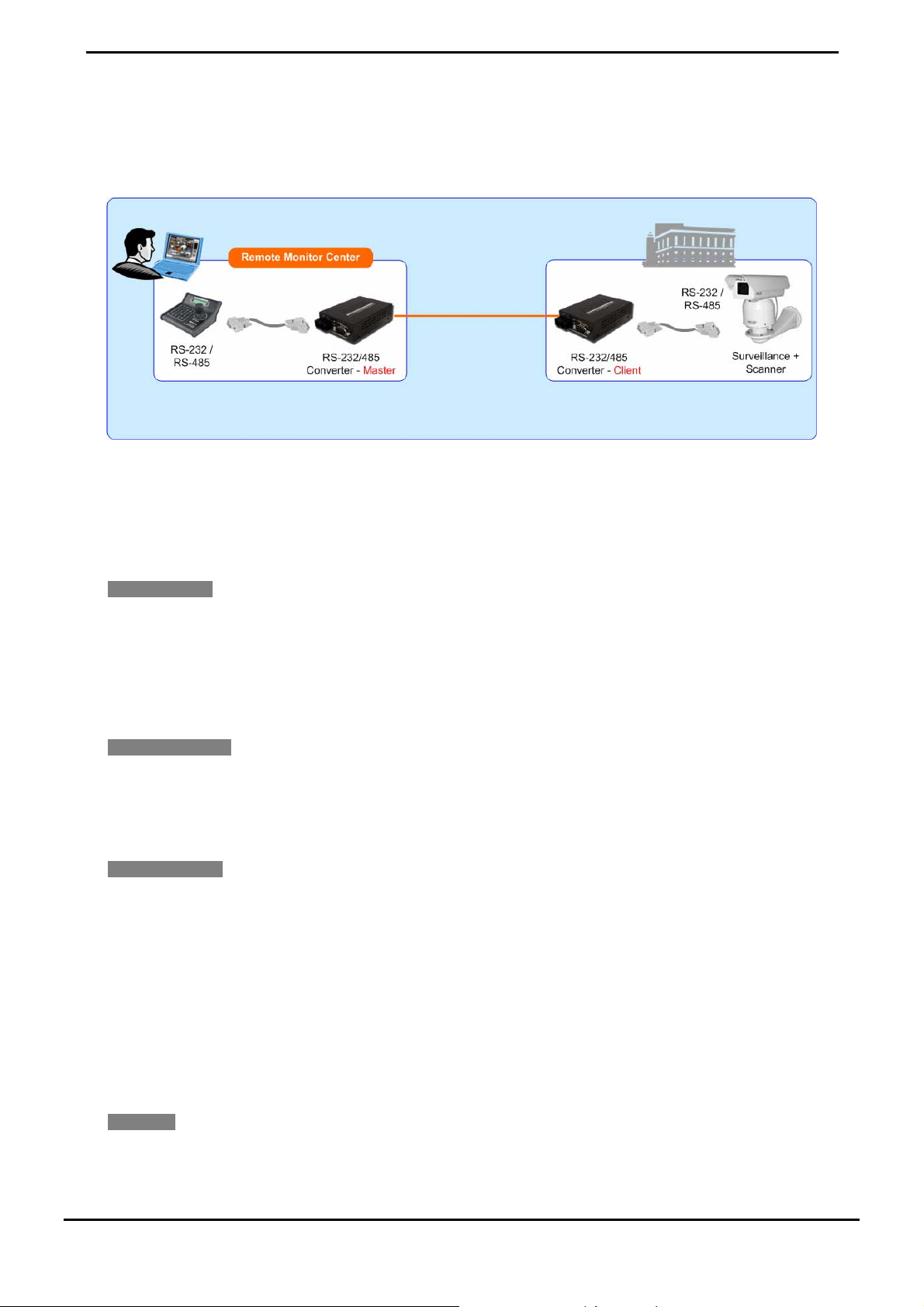
Surveillance motion control – Pair Connection Mode
Using pair connection along with fiber optical patch cord, the ICS-10x extend RS-232/RS-485 interfaces distance from
surveillance and scanner to the control keyboard/joystick which is installed in the remote monitor center.
Figure 1-4 Serial Converter for distance extend application
1.5 Product Features
Serial Interface
One RS-232/422/485 port to one 10/100Base-TX or 100Base-FX Media Converter
Cost effective solution for RS-232 to Ethernet application
Supports RS-232, 4-wire RS-422 or 2/4-wire RS485 operation
Asynchronous serial data rates up to 921600b/s
Ethernet Interface
Complies with IEEE 802.3, IEEE 802.3u 10/100Base-TX, 100Base-FX standard
Supports auto MDI/MDI-X function on RJ-45 Port
Choice of fiber-connector from SC, multi-mode / single-mode fiber
Smart Functions
Standard TCP/IP interface and versatile operation modes
Software Protocol Support ARP, ICMP,TCP/IP, UDP, HTTP server, DHCP client, Telnet server/client
Built-in IP-Base Web interface for remote management
Serial Operation mode selected via Web management
Pair Connection mode for connecting two serial devices over a network
PLANET Smart Discovery utility automatically finds xxx devices on the network
Firmware upgrade via HTTP protocol
Hardware
Compact size for easy Installation:
¾ Standalone - Wall mountable or DIN-Rail mounting (Optional accessory)
-4-
Page 9

¾ Co-work with PLANET MC family Media Chassis ( MC-700/1000R/1500)
LED indicators for easy network diagnose
Reset Button at the front panel for reset to factory default
1.6 PRODUCT SPECIFICAT ION
Products ICS-100 ICS-102 ICS-102S15
Hardware Specification
Interface RS-232 / RS-422 / RS-485
Connector 3-in-1 DB9
Baud rate 110 to 921600bps
Character Bits 5,6,7,8
User’s Manual of ICS-10x
Serial Port
Ethernet Port
Cable Twisted-pair
Protection Built-in 1.5KV magnetic isolation
LED Indicators
Management
Operation Mode
Parity type 1,2
Stop Bit None, Even, Odd
Flow Control None, RTS/CTS, Xon/Xoff
RS-232: TxD, RxD, RTS, CTS, DT R, D SR, D CD, GND
Signals
Standard
Connector RJ-45 SC
Fiber Mode - Multi-Mode Single-Mode
Transmission
Mode
Distance 100m 2km 15km
Optical
Wavelength
RS-422: Tx+, Tx-, Rx+, Rx-, GND RS-485 (2-wire): Data+, DataRS-485 (4-wire): Tx+, Tx-, Rx+, Rx-
IEEE 802.3 10Bas-T
IEEE 802.3u 10/100Base-TX, 100Base-FX
Full-Duplex / Half-Duple Full-Duplex Full-Duplex
- 1300nm 1310nm
50/125μm or
62.5/125μm
multi-mode fiber cable
System: Power
TP or Fiber Port: Link / Active
Serial Port: Link / Active
Web Management
PLANET VCOM Utility
PLANET Smart Discovery Utility
TCP Server
TCP Client
UDP Client
Virtual COM
Telnet Server
Pair Connection – Remote (Slave)
Pair Connection – Local (Master)
9/125μm single-mode
cable
-5-
Page 10

User’s Manual of ICS-10x
Dimension (W x D x H) 97 x 70 x 26mm
Weight 200g
Power Supply External Power Adaptor 5V DC / 2A max.
Power Consumption 5.5 Watts (maximum)
Mechanical Metal
Operating Temperature: 0~50 Degree C
Environment
Emissions FCC Class A, CE Certification Class A
Standards
Regulatory Approval
Compatible Media Converter
Chassis
Note. Reset Button at the rear panel for reset to factory default
Storage Temperat ur e: - 1 0~ 7 0 D egr e e C
Humidity: 10%~90% RH (operating)
5%~90% RH (Storage)
IEEE 802.3 10Base-T
IEEE 802.3u 100Base-TX / 100Base-FX
EIA/TIA RS-232/422/485
RoHS
MC-700 / 1000R / 1500
-6-
Page 11
User’s Manual of ICS-10x
2. INSTALLATION
This section describes the hardware features and installation of the ICS-10X’s components on the desktop or shelf. For
easier management and control of the ICS-10x, familiarize yourself with its display indicators, and ports. Front panel
illustrations in this chapter display the unit LED indicators. Before connecting any network device to the Serial Media
Converter, please read this chapter completely.
2.1 Hardware Description
2.1.1 Product Layout
Figure 2-1 to Figure 2-4 show layout and front panel of ICS-10X.
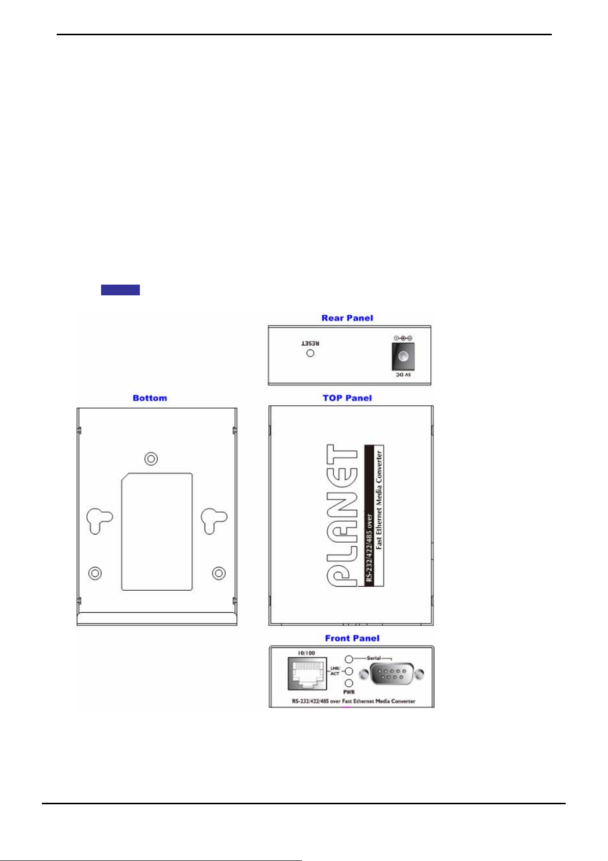
ICS-100 – RS-232 / RS-422 / RS-485 over 10/100Base-TX
Figure 2-1 ICS-100 panel layout
-7-
Page 12
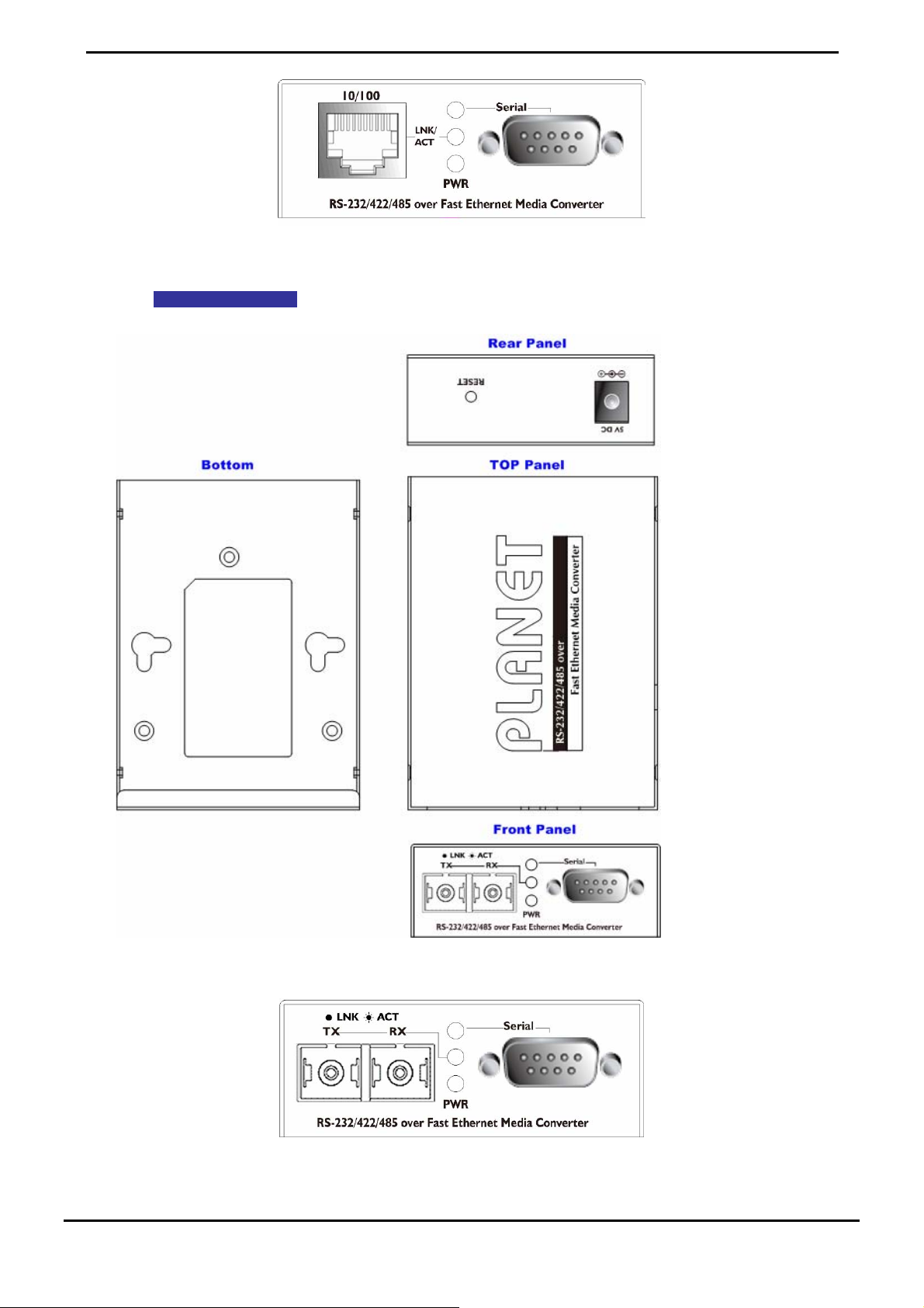
Figure 2-2 PLANET ICS-100 Front Panel
ICS-102 / ICS-102S15 – RS-232 / RS-422 / RS-485 over 10/100Base-FX
User’s Manual of ICS-10x
Figure 2-3 ICS-102 / ICS-102S15 panel layout
Figure 2-4 PLANET ICS-102 Front Panel
-8-
Page 13
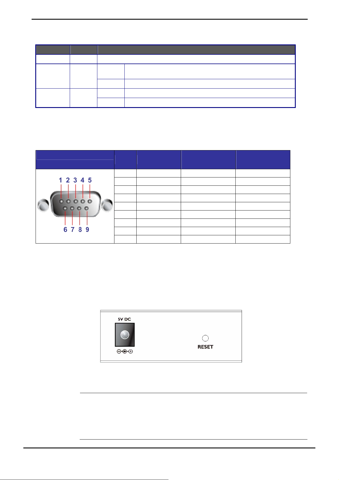
2.1.2 LED Indicators
LED Color Function
PWR Green Lights to indicate that the Converter is powered on.
To indicate that the Fast Ethernet Port is successfully connecting to
the network at 10Mbps or 100Mbps
To indicate the Fast Ethernet Port is receiving or sending data
To indicate that the UART Port is connected successfully
To indicate the UART Port is receiving or sending data
TP or Fiber Green
Serial Green
Lights
Blinks
Lights
Blinks
2.1.3 DB9 Pin Define
DB9 Pin Define for RS-232 / RS-422 / RS-485
User’s Manual of ICS-10x
DB9-PIN RS-232
1 DCD
2 RXD
3 TXD
4 DTR RX- Data B(-)
5 GND
6 DSR TX-
7 RTS RX+ Data A(+)
8 CTS TX+
9 RI
RS-422/485
4-wire
RS-485
2-wire
2.1.4 ICS-10X Rear Panel
The rear panel of the converter indicates one DC jack, which accepts input power with 5V DC 2.5A.
■ ICS-10x series
Figure 2-5 Rear Panel of ICS-10x
1. The device is a power-required device, it means, it will not work till it is powered. If your
networks should active all the time, please consider using UPS (Unin terrupted Pow er Supply )
Power
Notice:
for your device. It will prevent you from network data loss or network downtime.
2. In some area, installing a surge suppression device may also help to protect your Media
Converter from being damaged by unregulated surge or current to the converter or the power
adapter.
-9-
Page 14
User’s Manual of ICS-10x
To press and release the RESET button. The ICS-10X will back to the fa ctory default mode. Be sure that
you backup the current configuration of ICS-10X; else the entire configuration will be erased when
pressing the “RESET” button.
• Press and release the RESET button shortly, the device will be rebooted.
• Press the RESET button more than 10 seconds, the device will back to the factory default
mode; the entire configuration will be erased.
2.2 Install the Converter
This section describes how to install your ICS-10X Web Smart Media Converter and make connections to the converter.
Please read the following topics and perform the procedures in the order being presented. The hardware installation of
PLANET ICS-10X Web Smart Media Converter do n ot need software configuration. To install your ICS-10X on a de sktop
or shelf, simply complete the following steps.
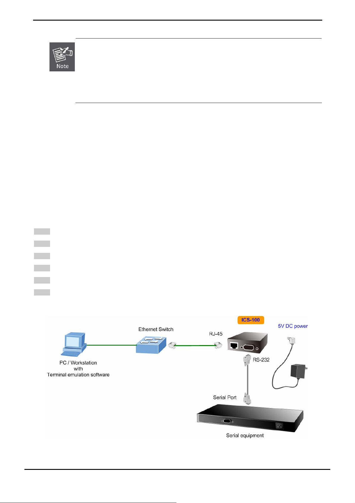
2.2.1 Stand-alone Installation
To install an ICS-10X stand-alone, on a desktop or shelf, simply complete the following steps:
Step 1: Turn off the power of the device/station in a network to which the ICS-10X will be attached.
Step 2: Ensure that there is no activity in the network.
Step 3: Attach RJ-45 / SC Fiber cable from the ICS-10X to the network.
Step 4: Attach RS-232/RS-485 cable from the ICS-10X to the want to connect devices.
Step 5: Connect the 5VDC power adapter to the ICS-10X and verify that the Power LED lights up.
Step 6: Turn on the power of the device/station; the PWR LED (Green) should light when all cables are attached.
Figure 2-6 ICS-100 stand alone installation
-10-
Page 15
User’s Manual of ICS-10x
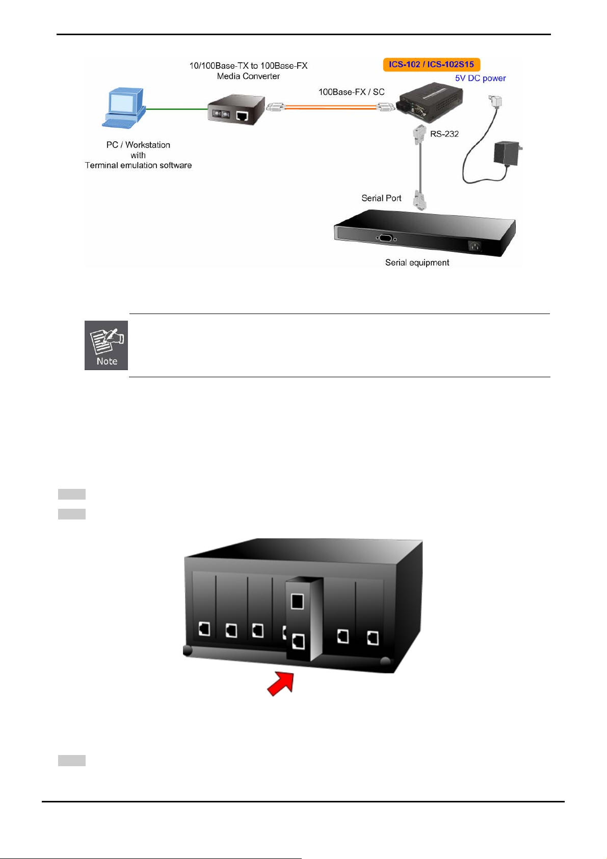
Figure 2-7 ICS-102 / ICS-102S15 stand alone installation
Please refers to APPENDIX-A for detailed wiring information of the ICS-10X.
To prevent from optic acceptor malfunction, check the both wires / transmitter before power on the
converter.
2.2.2 Chassis Installation and Rack Mounting
To install the Media Converter in a 10-inch or 19-inch with standard rack, follow the instructions described below.
Step 1: Place your ICS-10X on a hard flat surface, with the front panel positioned towards your front side.
Step 2: Carefully slide in the module until it is fully and firmly fitted into the slot of the chassis.
Figure 2-8 Insert a Media Converter into an availabl e sl ot
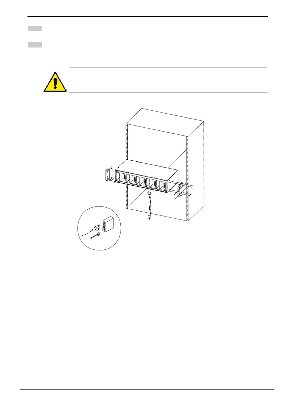
Step 3: Attach a rack-mount bracket to each side of the Chassis with supplied screws attached to the package.
-11-
Page 16
User’s Manual of ICS-10x
Step 4: After the brackets are attached to the chassis, use suitable screws to securely attach the brackets to the rack, as
shown in Figure 2-2.
Step 5: Precede with the steps 4 and steps 5 of session 2.2.1 Stand-alone Inst al lation to connect the network cabling
and supply power to your converter.
You must use the screws supplie d with the mounting brackets. Damage caused to the parts by using
incorrect screws would invalidate your warranty.
Figure 2-9 Mounting the Chassis in a Rack
-12-
Page 17

User’s Manual of ICS-10x
3. MANAGEMENT
This chapter describes how to manage the ICS-10X. Topics include:
- Overview
- Management methods
- Assigning an IP address to the ICS-10X
- Logging on to the ICS-10X
3.1 Overview
This chapter gives an overview of converter management. The ICS-10X provides a simply WEB browser interface.
Using this interface, you can perform various converter configuration and management activities, including:
System
Network Configuration
Operation Mode
Serial Port Configuration
Please refer to the following Chapter 4 for more details.
3.2 Requirements
■ Network cables.
For ICS-100: Use standard network (UTP) cables with RJ45 connectors.
For ICS-102 / ICS-102S15: Use Multi-mode or Single Mode fiber patch cord with SC connectors.
■ Subscriber PC installed with Ethernet NIC (Network Card)
■ Workstations of subscribers running Windows 98/ME, NT4.0, 2000/2003/XP, MAC OS X or later, Linux, UNIX or
other platform compatible with TCP/IP protocols.
■ Above PC installed with WEB Browser, such as Microsoft Internet Explore or Mozilla Firefox
It is recommended to use Internet Explore 6.0 or above to access Serial Media
Converter.
-13-
Page 18
User’s Manual of ICS-10x
3.3 Management Methods
The way to manage the ICS-10X:
- Web Management via a network or dial-up connection
3.3.1 Web Management
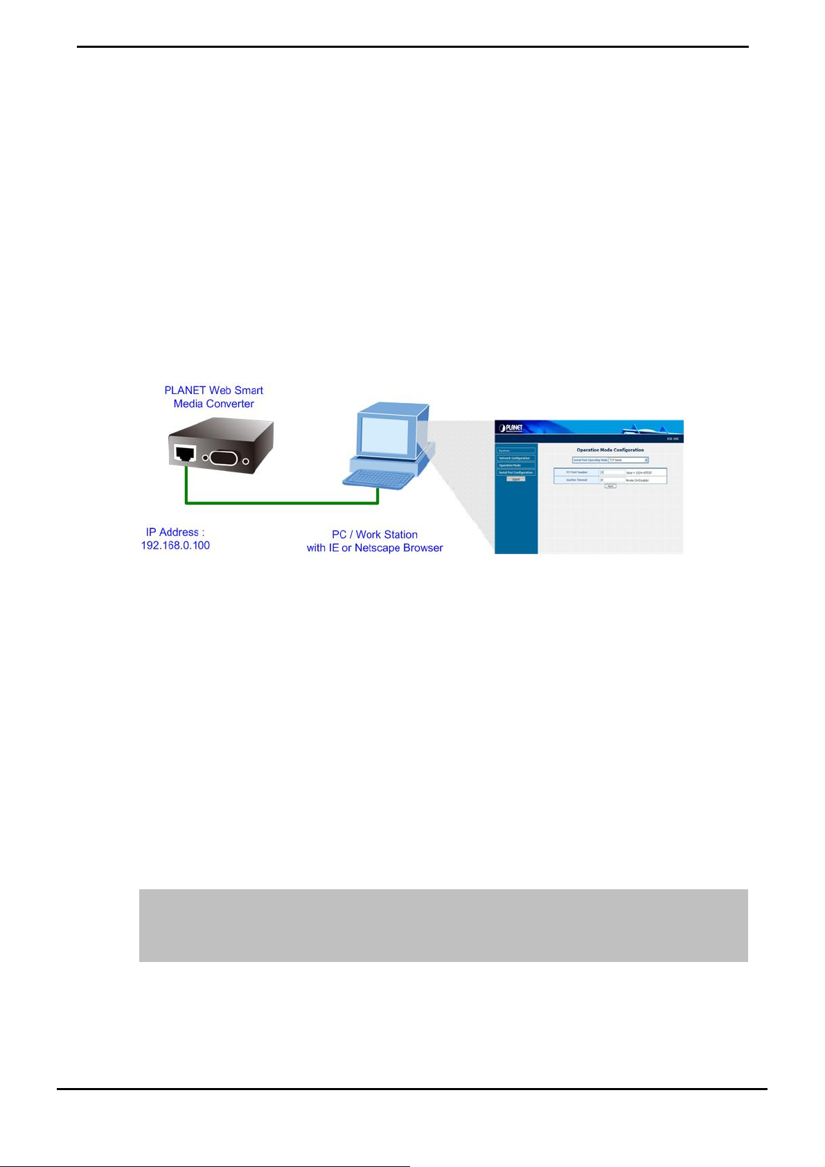
The PLANET Web-Smart Media Converter provides a built-in browser interface. You can manage the ICS-10X remotely
by having a remote host with web browser, such as Microsoft Internet Explorer, Netscape Navigator or Mozilla Firefox.
Using this management method:
The ICS-10X must have an Internet Protocol (IP) address accessible for the remote host.
Figure 3-1 Web Management over Ethernet
3.3.2 Login the Media converter
Before you start configure the ICS-10X, please note the ICS-10X is con figured through an Ethe rnet connection, make su re
the manager PC must be set on same the IP subnet address.
For example, the default IP address of the ICS-10X is 192.168.0.100, then the manager PC should be set at 192.168.0.x
(where x is a number between 2 and 254), and the default subnet mask is 255.255.255.0.
1. Use Internet Explor er 6.0 or above Web browser. Enter IP add ress http://192.168.0.100 (the factory-default IP
address) to access the Web interface.
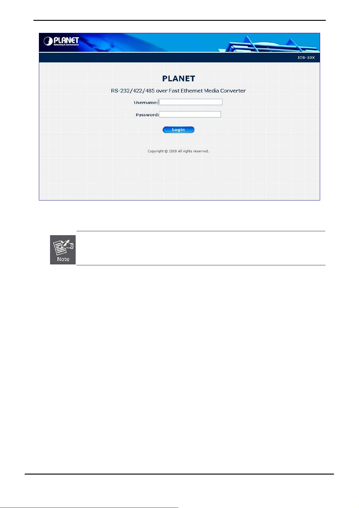
2. When the following login screen appears, plea se en ter the de fault u sername and pa ssword (defaul t use r name and
password is "admin"). Press Login to enter the main screen of ICS-10X. The login screen in Figure 3-1 appears.
Default IP Address: 192.168.0.100
Default Account: admin
Default Password: admin
-14-
Page 19
User’s Manual of ICS-10x
Figure 3-2 Login screen
1. For security reason, please change and memorize the new password after this first setup.
2. Only accept command in lowercase letter under web interface.
-15-
Page 20

User’s Manual of ICS-10x
4. WEB CONFIGURATION
The ICS-10X Web Smart Media Converter provide Web interface for Converter smart function configuration and make the
Converter operate more effectively - They can be configured through the Web Browser. A network administrator can
manage and monitor the ICS-10x from the local LAN. This section indicates how to configure the Media Converter to
enable its smart function.
4.1 Main Menu
After a successful login, the main screen appears, the main screen displays the converter Welcome page. The screen in
Figure 4-1 appears.
Figure 4-1 Web Main screen
As listed at the left of the main scr e e n, the c o nf ig ur ab l e smar t f un ct i ons a r e s ho wn as b el o w:
System –
Network Configuration-
Operation Mode –
Serial Port Configuration-
Check the hardware,software version and System MAC address and IP address
of the converter. And the password changed firmware upgrade / Factory default /
system reboot.
Setup the IP address of the converter.
Setup the serial port mode: “TCP server”, “TCP client”, “UDP client”, “Virtual
COM”, “Telnet Server”, “Pair Connection – Remote (Master)” and “Pair
Connection – Remote (Slave)”.
Setup the serial por t v al u e
-16-
Page 21

User’s Manual of ICS-10x
4.2 System
4.2.1 System Information
The System Information page provides information for the current device. System Info page helps a network manager to
identify the versions and IP Address etc. The screen in Figure 4-2 appears.
The page includes the following fields:
• Model Name
• Software Version
• MAC Address
• IP Address
• Subnet Mask
• Gateway
• System Name
• Current Operation
Mode
Figure 4-2 System Information screen
Specifies the device Model Name.
The current software version running on the device.
Specifies the device MAC address.
The current IP Address of the device. The IP Addre ss could be manual assigned.
The factory default value is 192.168.0.100.
The current IP Subnet Mask setting on the device. The factory default value is
255.255.255.0.
The default gateway for the IP interface. The factory default value is
192.168.0.254.
The current IP Subnet Mask setting on the device.
Show the current serial port operation mode.
-17-
Page 22

4.2.2 Password Setting
This function provides administrator to secure Web login. The screen in Figure 4-3 appears.
User’s Manual of ICS-10x
Figure 4-3 Password Setting screen
The page includes the following configurable data:
Login Name
New Password
Confirm Password
After change the default password, if you forget the password. Please press and release the “Reset”
button in the front panel of ICS-10X, the current setting will be lost and the ICS-10X will restore to the
default mode.
Displays the user name.
Specifies the new password. The password is not displayed. As it entered an “y”
corresponding to each character is displayed in the field.
(The maximum length is 15 characters)
This confirms the new password. The password entered into this field must be
exactly the same as the password entered in the Password field.
-18-
Page 23

User’s Manual of ICS-10x
4.2.3 Firmware upgrade
The Firmware Upg r ad e page contains fields for downloading system image files from the Local File browser to the
device. The screen in Figure 4-4 appears.
Figure 4-4 Firmware Upgrade screen
To open Firmware Upgrade screen perform the folling:
2. Click System -> Firmware Upgrade then click Load.
3. The Firmware Upgrade screen is displayed as in Figure 4-5.
Figure 4-5 Firmware Upgrade screen
-19-
Page 24

4. Then the “Firmware Upgrade Mode” displayed as in Figure 4-6.
Figure 4-6 Firmware Upgrade screen
User’s Manual of ICS-10x
Click the “Browse” button of the main page, the system would pop up the file selection menu to choose firmware.
Figure 4-7 Windows file selection menu popup
5. Select on the firmware then click “Upgrade”. The firmware upgrade may take 60 seconds.
Do not power off the converter until the update progress is complete.
Do not quit the Firmware Upgrade page w ithout pre ss the “Upgrade” button - afte r the image i s
loaded. Or the system won’t apply the new firmware. Users have to repeat the firmware
upgrade processes again.
-20-
Page 25

User’s Manual of ICS-10x
4.2.4 Factory Default
The Factory Defaul t can re set the ICS-10x back to the factory de fault mode. Be aware tha t the entire configuration will be
reset, and the IP address of the ICS-10x will be set to “192.168.0.100”. The screen in Figure 4-8 appears.
Figure 4-8 Factory Default progress screen
4.2.5 System Reboot
The System Reboot can restart the ICS-10x. The screen in Figure 4-9 appears.
Figure 4-9 System Reboot progress screen
-21-
Page 26

User’s Manual of ICS-10x
4.3 Network Configuration
This function allows setting the value for network configuration. The value is DHCP client, IP address, Subnet Mask,
Gateway, DNS and system name. Press the “Apply” button to set the value. The screen in Figure 4-10 appears.
Figure 4-10 Network Configuration screen
The page includes the following configurable data:
• DHCP Client
• IP Address
• Subnet Mask
• Gateway
Disable or enable the DHCP function.
When DHCP Client is set to “Enable”, the ICS-10x will send a DHCP request to the
DHCP server in the network. Once the DHCP Server get the request, it will assign a
dynamic IP address, netmask and gateway to the ICS-10x.
The factory default setting is “Disable”
Assign the converter IP Address.
The factory default value is 192.168.0.100
Assign the converter Subnet Mask.
The factory default value is 255.255.255.0
Assign the converter gateway.
The factory default value is 192.168.0.254
• DNS
• System Name
DNS is the way that Internet domain names are identified and translated into IP
addresses. A domain name is an alphanumeric name, such as planet.com, that it is
usually easier to remember. Assign the DNS server IP address.
Allow set value for system name. (The maximum length is 15 characters).
-22-
Page 27

User’s Manual of ICS-10x
When DHCP Client is set to Enable, the IP Address, Subnet Mask, Gateway and DNS fields are not
allow to be changed.
If the Media Converter is set to DHCP Client enable, you can use PLANET Smart Discovery or
PLANET VCOM Utility to search the Media Converter which with DHCP assigned IP address.
4.4 Operation Mode
The ICS-10x make connected Serial equipmen t becomes IP-based. That also makes them be able to connect to a TCP/IP
networking immediately. The ICS-10x allow traditional Computer/Client COM ports access to a serial equipment
anywhere on the Ethernet LAN network.
This Operation Mode configure page allows setup Serial interface operation mode as below:
TCP Server
TCP Client
UDP Client
Virtual COM
Telnet Server
Pair connection (local)
Pair connection (Master)
Figure 4-11 Operation Mode C o nf i g ur at i o n s cr e e n
Select the operation mode for the application and press the “Apply” button to take affect.
4.4.1 TCP server mode
When the ICS-10x be configured to TCP Server mode, it allows Serial device that connected to serial port of ICS-10x to
establish TCP communication over Intranet or Internet network between:
Remote Host (Computer) with Serial applications using TCP/IP network socket programs
-23-
Page 28

User’s Manual of ICS-10x
Other ICS-10x with TCP Client mode
It opens the TCP port of ICS-10x to wait for serial application to establish a TCP connection. After the connection is
established, data can be transmitted in both directions.
The parameter defines the maintenance status for listen for the TCP connection.
Figure 4-12 TCP Server mode
The screen in Figure 4-13 appears. When the changed operation mode, the user should be changed the Serial Port
Configuration.
Figure 4-13 TCP Server Configuration screen
The page includes the following fields:
• Seri al Po rt Op er ati on
Mode
Choose different mode:
TCP Server
TCP Client
UDP Client
Virtual COM
Telnet Server
Pair connection (local)
Pair connection (Master)
• TCP Port Number
The default mode is “TCP Server”.
The TCP port that ICS-10X uses to listen to connections and that other device
must use to contact ICS-10X. To avoid conflicts with well known TCP ports, the
default is set to “1024”.
-24-
Page 29

User’s Manual of ICS-10x
• Inacti ve Timeout
Use the parameter to set an inactive timeout. The unit drops the connection if
there is no activity on the serial line before the set time expires. To disable the
inactive timeout enter “0”.
Example: Use Microsoft Windows Hyper Terminal, TCP/IP Winsock mode
HyperTerminal is a program that you can use to connect to other computers, Telnet sites, online services, and host
computers, using either your modem, a null modem cable, a Console cable or Ethernet connection.
The users want to use the TCP Server mode to connect to a Ethernet Switch via Hyper Terminal, Winsock mode
1. Setup Operation Mode and Serial Port of ICS-10x
2. Hyper Terminal set up a new connection with the TCP/IP Winso ck
Setup Operation Mode and Serial Port of ICS-10x
1. From the WEB interface, set the Serial operation mode of ICS-10x to “TCP Server” and set the TCP Port Number to
“23”.
Figure 4-14 Example: TCP Server Configuration sc reen
2. Set the Serial Port Configur at io n of IC S- 10 x as bel o w:
Mode:
Baudrare:
Character Bits:
Parity Type :
Stop Bit :
Hardware Flow Control:
RS-232
9600
8
none
1
none
-25-
Page 30
User’s Manual of ICS-10x
Figure 4-15 Example: Serial Port Configuration screen
Hyper Terminal setup a new connection with TCP/IP Winsock
3. Open HyperTerminal
Figure 4-16 Example Hyper Terminal screen
-26-
Page 31

4. On the File menu, click New Connection.
5. In the Name box, type a name that describes the connection.
6. In the Icon box, click the appropriate icon, and then click OK.
User’s Manual of ICS-10x
Figure 4-17 Example: Hyper Terminal – Create new connection
7. In the Connect To dialog box, choose which port or modem you want to use in the Connect using drop-down box.
Figure 4-18 Example: Hyper Terminal – Connect type
8. In this case we are connecting via TCP/IP (Winsock), enter the host address and port number, and then click OK.
9. If the Port Settings dialog box is displayed, complete the information, and click OK.
-27-
Page 32

User’s Manual of ICS-10x
Figure 4-19 Example: Hyper Terminal configuration
Value Description
Host address The address or name of the connection you want to crea te. Thi s can be in standard In ternet
dotted notation (for example, w.x.y.z) or can be the site's user-friendly name.
port The number of the port that you want the connection to use. Port 23 is the default.
10. Then can use the console like connect the serial cable with the switch.
Figure 4-20 TCP/IP Winsock connection screen
-28-
Page 33

User’s Manual of ICS-10x
4.4.2 TCP Client mode
When the ICS-10x be configured to TCP Client mode, it allows Serial device that connected to serial port of ICS-10x to
establish TCP communication actively over Intranet or Internet network between:
Remote Host (Computer) with Serial applications using TCP/IP network socket programs
Other ICS-10x with TCP Server mode
After the data has been transferred , the ICS-10x can disconnect automatically from the Remote Host depends on the TCP
Inactive timeout settings. The parameter defines the maintenance status for listen for the TCP connection
.
Figure 4-21 TCP Client Mode
The screen in Figure 4-22 appears. When the changed operation mode, the user should be changed the Serial Port
Configuration.
The page includes the following fields:
Figure 4-22 TCP Client Configuration screen
• Remote Host IP
Address
• Remot e Ho st Port
Number
• Inacti ve Timeout
Allow the ICS-10X to connect actively to the remote host who se IP address is set
by this parameter.
The remote host port number that ICS-10X uses to listen to connections and that
other device must use to contact ICS-10X. To avoid conflicts with well known
TCP ports, the default is set to “1024”.
Use the parameter to set an inactive timeout. The unit drops the connection if
there is no activity on the serial line before the set time expires. To disable the
inactive timeout enter “0”.
-29-
Page 34

User’s Manual of ICS-10x
4.4.3 UDP Client mode
When the ICS-10x be configured to UDP Client mode, it allows Serial device that connected to serial port of ICS-10x to
quickly transmit data to multiple Remote Hosts over Intranet or Internet network by unicast or multicast. It also makes the
Serial device to receive data from more than one Remote Hosts.
The parameter defines the main tenance sta tus for listen fo r the UDP connection
the remote IP Address and Local listen port number.
Figure 4-23 UDP Client Mode
. In UDP Client mode, you need to define
The screen in Figure 4-24 appears. When the changed operation mode, the user should be changed the Serial Port
Configuration.
Figure 4-24 UDP Client Configuration screen
-30-
Page 35

The page includes the following fields:
User’s Manual of ICS-10x
• Local UDP Po rt
• Remote Address
• Remote Port
Enter the local port number
Enter the IP address of the remote device.
Enter the remote port number of the remote device.
4.4.4 Virtual COM mode
When the ICS-10x be configured to Virtual COM mode, it allows Serial device that connected to se rial port of ICS-10x to
establish TCP communication over Intranet or Internet netwo rk between Re mote Host (Computer). The Virtual COM Po rt
driver has to be installed at the Remote Ho st. Users can send data by Vi rtual COM port, and Virtual COM port will transfer
data to Ethernet by windows socket. The Virtual COM driver maps IP Address / Port of ICS-10x to a local COM port on the
Remote Host (Computer). Once the Virtual COM connection is established, the applications work as the serial device is
direct connected to the Remote Ho st’s rea l COM port. Afte r the connection is e stablished, data can be tran smitted in bo th
directions.
With connect to ICS-10x Serial over Fast Ethernet Converter, the serial devices are not limited to physical connection to
the PC/Remote Host COM port and able to be extension over longer distance. The parameter defines the maintenance
status for the Virtual COM
.
Figure 4-25 Virtual COM Mode
When the changed operation mode, the use r should be changed the Serial Port Configuration. The screen in Figure 4-14
appears.
Figure 4-26 Virtual COM Configuration screen
-31-
Page 36

The page includes the following fields:
User’s Manual of ICS-10x
• TCP Port Number
• Inacti ve Timeout
The TCP port that ICS-10X uses to listen to connections and that other device
must use to contact ICS-10X. To avoid conflicts with well known TCP ports, the
default is set to “1024”.
Use the parameter to set an inactive timeout. The unit drops the connection if
there is no activity on the serial line before the set time expires. To disable the
inactive timeout enter “0”.
Example: Use PLANET VCOM Utility + Microsoft Windows Hyper terminal COM
Port mode
Figure 4-27 Example Virtual COM Mode
The user want to use the virtual COM like to use the serial cable connect the switch.
1. Setup Operation Mode and Serial Port of ICS-10x
2. Use PLANET VCOM Utility to create virtual COM Port
3. Hyper Terminal set up a new connection with the virtual COM port
Setup Operation Mode and Serial Port of ICS-10x
1. From the WEB interface, set the Serial operation mode of ICS-10x to “Virtual COM” and set the TCP Port Number
to “23”.
-32-
Page 37

Figure 4-28 Example: Virtual COM Conf i g uration screen
2. Set the Serial Port Configur at io n of IC S- 10 x as bel o w:
User’s Manual of ICS-10x
Mode:
Baudrare:
Character Bits:
Parity Type :
Stop Bit :
Hardware Flow Control:
RS-232
9600
8
none
1
none
Figure 4-29 Example: Serial Port Configuration screen
-33-
Page 38

User’s Manual of ICS-10x
VCOM Utility to create virtual COM port
3. This mode will run with the softw are-“PLANET VCOM Utility”. Open the VCOM utility , click “Search Device” to point
out the ICS-10x that want to be configured.
Figure 4-30 Example: Virtual COM Conf i g uration screen
4. Choose the VCOM tab and create COM 9 like below:
Figure 4-31 Example: Virtual COM Conf i g uration screen
-34-
Page 39

Hyper Terminal setup a new connection with virtual COM port
5. On the File menu, click New Connection.
6. In the Name box, type a name that describes the connection.
7. In the Icon box, click the appropriate icon, and then click OK.
User’s Manual of ICS-10x
Figure 4-32 Example: HyperTerminal Configuration screen
8. In the Connect to dialog box, choose which port you want to use in the Connect using drop-down box. In this case,
choose COM9 (as created in Step-4)
Figure 4-33 Example: HyperTerminal Configuration screen
9. Set the parameter like below, click “Apply” to take effect.
-35-
Page 40

User’s Manual of ICS-10x
Figure 4-34 Example: HyperTerminal Com port properties screen
10. After the Virtual COM connection is established, open the VCOM utility again to check the COM9 information.
Figure 4-35 Example: VCOM Utility, COM9 information
11. Then can use the console like connect the serial cable with the switch.
-36-
Page 41

User’s Manual of ICS-10x
Figure 4-36 Example: Hyper Terminal COM port screen
4.4.5 Telnet Server mode
TELNET (TELecommunication NETwork) is a network protocol used on the Internet or local area network (LAN)
connections. The Telnet protocol type is the correct setting for most servers and serial devices, such as Managed Ethernet
switches or Gateways. In most of the case, the telnet use TCP port 23 as communication port.
The parameter defines the maintenance status for Telnet server
.
Figure 4-37 Com port screen
When the changed operation mode, the use r should be changed the Serial Port Configuration. The screen in Figure 4-38
appears.
-37-
Page 42

Figure 4-38 Telnet Server Configur at i o n scre e n
The page includes the following fields:
User’s Manual of ICS-10x
• TCP Port Number
• Inacti ve Timeout
The ICS-10X’s “telnet server mode”--if the user used the MS-DOS telnet command it will
show double character. So the user can use other Telne t software like: “putty ” or “NetTerm”.
The TCP port that ICS-10X uses to listen to connections and that other device
must use to contact ICS-10X. To avoid conflicts with well known TCP ports, the
default is set to “1024”.
Use the parameter to set an inactive timeout. The unit drops the connection if
there is no activity on the serial line before the set time expires. To disable the
inactive timeout enter “0”.
Example 1: Telnet Command in Windows Platform
Figure 4-39 Example Telnet Server
-38-
Page 43

Setup Operation Mode and Serial Port of ICS-10x
1. Set the ICS-10X mode to “Telnet server mode” from web interface.
2. Set the Serial Port Conf ig ur at i o n of ICS- 1 0x as b el o w:
User’s Manual of ICS-10x
Mode:
Baudrare:
Character Bits:
Parity Type :
Stop Bit :
Hardware Flow Control:
RS-232
9600
8
none
1
none
Execute “Telnet” command from Windows Start Menu
3. Click the Start Menu and go to Run
4. Type "telnet" without the quotes, and hit enter.
Figure 4-40 Example Windows Excuse - Telnet
5. While the Telnet window appears, type “open xxx,xxx,xxx,xxx”, xxx is the IP address of the ICS-10x Telnet Server.
In this case we type “open 192.168.0.100” and press enter.
Figure 4-41 Example Windows Excuse - Telnet
6. Then can use the telnet connection to configure the switch just like console direct connect to the COM port of the
switch.
-39-
Page 44

Figure 4-42 Example Windows Excuse - Telnet
7. To quit the Telnet session, press “CTRL+]” and then type “quit”
User’s Manual of ICS-10x
Figure 4-43 Example Windows Excuse - Telnet
Example 2: Putty software in Windows Platform
PuTTY is a free implementation of Telnet and SSH for Win32 and Unix platforms, along with an xterm terminal emulator.
In this case we use Putty to telnet to the ICS-10x-Telnet Server mode for remote console login.
1. Set the ICS-10X mode to “Telnet server mode” from web interface.
2. Run the Telnet software like “Putty” and set the parameter like below:
-40-
Page 45

User’s Manual of ICS-10x
Figure 4-44 Putty Configurat io n sc r e en
8. Then can telnet IP address like to telnet switch’s IP.
Figure 4-45 Putty telnet screen
-41-
Page 46

User’s Manual of ICS-10x
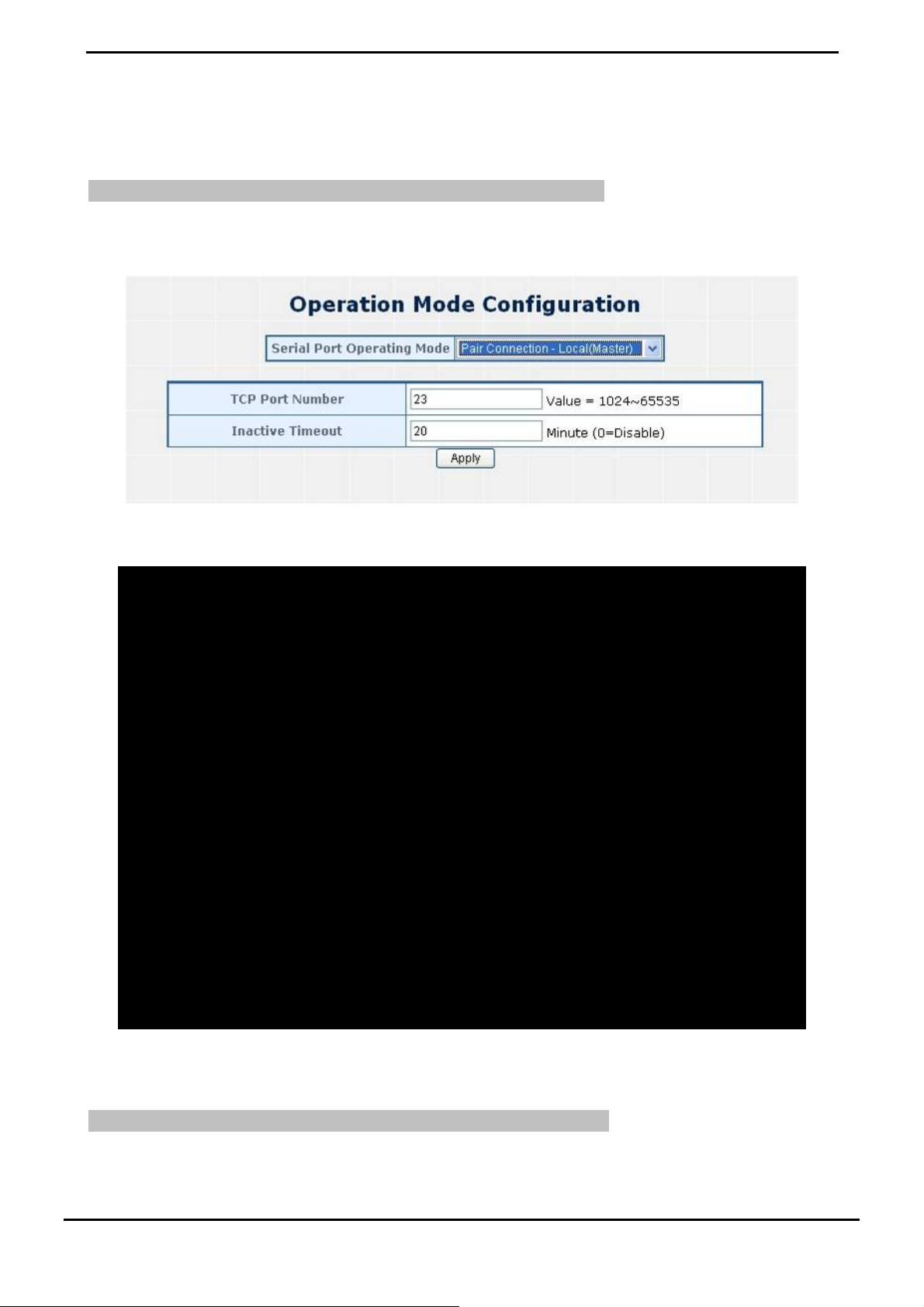
4.4.6 Pair Connection– Local mode
The parameter defines the maintenan ce sta tu s for listen for the pair connection. To ma ke a long d istance communica tion
between two serial equipment, configure two ICS-10x w ith Pair Connecti on mode and setup on e as a Maste r (Local side)
and the other as a Slave (Remote side).
Pair Connection – Local (Master) – the ICS-10x is locate close to t he H os t C om put e r or co nt r ol d ev ice and
connect to it via serial interface.
Pair Connection – Remote (Slave) – the ICS-10x is locate close to the remote serial equipment and conne ct to
it via serial inte rface..
Figure 4-46 Pair Connection mode
In effect, this converter will be acting as a TCP server. The screen in Figure 4-46 appears. When the changed operation
mode, the user should be changed the Serial Port Configuration.
Figure 4-47 Pair Connection – Local (Master) Configuration screen
• TCP Port Number
• Inacti ve Timeout
The TCP port that ICS-10X uses to listen to connections and that other device
must use to contact ICS-10X. To avoid conflicts with well known TCP ports, the
default is set to “1024”.
Use the parameter to set an inactive timeout. The unit drops the connection if
there is no activity on the serial line before the set time expires. To disable the
inactive timeout enter “0”.
-42-
Page 47

User’s Manual of ICS-10x
4.4.7 Pair Connection – Remote mode
The parameter defines the maintenance status for li sten for the pair connection. In effe ct, thi s converte r wi ll be acting a s a
TCP client. The screen in Figure 4-48 appears.
When the changed operation mode, the user should be changed the Serial Port Configuration.
Figure 4-48 Pair Connection – Remote (Slave) Configuration screen
• TCP Port Number
• Inacti ve Timeout
Important!
While using Pair Connection mode for two RS-232 services distance extend, the DB9/RS-232 cables
are very importance in this application. There are much kind of RS-232 cables, such as straight cable
(standard) and Null-Modem cable. Please make sure the DB9/RS-232 cables match the below
constriction:
Serial Device to ICS-10x/Remote (Slave) – Use the original RS-232 serial cable attached inthe
serial device package.
Host / Client to ICS-10x/Local (Master) – It has to use the Null-Modem cable!
Users can use the Null-Modem cable directly connect to the ICS-10x (Master), or use the Null-Modem
DB9 connector, as the picture shows:
The TCP port that ICS-10X uses to listen to connections and that other device
must use to contact ICS-10X. To avoid conflicts with well known TCP ports, the
default is set to “1024”.
Use the parameter to set an inactive timeout. The unit drops the connection if
there is no activity on the serial line before the set time expires. To disable the
inactive timeout enter “0”.
Once the Pair Connection mode of two ICS-10x be correctly configured but still fail link, check the
RS-232 cables!
-43-
Page 48

User’s Manual of ICS-10x
Example: Two ICS-10x with Pair Connection mode
One be configured as Pair Connection – Local (Master)
The other one be configured as Pair Connection – Remote (Slave)
Via the RS-485 interface, the external scanners, speed dome cameras and PTZ receivers can be controlled by the
keyboard which provides upward, downward, leftward, rightw ard, clockwise and counterclockw ise with the joysti ck. In this
case, we use two ICS-10x to extend the distance between an IP surveillance PT Camera and a Control keyboard. Bo th of
the two equipments are implemented with RS-485 interface.
The two of the ICS-10x master and slave with below settings:
ICS-10x Master
Connect to Control Keyboard
IP Address / Subnet Mask 192.168.0.100 / 255.255.255.0
Operation Mode
Serial Port Configuration
ICS-10x Slave
Connect to Speed Dome Camera, PTZ or Scanner
IP Address / Subnet Mask 192.168.0.101 / 255.255.255.0
Operation Mode
Serial Port Configuration
Topology:
Mode: Pair Connection – Local
TCP Port Number : 1024
Serial Mode: RS-485
Baudrare: 9600
Character Bits: 8
Parity Type : none
Stop Bit : 1
Hardware Flow Control: none
Mode: Pair Connection – Remote
Remote Host IP Address : 192.168.0.100
Remote Host Port Number : 1024
Serial Mode: RS-485
Baudrare: 9600
Character Bits: 8
Parity Type : none
Stop Bit : 1
Hardware Flow Control: none
Figure 4-49 Two ICS-10x configured with Pair-Connection
-44-
Page 49
User’s Manual of ICS-10x
1. Connect the converter with the IP camera for RS-485 interface like PLANET product: “ICA-651”.
2. Connect the converter with the control keyboard for RS-485 interface like PLANET product: “CAM-KB300”.
ICS-10x – Master: be configured as Pair-Connecti o n- Lo cal
3. From Web interface, login the ICS-10x with IP address = 192.168.0.100, set up the operation mode of this unit to be
“ Pair Connection-Local (master)”
Figure 4-50 Pair Connection – Local, operation mode configuration
4. Set the Serial Port mode of ICS-10x-Master to RS-485.
Figure 4-51 Pair Connection – Local, serial port configuration
ICS-10x – Slave: be configured to Pair-Connection-Remote
5. From Web interface, login the ICS-10x with IP address = 192.168.0.101, set up the operation mode of this unit to be
“ Pair Connection-Local (master)”
-45-
Page 50

Figure 4-52 Pair Connection –Remote, operation mode configuration
6. Set the Serial Port mode of ICS-10x-Slave to RS-485.
User’s Manual of ICS-10x
Figure 4-51 Pair Connection – Local, serial port configuration
7. Then the control keyboard cans remote control the IP camera.
-46-
Page 51

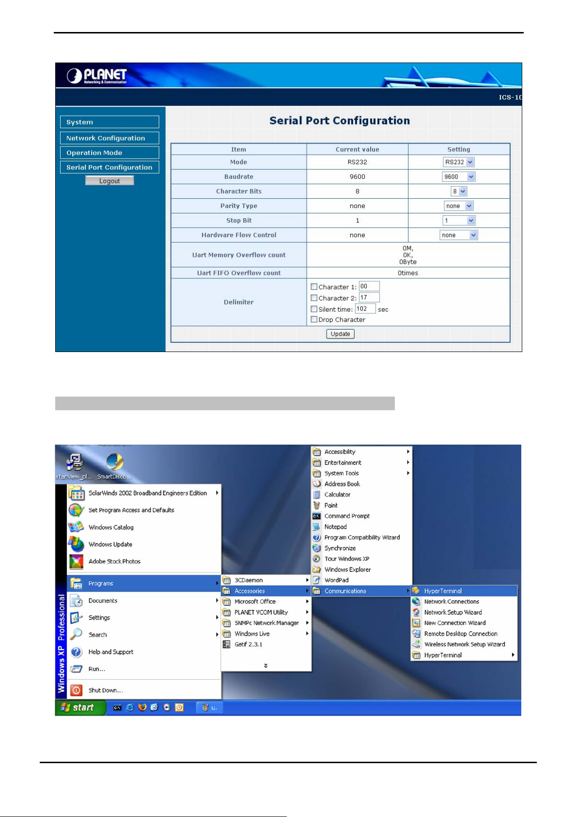
4.5 Serial Port Configuration
The page shows the converter’s serial Port configuration. The screen in Figure 4-52 appears.
User’s Manual of ICS-10x
The page includes the following fields:
• Mode
• Baudrate
• Character Bits
• Parity type
• Stop Bit
• Hardware Flow Control
Figure 4-52 Converter Status page screen
From the drop-down menu, select the serial port mode:
RS232
RS-422
RS-485
The unit and attached serial device, such as a modem, must agree on a speed o r
baud rate to use for the serial connection, Valid baud rates.
It’s in the range of 110bps to 921600bps.
Indicates the number of the bits in a transmitted data package. The al lowed value
is 5,6,7,8
The default is “8”.
Checks for the parity type. The default value is “none”.
The stop bit follows the data and parity bits in serial communication. It indicates
the end of transmission. The default is “1”.
Flow control manages data flow between devices in a network to ensure it is
processed efficiently. Too much data arriving before a device is prepared to
manage it causes lost or retransmitted data.
• Delimiter
XON/XOFF, RTS/CTS, DTR/DSR
The default value is “none”.
Character The Character 1 and Character 2 allow the use to enter two ASCII
character (in hex format) that delimit the be ginning and end of a message . When
a message with both ther e d el im it e rs i s rec e iv ed at th e s eri al p or t, th e dat a
-47-
Page 52

User’s Manual of ICS-10x
contained in the serial buffer is paced in an Ethernet packet and sent out the
Ethernet port.
Silent Time: For the defined period of time passed, the serial port stops data
transmission and close the connection to remote host.
Drop Character: If the incoming data contain character 1 or character 2, the
packet will be dropped
The default value is “Disable”
■ Logout
Press this function; the web interface will go back to login screen. The screens in Figure 4-53 and Figure 4-54 appear.
Figure 4-53 Logout dialogues screen
Figure 4-54 Login screen
-48-
Page 53

User’s Manual of ICS-10x
5. SOFTWARE VCOM UTILITY
The ICS-10X Web Smart Media Converter provides software for Converter smart function configuration when the
Converter operation mode on “Virtual COM”. - They can be configured through the Console. Two function groups are
provide to easy used, can search device and create virtual COM to view as the console port.
This program can search ICS-10x Series devices, it will show information of the device. And user can use VCOM function
creates virtual com port for user using. Users can send data by virtual com port, and virtual com port will transfer data to
Ethernet by windows socket. While VCOM got data from Ethernet, it will transfer data to virtual com port by virtual com
component.
The VCOM is an integrated software suite that bundles Device Server Administrator and IP Serial Library, and provides
something you need to monitor your ICS-10X from a remote location.
5.1 Installing the VCOM Utility
1. Once the Setup program starts running, click Next when the Welcome window opens to proceed with the
installation.
2. Click In stall to install the program.
Figure 5-1 VCOM installation screen
Figure 5-2 VCOM installation screen
-49-
Page 54
3. The Installing window reports the progress of the installation.
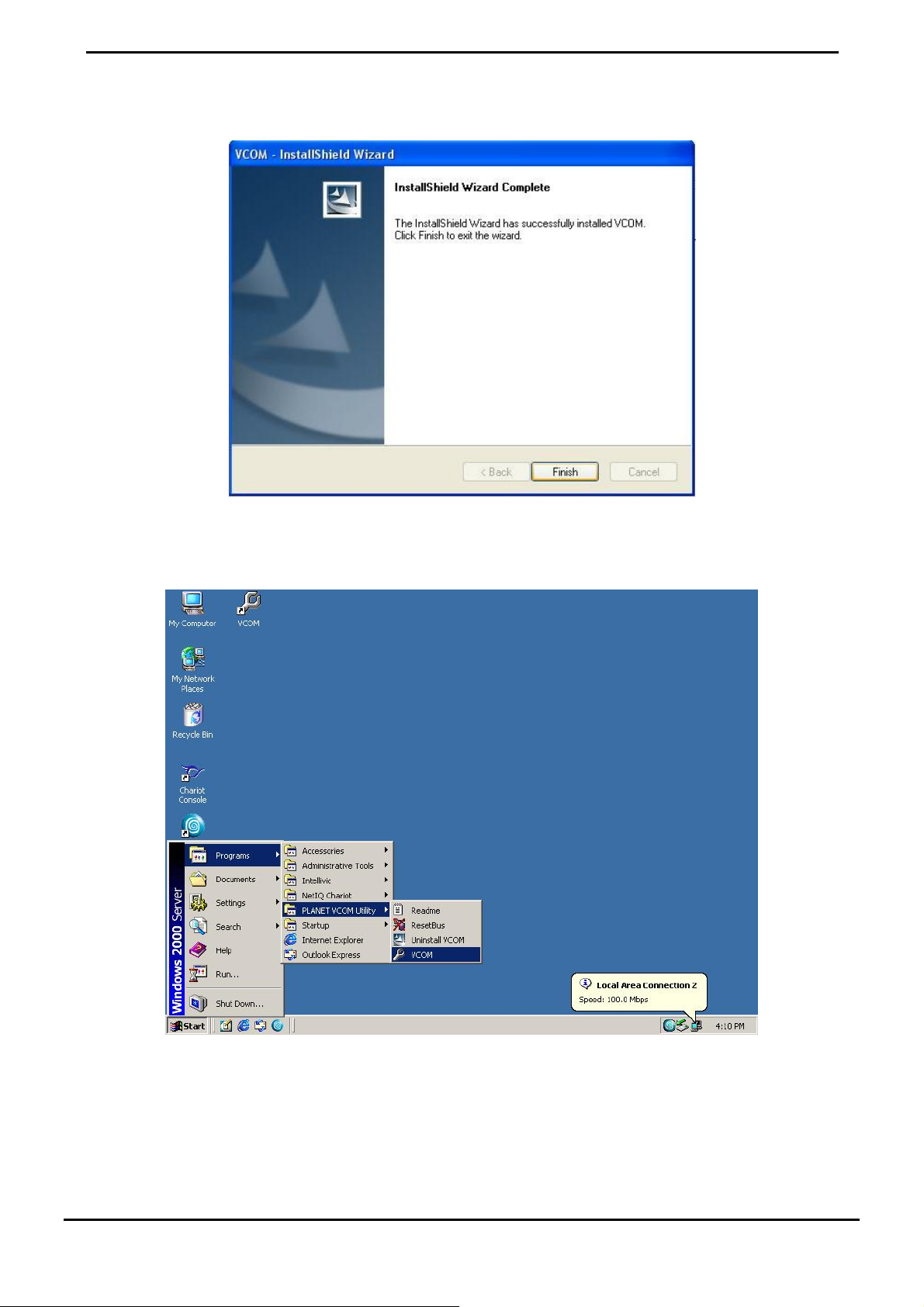
4. Click Fin ish to complete
User’s Manual of ICS-10x
Figure 5-3 VCOM installation screen
5. To run the PLANET VCOM utility on th e c omp ut e r, cli ck “Start” \ “Programs” \ “PLANET VOM Utility” \ “VCOM”
Figure 5-4 VCOM program path
The VCOM contains two pages: Search Device and VCOM. The Search Device has device information and the VCOM
show the virtual COM information.
-50-
Page 55

User’s Manual of ICS-10x
5.2 Search the Device
Click the Search Device button to find the ICS-10X. It will show the ICS-10X device name, project n ame, MAC address, IP
address, Sub Mask, Gateway and the connect port number.
1. Click the shortcut of VCOM on the desktop to run the VCOM program.
2. Click "Search Device" button in Search Device tab. If any ICS-10x series device on the LAN, it will show the devi ce
name in the tree report. While user click the device name, it will show device information in the list report.
Figure 5-5 VCOM Device Search
5.3 Virtual COM
This function should be set the ICS-10X’s operation mode to “Virtual COM” on the Web.
Choose to create port like below:
1. If the device support Telnet, while user click device name, it will show VCOM tab.
2. While user click VCOM tab, it will fill IP Address and Port number automatically.
3. Select COM Port Name
4. Click "Create Port" button to create new virtual com port and establish telenet connection
-51-
Page 56

User’s Manual of ICS-10x
Figure 5-6 VCOM Configuration
5. Then set the HyperTerminal parameter
Figure 5-7 Hyper Terminal Co nfiguration
6. then the VCOM will show connect information like below:
-52-
Page 57

User’s Manual of ICS-10x
Figure 5-8 VCOM Configuration
7. Once the Virtual COM Port- COM9 connection is established, fro m the Windows Device Manager, a COM Port is
added to the device list.
Figure 5-9 Windows Device Server - Virtual COM Port
When the Virtual COM create com port, the Device Manager will add “Virtual Serial Port”.
And delete the Port on the VCOM, the device will disappear.
-53-
Page 58

User’s Manual of ICS-10x
APPENDIX A
A.1 PLANET Smart Discovery Utility
For easily list the ICS-10X in your Ethernet environment, the Planet Smart Discovery Utility from user’s manual CD-ROM
is an ideal solution.
The following install instructions guiding you for run the Planet Smart Discovery Utility.
1. Deposit the Planet Smart Discovery Utility in administrator PC.
2. Run this utility and the following screen appears.
Figure A-1 Planet Smart Discovery Utility Screen
If there are two LAN cards or above in the same administrator PC, choose different LAN card by
use the “Select Adapter” tool.
3. Press “Refresh” button for list current connected devices in the discovery list, the screen is shown as follow.
Figure A-2 Planet Smart Discovery Utility Screen
-54-
Page 59

User’s Manual of ICS-10x
1. This utility show all necessary information from the devices, such as MAC Address, Device Name, firmware version,
Device IP Subnet address, also can assign new password, IP Subnet address and description for the devices.
2. After setup completed, press “Update Device”, “Update Multi” or “Update All” button to take affect. The meaning of
the 3 buttons above are shown as below:
Update Device: use current setting on one single device.
Update Multi: use current setting on choose multi-devices.
Update All: use current setting on whole devices in the list.
The same functions mentioned above also can be finding in “Option” tools bar.
3. To click the “Control Packet Force Broadcast” function, it can allow assign new setting value to the Web Smart
Switch under different IP subnet address.
6. Press “Connect to Device” button then the Web login screen appears.
7. Press “Exit” button to shutdown the planet Smart Discovery Utility.
A.2 Device‘s RJ-232/RS-422/RS-485 Pin Assignments
¾ DB9 Pin Define for RS-232 / RS-422 / RS-485
DB9-PIN RS-232
1 DCD
2 RXD
3 TXD
4 DTR RX- Data B(-)
5 GND
6 DSR TX-
7 RTS RX+ Data A(+)
8 CTS TX+
9 RI
RS-422/485
4-wire
RS-485
2-wire
A.3 Device‘s RJ-45 Pin Assignments
■ 10/100Mbps, 10/100Base-TX
Contact MDI MDI-X
1 1 (TX +) 3
2 2 (TX -) 6
3 3 (RX +) 1
6 6 (RX -) 2
4, 5, 7, 8 Not used Not used
Implicit implementation of the crossover function within a twisted-pair cable, or at a wiring panel , w hile not expressly
forbidden, is beyond the scope of this standard.
-55-
Page 60
User’s Manual of ICS-10x
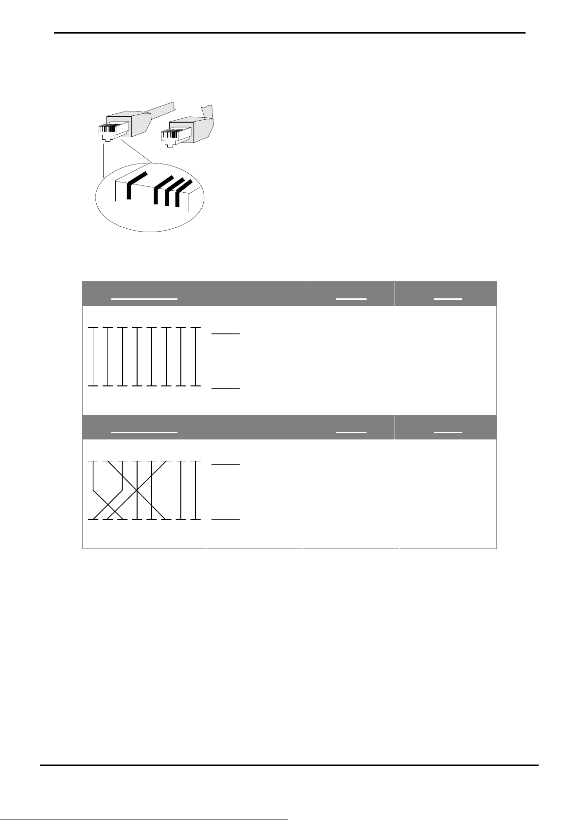
A.4 RJ-45 cable pin assignment
2 1
3 6
6
There are 8 wires on a standard UTP/STP cable and each wire is color-coded. The following shows the pin allocation
and color of straight cable and crossover cable connection:
Straight Cable SIDE 1 SIDE2
3
2136
2
1
12345678
12345678
SIDE 1
SIDE 2
1 = White / Orange
2 = Orange
3 = White / Green
4 = Blue
5 = White / Blue
6 = Green
7 = White / Brown
8 = Brown
1 = White / Orange
2 = Orange
3 = White / Green
4 = Blue
5 = White / Blue
6 = Green
7 = White / Brown
8 = Brown
Straight Cable SIDE 1 SIDE2
12345678
12345678
Please make sure your connected cables are with same pin assignment and color as above picture before deploying the
cables into your network.
SIDE 1
SIDE 2
Figure A-1: Straight-Through and Crossover Cable
1 = White / Orange
2 = Orange
3 = White / Green
4 = Blue
5 = White / Blue
6 = Green
7 = White / Brown
8 = Brown
1 = White / Orange
2 = Green
3 = White / Orange
4 = Blue
5 = White / Blue
6 = Orange
7 = White / Brown
8 = Brown
-56-
Page 61

User’s Manual of ICS-10x
A.5 Fiber Optical Cable Connection Parameter
The wiring details are as below:
■ Fiber Optical patch Cables: (For ICS-102 / ICS-102S)
Standard Fiber Type Cable Specification
100Base-FX
(1300nm)
(1310nm)
Multi-mode 50/125μm or 62.5/125μm
Multi-mode 50/125μm or 62.5/125μm 100Base-FX
Single-mode 9/125μm
A.6 Power Information
The power jack of ICS-10X is with 2.5mm in the central post and required +5VDC power input. It will conform to the
bundled AC-DC adapter and Planet’s Media Chassis. Should you have the problem to make the power connection, please
contact your local sales representative.
Please keep the AC-DC adapter as spare parts when your ICS-10X is installed to a Media Chassis.
2.5mm
DC Receptacle 2.5mm
DC receptacle is 2.5mm wide that co nf o rm s to a nd m atch e s the Me di a Co nv erter 2.5mm DC
jack's central post. Do not install any improper unit, model of the Media Converter
2080-AA3600-000
+5V for each slot
-57-
Page 62

EC Declaration of Conformity
For the following equipment:
*Type of Product : RS-232 / RS-422 / RS-485 over 10/100Base-TX Media Converter
(1 DB9, 1 RJ-45)
*Model Number : ICS-100
* Produced by:
Manufacturer‘s Name : Planet Technology Corp.
Manufacturer‘s Address : 11F, No. 96, Min Chuan Road, Hsin Tien
Taipei, Taiwan , R. O.C.
is herewith confirmed to comply with the requirements set out in the Council Directive on the
Approximation of the Laws of the Member States relating to Electromagnetic Compatibility
Directive on (89/336/EEC).
For the evaluation regarding the EMC, the following standards were applied:
Emission EN 55022 (1994 + A1:1995 + A2:1997
Class A)
Harmonic EN 61000-3-2 (2000)
Flicker EN 61000-3-3 (1995 + A1:2001)
Immunity EN 55024 (1998)
ESD IEC 61000-4-2 (1995 + A1:1998 + A2:2000)
RS IEC 61000-4-3 (1995 + A1:1998 + A2:2000)
EFT/ Burst IEC 61000-4-4 (1995 + A1:2000)
Surge IEC 61000-4-5 (1995 + A1:2000)
CS IEC 61000-4-6 (1996 + A1:2000)
Magnetic Field IEC 61000-4-8 (1993 + A1:2000)
Voltage Disp IEC 61000-4-11 (1994 + A1:2000)
Responsible for marking this declarati o n i f the:
⌧ Manufacturer Authorized representative established within the EU
Authorized representative established within the EU (if applicable):
Company Name: Planet Technology Corp.
Company Address: 11F, No.96, Min Chuan Road, Hsin Tien, Taipei, Taiwan, R.O.C
Person responsible for making this declaration
Name, Surname Kent Kang
Position / Title : Product Manager
Taiwan
18, March., 2008
Place Date Legal Signature
PLANET TECHNOLOGY CORPORATION
e-mail: sales@planet.com.tw http://www.planet.com.tw
11F, No. 96, Min Chuan Road, Hsin Tien, Taipei, Taiwan, R.O.C. Tel:886-2-2219-9518 Fax:886-2-2219-9528
Page 63

EC Declaration of Conformity
For the following equipment:
*Type of Product : RS-232 / RS-422 / RS-485 over 100Base-FX Media Converter
(1 DB9, 1 Fiber SC connector)
*Model Number : ICS-102 / ICS-102S15 / ICS-105A
* Produced by:
Manufacturer‘s Name : Planet Technology Corp.
Manufacturer‘s Address : 11F, No. 96, Min Chuan Road, Hsin Tien
Taipei, Taiwan , R. O.C.
is herewith confirmed to comply with the requirements set out in the Council Directive on the
Approximation of the Laws of the Member States relating to Electromagnetic Compatibility
Directive on (89/336/EEC).
For the evaluation regarding the EMC, the following standards were applied:
Emission EN 55022 (1994 + A1:1995 + A2:1997
Class A)
Harmonic EN 61000-3-2 (2000)
Flicker EN 61000-3-3 (1995 + A1:2001)
Immunity EN 55024 (1998)
ESD IEC 61000-4-2 (1995 + A1:1998 + A2:2000)
RS IEC 61000-4-3 (1995 + A1:1998 + A2:2000)
EFT/ Burst IEC 61000-4-4 (1995 + A1:2000)
Surge IEC 61000-4-5 (1995 + A1:2000)
CS IEC 61000-4-6 (1996 + A1:2000)
Magnetic Field IEC 61000-4-8 (1993 + A1:2000)
Voltage Disp IEC 61000-4-11 (1994 + A1:2000)
Responsible for marking this declarati o n i f the:
⌧ Manufacturer Authorized representative established within the EU
Authorized representative established within the EU (if applicable):
Company Name: Planet Technology Corp.
Company Address: 11F, No.96, Min Chuan Road, Hsin Tien, Taipei, Taiwan, R.O.C
Person responsible for making this declaration
Name, Surname Kent Kang
Position / Title : Product Manager
Taiwan
24, March., 2008
Place Date Legal Signature
PLANET TECHNOLOGY CORPORATION
e-mail: sales@planet.com.tw http://www.planet.com.tw
11F, No. 96, Min Chuan Road, Hsin Tien, Taipei, Taiwan, R.O.C. Tel:886-2-2219-9518 Fax:886-2-2219-9528
 Loading...