

Page 1

Wired / Wireless
USB2.0 MFP Print Server
FPS-1010M / FPS-1010MG
User’s Manual
Version: 2.0
(January, 2008)
Page 2

Copyright
Copyright© 2008 by PLANET Technology Corp. All rights reserved. No part of this
publication may be reproduced, transmitted, transcribed, stored in a retrieval system, or
translated into any language or computer language, in any form or by any means,
electronic, mechanical, magnetic, optical, chemical, manual or otherwise, without the prior
written permission of PLANET.
PLANET makes no representations or warranties, either expressed or implied, with respect
to the contents hereof and specifically disclaims any warranties, merchantability or fitness
for any particular purpose. Any software described in this manual is sold or licensed "as
is". Should the programs prove defective following their purchase, the buyer (and not this
company, its distributor, or its dealer) assumes the entire cost of all necessary servicing,
repair, and any incidental or consequential damages resulting from any defect in the
software. Further, this company reserves the right to revise this publication and to make
changes from time to time in the contents hereof without obligation to notify any person of
such revision or changes.
All brand and product names mentioned in this manual are trademarks and/or registered
trademarks of their respective holders.
Federal Communication Commission Interference Statement
This equipment has been tested and found to comply with the limits for a Class B digital
device, pursuant to Part 15 of FCC Rules. These limits are designed to provide
reasonable protection against harmful interference in a residential installation. This
equipment generates, uses, and can radiate radio frequency energy and, if not installed
and used in accordance with the instructions, may cause harmful interference to radio
communications. However, there is no guarantee that interference will not occur in a
particular installation. If this equipment does cause harmful interference to radio or
television reception, which can be determined by turning the equipment off and on, the
user is encouraged to try to correct the interference by one or more of the following
measures:
1. Reorient or relocate the receiving antenna.
2. Increase the separation between the equipment and receiver.
3. Connect the equipment into an outlet on a circuit different from that to which the
receiver is connected.
4. Consult the dealer or an experienced radio technician for help.
FCC Caution:
To assure continued compliance.(example-use only shielded interface cables when
connecting to computer or peripheral devices). Any changes or modifications not expressly
approved by the party responsible for compliance could void the user’s authority to operate
the equipment.
This device complies with Part 15 of the FCC Rules. Operation is subject to the Following
two conditions: (1) This device may not cause harmful interference, and (2) this Device
must accept any interference received, including interference that may cause undesired
operation.
Federal Communication Commission (FCC) Radiation Exposure Statement
This equipment complies with FCC radiation exposure set forth for an uncontrolled
environment. In order to avoid the possibility of exceeding the FCC radio frequency
exposure limits, human proximity to the antenna shall not be less than 20 cm(8 inches)
during normal operation.
R&TTE Compliance Statement
This equipment complies with all the requirements of DIRE CTIVE 1999/5/CE OF THE
EUROPEAN PARLIAMENT AND THE COUNCIL OF 9 March 1999 on radio equipment and
Page 3

telecommunication terminal Equipment and the mutual recognition of their conformity
(R&TTE)
The R&TTE Directive repeals and replaces in the directive 98/13/EEC (Telecommunications
Terminal Equipment and Satellite Earth Station Equipment) As of A pril 8,2000.
Safety
This equipment is designed with the utmost care for the safety of those who install and use
it. However, special attention mu st be paid to the dangers of electric shock and static
electricity when working with electrical equipment. All guidelines of this and of the computer
manufacture must therefore be allowed at all times to ensure the safe use of the equipment.
WEEE regulation
To avoid the potential effects on the environment and human health as a result of
the presence of hazardous substances in electrical and electronic equipment, end
users of electrical and electronic equipment should understand the meaning of the
crossed-out wheeled bin symbol. Do not dispose of WEEE as unsorted municipal
waste and have to collect such WEEE separately.
Revision
User’s Manual for PLANET Wired / Wireless USB2.0 MFP Print Server
Model: FPS-1010Mv2 / FPS-1010MGv2
Rev: 2.0 (January, 2008)
Part No. EM-FPS1010M_MGv2
Page 4

Contents
1. Introduction ............................................................................................................................. 1
2. Product Package..................................................................................................................... 1
3. MFP Server Installation in Windows 2000/XP/Vista............................................................... 2
3.1 Hardware Installation............................................................................................. 2
3.2 Software Installation Procedure............................................................................. 2
3.3 Install the MFP Drivers/Utilities.............................................................................. 9
4. Using the MFP...................................................................................................................... 14
4.1 Share Printer and Fax ......................................................................................... 14
4.2 Share Scanner..................................................................................................... 15
4.3 Share Card Reader .............................................................................................16
5. MFP Server Control Manager............................................................................................... 17
5.1 MFP Server List................................................................................................... 17
5.2 My Favorite.......................................................................................................... 18
5.3 Auto Connect List ................................................................................................ 19
5.4 Option Settings.................................................................................................... 21
5.4.1 General Setting............................................................................................21
5.4.2 Search for MFP Server................................................................................22
6. Server Management ............................................................................................................. 23
6.1 Introduction.......................................................................................................... 23
6.2 Status................................................................................................................... 24
6.3 Setup ................................................................................................................... 25
6.3.1 General Configuration..................................................................................26
6.3.2 TCP/IP Configuration...................................................................................27
6.3.3 System Configuration...................................................................................28
6.3.4 Wireless Configuration (FPS-1010MG Only)...............................................29
6.3.5 MFP Server Management............................................................................39
6.4 Report.................................................................................................................. 40
7. Web Management................................................................................................................. 41
7.1 Introduction.......................................................................................................... 41
7.2 Login.................................................................................................................... 41
7.3 Device Setup ....................................................................................................... 42
7.3.1 System.........................................................................................................42
7.3.2 Printer ..........................................................................................................43
7.3.3 TCP/IP .........................................................................................................43
7.4 Setup Wizard....................................................................................................... 44
7.4.1 System.........................................................................................................44
7.4.2 Wireless (FPS-1010MG Only).....................................................................46
7.4.3 TCP/IP .........................................................................................................50
7.4.4 Save Settings...............................................................................................51
7.5 System Tools ....................................................................................................... 51
7.5.1 Load Default.................................................................................................51
7.5.2 Upgrade .......................................................................................................52
7.5.3 Backup System............................................................................................52
7.5.4 Restore System ...........................................................................................52
8. LPR Printing.......................................................................................................................... 53
9. RAW Printing......................................................................................................................... 60
10. IPP Printing........................................................................................................................... 67
10.1 Introduction.......................................................................................................... 67
10.2 System Setup ...................................................................................................... 67
10.2.1 MFP Server Side..........................................................................................67
10.2.2 Client Side....................................................................................................67
11. UNIX System Network.......................................................................................................... 71
11.1 Introduction.......................................................................................................... 71
11.2 Enable MFP Server’s TCP/IP Support................................................................ 71
Page 5

11.3 Setup MFP Server’s IP Address.......................................................................... 71
11.3.1 DHCP...........................................................................................................72
11.3.2 BOOTP ........................................................................................................72
11.4 Verify MFP Server’s IP Address.......................................................................... 73
11.5 Configure Remote LPD Printing on the Host....................................................... 73
12. MFP Server Installation in MAC OS ..................................................................................... 75
13. Troubleshooting.................................................................................................................... 79
Appendix A: MFP Server Compatibility List................................................................................... 81
Page 6

1. Introduction
Thank you for purchasing and using our MFP print server. The FPS-1010M / FPS-1010MG
allows your Multi-function printer (called for short: MFP) or printer to become a shared device
on the network. Unlike many print servers, it can communicate with MFP and printer as if it is
connected directly to your c omputer. Because of the features, all users can share print, scan,
fax and card reader functions through the network. Furthermore, the FPS-1010M /
FPS-1010MG can build the bi-directional communication with MFPs and Printers so that it
can help to monitor important information such as ink levels and paper levels.
The FPS-1010M / FPS-1010MG supports print, scan, fax and card reader sharing functions in
Windows 2000 SP4 above and XP SP1 above. It also supports Windows XP scanning utility
and MFP vendors’ scanning utilities. When you want to scan in the Windows XP, you can
choose one of the utilities.
Not only be a MFP print server, this FPS-1010M / FPS-1010MG can also be a traditional print
server. It supports TCP/IP network protocol and LPR and IPP printing protocols. It can share
print function in the various common network operating systems including Windows
98SE/Me/NT/2000/XP/2003, Unix, Linux and MAC OS 9.x above. And it is GDI interface
supported. So it can co-work with the GDI printer.
The FPS-1010M / FPS-1010MG is the best solution for users to share MFP or printer
conveniently and easily. It offers the most flexibility and manageability for MFP or printer on
your Local Area Network at an extremely low cost and with an absolute minimum setup and
maintenance required.
2. Product Package
This package contains the following components:
One FPS-1010M / FPS-1010MG
One Power Adapter
One Quick Installation Guide
One CD-ROM (Including all the software utilities and User’s Manual)
One Dipole Antenna (For FPS-1010MG)
1
Page 7

3. MFP Server Installation in Windows 2000/XP/Vista
3.1 Hardware Installation
1. Unpack the FPS-1010M / FPS-1010MG package and verify the items listed in the previous
section are provided.
2. Use USB cable to connect FPS-1010M / FPS-1010MG to the MFP or printer that you want
to share to your network.
3. Use a RJ-45 cable to connect the FPS-1010M / FPS-1010MG to your LAN or WAN.
4. Connect the bundled power adapter to FPS-1010M / FPS-1010MG. The MFP Server will
perform the Power-On-Self-Test (POST) after power on. Please wait for 20 seconds.
NOTE: 1. Please use the power adapter which bundled with MFP Server. DO NOT use
any other power adapter from other sources. That may cause your FPS-1010M /
FPS-1010MG damage.
2. To prevent the compatibility problem between FPS-1010M / FPS-1010MG and a
few MFP or printer, it is recommended that you power on the FPS-1010M /
FPS-1010MG before the MFP or printer.
3.2 Software Installation Procedure
This FPS-1010M / FPS-1010MG management software can be run in Windows 2000 SP4 or
above, Windows XP SP1 or above and Windows Vista. The following procedures are running
in Windows XP, the procedures are similar for Windows 2000 and Windows Vista.
NOTE: Some MFP printers will ask the user connect MFP to the PC directly and install the
printer driver, before MFP Server installation. That may cause the MFP Server
installation adds one more MFP (printer/scanner/fax/card reader) to your PC. You
can delete the devices which the MFP driver installed after MFP Server installation,
or you can keep those devices exist in your PC.
1. Insert User’s Manual and utility CD into the CD-ROM drive to initiate the autorun program.
Once completed a menu screen will appear.
2. Click on “MFP Server Utility” hyper link to initiate the installation. Or you can click the
“Start” button and choose “Run”. (Suppose “E” is your CD-ROM drive). When the dialog
box appears, enter “E:\Utility\Setup.exe” and press enter key. You will see the dialog box
as below. Please click “Next” to continue.
2
Page 8
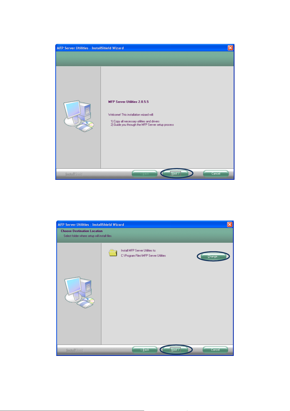
3. The “MFP Server Utilities - InstallShiled Wizard” is displayed, click "Next".
4. Click “Next” to install the MFP Server utilities in the default folder or click “Change” to
specify the destination folder where you would like to install the MFP Server utilities.
3
Page 9
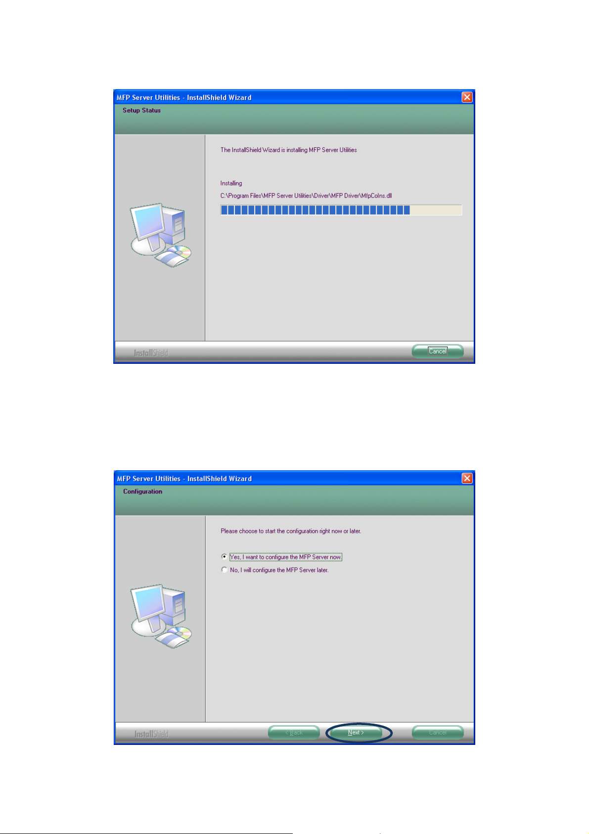
5. The system starts installing the MFP Server Utilities.
6. The “MFP Server Configuration” screen is displayed. If you want to configure the MFP
Server, please select “Yes, I want to configure the MFP Server now.” and click “Next”.
Then refer to the following steps to configure your MFP server. Or you can select “No, I
will configure the MFP Server later” and click “Next” to complete the installation.
4
Page 10
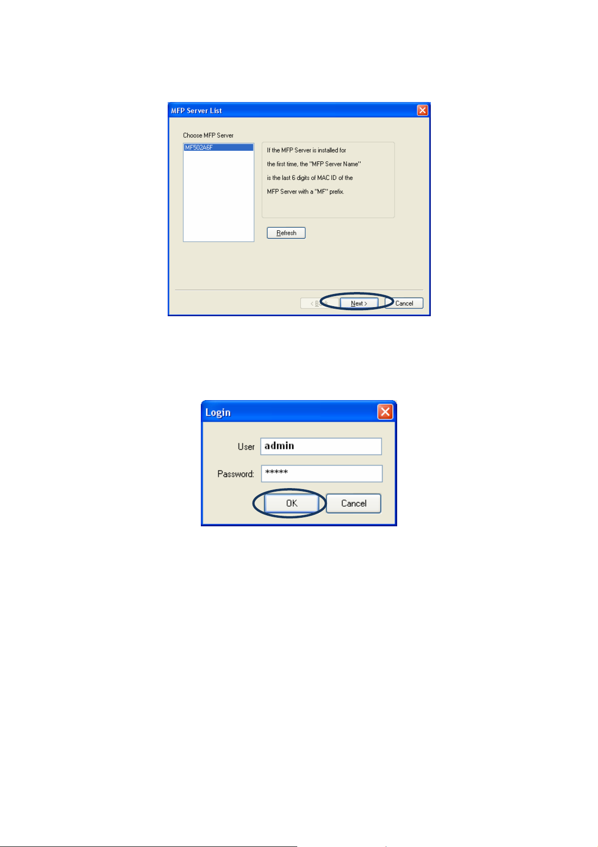
7. The MFP Server List will auto search the MFP Servers in the network. Select the MFP
Server you want to setup and click “Next” to continue.
8. Enter the “User Name” and “Password” of the MFP Server you have selected to login the
MFP Server. The default “User Name” and “Password” is “admin”. Click “OK”.
5
Page 11
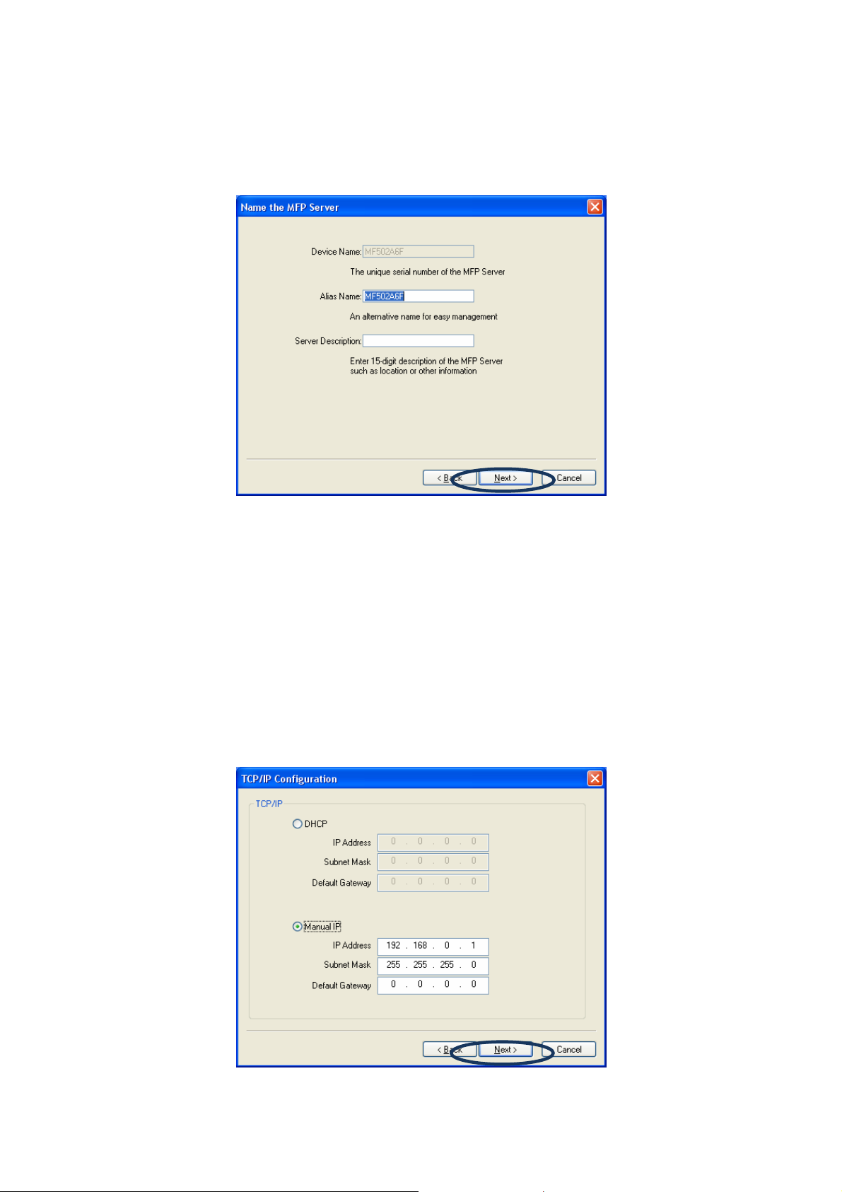
9. Set the “Alias Name” and the “MFP Server Description” to the MFP Server here. Click
“Next”.
NOTE: You can define the location or other information of the MFP Server for easy to
find the MFP by filling “MFP Server Description”.
10. Please set the network settings for the FPS-1010M / FPS-1010MG manually. The default
network value is as below:
IP Address: 192.168.0.1 Subnet Mask: 255.255.255.0
If you have selected “DHCP”, the FPS-1010M / FPS-1010MG will try to determine your
network settings automatically. The FPS-1010M / FPS-1010MG will automatically obtain
and configure the network settings assigned by the DHCP server and assigned IP
Address will be shown in the IP Address fields. If no DHCP server is present within the
network, please select “Manual IP” and assign the network settings of FPS-1010M /
FPS-1010MG manually. Please click “Next” to continue.
6
Page 12
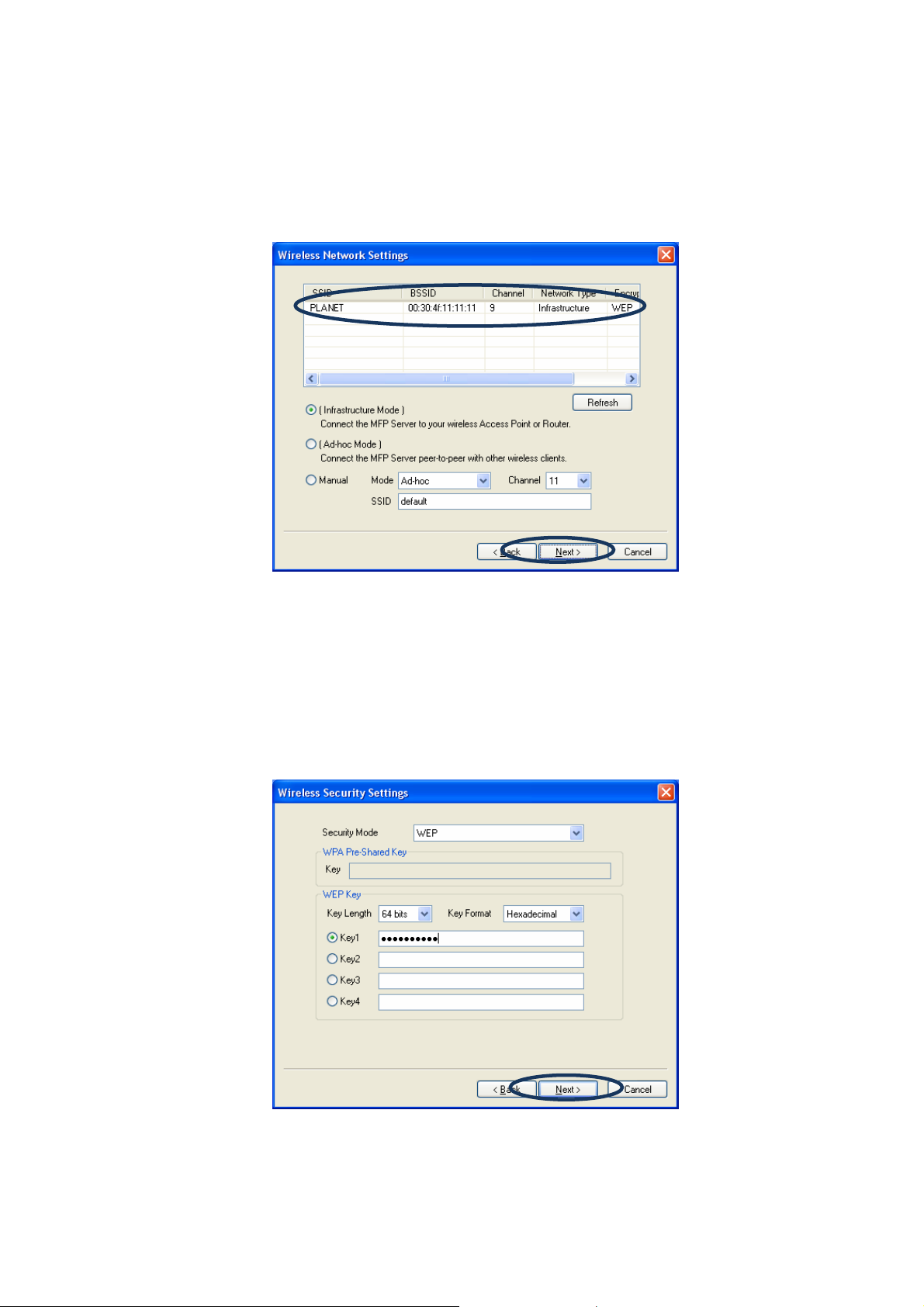
11. The FPS-1010MG will find available wireless network automatically. You could also press
the “Refresh” button to find the available wireless network manually. After refresh
procedure, there will show the available wireless networks. Please select the appropriate
wireless network that you would like to connect from the list and click “Next” to continue.
NOTE: Only FPS-1010MG has the “Wireless Network Settings” window.
12. If you choose to connect to an encrypted wireless network, the “Wireless Security
Settings“screen will be appeared. Please select the security mode, key length and key
format and key in the key value the same as the settings on your wireless devices. Please
click “Next” to continue.
NOTE: Only FPS-1010MG has the “Wireless Network Settings” window.
7
Page 13
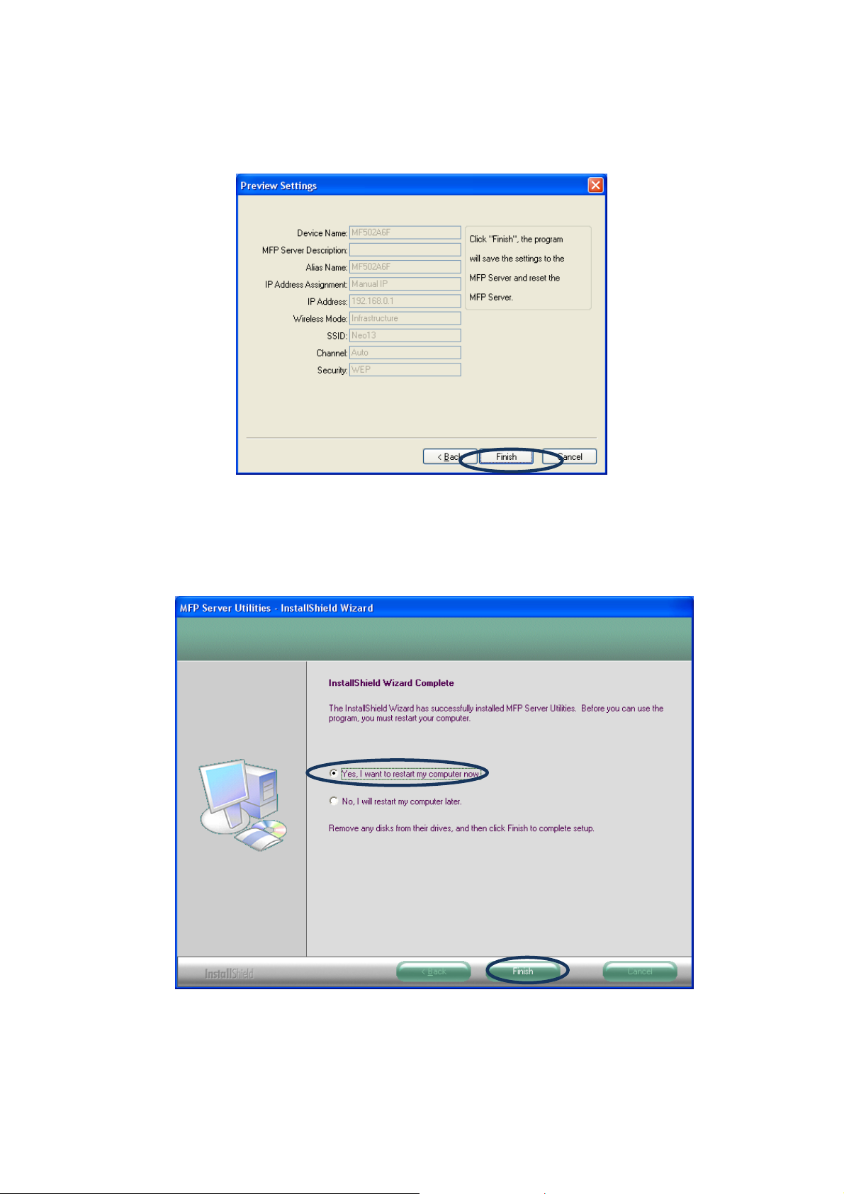
13. The configurations are finished. Please click “Finish” to apply new settings.
NOTE: Only FPS-1010MG shows the wireless mode, SSID, channel and security
information.
14. Select “Yes, I want to restart my computer now” and click “Finish” to complete the
installation.
8
Page 14
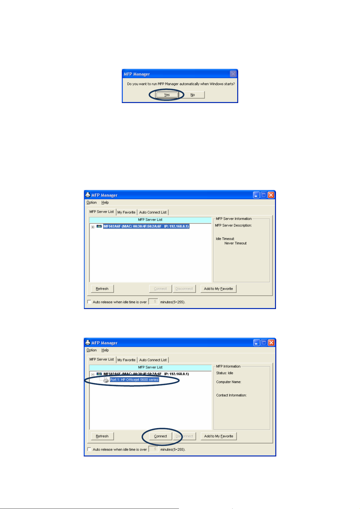
15. The “MFP Manager” will display on your screen automatically that after you install
management software finish and your computer get into Windows XP first time. Choose
“Yes” that enable “MFP Manager” utility automatically when Windows starts.
3.3 Install the MFP Drivers/Utilities
1. When the installation is completed, the “MFP Server Control Manager” will pop up. It will
automatically find the MFP Servers and the connected MFP and show it in the “MFP
Server List”. To start installing the MFP Drivers/Utilities, please follow the steps below.
2. Select the MFP which you want to install in the “MFP Sever List” and click “Connect”.
9
Page 15
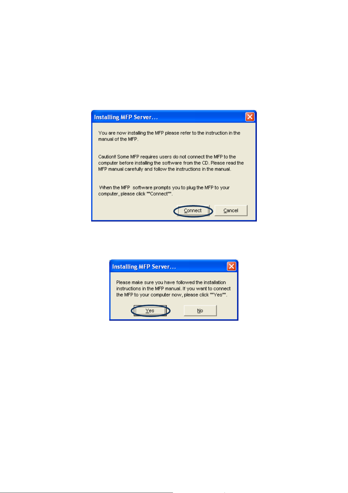
3. The following message is displayed to warn you that you have to follow the installation
instructions in the manual of the MFP. If the MFP is requiring you to connect the MFP to
your computer directly, please click “Connect”.
NOTE: Some MFP requires users to install the drivers/utilities before connecting the
MFP to your computer, please make sure you have followed the instructions of
MFP. When the MFP requires checking if you have connected the USB cable to
MFP and your computer, please click “Connect” to create the connection.
Please refer to the below illustration of “HP OfficeJet 5610” as an example.
4. If the MFP has required you to plug the USB cable between the MFP and your computer,
please click “Yes”.
10
Page 16
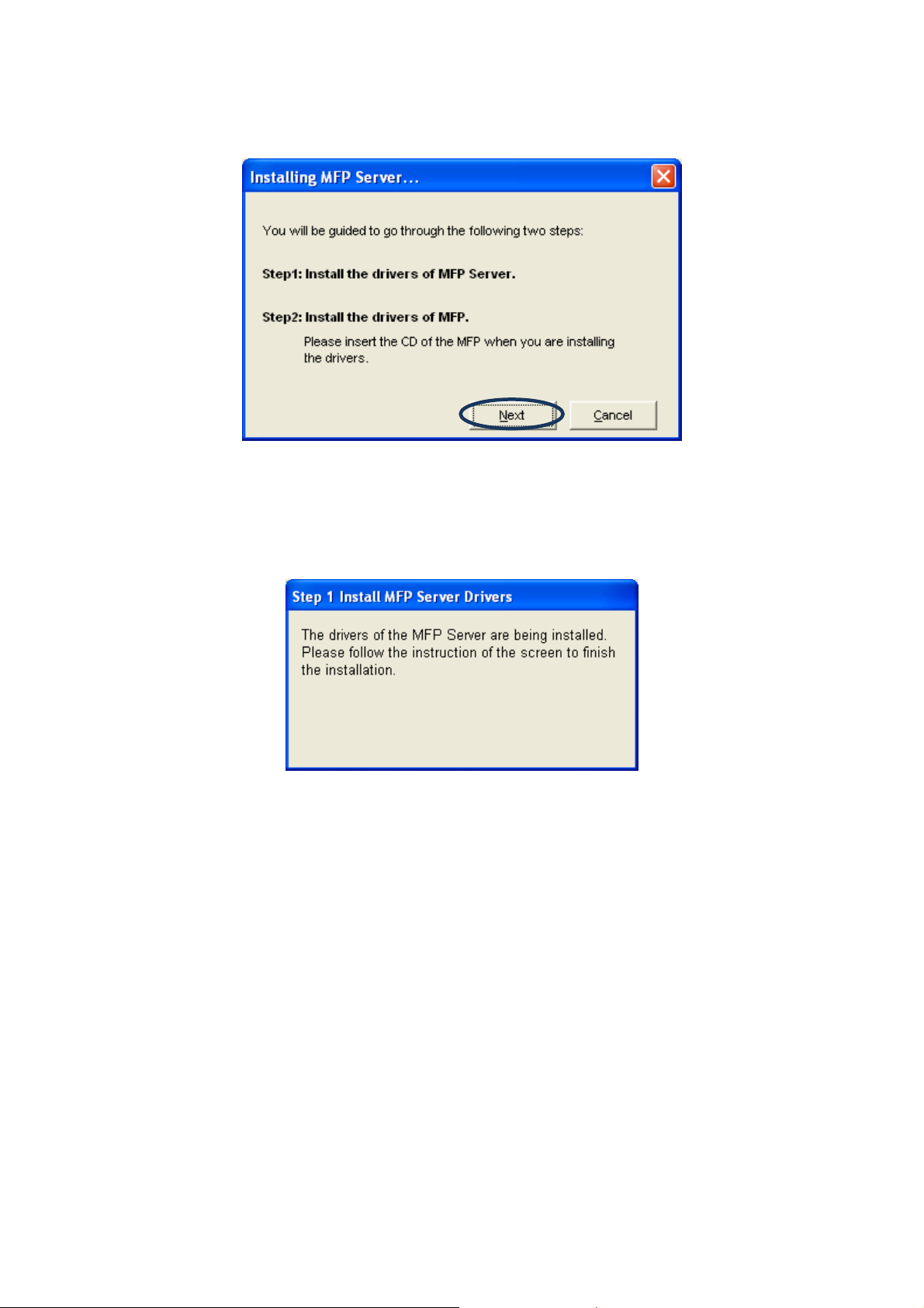
5. Before creating the connection, you have to install two kinds of drivers: the drivers for
MFP Server and the drivers for MFP. Please click “Next” to start the installation.
6. When you are installing the MFP Server Drivers, the following message will be displayed
to notify you. When the MFP Server drivers are all installed, the message will be
disappeared automatically.
11
Page 17
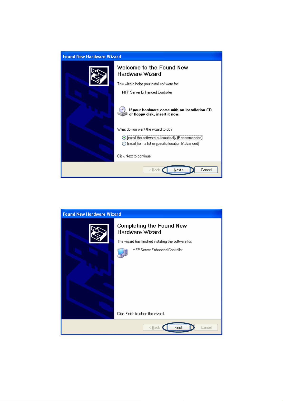
7. Select “Install the software automatically (Recommended)” to auto install the “MFP Server
Enhanced Controller” driver, and then click “Next”.
8. The driver will be installed automatically. Click “Finish” to complete this driver installation.
12
Page 18
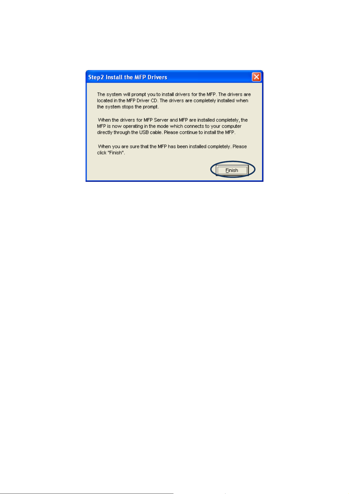
9. The following message is displayed to remind you that you are now installing the MFP
Drivers. When you are sure that the MFP has been connected to MFP Server and the
MFP driver CD is inserting to your CD-ROM completely, please click “Finish”.
10. Windows will start install the MFP. Please refer to your MFP manual and follow the steps
to install MFP driver and utility.
13
Page 19
4. Using the MFP
After you have followed the install wizard to finish the MFP installation, the MFP is now
connected to your computer. You can start sharing print, scan, fax and card reader functions
provided on the MFP.
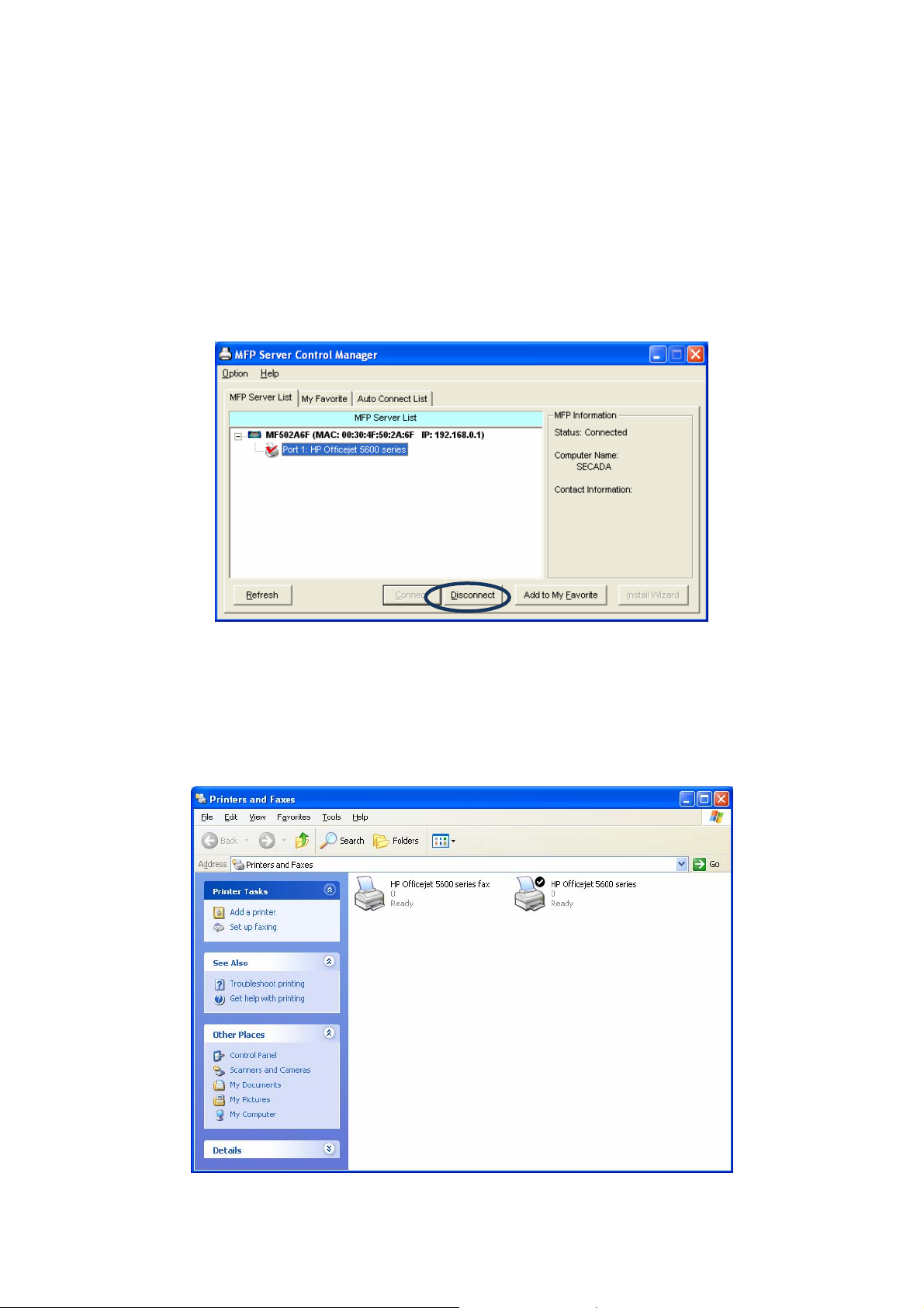
NOTE: If you have finished using the MFP, please click “Disconnect” to release the MFP
from your PC. When there is a user using or connecting MFP, the other users
can’t use the MFP until the MFP is released. You may refer to MFP Server
manual to setup the disconnect time to make the users auto-disconnect when the
MFP is no operation over the time.
4.1 Share Printer and Fax
The MFP will be added to “Printers and Faxes” after the MFP is installed. When you have
connected to the MFP by clicking “Connect” in the “MFP Server Control Manager”, the MFP
Server will auto create the connection between the MFP and your computer and then you can
print a document or send a fax just follows the same steps as usual.
14
Page 20
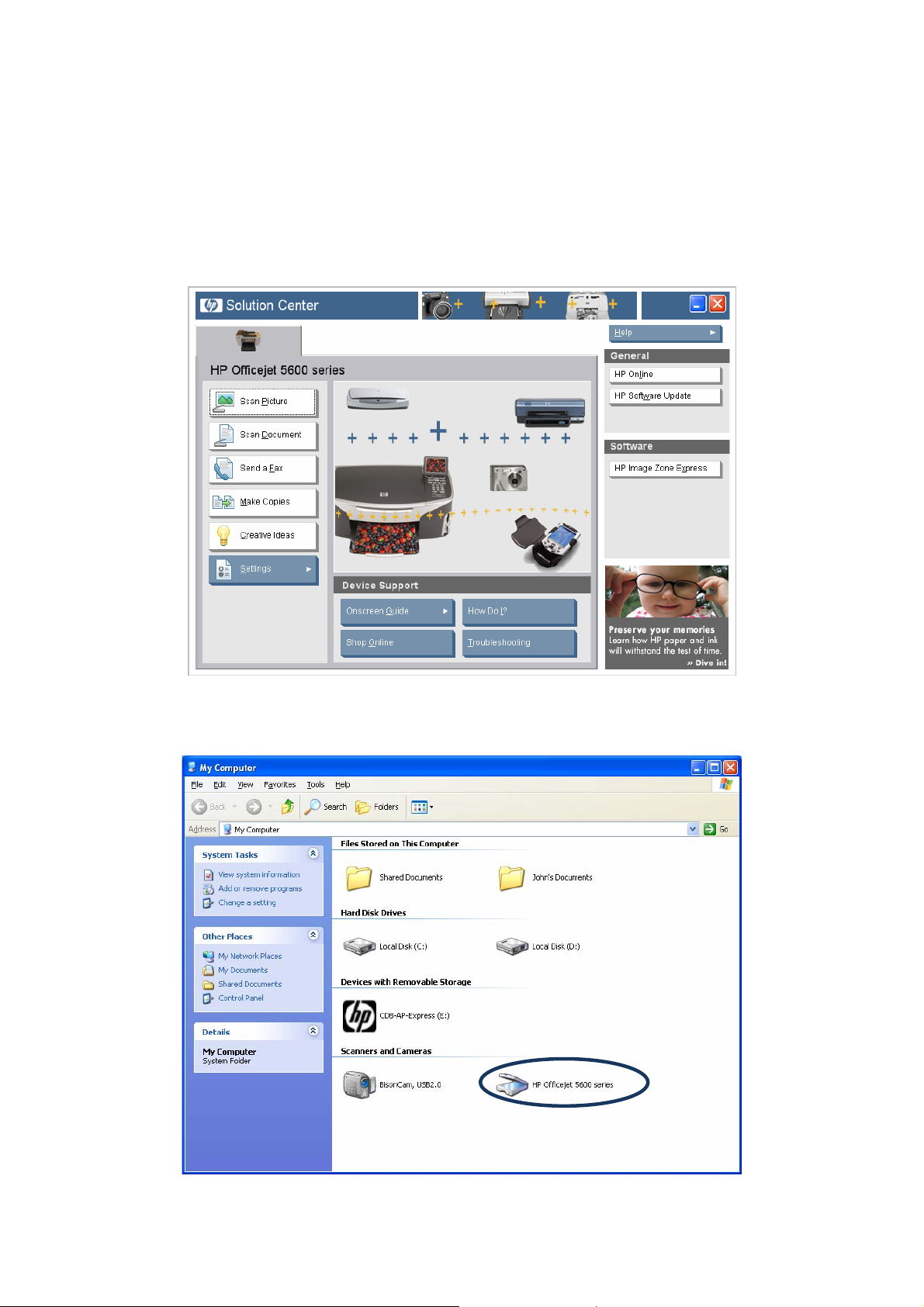
4.2 Share Scanner
Most of the MFP provides scan utility for users. You can scan pictures or documents through
the utility. In Windows XP, user can also scan from Windows XP scanning utility.
An example: HP 5600 Series Utilities
Windows XP Scanning Utility
15
Page 21
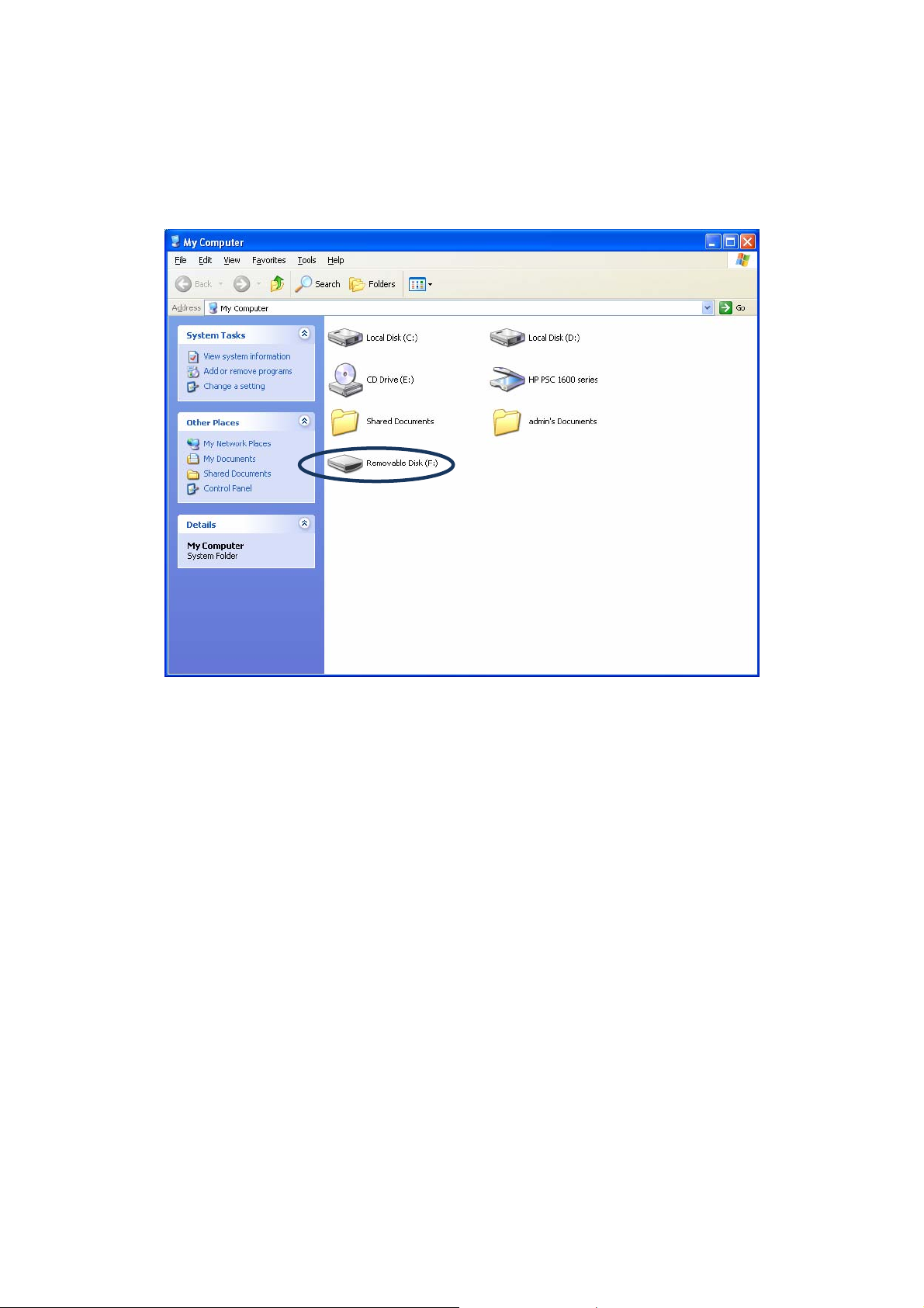
4.3 Share Card Reader
If the MFP supports card reader function, you can read the files from the plugged card reader
through the MFP Server.
16
Page 22
5. MFP Server Control Manager
5.1 MFP Server List
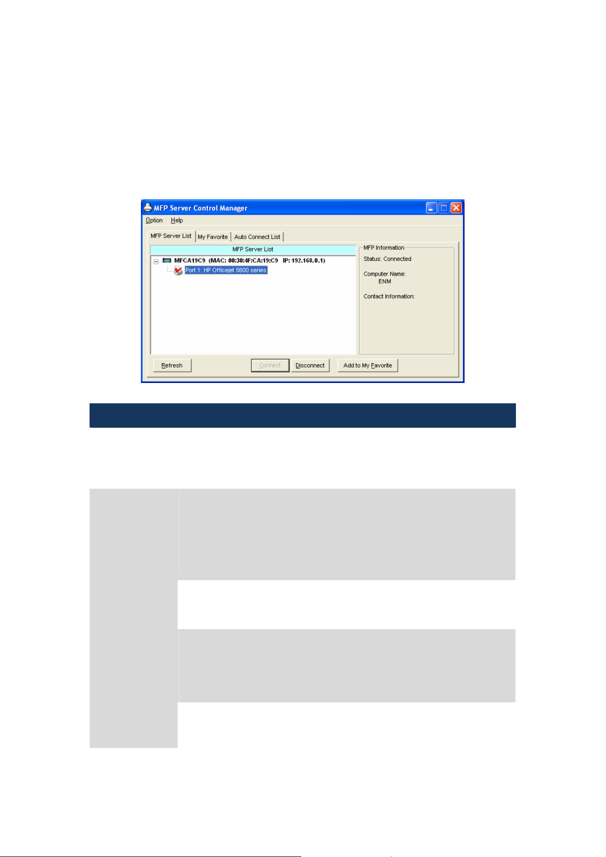
The “MFP Server Control Manager” can automatically find the MFP server in the network and
show it in the MFP Server List. Users can select a MFP and click “Connect” to connect the
MFP just like you have directly connected the MFP to your computer through USB cable. It
also displays the information of the connection status.
MFP Server List
MFP Server List The “MFP Server List” will list all the MFP Servers within the network. You
can find the information of the MFP Servers including “MFP Server
Name”, “MAC ID”, “IP Address” and the device that is connected to the
MFP Server.
MFP Information
When you are clicking on the “MFP Server” in the “MFP Server List”, you
will see the “MFP Server Description” and the “Idle Timeout” setting for the
MFP Server.
MFP Server Description – It is a description that can help users to
identify where or what the MFP Server is.
When you are clicking on the “MFP” in the “MFP Server List”, you will see
the information including “Status”, “Computer Name” and “Contact
Information”.
Status – It displays the status of the MFP including Connected, Idle and
Busy. When the status is “Connected”, it indicates that you are connecting
the MFP. When the status is “Idle”, it indicates that the MFP is not being
used. When the status is “Busy”, it indicates that other user is using the
MFP to scan, print, or etc.
Computer Name – It display the computer name of the user who is
connecting to the MFP.
17
Page 23
Contact Information – When the current user has set his “Contact
Information”, you can see it here. You can contact with the current user for
asking to disconnect the MFP.
Refresh Refresh the “MFP Server List” immediately.
Connect Let the MFP be connected to your computer.
Disconnect Disconnect the selected MFP.
Add to My
Favorite
Add the MFP Servers that you frequently use to “My Favorite List”.
5.2 My Favorite
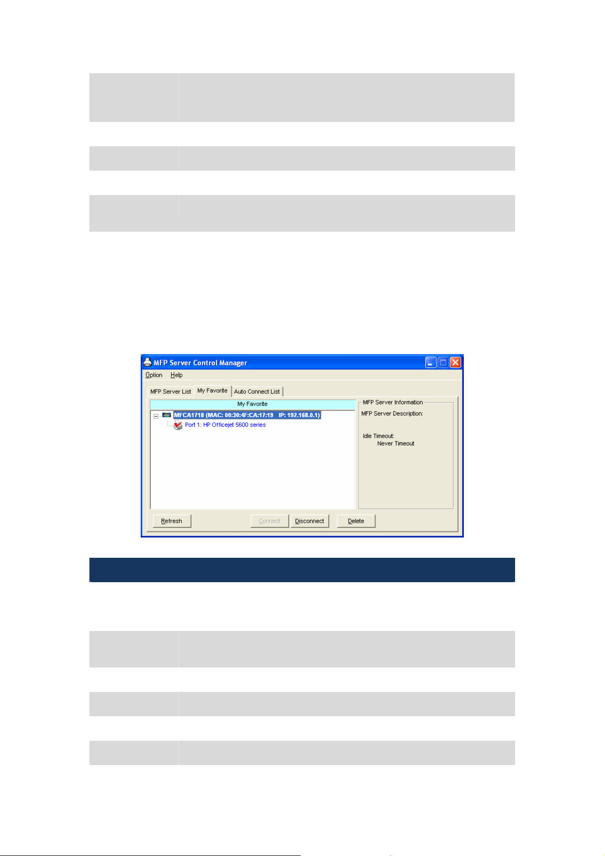
You can add the frequently use MFP Servers to “My Favorite” list. The MFP Server in the list
will be added to the quick link list when you right click the MFP Server icon in the system tray.
Please refer to Section 5.4 to know more about the quick setup functions.
My Favorite
My Favorite List The “My Favorite List” will list your favorite MFP Servers. You can find the
information of the MFP Servers including “MFP Server Name”, “MAC ID”,
“IP Address” and the device that is connected to the MFP Server.
MFP Server/MFP
Information
Refresh Refresh the “MFP Server List” immediately.
Connect Let the MFP be connected to your computer.
Disconnect Disconnect the selected MFP.
Delete Delete the selected MFP Server from the “My Favorite List”.
The information listed here are the same as MFP Server List. Please refer
to Section 5.1.
18
Page 24
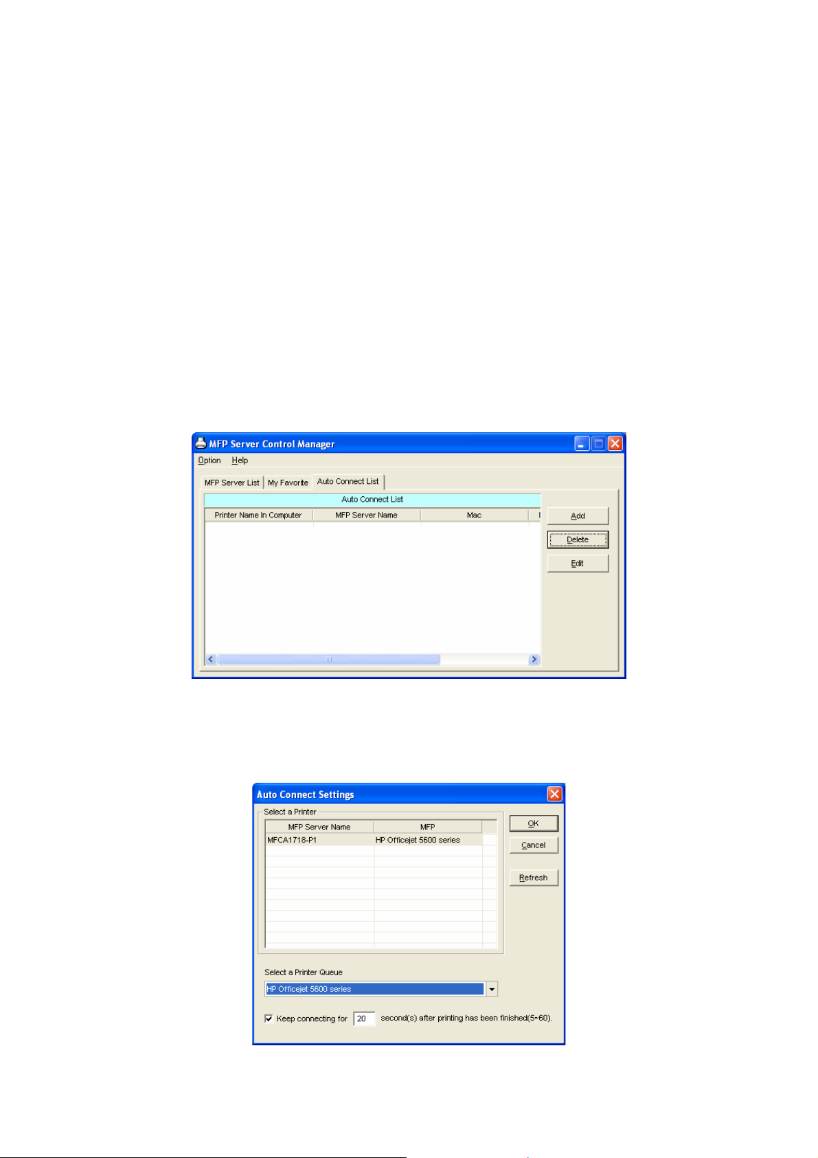
5.3 Auto Connect List
To let the system occupy the MFP server automatically when you want to print a document
just like the behavior of using traditional print server, you can add the MFP into your Auto
Connect List. The system will send the printing jobs to the MFP when the MFP Server is idle
and not being connected.
Note: If you have sent a printing job to the MFP while the MFP is busy or connected, you
may be prompt that the device is not found or not connected. The MFP may queue
your printing job in your computer spooler. The MFP Server will then print the job after
the MFP is idle or disconnected.
To add the MFP to the Auto Connect List, please follow the steps b elo w.
1. Click “Add” from the “Auto Connect List”.
2. The MFP Servers within the network will be displayed in the following screen. Select the
MFP Server you would like to add to the list.
19
Page 25
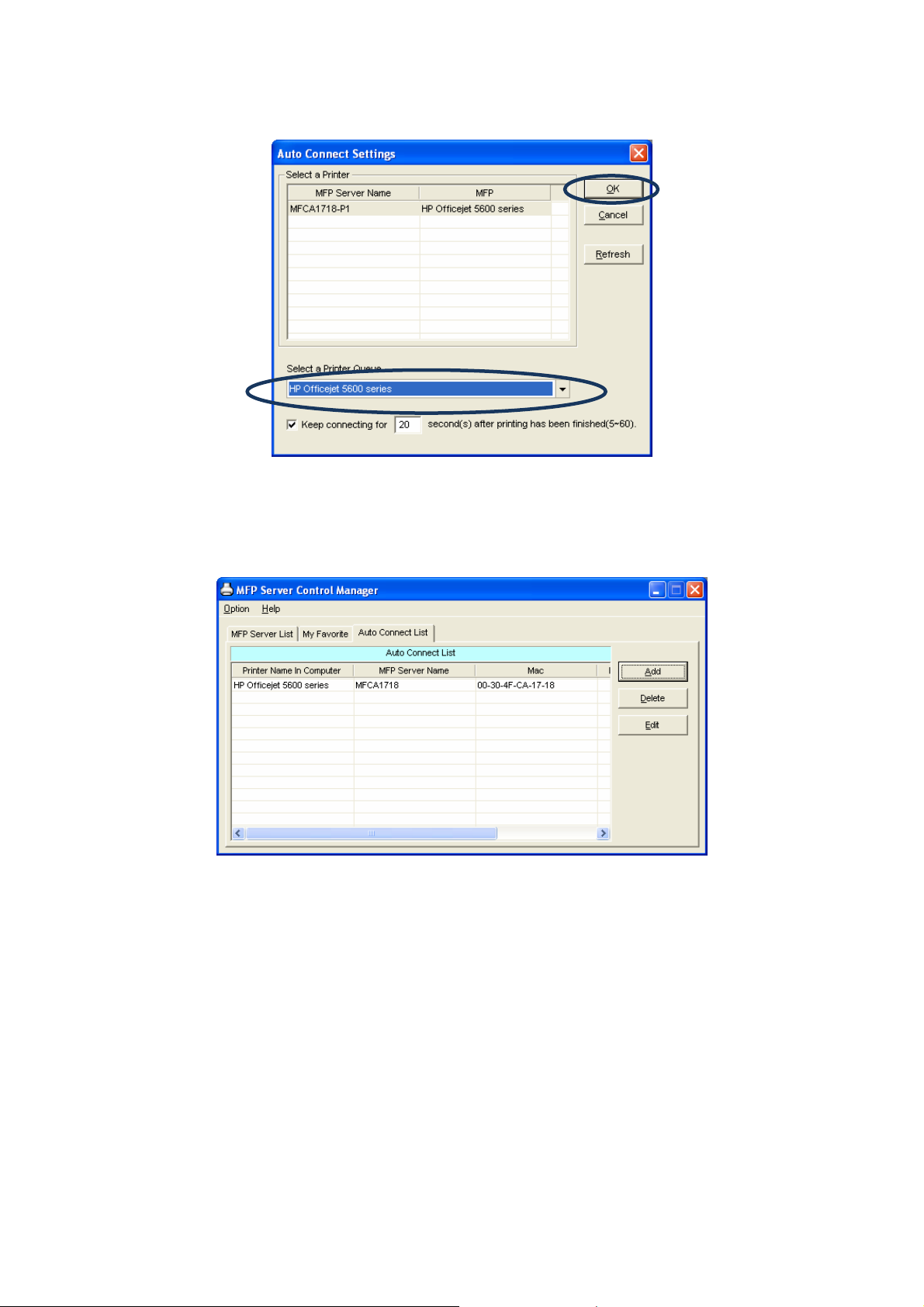
3. Select the MFP that is connected to the selected MFP Server. Click “Ok”.
4. The setup is finished.
20
Page 26
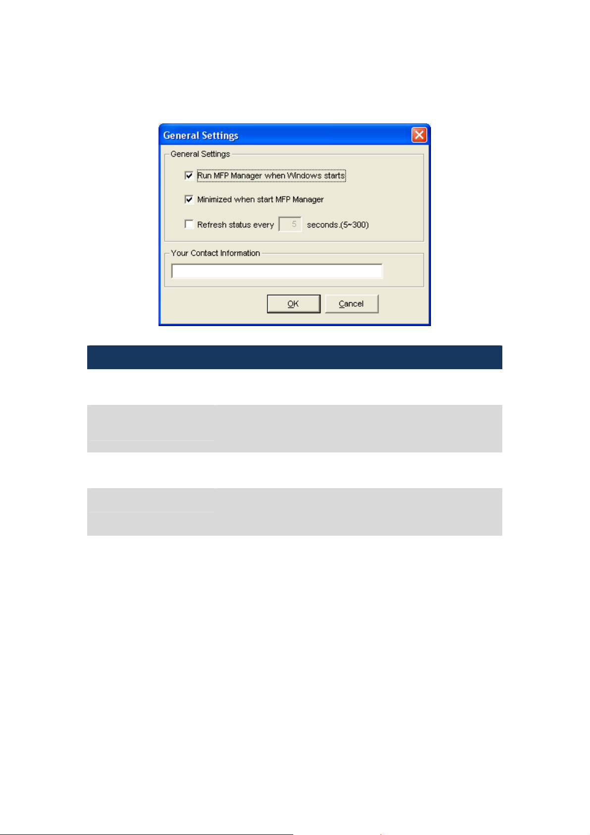
5.4 Option Settings
5.4.1 General Setting
General Setting
Run MFP Manager when
Windows starts
Minimized when start MFP
Manager
Refresh status every xx
seconds. (5~300)
Your Contract Information Enter your contact information here. When you connect to the
Execute the “MFP Server Control Manager” when Windows
starts every time. By default, it is enabled.
Minimized the “MFP Server Control Manager” to an icon in the
system tray when you start the “MFP Server Control Manager”.
By default, it is disabled.
Setup the refresh interval for device status update. By default, it
is disabled.
MFP, your contact information will be displayed in the right side
of the program for other users to contact you.
21
Page 27
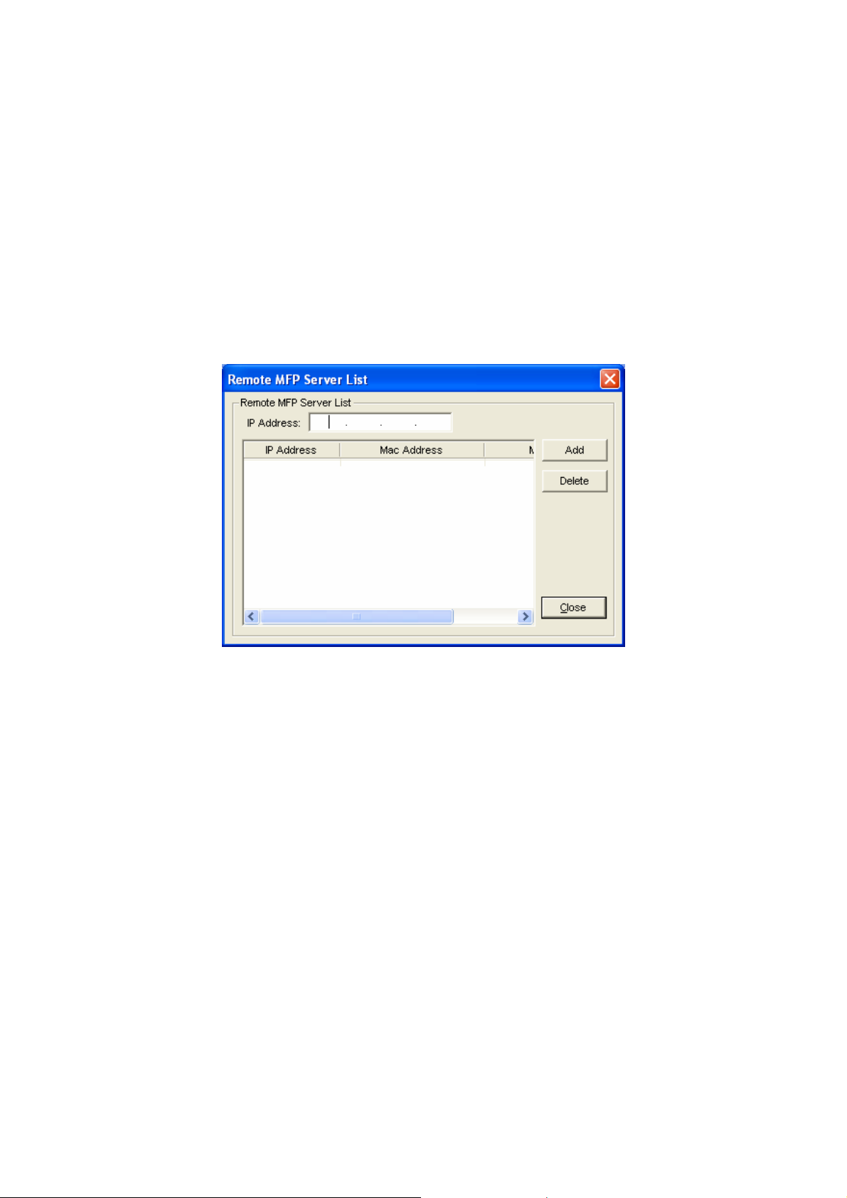
5.4.2 Search for MFP Server
If there is an MFP Server is not in the network as your computer, you can enter the IP
Address of the MFP Server to do the remote search. The MFP Server in the “Remote MFP
Server List” will be added to the “MFP Server List” for you to configure.
NOTE: If the remote MFP Server you have searched is behind NAT Router, the MFP Server
may not operate normally.
22
Page 28

6. Server Management
6.1 Introduction
This chapter introduces MFP Server’s system configuration utility in Windows environment.
This utility provides the most complete management and configuration functions on the MFP
Server side. This utility only provides configuration functions for MFP Server itself; it does not
include configuration functions for client side or other file server in the network environment.
The Configuration Utility provides the following configuration and management functions:
Server Management
Status: Display MFP Server Network Status.
Setup:
Configure the MFP Server detail settings.
General
Configuration:
TCP/IP
Configuration:
System
Configuration:
Wireless
Configuration:
Configure general settings about the MFP Server such
as Server Name, Password, etc.
IP Address and DHCP Server Configuration.
MFP Server Network Ability Setting and Firmware
Upgrade.
Configure wireless settings and operating mode.
NOTE: Only FPS-1010MG has the “Wireless
Configuration”.
MFP Server
Management:
Report: List the some information of all available MFP Servers on the Network.
For administrator to manage the MFP Server.
Administrator can force disconnect the current
connection and setup idle time out of the MFP Server.
23
Page 29

Refresh: Refresh the MFP Server’s status by pressing the “Refresh” button.
Reboot: Restart the MFP Server by pressing the “Reboot” button.
Search: Search all available MFP Servers on th e Network.
6.2 Status
Click “Status” icon
be showed on the right side of the window. The information of the MFP Server displayed are
including MAC ID, Model Type, Firmware Version, status of each server port, IP address,
subnet mask, default gateway and supported printing protocols…etc.
NOTE:
Only FPS-1010MG has the wireless information in the “Status” window.
on the tool bar, the status of the currently selected MFP Server will
24
Page 30

6.3 Setup
Click “Setup” icon
will be showed on the right side of the window.
Double click one of the icons to set up the selected MFP Server. A screen will pop up to verify
“User Name” and “Password” of the MFP Server. The default values are: User Name: admin,
Password: admin.
NOTE:
1. When you have finished the settings, please click “
Server to let the settings take effect.
2. Only FPS-1010MG has the “Wireless” button in the “Setup” window.
on the tool bar, the setup items of the current selected MFP Server
” to restart the MFP
25
Page 31

6.3.1 General Configuration
Double Click “General” icon and the General configuration window will pop-up.
You can see basic MFP Server information in this page. You also can configure the “Server
Name”, “User Name” and “Password” here.
Server Name:
User Name / Password:
The name of the MFP Server. You can use this name to identify
the MFP Server when you are searching for the MFP Server by
the “Server Manger” utility.
Be used to authenticate the administrator to login the MFP Server
for configuring it from the “Server Manger” utility or the Web
Management tool.
26
Page 32

6.3.2 TCP/IP Configuration
Double Click “TCP/IP” icon and the TCP/IP configuration window will pop-up.
You can configure the MFP Server to automatically get IP from DHCP server or manually
specify static IP.
When there is a DHCP Server in your network, you may select ‘Auto IP” of this dialog box to
let your MFP Server to obtain an IP address automatically. Or select the “Static IP” to enter
the “IP Address”, “Subnet Mask” and “Gateway” for this MFP Server.
27
Page 33

6.3.3 System Configuration
Double Click “System” icon and the System configuration window will pop-up.
In the System configuration page, you can see all available printing methods, firmware
upgrade and load factory default function.
Upgrade
Firmware:
NOTE: Before you upgrade the firmware, please make sure that the IP
Load
Default:
You can use this “Upgrade Firmware” tool to update the newest firmware of the
MFP Server. Click “ ” button and locate the correct firmware in your PC. After
find out the firmware, please click the “Upgrade” button to update firmware.
Address settings of the MFP Server are in the same network as your
computer.
If you want to reset the MFP Server to factory default settings, please click
“Load Default”. After load default, please press “ ” to reboot your MFP
Server to make the new configuration effect.
28
Page 34

6.3.4 Wireless Configuration (FPS-1010MG Only)
Due to wireless interface is “Auto” in default. If you want to use the print server through
wireless interface, please set up the MFP server through Ethernet firstly. After configure the
wireless LAN settings, unplug the Ethernet cable from the MFP server, then you can start to
use the MFP server via wireless interface. If the wireless configuration does not work, please
plug the Ethernet cable again and configure the print server through Ethernet until the
wireless LAN settings are correct. When the wireless interface work correctly, and you don’t
need to work with Ethernet interface, you may change the Wireless Function to “Enable” to
disable Ethernet interface.
You may select either Infrastructure Mode or Ad-hoc Mode for this print server to join your
wireless network.
6.3.4.1 Infrastructure Mode
If you are select “Infrastructure Mode” and click “Next” in section 7.11, you will see the dialog
box below. You can select first option to scan your wireless network to search the Access
Point that you want to connect. Or you can select the second option and enter the SSID you
had known into the field. Please choose one of them and click “Next”.
29
Page 35

2. When you are select first option to continue, you will see this screen for scan the wireless
network. Please select the wireless device that you want to connect and click “Next”. If
you don’t have see the wireless device that you would like to connected, please click
“Scan” to search again.
3. This print server supports WEP and WPA-PSK security mode. If you want to use WEP
encryption to protect your wireless network, you have to select “WEP(ASCII)” or
“WEP(HEX)”. If you want to use WPA-PSK, you have to select “WPA-shared key”. The
wireless security setting should be the same with other wireless devices in the same
network.
30
Page 36

WEP Security Mode:
You can select “64 bit” or “128 bit” length and “WEP(HEX)” or “WEP(ASCII)” format for the
encryption key. Longer key length can provide stronger security but worth communication
performance.
Enter four key values by following the rules below and select one key as the default key.
PassPhrase A passphrase simplifies the WEP encryption process by automatically
generating the WEP encryption keys for the print server. This setting is
only valid when the security mode is in “WEP(HEX)”.
Key 1 to Key 4 If the key length is 64-bit, enter 10-digit Hex values or 5-digit ASCII values
as the encryption keys. For example: “0123456aef“ or “Guest“.
If the key length is 128-bit, enter 26-digit Hex values or 13-digit ASCII values as the
encryption keys. For example: “01234567890123456789abcd ef“ or “administrator“.
31
Page 37

WPA-shared key Security Mode:
When “WPA-shared key”, also named “WPA-PSK” requires users to select the advanced
encryption methods, i.e. TKIP and enter a set of shared key.
WP A Algorithms TKIP - TKIP (Temporal Key Integrity Protocol) changes the temporal key
every 10,000 packets. This insures much greater security than the
standard WEP security
AES – AES has been developed to ensure the highest degree of
security and authenticity for digital information and it is the most
advanced solution defined by IEEE 802.11i for security in a wireless
network.
Shared Key Enter 8 to 63 digits of ASCII format to be the key for the authentication
within the network.
When you finish configuring the wireless security, click “Next” to go to next step.
32
Page 38

4. You can select to let the print server automatically obtain IP settings from DHCP Server or
manually assign the IP settings.
If you manually assign the IP settings, you have to enter IP address, subnet mask and
default gateway address. When you finish configuring the IP settings, click “Next” to
confirm the IP Address configuration.
5. Please click “Save” to save the wireless configuration.
6. You will see this dialog box to prompt you the settings will be saved. Please press “Yes” to
save.
33
Page 39

6.3.4.2 Ad-Hoc Mode
1. You can let the print server automatically associate with other wireless station or manually
assign the SSID of your wireless network. You can let the MFP server automatically
select the channel that is the same with the peer or manually assign a channel.
2. If you are select the first option to continue, you will see this screen for scan the wireless
network. Please select the wireless device that you want to connect and click “Next”. If
you don’t have see the wireless device that you would like to connected, please click
“Scan” to search again.
34
Page 40

3. This print server supports WEP and WPA-PSK security mode. If you want to use WEP
encryption to protect your wireless network, you have to select “WEP(ASCII)” or
“WEP(HEX)”. If you want to use WPA-PSK, you have to select “WPA-shared key”. The
wireless security setting should be the same with other wireless devices in the same
network.
35
Page 41

WEP Security Mode:
You can select “64 bit” or “128 bit” length and “WEP(HEX)” or “WEP(ASCII)” format for the
encryption key. Longer key length can provide stronger security but worth communication
performance.
Enter four key values by following the rules below and select one key as the default key.
PassPhrase A passphrase simplifies the WEP encryption process by automatically
generating the WEP encryption keys for the print server. This setting is
only valid when the security mode is in “WEP(HEX)”.
Key 1 to Key 4 If the key length is 64-bit, enter 10-digit Hex values or 5-digit ASCII values
as the encryption keys. For example: “0123456aef“ or “Guest“.
If the key length is 128-bit, enter 26-digit Hex values or 13-digit ASCII values as the
encryption keys. For example: “01234567890123456789abcd ef“ or “administrator“.
36
Page 42

WPA-shared key Security Mode:
When “WPA-shared key”, also named “WPA-PSK” requires users to select the advanced
encryption methods, i.e. TKIP and enter a set of shared key.
WP A Algorithms TKIP - TKIP (Temporal Key Integrity Protocol) changes the temporal key
every 10,000 packets. This insures much greater security than the
standard WEP security
AES – AES has been developed to ensure the highest degree of
security and authenticity for digital information and it is the most
advanced solution defined by IEEE 802.11i for security in a wireless
network.
Shared Key Enter 8 to 63 digits of ASCII format to be the key for the authentication
within the network.
When you finish configuring the wireless security, click “Next” to go to next step.
37
Page 43

4. You can select to let the print server automatically obtain IP settings from DHCP Server or
manually assign the IP settings.
If you manually assign the IP settings, you have to enter IP address, subnet mask and
default gateway address. When you finish configuring the IP settings, click “Next” to
confirm the IP Address configuration.
5. Please click “Save” to save the wireless configuration.
6. You will see this dialog box to prompt you the settings will be saved. Please press “Yes” to
save.
38
Page 44

6.3.5 MFP Server Management
Double Click “MFP Server Management” icon and the MFP Server configuration window will
pop-up. You are able to manage the MFP Server as below.
Force Release: Select the port number and then click “Force Release” will help to you
disconnect the current connection between the user and the connected
device. It is very useful when a user forgets to disconnect the MFP,
administrator can force to disconnect the connection and let the MFP be
free to use.
MFP Server
Description:
Enter 15 digits description of the MFP Server such as location or other
information to help user to find the MFP Server easily.
NOTE: After all users have installed the MFP successfully. It is
recommended that enable the “Auto Release when idle timeout”
setting in “MFP Server Control Manager” => “Option”, so that the
MFP resource will not be occupied easily by only one user.
39
Page 45

6.4 Report
Click “Report” icon
The report lists basic information of all available MFP Servers on the network. The information
includes Device Name, MAC ID, Model Type and Firmware Version of MFP Server.
on the tool bar, the Report window will pop up.
40
Page 46

7. Web Management
7.1 Introduction
MFP Server can be configured and managed by Web Browser. Through Local Area Network,
or even Internet, administrator can easily configure and manage MFP Server’s various main
functions in browsers. Simply enter MFP Server’s IP address into your browser’s address field
to manage a MFP Server by MFP Server’s built-in Web Server.
The default IP Address, User Name and Password settings of the MFP Server are as follows.
IP Address: 192.168.0.1
User Name: admin
Password: admin
7.2 Login
You may use any Web Browser to review the status or configure the settings of the MFP
Server. After entering the IP address of the MFP Server, a login dialog box will display. You
have to enter correct “User Name” and “Password” before going to the Web Management
pages.
41
Page 47

7.3 Device Setup
7.3.1 System
System Information includes “Device Name”, “MFP Server Name”, “Model Type”, “Firmware
Version”, “MAC Address”, “Wireless Status” and the protocols enabled status, etc.
NOTE: Only FPS-1010MG has “Wireless LAN Status” & “Wireless Configuration”
information.
42
Page 48

7.3.2 Printer
This page will show the information of MFP or printer that connected to the MFP Server port.
7.3.3 TCP/IP
This page lists all TCP/IP settings of the MFP Server including “IP Address”, “Subnet Mask”
and “Gateway”. It also can tell the DHCP server is “On” or “Off”.
43
Page 49

7.4 Setup Wizard
7.4.1 System
You can change the MFP Server name and port name of the MFP Server from here.
MFP Server Name: The name of the MFP Server. You can use this name to identify the
MFP Server when you are searching for the MFP Server by the
“Server Manager” utilities.
PORT1 Name: The name of the port which MFP server plugs on. The default port
name is ‘’lpt1’’.
7.4.1.1 Admin Password
You can change the administrator’s name and password from here.
Name: Enter the name you want to change to the MFP Server. The default
password is “admin”.
Password: Enter the password you want to change to the MFP Server. The
password can be up to 7-digit alphanumeric format. The default
password is “admin”.
Re-type Password: Enter the same password for the MFP Server again.
44
Page 50

7.4.1.2 Advanced Settings
Some advanced feature of the MFP Server can be set here.
LPR
IPP
Raw Printing
This MFP Server supports LPR printing protocols. By default this protocols is
enabled.
This MFP Server supports IPP printing protocols. By default this protocols is
enabled.
This MFP Server supports RAW printing protocols. By default this protocols is
enabled.
45
Page 51

7.4.2 Wireless (FPS-1010MG Only)
If you want to use the print server through wireless LAN, please set up the MFP server
through Ethernet first and make sure your wireless LAN settings are correct. After setting the
wireless LAN, unplug the Ethernet cable and restart the MFP server, then you can start to use
the MFP server through wireless LAN. If the wireless configuration does not work, please plug
the Ethernet cable again, restart the print server and configure the MFP server through
Ethernet until the wireless LAN settings are correct.
Function You can disable, enable or let the MFP server auto select to connect to the
wired or wireless network. If “Disable” is selected, the print server can only
connect to the network through wired Ethernet. If “Enable” is selected, the print
server can only connect to the network through Wireless LAN. If “Auto” is
selected, the print server can automatically decide to enable or disable the
wireless function. The MFP server only can work in ether Ethernet or wireless
LAN mode. It cannot work in both Ethernet and wireless LAN mode at the same
time.
Mode You can choose ether “Ad Hoc” or “Infrastructure” mode. If you do not have any
access point and want to use peer-to-peer connection, you have to choose “Ad
Hoc” mode. If you have an access point as the wireless LAN infrastructure, you
have to choose “Infrastructure” mode.
ESSID ESSID is the unique name identified by in a wireless LAN. The ID prevents the
unintentional merging of two co-located WLANs. Please make sure that the
ESSID of all stations and access points in the same WLAN network are the
same.
Channel
Number
Channel Number is the channel number of your wireless LAN. Please make
sure that the channel number of all stations and access points in the same
WLAN network are the same.
46
Page 52

7.4.2.1 Site Survey
You can use this “Site Survey” function to search for available access points in you location.
In the list is the information of all available access points or wireless stations incl udes SSID,
BSSID, Channel, Type, Encryption and Signal Strength. You can select one wireless device in
the list for this print server to associate with or you have to use General Setting to manually
setup the wireless parameters.
There is “WLAN Function” setting for you to setup Auto/Disable/Enable wireless function of
the print server here. Please refer to section 7.4.2 to know more about the setting.
7.4.2.2 Encryption
47
Page 53

WEP Security Mode:
Key Length You can choose “64-bit” to use WEP with 64-bit key length encryption or
choose “128-bit” to use WEP with 128-bit key length encryption. The
longer key length can provide better security but worse transmission
throughput.
Key Format You may select to use ASCII Characters (alphanumeric format) or
Hexadecimal digits (in the "A-F", "a-f" and "0-9" range) to be the WEP Key.
PassPhrase A passphrase simplifies the WEP encryption process by automatically
generating the WEP encryption keys for the print server.
Default Key Select one of the four keys to encrypt your data. Only the key you select it
in the “Default key” will take effect.
Key 1 - Key 4 The WEP keys are used to encrypt data transmitted within the wireless
network. Fill the text box by following the rules below.
64-bit WEP Input 10-digit Hex values (in the "A-F", "a-f" and "0-9" range) or 5-digit
ASCII character as the encryption keys. For example: “0123456aef“ or
“Guest“.
128-bit WEP Input 26-digit Hex values (in the "A-F", "a-f" and "0-9" range) or 10-digit
ASCII characters as the encryption keys. For example:
“01234567890123456789abcdef“ or “adm inistrator“.
48
Page 54

WPA-PSK Mode:
When “WPA-shared key”, also named “WPA-PSK” requires users to select the advanced
encryption methods, i.e. TKIP and enter a set of shared key.
WP A Algorithms TKIP - TKIP (Temporal Key Integrity Protocol) changes the temporal key
every 10,000 packets. This insures much greater security than the
standard WEP security
AES – AES has been developed to ensure the highest degree of
security and authenticity for digital information and it is the most
advanced solution defined by IEEE 802.11i for security in a wireless
network.
Shared Key Enter 8 to 63 digits of ASCII format to be the key for the authentication
within the network.
When you finish configuring the wireless security, click “Save & Next” to confirm the
configuration.
49
Page 55

7.4.3 TCP/IP
If you need the MFP Server to automatically get an IP from DHCP server, select “Enable
Obtain TCP/IP Settings Automatically (Use DHCP/ BOOTP)”. You also can select “Disable
Use the following TCP/IP Settings” to manually assign “IP Address”, “Subnet Mask” and
“Gateway” for the MFP Server.
IP Address:
Subnet Mask:
Gateway:
IP address is a unique number for identifies this device on the LAN. These
numbers are usually shown in groups separated by periods, for example:
192.168.0.200
Subnets allow network traffic between hosts to be separated based on the
network's configuration. In IP networking, traffic takes the form of packets. IP
subnets advance network security and performance to some level by
organizing hosts into logical groups. Subnet masks contain four bytes and
usually appear in the same "dotted decimal" data. For example, a very
common subnet mask in its binary demonstration 11111111 11111111 11111111
00000000 will usually be shown in the corresponding, more readable form as
255.255.255.0.
A gateway is a piece of software or hardware that passes information
between networks. You'll see this term most often when you either log in to
an Internet site or when you're transient email between different servers.
50
Page 56

7.4.4 Save Settings
When you select Save Settings, you will see the dialog box for asking you to make sure you
want to save the settings and reboot. Please click “Yes” to save the configuration and reboot.
7.5 System Tools
7.5.1 Load Default
You can use this page to restore the MFP Server to factory default settings. Please click “OK”
to load the default settings.
51
Page 57

7.5.2 Upgrade
You can upgrade new firmware to the MFP Server in this page. Click “Browse” to locate the
new firmware in your HDD and then click “OK” to start the upgrade procedure, the firmware
will be updated in several minutes.
NOTE: Be aware that if you have started upgrading firmware, please DO NOT turn the
MFP Server off. That will make the MFP Server damage due to the firmware
doesn’t upload complete.
7.5.3 Backup System
You can save MFP Server current configuration in this page. Click “OK” to start the backup
procedure.
7.5.4 Restore System
Click the “Browse” button to locate the saved backup file and then click the “OK” button. The
settings will be restored to the previous configuration.
52
Page 58

8. LPR Printing
LPR Printing (Line Printer Remote technology) allows users to connect to MFPs or printers
via TCP/IP for printing sharing. The computer with Windows 98SE/Me/NT/2000/XP/2003
operating system can use the protocol to share printing in the network. MFP Server can
support LPR printing by default.
If you install the MFP Server in Windows 98SE/Me/NT, the MFP Server provides a tool
“Network Port Setup” that help to add the LPR protocol to users’ computer easily. Please refer
to Chapter 10.
To configure the LPR setting in Windows 2000/XP/2003, please follow the steps below.
1. Click “Start”, choose “Settings” and select “Printers and Faxes”.
2. Click “Add a Printer”.
3. The “Add Printer Wizard ” is displayed. Click “Next”.
53
Page 59

4. Select “Local Printer attached to this co mputer” and click “Next”.
5. Choose “Create a new port” and “Standard TCP/IP Port”. Click “Next”.
54
Page 60

6. Please make sure that the MFP Server and the MFP or Printer have turned on and
connected to the network correctly before you continue. Click “Next”.
7. Enter the IP Address of the MFP Server in the “Printer Name or IP Address”. Click “Next”.
55
Page 61

8. Select “Custom” and click “Settings”. When you have finished the settings at step 9, click
“Next” to continue.
9. Select “LPR” and enter “lpt1” in the “Queue Name”, click “OK”. By default the queue name
of the MFP Server is “lpt1”.
56
Page 62

10. Click “Finish”.
11. Select a suitable printer manufacturer and the printer model and click “Next”. If your
printer is not in the list, click “Have Disk…” to install the driver of the printer. After
installation, the printer model will be added to the list.
57
Page 63

12. Choose to set the print whether as a default printer or not. Click “Next”.
13. Please select the test page will printed after the configuration or not. Please click “Next”.
58
Page 64

14. You have added the network printer to the PC successfully. The information of the printer
is displayed in the windows. Click “Finish”.
59
Page 65

9. RAW Printing
RAW Printing allows users to connect to printers via TCP/IP for print sharing. A computer with
Windows 2000/XP/2003 operating system can use the protocol to share printing on the
network. The MFP server can support RAW printing by default.
To configure the RAW setting in Windows 2000/XP/2003, please follow the steps below. Note
that the following procedures are running in Windows XP. For Windows 2000/2003, the
procedures are similar.
1. Click “Start”, choose “Settings” and select “Printers and Faxes”.
2. Click “Add a Printer”.
3. The “Add Printer Wizard ” is displayed. Click “Next”.
60
Page 66

4. Select “Local Printer attached to this co mputer” and click “Next”.
5. Choose “Create a new port” and “Standard TCP/IP Port”. Click “Next”.
61
Page 67

6. Please make sure that the MFP server and the all-in-one printer or Printer are turned on
and connected to the network correctly before you continue. Click “Next”.
7. Enter the IP Address of the MFP server in the “Printer Name or IP Address” field. Click
“Next”.
62
Page 68
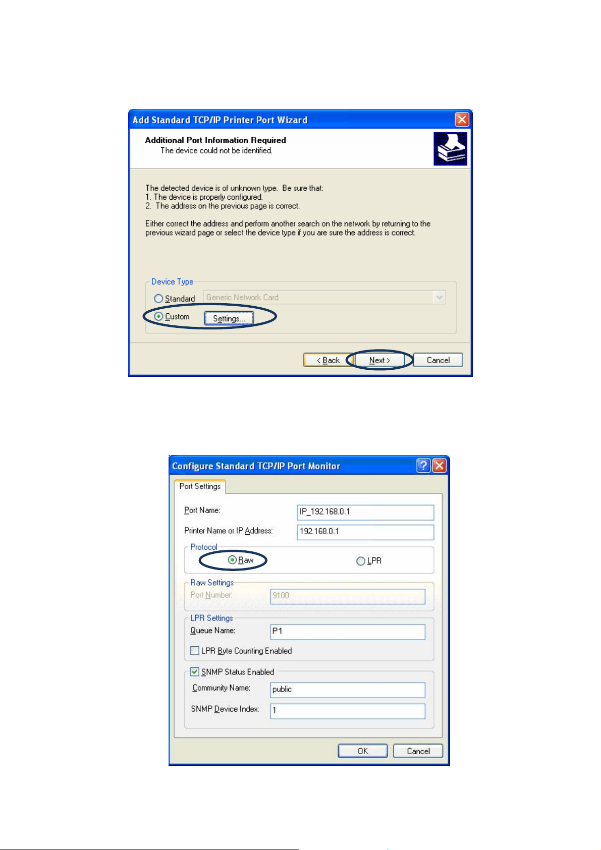
8. Select “Custom” and click “Settings”. When you have finished the settings at step 9, click
“Next” to continue.
9. Select “RAW” and then click “OK”.
63
Page 69

10. Click “Finish”.
11. Select a suitable printer manufacturer and the printer model and click “Next”. If your
printer is not in the list, click “Have Disk…” to install the driver of the printer. After
installation, the printer model will be added to the list.
64
Page 70

12. Choose to set the print whether as a default printer or not. Click “Next”.
13. Please select the test page will printed after the configuration or not. Please click “Next”.
65
Page 71

14. You have added the network printer to the PC successfully. The information of the printer
is displayed in the windows. Click “Finish”.
66
Page 72

10. IPP Printing
10.1 Introduction
IPP (Internet Printing Protocol) Printing provides a convenient way of remote printing service
by TCP/IP. When the MFP Server is work with a legal IP address, it can support IPP printing
in Windows 2000/XP/2003 by default. By using the IPP printing, you can share the printer to
all the PC’s that can access the MFP Server by IP. You can even share your MFP or printer to
Internet users.
10.2 System Setup
10.2.1 MFP Server Side
It is needless to do any setting on the MFP Server side. Make sure the MFP Server has
correct IP settings. If you want to share the printers to Internet users, you have to set a real IP
to the MFP Server. You also have to make sure that any gateway, router or firewall does not
block IPP protocol if you have these gateway devices installed in your network.
10.2.2 Client Side
You only need to perform Window’s standard Add New Printer procedure.
1. Click “Start”, choose “Settings” and select “Printers and Faxes”.
2. Click “Add a Printer”.
3. The “Add Printer Wizard ” is displayed. Click “Next”.
67
Page 73

4. Select “A network printer, or a printer attached to another computer”. Click “Next”.
5. Select “Connect to a printer on the Internet or on a home or office network” and enter the
URL of MFP Server. The URL format is “http://IP:631/Port Name”. The IP should be the
MFP Server’s IP. The number 631 is IPP standard port number. Port Name is the port
name of MFP Server that your printer is connected to. The default port name is “lpt1”.
One example of the URL is http://192.168.0.1:631/lpt1. After entering the URL of MFP
Server, click “Next”.
68
Page 74

6. Select a suitable printer manufacturer and the printer model and click “Next”. If your
printer is not in the list, click “Have Disk…” to install the driver of the printer. After
installation, the printer model will be added to the list.
7. Choose to set the print whether as a default printer or not. Click “Next”.
69
Page 75

8. You have added the network printer to the PC successfully. The information of the printer
is displayed in the windows. Click “Finish”.
70
Page 76

11. UNIX System Network
11.1 Introduction
The MFP Server is available for TCP/IP printing by Unix LPD (Line Printer Daemon) protocol.
The LPD protocol originated with Unix release is based on the BSD version of Unix and
supported under most versions of Unix.
This chapter explains how to configure the MFP Server for TCP/IP operation, and how to
modify configuration files on your Unix system to allow printing to the MFP Server. The
configuration examples in this manual follow the syntax for BSD based Unix systems. Please
refer to the related system documentation for the correct syntax of your systems.
To configure the MFP Server for LPD printing, perform the procedures below:
1. Enable MFP Server’s TCP/IP Support.
2. Set up MFP Server’s IP address.
3. Verify MFP Server’s IP Address.
4. Configure remote LPD printing on the host.
5. Print a test page.
In the next sections, we will describe these five procedures step by step.
11.2 Enable MFP Server ’s TCP/IP Support
The default configuration of the MFP Server is with TCP/IP support enabled. Anyway, you can
configure the MFP Server to enable TCP/IP support using the configuration program.
11.3 Setup MFP Server ’s IP Address
The MFP Server must have a unique IP address in order to be recognized by the netwo rk.
You can set up the IP address on the various Unix systems using any one of the following
methods:
1. DHCP (Dynamic Host Configuration Protocol)
2. BOOTP (Bootstrap Protocol)
The MFP Server will use the last two methods to obtain its IP address automatically if its IP
address is configured as Auto (0.0.0.0).
71
Page 77

11.3.1 DHCP
There are many Unix systems that support DHCP protocol, and the procedures to configure
the DHCP server database are different. Please refer to the manual of Unix for the way to use
different DHCP Server. It is highly recommended that the DHCP server should be located on
the same network as the MFP Server.
11.3.2 BOOTP
If you have the BOOTP daemon, bootpd, running on your UNIX system that is accessible by
the MFP Server, you can use the BOOTP protocol to set up the IP addre ss of the MFP Server.
We recommend that the BOOTP server should be located on the same subnet as the MFP
Server. If you use Network Information Services (NIS) in your system, you may need to
rebuild the NIS map with the BOOTP services before doing the following BOOTP
configuration. To rebuild the NIS map, please refer to your system documentation.
To configure the IP address data for the BOOTP server, you will need to log in the host of
BOOTP server as the superuser (root). Perform the f ollowing steps to add address entries,
1. Optionally, assign a name corresponding to the MFP Server’s IP address. Yo u can add
this address to the /etc/hosts file, by adding a line such as:
203.66.191.12 pserver
2. Add an entry to the host’s /etc/bootptab file, similar to the following:
hostname:\
:ht=1:\
:ha=MFP_Server_ethernet_address:\
:ip=MFP_Server_ip_address:
Lines should be indented with tabs.
Where hostname is the device name of a MFP Server, the ht=1 tag specifies the
hardware type is Ethernet, the ha= tag specifies the Ethernet address of a MFP Server,
which is the Node ID located on the MFP Server. The ha tag must be preceded by the ht
tag. The ip= tag should correspond to the IP address you want to assign to the MFP
Server.
For example, a MFP Server with the following configuration:
72
Page 78

Node ID: 00304F010101 (this implies Ethernet address is 00304F010101),
IP address: 203.66.191.12
The entry for this MFP Server in the /etc/bootptab file should be:
MF010101:\
:ht=1:\
:ha=00304F010101:\
:ip=203.66.191.12:
11.4 Verify MFP Server’s IP Address
To verify your MFP Server is responding to the newly assigned IP address using a PING
command:
ping ip-address
11.5 Configure Remote LPD Printing on the Host
The procedure you use to configure your Unix host(s) to allow printing to your network remote
MFP Server varies between different varieties of Unix. The procedure below can be used for
Unix variants that are related to BSD Unix, such as SunOS or Linux. For other versions of
Unix, consult your system documentation, keeping in mind that:
1. The MFP Server should be treated as a BSD networked MFP Server host.
2. The host name should be the name (or IP address) that you have assigned to the MFP
Server.
3. The printer name (or queue name) on the remote host should be lpt1, lpt2 or lpt3, the
name of the printer port on the MFP Server.
You will need to perform the tasks below, logged in as the superuser (root). To configure
your Unix host for printing,
1. Optionally, assign a name corresponding to the MFP Server’s IP address. You can add
this address to the /etc/hosts file, by adding a line such as:
203.66.191.186 pserver
73
Page 79

2. Create a spool directory for the printer in the same directory where spool directories are
normally kept on the machine, such as /var/spool or /var/spool/lpd:
mkdir /var/spool/lpd/pserv erd
chown daemon /var/spool/lpd/pserverd
chgrp daemon /var/spool/lpd/pserverd
chmod 775 /var/spool/lpd/pserverd
3. Add an entry to the host’s /etc/printcap file, similar to the following:
printer-name:\
:lp=:\
:rm=203.66.191.186:\
:rp=lpt1:\
:lf=/var/spool/lpd/pserverd.log:\
:sd=/var/spool/lpd/pserverd:\
:mx#0:
Lines should be indented with tabs. More than one printer name can be used, with
variants separated by vertical bars (name1|name2).
The rm= entry should correspond to the IP address you have assigned to the MFP Server.
You can also use a host name if you have assigned one in the /etc/hosts file.
The sd= entry should correspond to the spool directory you created in the previous step.
The rp= entry should correspond to the port name of the remote printer. The values
should be one of lpt1, lpt2 or lpt3 depends on the printer port.
The MFP Server should now be available for printing from your Unix host.
74
Page 80

12. MFP Server Installation in MAC OS
LPR Printing (Line Printer Remote technology) allows Macintosh computers to connect to
MFPs or printers via TCP/IP. LPR Printing can be set up on any Macintosh with version 9.x
above.
To enable LPR Printing in Macintosh, please follow the procedures below.
1. In the Desktop, click “System Preferences”.
2. Click “Print & Fax”.
75
Page 81

3. From the “Print & Fax” screen, click “Se t Up Printers…”.
4. Click “Add” to add the new MFP Server through TCP/IP.
76
Page 82

5. Enter the “Printer Type”, “Printer Address” and “Queue Name” and select the “Printer
Model” to setup the MFP Server. Click “Add” to continue.
Printer Type: LPD/LPR
Printer Address: Input the IP Address of the MFP Server
Queue Name: The queue name of the MFP Server is “lpt1”.
Printer Model: Select the MFP or Printer Model that is attached to the MFP Server.
77
Page 83

6. The MFP Server is installed completely. You can see it in the “Printer List”.
7. You can print a file to check whether the MFP Server is installed successfully.
78
Page 84

13. Troubleshooting
1. This product is not found even after searching by the “MFP Server Control Manager”.
Check if the power adapter and the network cable are connected to the MFP Server
properly.
Check if the LAN and Ready LEDs are turned on.
Check if the IP Address of the MFP Server is in the network segment as your
computer.
- If you are not sure the IP Address setting of the MFP Server, please check the
TCP/IP setting of the MFP Server from the “Server Manager”.
2. The ways to change the IP Address of the MFP Server.
A DHCP Serv er is installed in the network
If a DHCP Server is installed, you can setup to let the MFP Server get IP Address from
the DHCP Server automatically.
1. Open “Server Manager” and then select “TCP/IP” setting.
2. Select “Auto IP” and click “Save”.
3. Reboot the MFP Server.
Set up the IP Address Manually
1. Open “Server Manager” and then select “TCP/IP” setting.
2. Select “Static IP” and enter the IP Address and Subnet Mask as your computer.
Click “Save”.
3. Reboot the MFP Server.
NOTE: Set a static IP Address to MFP Server is recommended since DHCP
assignment may dramatically change the IP Address for MFP Server.
79
Page 85

3. A user always connects the MFP Server.
Check the “Idle Timeout” setting of the MFP Server from the right side of “MFP Server
Control Manager”. If the status is “Never Timeout”, please contact with your
administrator to change the setting.
Contact with the current user and ask the user to disconnect the device.
If the user forgets to disconnect the device, you can inform the administrator to release
the device.
4. I can’t use the MFP to scan, print or read the card reader even I have followed the
installation of MFP as the manual.
Check if the MFP you are using is in the “Compatibility List” in Appendix.
Attached the MFP to PC directly and try if the MFP is able to use.
80
Page 86

Appendix A: MFP Server Compatibility List
The compatibility information is the first released in December 2007. For the latest information,
please contact with your dealer.
Windows 2000 & XP Windows Vista 32/64
No. Brand Name MFP Model
Print Scan Fax
1. HP CM1015MFP 3 3 N/A N/A
2. HP Desk Jet 895cxi 3 N/A N/A N/A 3 N/A N/A N/A
3. HP Desk Jet 970cxi 3 N/A N/A N/A 3 N/A N/A N/A
4. HP Desk Jet D2460 3 N/A N/A N/A 3 N/A N/A N/A
5. HP Desk Jet F2180 3 N/A N/A 3 N/A N/A
6. HP Desk Jet F380 3 3 N/A N/A 3 3 N/A N/A
7. HP Laser Jet 1000 (GDI) 3 N/A N/A N/A
8. HP Laser Jet 1010 (GDI) 3 N/A N/A N/A
9. HP Laser Jet 1018 3 N/A N/A N/A *3 N/A N/A N/A
10. HP Laser Jet 1020 (GDI) 3 N/A N/A N/A
11. HP Laser Jet 1022 (GDI) 3 N/A N/A N/A 3 N/A N/A N/A
12. HP Laser Jet 3000dn 3 N/A N/A N/A 3 N/A N/A N/A
13. HP Laser Jet 3015 3 3 3 N/A
14. HP Laser Jet 3020 3 N/A 3 N/A
15. HP Laser Jet 3030 3 3 3 N/A
16. HP Laser Jet 3050 3 3 N/A
17. HP Laser Jet 3052 3 3 N/A N/A
18. HP Laser Jet 3055 3 3 N/A
19. HP Laser Jet 3380 3 3 3 N/A
20. HP Laser Jet 3390 3 3 N/A
21. HP Laser Jet 3392 3 3 N/A
22. HP Laser Jet M1005MFP 3 3 N/A N/A 3 3* N/A N/A
23. HP PSC 750 3 3 N/A N/A
24. HP PSC 1210 3 3 N/A N/A 3 N/A N/A
25. HP PSC 1315 3 N/A N/A N/A 3 N/A N/A N/A
26. HP PSC 1350 3 3 N/A N/A
27. HP PSC 1410 3 3 N/A N/A 3 3 N/A N/A
28. HP PSC 1510 3 3 N/A N/A 3 N/A N/A
29. HP PSC 1610 3 3 N/A 3 3 N/A 3
30. HP PSC 2210 3 3 3
31. HP PSC 2310 3 3 N/A 3
32. HP PSC 2355 3 3 N/A 3 3 N/A 3
33. HP PSC 2410 3 3 N/A 3
Card
Reader
Print Scan Fax
Card
Reader
81
Page 87

Windows 2000 & XP Windows Vista 32/64
No. Brand Name MFP Model
Print Scan Fax
Card
Reader
Print Scan Fax
Card
Reader
34. HP PSC 2510 3 3 N/A 3
35. HP Photosmart 2575 3 3 N/A 3 3 N/A 3
36. HP Photosmart 2610 3 3 3
37. HP Photosmart 2710 3 3 3
38. HP Photosmart 3110 3 3 3 3
39. HP Photosmart 3310 3 3 3
40. HP Photosmart 475 3 N/A N/A 3
41. HP Photosmart 7450 3 N/A N/A 3
42. HP Photosmart 7830 3 N/A N/A 3
43. HP Photosmart 8030 3 N/A N/A 3 3 N/A N/A 3
44. HP Photosmart 8230 3 N/A N/A 3 3 N/A N/A 3
45. HP Photosmart 8250 3 N/A N/A 3
46. HP Photosmart 8450 3 N/A N/A 3
47. HP Photosmart 8750 3 N/A N/A
48. HP Photosmart A526 3 N/A N/A 3 3 N/A N/A 3
49. HP Photosmart C3180 3 3 N/A 3 3 N/A 3
50. HP Photosmart C4180 3 3 N/A
51. HP Photosmart C4280 3 N/A 3 3 N/A 3
52. HP Photosmart C5180 3 N/A 3 3 N/A 3
53. HP Photosmart C5280 3 N/A 3 3 N/A 3
54. HP Photosmart C6180 3 3 N/A 3 3 N/A 3
55. HP Photosmart C6280 3 N/A 3 3 N/A 3
56. HP Photosmart C7180 3
57. HP Photosmart C7280 3
3 3
3 3
3
3
58. HP Photosmart D5160 3 N/A N/A 3 3 N/A N/A 3
59. HP Photosmart D7160 3 N/A N/A
60. HP Photosmart D7360 3 N/A N/A 3 3 N/A N/A 3
61. HP Office Jet 4255 3 3 N/A 3 N/A
62. HP Office Jet 4355 3 3 N/A
63. HP Office Jet 5510 3 3 N/A
64. HP Office Jet 5610 3 3 N/A 3 N/A
65. HP Office Jet 6110 3 3 N/A
66. HP Office Jet 6210 3 3 N/A
67. HP Office Jet 6310 3 N/A 3 3
68. HP Office Jet 7130 3
69. HP Office Jet 7210 3 3 3
70. HP Office Jet 7410 3 3 3 3 3
82
Page 88

Windows 2000 & XP Windows Vista 32/64
No. Brand Name MFP Model
Print Scan Fax
Card
Reader
Print Scan Fax
Card
Reader
71. HP Office Jet 9100 3 3 3
72. HP Office Jet 9100 3 3 3
73. HP Office Jet L7380 3 3 N/A 3 N/A
74. HP Office Jet L7580 3 3 3 3 3
75. HP Office Jet J5780 3 N/A 3 N/A
76. HP Office Jet Pro K5400dn 3 N/A N/A N/A 3 N/A N/A N/A
77. EPSON CX1500 3 3 N/A N/A
78. EPSON CX3700 3 3 N/A N/A
79. EPSON CX3900 3 3 N/A N/A 3 3 N/A N/A
80. EPSON CX4100 3 3 N/A N/A 3 3 N/A N/A
81. EPSON CX4700 3 3 N/A 3 3 3 N/A 3
82. EPSON CX5500 3 3 N/A N/A 3 3 N/A N/A
83. EPSON CX5900 3 3 N/A 3 3 3 N/A 3
84. EPSON CX7300 3 3 N/A 3 3 3 N/A 3
85. EPSON CX8300 3 3 N/A 3 3 3 N/A 3
86. EPSON CX9300F 3 3 N/A 3 3 3 N/A 3
87. EPSON CX9400F 3 3 N/A 3 3 3 N/A 3
88. EPSON EPL-6200L (GDI) 3 N/A N/A N/A
89. EPSON EPL-6200 3 N/A N/A N/A *3 N/A N/A N/A
90. EPSON EPL-5900L 3 N/A N/A N/A *3 N/A N/A N/A
91. EPSON LQ-300+II 3 N/A N/A N/A *3 N/A N/A N/A
92. EPSON PHOTO 4990 Scanner N/A 3 N/A N/A
93. EPSON R310 3 N/A N/A
94. EPSON R340 3 N/A N/A 3
95. EPSON R350 3 N/A N/A 3
96. EPSON RX430 3 3 N/A 3
97. EPSON RX510 3 3 N/A 3
98. EPSON RX520 3 3 N/A 3
99. EPSON RX530 3 3 N/A 3 3 3 N/A 3
100. EPSON RX630 3 3 N/A 3
101. EPSON RX650 3 3 N/A 3 3 3 N/A 3
102. EPSON Stylus C1 10 3 N/A N/A N/A 3 N/A N/A N/A
103. EPSON Stylus C45 3 N/A N/A N/A 3 N/A N/A N/A
104. EPSON Stylus PHOTO1390 3 N/A N/A N/A 3 N/A N/A N/A
105. EPSON Stylus PHOTO750 3 N/A N/A N/A 3 N/A N/A N/A
106. EPSON Stylus PHOTO R270 3 N/A N/A N/A 3 N/A N/A N/A
107. EPSON Stylus PHOTO RX590 3 3 N/A 3 3 3 N/A 3
108. CANON FAXPHONE L120 3 N/A N/A
83
Page 89

Windows 2000 & XP Windows Vista 32/64
No. Brand Name MFP Model
109. CANON iP1200 3 N/A N/A N/A 3 N/A N/A N/A
110. CANON iP1880
111. CANON iP3300
112. CANON iP3500
113. CANON iP4300
114. CANON iP4500
115. CANON iX4000
116. CANON MPC 190 3 3 N/A N/A
117. CANON PIXMA MP110 3 3 N/A N/A
118. CANON PIXMA MP130 3 N/A 3 3 N/A 3
119. CANON PIXMA MP145 3 3 N/A N/A 3 3 N/A N/A
120. CANON PIXMA MP150 3 3 N/A N/A
121. CANON PIXMA MP160 3 3 N/A N/A
122. CANON PIXMA MP170 3 3 N/A 3
123. CANON PIXMA MP180 3 3 N/A
124. CANON PIXMA MP450 3 N/A 3 3 N/A 3
125. CANON PIXMA MP510 3 3 N/A
126. CANON PIXMA MP530 3 3 N/A
127. CANON PIXMA MP700 3 3 3
128. CANON PIXMA MP730 3 3 3
129. CANON PIXMA MP780 3 3 N/A
130. CANON PIXMA MP810 3 3 N/A
131. CANON PIXMA MX7000 3 3 3 3 3 3
132. CANON
133. LEXMARK
134. LEXMARK
135. LEXMARK X2350 3 3 N/A N/A
136. LEXMARK X3330 3 3 N/A N/A
137. LEXMARK X3350 3 3 N/A N/A
138. LEXMARK X3470 3 N/A
139. LEXMARK X4270 3 3 N/A
140. LEXMARK X5470 3 3
141. LEXMARK X5150 3 3 N/A N/A
142. LEXMARK X6150 3 3 3 N/A
143. LEXMARK X6170 3 3 3 N/A
Pro 9000
P4350
P6250
Print Scan Fax
3
3
3
3
3
3
3
3 3 N/A
3 N/A
N/A N/A N/A
N/A N/A N/A
N/A N/A N/A
N/A N/A N/A
N/A N/A N/A
N/A N/A N/A
N/A N/A
N/A
Card
Reader
3
Print Scan Fax
3
3
3
3
3
3
3
N/A N/A N/A
N/A N/A N/A
N/A N/A N/A
N/A N/A N/A
N/A N/A N/A
N/A N/A N/A
N/A N/A
N/A
Card
Reader
84
Page 90

Windows 2000 & XP Windows Vista 32/64
No. Brand Name MFP Model
Print Scan Fax
Card
Reader
Print Scan Fax
Card
Reader
144. LEXMARK X7170 3 3 N/A
145. LEXMARK X7350 3 3 N/A
146. LEXMARK Z617 (GDI) 3 N/A N/A N/A
147. LEXMARK Z735 (GDI) 3 N/A N/A N/A
148. Brother MFC-210C 3 3 3 3
149. Brother MFC-215C 3 3 3 3
150. Brother MFC-2820 3 N/A 3 N/A
151. Brother MFC-420CN 3 3 3 3
152. Brother MFC-425CN 3 3 3 3
153. Brother MFC-3240C 3 3 3 N/A
154. Brother MFC-7420 3 3 3 N/A
155. Brother MFC-7820N 3 3 3 N/A
156. Brother MFC-8840D 3 3 3 N/A
157. Konica Minolta 1380MF 3 3 N/A N/A
158. Konica Minolta 2480MF 3 3 N/A N/A *3 N/A N/A N/A
159. Samsung
SF-565P
3
3
3
N/A 3 3 3 N/A
160. Samsung SCX-4100 3 3 N/A N/A
161. Samsung SCX-4200 3 3 N/A N/A
162. Samsung SCX-4521F 3 3 N/A 3 3 N/A
163. Samsung SCX-4720F 3 3 3 N/A
164. Samsung SCX-5530FN 3 3 N/A
165. Dell 944 3 3 N/A 3
166. Dell MonoLaser MFP1 125 3 3 N/A 3 3 N/A
167. BenQ CM3000 3 3 N/A N/A
“N/A” means that the MFP doesn’t support the function.
“*” means that MFP only supports Vista 32.
85
 Loading...