

Page 1

Wired / Wireless / PoE
CMOS IP Camera
ICA-107
ICA-107W
ICA-107P
User’s Manual
Version: 1.00
Page 2

Copyright © 2007 by PLANET Technology Corp. All rights reserved. No part of this publication may
be reproduced, transmitted, transcribed, stored in a retrieval system, or translated into any language
or computer language, in any form or by any means, electronic, mechanical, magnetic, optical,
chemical, manual or otherwise, without the prior written permission of PLANET.
PLANET makes no representations or warranties, either expressed or implied, with respect to the
contents hereof and specifically disclaims any warranties, merchantability or fitness for any particular
purpose. Any software described in this manual is sold or licensed "as is". Should the programs prove
defective following their purchase, the buyer (and not PLANET, its distributor, or its dealer) assumes
the entire cost of all necessary servicing, repair, and any incidental or consequential damages
resulting from any defect in the software. Further, PLANET reserves the right to revise this publication
and to make changes from time to time in the contents hereof without obligation to notify any person
of such revision or changes.
All brand and product names mention ed in this manual are trademarks and/or registered tr ademarks of their
respective holders.
Federal Communication Commission Interference Statement
This equipment has been tested and found to comply with the limits for a Class B digital device,
pursuant to Part 15 of FCC Rules. These limits are designed to provide reasonable protection against
harmful interference in a residential installation. This equipment generates, uses, and can radiate
radio frequency energy and, if not installed and used in accordance with the instructions, may cause
harmful interference to radio communications. However, there is no guarantee that interference will
not occur in a particular installation. If this equipment does cause harmful interference to radio or
television reception, which can be determined by turning the equipment off and on, the user is
encouraged to try to correct the interference by one or more of the following measures:
1. Reorient or relocate the receiving antenna.
2. Increase the separation between the equipment and receiver.
3. Connect the equipment into an outlet on a circuit different from that to which the receiver is
connected
4. Consult the dealer or an experienced radio technician for help
FCC Caution
To assure continued compliance. (example-use only shielded interface cables when connecting to
computer or peripheral devices). Any changes or modifications not expressly approved by the party
responsible for compliance could void the user’s authority to operate the equipment.
This device complies with Part 15 of the FCC Rules. Operation is subject to the Following two
conditions: ( 1 ) This device may not cause harmful interference, and ( 2 ) this Device must accept
any interference received, including interference that may cause undesired operation.
Federal Communication Commission (FCC) Radiation Exposure Statement
This equipment complies with FCC radiation exposure set forth for an uncontrolled environment. In
order to avoid the possibility of exceeding the FCC radio frequency exposure limits, human proximity
to the antenna shall not be less than 20 cm (8 inches) during normal operation.
Page 3

R&TTE Compliance Statement
This equipment complies with all the requirements of DIRECTIVE 1999/5/CE OF THE EUROPEAN PARLIAMENT AND
THE COUNCIL OF 9 March 1999 on radio equipment and telecommunication terminal Equipment and the mutual
recognition of their conformity (R&TTE)
The R&TTE Directive repeals and replaces in the directive 98/13/EEC (Telecommunications Terminal Equipment and
Satellite Earth Station Equipment) As of April 8,2000.
Safety
This equipment is designed with the utmost care for the safety of those who install and use it.
However, special attention must be paid to the dangers of electric shock and static electricity when
working with electrical equipment. All guidelines of this and of the computer manufacture must
therefore be allowed at all times to ensure the safe use of the equipment
.
CE Mark Warning
This is a Class A product. In a domestic environment, this product may cause radio interference, in
which case the user may be required to take adequate measures.
WEEE Regulation
To avoid the potential effects on the environment and human health as a result of the
presence of hazardous substances in electrical and electronic equipment, end users of
electrical and electronic equipment should understand the meaning of the crossed-out
wheeled bin symbol. Do not dispose of WEEE as unsorted municipal waste and have
to collect such WEEE separately.
Revision
User’s Manual for PLANET Wired / Wireless / PoE CMOS IP Camera
Model: ICA-107 / ICA-107W / ICA-107P
Rev: 1.0 (July. 2007)
Part No. EM-ICA-107_W_P
Page 4

Contents
1. Introduction.......................................................................................................... 1
2. Package Content................................................................................................. 2
3. System Requirement........................................................................................... 3
4. Hardware Installation........................................................................................... 4
4.1. LED and Focusing .....................................................................................................4
4.2. Hardware Connection................................................................................................5
Installation Procedure .......................................................................................................6
5. Software Installation ............................................................................................ 7
6. Using the IP Camera Admin .............................................................................. 13
6.1. General Setting........................................................................................................ 14
6.2. Detail Setting ...........................................................................................................16
6.2.1. Network Setting ...........................................................................................17
6.2.2. Wireless Settings (ICA-107W Only).............................................................18
6.2.3. E-Mail Setting ..............................................................................................21
6.2.4. PPPoE Settings ...........................................................................................22
6.2.5. FTP Settings ................................................................................................23
6.2.6. Date / Time Settings ....................................................................................24
6.2.7. Resolution....................................................................................................25
6.2.8. Advanced Setting.........................................................................................26
6.2.9. Users ...........................................................................................................27
6.2.10. Tools ............................................................................................................ 28
6.2.11. About ...........................................................................................................29
6.3. Setting Wizard .........................................................................................................30
7. Using the Camera Viewer.................................................................................. 32
7.1. Introduction to the Control Panel .............................................................................33
7.2. Camera Buttons.......................................................................................................34
7.3. Camera Status.........................................................................................................35
7.4. Control Buttons........................................................................................................35
7.5. Video Recording ......................................................................................................37
7.6. Change Resolution ..................................................................................................38
7.7. View Four Cameras Simultaneously........................................................................39
7.8. Viewer Utility Setting................................................................................................40
7.8.1. Setting..........................................................................................................41
7.8.2. Recording ....................................................................................................42
Page 5

7.8.3. Status...........................................................................................................44
7.8.4. General ........................................................................................................46
7.8.5. About ...........................................................................................................47
7.9. Playback ..................................................................................................................48
7.10.Rotate Video ...........................................................................................................51
8. Web Connection and Setup............................................................................... 52
8.1. Camera Setting........................................................................................................55
8.2. LAN Setting .............................................................................................................57
8.3. WLAN (ICA-107W Only) ..........................................................................................59
8.4. E-Mail and FTP........................................................................................................61
8.5. Motion Detection...................................................................................................... 63
8.6. System..................................................................................................................... 64
8.7. Status.......................................................................................................................66
8.8. Users .......................................................................................................................67
8.9. Log...........................................................................................................................68
9. Technical Specifications .................................................................................... 69
10. Appendix A Router/Gateway Setup for Internet Viewing ................................... 70
11. Appendix B Viewing via UPnP in Windows XP.................................................. 72
12. Appendix D Configure Windows 2003 Server ................................................... 77
Page 6

1. Introduction
Searching for a powerful and economical Internet Camera? PLANET is glad to introduce
our ICA-107 / ICA-107W / ICA-107P. Those Internet Cameras Integrated a microcomputer
and a high quality CMOS digital-Image-Sensor, enabling it to display high quality live
streaming video over your LAN and the Internet.
The motion detection of the ICA-107 series can notify users via email or ftp when
detecting any movement. With its admin software, no expertise required, your first
surveillance network can be easily, efficiently established in few minutes.
ICA-107W support 802.11b/g wireless network, that will save your time and cost for wiring.
And ICA-107P has provided IEEE802.3af standard PoE interface, it helps you to locate the
camera to any location that is no power outlet. With the Windows based utility, IP Camera
Viewer, the ICA-107 series could take a snapshot, record and playback the video files. Also
with a powerful central manage system – Cam Viewer Lite, it can help you to manage all the
PLANET internet cameras in the same software, not just ICA-107 serial.
In the following section, unless specified, the term “IP Camera” will mean all the cameras
above. For Cam Viewer Lite, you may check the manual in Cam Viewer Lite CD disk for the
details.
1
Page 7

2. Package Content
Internet Camera
Power Adapter
Camera Stand Kit
Category 5 Ethernet Cable
Quick Installation Guide
CD-Rom
External Antenna (ICA-107W only)
If any of the above items are missing, please contact your supplier.
2
Page 8

3. System Requirement
Model
Network Environment
Network Access
Additional Interface
Monitoring System Recommendation
System Hardware
Web Browser
System Requirement for IP Camera Admin & Viewer
Support OS
System Hardware
ICA-107 ICA-107W ICA-107P
10/ 100Base-TX Ethernet
- IEEE 802.11b/g IEEE 802.3af PoE
• CPU: Pentium 4, 1.6GHz or above
• Memory Size: 256 MB (512 MB Recommended)
• VGA card resolution: 800 x 600 or above
• Internet Explorer 6.0 or above
Windows 2000 SP4, Windows XP SP2
1 – 4 cameras surveillance application
• CPU: Pentium 4, 2.0GHz or above
• Memory Size: 256 MB or above.
• VGA card resolution: 1024x768 or above
3
Page 9
4. Hardware Installation
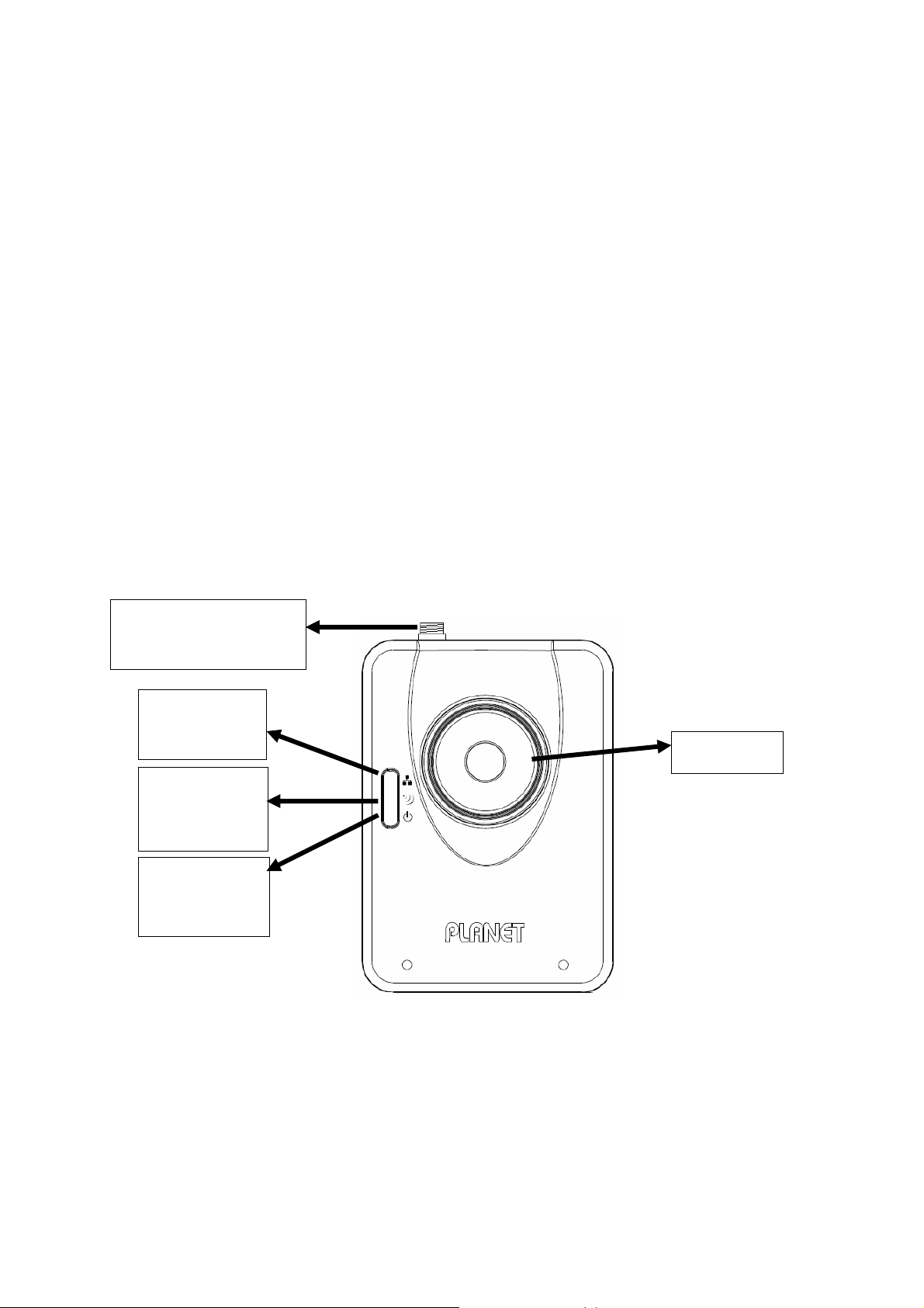
4.1. LED and Focusing
The IP Camera head and its focus ring allow you to modify the aim and focus of the IP
Camera. To adjust the IP Camera’s focus, please rotate the focus ring.
There are LEDs indicating the IP Camera status and networking status.
y Power
When the IP Camera is power on, the LED will light on.
y WLAN (ICA-107W only)
When the IP Camera is linking with wireless interface, the LED will light on. This LED will
flash when video is transmitting or receiving.
y LAN
When the IP Camera is linking to wired interface, the LED will light on. This LED will flash
when video is transmitting or receiving.
Antenna Connector
(ICA-107W only)
LAN LED: LAN
Activity
Focus Ring
Wireless LED :
WLAN Activity
Power LED:
Power On
Front view of IP Camera
(Example on ICA-107W )
4
Page 10
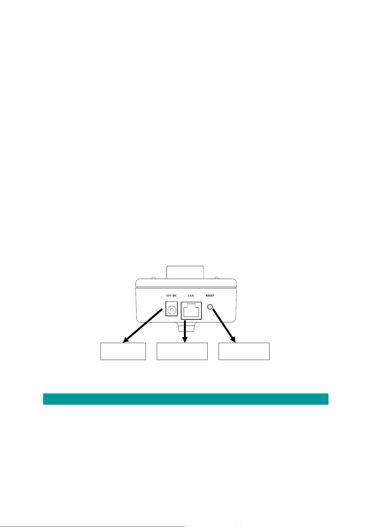
4.2. Hardware Connection
y Power Input
The DC power input connector is located on the IP Camera's bottom panel, and is
labeled 12V DC with a single jack socket to supply power to the IP Camera. Power will
be generated when the power supply is connected to a wall outlet.
y Ethernet Jack
The IP Camera's bottom panel features an RJ-45 connector for connections to
10Base-T Ethernet cabling or 100Base-TX Fast Ethernet cabling (which should be
Category 5 twisted-pair cable). The port supports “Auto-MDIX” function, allowing the
IP Camera to automatically detect or negotiate the transmission speed of the network.
For ICA-107P, this port is also the PoE interface.
y Antenna Connector (ICA-107W only)
ICA-107W provides a standard Reverse SMA connector on its top panel. The external
antenna allows you to adjust its position to obtain the maximum signal.
y Reset Button
1. Press the reset button (for less than 2 seconds) and the IP Camera will reboot.
2. Press the reset button for more than 5 seconds and the IP Camera will reset to the
factory default. The factory default settings are listed in the table below.
Ethernet Jack Power Input Reset Button
Bottom View of IP Camera
(Example on ICA-107)
Factory Default Setting
IP Address 192.168.0.20
Default Account Admin
Default Password Admin
Default Http Port 80
Default Video Port 4321
5
Page 11

Installation Procedure
1. Unpack the package and verify that all the items listed in the Chapter 2 are available.
2. Connect the IP Camera to your network with the attached network cable; please connect
the IP camera to your network switch or router.
3. Connect the power adapter to IP Camera and plug the power adapter to power outlet. The
IP Camera will be powered on. When the IP Camera is ready, the Power LED will light on.
4. Make sure that you have installed the ActiveX utility.
Note: It is highly recommended to use the power adapter shipped with the IP Camera, do
NOT use any other power adapter from other sources. It may make the IP Camera damage.
6
Page 12
5. Software Installation
Follow the steps below to install the utilities. The following installation is implemented in
Windows XP and the installation procedure is similar to Windows 2000.
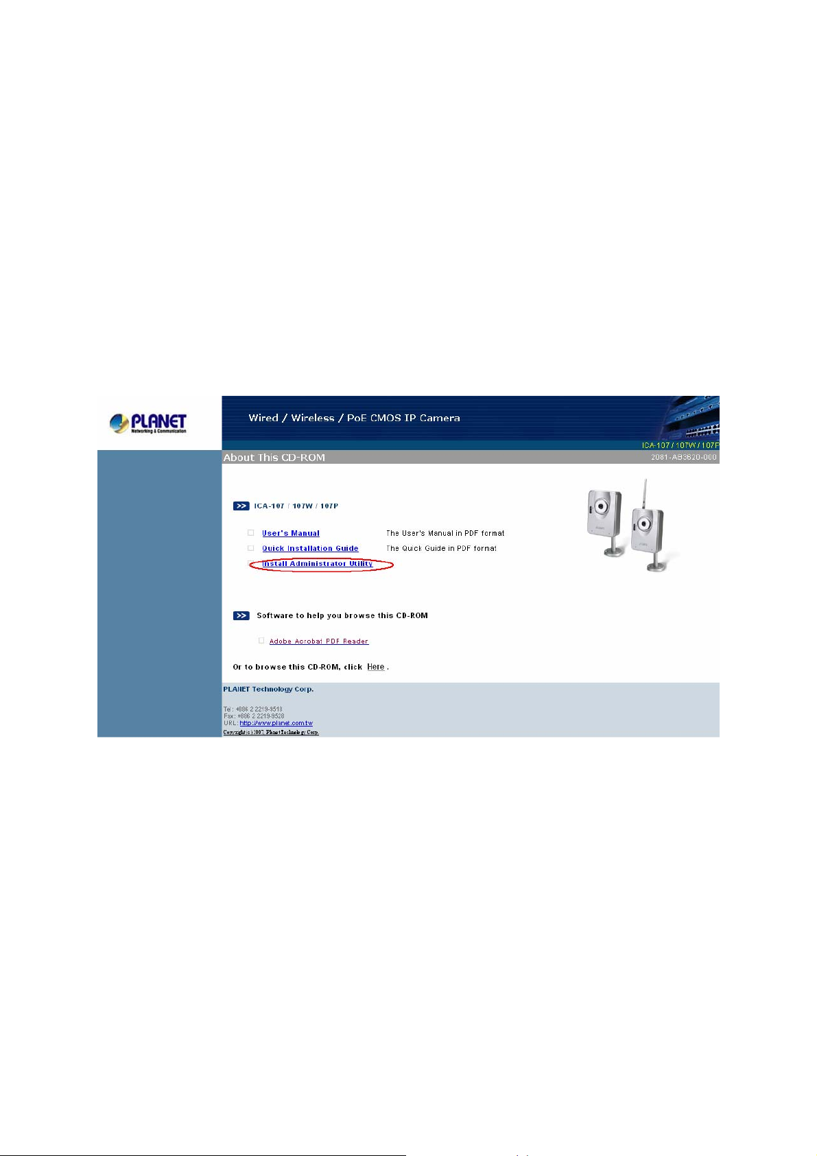
1. Insert the CD shipped along with the IP Camera into your CD-ROM drive. The installation
page should open with your default browser. If not, please double click on the
“default.htm” in the CD.
2. Click on the hyperlink “Install Administrator Utility”.
7
Page 13
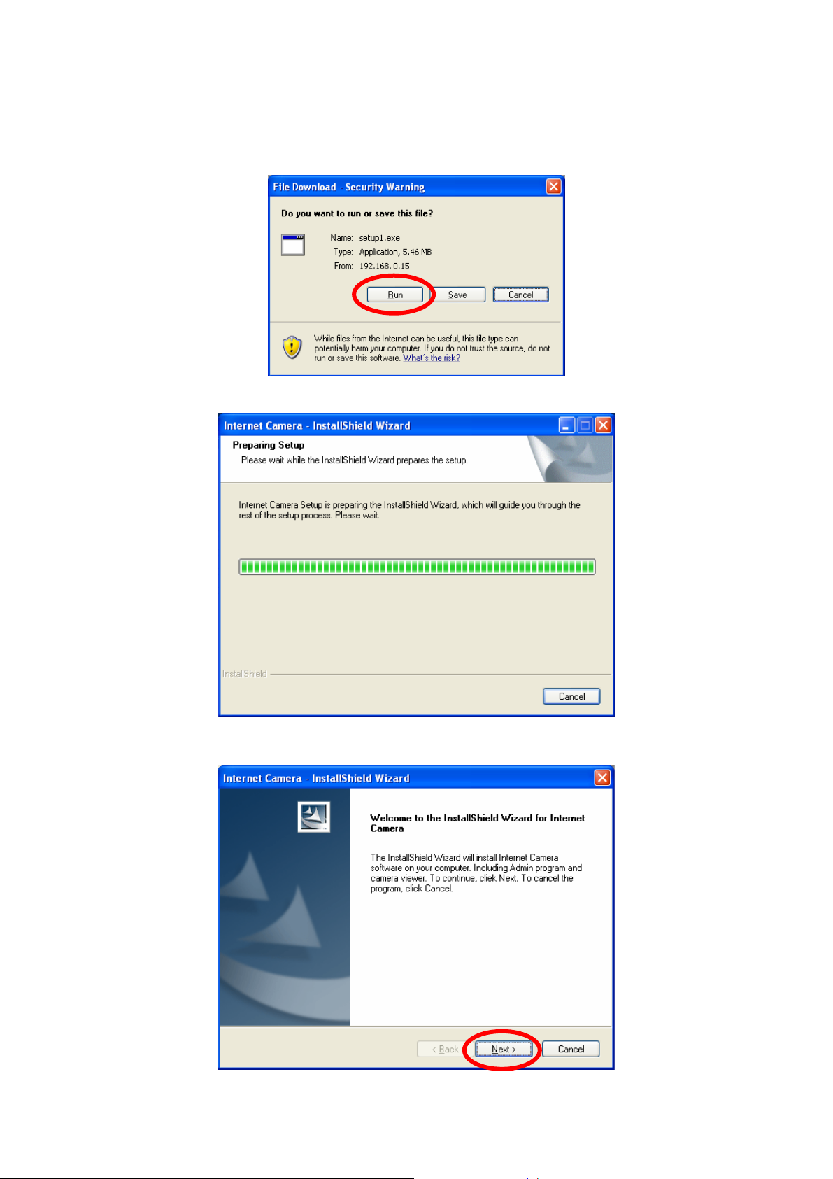
3. After clicking on the “Install Administrator Utility” hyperlink, the browser should prompt to
download the installation program. Click on the “Run” button, the installation program
should be started.
4. Click “Next” to start the installation.
8
Page 14
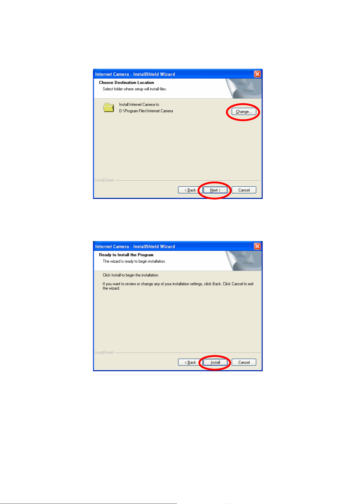
5. Click on the “Change” button to choose the destination you wished to install the utility. If
no specific requirement, leave the default setting and click “Next”.
6. Click “Install” to start installing the utility.
9
Page 15
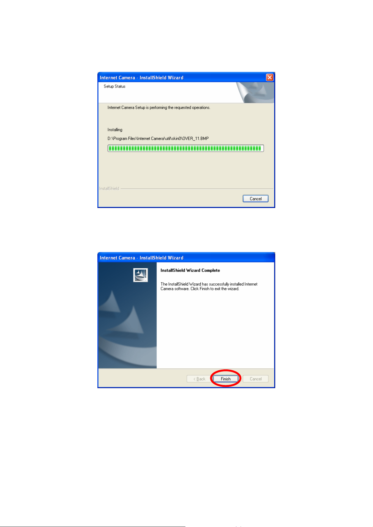
7. The system will install the program automatically.
8. Click “Finish” to complete the software installation.
10
Page 16
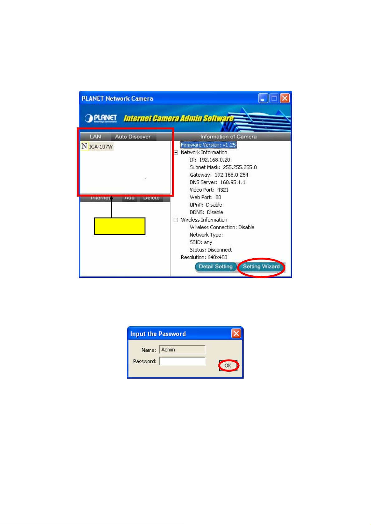
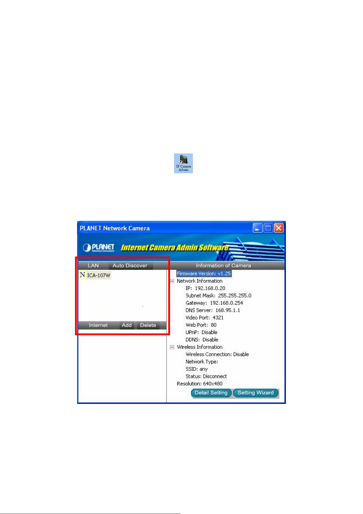
9. After the installation, IP Camera Admin will launch automatically. It will start to search the
IP Cameras in your intranet and it will list all the available IP Cameras on the camera list.
Choose the one that you would like to configure and click “Setting Wizard” to processed.
Camera list
10. Please enter the default password “Admin” and click “OK” to login to the IP Camera’s
setup page.
11
Page 17
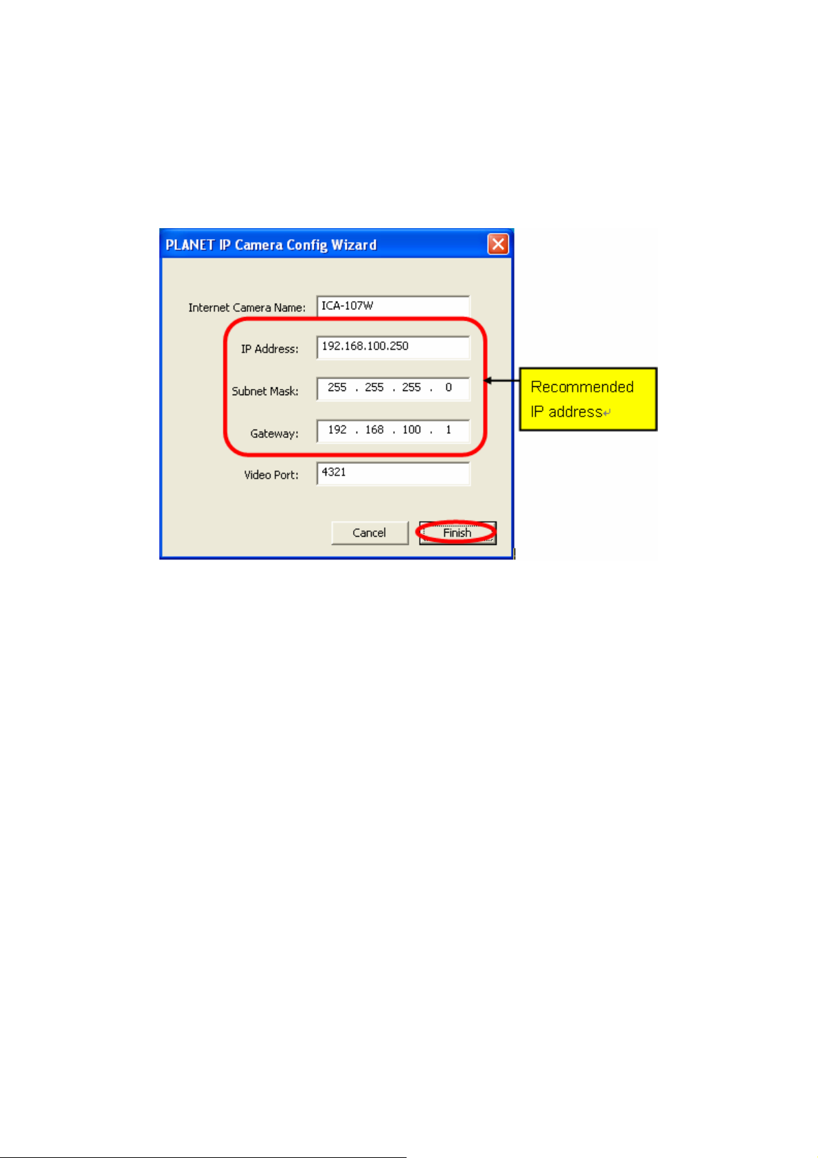
11. To let the IP Camera work, you should configure the IP Camera’s IP address as you want.
The utility will try to find an available IP address and recommend you using that address.
Besides work with the recommended IP, you may input the IP address manually. Please
be aware that the IP address of the IP Camera must be in the same IP segment of your .
Click “Finish” to apply the configuration.
12. After press “Finish”, the camera will restart. Please wait for a minute. Then you may refer
to next section to start the configure utility and setup your IP camera.
12
Page 18
6. Using the IP Camera Admin
The IP Camera Admin allows users to search and setup the cameras located within the
Intranet. With the IP Camera Admin, users can view all the information about the selected IP
Camera; furthermore, it provides a setting wizard, which can guide users to add the IP
Camera to the network easily and promptly.
There are two ways to run the IP Camera Admin:
1. Click “Start”, select “Programs”→“IP Camera” →”Admin Utility” to run the utility.
2. Double click the IP Camera Admin icon (
Once the utility is started, it will search the available IP Cameras in your intranet. For further
configurations, please refer to the following sections.
) on the desktop to run the utility.
13
Page 19
6.1. General Setting
LAN
Auto Discover The IP Camera Admin will search all the available IP Camera
within the network when you click on this button.
Camera List The name and setting status of the IP Camera will show in this
list.
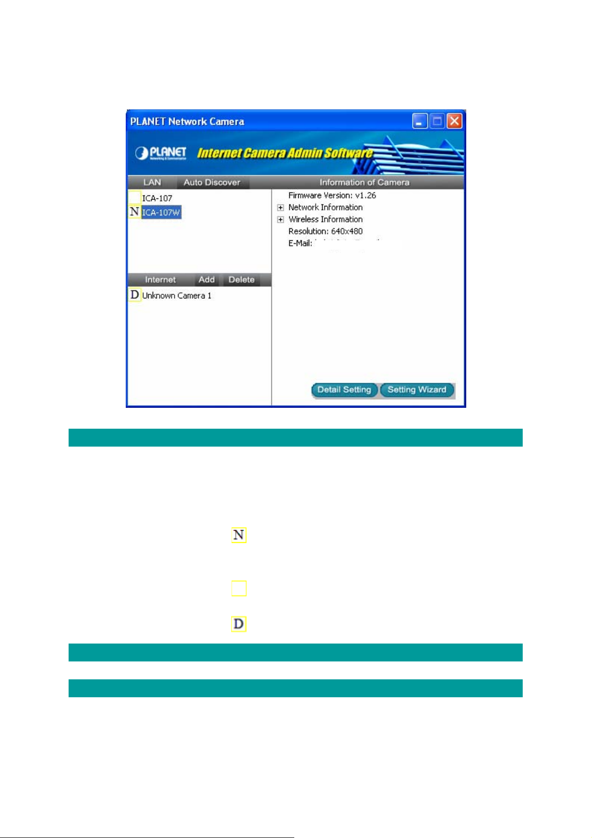
The “
status of factory default.
The “
The “
Internet
Add and Delete Button The functions located in this area are reserved for future use.
Information of Camera
” icon means the configuration of the IP Camera is in the
” icon means the IP Camera has been configured before.
” icon means the camera is unknown.
Camera Information
All information about the selected IP Camera will display here.
The informat
Address, UPnP Setting, DDNS Setting, Resolution and E-mail
IP
ion includes Firmware Version, Network Information,
14
Page 20

Camera Setting
etting, etc.
s
Detail Setting ight use this function for further configuring the IP Camera,
You m
such as IP address, Resolution, password and firmware upgrad
e,
etc.
etting Wizard You might use this function to configure the camera name, IP
S
address and the video port of the IP Camera.
15
Page 21
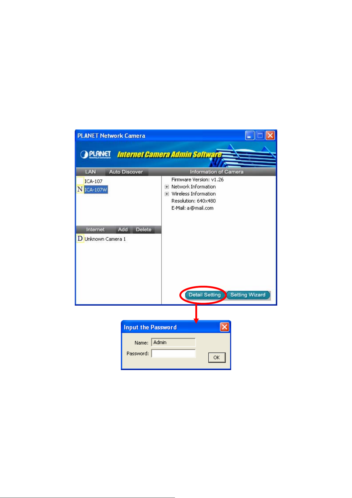
6.2. Detail Setting
After clicking on the “Detail Setting”, the IP Camera Admin will ask you to enter the
“Administrator Name” and “Password” for authentication. The default administrator name /
password are:
Administrator Name: “Admin”
Password: “Admin”
After entering the password and clicking on the “OK” button, you could start to configure your
IP Camera.
16
Page 22
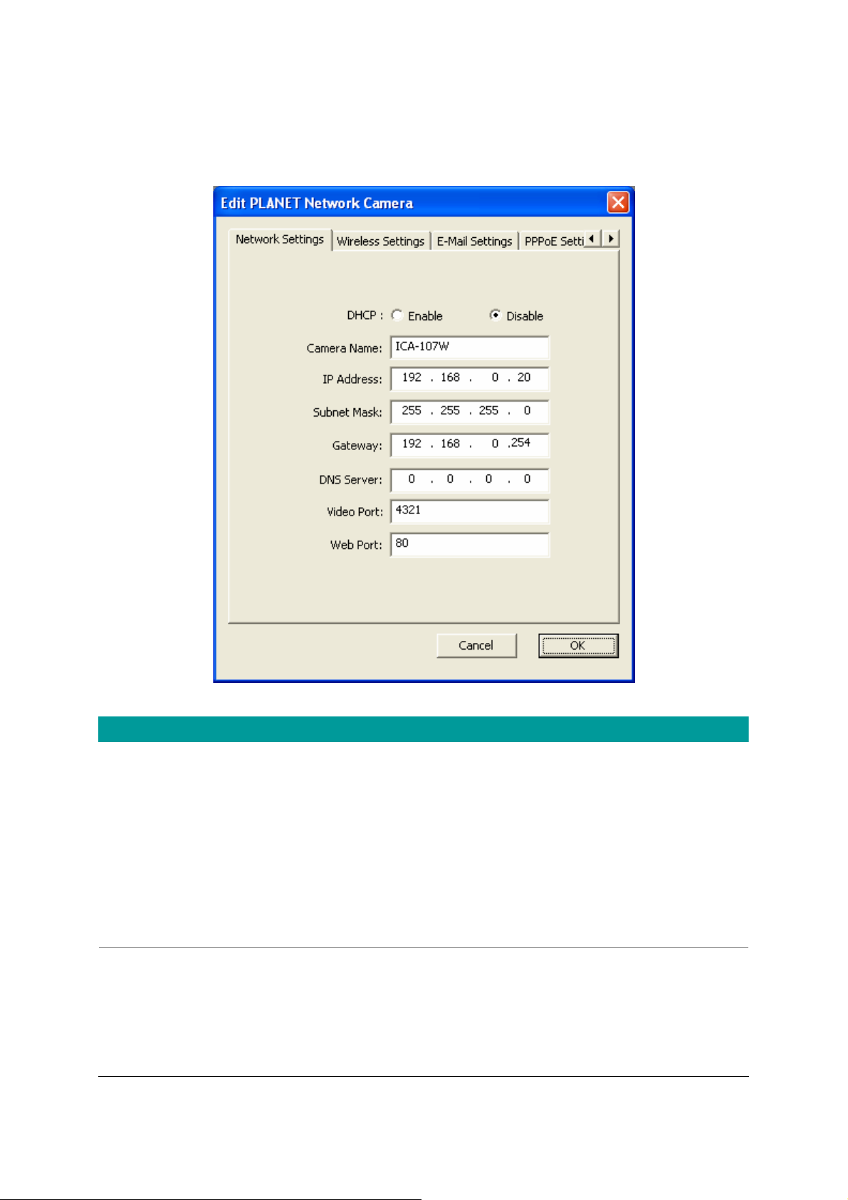
6.2.1. Network Setting
Network Setting
DHCP Enable or disable the DHCP function here.
Camera Name It is recommended to name a meaningful name for the camera.
For example, “Living Room”, “Front Door”. That will help you to
recognize the IP Camera more easily.
IP Address Please assign an available IP address to your IP Camera.
Subnet Mask Please input the subnet mask that you want to use here.
Gateway Please input the gateway that you want to use here.
DNS Server Please input the desired DNS server here.
Video Port The IP Camera uses the Video Port to transmit or receive the
video streaming. The default port is “4321”.
Web Port The default port used by the web is 80. You might use a different
port for the web of the IP Camera. If you change this to another
port number, for example, 8080, then you are required to use this
17
Page 23
10F Pl
t
dedicated port to access the web page, for example:
http://192.168.0.20:8080.
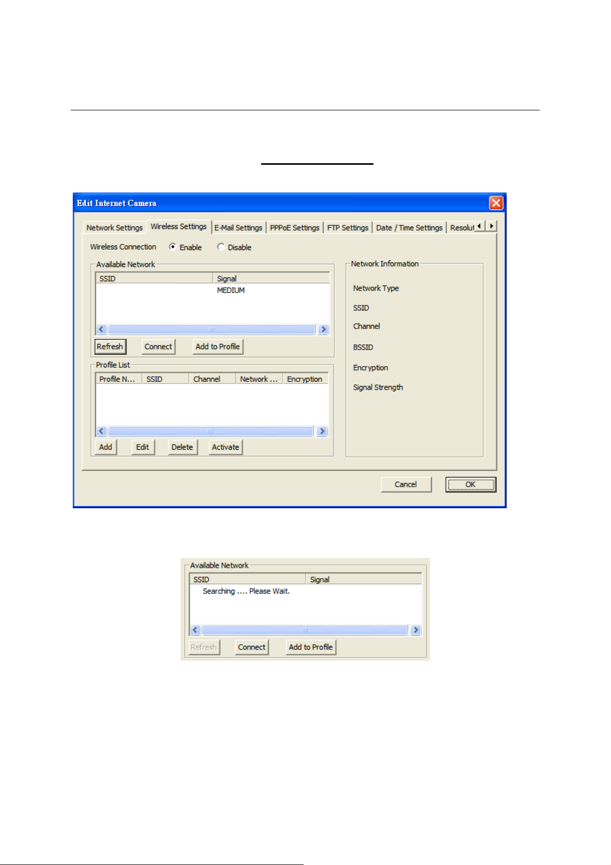
6.2.2. Wireless Settings (ICA-107W Only)
ane
The IP Camera Admin will find available wireless network automatically. You could also press
the “Refresh” button to find the available wireless network manually.
After refresh procedure, there will show the available wireless networks.
18
Page 24
10F Pl
t
10F Pl
t
ane
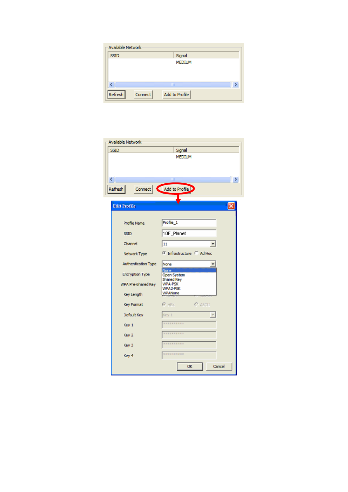
You might press “Connect” for connecting to the AP directly or “Add to Profile” to configure the
security setting of the wireless network.
ane
ICA-107W supports WEP (Open System/Shared Key), WPA-PSK, WPA2-PSK and WPANone.
Please select the responding security setting of the desired wireless network. After set the
profile, you might remove the LAN cable, and the IP Camera will connect to the AP
automatically. When the connection es ll see the w eless LED (orange color)
tablished, you wi ir
light on.
19
Page 25
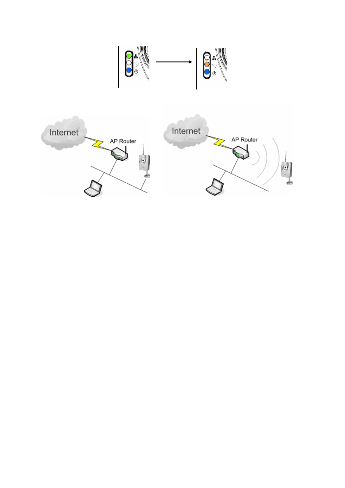
LED Status Diagram
Wired Setting Environment Wireless Setting Environment
a.) You should configure the wireless settings via the wired connection when you first
time to set the ICA-107W to wireless interface.
b.) After the configuration is done, you might remove the cable then the wireless
connection should start automatically.
20
Page 26

6.2.3. E-M
ail Setting
E-Mail Setting
Recipient E-Mail Address You can snapshot a picture and send the picture by E-Mail. Enter
the E-Mail Account for receiving the picture.
SMTP Server Enter the SMTP Server for the E-Mail sending.
Sender E-Mail Address Specified the e-mail address of sender.
Authentication Enable or Disable the SMTP Authentication function
Username When E-Mail Authentication is enabled, please input the SMTP
Username here.
Password When E-Mail Authentication is enabled, please input the
password here.
Send a Test Email Press this button to send a test e-mail to your mailbox. You can
use this function to test if your setting is correct.
21
Page 27

6.2.4. PPPoE Settings
PPPoE Settings
Enable/Disable Enable or Disable the PPPoE connection here.
Username Enter the Username of your PPPoE account.
Password Enter the Password of your PPPoE account.
MTU Maximum Transmission Unit (MTU) is the largest frame that
could be transmitted through the PPPoE connection. The MTU is
specified in octets (eight-bit bytes). If there is no other request,
please leave it as default value.
22
Page 28

6.2.5. FTP Settings
FTP Settings
FTP Server The IP Camera could upload picture to the FTP server when you
enable the motion detection function. Please enter the IP address
of the FTP server that you want to use.
FTP Port Please enter the FTP port number that your FTP server uses. In
most case, the FTP server should use TCP port 21.
User Name Specify the user account of ftp server.
Password Specify the password of your ftp account.
Remote Folder Specify the folder of the ftp site that you want to store the video.
Passive Mode If your IP Camera is under NAT, you usually need to enable this
feature.
23
Page 29

6.2.6. Date / Time Settings
Date / Time Settings
Set Date/Time manually Set the current Date and Time here.
NTP Server Enable or Disable the NTP client here.
Time Zone Select your time zone here.
NTP Server Specify the IP address of the NTP server.
24
Page 30

6.2.7. Resolution
Resolution
Resolution You might select the desired video resolution here. Available
resolutions are: 176 x 144, 320 x 240, 640 x 480.
25
Page 31

6.2.8. Advanced Setting
Advanced Setting
UPnP Enable or Disable UPnP here.
Enable/Disable DDNS Enable or disable DDNS function of the IP Camera.
Provider The IP Camera supports the service from DynDNS, for further
information, please refer to: http://www.dyndns.org
Domain Name The domain name given by DynDNS is
“registername.dyndns.com”. Please enter the domain name that
you register for the IP Camera from DynDNS web site.
Account Enter the login name for the DDNS service.
Password Enter the password for the DDNS service.
26
Page 32

6.2.9. Users
Users
Administrator Setting the password of Administrator account
Current Password Enter the current password of the IP Camera.
New Password Enter the new password you want to use for the IP Camera.
Confirm New Password Retype the new password to confirm the setting.
User You might Enable/Disable the user accounts and setting the user
name and password here. The IP Camera could support up to 4
user accounts.
27
Page 33

6.2.10. Tools
Tools
Firmware Version Display current firmware version.
Firmware Update You could upgrade IP Camera’s firmware via this function. Press
this button and select the correct firmware to upgrade.
Reset to Default If you want to reset the IP Camera to factory default, you might
click on this button. The default settings of the IP Camera are as
follows.
Camera Name: “ICA-107(W / P)”
IP Address: “192.168.0.20”
Subnet Mask: 255.255.255.0
Administrator Name: “Admin”
Password: “Admin”
Video Port: “4321”
28
Page 34

Web Port: “80”
LED Light ON/OFF You might turn all the IP Camera’s LEDs ON/OFF via this button.
It can let the people don’t know this camera is monitoring.
6.2.11. About
About
Administrator Utility
Version
Display current Administrator Utility Version.
29
Page 35

6.3. Setting Wizard
When you click the “Setting Wizard”, the IP Camera Admin will ask you to enter the
“Administrator Name” and “Password”. The default value is as follows.
Administrator Name: “Admin”
Password: “Admin"
If the name and password you entered are correct, you can start to setup the camera.
Network Setting
Camera Name It is recommended to name a meaningful name for the camera.
For example, “Living Room”, “Front Door”. That will help you to
recognize the IP Camera more easily.
IP Address Please assign an available IP address to your IP Camera.
Subnet Mask Please input the subnet mask that you want to use here.
30
Page 36

Gateway Please input the gateway that you want to use here.
DNS Server Please input the desired DNS server here.
After you finish the camera setting, the IP Camera Admin will ask if you want to start the IP
Camera Viewer. You could click on “Ok” to run the IP Camera Viewer immediately or click on
“Cancel” to run the IP Camera Viewer later.
31
Page 37

7. Using the Camera Viewer
The IP Camera Viewer allows users to view video up to four IP Cameras at the same time. It
also allows users to manual/schedule recording video and playback the video file. The status
of cameras such as frame rate, video received, and etc are also displayed on the screen at
the same time.
There are three ways to run the IP Camera Viewer:
1. Click “Start”, select “Programs”→”IP Camera”→”Camera Viewer” to run the utility.
2. Double click on the IP Camera Viewer icon (
3. Click “Setting Wizard” from IP Camera Admin and follow the instructions to launch the IP
Camera Viwer.
) to run the utility.
32
Page 38

7.1. Introduction to the Control Panel
When you start the IP Camera Viewer, you would see a Control Panel and the Viewer window.
Control Panel
Viewer Window
33
Page 39

7.2. Camera Buttons
Camera Buttons
Camera
Please click on one of these number buttons for connecting to the
selected IP Camera. If you want to remove the camera from the
IP Camera Viewer, please right click on the icon and select
“Reset Camera x”. If you want to modify the channel setting,
please right click the icon and select “Configure Camera x”.
34
Page 40

7.3. Camera Status
Above the Number button, there are status bars that will indicate the different status of the IP
Camera. Please refer to the table below to check the status of your IP Camera.
Camera Status
Yellow The channel has not been configured yet.
Blue The IP Camera is connected and playing the live video.
Pink The IP Camera is not connected now.
Red The IP Camera is recording.
7.4. Control Buttons
Control Buttons
Play
Snapshot
Stop
In Display mode, clicking on the “Play” button, the IP Camera
Viewer will connect to the disconnected IP Camera. In Playback
mode, clicking on the “Play” can play the video.
Record
Pause
Play
End the IP Camera
Viewer
Minimize the Window
Forward
Stop
Pause Clicking on the “Pause” button, the IP Camera Viewer will pause
In the Display mode, clicking on the “Stop” button, the IP Camera
Viewer will disconnect the IP Camera. In the playback mode,
clicking on the “Stop” can stop playing the video.
the current video display. You might use the “Play” button to
35
Page 41

resume the video display.
Forward
Snapshot
Record
Clicking on the “Forward” button to forward the speed when you
play the recording file.
Clicking on the “Snapshot” button will make the IP Camera
Viewer to take a snapshot of the video and save the picture as a
bitmap file in the hard disk. (You will learn how to set the directory
for storing these bitmap files at the Section 7.8.4)
By clicking “Record” button you can record video immediately.
(You will learn
section 7.8.4)
how to set the directory for storing video files at the
36
Page 42

7.5. Video Recording
The IP Camera Viewer allows you to record the video in the “.AVI” files. There are two ways of
video recording – Manual Recording and Schedule Recording.
Manual Recording
You can manually record the video stream into an assigned video file.
Click “Record”, then the IP Camera Viewer will start to record the video stream. You can
assign the path in the setting dialog.(please see section 7.8.4) Clicking “Stop” will stop
recording.
Note: Before manual recording, you have to click the camera button to select the IP Camera
that you want to record first and make sure that the IP Camera Viewer is successfully
connecting to the IP Camera.
Schedule Recording
You can assign a schedule and let the IP Camera Viewer recording the video stream
automatically. Please refer to Section 7.8 to see how to setup schedule for the recording. The
file name of the recorded video file is the start time of recording. For example, the file name
“IPCamera_2006-10-8-23-56-40.avi” means it was recorded at 2006/10/8 23:56:40.
37
Page 43

7.6. Change Resolution
The IP Camera Viewer supports two resolutions, 640x480 (VGA) and 320x240 (CIF). You can
change the resolution of each IP Camera by clicking the resolution button.
Note: Before changing the resolution of the IP Camera, you have to select the IP Camera by
clicking the camera button first. If you change the resolution of an IP Camera, other clients
who are viewing the same IP Camera will also see the video with the changed resolution.
Resolution
VGA
QVGA
Change the resolution to 640x480 (VGA).
Change the resolution to 320x240 (QVGA).
38
Page 44

7.7. View Four Cameras Simultaneously
Click the four division button can view the 4 IP Cameras simultaneously in a
four-division window.
39
Page 45

7.8. Viewer Utility Setting
Click the “Setting” button , the setting window of the IP Camera will pop up.
Note: If you want to change the settings such as IP Address, Video Port, etc. in the “Setting”
option, you must disconnect the Internet Camera first. You might disconnect the IP Camera by
clicking on the “Stop” button.
40
Page 46

7.8.1. Setting
Setting
Name
It is not required to fill the name of IP Camera for connecting. It is
for users to identify the camera.
IP Address Enter the IP address of the IP Camera you want to connect here.
Video Port
Model
Username The user name for login into the IP Camera. By default, the user
Password The password for login into the IP Camera. The default value is
Enter the port number of the video streaming used by the IP
Camera here.
Select the Model Name of the IP Camera.
name is “Admin”.
“Admin”.
Discover Clicking on the “Discover” button, the IP Camera Admin will pop
up. The window will show all the discovered cameras on LAN.
41
Page 47

7.8.2. Recording
The IP Camera Viewer support schedule recording function. The IP Camera Viewer will
record the video stream in the assigned file folder according to the schedule automatically.
The recorded video files are AVI format.
Note:
1. The IP Camera Viewer will only start to record the video stream when it is running and is
successfully connecting to the Internet camera in the beginning of the schedule.
2. The schedule setting of one-time or weekly schedule should not overlap, or the recording
will fail.
42
Page 48

One-Time Schedule
Weekly Schedule
Schedule
New
Click “New” to add a new recording schedule.
Edit Select an existing schedule in the schedule list and click “Edit” to
edit the schedule.
Delete Select an existing schedule in the schedule list and click “Delete”
to delete the schedule.
Schedule
Cycle Recording
Check this check box to enable cycle recording. When the Cycle
Recording is checked and the storage usage has already
reached the maximum reserved storage space, the IP Camera
Viewer will automatically delete the oldest recorded video file and
use the space to store the newly recorded video stream.
One-Time Schedule You can assign a period of time and the IP Camera Viewer will
43
Page 49

automatically record the video stream only during the period of
time. The default time is 2 minutes later from the current time.
Weekly Schedule You can select the days in a week and set a period of time that
you want to record the video stream.
7.8.3. Status
You can see the current status of the connection session between the IP Camera Viewer and
the IP Camera.
Status
Connected “Yes”: When the IP Camera Viewer is connecting to the IP
Camera.
“No”: When the utility is not connecting to the IP Camera.
Status
Stream Started At The starting time of the current connection between the IP
Camera Viewer and the IP Camera.
Time Elapsed The elapsed time of the current connection between the IP
44
Page 50

Camera Viewer and the IP Camera.
Video Received The total size (Unit is KByte) of video stream received from the IP
Camera.
Audio Received
(Reserved for future use.)
Frame Rate The fps (frames per second) of the current video stream.
Data Rate The data rate (KByte per second) of the current video stream.
Number of Frames The total number of video frames received during the current
connection session between the IP Camera Viewer and the IP
Camera.
Number of Users The total numbers of user that is viewing this camera.
45
Page 51

7.8.4. General
You can manage storage usage for the IP Camera here.
General
Snap Shot Directory This function lets you assign the directory where snapshot image
will be stored. The default folder is where the IP Camera Viewer
is installed, for example: “C:\Program Files\Internet Camera”.
Record Directory This function lets you assign the directory where the recorded
video files stored. The default folder is where the IP Camera
Viewer is installed, for example: “C:\Program Files\Internet
Camera”.
Free Disk Space The current free disk space of the hard drive that is assigned to
save recording files.
Max Recording Space You can reserve a disk space to store the recorded video and
snapshot files. If the space is run out, a message will pop up to
remind you.
Used Disk Space The current used disk space for saving the recording file.
Max Video File Size This function let you assign a maximum size of each video file.
The max value is 2 GB per file.
46
Page 52

7.8.5. About
About
Camera Viewer Utility
Version
Display current version of IP Camera Viewer.
47
Page 53

7.9. Playback
Click the “Open File” and the “Load File” window will be popped up. Select the file that you
want to play.
The IP Camera Viewer will start to play the selected video file.
48
Page 54

Playing Control
Play
When the video playback is in Stop state, click on the “Play”
button and the IP Camera Viewer will play the video file from the
beginning point. When the video playback is in Pause state, click
on the “Play” button and the IP Camera Viewer will play the video
file from the current pause point. When the IP Camera Viewer is
playing with fast speed, just click “Play” button to let the IP
Camera Viewer play with the normal speed.
Pause When the recorded video is playing, you can click the “Pause”
button to freeze the playback. If you want the IP Camera Viewer
49
Page 55

to continue playing from the current pause point, just click “Play”.
Stop
Playing Control
Forward
When the IP Camera Viewer is playing, you can click “Stop” to
stop the playback. If you want the IP Camera Viewer to play
again, just click “Play” and the IP Camera Viewer will play the
video file from the beginning point.
If you want the IP Camera Viewer to play the video file in a faster
speed, just click “Forward” and the IP Camera Viewer will double
the playing speed. If you want the IP Camera Viewer play with the
normal speed, just click “Play”.
50
Page 56

7.10. Rotate Video
Rotate function lets you rotate the video frame 180 of degree each time you click the “Rotate”
. With this function, you can view the live video with normal position or rotate with 180
degree.
51
Page 57

8. Web Connection and Setup
You can use the Web browser to connect the IP Camera for viewing or setting. Open the web
browser and enter the IP address of the IP Camera to establish a connection. The default IP
address of the camera is “192.168.0.20”.
When the welcome screen appears, enter the “Administrator Name” and “Password”. The
default values are:
Administrator Name: “Admin”
Password: “Admin”
When the IP Camera is connected, the browser will take you to the live video page. If you are
viewing the IP Camera at the first time, the following dialog will appear to install the ActiveX
plug in. Please check the publisher part; you should accept it, if it is published by PLANET
Technology Corp.
52
Page 58

After installed the ActiveX plug-in, the video image will be shown up in the web screen directly.
(Example on ICA-107W)
The menu options for the web control screen are as follows.
Camera – View live video and adjust the video format from the menu.
LAN – Configure the LAN port.
WLAN – Configure the WLAN port. (ICA-107W Only)
E-Mail & FTP – Setup the E-Mail client and FTP client.
53
Page 59

Motion Detection – Configure the Motion Detection here.
System – Configure the system settings here.
Status – Shows the camera information and current status in this page.
Users – The IP Camera support up to 4 user accounts. You can set those accounts here.
54
Page 60

8.1. Camera Setting
(Example on ICA-107W)
Camera Setting
Resolution Select the desired video resolution. Available resolutions are: 640
x 480, 320 x 240, and 176 x 144. The default resolution is CIF.
Image Quality Adjust the video quality here.
Max Frame Rate Set the video max frame rate. This camera can support at most
30 frames per second.
Frequency Adjust this property to fitting light frequency.
Brightness You can adjust the brightness of the video. This value can be
from 1 to 100.
Contrast You can adjust the contrast by change this value. This value can
be from 1 to 100.
Saturation You can adjust the saturation by change this value. This value
can be from 1 to 100.
Hue You can adjust the hue by change this value. This value can be
55
Page 61

from 1 to 100.
Whiteness You can adjust the white balance by change this value. This
value can be from 10 to 30.
Enable Auto Exposure You can enable Auto Exposure by check this box. IF this function
is enabled, the Brightness, Contrast, Saturation, Hue and
Whiteness adjustment would not take effect.
Apply When you finish the setting, click this button to validate the setting
values.
56
Page 62

8.2. LAN Setting
(Example on ICA-107W)
LAN
Network Type The IP Camera can obtain IP via DHCP protocol or specified a
static IP Address to it.
IP Address Enter an available IP Address within the range in your LAN.
Subnet Mask The Subnet Mask field must match the subnet setting on your
LAN. For example: 255.255.255.0.
Gateway Please enter the default gateway of your LAN here.
DNS Server Please enter your prefer DNS server here.
Video Port The Video Port is used to transmit or receive the video stream.
The default port setting is “4321”. If you want to view the video
from the camera, the port setting should be correct.
57
Page 63

Web Port The IP Camera support web connection, the default web port is
80. If you change the web port from 80 to other port, such as
8080, you must type http://192.168.0.20:8080 to connect the
camera through the web browser.
Apply When you finish the “LAN” configuration, click “Apply” to apply the
setting.
PPPoE
Enable PPPoE Enable or disable PPPoE function of the IP Camera.
User Name Enter the User Name for the PPPoE account.
Password Enter the Password for the PPPoE account.
MTU Maximum Transmission Unit (MTU) is the largest frame that
could be transmitted through the PPPoE connection. The MTU is
specified in octets (eight-bit bytes). If there is no other request,
please leave it as default value.
Apply
Dynamic DNS
Enable DDNS Enable or disable DDNS function of the camera.
Provider Several companies provide DDNS service. The IP Camera
Domain Name The domain name given by DynDNS is
User Name Enter the login name for the DDNS service.
Password Enter the password for the DDNS service.
Apply
UPnP
When you finish the “PPPoE” configuration, click “Apply” to apply
the setting.
supports the service from DynDNS company.
“registername.dyndns.com”. Enter the domain name that you
register for the camera from DynDNS web site.
When you finish the “Dynamic DNS” configuration, click “Apply” to
apply the setting.
Enable UPNP Enable or disable UPnP function of the camera.
Apply
When you finish the “UPnP” configuration, click “Apply” to apply
the setting.
58
Page 64

8.3. WLAN (ICA-107W Only)
(Example on ICA-107W)
Wireless Setting
Wireless connection Enable or disable the wireless function of the IP Camera. By
default, the function is disabled.
Network Type Infrastructure – This operation mode requires the presence of a
Wireless LAN Access Point or Router. All communication is done
via the Access Point or Router.
Ad-Hoc – Select this mode if you want to connect to another
wireless stations in the Wireless LAN network without through an
Access Point or Router.
Available Networks Select the networks listed below and click apply to connect to the
specified network.
59
Page 65

SSID The SSID (up to 32 printable ASCII characters) is the unique
name identified in a WLAN. The ID prevents the unintentional
merging of two co-located WLANs.
You may specify a SSID for the IP Camera and then only the
device with the same SSID can interconnect to the IP Camera.
Channel This setting is only available for Ad Hoc mode. Select the number
of the radio channel used for the networking.
Basic Rate The IP Camera will force to the data rate that you selected to
transmit data.
Authentication and
Encryption Type
Choose the security setting of your wireless network.
The ICA-107W supports: “None”, “Open System”, “Shared Key”
and “WPA-PSK”. When you select “WPA-PSK” authentication,
you can encryption your wireless with WPA-TKIP or WPA-AES.
WPA Pre-Shared Key The WPA-PSK key can be from 8 to 64 characters and can be
letters or numbers. This same key must be used on all of the
node in the wireless network.
WEP Key Length You may select 64-bit or 128-bit to encrypt transmitted data.
Larger key length will provide higher level of security, but the
throughput will be lower.
WEP Key Format Hexdecimal – Only “A-F“, “a-f“ and “0-9“ are allowed to be set as
WEP key.
ASCII – Numerical values, characters or signs are allowed to be
WEP key. It is more recognizable for user.
Default Key Select one of the keys (1~4) as the encryption key.
Key1 ~ Key4 Enter the WEP key you want to use here.
Apply When you finish “WLAN” configuration, click this button to apply
the setting.
60
Page 66

8.4. E-Mail and FTP
The “E-Mail & FTP” lets you setup E-Mail client and FTP client that camera can sent image to
your e-mail account or FTP server when Motion has been detected.
(Example on ICA-107W)
Email & FTP
Recipient E-Mail Address The IP Camera supports “Motion Detection” function. Enter the
E-Mail Account for receiving the alert mail.
SMTP Server Enter the SMTP Server for sending the E-Mail.
Sender E-Mail Address Specified the e-mail address of the e-mail sender.
SMTP Authentication Enable or Disable the SMTP Authentication function
Username When Authentication is enabled, please input the SMTP
Username here.
Password When Authentication is enabled, please input the account
password here.
Send a Test Email Press this button to send a test e-mail. You can use this function
61
Page 67

to test if your setting is correct.
FTP Server The IP Camera supports “Motion Detection” function. When
Motion Detection event occurred, you can record the pictures to
FTP server. Enter the FTP address for uploading the pictures.
FTP Port Enter the FTP port that the FTP server uses.
User Name Specify the user account of ftp server.
Password Specify the password of your ftp account.
Remote Folder Specify the folder of the ftp site that you want to store the image.
Password When Authentication is enabled, input the account password.
Passive Mode If your IP Camera is behind the NAT, you usually need to enable
this feature.
62
Page 68

8.5. Motion Detection
The “Motion Detection” allows users to setup the behavior of motion detection feature.
(Example on ICA-107W)
Motion Detection
Motion Detection Enable Enable or Disable the Motion Detection Function.
Next Event Detected
Interval
Threshold Setup the sensitivity of motion detection.
Send Recording File to
E-Mail
E-Mail Subject Specify the subject of motion detection alert e-mail.
Send snapshot file to FTP Select “Yes” to send the recorded video file to your FTP server
Setup the interval between two events. For example, if you setup
the interval to 5 seconds, the next event will start after this event
finished + 5 seconds.
Select “Yes” to send the alert email with the recorded image to
the e-mail account that you had specified in the “E-Mail & FTP”
page.
that you had specified in the “E-Mail & FTP” page.
63
Page 69

8.6. System
The “System” allows users to setup the IP Camera’s parameters, like camera name, data/time
setting. And also provide firmware upgrade and reset tools at this page.
(Example on ICA-107W)
System
Camera Name The default camera name is “ICA-107(W / P)”. It is recommended
to name a meaningful name for the IP Camera.
Password
Confirm Password
Set Date/Time manually
and Synchronize to PC
time
NTP Server (Radio Box) To enable the NTP function.
Time Zone Select the time zone where your camera is located.
NTP Server Specify the IP Address of the NTP Server here.
Enter the password for the default account. The password should
be 4 digits.
Enter the password again to confirm the setting.
You can set the IP Camera’s Date/Time manually. Or you can
just click on the Synchronize to PC time to let the IP Camera
synchronize its time to your PC automatically.
64
Page 70

Upgrade Firmware You can upgrade the IP Camera’s firmware via this function.
Press the browse button, find the correct firmware and press
upgrade.
Reset to Factory Defaults If you want to reset all the settings to factory default, please use
this function to fulfill your task.
Reboot Device To reboot the IP Camera, click “Reboot”.
LED Setting If you wan to secure the IP Camera from noticing, you can turn off
the LED light by clicking “LED Light OFF”. To turn on the LED
light, just click “LED Light ON”.
65
Page 71

8.7. Status
The “Status” shows the current firmware version, uptime, system time and IP information of
this camera.
(Example on ICA-107W)
66
Page 72

8.8. Users
The “Users” allows you to add four user accounts which are able to view video from the IP
Camera Viewer and Web Management. These users, unlike Administrator, are not allowed to
configure the IP Camera.
User 1 / 2 / 3 / 4
User #
Login
Password
Confirm Password
Apply
(Example on ICA-107W)
Enable or Disable the user number #.
Enter the login name of the user account.
Enter up to 4 digits password for the new user account.
Enter the password again to confirm the setting.
Click “Apply” to save the user account setting.
67
Page 73

8.9. Log
The “Log” allows users to monitor the device event and time. If you have trouble to use this
device, the log file will help administrator to know the status of device.
Log
Log screen
Refresh
(Example on ICA-107W)
The screen will show event and event time of device.
You can press “Refresh” button to refresh the log screen.
68
Page 74

9. Technical Specifications
Video specification
Max Resolution: 640 x 480 pixels
Sensor: 300K pixels 1/4" color CMOS sensor
Gain control: Automatic
Exposure: Automatic
White Balance: Automatic
Lens: Manual Focus, F=1.8
Image (Video Setting)
Image compression: MJPEG Image Video
Digital 24-bit Color
Frame rate: Up to 30fps
Video resolution: 176 x 144, 320x240, 640x480
System Hardware
LAN Connector: One RJ-45 port to connect to 10/100Mbps Ethernet
Wireless: IEEE 802.11b/g(ICA-107W Only)
PoE: 802.3af(ICA-107P Only)
LED Indicator: LAN LED, WLAN LED (ICA-107W Only), Power LED
Power Supply: 12V / 1A (ICA-107W)
Power Supply: 12V / 0.4A (ICA-107 / ICA-107P)
EMI & Safety
FCC, CE!
69
Page 75

10. Appendix A Router/Gateway Setup for Internet
Viewing
To view IP Camera across the Internet, you have to make sure Router/Gateway has
configured to pass incoming TCP/UDP connections from remote PC to the IP Camera. The
Router/Gateway should set port forwarding or virtual server for the connections. Please see
the
illustration as below.
Router/Gateway Port Forwarding/Virtual Server Setup
Name Protocol Port LAN IP
Setup 1 TCP 80 192.168.0.20
Setup 2 TCP 4321 192.168.0.20
Port Definition
Setup 1 It is the port of Web port. You have to configure the protocol to
“TCP”.
Setup 2 It is the port of Video port. You have to configure the protocol to
“TCP”.
Viewing Internet Camera via Web Browser
Setup 1/Setup 2 If you want to view the video via Web Browser from Internet, you
have to ensure the Router/Gateway has configured both setup1
and setup 2. If the web port is not default port “80”, but changed
to 8080. The remote user has to enter http://210.66.155.85:8080.
Without Setup 2, you will not see the video streaming in this PC.
Viewing Internet Camera via Camera Viewer Utility
Setup 2
If you want to use IP Camera Viewer Utility to view the camera
from Internet, please make sure the Router/Gateway has
70
Page 76

configured Setup2.
71
Page 77

11. Appendix B Viewing via UPnP in Windows XP
When the UPnP function is enabled, the camera can be detected by UPnP compliant system
such as Windows XP. The camera will be displayed in My Network Place, so you can double
click the camera or right click the camera and select “Invoke” to view the video through web
browser.
72
Page 78

Enable UPnP in Windows XP SP2
If you can’t find the IP Camera in the My Network Place or you have seen the following
message when you double click the IP Camera. You have to check if UPnP function is
blocked by the firewall. Please follow the steps below to enable it.
1. Go to “Start\Settings\Network Connections”.
2. Right click the “Local Area Connection” and select “Properties”.
3.
In the “Local Area Connection Properties”, select “Advanced” option menu and click
“Settings”.
73
Page 79

4. The “Windows Firewall” screen will be popped up, select “Exceptions” option menu.
74
Page 80

5. Enable “UPnP Framework” from the “Programs and Services list” and click “Ok”.
75
Page 81

76
Page 82

12. Appendix D Configure Windows 2003 Server
Graphics Hardware Acceleration and DirectX are disabled by default on a Server
configuration to ensure maximum stability and uptime. But for any reason you need to enable
them to use DirectX enabled applications this section will guide you through on how you can
do it.
Enabling Graphics Hardware Acceleration
1. Simply right click anywhere on your desktop and select Properties -> Settings tab ->
Advanced -> and finally, the Troubleshoot tab.
2. Now move the Hardware acceleration slider across to Full
3. Click OK
4. You may experience a monitor black out for a few seconds, this is normal.
77
Page 83

Enabling DirectX
5. x
Click on Start -> Run -> and type dxdiag followed by enter. You will get a dialog bo
asking if you want to allow d
xdiag to access the internet to check for valid WHQL
certificates - click on Yes.
6. click on all three boxes to enable DirectDraw, Direct3D
Let's click on the Display tab, now
and AGP Texture Acceleration.
78
 Loading...