

Page 1

IR IP Camera
ICA-106
User’s Manual
Version: 1.0
(May, 2006)
1/60
Page 2

Copyright
Copyright© 2006 by PLANET Technology Corp. All rights reserved. No part of this publication
may be reproduced, transmitted, transcribed, stored in a retrieval system, or translated into any language
or computer language, in any form or by any means, electronic, mechanical, magnetic, optical, chemical,
manual or otherwise, without the prior written permission of PLANET.
PLANET makes no representations or warranties, either expressed or implied, with respect to the
contents hereof and specifically disclaims any warranties, merchantability or fitness for any particular
purpose. Any software described in this manual is sold or licensed "as is". Should the programs
prove defective following their purchase, the buyer (and not this company, its distributor, or its dealer)
assumes the entire cost of all necessary servicing, repair, and any incidental or consequential damages
resulting from any defect in the software. Further, this company reserves the right to revise this
publication and to make changes from time to time in the contents hereof without obligation to notify
any person of such revision or changes.
All brand and product names mentioned in this manual are trademarks and/or registered trademarks of
their respective holders.
Federal Communication Commission Interference Statement
This equipment has been tested and found to comply with the limits for a Class B digital device,
pursuant to Part 15 of FCC Rules. These limits are designed to provide reasonable protection against
harmful interference in a residential installation. This equipment generates, uses, and can radiate radio
frequency energy and, if not installed and used in accordance with the instructions, may cause harmful
interference to radio communications. However, there is no guarantee that interference will not occur in
a particular installation. If this equipment does cause harmful interference to radio or television
reception, which can be determined by turning the equipment off and on, the user is encouraged to try to
correct the interference by one or more of the following measures:
1. Reorient or relocate the receiving antenna.
2. Increase the separation between the equipment and receiver.
3. Connect the equipment into an outlet on a circuit different from that to which the receiver is
connected.
4. Consult the dealer or an experienced radio technician for help.
FCC Caution:
To assure continued compliance.(example-use only shielded interface cables when connecting to
computer or peripheral devices). Any changes or modifications not expressly approved by the party
responsible for compliance could void the user’s authority to operate the equipment.
This device complies with Part 15 of the FCC Rules. Operation is subject to the Following two
conditions: (1) This device may not cause harmful interference, and (2) this Device must accept any
interference received, including interference that may cause undesired operation.
Federal Communication Commission (FCC) Radiation Exposure Statement
This equipment complies with FCC radiation exposure set forth for an uncontrolled environment. In
order to avoid the possibility of exceeding the FCC radio frequency exposure limits, human proximity
to the antenna shall not be less than 20 cm(8 inches) during normal operation.
R&TTE Compliance Statement
This equipment complies with all the requirements of DIRECTIVE 1999/5/CE OF THE EUROPEAN
PARLIAMENT AND THE COUNCIL OF 9 March 1999 on radio equipment and telecommunication
terminal Equipment and the mutual recognition of their conformity (R&TTE)
The R&TTE Directive repeals and replaces in the directive 98/13/EEC (Telecomm unications Term inal
Equipment and Satellite Earth Station Equipment) As of April 8,2000.
2/60
Page 3

Safety
This equipment is designed with the utmost care for the safety of those who install and use it. However,
special attention must be paid to the dangers of electric shock and static electricity when working with
electrical equipment. All guidelines of this and of the computer manufacture must therefore be allowed
at all times to ensure the safe use of the equipment.
WEEE regulation
To avoid the potential effects on the environment and human health as a result of the presence
of hazardous substances in electrical and electronic equipment, end users of electrical and
electronic equipment should understand the meaning of the crossed-out wheeled bin symbol.
Do not dispose of WEEE as unsorted municipal waste and have to collect such WEEE
separately.
Revision
User’s Manual for PLANET IR IP Camera
Model: ICA-106
Rev: 1.0 (May, 2006)
Part No. EM-ICA106
3/60
Page 4

Table of Contents
Chapter 1 Overview........................................................................................................ 5
1.1 Introduction ................................................................................................... 5
1.2 Features:......................................................................................................... 5
1.3 Application:................................................................................................... 6
1.4 System Requirement...................................................................................... 6
1.5 Package Contents........................................................................................... 6
Chapter2 Hardware Connections.................................................................................. 7
2.1 Hardware Installation .................................................................................... 9
Chapter3 Login to Homepage ..................................................................................... 11
3.1 Before Operation ......................................................................................... 11
3.2 Enabling UPnP for Windows® XP™........................................................... 12
3.3 Install the Camera with a Router................................................................. 17
3.4 Before connected via web browser.............................................................. 19
3.5 The first time access via web browser......................................................... 19
3.6 Logging in as a User.................................................................................... 20
3.7 Logging in as an Administrator ...................................................................21
Chapter 4 Operating the Network Camera .................................................................. 22
4.1 Control Panel............................................................................................... 23
4.2 Advanced Function Area............................................................................. 25
4.2.1 Home .................................................................................................... 25
4.2.2 Setting................................................................................................... 26
4.2.2.1 System.................................................................................... 27
4.2.2.2 Network.................................................................................. 29
4.2.2.3 Video/Audio ........................................................................... 32
4.2.2.4 User ........................................................................................ 35
4.2.2.5 Motion Detection.................................................................... 36
4.2.2.6 Status ...................................................................................... 38
4.2.2.7 Factory Default....................................................................... 39
4.2.2.8 Restart..................................................................................... 39
4.2.1.9 Upgrade:................................................................................. 40
4.3 Capture ................................................................................................. 43
4.4 Recording ............................................................................................. 44
Appendix A: Restore Factory Default Settings .................................................................45
Appendix B: Troubleshooting & Frequently Asked Questions.......................................... 46
Appendix C: PING IP Address.......................................................................................... 50
Appendix D: Bandwidth Estimation.................................................................................. 51
Appendix E: Specifications............................................................................................... 52
Appendix F: Time Zone Table........................................................................................... 54
Appendix G: DDNS Application....................................................................................... 56
4/60
Page 5

Chapter 1 Overview
This user’s guide explains how to operate the Network Camera from a computer. This
user’s guide is written to be read on the computer display. However, users might
consider printing it out to access easily and read it before you operate the Network
Camera.
1.1 Introduction
This Network Camera is an inexpensive and fully scalable surveillance technology.
Because the Network Cameras can be plugged in to your existing computer network
infrastructure, you will potentially save thousands of dollars on unnecessary cabling.
The Network Camera is accessible via the LAN / WLAN or Internet connection. Connect
your Network Camera directly to a computer network or DSL modem, and with a
standard Web browser you get instant, on demand video streams. Within minutes you
can set up the Network Camera to capture a video sequence to a PC. Live video image
can be uploaded to a website for the world to see or made available only to select users
on the network.
1.2 Features:
z MPEG4 / JPEG dual video compression
z 6 high-light IR LEDs for 0 Lux operation
z High quality 1/4” CMOS image sensor
z Pre recording for motion triggered up to 15 seconds
z Wired and Wireless LAN interface
z Up to 400% digital zoom
z Built-in internal microphone
z Remote-Control via Internet Explorer
z Support statistic and dynamic IP address
z DDNS and UPnP
z Multi-channel control software for surveillance application
z On-line firmware upgrade
5/60
Page 6

1.3 Application:
z Remote monitoring
z Surveillance
1.4 System Requirement
z Microsoft Internet Explorer 5.5 or later
z VGA Monitor resolution 1024 x 768
z Pentium4 1.3GHz or above
z Memory Size: 256MB or above
z Windows ME, 2000, XP, or 2003
1.5 Package Contents
User can find the following items in the package:
1. IR IP Camera x 1
2. Camera Stand x 1
3. Power Adapter x 1
4. User’s Manual CD x 1
5. Quick Installation Guide x 1
If any of the above items are missing, please contact your dealer immediately.
Note: Using a power supply with a different voltage than the one included with the
Network Camera will cause damage and void the warranty for this product.
6/60
Page 7
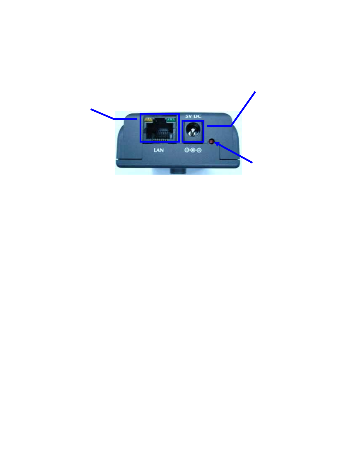
Chapter2 Hardware Connections
DC Power
LAN Socket
and LEDs
DC Power Jack
The DC power input jack is located on the Network Camera’s bottom. The input power is
5VDC. Note that supply the power to the Network Camera with standard power adapter
included in package. Otherwise, the improper power adapter may damage the unit and
result in danger.
LAN Socket
Beside the DC power Jack, the LAN socket is an RJ-45 connector for connections to
10Base-T or 100Base-TX Fast Ethernet cabling. Please use Category 5 “straight
through” cable to connect the Network Camera to an Ethernet network switch or hub.
10/100M Ethernet LEDs
LED stands for Light-Emitting Diode. The Ethernet LEDs are located on the RJ-45
connector. These LEDs are used to indicate the status of Network connection.
Factory Default Reset
This button is hidden in the pinhole under then Network Camera’s bottom. Please refer
to the Appendix A in this manual for more information.
Jack
Factory
Default Reset
7/60
Page 8
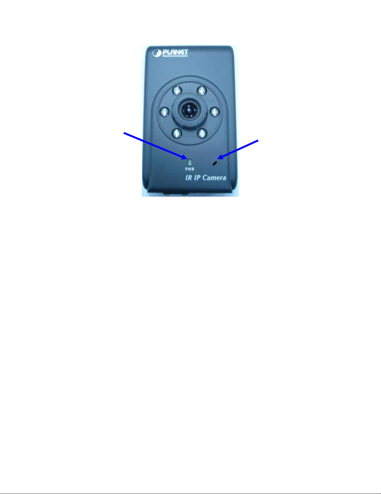
Status
Microphone
Microphone
The Network Camera’s has built-in an internal microphone. This microphone is also
hidden in the pinhole located on the front panel.
Status LEDs
This LED is used to indicate the status of Network Camera.
8/60
Page 9
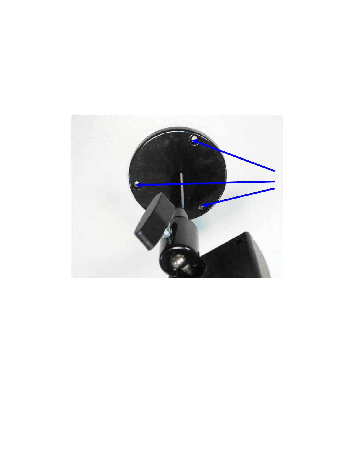
2.1 Hardware Installation
1. Attach the Network Camera with the included stand
2. Place the Camera on the table or fix it onto ceiling or wall
Use screws to fix the Network Camera onto the ceiling or wall. You could also put
the Network Camera on the table directly.
Fixed it by
3. Plug an Ethernet cable into the Network Camera
Connect an Ethernet cable to the LAN socket located on the Network Camera’s bottom
and attach it to the network.
9/60
Page 10
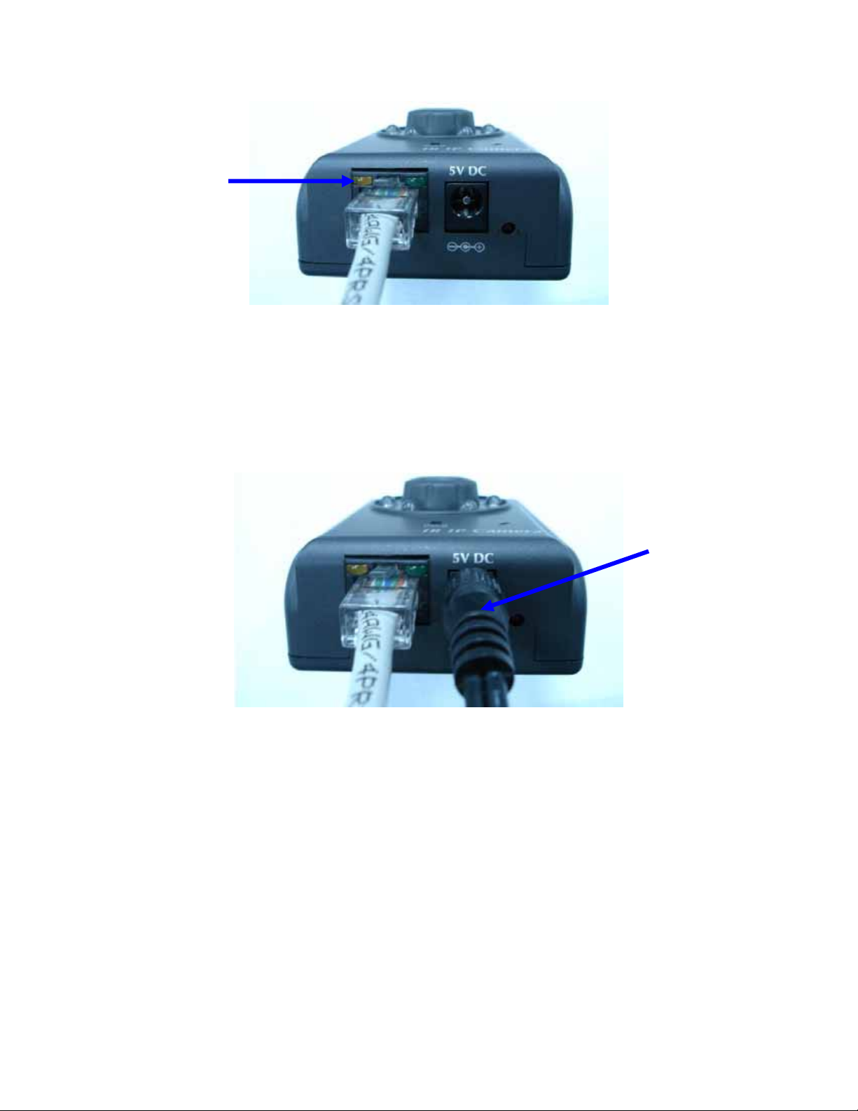
Ethernet
4. Connect the external power supply to Network Camera
Connect the external power supply to the DC power jack of the Network Camera. Note:
Use the power adapter, 5VDC, included in the package and connect it to wall outlet for
AC power.
Power
Once you have installed the Network Camera well and powered on, the status LED will
turn green first and then orange. It means the system is booting up successfully.
Furthermore, if you have a proper network connection, and access to the Network
Camera, the 10/100M LAN LED will flash green
10/60
Page 11
Chapter3 Login to Homepage
3.1 Before Operation
Install the IP Address of Network Camera
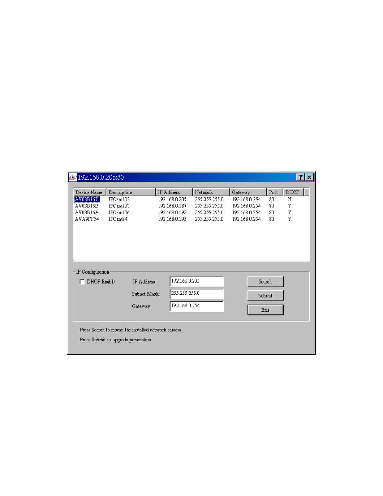
When you installed your Network camera on your LAN environment, you may execute
“MP4 IP Finder.exe” to discover Network camera’s IP address.
“MP4 IP Finder.exe” is used to scan the Installed Network Camera on a LAN, setting the
Network Camera Name, IP address settings and so on.
Using your mouse to select any one of the Network Cameras within your LAN
environment, you can search out its IP address and other IP parameters as follows:
1. Edit the IP address of this Network Camera.
2. Edit the Gateway Address if necessary.
3. Edit the Network Mask if necessary.
4. ‘Submit’ it.
11/60
Page 12
5. The Network Camera will restart the system to validate the new setting
after seconds.
Alternatively, user can use another approach to search out the Network Camera on the
LAN by UPnP as bellow:
3.2 Enabling UPnP for Windows® XP™
UPnP™ is short for Universal Plug and Play, which is a networking architecture that
provides compatibility among networking equipment, software, and peripherals. This
device is an UPnP enabled Network Camera. If the operating system, Windows XP, of
your PC is UPnP enabled, the device will be very easy to configure. Use the following
steps to enable UPnP settings only if your operating system of PC is running Windows
XP. Note that Windows 2000 does not support UPnP feature.
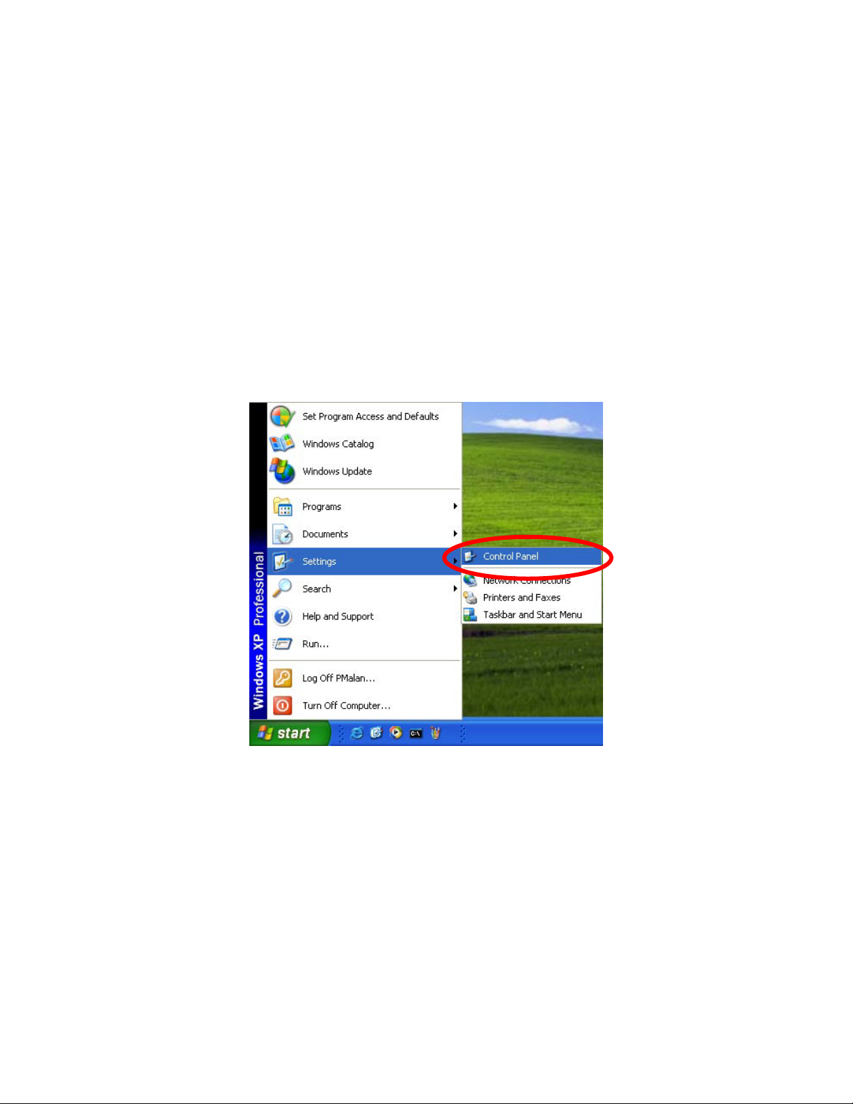
Go to Start > Settings.
Click Control Panel
12/60
Page 13
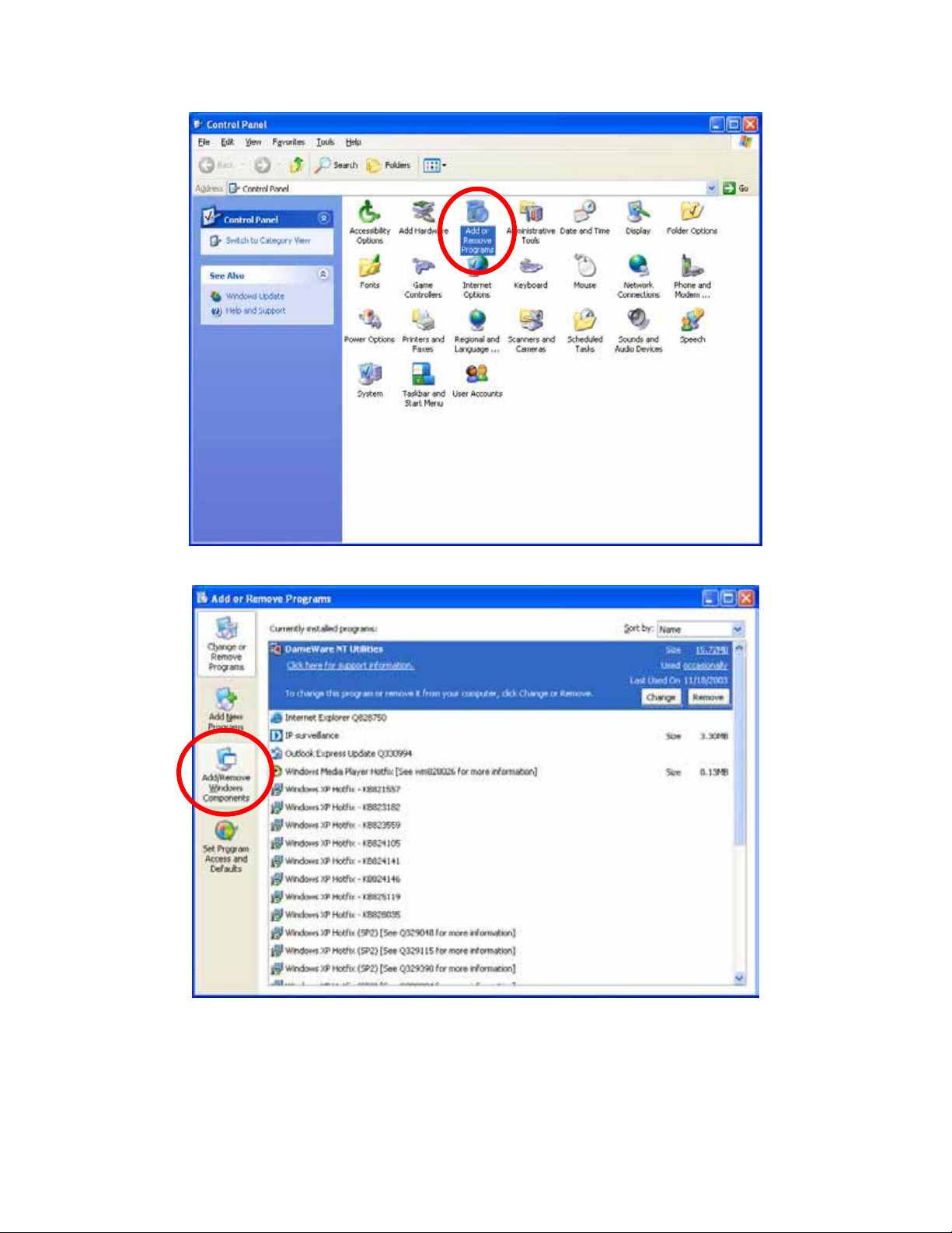
Click Add or Remove Programs
Click Add/Remove Windows Components
The following screen will appear:
13/60
Page 14
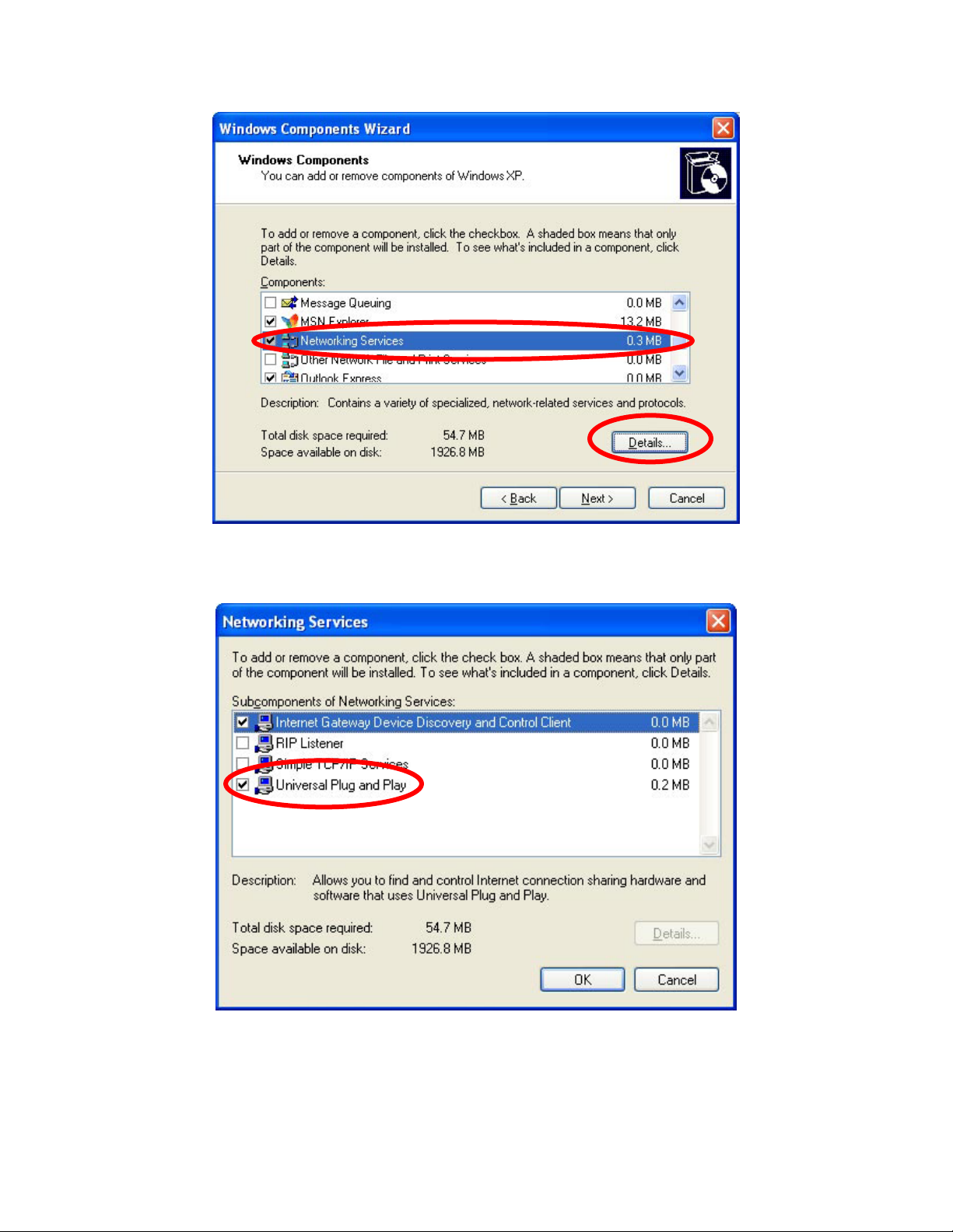
Select Networking Services
Click Details
Select Universal Plug and Play
Click Ok
14/60
Page 15
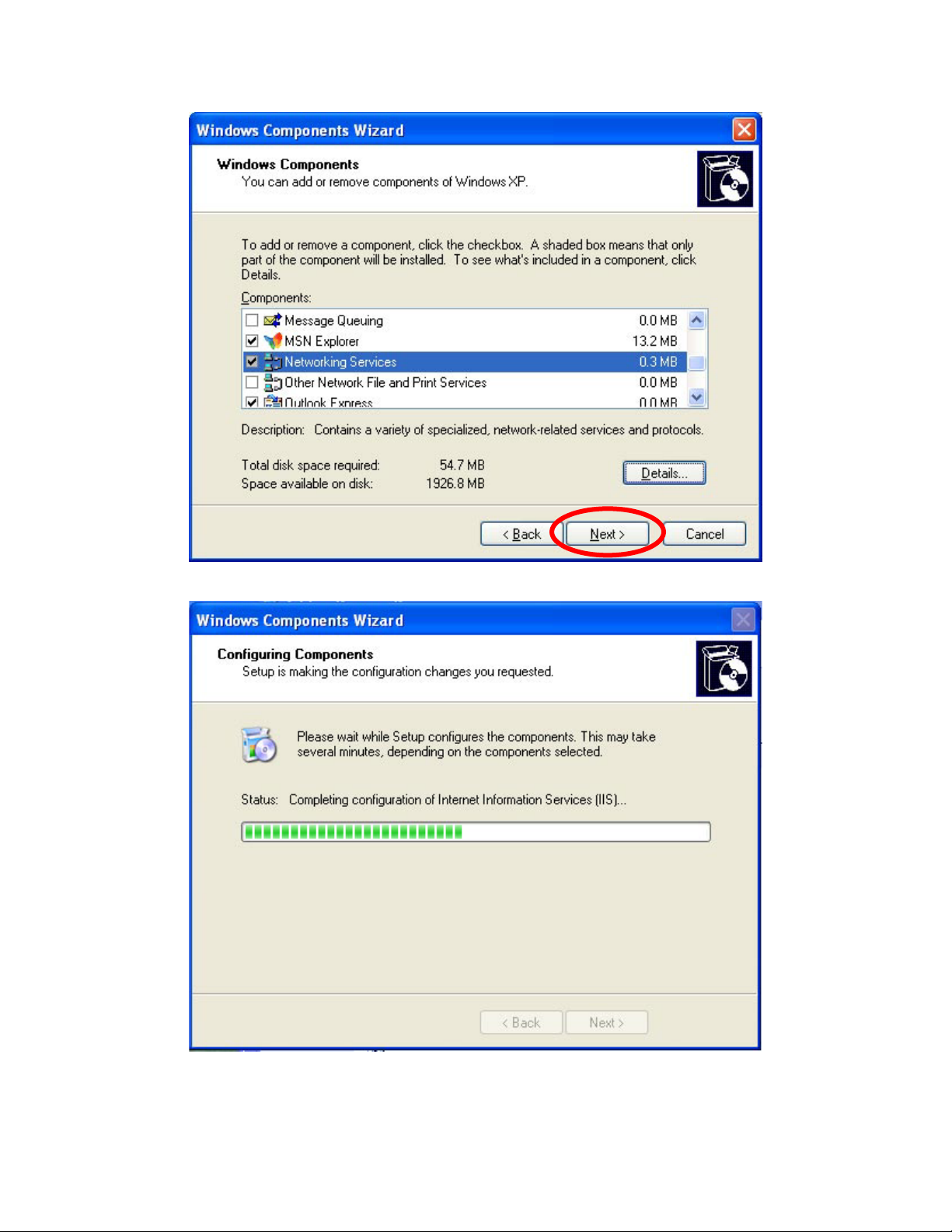
Click Next
Please wait while Setup configures the components.
15/60
Page 16
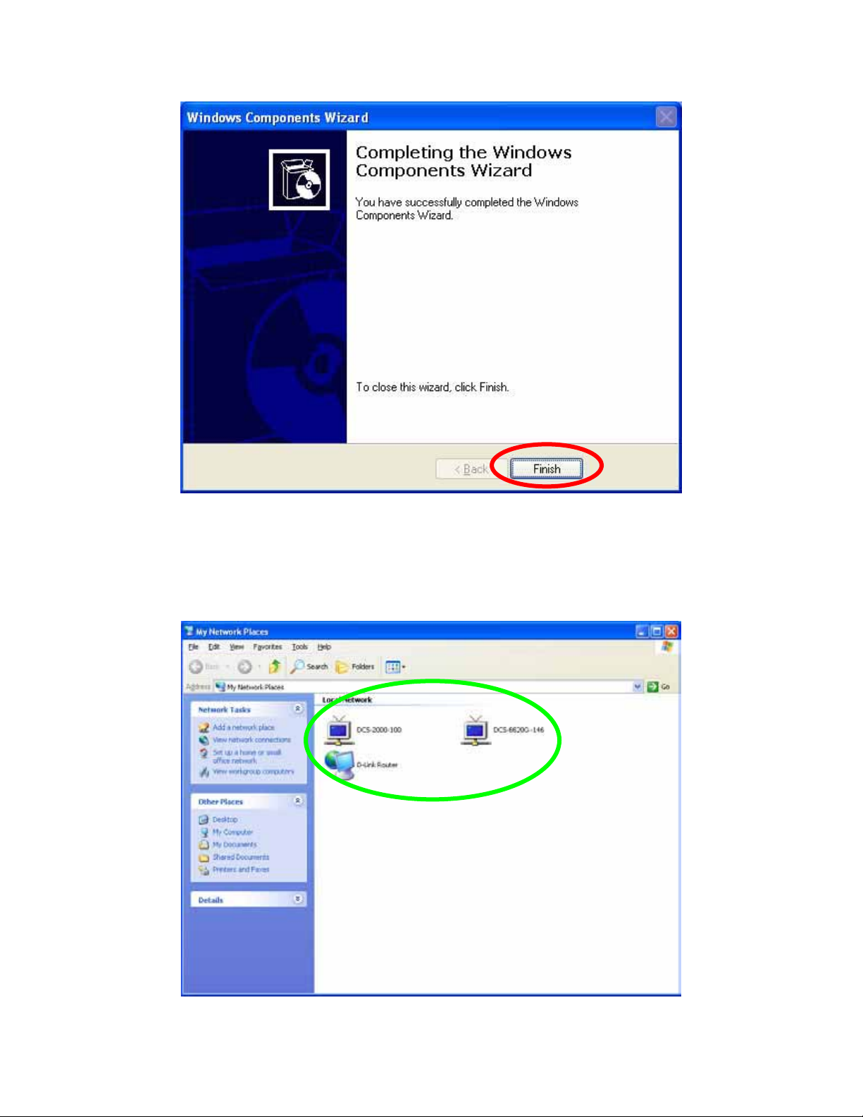
Click Finish
To view your Network Camera in an Internet browser, go to your Desktop and click My
Network Places.
Click My Network Places
Click the targeted Network Camera
16/60
Page 17

The last three digits (146), represent the fourth octet of your Network Camera’s IP
address (in this example, 198.168.0.146).
3.3 Install the Camera with a Router
The Network Camera can be used with a router. This section explains how to view the
camera from either the Internet or from inside your LAN.
installed on the LAN with a router, then it can get a dynamic IP address from the DHCP
server. However, if the Network Camera wants to be accessed from the WAN, its IP
address needs to be setup as fixed IP, also the Virtual Server function of router needs to
be setup.
Installing a Network Camera with a router on your network is an easy 3–step procedure:
(1) Assign a local IP Address to your Network Camera
(2) Access the Router with Your Web browser
(3 ) Open Virtual Server Ports for Your Router (Enable Remote Viewing)
(1) Assign a local fixed IP address to your Network Camera
Follow the steps in the Quick Installation Guide to configure the Network Camera. The
camera will be assigned a local fixed IP Address that allows it to be recognized by the
router. Manually setup the Network Camera as fixed IP, for example, such as
192.168.0.120.
(2) Access the Router with Your Web browser
If you have cable or DSL service, you will most likely have a dynamically assigned WAN
IP Address. ‘Dynamic’ means that your router’s WAN IP address can change from time
to time depending on your ISP. A dynamic WAN IP Address identifies your router on the
public network and allows it to access the Internet. To find out what your router’s WAN
IP Address is, go to the Status screen on your router and locate the WAN information
for your router.
Note: Because a dynamic WAN IP can change from time to time depending on your
ISP, you may want to obtain a Static IP address from your ISP. A Static IP address is a
fixed IP address that will not change over time and will be more convenient for you to
use to access your camera from a remote location. If you could not get a Static IP
address from your ISP, the DDNS is a solution alternatively. Please refer to Appendix G
for more information.
If the Network Camera was
17/60
Page 18

(3) Open Virtual Server Ports to enable remote image viewing
The firewall security features built into the most routers prevent users from accessing the
video from the Network Camera over the Internet. The router connects to the Internet
over a series of numbered ports. The ports normally used by the Network Camera are
blocked from access over the Internet. Therefore, these ports need to be made
accessible over the Internet. This is accomplished using the Virtual Server function on
the router. The Virtual Server ports used by the camera must be opened through the
router for remote access to your camera.
Due to each router have different settings. You may refer to the below steps to configure
your router’s Virtual Server settings
• Enabled Virtual Server function.
• Enter a unique name for each entry.
• Select Both under Protocol Type (TCP and UDP).
• Enter your camera’s local IP Address (e.g., 192.168.0.120, for example) in the
Private IP field.
• If you are using the default camera port settings, enter 80 into the Public and
Private Port section.
• If there has Scheduling option, it should be set to Always so that the camera
images can be accessed at any time.
Important: Some ISPs block access to port 80. Be sure to check with your ISP so that
you can open the appropriate ports accordingly. Some ISPs block traffic on commonly
used ports to conserve bandwidth. If your ISP does not pass traffic on port 80, you will
need to change the port the camera uses from 80 to something else, such as 8080. Not
all routers are the same, so refer to your user manual for specific instructions on how to
open ports.
Enter valid ports in the Virtual Server section of your router
Please make sure to check the box on this line to enable settings
Then the Network Camera can be access from WAN by the router’s WAN IP Address.
18/60
Page 19

3.4 Before connected via web browser
The Network Camera web page communicates with the Network Camera using an
ActiveX control. The ActiveX control component must be installed on your PC in advance.
To download ActiveX control component, user must install the Liveplayer application
program. Please refer to Liveplayer manual for detail.
By now, you have finished your entire PC configuration for Network Camera.
3.5 The first time access via web browser
1. Start the web browser on the computer and type the IP address of the Network
Camera you want to monitor as below:
The Login Window of the Network Camera is displayed:
19/60
Page 20

2. Type in your login name and password under “USERNAME” and “PASSWORD”
textbox.
For the first time use (default value), input the
User Name: admin
Password: admin
That’s, type in “admin” on the “User Name” as a default name and “admin” on
“Password”. Click “OK” button to start the main menu.
Now, you login to the Network Camera as a full-authorized administrator. You can
enter “Setting” to change the password and setup “Administrator” or “User” authority.
Please refer to “Setting” Î “User”
3. Display the image. The video will be displayed.
3.6 Logging in as a User
There are two levels of privilege, “view” and “config”, if you log in the Network Camera
as a user.
The first one is a user with “view” privilege. The “view” user can only view the video and
or audio streaming. Can not do anything else.
20/60
Page 21

The second one is a user with “config” privilege. The “config” user can view the video
and or audio streaming. Also user can change the settings in the “Home” and “Setting”
pages except “user” and “Factory Default” options. Furthermore, “Capture” and
“Recording” will be not available.
3.7 Logging in as an Administrator
If you log in the Network Camera as the Administrator, you can perform all the settings
provided within the software. The Administrator may be logged in at any time, regardless
of the number of the users being accessed.
21/60
Page 22

Chapter 4 Operating the Network Camera
Start-up screen will be as follow no matter an ordinary users or an administrator.
Control Panel
Advanced Function
Viewing Area
Viewing Area: Images from the Network Camera
Scale UP: Click this button to scale up the image on the screen
Scale Down: Click this button to scale down the image on the screen
Snap / Record to: Enter the path to save the image or files.
22/60
Page 23

4.1 Control Panel
Control Panel Area: Network Camera Manipulation and picture quality control
Item Button Meaning
1 Quality Adjust video quality.
High: Video is better but frame rate may be slower
Low: Video is poor but frame rate may be higher
Normal: System default value
2 Max Frame
Rate
3 Exposure Choose auto or fixed exposure of camera
4 Brightness Adjust picture brightness of camera
5 White
Balance
Adjust the frame rate of video stream
Choose auto or fixed white balance of camera
23/60
Page 24

6 Contrast Adjust picture contrast of camera
7 Camera
position
- Desktop
- Ceiling
- Mirror
8 Zoom Adjust ratio of digital zoom in
9 IR Turn on or off the built-in IR LEDS. Or you can set a schedule to
let the IR on/off.
Note: Select “OK” to save and enable the setting.
24/60
Page 25

4.2 Advanced Function Area
Advanced function area: only available for administrator. It has contained four
categories.
Home The home page of the Network Camera. Setting System Configuration Capture Capture current screen and save to HDD or other media Recording Record current video stream and save to HDD or other media
Setting menu consists of some sub-menu. Click on each menu to display its setting
page.
4
4.2.1 Home
When the “Home” button pressed, you will back to the main screen.
25/60
Page 26

4.2.2 Setting
Setting
Symbol Item Action
System Define camera name. Set time and date of the Network
Camera. Enable/disable NTP function. System power on
Network Configure Network setting such as DHCP On/Off, DDNS and
Video/Audio Adjust camera parameters and video / audio settings.
User Setup user name, password and login privilege
Motion
Detection
Status System information, status, and log.
notification.
UPnP.
Setup motion detection and trigged SMTP and/or FTP
accounts.
Factory
Default
Restart Reboot this device
Upgrade Firmware upgrade
Recall the Network Camera to factory default setting
26/60
Page 27

4.2.2.1 System:
Define system parameters, NTP, and notification
System Settings:
- Device Name:
It’s a unique number for each Network Camera for identification.
- Description:
You can enter the name of this unit here. It’s very useful to identify the specific
device from multiple units. Note that use “_” or “-“ to replace “space” character
to separate the name string. For example, “IP_CAM” or “IP-CAM” will be ok but
“PT IP” will not work here.
You can setup the Network Camera time manually or make it synchronized with remote
server. Also, you may select your time zone in order to synchronize time locally.
27/60
Page 28

- Time:
Change the time according to the “hh:mm” and by 12 hours format.
- Date:
Change the date according to the “mm/dd/yyyy” format
- Time zone:
Select the time zone setting accordingly.
NTP:
- Time Server:
Choose “enable” will get the time for NTP server periodically.
- Server Address:
Key in the IP address of NTP server.
- Update Schedule:
Choose the update schedule with NTP server by daily, weekly, or monthly.
IP Address Notification:
- Notify by E-Mail:
If enable this option, then when Network Camera connected to Internet, a mail
that contains related information will be mailed to preset e-Mail address.
- E-Mail To:
E-Mail address of the destination.
- From:
E-Mail address of the source, this Network Camera.
- Subject:
It’s a unique number for each Network Camera for identification.
- Outbound SMTP Server:
The address of SMTP server. If your SMTP server needs the authentication,
please check the “Need Authentication” and enter your Username and
Password.
Select “OK” to save and enable the setting.
4.2.2.2
28/60
Page 29

Network:
Configure Network setting such as DHCP On/Off, DDNS and UPnP
IP Setting:
- DHCP: DHCP: Stands for Dynamic Host Configuration Protocol.
The Network Camera will be assigned an IP address and related information by
DHCP server while “DHCP ON”. Otherwise, user needs to specify IP address
and related information to the Network Camera manually.
- IP address, Subnet mask, Default gateway, Primary DNS, Secondary DNS:
If turns DHCP OFF, then user should enter these network parameters by
manual.
Note: Network Camera will reboot automatically make this setting to take effect.
29/60
Page 30

DDNS: Stands for Dynamic Domain Name Server
The Network Camera supports DDNS. DDNS allows the Network Camera to use an
easier way to remember naming format rather than an IP address. The name of the
domain is like the name of a person, and the IP address is like his phone number. On
the Internet we have IP numbers for each host (computer, server, router, and so on),
and we replace these IP numbers to easy remember names, which are organized into
the domain name. As to ADSL environment, most of the users will use dynamic IP
addresses. If users want to set up a web or a FTP server, then the Dynamic Domain
Name Server is necessary. For more DDNS configuration, please consult your local
dealer.
Your Internet Service Provider (ISP) provides you at least one IP address which you use
to connect to the Internet. The address you get may be static, meaning it never changes,
or dynamic, meaning it’s likely to change periodically. Just how often it changes,
depends on your ISP. A dynamic IP address complicates remote access since you may
not know what your current WAN IP address is when you want to access your network
over the Internet. The solution to the dynamic IP address problem comes in the form of a
dynamic DNS service.
The Internet uses DNS servers to lookup domain names and translates them into IP
addresses. Domain names are just easy to remember aliases for IP addresses. A
dynamic DNS service is unique because it provides a means of updating your IP
address so that your listing will remain current when your IP address changes. There are
several excellent DDNS services available on the Internet and best of all they’re free to
use. One of the services you can use is www.DynDNS.org. You’ll need to register with
the service and set up the domain name of your choice to begin using it. Please refer to
the home page of the service for detailed instructions or refer to Appendix G for more
information.
- DDNS:
To enable or disable the DDNS service here.
- Service Provider:
Choose the built-in DDNS server.
- Host Name:
The domain name is applied of this Network Camera.
- Account:
The account is used to log into DDNS.
- Password:
The password is used to log into DDNS.
UPnP:
UPnP is short for Universal Plug and Play, which is a networking architecture that
provides compatibility among networking equipment, software, and peripherals. This
device is a UPnP enabled Network Camera. If your operating system is UPnP enabled,
the device will be easier to configure. If you do not want to use the UPnP functionality, it
30/60
Page 31

can be disabled by clicking “Disable” option.
HTTP Port :
The Network Camera supports two HTTP ports. The first one is default port 80 and this
is one is fixed. This port is very useful for Intranet usage. The other HTTP port is setting
able. Users could assign the port number of http protocol, and the WAN users should
follow the port number to login. If the http port is not assigned as 80, users have to add
the port number in back of IP address. For example:
http://192.168.0.20:8080.
Wireless LAN:
Users could assign the port number of http protocol, and the WAN users should follow
the port number to login.
Select “OK” to save and enable the setting.
31/60
Page 32
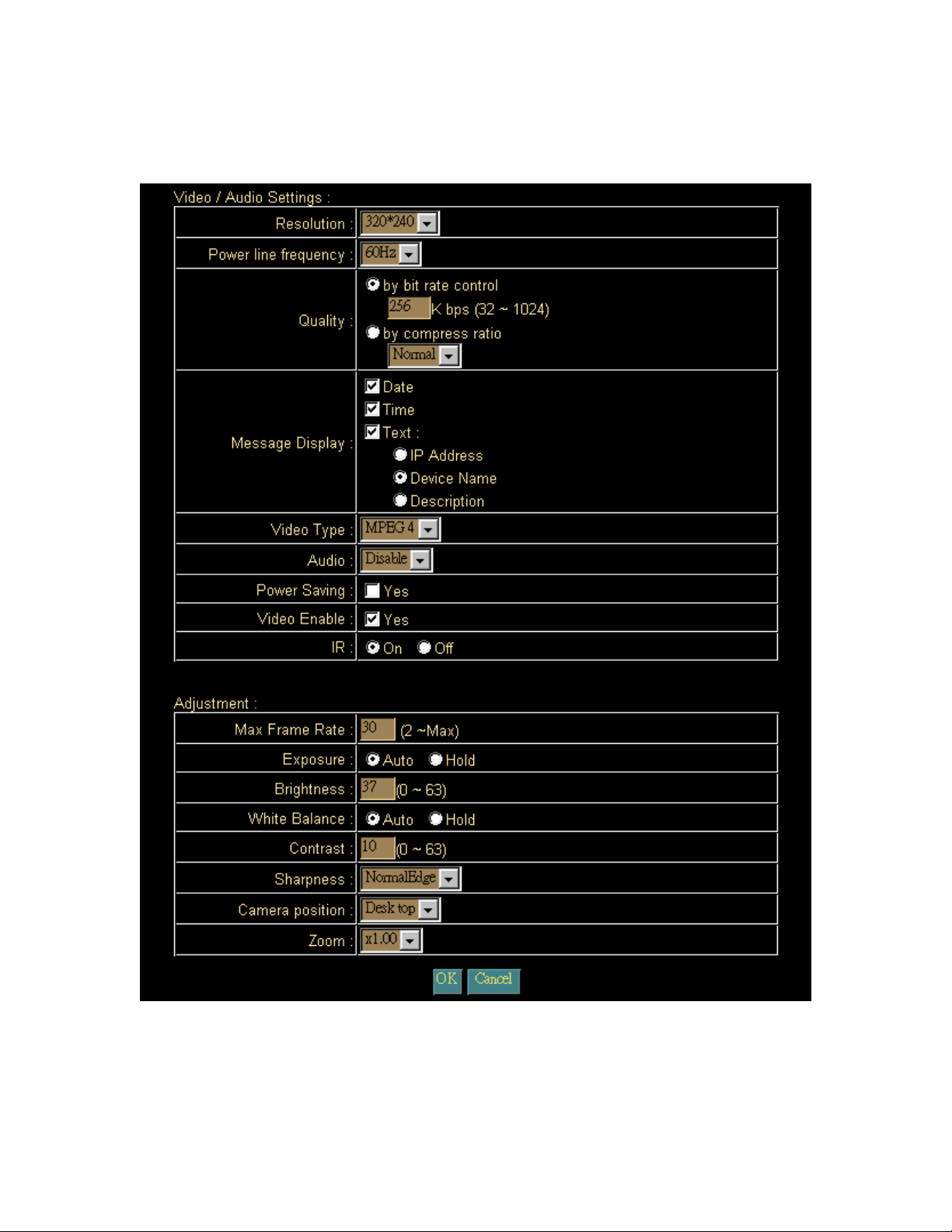
4.2.2.3 Video/Audio:
Adjust Camera parameters
Video / Audio Setting:
- Resolution:
The Network Camera supports 5 kind resolutions:
• 128x96
32/60
Page 33

- Power line frequency:
User should choose either 50 or 60 Hz to meet the power line frequency in your
country.
- Quality:
There are two modes of video quality. User can adjust the video quality by
either bit-rare control or compression ratio:
- Video Output:
The Network Camera supports four kind of video standard. User can choose
one of them to fit to the local video standard.
- Message Display:
You may choose the message that you want to display on the output video.
- Video Type:
The Network Camera supports two kind of video compression mode: MPEG4 or
JPEG. User can choose one of the two compression mode based on
requirement.
- Audio:
The Network Camera supports ADPCM for audio compression.
- Video Enable:
Enable this option will allow stream video to remote clients. Otherwise, the
Network Camera will not stream video out.
- IR:
User can turn on or off the built-in IR LED. This function is very useful under low
illumination environment.
Adjustment:
- Max Frame Rate:
User can set the desired max frame rate to match the limitation of bandwidth or
other requirement.
- Exposure:
Auto: will adjust the internal gain automatically.
• 176x144
• 160x120
• 320x240
• 640x480
• Bit-rate control: from 32kbps to 1024kbps
• Compression ratio:
High: Video is better but frame rate may be slower
Low: Video is poor but frame rate may be higher
Normal: System default value.
33/60
Page 34

Hold: will fix the internal gain.
- Brightness:
Large value will brighten Camera.
- White Balance:
Auto: will adjust the white balance automatically.
Hold: will fix the white balance.
- Contrast:
Large value will contrast Camera heavily.
- Camera Position:
There are three options: Desktop, Ceiling and Mirror.
- Zoom:
The Camera supports smoothly digital zoom in function. The ratio of digital
zoom is varying based on video resolution:
Resolution Zoom
128 x 96 1x 2.23x 3.46x 4x
176 x 144 1x 2.23x 3.46x 4x
160 x 120 1x 2.23x 3.46x 4x
320 x 240 1x 1.33x 1.66x 2x
640 x 480 1x
Select “OK” to save and enable the setting.
4.2.2.4
34/60
Page 35

User:
Setup user name, password and login privilege
There are 3 levels of privilege supported in the Network Camera:
• Admin: This account can do anything in the Network Camera.
• Config: This account can set some parameters of Network Camera.
• View: This account can only view the video stream from the Network Cmaera.
User only can change or modify the username and password of “Administrator”.
You also can set up usernames and passwords for users. The privilege of each user can
be “config” or “view”.
- Live Play Access:
You can set the live play can be access by everyone or just the user who
is in database.
Select “OK” to save and enable the setting.
4.2.2.5
35/60
Page 36

Motion Detection:
Setup motion detection and sensor sensitivity
The motion detection is implemented by a patented software algorithm, it runs on the
Network Camera, due to a larger processing power of motion detection, the overall
performance of Network Camera will be degraded; the frame rate may be reduced.
36/60
Page 37

You can enable or disable motion detection function. If you enable motion detection, you
can also setup detection sensitivity from one of five sensitivity levels.
When alarm was enabled, user can send the captured images to the pre-set E-Mail or
FTP server.
Alert:
- Enable:
You can enable or disable motion detection function.
- Detect Method:
If you enable motion detection, you can also setup detection sensitivity from
one of five sensitivity levels.
- Video Record:
While alerted, the Network Camera can send out the recorded file and images
to pre-defined e-Mail or FTP.
Recording:
- Pre-record time:
The Network Camera can record the video for seconds before alerted. This
function is very useful to know the situation before event happened.
- Record time:
You can choose the duration of the record file.
- Gap to next detect:
You can choose the gap between two events.
E-mail:
- E-Mail To:
E-Mail address of the destination.
- From:
E-Mail address of the source, this Network Camera.
- Subject:
It’s a unique number for each Network Camera for identification.
- Outbound SMTP Server:
The address of SMTP server.
FTP:
- FTP Server:
Type the FTP server name or the IP address of the FTP server to upload still
images and video file.
- Login Name:
37/60
Page 38

Type the user name for the FTP server.
- Password:
Type the password for the FTP server.
Select “OK” to save and enable the setting.
4.2.2.6 Status:
System information, status and log
Status:
User can find out a lot of information about the system such as MAC address, IP
address, firmware version, and so on. User also can get the number of current viewer of
the Network Camera here.
System Log:
User can check the log information of the Network Camera.
38/60
Page 39

4.2.2.7 Factory Default:
Recall the Network Camera factory default setting
The “Factory Default” button will restore to the factory default configuration, all
information changed and saved on the flash will be lost, and restore to the factory default
setting.
You will be prompt before restore to factory default setting.
Select “Factory Default” to continue.
The Network Camera will restore to factory default and reboot again. The Network
Camera be connectable again after 20~30 seconds. Note that the IP address of this
Network Camera will restore to default value: 192.168.0.20.
4.2.2.8 Restart:
Reboot the Network Camera by hardware reset
39/60
Page 40

The “Reboot” button will reboot the Network Camera. It’s useful while the Network
Camera got problem.
You will be prompt before restart the Network Camera.
Select “Restart” to continue.
The Network Camera will reboot and be connectable again after 20~30 seconds.
4.2.1.9 Upgrade:
The Network Camera supports firmware upgrades online. Please contact your dealer for
the latest firmware version. Unzip this firmware file to binary file and store it into your PC.
Then follow the steps as bellows carefully:
1. Close all other application programs which are not necessary for firmware update.
2. Disable “Motion Detection” function.
3. De-select “Video Enable” option.
40/60
Page 41

4. Select “Upgrade”
5. Link to the Firmware Upgrade menu as below:
6. Select the Firmware binary file. (It must be make sure that the Firmware only apply to
the Network Camera, once update, it will be burned into FLASH ROM of system.)
7. Once the firmware file has been selected, select “Upgrade” button to start it.
The upgrade progress status information will be displayed on the screen.
Warning: The download firmware procedure can not be interrupted. If the
41/60
Page 42

power and/or network connection are broken during the download procedure, it
might possibly cause serious damage to the Network Camera. Suggest that do not
upgrade firmware via Wireless LAN due to high error rate possibly.
Please be aware that you should not turn off the power during updating the firmware and
wait for finish message.
Once the upgrading process completed, the Network Camera will reboot the system
automatically.
Note: please wait for 20~30 seconds, and then you can connect to Network Camera
again.
42/60
Page 43

4.3 Capture
You can capture current image and save it to storage media. The image is saved in the
Bitmap format. Click the “Capture” button to save the current display image into the local
PC
If you like to retrieve the saved image, select the file to display it by using any
one of graph editing tools.
Note:
This function is available for logging-in as an administrator only.
43/60
Page 44

4.4 Recording
You can record the current video stream to storage media. The recorded file is saved in
the ASF format.
Press the “Recording” button to start video recording.
After the “Recording” button pressed, it will become
button to stop video recording.
, you can press this
After the stop recording, list the file on the selected saved directory, the file were saved
in ASF format.
The ASF files can be display by the standard Windows Media Player, but it needs the
DixectX 9.0 or higher version to be installed.
Note:
This function is available for logging-in as an administrator only.
44/60
Page 45

Appendix A: Restore Factory Default Settings
There is a switch hidden in the pinhole under the bottom of Network Camera. It is used
to restore the factory default settings. While the Network Camera got problem,
sometimes, restarting the Network Camera will make the system back to a normal state.
In case the system still got problems after reset, user can restore the factory default
settings and install it again.
Restore the Network Camera:
1. Power off the Network Camera.
2. Insert the paper clip or other tool and press and hold the button down
continuously.
3. Power on the Network Camera again.
4. Wait at least 10 seconds and release the tool. Then the Network Camera has
been restored to default settings.
5. Reconfigure the Network Camera
Factory
Default Reset
Note: Restoring the factory default setting will lose the all previous settings forever. User
needs to run the IP Finder program to search the Network Camera and configure it to let
the Network Camera work properly again.
45/60
Page 46

Appendix B: Troubleshooting & Frequently Asked Questions
Question Answer or Resolution
Features
The video and audio
codec is adopted in the
Network Camera.
The maximum number
of users access Network
Camera simultaneously.
The Network Camera
can be used outdoors or
not.
Status LED does not
light up.
The network cabling is
required for the Network
Camera.
The Network Camera
will be installed and work
if a firewall exists on the
network.
The username and
password for the first
time or after factory
default reset
Forgot the username
and password
Forgot the IP address of Check IP address of Network Camera by using the MP4 IP
The Network Camera utilizes MPEG4 and JPEG dual
compression to providing high quality images. MPEG4 is a
standard for video compression and JPEG is a standard for
image compression.
The audio codec is ADPCM compression.
The maximum number of users is 4 clients for video
streaming.
This Network Camera is not weatherproof. It needs to be
equipped with a weatherproof case for outdoors using.
However, equipped with a weatherproof case might disable
the audio function of Network Camera.
Install Network Camera
• Check and confirm that the standard AC adaptor, included
in packaged, is used. Secure the power connector and re
power it on again.
• If the problem is not solved, the Network Camera might be
faulty. Contact your dealer for further help.
The Network Camera uses Category 5 UTP cable allowing 10
and/or 100 Base-T networking.
If a firewall exists on the network, port 80 is open for ordinary
data communication. The Network Camera uses port
80(default) only. This port (or the port you specify from the
Configuration screen if you change the default port) needs to
be opened on the firewall.
Username = admin and Password = admin.
Note that it’s all case sensitivity.
Follow the steps below.
1. Restore the factory default setting by press pressing and
holding down more than 10 seconds when power on
Network Camera.
2. Reconfigure the Network Camera.
46/60
Page 47

the Network Camera. Finder.exe program.
MP4 IP Finder.exe
program cannot find
Network Camera.
• Re power the Network Camera if cannot find the unit within
1 minutes.
• Do not connect Network Camera over a router. MP4 IP
Finder.exe program cannot detect Network Camera over a
router.
• If IP address is not assigned to the PC which running MP4
IP Finder.exe program, then the program cannot find Network
Camera. Make sure that IP address is assigned to the PC
properly.
• Antivirus software on the PC might interfere with the setup
program. Disable the firewall of the antivirus software during
setting up Network Camera.
Internet Explorer does
not seem to work well
with the Network
Camera
Make sure that your Internet Explorer is version 5.5 or later. If
you are experiencing problems, try upgrading to the latest
version of Microsoft’s Internet Explorer from the Microsoft
webpage at: http://www.microsoft.com/windows/ie.
MP4 IP Finder.exe
program fails to save the
network parameters.
Cannot access the login
page and other web
pages of Network
Camera from Internet
Explorer
• Network may have trouble. Confirm the parameters and
connections of the Network Camera.
Access Network Camera
• Maybe the IP Address of the Network Camera is already
being used by another device or computer. To confirm this
possible problem, disconnect the Network Camera from the
network first, and then run the PING utility to check it out.
• Maybe due to the network cable. Try correcting your
network cable and configuration. Test the network interface
by connecting a local computer to the Network Camera via a
crossover cable.
• Make sure the Internet connection and setting is ok.
• Make sure enter the IP address of Internet Explorer is
correct. If Network Camera has a dynamic address, it may
have changed since you last checked it.
• Network congestion may prevent the web page appearing
quickly. Wait for a while.
The IP address and Subnet Mask of the PC and Network
Camera must be in the same class of the private IP address
on the LAN.
• Make sure the http port used by the Network Camera,
default=80, is forward to the Network Camera’s private IP
address.
• The port number assigned in your Network Camera might
not be available via Internet. Check your ISP for available
port.
• The proxy server may prevent you from connecting directly
to Network Camera, set up not to use the proxy server.
• Confirm that Default Gateway address is correct.
• The router needs Port Forwarding feature. Refer to your
47/60
Page 48

router's manual for details.
• Packet Filtering of the router may prohibit access from an
external network. Refer to your router's manual for details.
• Access Network Camera from the Internet with the global IP
address of the router and port number of Network Camera.
• Some routers reject the global IP address to access
Network Camera on the same LAN. Access with the private
IP address and correct port number of Network Camera.
• When you use DDNS, you need to set Default Gateway and
DNS server address.
• If it’s not working after above procedure, reset Network
Camera to default setting and installed it again.
• If the problem is not solved, the Network Camera might be
faulty. Contact your dealer for further help.
Image or video does not
appear in the main page.
The Network Camera
work locally but not
externally.
The unreadable
characters are
displayed.
Frame rate is slower
than the setting.
Blank screen or very
slow video when audio is
enabled.
Image Transfer on • Default Gateway and DNS server address should be set up
• The first time the PC connects to Network Camera, a
pop-up Security Warning window will appear to download
ActiveX Controls. When using Windows NT, Windows 2000
or Windows XP, log on with an appropriate account that is
authorized to install applications.
• Network congestion may prevent the Image screen from
appearing quickly. You may choose lower resolution to
reduce the required bandwidth.
• Might be caused from the firewall protection. Check the
Internet firewall with your system or network administrator.
The firewall may need to have some settings changed in
order for the Network Camera to be accessible outside your
LAN.
• Make sure that the Network Camera isn’t conflicting with
any other web server running on your LAN.
• Check the configuration of the router settings allow the
Network Camera to be accessed outside your local LAN.
Use the operating system of the selected language. Set the
Encoding or the Character Set of the selected language on
the Internet Explorer.
• The traffic of the network and the object of the image affect
the frame rate. The network congestion causes frame rate
slower than the setting.
• When more than one client was viewing, the frame rate
becomes slower.
• Ethernet switching hub can smooth the frame rate especially
in viewing on the Multi-Camera screen.
• Your connection to the Network Camera does not have
enough bandwidth to support a higher frame rate for the
streamed image size. Try reducing the video streaming size
to 160x120 or 320x240 and/or disabling audio.
• Audio will consume 32 kbps. Disable audio to improve
video. Your Internet connection may not have enough
bandwidth to support streaming audio from the Network
Camera.
48/60
Page 49

e-mail or FTP does not
work.
correctly.
• If FTP does not work properly, ask your ISP or network
administrator about the transferring mode of FTP server.
Video Quality of Network Camera
The focus on the
Network Camera is bad.
The color of the image is
poor or strange.
Image flickers. • Wrong power line frequency makes images flicker. Make
Noisy images occur.
How to Reboot the
Network Camera
Can not play the
recorded ASF file
• The lens is dirty or dust is attached. Clean the lens with lens
cleaner. Or adjust the camera focus manually.
• The image may be out of focus, if the object is too near.
Move the object away from Network Camera.
• Adjust White Balance.
• To insure the images you are viewing are the best they can
be, set the Display property setting (color quality) to 16bit at
least and 24 bit or higher if possible within your computer.
•The configuration on the Network Camera image display is
incorrect. You need to adjust the image related parameters
such as brightness and contrast properly.
sure the 50 or 60Hz format of your Network Camera.
The video images might be noisy if the Network Camera is
located in a low light environment. Make the condition around
the Network Camera brighter.
Miscellaneous
If you just want to reboot system without change anything. Go
to Setting page and click Restart linking directly, then system
will reboot again.
Have installed Microsoft®’s DirectX 9.0 or later and use the
Windows Media Player 9 or later to play the ASF filed
recorded by the Network Camera.
49/60
Page 50

Appendix C: PING IP Address
The PING (stands for Packet Internet Groper) command is used to detect whether a
specific IP address is accessible by sending a packet to the specific address and waiting
for a reply. It’s also a very useful tool to confirm Network Camera installed or if the IP
address conflicts with any other devices over the network.
If you want to make sure the IP address of Network Camera, utilize the PING command
as follows:
z Start a DOS window.
z Type ping x.x.x.x, where x.x.x.x is the IP address of the Network Camera.
The replies, as illustrated below, will provide an explanation to the problem.
If you want to detect any other devices conflicts with the IP address of Network Camera,
also can utilize the PING command but you must disconnect the Network Camera from
the network first.
50/60
Page 51

Appendix D: Bandwidth Estimation
The frame rate of video transmitted from the Network Camera depends on connection
bandwidth between client and server, video resolution, and quality setting of server.
Here is a guideline to help you roughly estimate the bandwidth requirements form your
Network Camera.
The required bandwidth depends on content of video source. The slow motion video will
produce smaller bit rate generally and fast motion will produce higher bit rate vice versa.
Actual results generated by the Network Camera may be varying.
Image Resolution Average range of Data
Sizes for JPEG mode
160 x 120 (QQVGA) 3 ~ 6k byte per frame 100kbps~256kbps @ 30fps
320 x 240 (QVGA) 8 ~ 20k byte per frame 300kbps~600kbps @ 30fps
640 x 480 (VGA) 20 ~ 50K byte per frame 400kbps~1000kbps @ 12fps
Note: Audio streaming will take bandwidth around 32 kbps. Most
ADSL/Cable modem upload speeds may not even reach up to 128 kbps.
Thus, you may not be able to receive any video while streaming audio on a
128 kbps or lower connection. Even though the upload speed is more than
128kbps, for optimal video performance, disabling audio streaming will get
better video performance.
Average bit rate for MPEG4
mode
51/60
Page 52

Appendix E: Specifications
Model Network Camera
Control Interface
Operating Humidity
Operating Temperature
Power Consumption
Power Supply
Dimension
Camera Module
Image Pick-up Device
Effective Picture Elements
S/N Ratio
Auto Exposure
Auto White Balance
Camera Position
Power Line Frequency
Internet Explorer or Multi-channel software player
10% ~ 80%
5°C to 40°C
4W max. (WLAN model and IR LEDs on)
5V DC ± 10%
Main body: 100*62mm (DXH)
1/4“ Micron CMOS image sensor
640*480 (H*V)
More than 45 dB
Yes
Yes
Desktop / Ceiling /Mirror
50 / 60 Hz
Sharpness
IP Module
Codec
Resolution
Frame Rate
Audio Streaming
Compatibility
LAN I/F
RAM
Flash
Image Storing Memory
52/60
Up to 30fps for QQVGA and QVGA resolutions
Strong / Normal / Soft
MPEG4 and MJPEG, 3 levels
640*480, 320*240, 162*120
Up to 12fps for VGA resolution
Yes
Windows 2000, XP and above
10/100M
64Mb SDRAM
16Mb NOR Flash Memory
By RAM
Page 53

Operating System
eCos
Type Of IP Address Needed
Notification
Firmware Upgrade
Security
Viewer
Digital zoom
Networking Protocol
Statistic or Dynamic
Email, FTP
Via Ethernet
3 Levels
Microsoft® Internet Explorer 5.5 or later
400% (Maximum)
TCP/IP, HTTP, SMTP, FTP, NTP, DNS, DDNS, ARP and
DHCP, UPnP
53/60
Page 54

Appendix F: Time Zone Table
GMT stands for Greenwich Mean Time which is the global time that all time zones are
measured from.
54/60
Page 55

55/60
Page 56

Appendix G: DDNS Application
1. Preface
If you have a Cable modem, xDSL, ISDN or Dialup, this is a great way to host your
own Network Camera. Get your own domain like www.yourname.com*,
www.yourname.com.tw* etc. (Note: This domain must be registered via registration
authorities such as Network Solutions, DirectNIC, Register.com etc). Your domain
name's dynamic IP address is automatically tracked by a DDNS server.
Host your own Network Camera and much more no matter what your computer's IP
address may be and even if you have dialup, DSL or cable modem internet
connection where your computer's IP address changes all the time!! DDNS service
supports all top level domain names including but not limited
to .com, .net, .org, .to, .uk etc.
2. Ethernet Network Environment
Normally, a DDNS service is only necessary for the users that could only obtain
dynamic IP addresses. As to the users that could obtain the static valid IP address,
they do not usually have to apply the DDNS service. Before we decide if DDNS is
necessary for the users, we have to check what kind of Ethernet network
environment we have to install our Network Camera on.
(1) Environment of Fixed Valid IP Network
If users could obtain valid IP addresses, they could save the effort to apply DDNS
service. Because the IP address in this environment is fixed, users could input
the IP address or domain name of demo site directly in the IE browser.
(2) Environment of Dynamic IP Network
If users is under an environment of dynamic IP network (Dial-up ADSL), they
have to apply a domain name in advance. Then apply DDNS service. Finally
setup the necessary information of DDNS of the Network Camera in order to let
the outside administrator be able to access through internet.
3. Application Steps—DDNS & Domain Name
(1). Visit the following web site: http://www.dyndns.org/ (Pink No.1)
(2). Click “Account” (Pink No. 2)
56/60
Page 57

(3). After the columns show up at the left side, click “Create Account”.
(4). Fill the application agreement and necessary information.
a. Input Name
b. E-mail input and confirmation
c. Password input and confirmation
d. Submit all the input information and finish creating a account
57/60
Page 58

(5). Check your e-mail mailbox. There will be an e-mail with a title “Your
DynDNS.org Account Information “. Click the hyperlink address to confirm the
DDNS service that you just applied. Then DDNS you applied activated.
58/60
Page 59

(6). Enter the web page http://www.dyndns.org/ again. Input your username and
password that you just applied to login administration interface of DDNS service.
(7). If the correct username and password are input, you can see the following picture at the
top-right of the login page.
(8). Click the “Services”.
(9). Click the “ Dynamic DNS ” and then click the “Add a host”.
59/60
Page 60
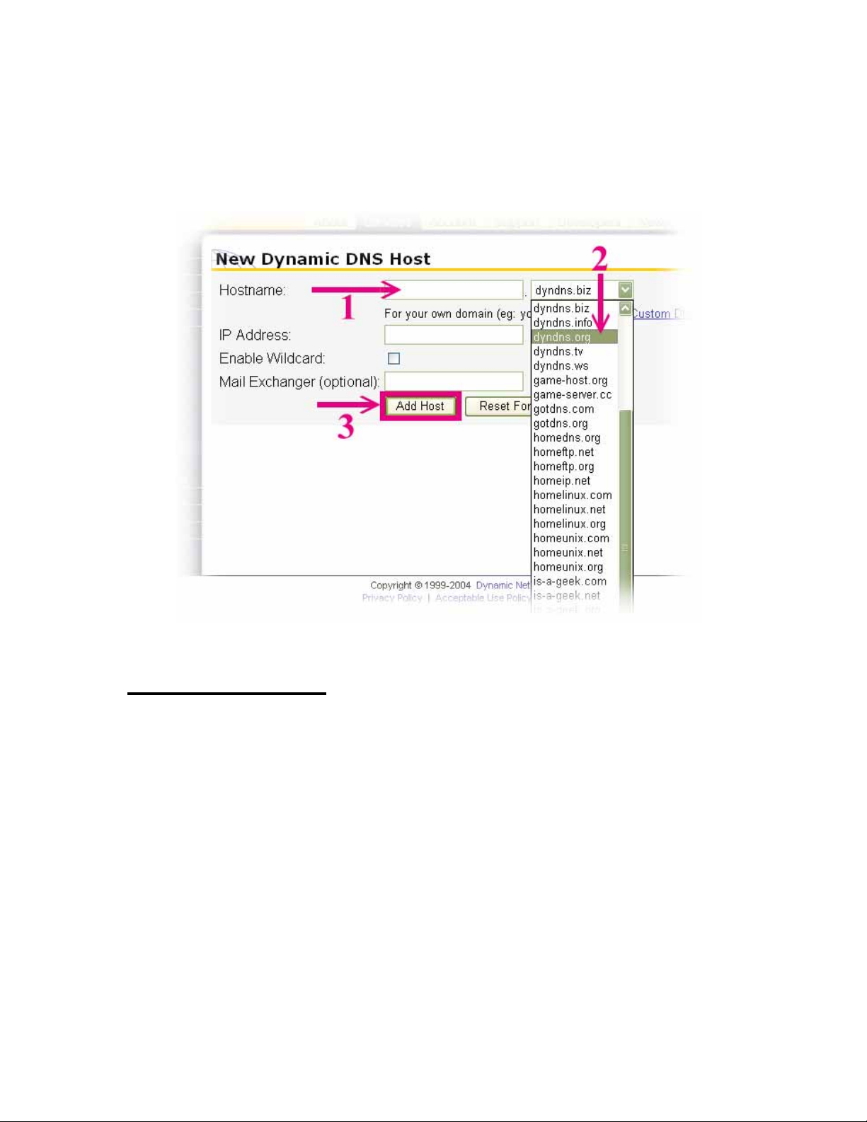
(10). We could create a domain name without any charge at this step. First, we
input the host name. (Pink No.1) Then we pick a domain that is easy to remember.
(Pink No.2) Finally, click the “Add Host” to submit the domain name information.
(Pink No.3)
4. Setup the DDNS
At last, users have to enter the web page of Network Camera and setup the necessary
information of DDNS after the application of DDNS service. Please check the user
manual to access the DDNS pages. After saving the modification, restart the device. The
external users could browse the Network Camera by the input of their domain name.
60/60
 Loading...