

Page 1
24-Port 10/100/1000Mbps with 16-Port SFP
Web Smart Ethernet Switch
GSW-2416SF
User’s Manual
- 1 -
Page 2

Trademarks
Copyright © PLANET Technology Corp. 2006.
Contents subject to revision without prior notice.
PLANET is a registered trademark of PLANET Technology Corp. All other trademarks belong to their respective
owners.
Disclaimer
PLANET Technology does not warrant that the hardware will work properly in all environments and applications,
and makes no warranty and representation, either implied or expressed, with respect to the quality, performance,
merchantability, or fitness for a particular purpose.
PLANET has made every effort to ensure that this User’s Manual is accurate; PLANET disclaims liability for any
inaccuracies or omissions that may have occurred.
Information in this User’s Manual is subject to change without notice and does not represent a commitment on the
part of PLANET. PLANET assumes no responsibility for any inaccuracies that may be contained in this User’s
Manual. PLANET makes no commitment to update or keep current the information in this User’s Manual, and
reserves the right to make improvements to this User’s Manual and/or to the products described in this User’s
Manual, at any time without notice.
If you find information in this manual that is incorrect, misleading, or incomplete, we would appreciate your
comments and suggestions.
FCC Warning
This equipment has been tested and found to comply with the limits for a Class A digital device, pursuant to Part
15 of the FCC Rules. These limits are designed to provide reasonable protection against harmful interference
when the equipment is operated in a commercial environment. This equipment generates, uses, and can radiate
radio frequency energy and, if not installed and used in accordance with the Instruction manual, may cause
harmful interference to radio communications. Operation of this equipment in a residential area is likely to cause
harmful interference in which case the user will be required to correct the interference at his own expense.
CE Mark Warning
This is a Class A product. In a domestic environment, this product may cause radio interference, in which case the
user may be required to take adequate measures.
WEEE Warning
To avoid the potential effects on the environment and human health as a result of the presence of
hazardous substances in electrical and electronic equipment, end users of electrical and electronic
equipment should understand the meaning of the crossed-out wheeled bin symbol. Do not dispose of
WEEE as unsorted municipal waste and have to collect such WEEE separately.
Revision
PLANET 24-Port 10/100/1000Mbps with 16-Port SFP Web Smart Ethernet Switch User's Manual
FOR MODEL: GSW-2416SF
REVISION: 1.0 (JUNE.2006)
Part No.: EM_GSW2416SFV1 (2080-A82050-000)
EM-GSW2416SFv1 - 2 -
Page 3

TABLE OF CONTENTS
1. INTRODUCTION ......................................................................................................................................................4
1.1 CHECKLIST................................................................................................................................................................4
1.2 ABOUT THE SWITCH..................................................................................................................................................4
1.3 FEATURES.................................................................................................................................................................4
1.4 SPECIFICATION..........................................................................................................................................................5
2. HARDWARE DESCRIPTION..................................................................................................................................6
2.1 FRONT PANEL ........................................................................................................................................................... 6
2.2 REAR PANEL .............................................................................................................................................................6
2.3 HARDWARE INSTALLATION.......................................................................................................................................7
3. SWITCH MANAGEMENT.......................................................................................................................................9
3.1 OVERVIEW................................................................................................................................................................9
3.2 MANAGEMENT METHODS .........................................................................................................................................9
3.2.1 Local Console Management .............................................................................................................................9
3.2.2 Web Management ...........................................................................................................................................10
3.3 ASSIGNING AN IP ADDRESS TO THE SWITCH ...........................................................................................................10
3.4 LOGGING ON TO THE GSW-2416SF........................................................................................................................11
4. CONSOLE INTERFACE ........................................................................................................................................12
4.1 CONNECT TO PC.................................................................................................................................................12
4.2 LOGIN IN.................................................................................................................................................................13
4.3 MAIN MENU SCREEN...............................................................................................................................................13
4.4 GETTING STARTED..................................................................................................................................................14
4.4.1 General Guidelines.........................................................................................................................................14
4.4.2 Show command...............................................................................................................................................15
4.4.3 Set command...................................................................................................................................................22
4.4.4 Factory default................................................................................................................................................30
4.4.5 Reboot.............................................................................................................................................................31
4.4.6 Logout.............................................................................................................................................................32
4.5 FIRMWARE UPDATE ................................................................................................................................................33
5. WEB MANAGEMENT.............................................................................................................................................35
5.1 LOGIN IN TO THE SWITCH........................................................................................................................................35
5.2 PORT CONFIG..........................................................................................................................................................36
5.3 VLAN SETUP..........................................................................................................................................................38
5.3.1 VLAN Group and member settings.................................................................................................................38
5.3.2 VLAN setting example: ...................................................................................................................................39
5.4 PORT TRUNK SETUP................................................................................................................................................43
5.5 STATUS ...................................................................................................................................................................45
5.5.1 Port Status.......................................................................................................................................................45
5.5.2 Statistics..........................................................................................................................................................45
5.6 MISC CONFIGURATION............................................................................................................................................47
5.6.1 System Setup ...................................................................................................................................................47
5.7 TOOLS.....................................................................................................................................................................48
5.7.1 Reboot.............................................................................................................................................................48
5.7.2 Factory Reset..................................................................................................................................................49
5.8 LOGOUT..................................................................................................................................................................50
6. SWITCH OPERATION............................................................................................................................................51
6.1 ADDRESS TABLE.....................................................................................................................................................51
6.2 LEARNING...............................................................................................................................................................51
6.3 FORWARDING & FILTERING ....................................................................................................................................51
6.4 STORE-AND-FORWARD ...........................................................................................................................................51
6.5 AUTO-NEGOTIATION...............................................................................................................................................51
7.TROUBLESHOOTING.............................................................................................................................................52
APPENDIX A NETWORKING CONNECTION.......................................................................................................53
A.1 SWITCH‘S RJ-45 PIN ASSIGNMENTS.......................................................................................................................53
A.2 1000MBPS, 1000BASE-T .......................................................................................................................................53
A.3 RJ-45 CABLE PIN ASSIGNMENT...............................................................................................................................53
EM-GSW2416SFv1 - 3 -
Page 4

1. INTRODUCTION
1.1 Checklist
Check the contents of your package for follow i ng parts:
z GSW-2416SF x1
z User's manual CD x1
z Quick installation guide x1
z Power cord x 1
z RS232 cable x1
z Rubber feet x 4
z Two rack-mounting brackets with attachment screws x1
If any of these pieces are missing or damaged, please contact your dealer immediately, if possible, retain the carton
including the original packing material, and use them against to repack the product in case there is a need to return it to
us for repair.
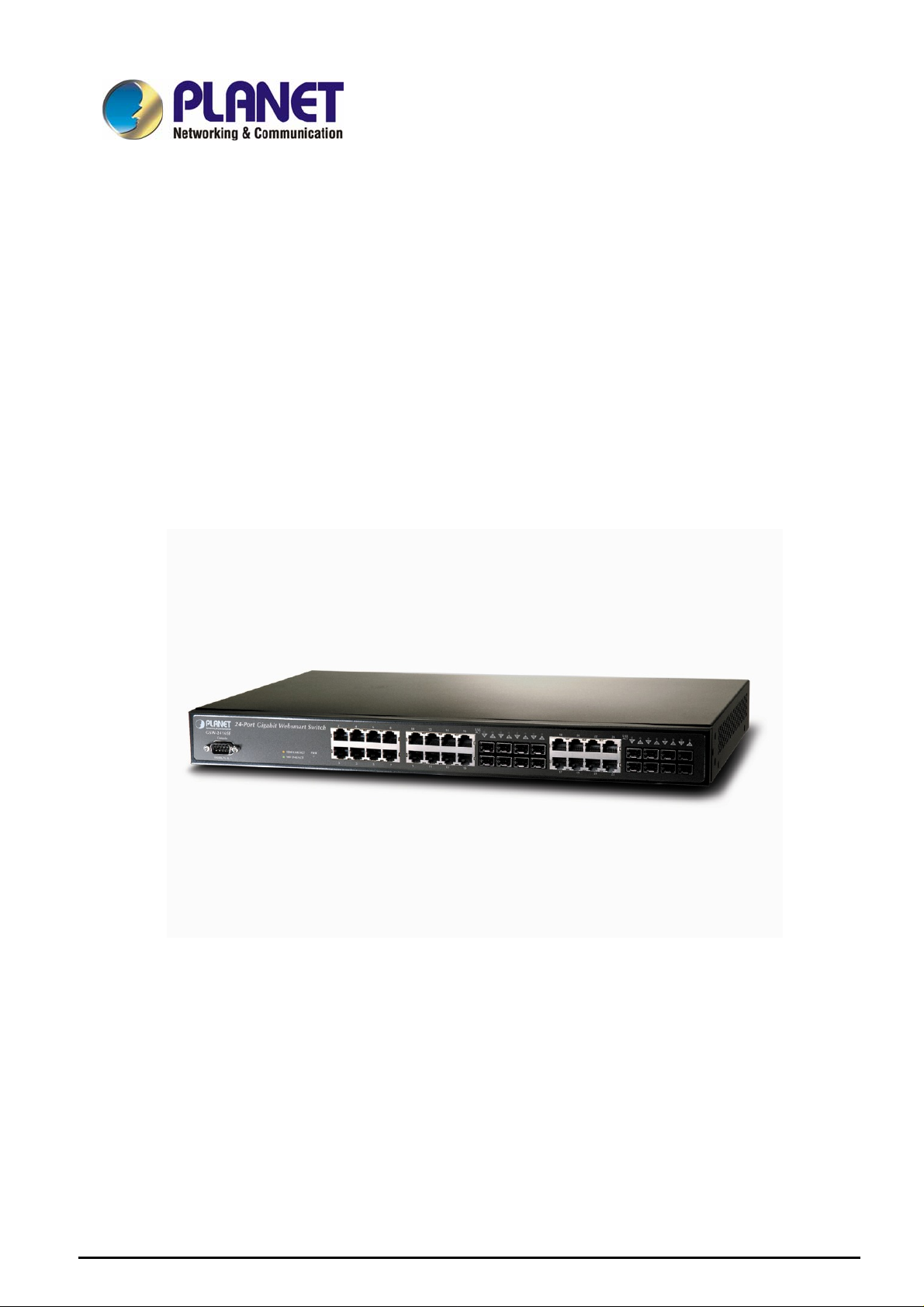
1.2 About the Switch
The PLANET GSW-2416SF is a 24-Port 10/100/1000Mbps Web Smart non-blocking wire-speed performance Ethernet
Switch. With a 48Gbps internal switching fabric, the Switch can handle extremely large amounts of data in a secure
topology linking to a backbone or high capacity servers. The GSW-2416SF could recognize up to 8K MAC Address table
and provides 400KB on-chip frame buffer. They offer wire-speed packet transfer performance without risk of packet loss.
With high data throughput, the GSW-2416SF provides the most convenient for user to upgrade their network to Gigabit
environment.
All RJ-45 copper interfaces support 10/100/1000Mbps Auto-Negotiation for optimal speed detection through RJ-45
Category 6, 5 or 5e cables. Also, all the ports support Auto-MDI/MDI-X that can automatically detect the type of
connection to any Ethernet device without requiring special straight or crossover cables. 24-Port TP by default and
together with 16-SFP (Small Form-factor Pluggable), shared with port#9 to port #24, make the switch be a 16-Port
Gigabit Fiber Switch with mini GBIC fiber-optic module installed that shall provide long distance fiber connectivity.
The GSW-2416SF provides Smart management functions through the Web management interface. Functions such as
per port speed, duplex, IEEE 802.3x flow-control settings and 802.1p QoS settings, Trunking and Port-Base VLAN, all
can be found in the friendly user interface of your web browser. These features provide a cost-effective way to manage
the devices from Internet whenever you are at work or at home.
1.3 Features
◆ Complies with IEEE 802.3, 10Base-T, IEEE 802.3u, 100Base-TX and IEEE 802.3ab, 1000Base-T, IEEE 802.3z,
1000Base-SX/LX Ethernet standard
◆ 24-Port 10/100/1000Mbps Ethernet ports
◆ 16-Port SFP (Small Form-factor Pluggable) for 3.3V mini GBIC module, shared with port#9 to #24
◆ Features Store-and-Forward mode with wire-speed filtering and forwarding rates
◆ Hardware based 10/100Mbps, half/full duplex and 1000Mbps full duplex mode, flow control and auto-negotiation
◆ IEEE 802.3x flow control for full duplex operation and backpressure for half duplex operation
◆ Integrated address look-up engine, support 8K absolute MAC addresses
◆ Remote Web management interface
◆ 9K Jumbo frame support
◆ Port-based VLAN, Port Trunk, QoS support
◆ Automatic address learning and address aging
◆ Supports Auto-MDI/MDI-X function
EM-GSW2416SFv1 - 4 -
Page 5

◆ Support CSMA/CD protocol
◆ 100~240VAC, 50~60Hz universal Power input
◆ FCC, CE class A compliant
1.4 Specification
Model GSW-2416SF
10/100/1000Base-T Ports
SFP Ports
LED Display One power,
Console DB-9 RS-232
Switch architecture Store and forward
MAC address 8K MAC address table with Auto learning function
Switch fabric 48Gbps
Throughput 35.7Mpps
Flow Control
Jumbo Frame
Management Console / web management interfaces
IEEE 802.1p Port priority Allow to assign low and high priority on each port
Port Trunk Three trunk groups with up to 4-port per trunk
VLAN Up to 24 port-based VLAN
Management VLAN Yes
Power AC 100~240V, 50/60Hz,
Power consumption Max. 130 watts, 443 BTU/hr
Temperature
Humidity
Dimension (W x D x H) 440 x 200 x 44 mm (1U height)
EMI FCC Part 15 Class A, CE
Standard Compliance
24 port RJ-45
10/100/1000Mbps, Auto Negotiation, Auto-MDI/MDI-X
16 port 3.3VC mini-GBIC SFP
1000Mbps full-duplex; shared with port#9 to ort 24
1-24 port RJ-45, LNK/ACT,
9-16 port SFP (mini-GBIC),LNK/ACT
Back pressure for half duplex,
IEEE 802.3x Pause Frame for full duplex
Up to 9KB
Operating: 0~50 degree C, Storage -40~70 degree C
Operating:10% to 90%, Storage: 5% to 95% (Non-condensing)
IEEE 802.3 (Ethernet)
IEEE 802.3u (Fast Ethernet)
IEEE 802.3ab(Gigabit Ethernet)
IEEE 802.3z (Gigabit Ethernet, 1000Base-SX/LX)
IEEE 802.3x (Flow control)
IEEE 802.1p QoS
EM-GSW2416SFv1 - 5 -
Page 6
2. HARDWARE DESCRIPTION
This product provides both Copper and Fiber connecter at same switch – 24 Ports TP and 16 Ports SFP (shared with Port
#9 to 24), and automatically distinguishes the speed of incoming connection.
This section describes the hardware features of GSW-2416SF. For easier management and control of the Switch,
familiarize yourself with its display indicators, and ports. Front panel illustrations in this chapter display the unit LED
indicators. Before connecting any network device to the GSW-2416SF, read this chapter carefully.
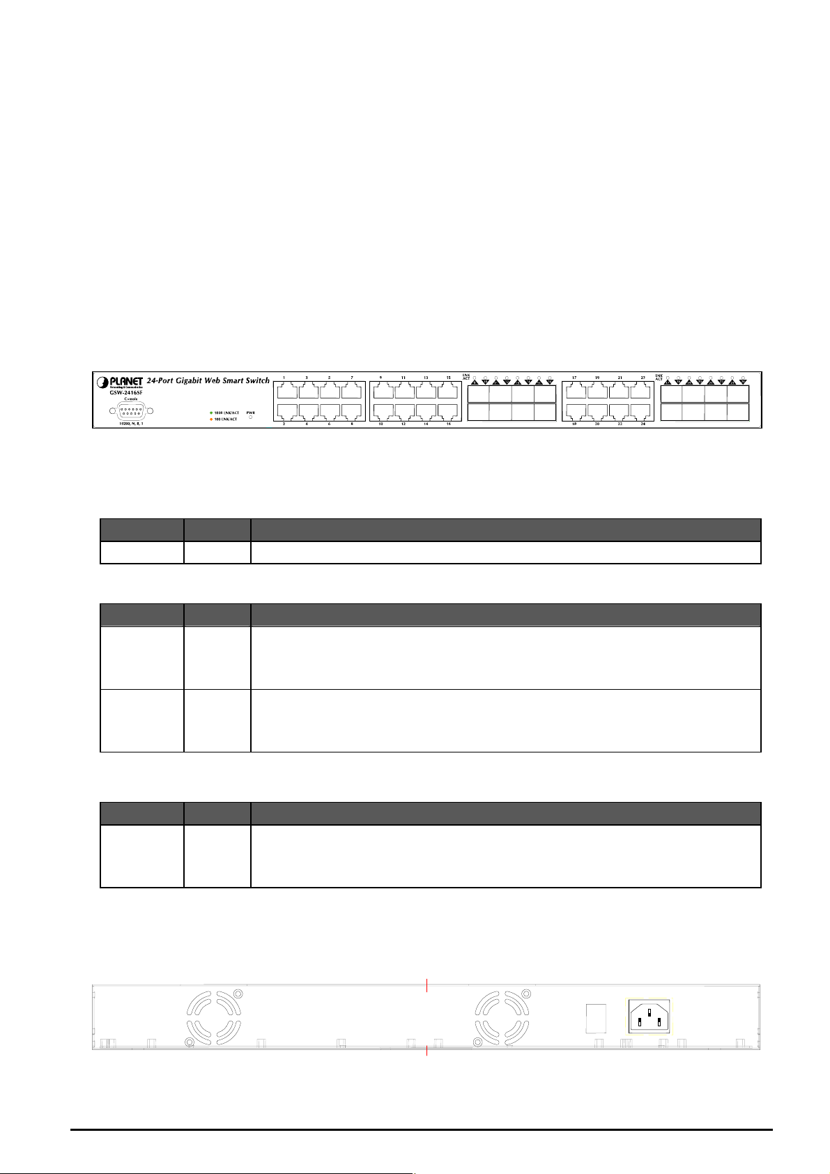
2.1 Front Panel
The Front Panel of the GSW-2416SF Web Smart Ethernet Switch consists of 24x Auto-Sensing 10/100/1000Mbps
Ethernet RJ-45 Ports and 16x SFP(Small Form-factor Pluggable) Ports. The LED Indicators are also located on the front
panel of the GSW-2416SF. And one console port at Front panel for switch management.
Figure 2-1: GSW-2416SF Switch front panel
2.1.1 LED indicators
System
LED Color Function
PWR Green Lights to indicate that the Switch has power.
Per 10/100/1000Mbps port
LED Color Function
1000
Green
LNK/ACT
100
Amber
LNK/ACT
Lights to indicate that the Switch is successfully connecting to the network at
1000Mbps.
Blinks to indicate the Switch is receiving or sending data.
Lights to indicate that the Switch is successfully connecting to the network at
100Mbps.
Blinks to indicate the Switch is receiving or sending data.
Per SFP Interface
LED Color Function
SFP
Green
LNK/ACT
Lights to indicate that the Switch is successfully connecting to the network at
1000Mbps through SFP interface.
Blinks to indicate the Switch is receiving or sending data.
2.2 Rear Panel
The rear panel of the GSW-2416SF indicates an AC inlet power socket, which accepts input power from 100 to 240V AC,
50-60Hz, and 1A max. And one I/O power switch at rear panel for power management.
100~240V
ON
OFF
POWER
Figure 2-2: GSW-2416SF Switch rear panel
EM-GSW2416SFv1 - 6 -
AC
50/60H
z
Page 7

Power Notice:
1. The device is a power-required device, it means, it will not work till it is powered. If your networks should active all the
time, please consider using UPS (Uninterrupted Power Supply) for your device. It will prevent you from network data
loss or network downtime.
2. In some area, installing a surge suppression device may also help to protect your GSW-2416SF from being damaged by
unregulated surge or current to the GSW-2416SF.
2.3 Hardware Installation
This part describes how to install your Web Smart Ethernet Switch and make connections to the Switch. Please read
the following topics and perform the procedures in the order being presented. To install your Switch on a desktop or
shelf, simply completed the following steps.
2.3.1 Desktop Installation
To install a Switch on a desktop or shelf, simply completed the following steps:
Step 1: Attached the rubber feet to the recessed areas on the bottom of the Switch.
Step 2: Place the Switch on a desktop or shelf near an AC power source.
Step 3: Keep enough ventilation space between the Switch and the surrounding objects.
#Notice:
When choosing a location, please keep in mind the environmental restrictions discussed in Chapter 1, Section 4,
Specification.
Step 4: Connect your Switch to network devices.
A. Connect one end of a standard network cable to the 10/100/1000 RJ-45 ports on the front of the GSW-2416SF
Switch.
B. Connect the other end of the cable to the network devices such as printer servers, workstations or routers…etc.
#Notice:
Connection to the Switch requires UTP Category 5/5e/6 network cabling w ith RJ-45 tips. For more information, please
see the Cabling Specification in Appendix A.
Step 5: Supply power to the Switch.
A. Connect one end of the power cable to the Switch.
B. Connect the power plug of the power cable to a standard wall outlet then power on the Switch.
When the Switch receives power, the Power LED should remain solid Green.
2.3.2 Rack Mounting
To install the Switch in a 19-inch standard rack, follow the instructions described below.
Step 1: Place your Switch on a hard flat surface, with the front panel positioned towards your front side.
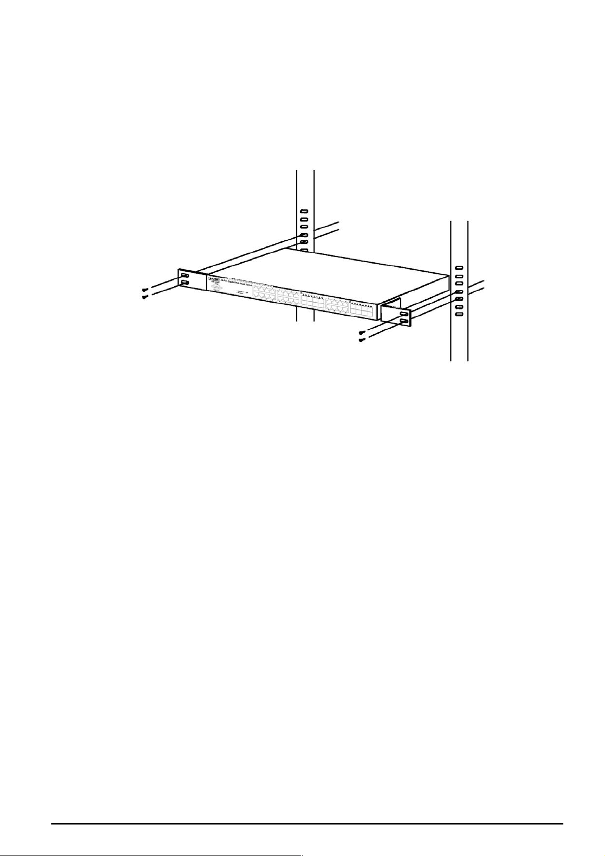
Step 2: Attach a rack-mount bracket to each side of the Switch with supplied screws attached to the package. Figure
2-3 shows how to attach brackets to one side of the Switch.
Figure 2-3 Attaching the brackets to the Switch
EM-GSW2416SFv1 - 7 -
Page 8
Caution:
You must use the screws supplied with the mounting brackets. Damage caused to the parts by using incorrect screws
uld invalidate your warranty.
wo
Step 3: Secure the brackets tightly.
Step 4: Follow the same steps to attach the second bracket to the opposite side.
tep 5: After the brackets are attached to the Switch, use suitable screws to securely attach the brackets to the rack, as
S
shown in Figure 2-4.
Step 6: Proceed w
supply power to your Switch.
Figure 2-4 Mounting the Switch in a Rack
ith the steps 4 and steps 5 of section 2.3.1 Desktop Installation to connect the network cabling and
EM-GSW2416SFv1 - 8 -
Page 9
3. SWITCH MANAGEMENT
This chapter describes how to m
- Overview
- Management methods
- Assigning an IP address to the GSW-2416SF
- Log
ging on to the GSW-2416SF
anage the GSW-2416SF. Topics include:
3.1 Overview
This chapter gives an overview of switch management. The GSW-2416SF provides a user-friendly, command line under
console interface and Simply WEB browser interface. Using these interfaces, you can perform various switch
configuration and management activities, including:
z Port configuration
z VLAN Add/Remove/Assign
z Flow Control Enable/Disable
z Port Trunk Create/Assign ( WEB GUI supported )
z System IP address setting.
z Management account and password setting.
z Port status/static monitoring
z System reboot and reload factory default.
Please refer to the following Chapter 4 and 5 for the details.
3.2 Management Methods
There are two ways to manage the GSW-2416SF:
- Local Console Management via the Switch serial port.
- Web Management via a network or dial-up connection.
3.2.1 Local Console Management
You can manage the GSW-2416SF locally by connecting a VT100 terminal, or a personal computer or workstation with
terminal emulation software, to the Switch serial port. The terminal or workstation connects to the Sw itch serial port using a
null modem cable that has the appropriate connectors on each end.
This management method is ideal when:
- The network is unreliable.
- The Network Manager does not have direct network connection.
The serial port of the Switch default setting is set to 19200 baud using a character format of 8 data bits, no parity, and 1
stop bit.
Therefore, configure the terminal or workstation to use these settings before you log on to the GSW-2416SF. You can
change this default setting, if desired, after you log on.
EM-GSW2416SFv1 - 9 -
Page 10
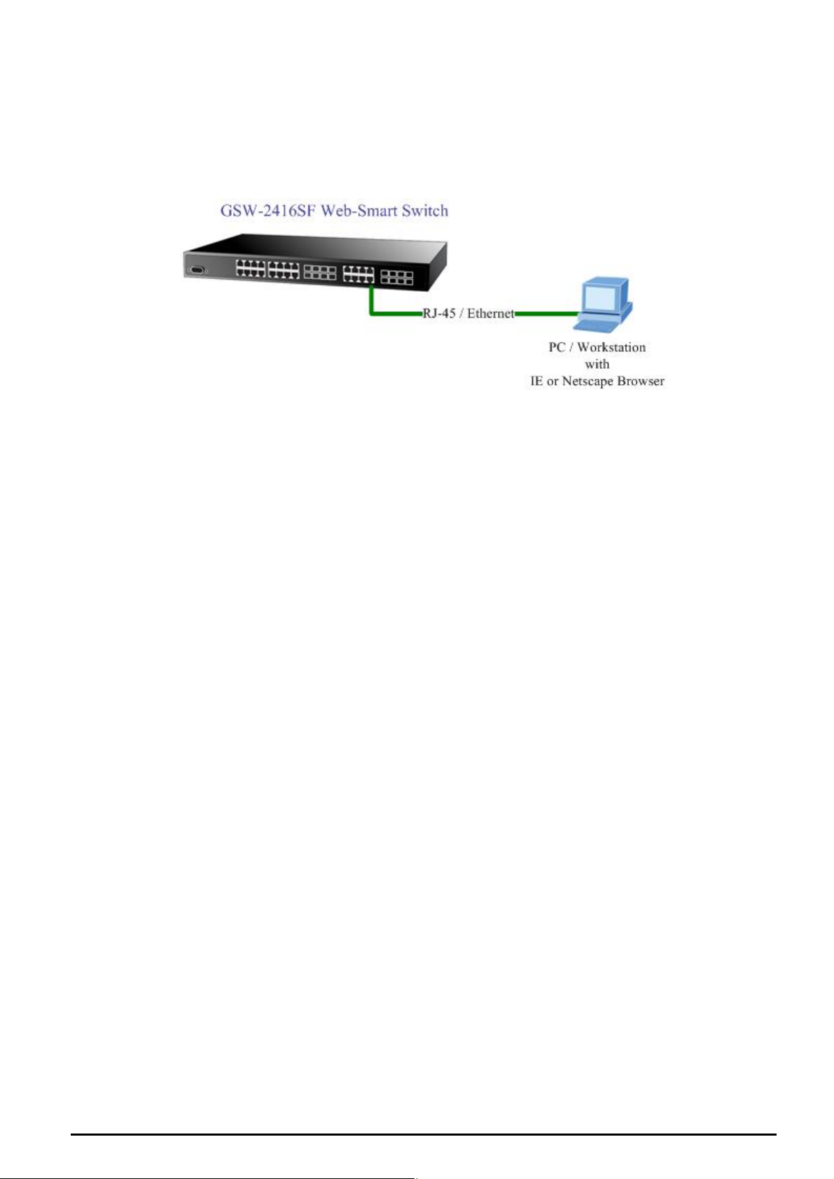
3.2.2 Web Management
You can manage the GSW-2416SF remotely by having a remote host with w
Explorer or Netscape Navigator.
Using this management method:
The GSW (IP) address accessible for the remote host.
3.3 Assigning an IP Address to the Sw
To m owser with a Management Station, you must assign an IP
addr to
To se xx mmm.mmm.mmm.mmm ggg.ggg.ggg.ggg” command. For
example, to configure the switch with the following IP settings
-2416SF must have an Internet Protocol
itch
anage the GSW-2416SF remotely through the web br
ess the GSW-2416SF.
t the IP address, please use “set ip xxx.xxx.xxx.x
:
eb browser, such as Microsoft Internet
IP Address: 192.168.0.100
Subnet Mask: 255.255.255.0
Default Gateway: 192.168.0.254
Press the following command and press <Enter>
set ip 192.168.0.100 255.255.255.0 192.168.0.254
If the IP is successfully configured, the switch will apply the new IP address setting immediately. You can access the web
interface of GSW-2416SF through the new IP address.
EM-GSW2416SFv1 - 10 -
Page 11
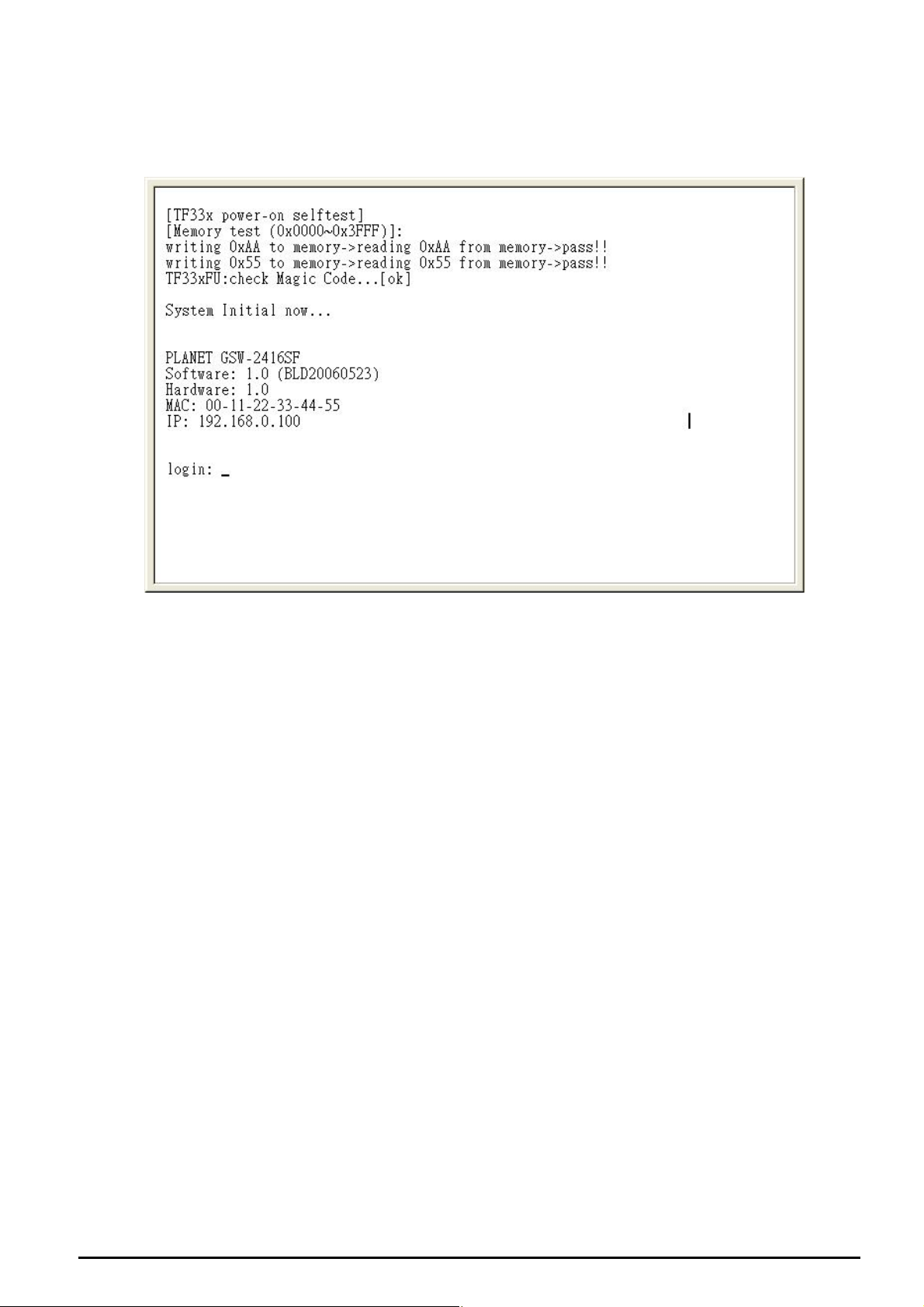
3.4 Logging on to the GSW-2416SF
When you log on to the GSW-2416SF console port for the first time, a sign-on string appears and you are prompted
console login user name and pass
word.
for a
The me is admin without password.
factory default login userna
#
Notice:
1. e and memorize the new password after this first setup.
For security reason, please chang
2. nsole interface.
Only accept command in lowercase letter under co
EM-GSW2416SFv1 - 11 -
Page 12
4. CONSOLE INTERFACE
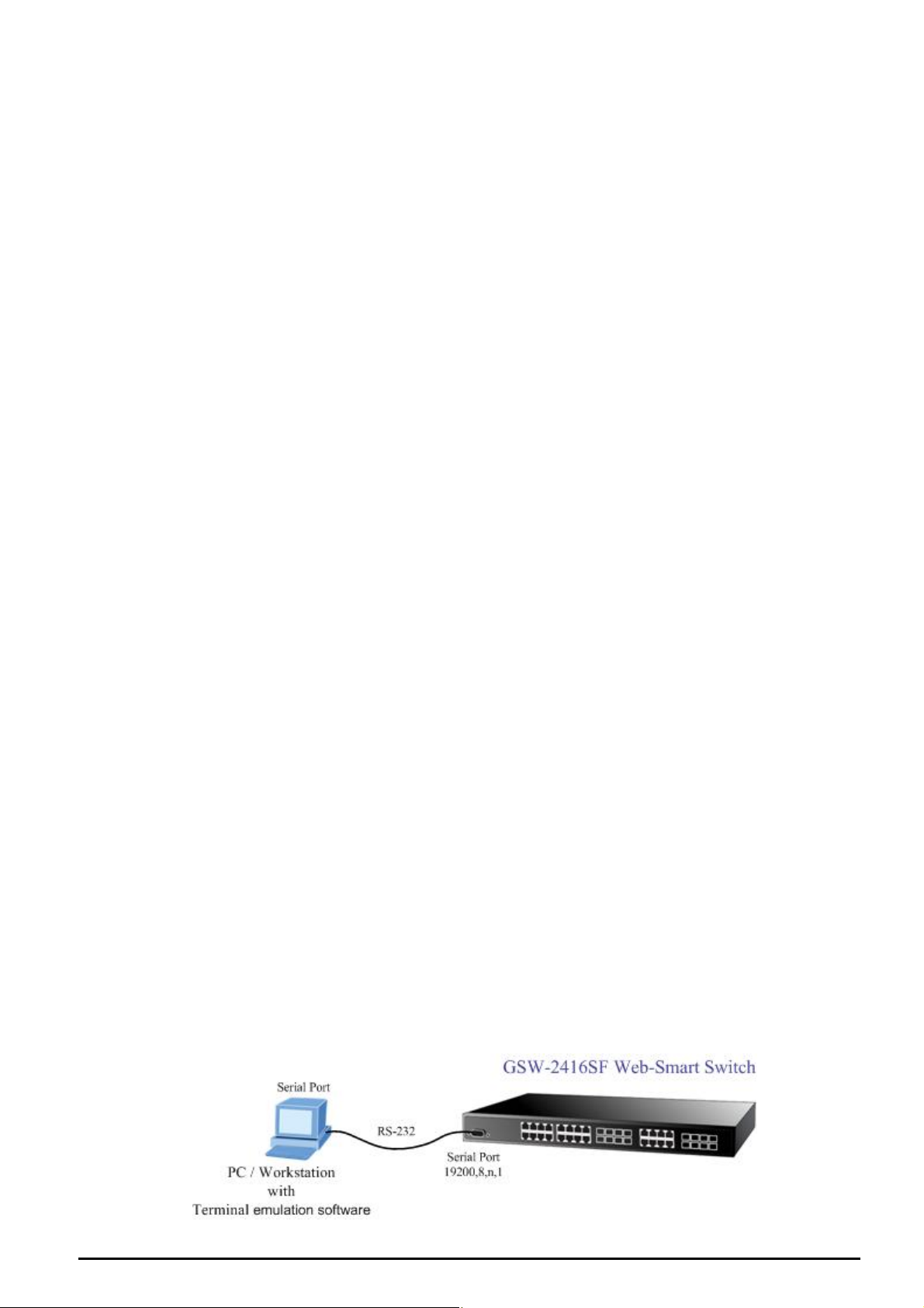
4.1 CONNECT TO PC
RS-232 serial cable
Use the bundled RS-232 serial cable and attach the 9-pin female connector to the male connector on the
GSW-2416SF. Plug the other side of this cable to your PC.
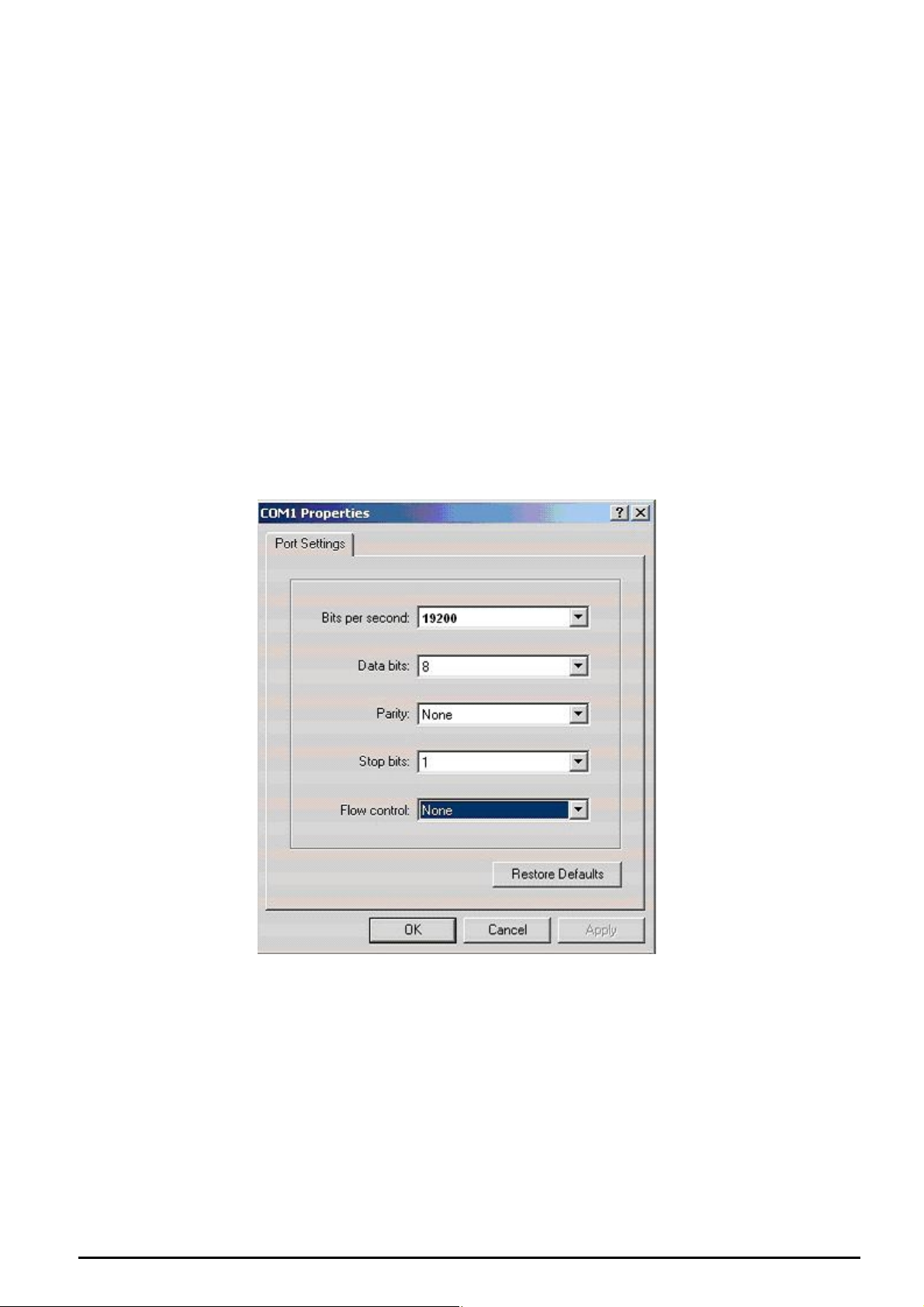
Hyper Terminal
In Windows 98/2000/ME/XP, launch “HyperTerminal”, create a new connection, and adjust settings as below:
Emulation: VT-100 compatible
Baud per second: 19200
Data bits: 8
Parity: None
Stop bits: 1
Flow Control: None
To gain a demo, please see the Figure 4-1.
Figure 4-1 Port Settings for console interface
EM-GSW2416SFv1 - 12 -
Page 13
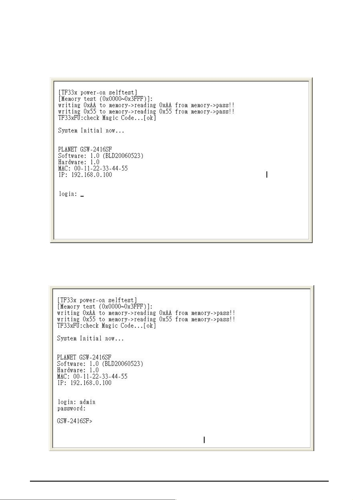
4.2 Login in
Login is required to access the console interface after the self-test completes successfully. The factory default user name
is "admin" without password. You may change the password by use “set pass” command. Please always enter the
correct user name and passwor
d. (See Figure 4-2)
Figure 4-2 GSW-2416SF login screen
4.3 Main Menu screen
After login the GSW-2416SF, the main menu screen shows as below.
EM-GSW2416SFv1 - 13 -
Figure 4-3 GSW-2416SF Main Menu screen
Page 14
4.4 Getting Started
4.4.1 General Guidelines
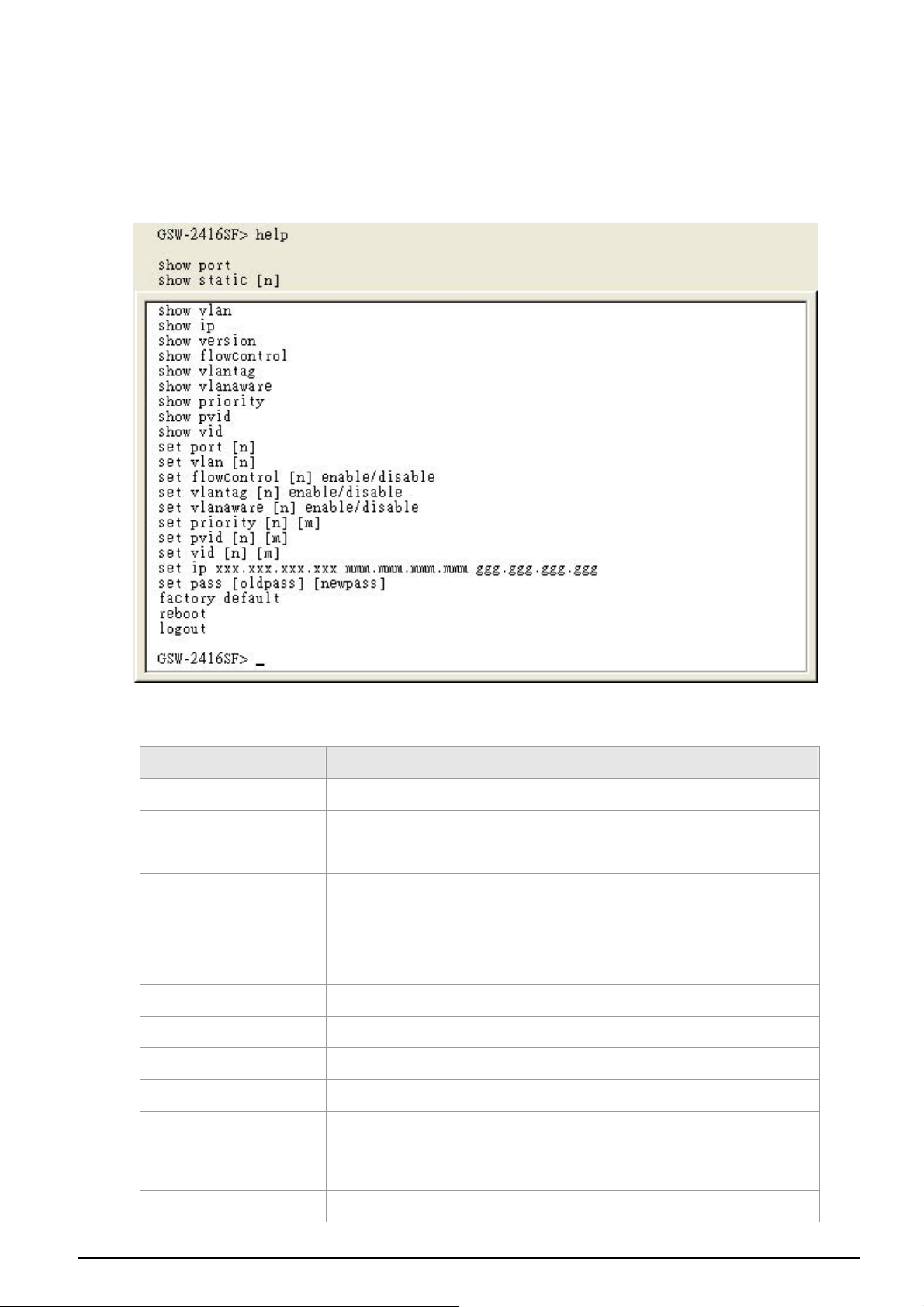
The GSW-2416SF allows users to configure the device via command line under console interface. Please type “help” or
“?” for all available commands in the”GSW-2416SF
and the detail description shown in Table 4-1.
>” prompt. The screen of available commands in Figure 4-4 appears,
Figure 4-4 GSW-2416SF available commands screen
Command Description
show port Show all port current status of GSW-2416SF.
show static [n] Show per port TX/RX static of GSW-2416SF.
show vlan Show current VLAN group status of GSW-2416SF.
show ip
show version Show current Software and Hardware versions of GSW-2416SF.
show flowcontrol Show current flow control status on each port of GSW-2416SF.
show vlantag Show current VLAN Tagged status on each port of GSW-2416SF.
show vlanaware Show current VLAN aware status on each port of GSW-2416SF.
show priority Show current priority status of GSW-2416SF.
show pvid Show current PVID value on each port of GSW-2416SF.
Show current IP subnet address and default gateway information of
GSW-2416SF.
show vid Show current VLAN ID of each VLAN Group of GSW-2416SF.
set port [n]
set vlan [n] Assign port to specific VALN Group of GSW-2416SF.
EM-GSW2416SFv1 - 14 -
Set per port auto-negotiation, speed duplex mode, and admin down of
GSW-2416SF.
Page 15
set flowcontrol [n]
enable/disable
Enable/Disable the flow control function to specific port [n] of GSW-2416SF.
set vlantag [n]
enable/disable
set vlanaware [n]
enable/disable
set priority [n] [m] Allow to configure the priority setting of GSW-2416SF.
set pvid [n] [m] Assign PVID on each port of GSW-2416SF.
set vid [n] [m] Assign VLAN ID [m] to specific VLAN Group [n]
set IP xxx.xxx.xxx.xxx,
mmm. mmm, mmm, mmm,
ggg.ggg.ggg.ggg
set pass [oldpass]
[newpass]
factory default Reset the GSW-2416SF to factory default mode.
reboot Reboot the GSW-2416SF.
logout Logout console interface of GSW-2416SF.
Table 4-1 Detail description of GSW-2416SF available commands
Enable/Disable the VLAN Tagging to specific egress port of GSW-2416SF.
Enable/D
Assign IP address, subnet mask, gateway of GSW-2416SF.
Change the default password of GSW-2416SF, the maximum length is 8
characters.
isable VLAN-Aware function to specific port of GSW-2416SF.
#Notice: Only accept command in lowercase letter under console interface.
4.4.2 Show command
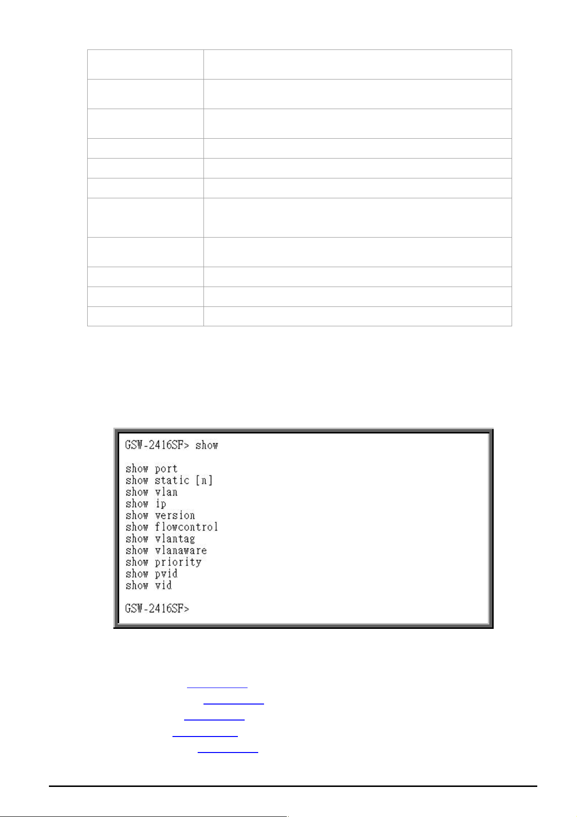
From the main menu screen (see Figure 4-3), input “show” and press enter. The show command list screen in Figure 4-5
appears.
This s ist contains el
how command l even items:
w port : Ple
sho ase refer to chap
sho : Please refer to cw static [n]
show vlan : Please refer to chapter 4.4.2.3
sho refer to chapter
w ip : Please
sho lease refer to chw version : P apter 4.4.2.5.
Figure 4-5 Show command list screen
ter 4.4.2.1.
hapter 4.4.2.2.
.
4.4.2.4.
EM-GSW2416SFv1 - 15 -
Page 16
sho se refer to chapter 4.4.2.6w flowcontrol : Plea .
sho e refer to ch
w vlantag : Pleas
sho ease refer to w vlanaware : Pl
sho e refer to chapter 4.4.2.9w priority : Pleas
sho r to chapt
w pvid : Please refe
show chapter 4.4.2.11 vid : Please refer to
apter 4.4.2.7.
chapter 4.4.2.8.
.
er 4.4.2.10.
.
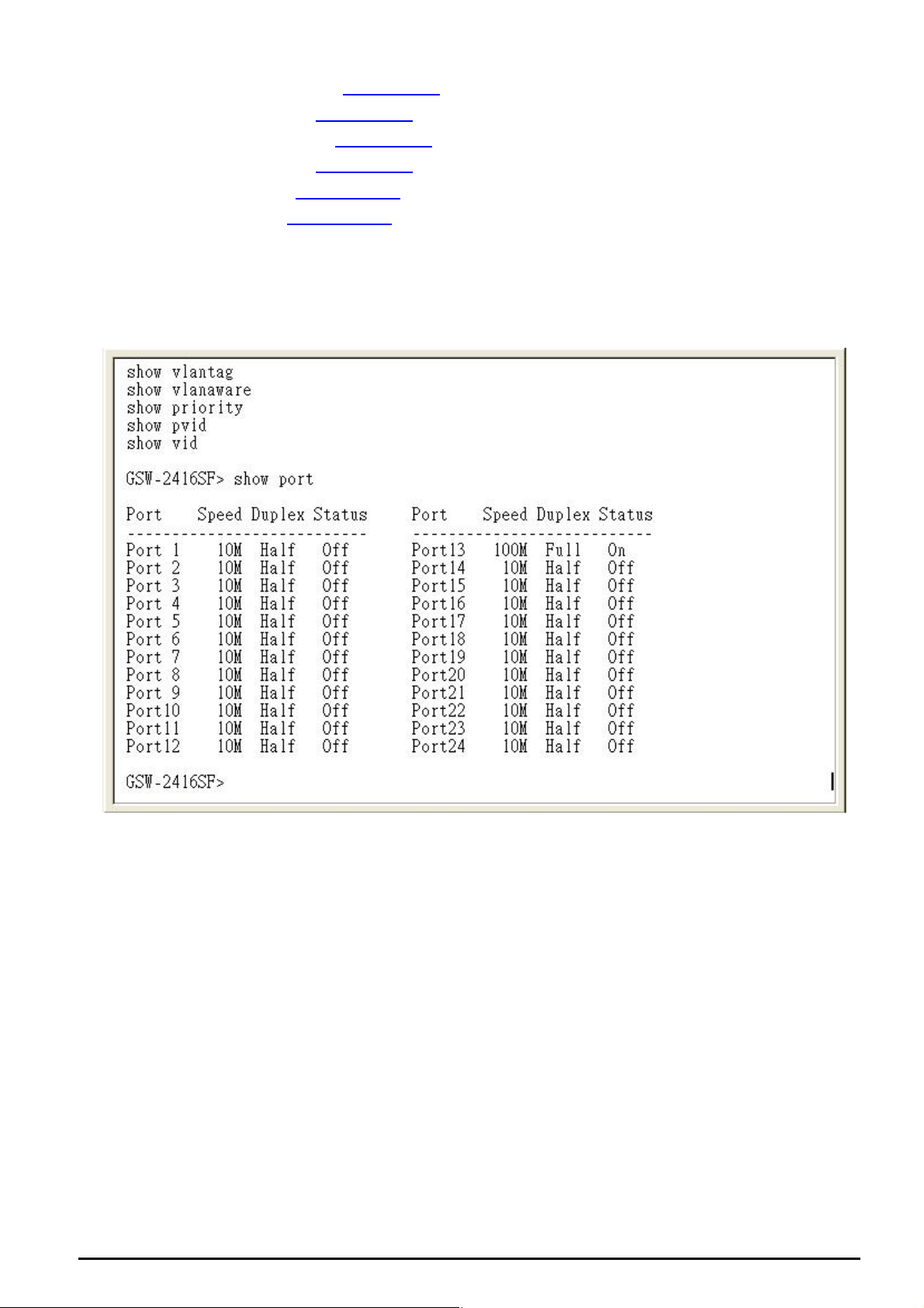
4.4.2.1
Display atus of the Switch and the
correct as below:
Show of GSW-2416SF. The screen in Figure 4-6 appears.
Show port
the status on each port of GSW
usage is shown
port: to view all port status
-2416SF, this command allows you to view the port st
Figure 4-6 All port Status screen
4.2.2.2 Show static [n]
Display the traffic static on specific port of GSW-2416SF, the content include the following items :
z TX OK: Number of transmitted packets.
z RX OK: Number of received packets.
z TX Error: Number of transmitted packets with error ( CRC error etc).
z RX Error: Number of received packets with error (CRC error etc).
Show static [n]: n is the Port ID, n=1-24. T o view one specific port static of GSW-2416SF, the port static screen in Figure
4-7 appears.
EM-GSW2416SFv1 - 16 -
Page 17
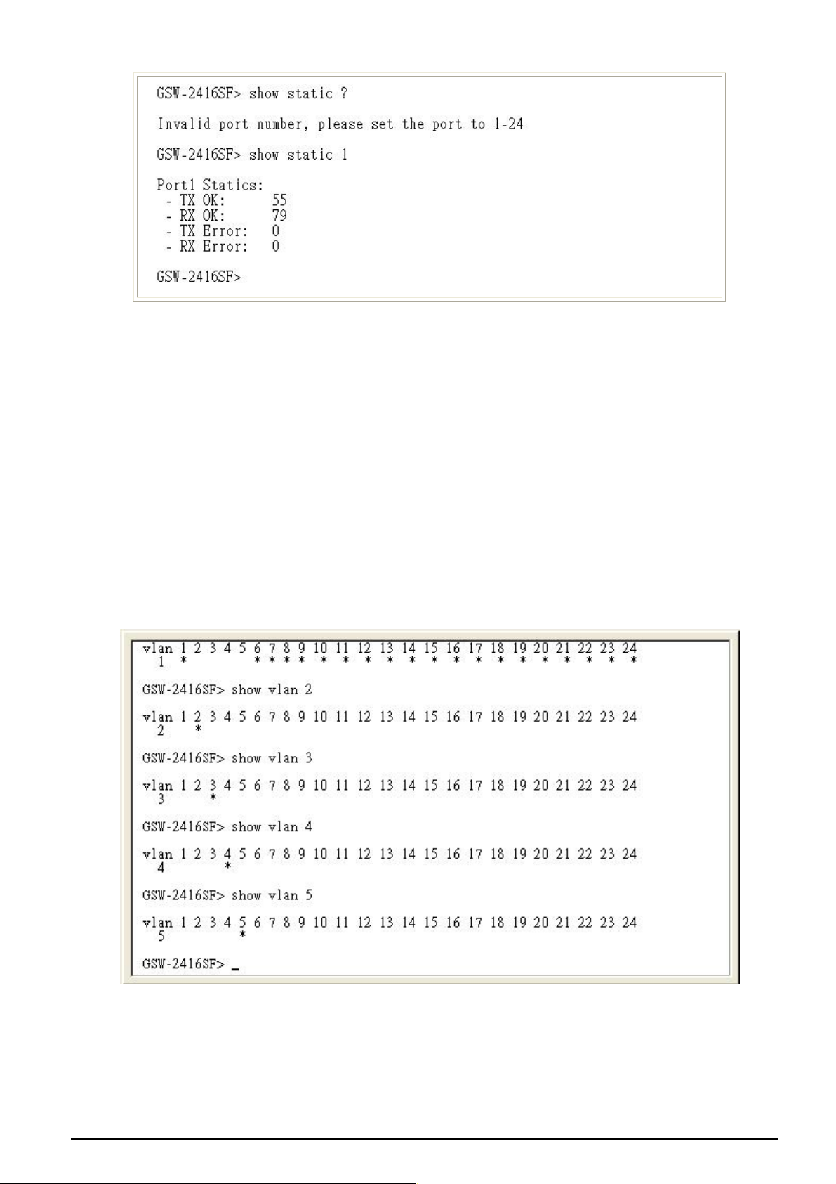
Figure 4-7 Per port static screen
#Notice:
The TX/RX packets counted with error might because:
z Packet with a bad FCS.
z Packets were less than 64 bytes or greater than 1522 bytes.
z Packets were dropped due to lack of resources.
4.4.2.3 Show vlan [n]
Display one specific VLAN group status of GSW-2416SF. GSW-2416SF supports up to 24-port based VLAN Groups and
the correct usage is shown as below:
Show vlan to view all VLAN Group and port member assigned status.
Show vlan [n] n=1-24, to view one specific VLAN Group and port member assigned status.
[n] is the VLAN Group ID.
The specific VLAN Group status screen in Figure 4-8 appears.
Figure 4-8 VLAN group status screen
EM-GSW2416SFv1 - 17 -
Page 18

4.4.2.4 Show ip
Display the current IP address, netmask and gateway of GSW-2416SF. The IP subnet address information screen in
Figure 4-9 appears.
Figure 4-9 IP subnet address information screen
4.4.2.5 Show version
Display the system information of GSW current software version and issued hardware version.
The version information screen in Figure 4-10 appears.
-2416SF, such as
Figure 4-10 System information screen
EM-GSW2416SFv1 - 18 -
Page 19

4.4.2.6 Show flowcontrol
Display the flow control status on all ports of GSW-2416SF, this command allows you to view per port flow control status
the Switch.
Enabled – 802.3x flow control is enabled on Full-Duplex mode or Backpressure is enabled on Half-Duplex mode..
Disabled – No flow control or backpressure function on no matter Full-Duplex or Half-Duplex mode.
The flow control status screen in Figure 4-11 appears.
of
Figure 4-11 All ports flow control status screen
4.4.2.7 Show vlantag
Display the VLAN Tagging behavior on all ports of GSW-2416SF.
Enabled - traffic is transmitted as tagged frames.
Disabled -traffic is transmitted as untagged frames.
The all ports VLAN Tagging status screen in Figure 4-12 appears.
Figure 4-12 All ports VLAN Tagging status screen
EM-GSW2416SFv1 - 19 -
Page 20

4.4.2.8 Show vlanaware
Display current VLAN-aware status on each port of GSW-2416SF.
Enabled – Tagged
Disabled - Tagged
Frame remain original VID while leaving tagged port.
Frame wouldn’t remain original VID while leaving tagged port.
The VLAN-aware status screen in Figure 4-13 appears.
F
igure 4-13 The VLAN-aware status screen
4.4.2.9 Show priority
the current priority status of GSW-2416SF.The allow
Display ed priority values are from 0-7. The priority status display
en in Figure 4-14 appears.
scre
Figure 4-14 Display 802.1p priority status screen.
EM-GSW2416SFv1 - 20 -
Page 21

4.4.2.10 Show pvid
Display the current per port PVID of GSW-2416SF. The Allowed PVID values are form 0-4095. The per port PVID display
screen in Figure 4-15 appears.
Figure 4-15 Display PVID screen
4.4.2.11 Show vid
Display the current VLAN ID of each VLAN Group, the VLAN Groups and ID mapping status display screen in Figure 4-16
appears.
Figure 4-16 VLAN ID of each VLAN Group status screen
EM-GSW2416SFv1 - 21 -
Page 22

4.4.3 Set command
From the main menu screen (see Figure 4-3), input “set” and press enter. The set command list screen in Figure 4-17
appears.
Figure
This set command list contains ten items:
Set port [n]: Please refer to chapter 4.4.3.1
Set vlan [n]: Please refer to chapter 4.4.3.2
Set flowcontrol [n] enable/disable: Please refer to chapter 4.4.3.3
Set vlantag [n] enable/disable: Please refer to chapter 4.4.3.4
Set vlanaware [n] enable/disable: Please refer to chapter 4.4.3.5
Set priority [n] [m]: Please refer to chapter 4.4.3.6
Set pvid [n] [m]: Please refer to chapter 4.4.3.7
Set vid [n] [m]: Please refer to chapter 4.4.3.8
Set ip xxx.xxx.xxx.xxx.mmm.mmm.mmm.mmm.ggg.ggg.ggg.ggg: Please refer to chapter 4.4.3.9
Set pass [oldpass] [newpass]: Please refer to chapter 4.4.3.10
4-17 Set command list screen
.
.
.
EM-GSW2416SFv1 - 22 -
Page 23

4.4.3.1 Set port [n]
This command allows configuring per port parameters of GSW-2416SF. the correct usage is shown as below:
Set port [n]: n=1-24, to configuring per port parameters of GSW-2416SF.
Default setting: (1) Auto Speed
The configuring per port parameters screen in Figure 4-18 appears and the detail description shown in table 4-2.
Figure 4-18 Port Configuration screen
Object Description
(1) Auto Speed
(2) 10 Half
(3) 10 Full
(4) 100 Half
(5) 100 Full
(6) 1000 Full
(7) Disable
Setup Auto negotiation of each port.
Force sets 10Mbps/Half-Duplex mode for specific port.
Force sets 10Mbps/Ful
Force sets 100Mbp
Force sets 100Mb
Force sets 10000Mbps/F
Disable or Shutdown the specific port
Table 4-2 Descriptions of the Port Confi
l-Duplex mode for specific port.
s/Half-Duplex mode for specific port.
ps/Full-Duplex mode for specific port.
ull-Duplex mode for specific port.
guration screen Objects
4.4.3.2 Set v
This command allows configuring up to 24-port based VLAN Groups of GSW-2416SF. The correct usage is shown as
below:
Set vlan [n]: n=1-24, to configuring 24 VLAN Groups of GSW-2416SF. [n] is the VLAN Group ID. And the following
Please input port number (1-24), exit press enters: Add/Remove port to the current VLAN Group, “*” means port had
been assign to the VLAN Group.
Default setting: none
The configuring VLAN Groups screen in Figure 4-19 appears. (Assign port 1, port 6 and port 7 to VLAN Group 1)
lan [n]
message appears:
EM-GSW2416SFv1 - 23 -
Page 24

Figure 4-19 VLAN members Configuration screen
#Notice:
Change VLAN settings for every time, you have to reboot the switch to apply new settings.
4.4.3.3 Set flowcontrol
This command allows configuring per port flow control function of GSW-2416SF. The correct usage is shown as below:
Set flo
Defa
The configuring per port flow con
wcontrol [n] enable/disable
[n]=1-24, n is the specific Port ID.
Enable –
Disable – No flow r backpressure function on no matter Full-Duplex or Half-Duplex mode.
ult setting: Enable
802.3x flow control is enabled on Full-Duplex mode or Backpressure is enabled on Half-Duplex mode.
control o
trol screen in Figure 4-20 appears.
EM-GSW2416SFv1 - 24 -
Figure 4-20 Flow Control port Configuration screen
Page 25

4.4.3.4 Set vlantag
This is an additional function of VLAN configuration.
This command allows configuring per port VLAN Tagged/Untagged status. When adding a VLAN to selected port, it tells
the switch whether to keep or remove the tag from a frame on egress. The correct usage is shown as below:
Set vlantag [n] enable/disable
[n]=1-24, n is the specific Port ID.
Enable – keep the tag from a frame on egress.
Disable – Remove the tag from a frame on egress.
Default Setting: Disable
The configuring per port VLAN Tagging screen in Figure 4-21 appears.
Figure 4-21 Per Port VLAN Tagging Configuration screen
#Notice:
Change VLAN settings for every time, you have to reboot the switch to apply new settings.
4.4.3.5 Set vlanaware
This is an additional function of VLAN configuration.
This command allows disable or enable per port vlan aware function of GSW-2416SF. The correct usage is shown as
below:
Set vlanaware [n] enable/disable
[n]=1-24, n is the specific Port ID.
Enabled – Tagged
Disabled - Tagged
Default Setting: Disable
The vlan-aware mode setting screen in Figure 4-22 appears
Frame remain original VID while leaving tagged port.
Frame wouldn’t remain original VID while leaving tagged port.
EM-GSW2416SFv1 - 25 -
Page 26

Figure 4-22 VLAN aware Configuration screen
#Notice:
Change VLAN settings for every time, you have to reboot the switch to apply new settings.
4.4.3.6 Set priority
This command configures the default 802.1p port priority assigned for untagged packets for a specific port of
GSW-2416SF. The correct usage is shown as below:
Set priority [n] [m]
[n]=1-24, n is the specific Port ID of GSW-2416SF.
[m] = 0-7, m is 802.1p priority.
Default Setting: 0
The per port priority setting screen
in Figure 4-23 appears. (Set Port 1 with priority “7”)
Figure 4-23 Priority Configuration screen
EM-GSW2416SFv1 - 26 -
Page 27

4.4.3.7 Set pvid
This is an additional function of VLAN configuration.
This command allows assign PVID for selected port of GSW-2416SF. The correct usage is shown as below:
Set pvid [n] [m]
[n]=1-24, n is the specific Port ID of GSW-2416SF.
[m] = 1-4095, 0 reserved for management purpose; m is allowed VLAN ID.
Default Setting: 0
To remote control the GSW-2416SF, the connect port have to set with PVID=0
The PVID setting screen in Figure 4-24 appears. (Example: Set Port 1 with PVID=3)
Figure 4-24 PVID Configuration screen
#Notice:
Change VLAN settings for every time, you have to reboot the switch to apply new settings.
4.4.3.8 Set vid
This command allows assign VLAN ID for specific VLAN Group of GSW-2416SF. The correct usage is shown as below:
Set vid [n] [m]
[n]=1-24, n is the specific VLAN Group of GSW-2416SF.
[m] = 0-4095, m is allowed VLAN ID.
Default Setting: 0
The VID setting screen in Figure 4-25 appears. (Example: Set VALN Group 2 with VLAN ID=3)
EM-GSW2416SFv1 - 27 -
Page 28

Figure 4-25 VID Configuration screen
#Notice:
Change VLAN settings for every time, you have to reboot the switch to apply new settings.
4.4.3.9 Set ip xxx.xxx.xxx.xxx.mmm.mmm.mmm.mmm.ggg.ggg.ggg.ggg
This command allows assign IP address, netmask and gateway of GSW-2416SF. The correct usage is shown as below:
set ip 192.168.0.1 255.255.255.0 192.168.0.254 and press <Enter>
After the setting be completed, you can use the new IP address to access the WEB UI of GSW-2416SF.
Default Setting:
IP: 192
.168.0.100
Netmask: 255.255.255.0
Default Gateway: 192.168.0.254
The IP subnet add
ress setting screen in Figure 4-26 appears.
EM-GSW2416SFv1 - 28 -
Page 29

Figure reen
4.4.3.10 Set p
This command allows assign password of GSW-2416SF. The correct usage is shown as belo
set pass [oldpass] [newpass]
Default Setting: no password
ass
4-26 IP subnet address configuration sc
w:
#Notice: The symbol “[“ and “]” are required for both old password and new password. And once the
setting be completed, the next time login have to u
The password setting screen in Figure 4-27 appears. (Example: Setting new password =” test “)
se the new password.
Figure 4-27 Password configuration screen
#Notice:
1. For security reason, please change and memorize the new password after this first setup.
2. The maximum length is 8 characters.
EM-GSW2416SFv1 - 29 -
Page 30

4.4.4 Factory default
This command allows rest GSW-2416SF to factory default mode. The factory default screen in Figure 4-28 & 4-29 appears.
Figure 4-28 Factory default screen
Figure 4-29 Factory default screen
EM-GSW2416SFv1 - 30 -
Page 31

4.4.5 Reboot
This command allows reboot GSW-2416SF, the reboot screen in Figure 4-30 & 4-31 appears.
Figure 4-30 Switch reboot screen
Figure 4-31 Switch reboot screen
EM-GSW2416SFv1 - 31 -
Page 32

4.4.6 Logout
This command provides logout the GSW-2416SF, the screen in Figure 4-32 appears.
Fig en
ure 4-32 GSW-2416SF Logout scre
EM-GSW2416SFv1 - 32 -
Page 33

4.5 Firmware Update
This section will show you how to use X-modem to update the firmware of GSW-2416SF.
Firmware update requirements
GSW-2416SF switch
Latest firmware version
VT100 terminal, or a personal computer or workstation with terminal emulation software
RS-232/DB9 null modem cable
Update procedure:
1. After login the GSW-2416SF, enter “update” in the”GSW-2416SF>” prompt. Then the message will ask you to use
the Xmodem to send the firmware file. The firmware update screen in Figure 4-33 appears:
Figure 4-33 Firmware Update
Select and send the firmware file by your terminal emulation software. As the screens show in Figure 4-34 and Figure
2.
4-35:
#Notice:
1. Make sure that you had selected the correct firmware file that just for the GSW-2416SF and read the release note
before you run the update procedure.
2. Don’t power off the switch while updating firmware or unexpected result occurred.
EM-GSW2416SFv1 - 33 -
Page 34

Figure 4-34 Firmware Update
Figure 4-35 Xmodem transmit
After the file send be completed, the system will reboot automatically to the login screen. You can check if the
Software version been updated. The screen in
Figure 4-36 System reboot screen
Figure 4-36 appears:
EM-GSW2416SFv1 - 34 -
Page 35

5. WEB MANAGEMENT
Before login the Web interface of GSW-2416SF, please setup the “IP Address” with local serial console port (RS232 port)
and use this IP address to configure GSW-2416SF through the Web interface.
Or modify your PC’s IP domain to the same with GSW-2416SF then use the default IP address (192.168.0.100) to remote
configure GSW-2416SF through the Web interface.
5.1 Login in to the Switch
To access the Web-browser interface you must first enter the user name, the default user name is "admin" without
password. You will see the following screen comes out on the Web browser program:
Figure 5-1 The GSW-2416SF login Web Page screen
After the User name and Password is entered, you will see the web main menu screen.
Figure 5-2 The web main menu screen of GSW-2416SF
EM-GSW2416SFv1 - 35 -
Page 36

5.2 Port Config
This section provides current ports status and detail setting of each port of GSW-2416SF. The screen in Figure 5-3
appears and Table 5-1 describes the port configuration object of switch.
Figure 5-3 GSW-2416SF Port Configuration Web Page screen
#Notice:
Due to VID value “0” is reserved for management purpose, the management linked port have to configured with PVID=0.
For example: The management PC connected to Port-24 of the switch via Ethernet. Port-24 has to be configured with
PVID=0, and the management has to be configured within the same domain as the switch.
EM-GSW2416SFv1 - 36 -
Page 37

Object Description
Port
Mode
Flow Control
VLAN aware
* Additional function
VLAN tag
* Additional function
Indicate port 1 to port 24.
Allow configuring the port speed and operation mode. Draw the menu bar to select the mode.
z Auto Speed - Setup Auto negotiation.
z 10 half - Force sets 10Mbps/Half-Duplex mode.
z 10 Full - Force sets 10Mbps/Full-Duplex mode.
z 100 half - Force sets 100Mbps/Half-Duplex mode.
z 100 full - Force sets 100Mbps/Full-Duplex mode.
z 1000 full - Force sets 10000Mbps/Full-Duplex mode.
z Disable - Shutdown the port manually.
Allow Enable or Disable flow control for selected port.
Enable – 802.3x flow control is enabled on Full-Duplex mode or Backpressure is enabled on
Half-Duplex mode.
Disable – No flow control or backpressure function on no matter Full-Duplex or Half-Duplex mode
Allow Enable or Disable VLAN aware for selected port.
Enable – Tagged
Disable - Tagged
Allow Enable or Disable VLAN Tag for selected port.
When adding a VLAN to selected port, it tells the switch whether to keep or remove the tag from a
frame on egress.
Enable - Outgoing frames with VLAN-Tagged.
Disable - Outgoing frames without VLAN-Tagged.
Frame remain original VID while leaving tagged port.
Frame wouldn’t remain original VID while leaving tagged port.
VLAN priority
PVID
* Additional function
Allow assign 802.1p priority for selected port.
The range for the priority is 0-7 (0~3 for low priority; 4~7 for high priority )
Allow assign PVID for selected port.
The range for the PVID is 1-4095 ;
ID will be inserted into all untagged frames entering the ingress po
The PV rt.
as the VLAN ID that the port belong to VLAN group, or the untagged traffic will be dropped.
0 reserved for management purpose
The PVID must as same
Table 5-1 Descriptions of the Port Configuration screen Objects
Click “Apply” button to affect the configured function.
#Notice:
Change VLAN settings for every time, you have to reboot the switch to apply new settings.
N Tag:
VLA
Tagged-based VLAN is an IEEE 802.1Q specification standard. Therefore, it is possible to create a VLAN across devices
from different switch venders. IEEE 802.1Q VLAN uses a technique to insert a "tag" into the Ethernet frames. Tag contains
a VLAN Identifier (VID) that indicates the VLAN numbers.
To set the outgoing frames are VLAN-Tagged frames or untagged.
Tag: outgoing frames with VLAN-Tagged.
UnTag: outgoing frames without VLAN-Tagged.
PVID:
Set the PVID that will be assigned to untagged traffic on a given port. This feature is useful for accommodating devices that
you want to participate in the VLAN but that don't support tagging. The switch each port allows user to set one PVID, the
range is 0~4095, default VLAN ID is 0. The PVID must as same as the VLAN ID that the port belong to VLAN group( See
chapter 5.3 – VLAN Setup), or the untagged traffic will be dropped.
EM-GSW2416SFv1 - 37 -
Page 38

5. Setup
3 VLAN
A V LAN (VLAN) ng that limits the broadcast domain. It allows you to isolate network traffic
irtual is a logical network groupi
so only VLAN members. Basically, creating a VLAN from a switch is
members of the VLAN receive traffic from the same
logically uivalent of ices
are still plug into the same tch
The GSW-2416SF switch s po In the default configuration, VLAN
support is “disable”.
eq
reconnecting a group of network devices to another Layer 2 switch. How ever, all the network dev
swi physically.
up rts Port-Base VLAN setting in web management page.
5.3.1 VLAN Group an m
Thi es of GSW-2416SF, the screen in Figure 5-4
s section provid current status and member setting of each VLAN group
appears.
d ember settings
Figure 5-4 GSW-2416SF VLAN Settings Web Page screen
1. Enter VLAN ID for the selected VLAN group. There are maximum 24 VLAN groups to provide configured and the
range for the VLAN ID is 1-4095; 0 res
2. Checked the Member box to select the memb
3. Afte
r setup completed, please press “Apply” to take affect.
erved for management purpose.
ers for the VLAN group.
4. To setup another VLAN Group, click the VLAN Group ID button. After the web page load completed, repeat the
previous steps.
5. To remove a port from specific VLAN group, just cancel the Member check Box and press “Apply” to take affect.
#Notice:
Change VLAN settings for every time, you have to reboot the switch to apply new settings.
EM-GSW2416SFv1 - 38 -
Page 39

5.3.2 VLAN setting example:
5.3.2.1 Two separate VLAN
The diagram shows how the switch handle Tagged and Untagged traffic flow for two VLANs. VLAN Group 2 and VLAN
Group 3 are separated VLAN. Each VLAN isolate network traffic so only members of the VLAN receive traffic from the
same VLAN members. The screen in Figure 5
-5 appears and Table 5-2 describes the port configuration of switch.
Figure 5-5 two separate VLAN diagram
VLAN Group VID Untagged Members Tagged Members
VLAN Group 1 1 Port-1,Port-2 Port-3
VLAN Group 2 2 Port-4,Port-5 Port-6
VLAN Group 3 3 Port-7~Port-24 N/A
Table 5-2 VLAN and Port Configuration
The scenario described as follow:
Untagged packet entering VALN 2
1. While [PC-1] transmit an untagged packet enters Port-1, the switch will tag it w ith a VLAN Ta g=2. [PC-2] and
[PC-3] will received the packet through Port-2 and Port-3.
2. [PC-4],[PC-5] and [PC-6] received no packet.
3. While the packet leaves Port-2, it will be stripped away it tag becoming an untagged packet.
4. While the packet leaves Port-3, it will keep as a tagged packet with VLAN Tag=2.
Tagged packet entering V
5. While [PC-3] transmit a tagged packet with VLAN Tag=2 enters Port-3, [PC-1] and [PC-2] will received the
packet through Port-1 and Port-2.
6. While the packet leaves and Port-2, it will be stripped away it tag becoming an untagged packet.
Untagged packet entering VLAN 3
1. While [PC-4] transmit an untagged packet enters Port-4
[PC-6] will received the packet through Port-5 and Port-6.
LAN 2
Port-1
, the switch will tag it with a VLAN Tag=3. [PC-5] and
2. While the packet leaves Port-5, it will be stripped away it tag becoming an untagged packet.
3. Wh
ile the packet leaves Port-6, it will keep as a tagged packet with VLAN Tag=3.
#Notice:
At this example, VLAN Group 1 just set as default VLAN, but only focus on VLAN 2 and VLAN 3 traffic flow.
EM-GSW2416SFv1 - 39 -
Page 40

Setup steps
1. VLAN Group
Set VALN Group 1 = default-VLAN
Add two VLANs – VLAN 2 and VLAN 3
VLAN Group 2 with VID=2
VLAN Group 3 with VID=3
2. Assign VLAN Member :
VLAN 2: Port-1, Port-2 and Port-3
VLAN 3: Port-4, Port-5 and Port-6
VLAN 1: All other ports – Port-7~Port-24
3. Assign PVID for each port:
Port-1, Port-2 and Port-3: PVID=2
Port-4, Port-5 and Port-6: PVID=3
Port-7~Port-24: PVID=1
4. Enable VLAN Tag for specific ports
VLAN Tag Enabled: Port-3 (V
with VID (VLAN ID)=1
LAN-2) and Port-6 (VLAN-3)
T
he Port VLAN configuration would be as the following screen in Figure 5-6.
Figure 5-6 Port Configuration Web page screen
EM-GSW2416SFv1 - 40 -
Page 41

Figure 5-7 VLAN 1 member assign Web page screen
Figure 5-8 VLAN 2 member assign Web page screen
EM-GSW2416SFv1 - 41 -
Page 42

Figure 5-9 VLAN 2 member assign Web page screen
#Notice:
Change VLAN settings for every time, you have to reboot the switch to apply new settings.
5.3.2.2 Overlap VLAN
The scenario described as follow:
1. Port-16 is the file server port for all the workstations
2. Port-1 to Port-15 is different devices that do need to see each other
Setup steps
1. Port Setting
1.1 Assign VLAN 1 as the default VLAN group for all ports
1.2 Assign VLAN 2 for the second VLAN group with Port-1 and Port-16
1.3 Repeat the same steps for Port-2 to Port-15. i.e. 2 & 16, 3 & 16, ….., 15 & 16
2. PVID setup
2.1 Assign “1” (i.e. ID of VLAN 1) to Port-16 as its PVID (Port VLAN ID).
2.2 Assign “2” to Port-1 as its PVID
2.3 Repeat above steps for Port-2 to Port-15 with its PVID, i.e. 3 (Port-2), 4 (Port-3), to 16 (Port-15)
After the above steps Port-1 to Port-15 is being separated physically due to it belongs to different VLAN
groups (different VLAN). However , they all can access Port-16 due to Port-16 is using PVID 1 to communicate
with port 1 to port 15.
#Notice:
Change VLAN settings for every time, you have to reboot the switch to apply new settings.
EM-GSW2416SFv1 - 42 -
Page 43

5.4 Port Trunk Setup
This section allows you to disable or enable trunk function of two ports or four ports together to speed up data transmission.
The GSW-2416SF provides up to 3 Trunk group, each group supports maximum 4 ports, the screen in Figure 5-10
appears.
Figure 5-10 GSW-2416SF Port Trunk Setup Web Page screen
To configure the Port Trunk, with the specific Trunk ID, select Member ports to meet required. The screen in Figure 5-11
appears:
Figure 5-11 GSW-2416SF Port Trunk Setup Web Page screen
and members are fixed assign. Please refer to the following table: The Trunk group
ID Member
z Disable
01
z 01,02
z 01,02,03,04
z Disable
02
03
z 09,10
z 09,10,11,12
z Disable
z 17,18
z 17,18,19,20
EM-GSW2416SFv1 - 43 -
Page 44

#Notice:
1. After turn on the port trunk feature, port 1 and port 2 or port 17,18,19,20 should connect to another switch,
such as another GSW-2416SF, that also supports port trunk feature to double the bandwidth in between.
Otherwise, if the connected switch do not support port trunk, it will cause network loop and hangs the w
network.
2. The GSW-2416SF doesn’t support LACP (Link Aggregation control Protocol) trunk type yet. Connect with
LACP type switch the trunk function might be failed.
3.
Within the same Trunk Group, the member ports have to be configured with the same settings, such as port speed and
VLAN etc.
hole
EM-GSW2416SFv1 - 44 -
Page 45

5.5 Status
5.5.1 Port Status
Th
is section displayed the current link status of each port on GSW-2416SF. It’s help the manager easy to get the
connection info. The screen in Figure 5-12 appears.
Figure 5-12 GSW-2416SF Port Status Web Page screen
5.5.2 Statistics
This section displayed the current traffic statistics of each port on GSW-2416SF. The screen in Figure 5-13 appears.
The content of the statistics table include the following items:
z TX OK: Number of transmitted packets.
z RX OK: Number of received packets.
z TX Error: Number of transmitted packets with error ( CRC error etc).
z RX Error: Number of received packets with error (CRC error etc).
(The unit of the above value is “packets”)
#Notice:
The TX/RX packets counted with error might because:
z Packet with a bad FCS.
z Packets were less than 64 bytes or greater than 1522 bytes.
z Packets were dropped due to lack of resources.
EM-GSW2416SFv1 - 45 -
Page 46

Figure 5-13 GSW-2416SF Port Statistics Web Page screen
There’re also two buttons at the statistics web page – “Clear” and “Refresh”.
Press the “Clear” button will clear the current traffic statistic value.
Press the “Refresh” button will update the latest traffic statistic value, especially for the traffic keeps on transmitting.
EM-GSW2416SFv1 - 46 -
Page 47

5.6 Misc Configuration
This section provides Misc Configuration of GSW-2416SF.
5.6.1 System Setup
This section provides System Configuration of GSW-2416SF, the screen in Figure 5-14 appears and table 5-4 descriptions
the System Configuration objects of GSW-2416SF.
Figure 5-14 GSW-2416SF System Configuration Web Page screen
Object Description
Mac address
S/W Version
H/W Version
IP Address
Subnet Mask
Gateway
Name
Password
Display Mac address of GSW-2416SF.
Display firmware version of GSW-2416SF.
Display Hardware version of GSW-2416SF
Allow user to assign new IP address of GSW-2416SF, after setup completed.
Please press “Apply” button and switch will take effect immediately.
Allow user to assign new Subnet Mask of GSW-2416SF, after setup completed.
Please press “Apply” button and switch will take effect immediately.
Allow user to assign new Gateway of GSW-2416SF, after setup completed. Please press
“Apply” button and switch will take effect immediately.
Display the administrator account of the switch. Default account is “admin”
Allow user to change the password and maximum up to 8 characters
Please press “Apply” button and switch will take effect immediately.
Table 5-4 Descriptions of the System Configuration screen Objects
Once the setup completed and the IP address of the device be changed, you might loss the web connection. Modify your
PC’s IP domain to the same with the new IP address of GSW-2416SF.
EM-GSW2416SFv1 - 47 -
Page 48

5.7 Tools
This section provides two management tools of GSW-2416SF- Reboot and Factory Reset.
5.7.1 Reboot
This section provides reboot GSW-2416SF, after choose this function and the following screen appears in Figure 5-15.
Please press “Warm Reboot” button to take effect i
browser and re-login web interface with correct username “admin” and password, the screen in Figure 5-16 appears.
mmediately. After system reboot, the manager has to refresh the
Figure 5-15 The GSW-2416SF reboot system Web Page screen
Figure 5-16 The GSW-2416SF login Web Page screen
EM-GSW2416SFv1 - 48 -
Page 49

5.7.2 Factory Reset
This section provides reset GSW-2416SF to factory default mode, default value to as followin
z Default IP address: 192.168.0.100
z Subne
z Default Gateway: 192.168.0.254
z The other setting value is back to disable or none.
After choose this function and the following screen appears in Figure 5-17.
t mask: 255.255.255.0
g configuration:
Figure 5-17 The GSW-2416SF reset to factory default Web Page screen
Please press “Factory Reset” system reboot, the
m
anager has to refresh the browser and re-login web interface with default username “admin” without password, the
screen in Figure 5-18 appears.
button to take effect and the switch will reboot automatically. After
Figure 5-18 The GSW-2416SF login Web Page screen
EM-GSW2416SFv1 - 49 -
Page 50

5.8 Logout
This section allows to logout the GSW-2416SF. Press “Logout” item in the Web Menu, it take effect immediately. If the
manager wa ” button. The screen in Figure 5-19 and Figure 5-20 appears.
nts to re-login, press the “Re-Login
Figure 5-19 The GSW-2416SF Logout Web Page screen
Figure 5-20 The GSW-2416SF login Web Page screen
EM-GSW2416SFv1 - 50 -
Page 51

6. SWITCH OPERATION
6.1 Address Table
The Switch is implemented with an address table. This address table composed of many entries. Each entry is used to
store the address information of some node in network, including MAC address, port no, etc. This information comes
from the learning process of Ethernet Switch.
6.2 Learning
When one packet comes in from any port. The Switch will record the source address, port no. And the other related
information in address table. This information will be used to decide either forwarding or filtering for future packets.
6.3 Forwarding & Filtering
When one packet comes from some port of the Ethernet Switching, it will also check the destination address besides
the source address learning. The Ethernet Switching will lookup the address-table for the destination address. If not
found, this packet will be forwarded to all the other ports except the port which this packet comes in. And these ports
will transmit this packet to the network it connected. If found, and the destination address is located at different port
from this packet comes in, the Ethernet Switching will forward this packet to the port where this destination address is
located according to the information from address table. But, if the destination address is located at the same port with
this packet comes in, then this packet will be filtered. Thereby increasing the network throughput and availability.
6.4 Store-and-Forward
Store-and-Forward is one type of packet-forwarding techniques. A Store-and Forward Ethernet Switching stores the
incoming frame in an internal buffer, do the complete error checking before transmission. Therefore, no error packets
occurrence, it is the best choice when a network needs efficiency and stability.
The Ethernet Switch scans the destination address from the packet-header, searches the routing table provided for
the incoming port and forwards the packet, only if required. The fast forwarding makes the switch attractive for
connecting servers directly to the network, thereby increasing throughput and availability. How ever, the sw itch is most
commonly used to segment existing hubs, which nearly always improves overall performance. An Ethernet Switching
can be easily configured in any Ethernet network environment to significantly boost bandwidth using conventional
cabling and adapters.
Due to the learning function of the Ethernet switching, the source address and corresponding port number of each
incoming and outgoing packet are stored in a routing table. This information is subsequently used to filter packets
whose destination address is on the same segment as the source address. This confines network traffic to its
respective domain, reducing the overall load on the network.
The Switch performs "Store and forward" therefore, no error packets occur. More reliably, it reduces the
re-transmission rate. No packet loss will occur.
6.5 Auto-Negotiation
The STP ports on the GSW-2416SF Switch have built-in “Auto-negotiation”. This technology automatically sets the
best possible bandwidth when a connection is established with another netw ork device (usually at Power On or Reset).
This is done by detect the modes and speeds at the second of both device is connected and capable of, Both
10Base-T and 100Base-TX devices can connect with the port in either Half- or Full-Duplex mode. 1000Base-T can be
only connected in Full-dupl
ex mode.
EM-GSW2416SFv1 - 51 -
Page 52

7.TROUBLESHOOTING
This chapter contains information to help you solve problems. If the Switch is not functioning properly, make sure the
Ethernet Switch was set up
The Link LED is not lit
Solution:
Check the cable connection and remove duplex mode of the Switch.
Some stations cannot talk to other stations located on the other port
Solution:
Please check t
Perf
ormance is bad
So
lution:
Check the full duplex status of the Ethernet Switch. If the Ethernet Switch is set to full duplex and the partner is set to
half duplex, then the performance
100Base-TX port link LED is lit, but the traffic is irregular
Solution:
Check that the attached device is not set to dedicate full duplex. Some devices use a physical or software switch to
change duplex modes. Auto-negotiation may not recognize this type of full-duplex setting.
Why
the Switch doesn’t connect to the network
So
lution:
Check the LNK/ACT LED on the switch Try another port on the Switch Make sure the cable is installed properly Ma
sure the cable is the right type T
How to deal forgotten password situation of GSW-2416SF?
Solution:
1. Please contact Planet switch support team and the mail address is support_switch@planet.com.tw
according to instructions in this manual.
he VLAN, port trunking function that may introduce this kind of problem.
will be poor.
ke
urn off the power. After a while, turn on power again.
EM-GSW2416SFv1 - 52 -
Page 53

APPENDIX A NETWORKING CONNECTION
A.1 Switch‘s RJ-45 Pin Assignments
10/100Base-TX
Contact MDI MDI-X
1 1 (TX +) 3
2 2 (TX -) 6
3 3 (RX +) 1
6 6 (RX -) 2
4, 5, 7, 8 Not used Not used
A.2 1000Mbps, 1000Base-T
Contact MDI MDI-X
1 BI_DA+ BI_DB+
2 BI_DA- BI_DB3 BI_DB+ BI_DA+
4 BI_DC+ BI_DD+
5 BI_DC- BI_DD6 BI_DB- BI_DA7 BI_DD+ BI_DC+
8 BI_DD- BI_DC-
Implicit implementation of the crossover function within a twisted-pair cable, or at a wiring panel, while not expressly
forbidden, is beyond the scope of this standard.
A.3 RJ-45 cable pin assignment
2 1
3 6
There are 8 wires on a standard UTP/STP cable and each wire is color-coded. The following shows the pin allocation
and color of straight cable and crossover cable connection:
2 1 3 6
6
3
2
1
EM-GSW2416SFv1 - 53 -
Page 54

Figure A-1: Straigh and Crossover Cable
t-Through
Please make sure your connected cable
cables into your network.
080
2 -A82050-000
s are with same pin assignment and color as above picture before deploying the
EM-GSW2416SFv1 - 54 -
 Loading...