


Trademarks
Copyright PLANET Technology Corp. 2005.
Contents subject to which revision without prior notice.
PLANET is a registered trademark of PLANET Technology Corp. All other trade-
marks belong to their respective owners.
Disclaimer
PLANET Technology does not warrant that the hardware will work properly in
all environments and applications, and makes no warranty and representation, either implied or expressed, with respect to the quality, performance,
merchantability, or tness for a particular purpose.
PLANET has made every effort to ensure that this User’s Manual is accurate;
PLANET disclaims liability for any inaccuracies or omissions that may have
occurred.
Information in this User’s Manual is subject to change without notice and does
not represent a commitment on the part of PLANET. PLANET assumes no responsibility for any inaccuracies that may be contained in this User’s Manual.
PLANET makes no commitment to update or keep current the information
in this User’s Manual, and reserves the right to make improvements to this
User’s Manual and/or to the products described in this User’s Manual, at any
time without notice.
If you nd information in this manual that is incorrect, misleading, or incomplete, we would appreciate your comments and suggestions.
FCC Warning
This equipment has been tested and found to comply with the limits for a
Class A digital device, pursuant to Part 15 of the FCC Rules. These limits are
designed to provide reasonable protection against harmful interference when
the equipment is operated in a commercial environment. This equipment generates, uses, and can radiate radio frequency energy and, if not installed and
used in accordance with the Instruction manual, may cause harmful interference to radio communications. Operation of this equipment in a residential
area is likely to cause harmful interference in which case the user will be
required to correct the interference at whose own expense.
CE Mark Warning
This is a Class A product. In a domestic environment, this product may cause
radio interference, in which case the user may be required to take adequate
measures.

WEEE Warning
To avoid the potential effects on the environment and human health
as a result of the presence of hazardous substances in electrical and
electronic equipment, end users of electrical and electronic equipment
should understand the meaning of the crossed-out wheeled bin symbol.
Do not dispose of WEEE as unsorted municipal waste and have to collect such WEEE separately.
Revision
PLANET Gigabit Ethernet Switch User’s Manual
FOR MODEL: GSD-800S
Rev: 2.0
Part No. 2010-A35040-000

Table of Contents
Chapter 1 Introduction 1
1.1 Package Contents 1
1.2 How to Use This Manual 1
1.3 Product Features 2
1.4 Product Specifications 3
Chapter 2 Installation 5
2.1 Product Description 5
2.2 Installing a 800S 6
Chapter 3 Configuration 8
3.1 Preparing for configuration 8
3.2 General 9
3.3 Commands 12
3.4 Examples 23
Chapter 4 Web Interface 25
4.1 Starting the Web Interface 25
Chapter 5 Troubleshooting 26
5.2 Address Table 26
5.2 Learning 26
5.3 Forwarding & Filtering 26
5.4 Store-and-Forward 26
5.5 Auto-Negotiation 27
Chapter 6 Trouble Shooting 28
APPENDIX A 29
A.1 Switch‘s RJ-45 Pin Assignments 29
A.2 10/100Mbps, 10/100Base-TX 29


Chapter 1
INTRODUCTION
1.1 Package Contents
Open the box of the Switch and unpack it carefully. The box should contain the following
items:
● The Switch
● Power Cord x 1
● RS-232 Cable x 1
● User s Manual x 1
If any item is found missing or damaged, please contact your local reseller for replacement.
Please retain the carton including the original packing material, and use them against to
repack the product in case there is a need to return it to us for repair.
1.2 How to Use This Manual
This Gigabit Ethernet Switch User Manual is structured as follows:
Chapter 2 Installation
This chapter explains the functions and how to physically install the GSD-800S.
Chapter 3 Conguration
This chapter contains information about the smart function of GSD-800S.
Chapter 4 Web Interface
This chapter contains troubleshooting and specications of GSD-800S
Chapter 5 Switch Operation
This chapter explains the switch operation of GSD-800S.
Chapter 6 Trouble Shooting
This chapter contains troubleshooting of GSD-800S
Appendices
This chapter contains cable information of GSD-800S.
1

3
1.3 Product Features
● Complies with IEEE802.3, 10Base-T, IEEE802.3u, 100Base-TX and
IEEE802.3ab, 1000Base-T
● IEEE802.3x, full-duplex flow control compliant; back-pressure, half-duplex
flow control
● 10/100/1000Mbps 8-port Ethernet / Smart Switch (RJ-45)
● 144 bytes packet buffer and 8K MAC address table, auto-ageing.
● Per port Auto-MDI, MDI-X detection
● Store and Forward switching architecture
● Non-blocking switch fabric
● Automatic source address learning and aging
● RS-232 console interface for console program management of smart feature
● Port trunking support to optionally increase bandwidth between switches
● VLAN support with up to 8 VLAN groups
● 4 Classes of Service selectable on a per port basis and/or checked by IP ToS
header
● Support Port mirroring for port traffic diagnosis with sniffer programs
● 10”, 1U height rack mounting size
● 100~240VAC, 50~60Hz universal power input
2

1.4 Product Specications
Model GSD-800S
Hardware Specification
Network ports 8 10/100/1000Base-T RJ-45 MDI/MDI-X ports
Console port 1 RS-232 DB-9 male
Dimensions 217 x 135 x 43.5 mm (1U height)
Weight 1.1 kg
Power Requirement 100~240 (±10%) VAC, 50-60 (±3) Hz
Power Consumption 21 Watts maximum / 71 BTU/hr maximum
Switch Specification
Switch architecture Store-and-forward
Address Table 8K entries, auto learning/ageing
Flow Control Back pressure for half duplex, IEEE 802.3x for full
duplex
Packet Control Runt & CRC filtering, Broadcast storm control
Switching Fabric 16Gbps
Switch Management
Port Config Configure each port’s speed, duplex mode, flow
control and priority
Port Status Show each port’s link status and speed, duplex
mode
VLAN Up to 8 VLAN groups
Port Trunking 2 port trunk support
Port Mirroring Mirroring port’s in/out traffic
Traffic Prioritization 4 Classes of Service selectable on a per port basis
and / or checked by IP ToS header
Standards Conformance
Network Standards IEEE 802.3 (Ethernet)
IEEE 802.3u (Fast Ethernet)
IEEE 802.3ab
IEEE8023x (flow control)
Operating Temperature 0~50˚C
Storage Temperature -40~70˚C
3

5
Humidity 10% to 90% (Non-condensing)
Regulation Compliance FCC, CE
4
Chapter 2
INSTALLATION
TThis section describes the functionalities of GSD-800S’s components and guides how to
install it on the desktop or shelf. Basic knowledge of networking is assumed. Please read
this chapter completely before continuing.
2.1 Product Description
The PLANET GSD-800S provides 8 Gigabit Ethernet Switch ports. The PLANET GSD-800S
delivers eight ports worth of high-performance, feature-rich integrated Gigabit Ethernet
switching over traditional copper cabling. The GSD-800S is capable of smart functions,
such as VLAN, Port trunking and Prot mirroring. GSD-800S can be congured by out-ofband channel via the console port (RS232) directly. Each port supports 10Mbps, 100Mbps,
and 1000Mbps as well as half/full mode and can be easily connected to corporate
backbones and servers.
2.1.1 Product Overview
PLANET GSD-800S is a gigabit Ethernet switch with 8 RJ-45 10/100/1000 Mbps ports
for high-speed network connectivity. GSD-800S can also automatically identify and
determine the correct transmission speed and half/full duplex mode of the attached
devices with its 8 ports. The Gigabit port can handle large amounts of data transmission
in a secure topology linking to a backbone or high-power servers.
This product also supports store-and-forward forwarding scheme to ensure low latency
and high data integrity, eliminates unnecessary trafc and relieves congestion on critical
network paths. With an intelligent address recognition algorithm, GSD-800S could
recognize up to 8K different MAC address and enables ltering and forwarding at full
wire speed.
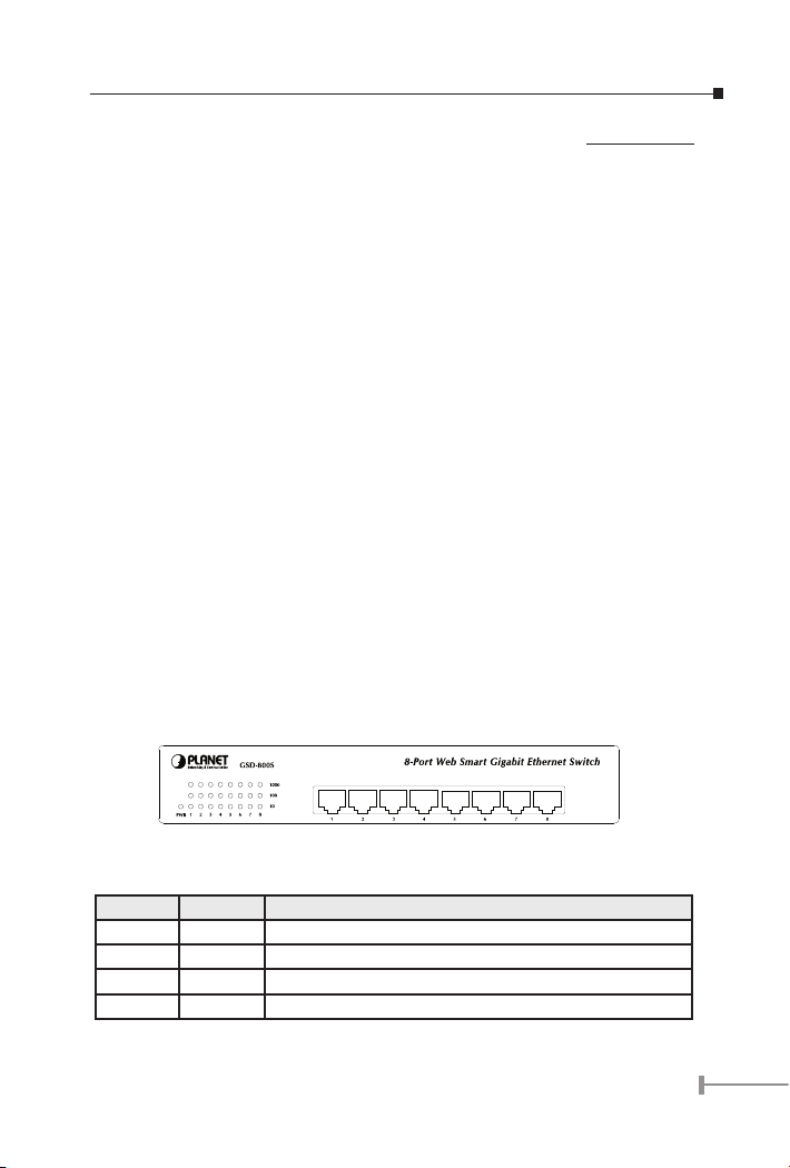
2.1.2 GSD-800S Front Panel
Figure 2-1 shows the front panel of GSD-800S
2.1.3 LED Indicators
LED Color Function
PWR Green Light: Power on
1000 Green Light: The port is operation at 1000Mbps speed
100 Green Light: The port is operation at 100Mbps speed
10 Green Light: The port is operation at 10Mbps speed
5
7
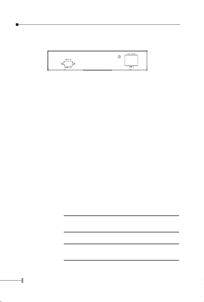
2.1.4 GSD-800S rear panel
The rear panel of the Switch indicates an AC inlet power socket, which accepts input
power from 100 to 240VAC, 50-60Hz.
Figure 2-2 Rear Panel of GSD-800S
Power Notice:
1. The device is a power-required device, it means, it will not work till it is powered. If your networks should active all the time, please consider using UPS
(Uninterrupted Power Supply) for your device. It will prevent you from network
data loss or network downtime.
2. In some area, installing a surge suppression device may also help to protect
your switch from being damaged by unregulated surge or current to the Switch
or the power adapter.
2.2 Installing a GSD-800S
This part describes how to install your GSD-800S Gigabit Ethernet Switch and make
connections to the switch. Please read the following topics and perform the procedures in
the order being presented.
PLANET GSD-800S Gigabit Ethernet Switch do not need software conguration. To install
your GSD-800S on a desktop or shelf, simply complete the following steps.
2.2.1 Desktop Installation
To install a GSD-800S on a desktop or shelf, simply complete the following steps:
Step1: Attach the rubber feet to the recessed areas on the bottom of the switch.
Step2: Place the GSD-800S on a desktop or shelf near an AC power source.
Optional rack-ear for 10-inch cabinet rack mounting (RKE-10A)
NOTE:
Step3: Keep enough ventilation space between the switch and the surrounding objects
NOTE:
Step4: Connect your GSD-800S to network devices
and 19-inch cabinet rack mounting (RKE-10B) is available upon
request.
When choosing a location, please keep in mind the environmental restrictions discussed in Chapter 1, Section 4, Product
Specication.
6

A. Connect one end of a standard network cable to the 10/100/1000 RJ-45 ports
on the front of the GSD-800S.
B. Connect the other end of the cable to the network devices such as printer serv-
ers, workstations or routers etc.
Connection to the Switch requires UTP Category 5 network
NOTE:
Step5: Supply power to the Switch.
A. Connect one end of the power cable to the GSD-800S
B. Connect the power plug of the power cable to a standard wall outlet.
When the GSD-800S receives power, the Power LED should remain solid Green.
cabling with RJ-45 tips. For more information, please see the
Cabling Specication in Section 4, Specication.
7
9
Chapter 3
CONFIGURATION
Unlike the unmanaged switch, GSD-800S performs series smart functions that make the
switch operate more effectively. This section will describe the common usage of the Switch
Smart Con-guration.
3.1 Preparing for conguration
3.1.1 Connecting a PC or Terminal to the RS-232 Port
When you are ready to congure the smart functions of the switch, make sure you had
connected the supplied RS-232 serial cable to the RS-232 port at the front panel of your
GSD-800S Switch and your PC.
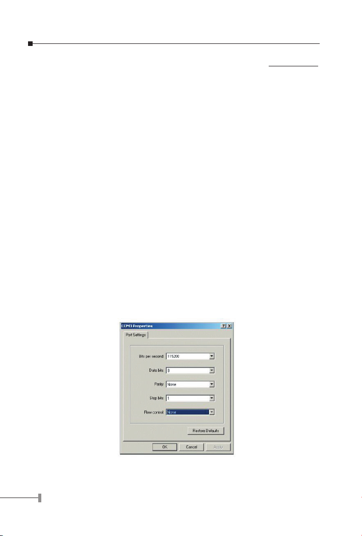
3.1.2 Terminal Emulation Setup Program
In Windows 98/2000/XP, launch “HyperTerminal”, create a new connection, and adjust
settings as below:
● Emulation: VT-100 compatible
● Baud per second: 115200
● Data bits: 8
● Parity: None
● Stop bits: 1
● Flow Control: None
To gain a demo, please see the Figure 3-1.
Figure 3-1 Console Configuration
8

3.1.3 Login
Login is required to access the command console after the system start up successfully.
The factory default password is “admin”. You may change it in the Console command
group. To access to the Console interface, please always enter the correct password. (See
Figure 3-2)
Figure 3-2 GSD-800S Login Screen
3.2 General
3.2.1 Command Hierarchy
The CLI is hierarchical with two levels: a top level and a group level. The group level
consists of the following groups:
● System
● Console
● Port
● MAC
● VLAN
● Aggr
● QoS
● Mirror
● IP
At top level you may enter a command and by giving the full command string, including
group, or you may change context into a group by entering the name of the group.
At group level you may enter commands for the particular group you have chosen
without specifying the group name or you may return to the top level by entering the up
command. The current level and group is indicated by the prompt. If you are at the top
level, the prompt will be:
>
9

11
If you are at group level, the prompt will display the actual group, e.g.
System>
At group level you also have the option of using the slash (/) key to refer to a context
relative to the top level. E.g. you may be in the system group and enter a /console
command into the console group.
3.2.2 Login/Logout Procedures
To get access to the CLI you must login by entering a password. You will automatically
be queried about the password. The password is congurable. The password check may
be disabled by setting the password to an empty string , in which case any password
entered during login will be accepted.
You may logout at any time and at any context level using the exit command.
3.2.3 Help Utility
You may get help by pressing the ? key or entering help. The help info depends on the
context:
● At top level, a list of command groups is displayed.
● At group level, a list of the command syntaxes for the current group is displayed.
● If the help command is issued for a specific command, the command syntax
and a description of the command are shown.
3.2.4 Example
The command hierarchy and the help utility is demonstrated in the following example:
> ? <enter>
Commands at top level:
System – System commands
Console – Console commands
Port – Port commands
MAC - MAC table commands
VLAN – VLAN commands
Aggregation – Aggregation/Trunking commands
QoS – QoS commands
Mirror – Mirror commands
IP – IP commands
10

console <enter>
Console> ? <enter>
Commands at Console level:
Console Configuration
Console Password [<password>]
Console Timeout [<timeout>]
Console Prompt [<prompt string>]
------
Up
Console> password ?
Syntax:
Console Password [<password>]
Description:
Set or display console password. The empty string ("") disables the password
check.
[<password>]: Password string of up to 16 characters.
Console>
3.2.6 Terminology
The following table shows general parameter types used in command syntaxes and
descriptions.
<port> Port identifier: Any number in the range 1-8.
<portlist> Comma and/or dash separated port list. This type can be used
for specifying individual ports or a range of ports. The keyword
none can be used to specify an empty port list. The keyword
all can be used to specify all ports. Example: 1,3,8-12
<macaddress> MAC Address; format: hh-hh-hh-hh-hh-hh , hh:hh:hh:hh:
hh:hh or hhhhhhhhhhhh . The hh is Hexadecimal number in
the range 0x00 to 0xFF. Example: 00-00-24-F1-02-03
11

13
<vid> VLAN ID: Decimal number in the range 1-8. The keyword all
can be used to specify all VLAN IDs.
<vidlist> Comma and/or dash separated VLAN ID list. This type can be
used for specifying individual VLAN IDs or a range of VLAN
IDs. The keyword none can be used to specify an empty
VLAN ID list. Example: 1,2,4-6
<class> Internal class of service.4 queues: low | normal | medium |
high
The <portlist> type is very useful when setting up multiple ports in the same mode. For
example, the following commands will divide the ports into two untagged VLANs:
vlan add 1 1-4
vlan add 2 5-7
vlan pvid 1-4 1
vlan pvid 5-7 2
3.3 Commands
3.3.1 System s Commands
System Conguration
Syntax:
System Conguration [all]
Description:
Show system name, software version, hardware version and management
MAC address. Optionally show the full conguration
[all]: Show the total switch conguration (default: System conguration only).
System Restore Default
Syntax:
System Restore Default [keepIP]
Description:
Restore factory default conguration.
[keepIP]: Preserve IP conguration (default: Not preserved).
System Name
Syntax:
12

System Name [<name>]
Description:
Set or show the system name. The empty string ( ) clears the system name.
[<name>]: String of up to 16 characters (default: Show system name).
System Reboot
Syntax:
System Reboot
Description:
Reboot the switch.
System SNMP
Syntax:
System SNMP [enable|disable]
Description:
Activate or deactivate SNMP.
[enable|disable]: Enable/disable SNMP (default: Show SNMP mode).
3.3.2 Console Commands
Console Conguration
Syntax:
Console Conguration
Description:
Show congured console password and timeout.
Console Password
Syntax:
Console Password [<password>]
Description:
Set or show the console password. The empty string ( ) disables the password
check.
[<password>]: Password string of up to 16 characters.
13

15
Console Timeout
Syntax:
Console Timeout [<timeout>]
Description:
Set or show the console inactivity timeout in seconds. The value zero disables
timeout.
[<timeout>]: Timeout value in seconds, 0, 60-10000.
Console Prompt
Syntax:
Console Prompt [<prompt_string>]
Description:
Set or show the console prompt string. The empty string ( ) clears the prompt
string.
[<prompt_string>]: Command prompt string of up to 10 characters.
3.3.3 Port Commands
Port Conguration
Syntax:
Port Conguration [<portlist>]
Description:
Show the congured and current speed, duplex mode, ow control mode and
state for the port.
<portlist>: Port list (Default: All ports).
Port Mode
Syntax:
Port Mode [<portlist>] [<mode>]
Description:
Set or show the speed and duplex mode for the port.
<portlist>: Port list (Default: All ports).
<mode> : Port speed and duplex mode (Default: Show congured and current mode).
14

10hdx: 10 Mbit/s, half duplex.
10fdx: 10 Mbit/s, full duplex.
100hdx: 100 Mbit/s, half duplex.
100fdx: 100 Mbit/s, full duplex.
1000fdx: 1 Gbit/s, full duplex.
auto: Auto negotiation of speed and duplex.
Port Flow Control
Syntax:
Port Flow Control [<portlist>] [enable|disable]
Description:
Set or show ow control mode for the port.
<portlist>: Port list (default: All ports).
[enable|disable]: Enable/disable ow control (default: Show ow control mode).
Port State
Syntax:
Port State [<portlist>] [enable/disable]
Description:
Set or show the state for the port.
<portlist>: Port list (default: All ports).
[enable|disable]: Enable or disable port state (default: Show state).
Port MaxFrame
Syntax:
Port MaxFrame [<portlist>] [<framesize>|reset]
Description:
Set or show the maximum frame size in bytes (including FCS) for frames received on the port. Tagged frames are allowed to be 4 bytes longer than the
maximum frame size. Use the reset option to return to the default setting.
[<portlist>] : Port list (default: All ports).
[<framesize>|reset]: Maximum frame size or reset to 9600 bytes (default: Show
15

17
maximum frame size).
Port Statistics
Syntax:
Port Statistics [<portlist>] [clear]
Description:
Show or clear statistics for the port.
<portlist>: Port list (default: All ports).
[clear] : Clear port statistics (default: Show statistics).
3.3.4 MAC Table Commands
MAC Conguration
Syntax:
MAC Conguration
Description:
Show the permanently stored MAC table and the MAC ageing timer.
MAC Add
Syntax:
MAC Add <macaddress> <portlist>|none [<vid>]
Description:
Add a static MAC address table entry and VLAN ID on ports.
<macaddress>: MAC address, 12-digit hex string, optionally separated with dashes or
colons (e.g. 010203ABCDEF or 01-02-03-AB-CD-EF or 01:02:03:AB:CD:EF).
<portlist> : Port list. Use none to specify no ports.
[<vid>] : VLAN ID, 1-8 (default: 1).
Note: Maximum 16 MAC addresses can be added.
MAC Delete
Syntax:
MAC Delete <macaddress> [<vid>]
Description:
16

Delete MAC address and VLAN ID.
<macaddress>: MAC address, 12-digit hex string, optionally separated with dashes or
colons (e.g. 010203ABCDEF or 01-02-03-AB-CD-EF or 01:02:03:AB:CD:EF).
[<vid>] : VLAN ID (default: 1).
MAC Lookup
Syntax:
MAC Lookup <macaddress> [<vid>]
Description:
Lookup MAC address and VLAN ID.
<macaddress>: MAC address, 12-digit hex string, optionally separated with dashes or
colons (e.g. 010203ABCDEF or 01-02-03-AB-CD-EF or 01:02:03:AB:CD:EF).
[<vid>] : VLAN ID, 1-8 (default: 1).
MAC Flush
Syntax:
MAC Flush
Description:
Removes non-static MAC address table entries.
MAC Age Time
Syntax:
MAC Agetime [<agetime>]
Description:
Set or show the MAC age timer in seconds. The value zero disables ageing.
[<agetime>]: Age timer in seconds, 0 or 10-65535 (default: Show timer).
3.3.5 VLAN Commands
VLAN Conguration
Syntax:
VLAN Conguration [<portlist>]
Description:
17

19
Show the VLAN mode, port VLAN ID and accepted frame type for the port and
the permanently stored VLAN table.
[<portlist>]: Port list (default: All ports).
VLAN Add
Syntax:
VLAN Add <vidlist> [<portlist>]
Description:
Add VLAN entry and include ports in member set.
<vidlist> : VLAN ID list.
[<portlist>]: Port list (default: All ports).
VLAN Delete
Syntax:
VLAN Delete <vidlist>
Description:
Delete VLAN entry (all ports excluded from member set).
<vidlist> : VLAN ID list.
VLAN Lookup
Syntax:
VLAN Lookup <vidlist>
Description:
Lookup VLAN entry and show port list.
<vidlist> : VLAN ID list.
VLAN PVID
Syntax:
VLAN PVID [<portlist>] [<vid>|none]
Description:
Set or show the port VLAN ID. Untagged frames received on the port will be
classied to this VLAN ID. Frames classied to this VLAN ID will be sent un-
18

tagged on the port.
[<portlist>]: Port list (default: All ports).
[<vid>|none]: Port VLAN ID, 1-8 (default: Show PVID). The none option can be used
for trunk links.
3.3.6 Aggregation/trunking Commands
Aggregation Conguration
Syntax:
Aggr Conguration
Description:
Shows the aggregation groups and the aggregation mode.
Aggregation Add
Syntax:
Aggr Add <portlist>
Description:
Add link aggregation group including ports.
<portlist>: Aggregation port list.
Aggregation Delete
Syntax:
Aggr Delete <portlist>
Description:
Delete link aggregation group.
<portlist>: Port list. Aggregations including any of the ports will be deleted.
Aggregation Lookup
Syntax:
Aggr Lookup <portlist>
Description:
Lookup and display link aggregation group.
19

21
<portlist>: Port list. Aggregations including any of the ports will be shown.
Aggregation Mode
Syntax:
Aggr Mode [smac|dmac|xor]
Description:
Set or show link aggregation trafc distribution mode.
[smac|dmac|xor]: Aggregation mode, SMAC, DMAC or XOR (default: Show mode).
3.3.7 QoS Commands
QoS Conguration
Syntax:
QoS Conguration [<portlist>]
Description:
Show the congured QoS mode, IP DSCP Precedence priority mapping for
the port.
[<portlist>] : Port list (default: All ports).
QoS Mode
Syntax:
QoS Mode [<portlist>] [tag|port|diffserv]
Description:
Set or show the priority mode for the port.
[<portlist>] : Port list (default: All ports).
[tag|port|diffserv]: Enable tag IP differentiated services for the port (default: Show
mode).
QoS Default
Syntax:
QoS Default [<portlist>] [<class>]
Description:
Set or show the default class. In tag mode, the default class is used for un-
20

tagged frames. In port mode, the default class is used as the port priority. In
the other modes, the default class is used for non-IP frames and IP frames
with options.
[<portlist>]: Port list (default: All ports).
[<class>] : Internal class of service (default: Show class).
QoS Tagprio
Syntax:
QoS Tagprio [<portlist>] [<tagpriolist>] [<class>]
Description:
Set or show the VLAN user priority mapping.
[<portlist>] : Port list (default: All ports).
[<tagpriolist>]: VLAN user priority list, 0-7 (default: All user priorities). [<class>] :
Internal class of service (default: Show class).
QoS DiffServ
Syntax:
QoS DiffServ [<dscplist>] [<class>]
Description:
Set or show the IP Differentiated Services mapping.
[<dscplist>]: IP DSCP list, 0-63 (default: All DSCP values).
[<class>] : Internal class of service (default: Show class).
3.3.8 Mirror Commands
Mirror Conguration
Syntax:
Mirror Conguration
Description:
Show the mirror destination port and mirror mode for source ports.
Mirror Port
Syntax:
21

23
Mirror Port [<port>]
Description:
Set or show the mirror destination port.
[<port>]: Mirror destination port (default: Show mirror port).
Mirror Source
Syntax:
Mirror Source [<portlist>] [enable|disable]
Description:
Set or show the source port mirror mode.
[<portlist>]: Source port list (default: All ports).
[enable|disable]: Enable/disable mirroring of frames received on port (default: Show
mirror mode).
3.3.9 IP Commands
IP Conguration
Syntax:
IP Conguration
Description:
Show congured IP address, mask, gateway, VLAN ID and mode.
IP Setup
Syntax:
IP Setup [ipaddress> [<ipmask> [ipgateway>]]] [<vid>]
Description:
Set or show IP conguration.
[<ipaddress>]: IP address (default: Show IP conguration).
[<ipmask>] : IP subnet mask (default: Subnet mask for address class).
[<ipgateway>]: Default IP gateway (default: 0.0.0.0). [<vid>] : VLAN ID, 1-8 (default:
1).
22

IP Mode
Syntax:
IP Mode [enable|disable]
Description:
Activate or deactivate the IP conguration.
[enable|disable]: Enable/disable IP (default: Show IP mode).
3.4 Examples
3.4.1 VLAN conguration
This example shows how to congure two VLANs with the following setup on at GSD800S:
● VID 1 spans ports 2-8 and VID 2 spans ports 1-3, so port 2 and 3 are members
of both VLANs.
● Port 1 is the access port for VID 2, so PVID of port 1 must be set to 2.
● Port 2 is the trunk port for VID 1 and VID 2, so the PVID of port 2 must be set
to none and port 2 must be set to accept tagged frames only.
● Port 3 is the hybrid port for VID 1 and VID 2, where VID 1 is the untagged
VLAN, so PVID must be set to 1.
● Ports 4-8 are access ports for VID 1.
The following CLI session does the above setup provided that the initial conguration is
the default conguration:
>vlan
VLAN>delete 1
VLAN>add 1 2-8
VLAN>add 2 1-3
VLAN>pvid 1 2
VLAN>pvid 2 none
VLAN>frame type 2 tagged
VLAN>conf
VLAN Configuration:
Port Aware PVID Frame Type
1: disabled 2 All
23

25
2: disabled none Tagged
3: disabled 1 All
4: disabled 1 All
5: disabled 1 All
6: disabled 1 All
7: disabled 1 All
8: disabled 1 All
Entries in permanent table:
1: 2,3,4,5,6,7,8
2: 1,2,3
VLAN>
24

Chapter 4
WEB Interface
From the WEB interface it is possible to, among other things:
● Set port mode.
● Enable/disable flow control.
● Configure simple port-based VLAN.
● Configure aggregation groups
● Configure QoS.
● Read and clear statistics counters.
● Upgrade software
All operations are password protected. The password must be entered at login. The
password is the same as is being used in the command line interface.
As stated in chapter 3 the IP mode is disabled in the factory default conguration.
To be able to use the WEB interface, the IP must be enabled and congured via the
command line interface. The IP address, mask and gateway must be set according to your
environment. Example on enabling the WEB interface via the command line interface:
>ip setup 192.168.0.100 255.255.252.0 192.168.0.254 1
>ip mode enable
4.1 Starting the Web Interface
Follow these steps to bring up the switch Web interface:
1. Enter the IP address of the switch in the Web browser address field.
2. Enter password. The password is the same as the CLI interface. Click on the
Apply button.
3. Make your selection by clicking on the item in menu frame.
25

27
Chapter 5
SWITCH OPERATION
5.1 Address Table
The Switch is implemented with an address table. This address table composed of many
entries. Each entry is used to store the address information of some node in network,
including MAC address, port no, etc. This in-formation comes from the learning process
of Ethernet Switch.
5.2 Learning
When one packet comes in from any port, the Switch will record the source address, port
no. And the other related information in address table. This information will be used to
decide either forwarding or ltering for future packets.
5.3 Forwarding & Filtering
When one packet comes from some port of the Ethernet Switching, it will also check
the destination address besides the source address learning. The Ethernet Switching will
lookup the address-table for the destination address. If not found, this packet will be
forwarded to all the other ports except the port, which this packet comes in. And these
ports will transmit this packet to the network it connected. If found, and the destination
address is located at different port from this packet comes in, the Ethernet Switching will
forward this packet to the port where this destination address is located according to the
information from address table. But, if the destination address is located at the same port
with this packet comes in, then this packet will be ltered. Thereby increasing the network
throughput and availability.
5.4 Store-and-Forward
Store-and-Forward is one type of packet-forwarding techniques. A Store-and-Forward
Ethernet Switching stores the incoming frame in an internal buffer, do the complete error
checking before transmission. Therefore, no error packets occurrence, it is the best choice
when a network needs efciency and stability.
The Ethernet Switch scans the destination address from the packet-header, searches the
routing table pro-vided for the incoming port and forwards the packet, only if required. The
fast forwarding makes the switch attractive for connecting servers directly to the network,
thereby increasing throughput and availability. How-ever, the switch is most commonly
used to segment existence hubs, which nearly always improves overall performance. An
Ethernet Switching can be easily congured in any Ethernet network environment to
signicantly boost bandwidth using conventional cabling and adapters.
Due to the learning function of the Ethernet switching, the source address and
corresponding port number of each incoming and outgoing packet are stored in a routing
table. This information is subsequently used to lter packets whose destination address is
on the same segment as the source address. This connes network trafc to its respective
domain and reduce the overall load on the network.
The Switch performs “Store and forward” therefore, no error packets occur. More reliably,
it reduces the re-transmission rate. No packet loss will occur.
26

5.5 Auto-Negotiation
The STP ports on the Switch have built-in “Auto-negotiation”. This technology automatically
sets the best possible bandwidth when a connection is established with another network
device (usually at Power On or Reset). This is done by detect the modes and speeds at
the second of both device is connected and capable of, both 10Base-T and 100Base-TX
devices can connect with the port in either Half- or Full-Duplex mode.
If attached device is: 1000Base-T port will set to:
10Mbps, no auto-negotiation 10Mbps
10Mbps, with auto-negotiation 10/20Mbps (10Base-T/Full-Duplex)
100Mbps, no auto-negotiation 100Mbps
100Mbps, with auto-negotiation 100/200Mbps (100Base-TX/Full-Duplex)
1000Mbps with auto-negotiation 2000Mbps (1000Mbps/Full-Duplex)
27

29
Chapter 6
TROUBLE SHOOTING
This chapter contains information to help you solve problems. If the Ethernet Switch is not
functioning properly, make sure the Ethernet Switch was set up according to instructions
in this manual.
The Link LED is not lit
Solution:
Check the cable connection and remove duplex mode of the Ethernet Switch
Some stations cannot talk to other stations located on the other port
Solution:
Please check the VLAN settings, trunk settings, or port enabled / disabled
status.
Performance is bad
Solution:
Check the full duplex status of the Ethernet Switch. If the Ethernet Switch is
set to full duplex and the partner is set to half duplex, then the performance
will be poor. Please also check the in/out rate of the port.
Why the Switch doesn’t connect to the network
Solution:
● Check the LNK/ACT LED on the switch
● Try another port on the Switch
● Make sure the cable is installed properly
● Make sure the cable is the right type
● Turn off the power. After a while, turn on power again
28

APPENDEX A
Switch’s RJ-45 Pin Assignments
A.1 1000Mbps, 1000Base T
Contact MDI MDI-X
1 BI_DA+ BI_DB+
2 BI_DA- BI_DB-
3 BI_DB+ BI_DA+
4 BI_DC+ BI_DD+
5 BI_DC- BI_DD-
6 BI_DB- BI_DA-
7 BI_DD+ BI_DC+
8 BI_DD- BI_DC-
Implicit implementation of the crossover function within a twisted-pair cable, or at a
wiring panel, while not expressly forbidden, is beyond the scope of this standard.
A.2 10/100Mbps, 10/100Base-TX
When connecting your 10/100Mbps Ethernet Switch to another switch, a bridge or a hub,
a straight or crossover cable is necessary. Each port of the Switch supports auto-MDI/
MDI-X detection. That means you can directly connect the Switch to any Ethernet devices
without making a crossover cable. The following table and diagram show the standard
RJ-45 receptacle/ connector and their pin assignments:
RJ-45 Connector pin assignment
MDI
Contact
1 Tx + (transmit) Rx + (receive)
2 Tx - (transmit) Rx - (receive)
3 Rx + (receive) Tx + (transmit)
4, 5 Not used
6 Rx - (receive) Tx - (transmit)
7, 8 Not used
Media Dependant
Interface
MDI-X
Media Dependant
Interface -Cross
29

The standard cable, RJ-45 pin assignment
The standard RJ-45 receptacle/connector
There are 8 wires on a standard UTP/STP cable and each wire is color-coded. The following
shows the pin allocation and color of straight cable and crossover cable connection:
Figure A-1: Straight-Through and Crossover Cable
Please make sure your connected cables are with same pin assignment and color as above
picture before deploying the cables into your network.
30


Part NO.:2010-A35040-000
 Loading...