

Page 1

FGSW-2620VM / FGSW-2624SF User’s Manual
FGSW-2620VM
24-Port 10/100Mbps with
User's Manual
2G TP/SFP Combo
Managed Ethernet Switch
FGSW-2624SF
24 100Base-FX SFP Slots with
2G TP/SFP Combo
Managed Ethernet Switch
1
Page 2

FGSW-2620VM / FGSW-2624SF User’s Manual
Trademarks
Copyright © PLANET Technology Corp. 2008.
Contents subject to which revision without prior notice.
PLANET is a registered trademark of PLANET Technology Corp. All other trademarks belong to their respective
owners.
Disclaimer
PLANET Technology does not warrant that the hardware will work properly in all environments and applications, and
makes no warranty and representation, either implied or expressed, with respect to the quality, performance,
merchantability, or fitness for a particular purpose.
PLANET has made every effort to ensure that this User's Manual is accurate; PLANET disclaims liability for any
inaccuracies or omissions that may have occurred.
Information in this User's Manual is subject to change without notice and does not represent a commitment on the part of
PLANET. PLANET assumes no responsibility for any inaccuracies that may be contained in this User's Manual. PLANET
makes no commitment to update or keep current the information in this User's Manual, and reserves the right to make
improvements to this User's Manual and/or to the products described in this User's Manual, at any time without notice.
If you find information in this manual that is incorrect, misleading, or incomplete, we would appreciate your comments
and suggestions.
FCC Warning
This equipment has been tested and found to comply with the limits for a Class A digital device, pursuant to Part 15 of
the FCC Rules. These limits are designed to provide reasonable protection against harmful interference when the
equipment is operated in a commercial environment. T his equipment gene rates, uses, and can radiate r adio frequency
energy and, if not installed and used in accordance with the Instruction manual, may cause harmful interference to radio
communications. Operation of this equipment in a residential area is likely to caus e harmful interference in which cas e
the user will be required to correct the interference at whose own expense.
CE Mark Warning
This is a Class A product. In a domestic environment, this product may cause radio interference, in which case the user
may be required to take adequate measures.
WEEE Warning
To avoid the potential effects on the environment and human health as a result of the presence of
hazardous substances in electrical and electronic equipment, end users of electrical and electronic
equipment should understand the meaning of the crossed-out wheeled bin symbol. Do not dispose
of WEEE as unsorted municipal waste and have to collect such WEEE separately.
Revision
PLANET Managed Ethernet Switch User's Manual
FOR MODELS: FGSW-2620VM / FGSW-2624SF(v2)
REVISION: 1.1 (AUGUST.2008)
Part No.: 2080-A92350-002
2
Page 3

FGSW-2620VM / FGSW-2624SF User’s Manual
Table of Contents
1. INTRODUCTION ........................................................................................................... 6
1.1 PACKET CONTENTS................................................................................................................................... 6
1.2 HOW TO USE THIS MANUAL....................................................................................................................... 6
1.3 PRODUCT FEATURE ..................................................................................................................................7
1.4 PRODUCT SPECIFICATION..........................................................................................................................8
2. INSTALLATION...........................................................................................................10
2.1 PRODUCT DESCRIPTION..........................................................................................................................10
2.1.1 Product Overview ...........................................................................................................................................10
2.1.2 Switch Front Panel..........................................................................................................................................11
2.1.3 LED Indications...............................................................................................................................................11
2.1.4 Switch Rear Panel ..........................................................................................................................................13
2.2 INSTALL THE SWITCH...............................................................................................................................14
2.2.1 Desktop Installation.........................................................................................................................................14
2.2.2 Rack Mounting................................................................................................................................................14
2.2.3 Installing the SFP transceiver .........................................................................................................................16
3. SWITCH MANAGEMENT............................................................................................19
3.1 ABOUT WEB-BASED MANAGEMENT ..........................................................................................................19
3.2 REQUIREMENTS......................................................................................................................................19
3.3 PREPARING FOR WEB MANAGEMENT....................................................................................................... 20
3.4 SYSTEM LOGIN.......................................................................................................................................20
3.5 ONLINE HELP .........................................................................................................................................22
3.6 VIEW THE PORT INFORMATION................................................................................................................. 22
4. WEB-BASED MANAGEMENT....................................................................................23
4.1 SYSTEM .................................................................................................................................................23
4.1.1 System Information.........................................................................................................................................23
4.1.1.1 Basic.....................................................................................................................................................23
4.1.1.2 Advanced..............................................................................................................................................24
4.1.2 IP Configuration..............................................................................................................................................25
4.1.3 Account Password ..........................................................................................................................................26
4.1.4 SNMP Management........................................................................................................................................27
4.1.4.1 System Configuration ...........................................................................................................................27
4.1.4.2 Trap Configuration................................................................................................................................28
4.1.5 TFTP Upgrade................................................................................................................................................29
3
Page 4

FGSW-2620VM / FGSW-2624SF User’s Manual
4.1.6 Factory Default ...............................................................................................................................................29
4.1.7 System Reboot ...............................................................................................................................................30
4.2 PORT CONFIGURATION............................................................................................................................ 31
4.2.1 Port Control.....................................................................................................................................................31
4.2.2 Port Mirror.......................................................................................................................................................33
4.2.3 Bandwidth Control ..........................................................................................................................................34
4.2.4 Port Statistics..................................................................................................................................................35
4.2.5 Port Trunk.......................................................................................................................................................36
4.2.5.1 Aggregator setting.................................................................................................................................36
4.2.5.2 Aggregator Information .........................................................................................................................37
4.2.5.3 Aggregator State Activity.......................................................................................................................38
4.3 SWITCHING.............................................................................................................................................39
4.3.1 VLAN ..............................................................................................................................................................39
4.3.1.1 VLAN configuration...............................................................................................................................42
4.3.1.2 802.1Q Ingress Filter............................................................................................................................ 47
4.3.2 Rapid Spaning Tree ........................................................................................................................................48
4.3.2.1 System Configuration ...........................................................................................................................54
4.3.2.2 Per Port Configuration..........................................................................................................................55
4.3.3 IGMP Snooping ..............................................................................................................................................56
4.3.4 Forwarding Table ............................................................................................................................................ 59
4.4 QOS......................................................................................................................................................60
4.4.1 QoS Configuration ..........................................................................................................................................60
4.5 SECURITY...............................................................................................................................................62
4.5.1 802.1x/Radius................................................................................................................................................. 63
4.5.1.1 System Configuration ...........................................................................................................................66
4.5.1.2 Per port Configuration...........................................................................................................................68
4.5.1.3 802.1X Client Configuration..................................................................................................................70
4.5.1.4 Misc Configuration................................................................................................................................73
4.5.2 Access Control List.........................................................................................................................................74
4.5.3 Static MAC Address........................................................................................................................................75
4.5.4 MAC Filter.......................................................................................................................................................76
4.5.5 IP Secuity........................................................................................................................................................77
5. SWITCH OPERATION.................................................................................................78
5.1 ADDRESS TABLE.....................................................................................................................................78
5.2 LEARNING ..............................................................................................................................................78
5.3 FORWARDING & FILTERING...................................................................................................................... 78
5.4 STORE-AND-FORWARD ...........................................................................................................................78
4
Page 5

FGSW-2620VM / FGSW-2624SF User’s Manual
5.5 AUTO-NEGOTIATION................................................................................................................................79
6. TROUBLESHOOTING ................................................................................................80
6.1 INCORRECT CONNECTIONS ......................................................................................................................80
6.2 DIAGNOSING LED INDICATORS................................................................................................................80
APPENDIX A: CABLE PIN ASSIGNMENT.....................................................................81
7.1 CABLE.................................................................................................................................................... 81
7.2 100BASE-TX/10BASE-T PIN ASSIGNMENTS.......................................................................................... 81
7.3 RJ-45 CABLE PIN ASSIGNMENT ................................................................................................................82
APPENDIX B : ACCESS CONTROL LIST APPLICATION GUIDE ................................83
Before the ACL Configure … ...................................................................................................................................84
Case 1: Deny specific Source IP Address – Host....................................................................................................85
Case 2: Deny specific Source IP Address – Class C...............................................................................................87
Case 3: Deny specific VLAN packets.......................................................................................................................89
Case 4: Deny Specify Protocol – HTTP / WWW......................................................................................................91
Case 5: Deny Specify Protocol – SMTP ..................................................................................................................93
5
Page 6

FGSW-2620VM / FGSW-2624SF User’s Manual
1. INTRODUCTION
1.1 Packet Contents
Check the contents of your package for following parts:
Fast Ethernet Managed Switch x1
CD-ROM user's manual x1
Quick installation guide x1
19" rack mounting kit x1
Power cord x1
Rubber feet x 4
If any of these are missing or damaged, please contact your dealer immediately, if possible, retain the carton including
the original packing material, and use them against to repack the product in case there is a need to return it to us for
repair.
1.2 How to Use This Manual
This User Manual is structured as follows:
Chapter 2, Installation
The chapter explains the functions of the Switch and how to physically install the Switch.
Chapter 3, SWITCH MANAGEMENT
The chapter explains how to manage the Switch.
Chapter 4, WEB-BASED MANAGEMENT
The chapter explains how to manage the Switch by Web interface.
Chapter 5, Switch Operation
The chapter explains how the Switch with Layer 2 operation does.
Chapter 6, TROUBLE SHOOTING
The chapter explains how to trouble shooting of the Switch.
APPENDIX, CABLE PIN ASSIGNMENT
The chapter contains cable information of the Switch.
In the following section, terms “Managed Switch” with upper case denote the FGSW-2620VM / FGSW-2624SF
Ethernet Switch. Terms with lower case "switch" means any Ethernet switches.
6
Page 7

1.3 Product Feature
¾ Physical Ports
FGSW-2620VM
■ 24-Port 10/100Mbps Fast Ethernet ports
■ 2 10/100/1000Mbps TP and SFP shared combo interfaces
■ Reset button for system management
FGSW-2624SF
■ 24-Port 100Base-FX SFP Fast Ethernet slots
■ 2 10/100/1000Mbps TP and SFP shared combo interfaces
■ Reset button for system management
¾ Layer 2 Features
FGSW-2620VM / FGSW-2624SF User’s Manual
■ Complies with the IEEE 802.3, IEEE 802.3u, IEEE 802.3z and IEEE 802.3ab Gigabit Ethernet standard
■ Each Switching ports support auto-negotiation-10/20, 100/200Mbps supported
■ Auto-MDI/MDI-X detection on each RJ-45 port
■ Prevents packet loss with back pressure (Half-Duplex) and 802.3x PAUSE frame Flow Control (Full-Duplex)
■ High performance Store and Forward architecture, broadcast storm control, runt/CRC filtering eliminates
erroneous packets to optimize the network bandwidth
■ 8K MAC address table, automatic source address learning and ageing
■ Port-Based VLAN and IEEE 802.1Q Tagged VLAN
■ IEEE 802.3ad Port trunk with LACP and Static Port Trunk
■ IEEE 802.1w Spanning tree protocol
■ IGMP snooping and IGMP Query mode for Multi-media application
■ Broadcast storm filter
■ Port mirroring allows monitoring of the traffic across any port in real time
¾ Quality of Service
■ Supports QoS and bandwidth control on each port
■ IEEE 802.1p class of service ; support Strict and WRR mode
¾ Security
■ Supports Access Control List function
■ MAC Filter and Static MAC
■ IP Security for management security
■ IEEE 802.1x Port-Based authentication
¾ Management
■ Web interface for Switch basic management and setup
■ Supports SNMP v1 switch management
■ SNMP trap for interface Link Up and Link Down notification
7
Page 8
FGSW-2620VM / FGSW-2624SF User’s Manual
■ 19-inch rack mount size
■ EMI standards comply with FCC, CE class A
1.4 Product Specification
Product FGSW-2620VM FGSW-2624SF
Hardware Specification
10/100Mbps Ports
1000Mbps Copper ports
SFP/mini-GBIC Slots
Switch Processing Scheme
Throughput (packet per
second)
Switch fabric
Address Table
Share data Buffer
Maximum Frame Size
Flow Control
Dimensions
Weight
Power Requirement
Power Consumption /
Dissipation
Temperature
Humidity Operating:
Layer 2 Function
Management Interface
Port Configuration
Port Status
Trunk Configuration
VLAN Configuration
Spanning Tree Protocol
Port Monitoring
24 10/100Base-TX RJ-45
Auto-MDI/MDI-X ports
2 10/100/1000Base-T RJ-45, Auto-MDI/MDI-X ports
2 1000Base-SX/LX SFP slots, shared with Port-25 and Port-26
Store-and-Forward
6.547Mpps
8.8Gbps
8K entries
512K Bytes
1522 Bytes
Back pressure for Half-Duplex
IEEE 802.3x Pause Frame for Full-Duplex
440 x 120 x 44 mm, 1U height 440 x 220 x 44 mm, 1U height
1.87kg 2.6kg
100~240V AC, 50-60 Hz 100~240V AC, 50-60 Hz
13.5 Watts maximum / 46 BTU/hr
maximum
Operating: 0~50 degree C, Storage -40~70 degree C
10% to 90%, Storage: 5% to 95% (Non-condensing)
Web Browser
SNMP Monitor, SNMP Trap
Per port disable/enable,
Auto-negotiation disable/enable
Flow control disable/enable
Bandwidth control on each port
Display per port’s disable/enable status
Per port’s link status and speed duplex mode
Flow control status
Static Port Trunk
IEEE 802.3ad LACP (Link Aggregation Control Protocol)
Support 13 groups of maximum 8-Port trunk
IEEE 802.1Q Tag-Based VLAN
Port-based VLAN
Supports maximum up to 26 VLAN groups
IEEE 802.1W Rapid Spanning Tree
One Mirroring port to monitor one mirrored port. The monitor modes are RX, TX
and RX & TX
24 100Base-FX SFP slots
23.1 Watts maximum / 78 BTU/hr
maximum
8
Page 9
FGSW-2620VM / FGSW-2624SF User’s Manual
IGMP Snooping
QoS Configuration
Port counters
Rate Limit
Access Control List
Standards Conformance
Safety
Standards Compliance
The specification of FGSW-2624SF is for hardware version 2 only.
Supports v1 and v2 protocol
Supports IGMP Querier
4 priority queues per port
IEEE 802.1p CoS on each port
Port-Based priority
Display detail traffic counters on each port
Inbound Rate Limit and Outbound Traffic shaping; allow per 1Mbits setting
Supports up to 16 Access Control list groups
FCC Part 15 Class A, CE
IEEE 802.3
IEEE 802.3u
IEEE 802.3ab
IEEE 802.3z
IEEE 802.3x
IEEE 802.1Q
IEEE 802.1p
IEEE 802.1X
IEEE 802.1w
Ethernet
Fast Ethernet
Gigabit Ethernet
Gigabit Ethernet
Full-duplex flow control
Tag-Based VLAN
Class of service
Port-Based Authentication
Rapid Spanning Tree protocol
9
Page 10

FGSW-2620VM / FGSW-2624SF User’s Manual
2. INSTALLATION
This section describes the functionalities of the FGSW Managed Switch's components and guides how to install it on the
desktop or shelf. Basic knowledge of networking is assumed. Please read this chapter completely before continuin g.
2.1 Product Description
The PLANET FGSW Managed Switch offers 24 10/100Mbps Fast Ethernet ports or 24 100Base-FX SFP slots with 2
Gigabit TP/SFP combo ports (Port-25, 26). The two Gigabit TP/SFP combo ports can be either 1000Base-T for
10/100/1000Mbps or 1000Base-SX/LX through SFP (Small Factor Pluggable) interface. It boasts a high performance
switch architecture that is capable of providing non-blocking switch fabric and wire-speed throughput as high as
8.8Gbps. Its two built-in GbE uplink ports also offer incredible extensibility, flexibility and connectivity to the Core
switch or Servers.
With its built-in web-based management, the FGSW Managed Switch offers an easy-to-use, platform-independent
management and configuration facility. It supports standard Simple Network Management Protocol (SNMP) and can
be managed via any standard-based management software.
The IEEE 802 standard-based firmware provides a rich set of features and ensures interoperabilit y with equipment
from other vendors. Additionally, the firmware includes advanced features such as IGMP snooping, broadcast storm
control, Access Control List and MAC address filtering, to enhance security and bandwidth utilization.
For efficient management, the FGSW Managed Switch is equipped with web interface. It can be programmed for
basic switch management functions such as port speed configuration, Port Trunking, Port-based VLAN, Port Mirroring,
QoS, bandwidth control, Access Control list and Misc Configuration.
The FGSW Managed Switch provides port-based VLAN (including overlapping) and 802.1Q tag-based VLAN. The
VLAN groups allowed on the Managed Swith will be maximally up to 26 for port-based VLAN. Via supporting port
trunking, it allows the operation of a high-speed trunk combining multiple ports. The FGSW Managed Switch provides
13 groups of up to 8-ports for trunking and it supports fail-over as well.
2.1.1 Product Overview
With its built-in Web-based management, the PLANET FGSW Managed Switch offers an easy-to-use,
platform-independent management and configuration facility. It supports standard Simple Network Management
Protocol (SNMP) and can be managed via any standard-based management software.
10
Page 11
FGSW-2620VM / FGSW-2624SF User’s Manual
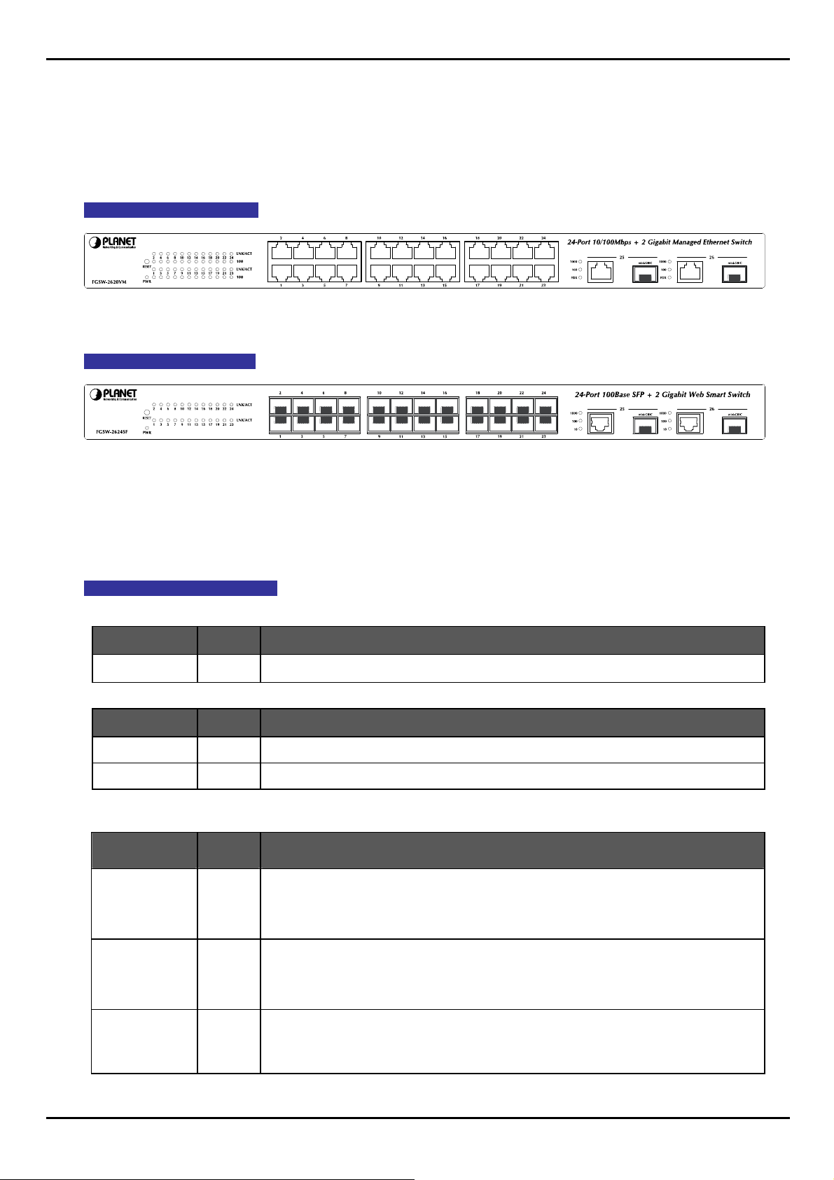
2.1.2 Switch Front Panel
The unit front panel provides a simple interface monitoring the Switch. Figure 2-1 to 2-2 shows the front panel of the
Managed Switches.
FGSW-2620VM Front Panel
Figure 2-1 FGSW-2620VM front panel.
FGSW-2624SF Front Panel
Figure 2-2: FGSW-2624SF Switch front panel
2.1.3 LED Indications
The front panel LEDs indicates instant status of port links, data activity and system power; helps monitor and
troubleshoot when needed.
FGSW-2620VM LED indication
System
LED Color Function
PWR Green Lights to indicate that the Switch has power.
Per 10/100Base-TX RJ-45 port
LED Color Function
LNK/ACT Green
100 Green
Per 10/100/1000Base-T port /SFP interfaces
LED Color Function
Lights to indicate the link through that port is successfully established.
Lights to indicate the port is running in 100Mbps speed.
LNK/ACT 1000 Green
LNK/ACT 100 Green
FDX Green
Lit: indicate that the port is operating at 1000Mbps.
Off: indicate that the port is operating at 10Mbps or 100Mbps.
Blink: indicate that the switch is actively sending or receiving data over that port.
Lit: indicate that the port is operating at 100Mbps.
Off: indicate that the port is operating at 10Mbps or 1000Mbps.
Blink: indicate that the switch is actively sending or receiving data over that port.
Lit: indicate that the port is operating at full-duplex mode.
Off: indicate that the port is operating at half-duplex mode.
11
Page 12
FGSW-2620VM / FGSW-2624SF User’s Manual
FGSW-2624SF LED indication
System
LED Color Function
PWR Green Lights to indicate that the Switch has power.
Per 100Base-FX SFP slot
LED Color Function
LNK/ACT Green
Lights to indicate the link through that port is successfully established.
Per 10/100/1000Base-T port /SFP interfaces
LED Color Function
Lit: indicate that the port is operating at 1000Mbps.
LNK/ACT 1000 Green
Off: indicate that the port is operating at 10Mbps or 100Mbps.
Blink: indicate that the switch is actively sending or receiving data over that port.
Lit: indicate that the port is operating at 100Mbps.
LNK/ACT 100 Green
Off: indicate that the port is operating at 10Mbps or 1000Mbps.
Blink: indicate that the switch is actively sending or receiving data over that port.
Lit: indicate that the port is operating at full-duplex mode.
FDX Green
Off: indicate that the port is operating at half-duplex mode.
1. Press the RESET button once. The t Switch will reboot automatically.
2. Press the RESET button for about 10 seconds. The Switch will back to the factory default
mode; the entire configuration will be erased.
3. The 2 Gigabit TP/SFP combo ports are shared with port 25/26 of FGSW-2620VM. Either of
them can operate at the same time.
12
Page 13

FGSW-2620VM / FGSW-2624SF User’s Manual
2.1.4 Switch Rear Panel
The rear panel of the Managed Switch indicates an AC inlet power socket, which accepts input power from 100 to 240V
AC, 50-60Hz. Figure 2-3 and Figure 2-4 shows the rear panel of the Switch
FGSW-2620VM Rear Panel
Figure 2-3 FGSW-2620VM Switch rear panel.
FGSW-2624SF Rear Panel
Figure 2-4: FGSW-2624SF Switch rear panel
Power Notice:
1. The device is a power-required device, it means, it will not work till it is powered. If your networks should active all
the time, please consider using UPS (Uninterrupted Power Supply) for your device. It will prevent you from net work
data loss or network downtime.
2. In some area, installing a surge suppression device may also help to protect your Switch from being damage d by
unregulated surge or current to the Switch or the power adapter.
13
Page 14
FGSW-2620VM / FGSW-2624SF User’s Manual
2.2 Install the Switch
This section describes how to install the Managed Switch and make connections to it. Please read the following topics
and perform the procedures in the order being presented.
2.2.1 Desktop Installation
To install the Managed Switch on desktop or shelf, please follows these steps:
Step1: Attach the rubber feet to the recessed areas on the bottom of the Managed Switch.
Step2: Place the Managed Switch on the desktop or the shelf near an AC power source.
Step3: Keep enough ventilation space between the Managed Switch and the surrounding objects.
When choosing a location, please keep in mind the envir onmental restrictions discussed in
Chapter 1, Section 4, in Specification.
Step4: Connect the Managed Switch to network devices.
A. Connect one end of a standard network cable to the 10/100/1000 RJ-45 ports on the front of the Managed
Switch
B. Connect the other end of the cable to the network devices such as printer servers, workstations or routers…etc.
Connection to the Managed Switch requires UTP Category 5 network cabling with RJ-45
tips. For more information, please see the Cabling Specification in Appendix A.
Step5: Supply power to the Managed Switch.
A. Connect one end of the power cable to the Managed Switch.
B. Connect the power plug of the power cable to a standard wall outlet.
When the Managed Switch receives power, the Power LED should remain solid Green.
2.2.2 Rack Mounting
To install the Managed Switch in a 19-inch standard rack, please follows the instructions described below.
Step1: Place the Switch on a hard flat surface, with the front panel positioned towards the front side.
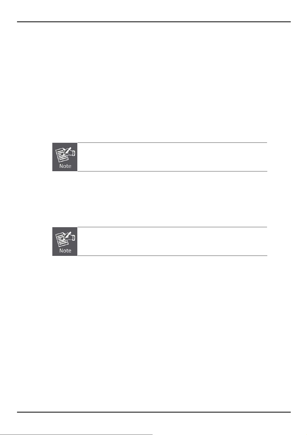
Step2: Attach the rack-mount bracket to each side of the Managed Switch with supplied screws attached to the
package.
Figure 2-5 shows how to attach brackets to one side of the Managed Switch.
14
Page 15
FGSW-2620VM / FGSW-2624SF User’s Manual
Figure 2-5 Attach brackets to the Managed Switch.
You must use the screws supplied with the mounting brackets. Damage caused to the parts
by using incorrect screws would invalidate the warranty.
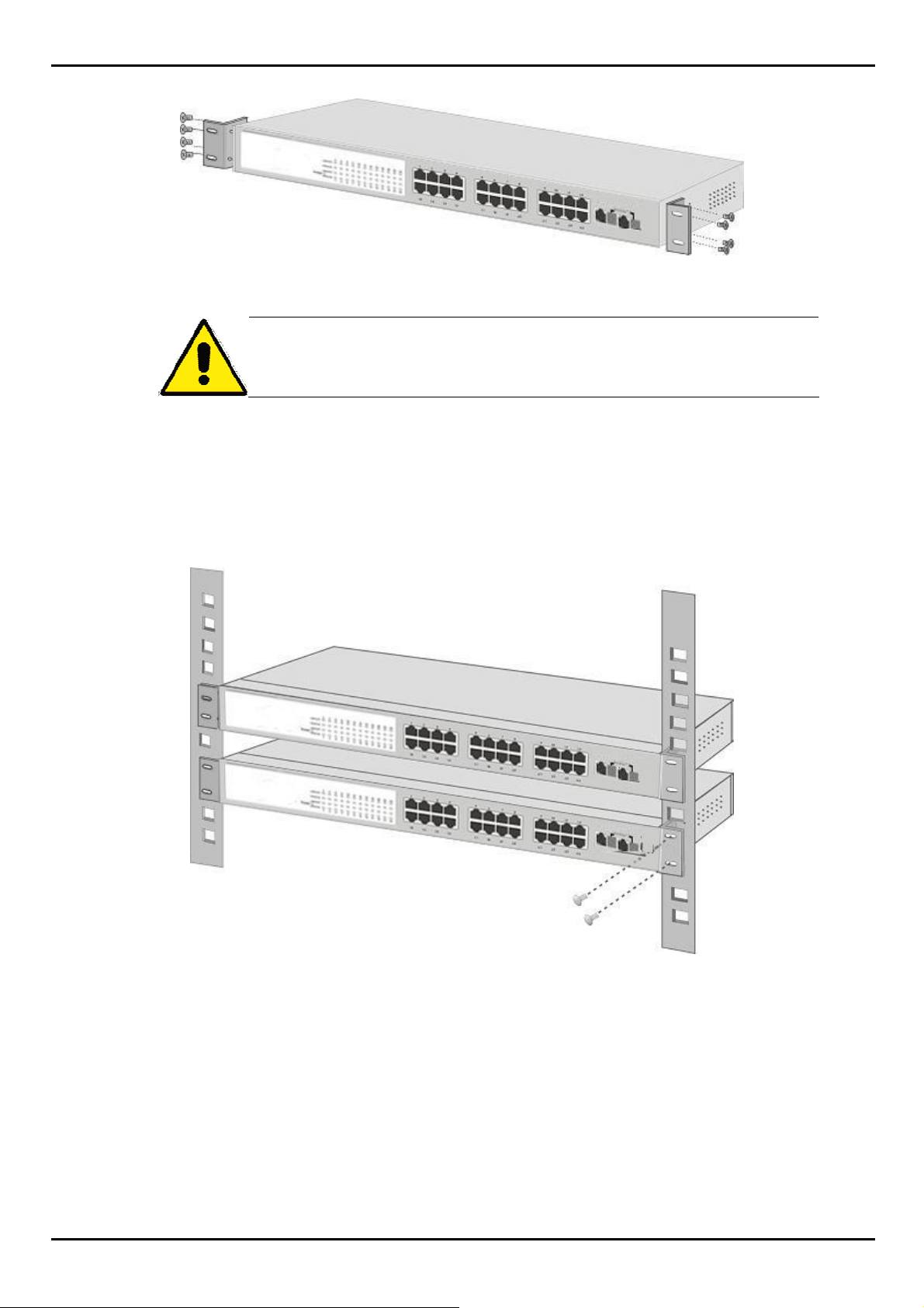
Step3: Secure the brackets tightly.
Step4: Follow the same steps to attach the second bracket to the opposite side.
Step5: After the brackets are att ached to the Managed Switch, use suitable screws to securely attach the bracket s to the
rack, as shown in Figure 2-6.
Figure 2-6 Mounting the Switch in a Rack
Step6: Proceeds with the steps 4 and steps 5 of session 2.2.1 Desktop Installation to connect the network cabling and
supply power to the Managed Switch.
15
Page 16

FGSW-2620VM / FGSW-2624SF User’s Manual
2.2.3 Installing the SFP transceiver
The sections describe how to insert an SFP transceiver into an SFP slot.
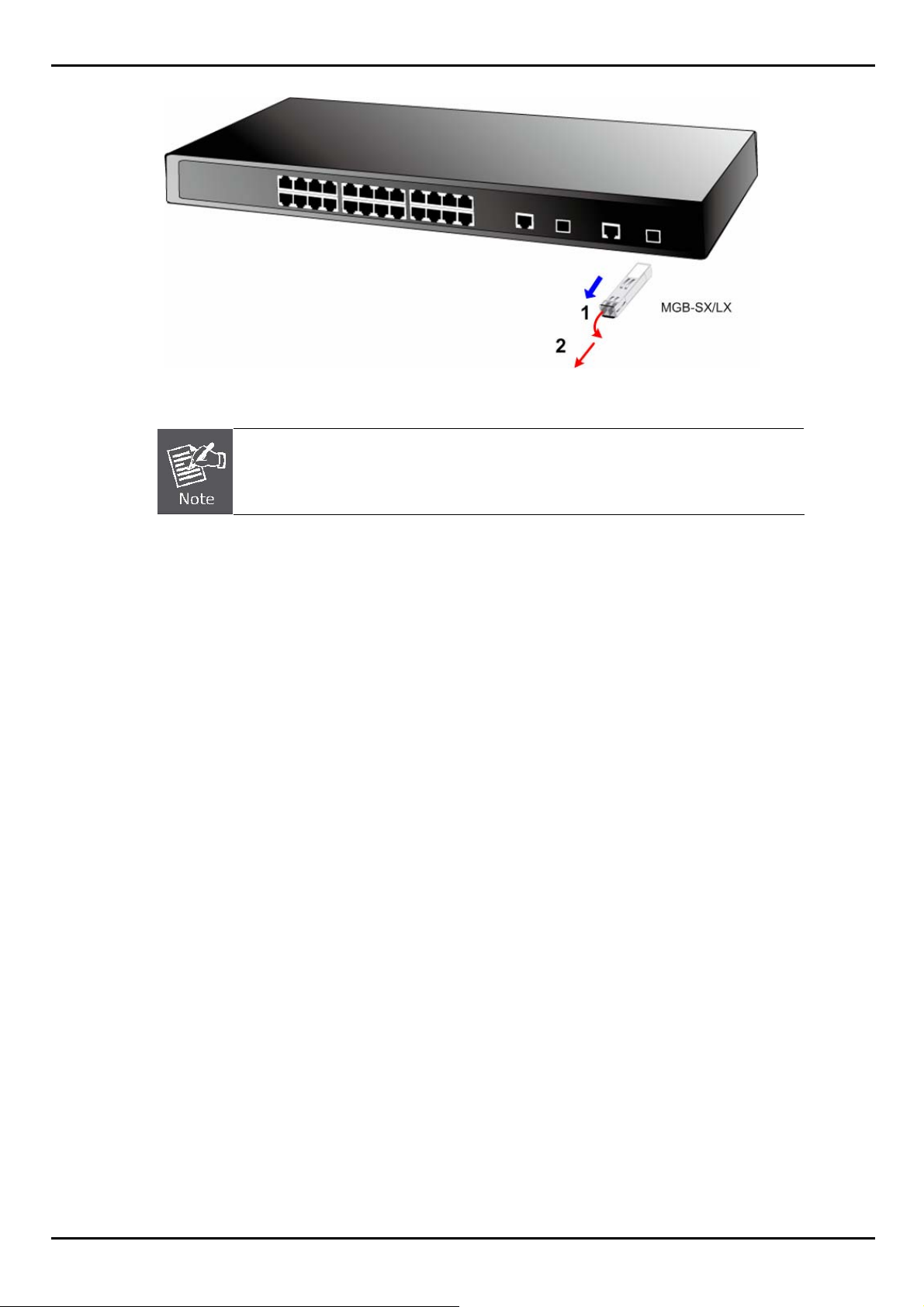
The SFP transceivers are hot-pluggable and hot-swappable. You can plug-in and out the transceiver to/from any SFP
port without having to power down the Managed Switch. As the Figure 2-7 appears.
Figure 2-7 Plug-in the SFP transceiver
Approved PLANET SFP Transceivers
PLANET Managed Switches supports both single mode and multi mode SFP transceiver. The following list of approved
PLANET SFP transceivers is correct at the time of publication:
100Base-FX SFP transceiver (FGSW-2624SF / 100Base-FX SFP Slot only):
■MFB-FX SFP (100Base-FX SFP transceiver – Multi mode / 2km / TX 1300nm)
■MFB-F20 SFP (100Base-FX SFP transceiver – Single Mode / 20km / RX 1310nm)
■MFB-FA20- SFP (100Base-FX SFP transceiver – Single Mode / WDM / 20Km / TX 1310nm)
■MFB-FB20 SFP (100Base-FX SFP transceiver –Single Mode / WDM / 20Km / TX: 1550nm)
1000Base-SX/LX SFP transceiver:
■MGB-SX SFP (1000Base-SX SFP transceiver – Multi mode / 220m)
■MGB-LX SFP (1000Base-LX SFP transceiver - Single Mode / 10km)
■MGB-L30 SFP (1000Base-LX SFP transceiver – Single Mode / 30Km)
■MGB-L50 SFP (1000Base-LX SFP transceiver - Single Mode / 50Km)
16
Page 17

FGSW-2620VM / FGSW-2624SF User’s Manual
It recommends using PLANET SFPs on the Managed Switch. If you insert a SFP transceiver
that is not supported, the Managed Switch will not recognize it.
Before connect the other switches, workstation or Media Converter.
1. Make sure both side of the SFP transceiver are with the same media type, for example: 1000Base-SX to
1000Base-SX, 1000Bas-LX to 1000Base-LX.
2. Check the fiber-optic cable type match the SFP transceiver model.
¾ To connect to 1000Base-SX SFP transceiver, use the multi-mode fiber cable- with one side must be male
duplex LC connector type.
¾ To connect to 1000Base-LX SFP transceiver, use the single-mode fiber cable-with one side must be male
duplex LC connector type.
Connect the fiber cable
1. Attach the duplex LC connector on the network cable into the SFP transceiver.
2. Connect the other end of the cable to a device – switches with SFP installed, fiber NIC on a workstation or a Media
Converter..
3. Check the LNK/ACT LED of the SFP slot on the front of the Switch. Ensure that the SFP transceiver is operating
correctly.
4. Check the Link mode of the SFP port if the link failed. Co works with some fiber-NICs or Media Converters, set the
Link mode to “1000 Force” is needed.
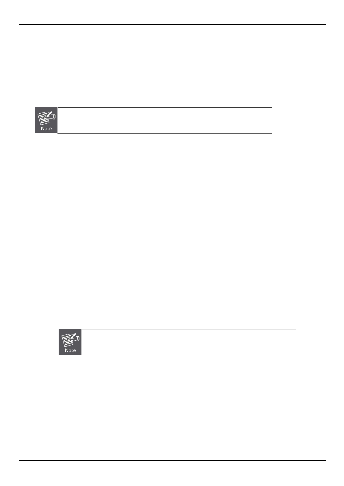
Remove the transceiver module
1. Make sure there is no network activity by consult or check with the network administrator. Or through the
management interface of the switch/converter (if available) to disable the port in advance.
2. Remove the Fiber Optic Cable gently.
3. Turn the handle of the MGB module to horizontal.
4. Pull o ut the module gently through the handle.
17
Page 18
FGSW-2620VM / FGSW-2624SF User’s Manual
Figure 2-8 Pull out the SFP transceiver
Never pull out the module without pull the handle or the push bolts on the module. Direct pull
out the module with violent could damage the module and SFP module slot of the Managed
Switch.
18
Page 19
FGSW-2620VM / FGSW-2624SF User’s Manual
3. SWITCH MANAGEMENT
This section introduces the configuration and functions of the Web-Based management. The following configuration
descriptions are based on the kernel software version 1.07.
The following section will base on the Web screens of FGSW-2620VM, for FGSW-2624SF
the display will be the same to FGSW-2620VM.
3.1 About Web-based Management
Inside the CPU board of the Managed Switch exist an embedded HTML web site residing in flash memory. It offers
advanced management features and allow users to manage the Managed Switch from anywhere on the network
through a standard browser such as Microsoft Internet Explorer.
The Web-Based Management supports Internet Explorer 6.0. It is based on Java Applets with an aim to reduce network
bandwidth consumption, enhance access speed and present an easy viewing screen.
3.2 Requirements
Workstations of subscribers running Windows 98/ME, NT4.0, 2000/XP, MAC OS9 or later, Linux, UNIX or
other platform compatible with TCP/IP protocols.
Workstation installed with Ethernet NIC (Network Interface Card)
Ethernet Port connect
• Network cables - Use standard network (UTP) cables with RJ45 connectors.
Above Workstation installed with WEB Browser and JAVA runtime environment Plug-in
By default, IE6.0 or later version does not allow Java Applets to open sockets. The user has
to explicitly modify the browser setting to enable Java Applets to use network ports.
19
Page 20
FGSW-2620VM / FGSW-2624SF User’s Manual
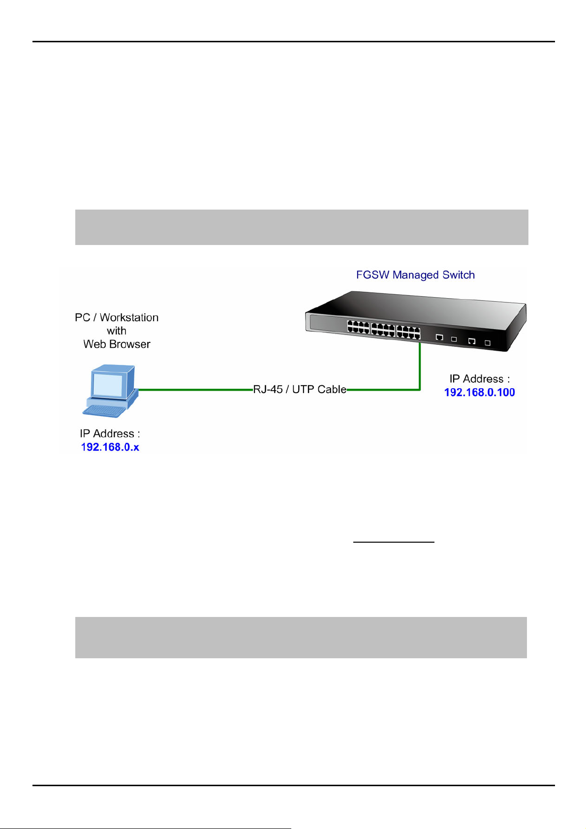
3.3 Preparing for Web Management
The following shows how to start up the Web Management of the Managed Switch. Note the FGSW Managed Switch is
configured through an Ethernet connection, please make sure the manager PC must be set on the same IP subnet
address.
For example, the default IP address of the FGSW Managed Switch is 192.168.0.100, then the manager PC should b e
set at 192.168.0.x (where x is a number between 1 and 254, except 100), and the default subnet mask is
255.255.255.0.
IP Address: 192.168.0.100
Subnet Mask: 255.255.255.0
Figure 3-1 IP Management diagram
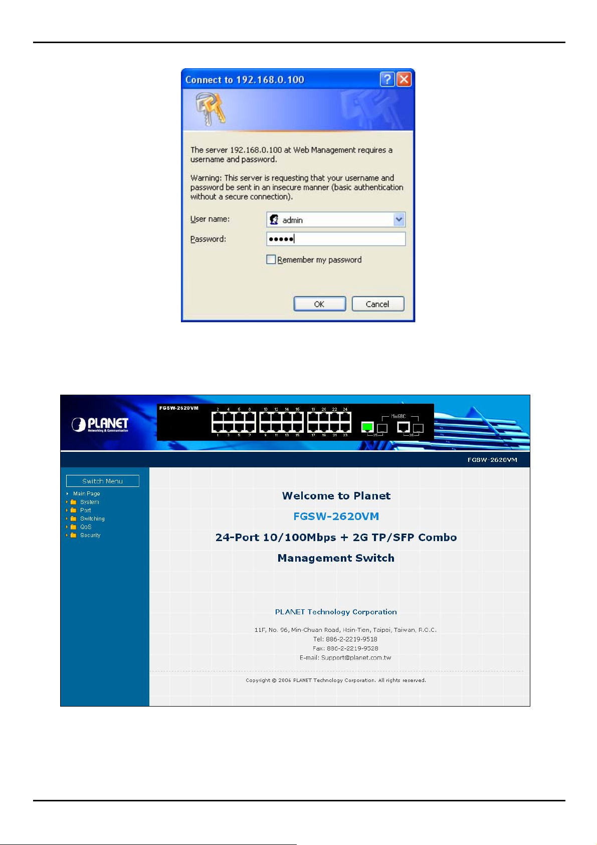
3.4 System Login
1. Use Internet Explorer 6.0 or above Web browser, enter IP address http://192.168.0.100 (the factory-default IP
address or that you have just changed in console) to access the Web interface.
2. When the following dialog box appears, please enter the default user name "admin" and password “admin” (or the
username/password you have changed via console). The login screen in Figure 3-2 appear s.
Default User name: admin
Default Password: admin
20
Page 21
FGSW-2620VM / FGSW-2624SF User’s Manual
Figure 3-2 Login screen
3. Click "Enter" or "OK", then the home screen of the Web-based management appears.
Figure 3-3 FGSW-2620VM Web Management Interface
21
Page 22
FGSW-2620VM / FGSW-2624SF User’s Manual
3.5 Online Help
You can click button when you have any configuration q uestion during the configuring.
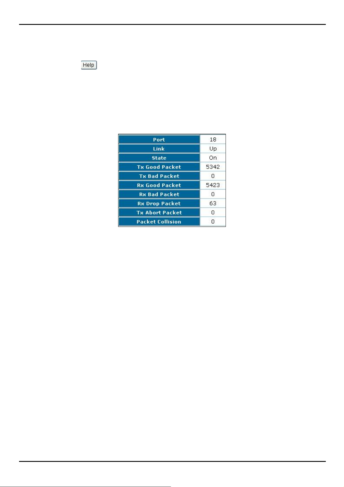
3.6 View the Port Information
You can direct click the port on the Switch figure on the top of web page. Then, you will see the port information.
Figure 3-4
Port information interface
22
Page 23
FGSW-2620VM / FGSW-2624SF User’s Manual
4. WEB-BASED MANAGEMENT
To modify your PC’s IP domain to the same with Managed Switch then use the default IP address (192.168.0.100) to
remote configure Managed Switch through the Web interface.
#Notice:
The following section will base on the Web screens of FGSW-2620VM, for FGSW-2624SF the display will be the same
to FGSW-2620VM.
4.1 System
In System, it has seven parts of setting
System information
IP Configuration
Account Password
SNMP Management
TFTP Upgrade
Factory Default
System Reboot.
We will describe the configure detail in following.
4.1.1 System Information
In System information, it has two parts of setting – basic and advanced. We will describe the configure detail in following.
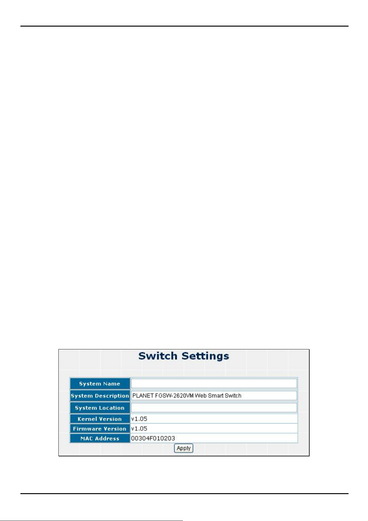
4.1.1.1 Basic
In Basic switch setting, it displays the Switch basic information.
Figure 4-1-1 Switch setting screenshot
23
Page 24
Object Description
FGSW-2620VM / FGSW-2624SF User’s Manual
System Name
System Description
System Location
Kernel Version
Firmware Version
MAC A ddre ss
Apply button
The name of Switch.
The description of Switch.
The Switch physical location.
The kernel software version.
The Switch's firmware version.
The unique hardware address assigned by manufacturer (de fault).
Press the button to complete the configuration.
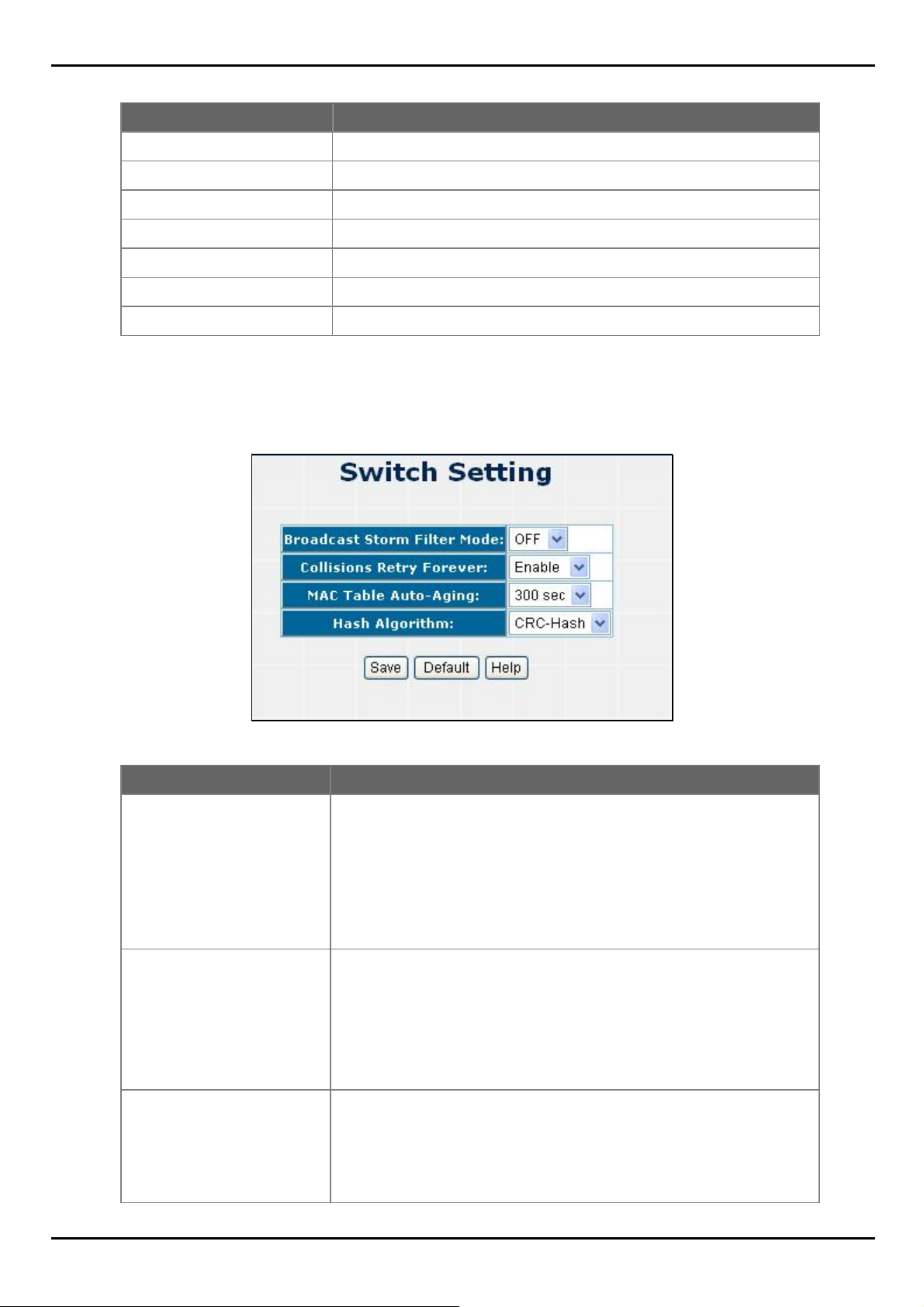
4.1.1.2 Advanced
Choose Advanced from System Information of Managed Switch, the screen in Figure 4-1-2 appears.
Figure 4-1-2 Switch Advanced setting screenshot
Object Description
Broadcast Storm Filter Mode
Collision Retry Forever Provide Collision Retry Forever function ”Disable” or ”Enable” on Switch; If
MAC Table Auto-Aging
Configure broadcast storm control. Enable it and set the upper threshold for
individual ports. The threshold is the percentage of the port's total bandwidth
used by broadcast traffic. When broadcast traffic for a port rises above the
threshold you set, broadcast storm control becomes active. The valid
threshold values are 1/2, 1/4, 1/8, 1/16 and off. Default is “1/4”.
this function is disabled, when a packet meet a collision, the Switch will retry 6
times before discard the packets. Otherwise, the Switch will retry until the
packet is successfully sent.
Default mode is Enable.
Fill in the number of seconds that an inactive MAC address remains in the
Switch's address table. The valid threshold values are 150, 300, 600 seconds
and off.
Default is “300” seconds.
24
Page 25
FGSW-2620VM / FGSW-2624SF User’s Manual
Hash Algorithm Provide MAC address table Hashing setting on Switch; available options are
CRC Hash and Direct Map.
Default mode is CRC-Hash.
Save button
Press the button to complete the configuration.
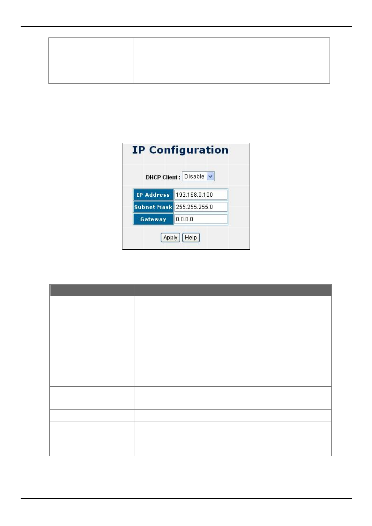
4.1.2 IP Configuration
User can configure the IP Settings and DHCP client function, the screen in Figure 4-1-3 appears.
Object Description
DHCP Client
IP Address
Subnet Mask
Gateway
Figure 4-1-3 IP configuration screenshot
"Enable" is to get IP from DHCP server. "Disable" is opposite. The DHCP
client function only works if you haven't assigned a static IP address that
different than the switch default IP. Once the default IP has been changed
the DHCP will not effective and the switch will continue using the manually
entered static IP. If you have changed the switch to a static IP address, you
can set the IP address back to its default IP address or you can reset the
Switch back to factory default. And then you can enable the DHCP client
function to work.
Assign the Switch IP address.
The default IP is 192.168.0.100.
Assign the Switch IP subnet mask.
Assign the Switch gateway.
The default value is 0.0.0.0.
Apply button
Press the button to complete the configuration.
25
Page 26
FGSW-2620VM / FGSW-2624SF User’s Manual
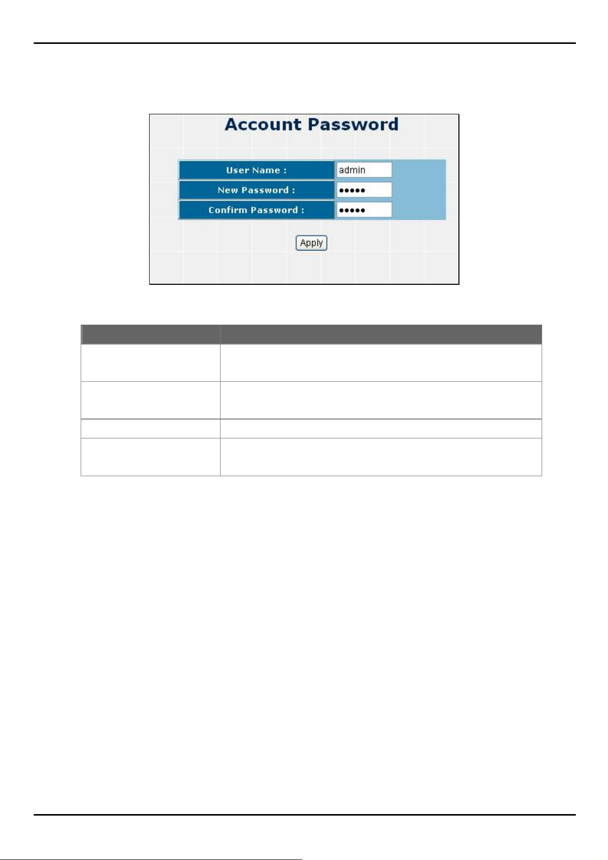
4.1.3 Account Password
You can change web management login user name and password.
Figure 4-1-4 Account password screenshot
Object Description
User name
New Password
Confirm password
Apply button
Type the new user name.
The default is "admin".
Type the new password.
The default is "admin".
Retype the new password.
Press the button for save current User name and Password Setting on the
Switch.
26
Page 27

FGSW-2620VM / FGSW-2624SF User’s Manual
4.1.4 SNMP Management
The SNMP is a Protocol that governs the transceiver of information between management and agent. The Switch
supports SNMP V1.
You can define management stations as trap managers and to enter SNMP community strings. You also can define a
name, location, and contact person for the Switch. Fill in the system options data, and then click Apply to update the
changes.
4.1.4.1 System Configuration
Community strings: serve as password
Figure 4-1-5 SNMP-System Configuration screenshot
Object Description
Strings
RO
RW
Add button
Remove button
Fill the name of string.
Read only. Enables requests accompanied by this string to display
MIB-object information.
Read write. Enables requests accompanied by this string to display
MIB-object information and to set MIB objects.
Press the button to add the management SNMP community strings
on the Switch.
Press the button to remove the management SNMP community
strings on the Switch.
27
Page 28
FGSW-2620VM / FGSW-2624SF User’s Manual
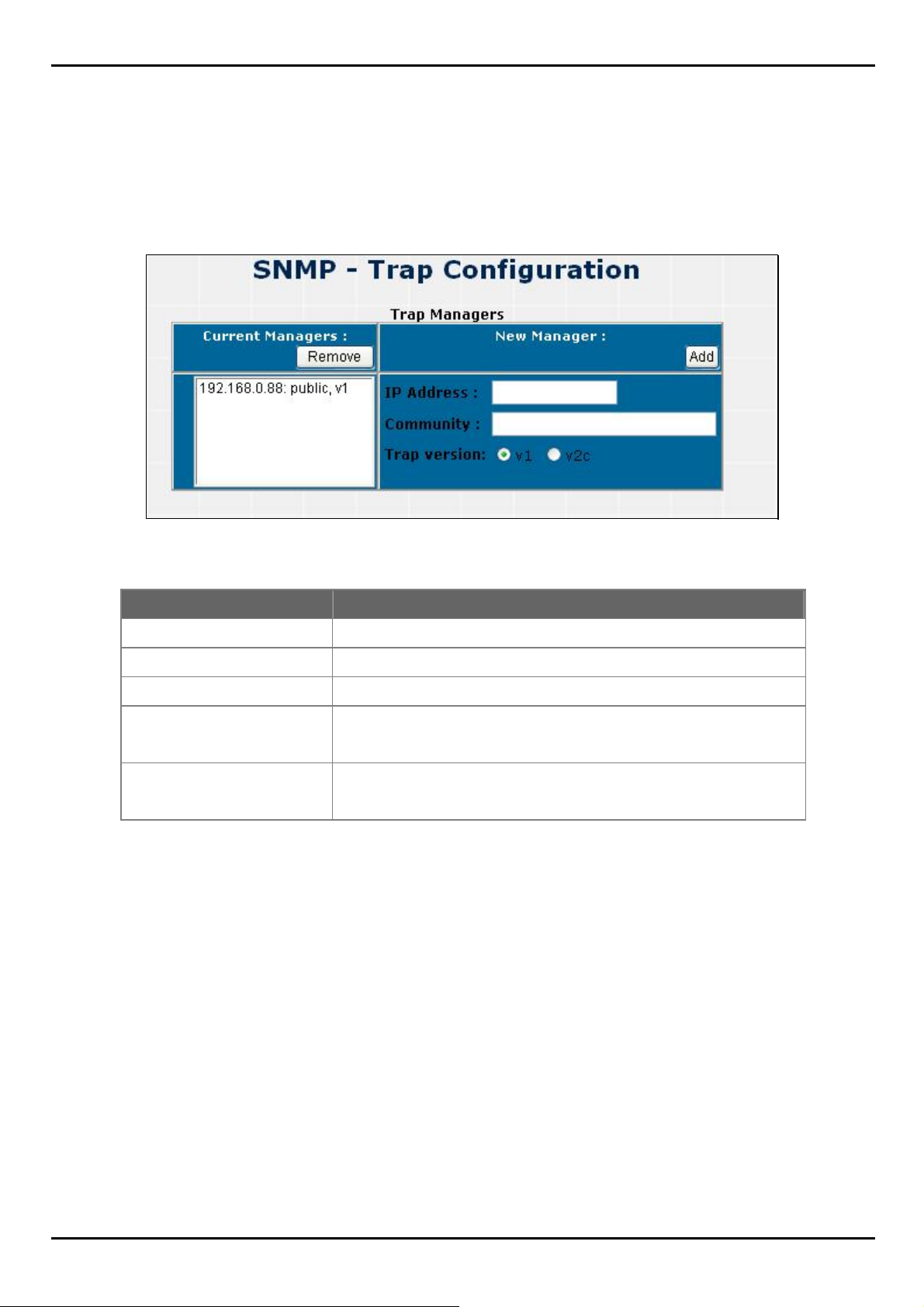
4.1.4.2 Trap Configuration
Trap Manager
A trap manager is a management station that receives traps, the system alerts generated by the switch. If no trap
manager is defined, no traps will issue. Create a trap manager by entering the IP address of the station and a community
string.
Figure 4-1-6 Trap Management screenshot
Object Description
IP Address
Community Strings
Trap version
Add button
Remove button
Fill in the trap device IP.
The trap device community strings.
The Trap version.
Press the button to add the management SNMP community strings on the
Switch.
Press the button to remove the management SNMP community strings on
the Switch.
28
Page 29
FGSW-2620VM / FGSW-2624SF User’s Manual
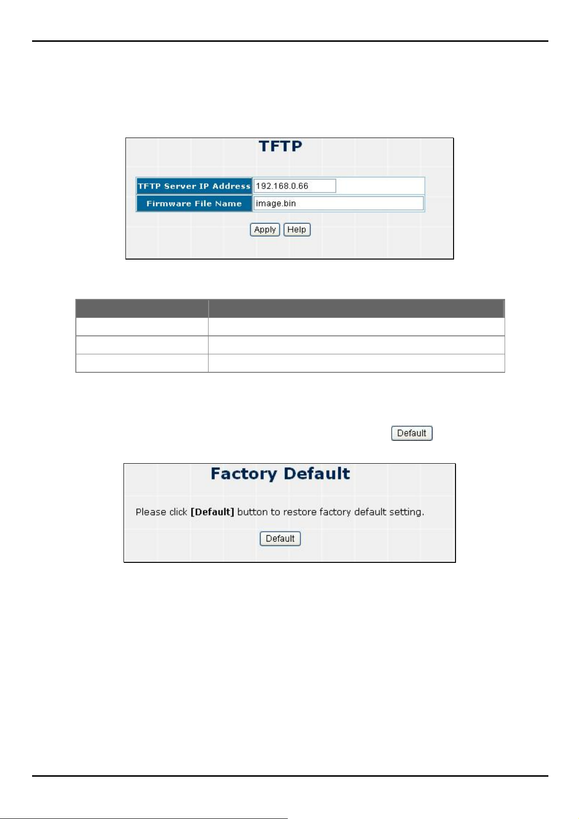
4.1.5 TFTP Upgrade
It provides the functions to allow a user to update the Switch firmware. Before updating, make sure you have your TFTP
server ready and the firmware image is on the TFTP server.
Figure 4-1-7 TFTP Update Firmware screentshot
Object Description
TFTP Server IP Address
Firmware File Name
Apply button
Fill in your TFTP server IP.
The name of firmware image.
Press the button for upgrade the Switch firmware.
4.1.6 Factory Default
Reset Switch to default configuration, default value to as following configuration: Click button to reset Switch
to default setting.
Figure 4-1-8 Factory Default screenshot
After the “Default” buttomn be pressed and reboot, the system will load the default IP settings as following:
。 Default IP address: 192.168.0.100
。 Subnet mask: 255.255.255.0
。 Default Gateway: 0.0.0.0
。 The other setting value is back to disable or none.
29
Page 30

FGSW-2620VM / FGSW-2624SF User’s Manual
4.1.7 System Reboot
Reboot the Switch in software reset. Click button to reboot the Switch.
Figure 4-1-9 System Reboot screenshot
30
Page 31

FGSW-2620VM / FGSW-2624SF User’s Manual
4.2 Port Configuration
In Port page, it has five parts of setting
Port control
Port mirror
Bandwidth control
Port statistics
Port trunk.
We will describe the configure detail in following.
4.2.1 Port Control
This section introduces detail settings of per port on Switch; the screen in Figure 4-2-1 appears and following table
descriptions the Port Configuration objects of the Switch.
Figure 4-2-1 Port Control screenshot
Object Description
Port
State
Auto Negotiation
Speed/Duplex
Flows Control
Apply button
When you select the port, you can see port current configure shows in below.
Select the port by scroll the list in Port column.
User can disable or enable this port control.
User can set auto negotiation mode is Auto, N-way (specify the speed/duplex on
this port and enable auto-negotiation), Force of the port.
Set the speed and full-duplex or half-duplex mode of the port.
Set flow control function is ON or OFF in Full Duplex mode.
Press the button to apply all configurations.
31
Page 32

FGSW-2620VM / FGSW-2624SF User’s Manual
Figure 4-2-2 Select the Port Control screenshot
For the model FGSw-2624SF, Port-1 to Port-24 is set to 100Full as default setting.
32
Page 33

FGSW-2620VM / FGSW-2624SF User’s Manual
4.2.2 Port Mirror
The Port mirroring is a method for monitor traffic in switched networks. Traffic through ports can be monitored by one
specific port. That is, traffic goes in or out monitored ports will be duplicated into mirror port.
Figure 4-2-3 Prot Mirroring screenshot
Object Description
Port Mirroring Mode
Analysis Port
Monitor Port
Apply button
If you want to disable the function, you must select monitor port to none.
Set mirror mode:
Its mean mirror port can be used to see all monitor port traffic. You can connect
mirror port to LAN analyzer or netxray.
The ports you want to monitor. All monitor port traffic will be copied to mirror port.
You can select max 25 monitor ports in the switch. User can choose which port
wants to monitor in only one mirror mode.
Press the button to apply all configurations.
Disable,
RX,
TX,
Both.
33
Page 34

FGSW-2620VM / FGSW-2624SF User’s Manual
4.2.3 Bandwidth Control
This section provides current rate limit and traffic shapping status of each port from the Switch, the screen in Figure
4-2-4 appears.
Object Description
InRate*
OutRate*
Save button
Input the value of packet rate sent from the connected port to this port must enable
the flow control feature of this port for the function to work normally.
The available value ranges from 1 to 99 and rate unit: 1Mbps.
Input the value of packet rate sent from this port to the connected port.
The available value ranges from 1 to 99 and rate unit: 1Mbps.
Press the button to save all configurations.
Figure 4-2-4 Bandwidth Control Screenshot
34
Page 35

FGSW-2620VM / FGSW-2624SF User’s Manual
4.2.4 Port Statistics
The following information provides a view of the current port statistic information. Scroll down for more ports statistics.
Figure 4-2-5 Port Statistics screenshot
Object Description
Port
Type Display the Speed duplex mode of each port on the Switch.
Link The state of the link, indicating a valid link partner device. "Up" means a device is successful
State Display the port Disable or Enable state of each port on the Switch.
Clear button
Indicate port 1 to port 26.
connected to the port. “Down” means no device is connected.
Press the button to clean all counts.
35
Page 36

FGSW-2620VM / FGSW-2624SF User’s Manual
4.2.5 Port Trunk
The Link Aggregation Control Protocol (LACP) provides a standardized means for exchanging information between
Partner Systems on a link to allow their Link Aggregation Control instances to reach agreement on the identity of the
Link Aggregation Group to which the link belongs, move the link to that Link Aggregation Group, and enable its
transmission and reception functions in an orderly manner. Link aggregation lets you group up to eight consecutive ports
into a single dedicated connection. This feature can expand bandwidth to a device o n the network. LACP operation
requires full-duplex mode, more detail information refers to IEEE 802.3ad.
4.2.5.1 Aggregator setting
This section provides Port Trunk-Aggregator Setting of each port from the Switch, the screen in Figure 4-2-6 appears.
Object Description
System Priority
Group ID
Select button
Lacp
A value used to identify the active LACP. The switch with the lowest value has the highest
priority and is selected as the active LACP.
There are seven trunk groups to provide configure.
Press the button to Choose the "Group ID".
If enable, the group is LACP static trunk group. If disable, the group is local static trunk
group. All ports support LACP dynamic trunking group. If connecting to the device that
also supports LACP, the LACP dynamic trunking group will be created automatically.
If LACP enable, you can configure LACP Active/Passive status in each ports on State
Activity page.
Figure 4-2-6 Aggregator setting interface
36
Page 37

FGSW-2620VM / FGSW-2624SF User’s Manual
Work Ports
Choose Port
Add button
Remove button
Apply button
Delete button
Allow max four ports can be aggregated at the same time. If LACP static trunk group, the
exceed ports are standby and able to aggregate if work ports fail. If it is local static trunk
group, the number must be as same as the group member ports.
Select the ports to join the trunk group. Allow max four ports can be aggregated at the
same time.
Press the button to add the port.
Press the button to remove unwanted ports.
Press the button to save the configuerations.
Press the button to delete Trunk Group and the Group ID.
4.2.5.2 Aggregator Information
When you had setup the LACP aggregator, you will see relation information in here.
Figure 4-2-7 Trunking - Aggregator Information interface
Object Description
Group Key
Port Member
Indicates the Static Trunking Groupd ID.
Indicates the selected ports that joined the Trunk group.
37
Page 38

FGSW-2620VM / FGSW-2624SF User’s Manual
4.2.5.3 Aggregator State Activity
When you had setup the LACP aggregator, you can configure port state activity. You can mark or un-mark the port.
Object Description
Active
Passive
Apply button
1. A link having either two active LACP ports or one active port can perform dynamic
2. A link has two passive LACP ports will not perform dynamic LACP trunking because
3. If you are active LACP's actor, when you are select trunking port, the active status will
The port automatically sends LACP protocol packets.
The port does not automatically send LACP protocol packets, and responds only if
it receives LACP protocol packets from the opposite device.
Press the button to change the port state activity. Opposite is Passive.
LACP trunking.
both ports are waiting for and LACP protocol packet from the opposite device.
be created automatically.
Figure 4-2-8
Trunking – State Activity interface
38
Page 39

FGSW-2620VM / FGSW-2624SF User’s Manual
4.3 Switching
In Switch page, it has four parts of setting
VLAN,
Rapid Spanning Tree
IGMP snooping
Forwarding table.
We will describe the configure detail in following.
4.3.1 VLAN
Understanding IEEE 802.1p Priority
Priority tagging is a function defined by the IEEE 802.1p standard designed to provide a means of managing traffic on a
network where many different types of data may be transmitted simultaneously. It is intended to alleviate problems
associated with the delivery of time critical data over congested networks. The quality of applications that are dependent
on such time critical data, such as video conferencing, can be severely and adversely affected by even very small delays
in transmission.
Network devices that are in compliance with the IEEE 802.1p standard have the ability to recognize the priority level of
data packets. These devices can also assign a priority label or tag to packets. Compliant devices can also strip priority
tags from packets. This priority tag determines the packet's degree of expeditiousness and determines the queue to
which it will be assigned.
Priority tags are given values from 0 to 7 with 0 being assigned to the lowest priority data and 7 assigned to the highest.
The highest priority tag 7 is generally only used for data associated with video or audio applications, which are sens itive
to even slight delays, or for data from specified end users whose data transmissions warrant special consideration.
The Switch allows you to further tailor how priority tagged data packets are handled on your network. Using queues to
manage priority tagged data allows you to specify its relative priority to suit the needs of your network. There may be
circumstances where it would be advantageous to group two or more differently tagged packets into the same queue.
Generally, however, it is recommended that the highest priority queue, Queue 1, be reserved for data packets with a
priority value of 7. Packets that have not been given any priority value are placed in Queue 0 and thus gi ven the lowest
priority for delivery.
A weighted round robin system is employed on the Switch to determine the rate at which the queues are emptied of
packets. The ratio used for clearing the queues is 4:1. This means that the highest priority queue, Queue 1, will clear 4
packets for every 1 packet cleared from Queue 0.
Remember, the priority queue settings on the Switch are for all ports, and all devices connected to the Switch will be
affected. This priority queuing system will be especially beneficial if your network employs switches with the capability of
assigning priority tags.
39
Page 40

FGSW-2620VM / FGSW-2624SF User’s Manual
VLAN Description
A Virtual Local Area Network (VLAN) is a network topology configured according to a logical scheme rather than the
physical layout. VLAN can be used to combine any collection of LAN segments into an autonomous user group that
appears as a single LAN. VLAN also logically segment the network into different broadcast domains so that packets are
forwarded only between ports within the VLAN. Typically, a VLAN corresponds to a particular subnet, although not
necessarily.
VLAN can enhance performance by conserving bandwidth, and improve security by limiting traffic to specific domains.
A VLAN is a collection of end nodes grouped by logic instead of physical location. End nodes that frequently
communicate with each other are assigned to the same VLAN, regardless of where they are physically on the network.
Logically, a VLAN can be equated to a broadcast domain, because broadcast packets are forwarded to only members of
the VLAN on which the broadcast was initiated.
Port-based VLAN
Port-based VLAN limit traffic that flows into and out of switch ports. Thus, all devices connected to a port are members of
the VLAN(s) the port belongs to, whether there is a single computer directly connected to a switch, or an entire
department.
On port-based VLAN.NIC do not need to be able to identify 802.1Q tags in packet headers. NIC send and receive
normal Ethernet packets. If the packet's destination lies on the same segment, communications take place using normal
Ethernet protocols. Even though this is always the case, when the destination for a packet lies on another switch port,
VLAN considerations come into play to decide if the packet is dropped by the Switch or delivered.
IEEE 802.1Q VLANs
IEEE 802.1Q (tagged) VLAN are implemented on the Switch. 802.1Q VLAN require tagging, which enables them to
span the entire network (assuming all switches on the network are IEEE 802.1Q-compliant).
VLAN allow a network to be segmented in order to reduce the size of broadcast domains. All packets entering a VLAN
will only be forwarded to the stations (over IEEE 802.1Q enabled switches) that are members of that VLAN, and this
includes broadcast, multicast and unicast packets from unknown sources.
VLAN can also provide a level of security to your network. IEEE 802.1Q VLAN will only deliver packets between stations
that are members of the VLAN. Any port can be configured as either tagging or untagging. The untagging feature of
IEEE 802.1Q VLAN allows VLAN to work with legacy switches that don't recognize VLAN tags in packet headers. The
tagging feature allows VLAN to span multiple 802.1Q-compliant switches through a single physical connection and
allows Spanning Tree to be enabled on all ports and work normally.
Any port can be configured as either tagging or untagging. The untagging feature of IEEE 802.1Q VLAN allow VLAN to
work with legacy switches that don’t recognize VLAN tags in packet headers. The tagging feature allows VLAN to span
multiple 802.1Q-compliant switches through a single physical connection and allows Spanning Tree to be enabled on all
ports and work normally.
40
Page 41

FGSW-2620VM / FGSW-2624SF User’s Manual
Some relevant terms:
Tagging - The act of putting 802.1Q VLAN information into the header of a packet.
Untagging - The act of stripping 802.1Q VLAN information out of the packet header.
802.1Q VLAN Tags
The figure below shows the 802.1Q VLAN tag. There are four additional octets inserted after the source MAC address.
Their presence is indicated by a value of 0x8100 in the Ether Type field. When a packet's Ether Type field is equal to
0x8100, the packet carries the IEEE 802.1Q/802.1p tag. The tag is contained in the following two octets and consists of
3 bits of user priority, 1 bit of Canonical Format Identifier (CFI - used for encapsulating Token Ring packets so they can
be carried across Ethernet backbones), and 12 bits of VLAN ID (VID). The 3 bits of user priority are used by 802.1p. The
VID is the VLAN identifier and is used by the 802.1Q standard. Because the VID is 12 bits long, 4094 unique VLAN can
be identified.
The tag is inserted into the packet header making the entire packet longer by 4 octets. All of the information originally
contained in the packet is retained.
802.1Q Tag
User Priority CFI VLAN ID (VID)
3 bits 1 bits 12 bits
TPID (Tag Protocol Identifier) TCI (Tag Control Information)
2 bytes 2 bytes
Preamble Destination
Address
Source
Address
VLAN TAG Ethernet
Type
Data FCS
6 bytes 6 bytes 4 bytes 2 bytes 46-1517 bytes 4 bytes
The Ether Type and VLAN ID are inserted after the MAC source address, but before the original Ether Type/Length or
Logical Link Control. Because the packet is now a bit longer than it was originally, the Cyclic Redundancy Check (CRC)
must be recalculated.
Adding an IEEE802.1Q Tag
Dest. Addr. Src. Addr. Length/E. type Data Old CRC
Original Ethernet
Dest. Addr. Src. Addr. E. type Tag Length/E. type Data New CRC
Priority CFI VLAN ID
New Tagged Packet
Port VLAN ID
Packets that are tagged (are carrying the 802.1Q VID information) can be transmitted from one 802.1Q compliant
network device to another with the VLAN information intact. This allows 802.1Q VLAN to span network devices (and
indeed, the entire network – if all network devices are 802.1Q compliant).
41
Page 42

FGSW-2620VM / FGSW-2624SF User’s Manual
Every physical port on a switch has a PVID. 802.1Q ports are also assigned a PVID, for use within the switch. If no
VLAN are defined on the switch, all ports are then assigned to a default VLAN with a PVID equal to 1. Untagged packets
are assigned the PVID of the port on which they were received. Forwarding decisions are based upon this PVID, in so
far as VLAN are concerned. Tagged packets are forwarded according to the VID contained within the tag. Tagged
packets are also assigned a PVID, but the PVID is not used to make packet forwarding decisions, the VID is.
Tag-aware switches must keep a table to relate PVID within the switch to VID on the network. The switch will compare
the VID of a packet to be transmitted to the VID of the port that is to transmit the packet. If the two VID are different the
switch will drop the packet. Because of the existence of the PVID for untagged packets and the VID for tagged packets,
tag-aware and tag-unaware network devices can coexist on the same network.
A switch port can have only one PVID, but can have as many VID as the switch has memory in its VLAN table to store
them.
Because some devices on a network may be tag-unaware, a decision must be made at each port on a tag-aware device
before packets are transmitted – should the packet to be transmitted have a tag or not? If the transmitting port is
connected to a tag-unaware device, the packet should be untagged. If the transmitting port is connected to a tag-aware
device, the packet should be tagged.
Default VLANs
The Switch initially configures one VLAN, VID = 1, called "default." The factory default setting assigns all ports on the
Switch to the "default". As new VLAN are configured in Port-based mode, their respective member ports are removed
from the "default."
VLAN and Link aggregation Groups
In order to use VLAN segmentation in conjunction with port link aggregation groups, you can first set the port link
aggregation group(s), and then you may configure VLAN settings. If you wish to change the port link aggregation
grouping with VLAN already in place, you will not need to reconfigure the VLAN settings after changing the port link
aggregation group settings. VLAN settings will automatically change in conjunction with the change of the port link
aggregation group settings
4.3.1.1 VLAN configuration
A Virtual LAN (VLAN) is a logical network grouping that limits the broadcast domain. It allows you to isolate network
traffic so only members of the VLAN receive traffic from the same VLAN members. Basically, creating a VLAN from a
switch is logically equivalent of reconnecting a group of network devices to another La yer 2 switch. However, all the
network devices are still plug into the same switch physically.
The switch supports port-based, 802.1Q (tagged-based) and protocol-base VLAN in web managem ent page. In the
default configuration, VLAN support is “disable”.
42
Page 43

FGSW-2620VM / FGSW-2624SF User’s Manual
4.3.1.1.1 Port-based VLAN
Packets can go among only members of the same VLAN group. Note all unselected ports are treated as belonging to
another single VLAN. If the port-based VLAN enabled, the VLAN-tagging is ignored.
In order for an end station to send packets to different VLANs, it itself has to be either capable of tagging packets it
sends with VLAN tags or attached to a VLAN-aware bridge that is capable of classifying and tagging the packet with
different VLAN ID based on not only default PVID but also other information about the packet, such as the protocol.
1. Click the h yperlink "VLAN Configuration" to enter the VLAN configuration interface.
2. Select “PortBased” at the VLAN Operation Mode, to enable the port-based VLAN function.
Figure 4-3-1 VLAN – PortBase interface
Object Description
Group ID
Port
VLAN Type
3. Click
4. Enter the VLAN Group ID, the available range is 2-4094.
5. Select the me mbers for the VLAN group.
6. Click
7. You will see the VLAN Group displays.
You can configure the ID number of the VLAN by this item. This field is used to add VLANs one at a
time. The VLAN group ID and available range is 2-4094
Indicate port 1 to port 26.
---------Member
to create a new VLAN group. Then the following figure appears.
button.
Forbidden ports are not included in the VLAN
Defines the interface as a Port-Based member of a VLAN.
43
Page 44

FGSW-2620VM / FGSW-2624SF User’s Manual
Figure 4-3-2 VLAN – PortBase choose interface
7. If there are man y groups that over the limit of one page, you can click
8. Use button to delete unwanted VLAN.
9. Use button to modify existing VLAN group.
If the trunk groups exist, you can see it (ex: Trunk1, Trunk2…) in select menu of ports, and
you can configure it is the member of the VLAN or not.
to view other VLAN groups.
4.3.1.1.2 802.1Q VLAN
Tagged-based VLAN is an IEEE 802.1Q specification standard. Therefore, it is possible to create a VLAN across
devices from different switch venders. IEEE 802.1Q VLAN uses a technique to insert a "tag" into the Ethernet frames.
Tag contains a VLAN Identifier (VID) that indicates the VLAN numbers.
You can create and delete Tag-based VLAN. There are 26 VLAN groups to provide configure. Enable 802.1Q VLAN, the
all ports on the switch belong to default VLAN, VID is 1. The default VLAN can't be deleting.
Understand nomenclature of the Switch
Tagging and Untagging
Every port on an 802.1Q compliant switch can be configured as tagging or untagging.
。 Tagging: Ports with tagging enabled will put the VID number, priority and other VLAN information into the header
of all packets that flow into those ports. If a packet has previously been tagged, the port will not alter the packet,
44
Page 45

FGSW-2620VM / FGSW-2624SF User’s Manual
thus keeping the VLAN information intact. The VLAN information in the tag can then be used by other 802.1Q
compliant devices on the network to make packet-forwarding decisions.
。 Untagging: Ports with untagging enabled will strip the 802.1Q tag from all packets that flow into those ports. If the
packet doesn't have an 802.1Q VLAN tag, the port will not alter the packet. Thus, all packets received by and
forwarded by an untagging port will have no 802.1Q VLAN information. (Remember that the PVID is only used
internally within the Switch). Untagging is used to send packets from an 802.1Q-compliant network device to a
non-compliant network device.
Frame Income
Frame Leave
Leave port is tagged Frame remains tagged Tag is inserted
Leave port is untagged Tag is removed Frame remain untagged
VLAN Group Configuration
Income Frame is tagged Income Frame is untagged
Figure 4-3-3 802.1Q VLAN interface
1. Click the h yperlink "VLAN Configuration" to enter the VLAN configuration interface.
2. Select “802.1Q” at the VLAN Operation Mode, to enable the 802.1Q VLAN function.
3. Click to create a new VLAN group. Then the VLAN Group column appears.
4. Input a VLAN g r oup ID and available range is 2-4094.
5. Select specific port as member port and the screen in Figure 4-3-4 appears.
45
Page 46

FGSW-2620VM / FGSW-2624SF User’s Manual
Figure 4-3-4 802.1Q VLAN Setting Web Page screen
Object Description
Port
VLAN Type
6. After setup completed, pleas e press “Save” button to take effect.
7. Please press “Back” for return to VLAN configuration screen to add other VLAN group, the screen in Figure 4-3-3
appears.
8. If there are man y groups that over the limit of one page, you can click
You can configure the ID number of the VLAN by this item. This field is used to add VLANs one at a
time. The VLAN group ID and available range is 2-4094
Indicate port 1 to port 26.
---------Untagged
Tagged
Forbidden ports are not included in the VLAN
Packets forwarded by the interface are untagged
Defines the interface as a tagged member of a VLAN. All packets forwarded by the
interface are tagged. The packets contain VLAN information
to view other VLAN groups.
9. Use button to delete unwanted VLAN.
10. Use button to modify existing VLAN group.
Eable 802.1Q VLAN, the all ports on the switch belong to default VLAN, VID is 1. The
default VLAN can't be deleting.
46
Page 47

FGSW-2620VM / FGSW-2624SF User’s Manual
4.3.1.2 802.1Q Ingress Filter
This section provides 802.1Q Ingress Filter of each port from the Switch, the screen in Figure 4-3-5 appears.
Figure 4-3-5 802.1Q Ingress filter interface
47
Page 48

Object Description
FGSW-2620VM / FGSW-2624SF User’s Manual
Ingress Filter
Acceptable Frame type ALL: Acceptable all Packet.
PVID
Save button
Ingress filtering lets frames belonging to a specific VLAN to be forwarded if the port
belongs to that VLAN.
Enable: Forward only packets with VID matching this port's configured VID.
Disable: Disable Ingress filter function.
Tag Only: Only packet with match VLAN ID can be permission to go through the
port.
Set the port VLAN ID that will be assigned to untagged traffic on a given port. This
feature is useful for accommodating devices that you want to participate in the
VLAN but that don't support tagging. The switch each port allows user to set one
VLAN ID, the range is 1~255, default VLAN ID is 1. The VLAN ID must as same as
the VLAN ID that the port belong to VLAN group, or the untagged traffic will be
dropped.
Press the button to save configurations.
4.3.2 Rapid Spaning Tree
1. Spanning Tree Protocol
The IEEE 802.1D Spanning Tree Protocol and IEEE 802.1W Rapid Sp anning T ree Protocol allow for the blocking of links
between switches that form loops within the network. When multiple links between switches are detected, a primary link
is established. Duplicated links are blocked from use and become standby links. The protocol allows for the duplicate
links to be used in the event of a failure of the primary link. Once the Spanning Tree Protocol is configured and enabled,
primary links are established and duplicated links are blocke d automatically. The reactivation of the blocked links (at the
time of a primary link failure) is also accomplished automatically without operator intervention.
This automatic network reconfiguration provides maximum uptime to network users. However, the concepts of the
Spanning Tree Algorithm and protocol are a complicated and complex subject and must be fully researched and
understood. It is possible to cause serious degradation of the performance of the network if the Spanning Tree is
incorrectly configured. Please read the following before maki ng any changes from the default values.
The Switch STP performs the following functions:
。 Creates a single spanning tree from any combination of switching or bridging elements.
。 Creates multiple spanning trees – from any combination of ports contained within a single switch, in user specified
groups.
。 Automatically reconfigures the spanning tree to compensate for the failure, addition, or remova l of any element in
the tree.
。 Reconfigures the spanning tree without operator intervention.
48
Page 49

FGSW-2620VM / FGSW-2624SF User’s Manual
Bridge Protocol Data Units
For STP to arrive at a stable network topology, the following information is used:
。 The unique switch identifier
。 The path cost to the root associated with each switch port
。 The por tidentifier
STP communicates between switches on the network using Bridge Protocol Data Units (BPDUs). Each BPDU contains
the following information:
。 The unique identifier of the switch that the transmitting switch currently believes is the root switch
。 The path cost to the root from the transmitting port
。 The port identifier of the transmitting port
The switch sends BPDUs to communicate and construct the spanning-tree topology. All switches connected to the LAN
on which the packet is transmitted will receive the BPDU. BPDUs are not directly forwarded by the switch, but the
receiving switch uses the information in the frame to calculate a BPDU, and, if the topology changes, initiates a BPDU
transmission.
The communication between switches via BPDUs results in the following:
。 One switch is elected as the root switch
。 The shortest distance to the root switch is calculated for each switch
。 A designated switch is selected. This is the switch closest to the root switch through which packets will be
forwarded to the root.
。 A port for each switch is selected. This is the port providing the best path from the switch to the root switch.
。 Ports included in the STP are selected.
Creating a Stable STP Topology
It is to make the root port a fastest link. If all switches have STP enabled with default settings, the switch with the lowest
MAC address in the network will become the root switch. By increasing the priority (lowering the priority number) of the
best switch, STP can be forced to select the best switch as the root switch.
When STP is enabled using the default parameters, the path between source and destination stations in a switched
network might not be ideal. For instance, connecting higher-speed links to a port that has a higher number than the
current root port can cause a root-port change.
STP Port States
The BPDUs take some time to pass through a network. This propagation delay can result in topology changes where a
port that transitioned directly from a Blocking state to a Forwarding state could create temporary data loops. Ports must
wait for new network topology information to propagate throughout the network before starting to forward packets. They
must also wait for the packet lifetime to expire for BPDU packets that were forwarded based on the old topology. The
forward delay timer is used to allow the network topology to stabilize after a topology change. In addition, STP specifies
a series of states a port must transition through to further ensure that a stable network topology is created after a
topology change.
Each port on a switch using STP exists is in one of the following five states:
。 Blocking – the port is blocked from forwarding or receiving packets
49
Page 50

FGSW-2620VM / FGSW-2624SF User’s Manual
。 Listening – the port is waiting to receive BPDU packets that may tell the port to go back to the blocking state
。 Learning – the port is adding addresses to its forwarding database, but not yet forwarding packets
。 Forwarding – the port is forwarding packets
。 Disabled – the port only responds to network management messages and must return to the blocking state first
A port transitions from one state to another as follows:
。 From initialization (switch boot) to blocking
。 From blocking to listening or to disabled
。 From listening to learning or to disabled
。 From learning to forwarding or to disabled
。 From forwarding to disabled
。 From disabled to blocking
Switch
Blocking
Listening
Learning
Forwarding
STP Port State Transitions
You can modify each port state by using management software. When you enable STP, every port on every switch in the
network goes through the blocking state and then transitions through the states of listening and learning at power up. If
properly configured, each port stabilizes to the forwarding or blocking state. No packets (except BPDUs) are forwarded
from, or received by, STP enabled ports until the forwarding state is enabled for that port.
Disable
2. STP Parameters
STP Operation Levels
The Switch allows for two levels of operation: the switch level and the port level. The switch level forms a spanning tree
consisting of links between one or more switches. The port level constructs a spanning tree consisting of groups of one
or more ports. The STP operates in much the same way for both levels.
50
Page 51

FGSW-2620VM / FGSW-2624SF User’s Manual
On the switch level, STP calculates the Bridge Identifier for each switch and then sets the
Root Bridge and the Designated Bridges.
On the port level, STP sets the Root Port and the Designated Ports.
The following are the user-configurable STP parameters for the switch level:
Parameter Description Default Value
Bridge Identifier(Not user
configurable
except by setting priority below)
Priority
Hello Time
Maximum Age Timer
Forward Delay Timer
A combination of the User-set priority and the
switch’s MAC address.
The Bridge Identifier consists of two parts:
a 16-bit priority and a 48-bit Ethernet MAC address
32768 + MAC
A relative priority for each switch – lower numbers
give a higher priority and a greater chance of a
given switch being elected as the root bridge
The length of time between broadcasts of the hello
message by the switch
Measures the age of a received BPDU for a port
and ensures that the BPDU is discarded when its
age exceeds the value of the maximum age timer.
The amount time spent by a port in the learning and
listening states waiting for a
BPDU that may return the port to the blocking state.
32768 + MAC
32768
2 seconds
20 seconds
15 seconds
The following are the user-configurable STP parameters for the port or port group level:
Variable Description Default Value
Port Priority
Port Cost
Default Spanning-Tree Configuration
Feature Default Value
Enable state STP enabled for all ports
Port priority 128
A relative priority for each
port –lower numbers give a higher priority and a
greater chance of a given port being elected as the
root port
A value used by STP to evaluate paths – STP
calculates path costs and selects the path with the
minimum cost as the active path
32768
19-100Mbps Fast
Ethernet ports
4-1000Mbps Gigabit
Ethernet ports
Port cost 19
Bridge Priority 32,768
51
Page 52

FGSW-2620VM / FGSW-2624SF User’s Manual
User-Changeable STA Parameters
The Switch’s factory default setting should cover the majority of installations. However, it is advisable to keep the default
settings as set at the factory; unless, it is absolutely necessary. The user changeable parameters in the Switch are as
follows:
Priority – A Priority for the switch can be set from 0 to 65535. 0 is equal to the highest Priority.
Hello Time – The Hello Time can be from 1 to 10 seconds. This is the interval between two transmissions of BPDU
packets sent by the Root Bridge to tell all other Switches that it is indeed the Root Bridge. If you set a Hello Time for your
Switch, and it is not the Root Bridge, the set Hello Time will be used if and when your Switch becomes the Root Bridge.
The Hello Time cannot be longer than the Max. Age. Otherwise, a configuration error will
occur.
Max. Age – The Max Age can be from 6 to 40 seconds. At the end of the Max Age, if a BPDU has still not been received
from the Root Bridge, your Switch will start sending its own BPDU to all other Switches for permission to become the
Root Bridge. If it turns out that your Switch has the lowest Bridge Identifier, it will become the Root Bridge.
Forward Delay Timer – The Forward Delay can be from 4 to 30 seconds. This is the time any port on the
Switch spends in the listening state while moving from the blocking state to the forwarding state.
Observe the following formulas when setting the above parameters:
Max. Age _ 2 x (Forward Delay - 1 second)
Max. Age _ 2 x (Hello Time + 1 second)
Port Priority – A Port Priority can be from 0 to 255. The lower the number, the greater the probability the port will be
chosen as the Root Port.
Port Cost – A Port Cost can be set from 0 to 65535. The lower the number, the greater the probability the port will be
chosen to forward packets.
3. Illustration of STP
A simple illustration of three switches connected in a loop is depicted in following Figure. In this example, you can
anticipate some major network problems if the STP assistance is not applied. If switch A broadcast s a packet to switch B,
switch B will broadcast it to switch C, and switch C will broadcast it to back to switch A ... and so on. The broadcast
packet will be passed indefinitely in a loop, potentially causing a network failure. In this example, STP breaks the loop by
blocking the connection between switch B and C. The decision to block a particular connection is based on the STP
calculation of the most current Bridge and Port settings. Now, if switch A broadcasts a packet to switch C, then switch C
will drop the packet at port 2 and the broadcast will end there. Setting-up STP using values other than the defaults, can
be complex. Therefore, you are advised to keep the default factory settings and STP will automatically assign root
bridges/ports and block loop connections. Influencing STP to choose a particular switch as the root bridge using the
52
Page 53

FGSW-2620VM / FGSW-2624SF User’s Manual
Priority setting, or influencing STP to choose a particular port to block using the Port Priority and Port Cost settings is,
however, relatively straight forward.
LAN 1
Portcast = 19
Port 3
A
Bridge ID = 15
Port 1
Portcast = 4
Portcast = 4
Port 1
B
Bridge ID = 30
Port 2
Port 3
Portcast = 19
Portcast = 19 Portcast = 19
LAN 2 LAN 3
Before Applying the STA Rules
In this example, only the default STP values are used.
LAN 1
Port 2
Portcast = 4
Portcast = 4
C
Port 2
Port 1
Bridge ID = 20
Port 3
Port 3
A
Root Bridge
Blocked
Port 2
Designated Port
Root Port
C
Designated Bridge
Port 2
Port 1
Port 3
Port 1
Designated Port
Root Port
Port 1
B
Port 2
Port 3
LAN 2 LAN 3
After Applying the STA Rules
The switch with the lowest Bridge ID (switch C) was elected the root bridge, and the ports were selected to give a high
port cost between switches B and C. The two (optional) Gigabit ports (default port cost = 4) on switch A are connected to
53
Page 54

FGSW-2620VM / FGSW-2624SF User’s Manual
one (optional) Gigabit port on both switch B and C. The redundant link between switch B and C is deliberately chosen as
a 100 Mbps Fast Ethernet link (default port cost = 19). Gigabit ports could be used, but the port cost should be increased
from the default to ensure that the link between switch B and switch C is the blocked link.
The Spanning-Tree Protocol (STP) is a standardized method (IEEE 802.1d) for avoiding loops in switched networks.
When STP enabled, to ensure that only one path at a time is active between any two nodes on the network. We are
recommended that you enable STP on all switches ensures a single active path on the network.
4.3.2.1 System Configuration
This section provides RSTP-System Configuration from the Switch, the screen in Figure 4-3-6 appears.
Figure 4-3-6 Spanning Tree - System Configuration interfac
Object Description
RSTP mode
Priority
Max Age
Hello Time
Forward Delay Time
Apply button
Disable or enable RSTP.
Assign path priority number.
The maximum path age.
The time that controls switch sends out the BPDU packet to check STP current
status.
Forward delay time.
Press the button to save the modification.
54
Page 55

4.3.2.2 Per Port Configuration
You can configure path cost and priority of every port.
FGSW-2620VM / FGSW-2624SF User’s Manual
Figure 4-3-7 SPT - Per Port Configuration interface
Object Description
Port
Path cost
Priority
Admin P2P
Admin Edge
The cost of the path to the other bridge from this transmitting bridge at the specified
port. Enter a number 1 through 200000000.
Decide which port should be blocked by priority in LAN. Enter a number 0 through
240 in steps of 16.
Some of the rapid state transactions that are possible within RSTP are dependent
upon whether the Port concerned can only be connected to exactly one other
Bridge(ie., it is served by a point-to-point LAN segment), or can be connected to
two or more Bridges(i.e., it is served by a shared medium LAN segment). The
adminPointToPointMAC allow the p2p status of the link to be manipulated
adminitratively.
Present in implementations that support the identification of edge ports. All ports
Admin Non Stp
Apply button
directly connected to end stations cannot create bridging loops in the network and
can thus directly transition to forwarding, skipping the listening and learning stages.
If true, this port will not participate in RSTP.
Press the button to save the modification.
55
Page 56

FGSW-2620VM / FGSW-2624SF User’s Manual
4.3.3 IGMP Snooping
About the Internet Group Management Protocol (IGMP) Snooping
Computers and network devices that want to receive multicast transmissions need to inform nearby routers that they will
become members of a multicast group. The Internet Group Management Protocol (IGMP) is used to communicate this
information. IGMP is also used to periodically check the multicast group for members that are no longer active. In the
case where there is more than one multicast router on a sub network, one router is elected as the ‘queried’. This router
then keeps track of the membership of the multicast groups that have active members. The information received from
IGMP is then used to determine if multicast packets should be forwarded to a given sub network or not. The router can
check, using IGMP, to see if there is at least one member of a multicast group on a given subnet work. If there are no
members on a sub network, packets will not be forwarded to that sub network.
IGMP Versions 1 and 2
Multicast groups allow members to join or leave at any time. IGMP provides the method for members and multicast
routers to communicate when joining or leaving a multicast group.
IGMP version 1 is defined in RFC 1112. It has a fixed packet size and no optional data.
The format of an IGMP packet is shown below:
IGMP Message Format
Octets
0 8 16 31
Type Response Time
Group Address (all zeros if this is a query)
The IGMP Type codes are shown below:
Type Meaning
0x11 Membership Query (if Group Address is 0.0.0.0)
0x11 Specific Group Membership Query (if Group Address is Present)
0x16 Membership Report (version 2)
0x17 Leave a Group (version 2)
0x12 Membership Report (version 1)
Checksum
IGMP packets enable multicast routers to keep track of the membership of multicast groups, on their respective sub
networks. The following outlines what is communicated between a multicast router and a multicast group member using
IGMP.
A host sends an IGMP “report” to join a group
A host will never send a report when it wants to leave a group (for version 1).
A host will send a “leave” report when it wants to leave a group (for version 2).
Multicast routers send IGMP queries (to the all-hosts group address: 224.0.0.1) periodically to see whether any group
56
Page 57

FGSW-2620VM / FGSW-2624SF User’s Manual
members exist on their sub networks. If there is no response from a particular group, the router assumes that there are
no group members on the network.
The Time-to-Live (TTL) field of query messages is set to 1 so that the queries will not be forwarded to other sub
networks.
IGMP version 2 introduces some enhancements such as a method to elect a multicast queried for each LAN, an explicit
leave message, and query messages that are specific to a given group.
The states a computer will go through to join or to leave a multicast group are shown below:
Non-Member
Leave Group
(Stop Timer)
Delaying Member Idle Member
Join Group
(Send Report,
Start Timer)
Query Received
(Start Timer)
Report Received
(Stop Timer)
Timer Expried
(Send report)
Leave Group
IGMP State Transitions
IGMP Snooping Configuration
The default status of the IGMP Snooping function is disabled. To turn on the IGMP Snooping, select “Enable” of the
IGMP Snooping Status field and click on the “OK” button to save.
4.3.3.1 IGMP Configuration
The switch support IP multicast, you can enable IGMP protocol on web management's switch setting advanced page,
then display the IGMP snooping information in this page, you can view difference multicast group VID and member port
in here, IP multicast addresses range from 224.0.0.0 through 239.255.255.255.
The Internet Group Management Protocol (IGMP) is an internal protocol of the Internet Protocol (IP) suite. IP manages
multicast traffic by using switches, routers, and hosts that support IGMP. Enabling IGMP allows the ports to detect IGMP
queries and report packets and manage IP multicast traffic through the switch. IGMP have three fundamental types of
message as follows:
57
Page 58

FGSW-2620VM / FGSW-2624SF User’s Manual
Message Description
Query
Report
Leave Group
When you enable the IGMP Snooping, you will see the relate information show as following figure.
A message sent from the querier (IGMP router or switch) asking for a response from
each host belonging to the multicast group.
A message sent by a host to the querier to indicate that the host wants to be or is a
member of a given group indicated in the report message.
A message sent by a host to the querier to indicate that the host has quit to be a
member of a specific multicast group.
Object Description
IP Address
VLAN ID
Member Port
IGMP Protocol
IGMP Query
Show the IP Address for IGMP.
Show the VLAN ID for IGMP.
Show the Member Port for IGMP.
Enable or disable IGMP Protocol.
Enable or disable IGMP Query.
Figure 4-3-8
IGMP Snooping interface
58
Page 59

FGSW-2620VM / FGSW-2624SF User’s Manual
4.3.4 Forwarding Table
You can configure forwarding table of every port, the screen in Figure 4-3-9.
Object Description
Port No
Current MAC Address
Indicate port 1 to port 26.
List the source MAC addresses those be learned on the specify port.
Figure 4-3-9 Forwarding Table screen
59
Page 60

FGSW-2620VM / FGSW-2624SF User’s Manual
4.4 QoS
Quality of Service (QoS) is an advanced traffic prioritization feature that allows you to establish control over network
traffic. QoS enables you to assign various grades of network service to different types of traffic, such as multi-media,
video, protocol-specific, time critical, and file-backup traffic.
QoS reduces bandwidth limitations, delay, loss, and jitter. It also provides increased reliability for delivery of your data
and allows you to prioritize certain applications across your network. You can define exactly how you want the switch to
treat selected applications and types of traffic.
You can use QoS on your system to:
。 Control a wide variety of network traffic by:
。 Classifying traffic based on packet attributes.
。 Assigning priorities to traffic (for example, to set higher priorities to time-critical or business-critical applications).
。 Applying security policy through traffic filtering.
。 Provide predictable throughput for multimedia applications such as video conferencing or voice over IP by
minimizing delay and jitter.
。 Improve performance for specific types of traffic and preserve performance as the amount of traffic grows.
。 Reduce the need to constantly add bandwidth to the network.
。 Manage network congestion.
4.4.1 QoS Configuration
QoS settings allow customization of packet priority in order to facilitate delivery of data traffic that might be affected by
latency problems. The IEEE 802.1p Priority specification uses 8 priority levels to classify data packets. In 802.1p
compliant devices, a tag inserted into the packet header is used to identify the priority level of data packets.
The Switch supports Static Port Ingress priority and four queues. The screen in Figure 4-4-1 appears.
60
Page 61

FGSW-2620VM / FGSW-2624SF User’s Manual
Figure 4-4-1
QoS Configuration Web Page screen
61
Page 62

Object Description
FGSW-2620VM / FGSW-2624SF User’s Manual
QoS Mode
Static Port Ingress
Priority
802.1p Priority [7-0]
Save button
Provide different modes for QoS Configuration, the available options are shown as below:
Disable QoS Priority,
High Empty Then Low,
Highest:secHigh:SecLow:Lowest=8:4:2:1
Highest:secHigh:SecLow:Lowest=15:7:3:1
Highest:secHigh:SecLow:Lowest=15:10:5:1
Default mode is Highest:secHigh:SecLow:Lowest=8:4:2:1
Allow to assign Ingress priority on each port of the Switch, the available options are OFF and
0-7. Default mode is 0.
Allow assign high and low on each priority, the available options are shown as below:
Lowest, SecLow, SecHigh, Highest.
Press this button for save current QoS configuration of each port on the Switch.
802.1p Priority: Priority classifiers of the Switch forward packet. COS range is from 0 to 7.
Seven is the high class. Zero is the less class. The user may configure the mapping
between COS and Traffic classifiers.
4.5 Security
In Security page, it has five parts of setting
802.1x/Radius,
Access control list,
Static MAC address,
MAC filter
IP security.
We will describe the configure detail in following.
62
Page 63

FGSW-2620VM / FGSW-2624SF User’s Manual
4.5.1 802.1x/Radius
Understanding IEEE 802.1X Port-Based Authentication
The IEEE 802.1X standard defines a client-server-based access control and authentication protocol that restricts
unauthorized clients from connecting to a LAN through publicly accessible ports. The authentication server
authenticates each client connected to a switch port before making available any services offered by the switch or the
LAN.
Until the client is authenticated, 802.1X access control allows only Extensible Authentication Protocol over LAN (EAPOL)
traffic through the port to which the client is connected. After authentication is successful, normal traffic can pass through
the port.
This section includes this conceptual information:
• Device Roles
• Authentication Initiation and Message Exchange
• Ports in Authorized and Unauthorized States
Device Roles
With 802.1X port-based authentication, the devices in the network have specific roles as shown below.
z Client—the device (workstation) that requests access to the LAN and switch services and responds to
requests from the switch. The workstation must be running 802.1X-compliant client software such as that
offered in the Microsoft Windows XP operating system. (The client is the supplicant in the IEEE 802.1X
specification.)
z Authentication server—perf orms the actual authentication of the client. The authentication server validates
the identity of the client and notifies the switch whether or not the client is authorized to access the LAN and
switch services. Because the switch acts as the proxy, the authentication service is transparent to the client. In
this release, the Remote Authentication Dial-In User Service (RADIUS) security system with Extensible
Authentication Protocol (EAP) extensions is the only supported authentication server; it is availabl e in Cisco
Secure Access Control Server version 3.0. RADIUS operates in a client/server model in which secure
authentication information is exchanged between the RADIUS server and one or more RADIUS clients.
63
Page 64

FGSW-2620VM / FGSW-2624SF User’s Manual
z Switch (802.1X device)—controls the physical access to the network based on the authentication status of the
client. The switch acts as an intermediary (proxy) between the client and the auth entication server, requesting
identity information from the client, verifying that information with the authentication server, and relaying a
response to the client. The switch includes the RADIUS client, which is responsible for encapsulating and
decapsulating the Extensible Authentication Protocol (EAP) frames and interacting with the authentication
server. When the switch receives EAPOL frames and relays them to the authentication server, the Ethernet
header is stripped and the remaining EAP frame is re-encapsulated in the RADIUS format. The EAP frames are
not modified or examined during encapsulation, and the authentication server must support EAP within the
native frame format. When the switch receives frames from the authentication server, the server's frame header
is removed, leaving the EAP frame, which is then encapsulated for Ethernet and sent to the client.
Authentication Initiation and Message Exchange
The switch or the client can initiate authentication. If you enable authentication on a port by using the dot1x
port-control auto interface configuration command, the switch must initiate authentication when it determines that the
port link state transitions from down to up. It then sends an EAP-request/identity frame to the client to request its identity
(typically, the switch sends an initial identity/request frame followed by one or more requests for authentication
information). Upon receipt of the frame, the client responds with an EAP-response/identity frame.
However, if during bootup, the client does not receive an EAP-request/identity frame from the switch, the client can
initiate authentication by sending an EAPOL-start frame, which prompts the switch to request the client's identity.
If 802.1X is not enabled or supported on the network access device, any EAPOL frames from the
client are dropped. If the client does not receive an EAP-request/identity frame after three attempts
#Notice:
When the client supplies its identity, the switch begins its role as the intermediary, passing EAP frames between the
client and the authentication server until authentication succeeds or fails. If the authentication succeeds, the switch port
becomes authorized.
to start authentication, the client transmits frames as if the port is in the authorized state. A port in
the authorized state effectively means that the client has been successfully authenticated.
The specific exchange of EAP frames depends on the authentication method being used. “Figure 2-43” shows a
message exchange initiated by the client using the One-Time-Password (OTP) authentication method with a RADIUS
server.
64
Page 65

FGSW-2620VM / FGSW-2624SF User’s Manual
Ports in Authorized and Unauthorized States
The switch port state determines whether or not the client is granted access to the network. The port starts in the
unauthorized state. While in this state, the port disallows all ingress and egress traffic except for 802.1X protocol packets.
When a client is successfully authenticated, the port transitions to the authorized state, allowing all traffic for the client to
flow normally.
If a client that does not support 802.1X is connected to an unauthorized 802.1X port, the switch requests the client's
identity. In this situation, the client does not respond to the request, the port remains in the unauthorized state, and the
client is not granted access to the network.
In contrast, when an 802.1X-enabled client connects to a port that is not running the 802.1X protocol, the client initiates
the authentication process by sending the EAPOL-start frame. When no response is received, the client sends the
request for a fixed number of times. Because no response is received, the client begins sending frames as if the port is
in the authorized state
If the client is successfully authenticated (receives an Accept frame from the authentication server), the port state
changes to authorized, and all frames from the authenticated client are allowed through the port. If the authentication
fails, the port remains in the unauthorized state, but authentication can be retried. If the authentication server cannot be
reached, the switch can retransmit the request. If no response is received from the server after the specified number of
attempts, authentication fails, and network access is not granted.
When a client logs off, it sends an EAPOL-logoff message, causing the switch port to transition to the unauthorized
state.
65
Page 66

FGSW-2620VM / FGSW-2624SF User’s Manual
If the link state of a port transitions from up to down, or if an EAPOL-logoff frame is received, the port returns to the
unauthorized state.
4.5.1.1 System Configuration
The section provides 802.1x -System Configuration, the screen in Figure 4-5-1
Figure 4-5-1 802.1x Configuration - System Configuration interface
Radius Server — In this situation, need a Radius server in the network, the normal topologies as below
1. Select the “Radius Server” mode.
2. The RADIUS Server configuration table includes the following fields:
66
Page 67

Object Description
FGSW-2620VM / FGSW-2624SF User’s Manual
802.1x Protocol
Radius Server IP
Server Port
Accounting Port
Shared Key
NAS, Identifier
Apply Button
3. Setup the RADIUS server and assign the client IP address to the Web-Smart switch. In this case, field in the
default IP Address of the Web-Smart switch with 192.168.0.100. And also make sure the shared secret key is as
same as the one you had set at the switch RADIUS server – 12345678 at this case.
Disable or enable 802.1x Protocol.
Set the Radius Server IP address.
Set the UDP destination port for authentication requests to the specified Radius
Server.
Set the UDP destination port for accounting requests to the specified Radius
Server.
Set an encryption key for use during authentication sessions with the specified
radius server. This key must match the encryption key used on the Radius Server.
Set the identifier for the radius client.
Press this button to save the value on the Switch.
4. Configure ports attribute of 802.1X, see the next section “Per Port Status Configuration”.
67
Page 68

FGSW-2620VM / FGSW-2624SF User’s Manual
4.5.1.2 Per port Configuration
You can see the every port Authorization information list in table.
Figure 4-5-2 802.1x Configuration - Per Port Configuration
Object Description
Port
State Reject: the specified port is required to be held in the Unauthorized state.
Apply Button
Set the Ports Authenticate Status to “Authorized” if the port is connected to the RADIUS server or
#Notice:
the port is a uplink port that is connected to another switch. Or once the 802.1X stat to work, the
switch might not be able to access the RADIUS server.
Choose the port to set port Authorization.
Accept: the specified port is required to be held in the Authorized state.
Authorized: the specified port is set to the Authorized or Unauthorized state in
accordance with the outcome of an authentication exchange between the
Supplicant and the authentication server.
Disable: The specified port is required to be held in the Authorized state.
Press this button to save the value on the Switch.
68
Page 69

FGSW-2620VM / FGSW-2624SF User’s Manual
5. Create user data. That step is different of “Local Authenticate”, the establishment of the user data needs to be
created on the Radius Server PC. For example, the Radius Server founded on Win2000 Server, and then:
6. Enter ” Active Directory Users and Computers”, create legal user data, the next, right-click a user what you
created to enter properties, and what to be noticed:
69
Page 70

FGSW-2620VM / FGSW-2624SF User’s Manual
7. The last, run your 802.1X Client
4.5.1.3 802.1X Client Configuration
Windows XP is originally 802.1X support. As to other operating systems (windows 98SE, ME, 2000), an 802.1X client
utility is needed. The following procedures show how to configure 802.1X Authentication in Windows XP.
Please note that if you want to change the 802.1x authentication type of a wireless client, i.e. switch to EAP-TLS from
EAP-MD5, you must remove the current existing wireless network from your preferred connection first, and add it in
again.
• Configure Sample: EAP-MD5 Authentication
1. Go to Start > Control Panel, double-click on “Network Connections”.
2. Right-click on the Local Network Connection.
3. Click “Properties” to open up the Properties setting window.
70
Page 71

FGSW-2620VM / FGSW-2624SF User’s Manual
4. Select “Authentication” tab.
5. Select “Enable network access control using IEEE 802.1X” to enable 802.1x authentication.
6. Select “MD-5 Challenge” from the drop-down list box for EAP type.
7. Click “OK”.
8. When client has associated with the switch, a user authentication notice appears in system tray. Click on the notice
to continue.
71
Page 72

FGSW-2620VM / FGSW-2624SF User’s Manual
9. Enter the user name, password and the logon domain that your account belongs.
10. Click “OK” to complete the validation process.
72
Page 73

FGSW-2620VM / FGSW-2624SF User’s Manual
4.5.1.4 Misc Configuration
The section provides 802.1x Misc Configuration, the screen in Figure 4-5-3
Figure 4-5-3 802.1x Configuration - Misc Configuration interface
Object Description
Quiet Period
Tx Period
Supplicant Timeout
Server Timeout
Max Requests
Reauth Period
Apply Button
Set the period during which the port doesn't try to acquire a supplicant.
Set the period the port waits to retransmit next EAPOL PDU during an
authentication session.
Set the period of time the switch waits for a supplicant response to an EAP request.
Set the period of time the switch waits for a server response to an authentication
request.
Set the number of authentication that must time-out before authentication fails and
the authentication session ends.
Set the period of time after which clients connected must be re-authenticated.
Press this button to save the 802.1x’s value on the Switch.
73
Page 74

FGSW-2620VM / FGSW-2624SF User’s Manual
4.5.2 Access Control List
The Access Control List (ACL) is a concept in computer security used to enforce privilege separation. It is a means of
determining the appropriate access rights to a given object depending on certain aspects of the process that is making
the request, principally the process's user identifier. Access Control List (ACL) is a mechanism that implements access
control for a system resource by listing the identities of the system entities that are permitted or denied to access the
resource. The screen in following screen appears.
Figure 4-5-4
Object Description
Group id Input a group ID and available range is 1-255.
Action To assign “Permit” or “Deny” for Access Control List.
VLAN To choose VLAN type as “Any” or by “VID (1-4094)”.
Packet Type To choose Packet type as “IPv4” or by “Non-IPv4”.
IP Fragment To decide to “check” or “Uncheck” the IP fragment.
Access Control List (ACL) Web Page screen
L4 Protocol
Current List Display “IPv4” or “Non-IPv4” ACL groups, maximum up to 16 groups.
Add button
Del button
Provide additional L4 protocol for security on Layer 4 level.
Press this button for add Access Control List group on the Switch.
Press this button for delete Access Control List group on theSwitch.
74
Page 75

FGSW-2620VM / FGSW-2624SF User’s Manual
4.5.3 Static MAC Address
When you add a static MAC address, it remains in the switch's address table, regardless of whether the device is
physically connected to the switch. This saves the switch from having to re-learn a device's MAC address when the
disconnected or powered-off device is active on the network again.
To bind the MAC Address, click on the Security/ Static MAC Address menu button, the main web page then shows the
Static MAC Address function table.
1. Fill the MAC Address field with MAC address in the format “xx-xx-xx-xx-xx-xx “
2. Choose the port to bind the MAC Address in the Port field.
3. Click on the “Add” button.
4. To remove the MAC Address binded by the port. Simply click on the “Delete” button of the MAC Address in the
MAC A ddre ss Table.
Figure 4-5-5
Static MAC Address interface
75
Page 76

Object Description
FGSW-2620VM / FGSW-2624SF User’s Manual
MAC Address
Port
VLAN ID
Add
Delete
Enter the MAC address to and from which the port should permanently forward traffic, regardless of
the device network activity.
Select a port number.
If tag-based (IEEE 802.1Q) VLANs are set up on the switch, static addresses are associated with
individual VLANs. Type the VID (tag-based VLANs) to associate with the MAC address.
Press this button for add Static MAC Address on the Switch.
Press this button for delete Static MAC Address on theSwitch.
4.5.4 MAC Filter
MAC address filtering allows the switch to drop unwanted traffic. Traffic is filtered based on the destination addresses.
To filter the MAC Address, click on the Security/MAC Filtering menu button, the main web page then shows the MAC
Filter function table.
1. Fill the MAC Address field with MAC address in the format “xx-xx-xx-xx-xx-xx “.
2. Input the VLAN ID.
3. Click on the “Add” button to add.
4. To remove the MAC Address filtered by the port. Simply click on the “Delete” button of the MAC Address in the
Current Filtering MAC Table.
Figure 4-5-6
MAC Filtering interface
76
Page 77

Object Description
FGSW-2620VM / FGSW-2624SF User’s Manual
MAC Address
VLAN ID
Add
Delete
Enter the MAC address that wants to filter.
If tag-based (802.1Q) VLAN are set up on the switch, in the VLAN ID box, type the VID to associate
with the MAC address.
Press this button for add MAC filtering on the Switch.
Press this button for delete MAC filtering on theSwitch.
4.5.5 IP Secuity
IP security function allows user to assign 5 specific IP addresses that have permission to access the switch through
the web browser for the securing switch management.
Object Description
IP Security Mode
Security IP1-5
Apply button
When this option is in Enable mode, the Enable HTTP Server and Enable Te lnet Server
check boxes will then be available.
Assign up to 5 specific IP address. Only these 5 IP address can access and manage
the switch through the Web browser.
Press the button to apply the configuration.
Figure 4-5-7 IP Security screen
77
Page 78

FGSW-2620VM / FGSW-2624SF User’s Manual
5. SWITCH OPERATION
5.1 Address Table
The Switch is implemented with an address table. This address table composed of many entries. Each entry is used
to store the address information of some node in network, including MAC address, port no, etc. This information
comes from the learning process of Ethernet Switch.
5.2 Learning
When one packet comes in from any port. The Switch will record the source address, port no. And the other related
information in address table. This information will be used to decide either forwarding or filtering for future packets.
5.3 Forwarding & Filtering
When one packet comes from some port of the Ethernet Switching, it will also check the destination address
besides the source address learning. The Ethernet Switching will lookup the address-table for the destination
address. If not found, this packet will be forwarded to all the other ports except the port which this packet comes in.
And these ports will transmit this packet to the network it connected. If found, and the destination address is located
at different port from this packet comes in, the Ethernet Switching will forward this packet to the port where this
destination address is located according to the information from address table. But, if the destinati on address is
located at the same port with this packet comes in, then this packet will be filtered. Thereby increasing the network
throughput and availability.
5.4 Store-and-Forward
Store-and-Forward is one type of packet-forwarding techniques. A Store-and Forward Ethernet Switching stores
the incoming frame in an internal buffer, do the complete error checking before transmission. Therefore, no error
packets occurrence, it is the best choice when a network needs efficiency and stability.
The Ethernet Switch scans the destination address from the packet-header, searches the routing table provided for
the incoming port and forwards the packet, only if required. The fast forwarding makes the switch attractive for
connecting servers directly to the network, thereby increasing throughput and av ailability. However, the switch is
most commonly used to segment existing hubs, which nearly always improves overall performa nce. An Ethernet
Switching can be easily configured in any Ethernet network environment to significantly boost bandwidth using
conventional cabling and adapters.
78
Page 79

FGSW-2620VM / FGSW-2624SF User’s Manual
Due to the learning function of the Ethernet switching, the source address and c orresponding port number of each
incoming and outgoing packet are stored in a routing table. This information is subsequently used to fi lter packets
whose destination address is on the same segment as the source address. This confines network traffic to its
respective domain, reducing the overall load on the network.
The Switch performs "Store and forward" therefore, no error packets occur. More reliably, it reduces the
re-transmission rate. No packet loss will occur.
5.5 Auto-Negotiation
The STP ports on the Switch have built-in "Auto-negotiation". This technology automatica lly sets the best possible
bandwidth when a connection is established with another network device (usually at Power On or Reset). This is
done by detect the modes and speeds at the second of both device is connected and capable of, both 10Base-T
and 100Base-TX devices can connect with the port in either Half- or Full-Duplex m ode. 1000Base-T can be only
connected in Full-duplex mode.
79
Page 80

FGSW-2620VM / FGSW-2624SF User’s Manual
6. TROUBLESHOOTING
This section is intended to help you solve the most common problems on the managed switch.
6.1 Incorrect connections
The switch port can auto detect straight or crossover cable when you link switch with other Ethernet device. For the
RJ-45 connector should use correct UTP or STP cable, 10/100Mbps port use 2 pairs twisted cable. If the RJ-45
connector is not correct pin on right position then the link will fail. For fiber connection, please notice that fiber cable
mode and fiber module should be match.
6.1.1 Faulty or loose cables
Look for loose or obviously faulty connections. If they appear to be OK, make sure the connections are snug. IF that
does not correct the problem, try a different cable.
6.1.2 Non-standard cables
Non-standard and miss-wired cables may cause numerous network collisions and other network problem, and can
seriously impair network performance. A category 5-cable tester is a recommended tool for every 100Base-T network
installation.
6.1.3 Improper Network Topologies
It is important to make sure that you have a valid network topology. Common topology faults include excessive cable
length and too many repeaters (hubs) between end nodes. In addition, you should make sure that your network topology
contains no data path loops. Between any two ends nodes, there should be only one active cabling path at any time.
Data path loops will cause broadcast storms that will severely impact your network performance.
6.2 Diagnosing LED Indicators
The Switch can be easily monitored through panel indicators to assist in identifying problems, which describes common
problems you may encounter and where you can find possible solutions.
IF the power indicator does turn on when the power cord is plugged in, you may have a problem with power outlet, or
power cord. However, if the Switch powers off after running for a while check for loose power connections, power losses
or surges at power outlet. IF you still cannot resolve the problem, contact your local dealer for assistance.
6.2.1 Cabling
RJ-45 ports: use unshielded twisted-pair (UTP) or shield twisted-pair (STP) cable for RJ-45 connections: 100Ω Category
3, 4 or 5 cable for 10Mbps connections or 100Ω Category 5 cable for 100Mbps connections. Also be sure that the length
of any twisted-pair connection does not exceed 100 meters (328 feet).
80
Page 81

FGSW-2620VM / FGSW-2624SF User’s Manual
APPENDIX A: CABLE PIN ASSIGNMENT
7.1 Cable
Cable Types and Specifications
Cable Type Max. Length Connector
10BASE-T Cat. 3, 4, 5100-ohm UTP 100 m (328 ft) RJ-45
100BASE-TX Cat. 5 100-ohm UTP 100 m (328 ft) RJ-45
100BASE-FX
50/125 or 62.5/125 micron
core multimode fiber (MMF)
2 km (1.24 miles) SC or ST
7.2 100BASE-TX/10BASE-T Pin Assignments
With 100BASE-TX/10BASE-T cable, pins 1 and 2 are used for transmitting data, and pins 3 and 6 for receiving data.
RJ-45 Pin Assignments
Pin Number Assignment
1 Tx+
2 Tx3 Rx+
6 Rx-
Note: "+" and "-" signs represent the polarity of the wires that make up each wire pair.
All ports on this switch support automatic MDI/MDI-X operation, you can use straight-through cables for all network
connections to PCs or servers, or to other switches or hubs. In straight-through cable, pins 1, 2, 3, and 6, at one end of
the cable, are connected straight through to pins 1, 2, 3 and 6 at the other end of the cable. The table below shows the
10BASE-T/ 100BASE-TX MDI and MDI-X port pin outs.
Pin MDI-X Signal Name MDI Signal Name
1 Receive Data plus (RD+) Transmit Data plus (TD+)
2 Receive Data minus (RD-) Transmit Data minus (TD-)
3 Transmit Data plus (TD+) Receive Data plus (RD+)
6 Transmit Data minus (TD-) Receive Data minus (RD-)
81
Page 82

FGSW-2620VM / FGSW-2624SF User’s Manual
7.3 RJ-45 cable pin assignment
2 1
3 6
6
The standard RJ-45 receptacle/connector
There are 8 wires on a standard UTP/STP cable and each wire is color-coded. T he follo wing sho ws the pin alloc atio n
and color of straight cable and crossover cable connection:
Straight Cable
12345678
12345678
Straight Cable SIDE 1 SIDE2
12345678
12345678
3
2 1 36
2
1
SIDE 1
SIDE 2
SIDE 1
SIDE 2
Figure 7-1: Straight-Through and Crossover Cable
SIDE 1 SIDE2
1 = White / Orange
2 = Orange
3 = White / Green
4 = Blue
5 = White / Blue
6 = Green
7 = White / Brown
8 = Brown
1 = White / Orange
2 = Orange
3 = White / Green
4 = Blue
5 = White / Blue
6 = Green
7 = White / Brown
8 = Brown
1 = White / Orange
2 = Orange
3 = White / Green
4 = Blue
5 = White / Blue
6 = Green
7 = White / Brown
8 = Brown
1 = White / Orange
2 = Green
3 = White / Orange
4 = Blue
5 = White / Blue
6 = Orange
7 = White / Brown
8 = Brown
Please make sure your connected cables are with same pin assignment and color as above picture before deploying the
cables into your network.
82
Page 83

FGSW-2620VM / FGSW-2624SF User’s Manual
Appendix B : Access Control List Application Guide
Introduction:
What is Access Control List
An Access Control List (ACL) consists of a set of rules which are matched sequentially against a packet. When a
packet meets the match criteria of a rule, the specified rule action (Permit/Deny) is taken and the additional rules are
not checked for a match. On this sample the switch to which an ACL applies must be specified, as well as whether it
applies to inbound or outbound traffic. Rules for the ACL are specified/created using the ACL Rule Configuration
menu.
ACL Concepts
Object Description
Group id Input a group ID and available range is 1-255.
Action To assign “Permit” or “Deny” for Access Control List
VLAN To choose VLAN type as “Any” or by “VID (1-4094)”
Packet Type To choose Packet type as “IPv4” or by “Non-IPv4”
IP Fragment To decide to “check” or “Uncheck” the IP fragment
L4 Protocol
Current List Display “IPv4” or “Non-IPv4” ACL groups, maximum up to 16 groups
Add button
Del button
Provide additional L4 protocol for security on Layer 4 level
Press this button for add Access Control List group on Web Smart Switch
Press this button for delete Access Control List group on Web Smart Switch
FGSW- ACL Configure screen
83
Page 84

FGSW-2620VM / FGSW-2624SF User’s Manual
Before the ACL Configure …
Notice –
It is important to set the VLAN mode to “Port-Based” or “802.1Q” VLAN before you start the ACL configure. Due to the
ACL will check the VLAN ID if necessary, the VLAN mode must be set to Port-Based or 802.1Q mode. And once the
VLAN mode is changed, the system has to reboot to apply the new settings.
To set up the VLAN mode, click the “VLAN Configuration” at the Function Menu tree. The VLAN mode page appears
as the following:
84
Page 85

FGSW-2620VM / FGSW-2624SF User’s Manual
Deny Policy Sample
Case 1: Deny specific Source IP Address – Host
Purpose:
Verify positive and negative matches to a specific host IP address with a 32 bit mask, no matter the rule defined as
permit or deny. Check for Class A,B, and C address.
1. To set a Host as the target at this case.
2. Once the deny policy be applied, all IP packets from the target Host IP Address will be dropped.
3. No matter IP packets form the target be transmitted to Internet or Intranet within the same IP segment, they will
be dropped.
Case Design:
Action DENY
Match IP
Source IP Address
Destination IP Address ANY
Device Connection and Configuration:
Host IP
192.168.1.1 / 255.255.255.255
85
Page 86

FGSW-2620VM / FGSW-2624SF User’s Manual
Target
Host
ACL Policy Configuration:
Stream
Protocol
ID Source Address Destination Address
1 192.168.1.1 Any Any
ACL Policy Entry:
86
Page 87

FGSW-2620VM / FGSW-2624SF User’s Manual
Case 2: Deny specific Source IP Address – Class C
Purpose:
Verify a positive and negative matches to network IP address with a Class C (24 bit mask), no matter the rule
defined as permit or deny.
1. Set Hosts within the same Class C Network domain, as the targets at this case.
2. Once the deny policy be applied, all IP packets from the targets’ IP Addresses will be dropped.
3. No matter IP packets form the targets be transmitted to Internet or Intranet within the same IP segment, they
will be dropped.
Case Design:
Action DENY
Match IP
Source IP Address
Destination IP Address ANY
Device Connection and Configuration:
Class C
192.168.1.0 / 255.255.255.0
87
Page 88

FGSW-2620VM / FGSW-2624SF User’s Manual
Target
Class C
ACL Policy Configuration:
Stream
Protocol
ID Source Address Destination Address
2 192.168.1.0 / 255.255.255.0 Any Any
ACL Policy Entry:
88
Page 89

FGSW-2620VM / FGSW-2624SF User’s Manual
Case 3: Deny specific VLAN packets
Purpose:
Verify a positive and negative matches to network IP address with a specific VLAN ID , no matter the rule defined as
permit or deny.
1. Packets with VLAN ID= specific ACL VLAN ID will be dropped.
2. Packets with VLAN ID not match the specific ACL VLAN ID will be forwarded.
Case Design:
Action DENY
Match VLAN
Source IP Address ANY
Destination IP Address ANY
Device Connection and Configuration:
89
Page 90

ACL Policy Configuration:
FGSW-2620VM / FGSW-2624SF User’s Manual
90
Page 91

FGSW-2620VM / FGSW-2624SF User’s Manual
Case 4: Deny Specify Protocol – HTTP / WWW
Purpose:
Verify positive and negative matches to network IP address with a specific protocol or TCP/UDP Port number, no
matter the rule defined as permit or deny.
1. Packets with Layer 4 protocol match the specific ACL protocol will be dropped.
2. Packets with Layer 4 protocol not match the specific ACL protocol will be forwarded.
Case Design:
Action DENY
Match Protocol
Service Type HTTP/WWW ( Port 80)
Source IP Address Host
Destination IP Address ANY
Device Connection and Configuration:
91
Page 92

FGSW-2620VM / FGSW-2624SF User’s Manual
Target
Host
ACL Policy Configuration:
Stream
ID Source Address Destination Address
5
192.168.1.1 /
ANY
255.255.255.255
Protocol
HTTP
( Port 80)
ACL Policy Entry:
92
Page 93

FGSW-2620VM / FGSW-2624SF User’s Manual
Case 5: Deny Specify Protocol – SMTP
Purpose:
1. SMTP packets from specific Host IP Address will be dropped.
2. Other packets from specific Host IP Address will be forwarded.
Case Design:
Action DENY
Match Protocol
Service Type SMTP ( Port 25)
Source IP Address Host
Destination IP Address ANY
Device Connection and Configuration:
93
Page 94

ACL Policy Configuration:
FGSW-2620VM / FGSW-2624SF User’s Manual
ACL Policy Entry:
94
Page 95

EC Declaration of Conformity
For the following equipment:
*Type of Product: 24-Port 10/100 + 2 Gigabit TP/SFP Combo Layer 2 Managed Ethernet Switch
*Model Number: FGSW-2620VM
* Produced by:
Manufacturer‘s Name : Planet Technology Corp.
Manufacturer‘s Address : 11F, No. 96, Min Chuan Road, Hsin Tien
is herewith confirmed to comply with the requirements set out in the Council Directive on the
Approximation of the Laws of the Member States relating to Electromagnetic Compatibility
(89/336/EEC, 92/31/EEC, 93/68/EEC).
For the evaluation regarding the Electromagnetic Compatibility, the following standards were
applied:
Responsible for marking this declarati o n i f the:
⌧ Manufacturer Authorized representative established within the EU
Authorized representative established within the EU (if applicable):
Company Name: Planet Technology Corp.
Company Address: 11F, No.96, Min Chuan Road, Hsin Tien, Taipei, Taiwan, R.O.C
Person responsible for making this declaration
Name, Surname Kent Kang
Taipei, Taiwan, R.O.C.
Emission EN 55022 (1994 + A1:1995 + A2:1997
Class A)
Harmonic EN 61000-3-2 (2000, Class A)
Flicker EN 61000-3-3 (1995 + A1:2001)
Immunity EN 55024 (1998 + A1:2001 + A2:2003)
ESD EN 61000-4-2 (2001)
RS EN 61000-4-3 (2002 + A1:2002)
EFT/ Burst EN 61000-4-4 (1995 + A1:2000 + A2:2001)
Surge EN 61000-4-5 (2001)
CS EN 61000-4-6 (2001)
Magnetic Field EN 61000-4-8 (2001)
Voltage Disp EN 61000-4-11 (2001)
Position / Title : Product Manager
Taiwan 22th Jan, 2008
Place Date Legal Signature
PLANET TECHNOLOGY CORPORATION
e-mail: sales@planet.com.tw http://www.planet.com.tw
11F, No. 96, Min Chuan Road, Hsin Tien, Taipei, Taiwan, R.O.C. Tel:886-2-2219-9518 Fax:886-2-2219-9528
Page 96

EC Declaration of Conformity
For the following equipment:
*Type of Product: 24-Port 100Mbps SFP + 2 Gigabit TP/SFP Combo Web Smart Ethernet Switch
*Model Number: FGSW-2624SF
* Produced by:
Manufacturer‘s Name : Planet Technology Corp.
Manufacturer‘s Address: 11F, No 96, Min Chuan Road
Hsin Tien, Taipei, Taiwan , R. O.C.
is herewith confirmed to comply with the requirements set out in the Council Directive on the
Approximation of the Laws of the Member States relating to Electromagnetic Compatibility
Directive on (89/336/EEC).
For the evaluation regarding the EMC, the following standards were applied:
Emission EN 50081-1 (1992)
Conducted / Radiated EN 55022 (1998)
Harmonic EN 61000-3-2 (1995+A1+A2:1998
+14:2000)
Flicker EN 61000-3-3 (1995)
Immunity EN 55024 (1998)
ESD EN 61000-4-2
RS EN 61000-4-3
EFT/ Burst EN 61000-4-4
Surge EN 61000-4-5
CS EN 61000-4-6
Voltage Disp EN 61000-4-11
Responsible for marking this declaration if the:
Manufacturer
Authorized representative established within the EU (if applicable):
Company Name: Planet Technology Corp.
Company Address: 11F, No.96, Min Chuan Road, Hsin Tien, Taipei, Taiwan, R.O.C
Person responsible for making this declaration
Name, Surname Kent Kang
Position / Title : Product Manager
Authorized representative established within the EU
Taiwan
26th Nov., 2006
Place Date Legal Singnature
 Loading...