

Page 1

4/16-ch H.264 Digital Video Recorder
DVR-471 / DVR-1671
User’ s Manual
Version: 1.0
Page 2

Copyright
Copyright (C) 2008 PLANET Technology Corp. All rights reserved.
The products and programs described in this User’s Manual are licensed products of PLANET
Technology, This User’s Manual contains proprietary information protected by copyright, and this
User’s Manual and all accompanying hardware, software, and documentation are copyrighted.
No part of this User’s Manual may be copied, photocopied, reproduced, translated, or reduced to
any electronic medium or machine-readable form by any means by electronic or mechanical.
Including photocopying, recording, or information storage and retrieval systems, for any purpose
other than the purchaser's personal use, and without the prior express written permission of
PLANET Technology.
Disclaimer
PLANET Technology does not warrant that the hardware will work properly in all environments and
applications, and makes no warranty and representation, either implied or expressed, with respect
to the quality, performance, merchantability, or fitness for a particular purpose.
PLANET has made every effort to ensure that this User’s Manual is accurate; PLANET disclaims
liability for any inaccuracies or omissions that may have occurred.
Information in this User’s Manual is subject to change without notice and does not represent a
commitment on the part of PLANET. PLANET assumes no responsibility for any inaccuracies that
may be contained in this User’s Manual. PLANET makes no commitment to update or keep current
the information in this User’s Manual, and reserves the right to make improvements to this User’s
Manual and/or to the products described in this User’s Manual, at any time without notice.
If you find information in this manual that is incorrect, misleading, or incomplete, we would
appreciate your comments and suggestions.
FCC Warning
This equipment has been tested and found to comply with the limits for a Class A digital device,
pursuant to Part 15 of the FCC Rules. These limits are designed to provide reasonable protection
against harmful interference when the equipment is operated in a commercial environment. This
equipment generates, uses, and can radiate radio frequency energy and, if not installed and used in
accordance with the Instruction manual, may cause harmful interference to radio communications.
Operation of this equipment in a residential area is likely to cause harmful interference in which
case the user will be required to correct the interference at his own expense.
CE mark Warning
The is a class A device, In a domestic environment, this product may cause radio interference, in
which case the user may be required to take adequate measures.
Trademarks
The PLANET logo is a trademark of PLANET Technology. This documentation may refer to
numerous hardware and software products by their trade names. In most, if not all cases, these
designations are claimed as trademarks or registered trademarks by their respective companies.
WEEE Warning
To avoid the potential effects on the environment and human health as a result of
the presence of hazardous substances in electrical and electronic equipment, end
users of electrical and electronic equipment should understand the meaning of the
crossed-out wheeled bin symbol. Do not dispose of WEEE as unsorted municipal
waste and have to collect such WEEE separately.
Revision
User’s Manual for PLANET 4/16-ch H.264 Digital Video Recorder
Model: DVR-471 / DVR-1671
Rev: 1.0
Part No.: EM-DVR471_1671
2
DVR-471 / DVR-1671 User Guide
Page 3

Table of Contents
1. OVERVIEW ................................................................................................................... 6
1.1 Package Content..................................................................................................... 6
1.2 Product Features..................................................................................................... 6
1.3 Product Specifications............................................................................................. 7
2. PANELS and CONTROLS............................................................................................ 8
2.1 Front Panel ............................................................................................................. 8
2.2 Rear Panel .............................................................................................................11
2.3 Remote Controller................................................................................................. 12
2.4 Mouse Control....................................................................................................... 14
3. INSTALLATION........................................................................................................... 15
3.1 HDD Installation .................................................................................................... 15
3.2 Devices Connection .............................................................................................. 18
3.3 Sensor Input.......................................................................................................... 20
3.3.1 Sensor Input Menu Setup......................................................................... 20
3.4 RS-485 interface ................................................................................................... 21
3.4.1 RS-485 Menu Setup ................................................................................. 21
3.4.2 PTZ Camera Installation........................................................................... 22
3.4.3 PTZ Camera Operation ............................................................................ 23
3.4.4 PTZ Camera Preset Mode........................................................................ 23
3.5 Relay Output ......................................................................................................... 24
4. BASIC OPERATION and SETUP ............................................................................... 25
4.1 Basic Operation..................................................................................................... 25
4.1.1 Power On/Off............................................................................................ 25
4.1.2 Screen Display ......................................................................................... 25
4.1.3 System Status........................................................................................... 27
4.1.4 Audio Control ............................................................................................ 28
4.1.5 PIP Mode.................................................................................................. 28
4.1.6 Digital Zoom ............................................................................................. 29
4.1.7 Menu Operation........................................................................................ 29
4.2 Screen................................................................................................................... 30
4.2.1 Auto Sequence ......................................................................................... 30
4.2.2 Display...................................................................................................... 31
4.2.3 Title........................................................................................................... 32
4.2.4 Multi Screen.............................................................................................. 33
4.2.5 Covert....................................................................................................... 33
4.2.6 SPOT........................................................................................................ 34
4.2.7 Camera..................................................................................................... 35
4.3 System .................................................................................................................. 35
4.3.1 HDD.......................................................................................................... 35
4.3.2 Clock ........................................................................................................ 36
4.3.3 Video Standard ......................................................................................... 37
4/16-ch H.264 Digital Video Recorder
Page 4

4.3.4 Language.................................................................................................. 37
4.3.5 Remote Control ID.................................................................................... 37
4.3.6 Key Echo .................................................................................................. 37
4.3.7 Advanced Setup ....................................................................................... 37
4.3.8 Firmware Upgrade.................................................................................... 40
5. RECORD OPERATION and SETUP........................................................................... 41
5.1 Record Operation.................................................................................................. 41
5.2 Quick Setup .......................................................................................................... 42
5.3 Record Setup ........................................................................................................ 44
5.4 Event Setup .......................................................................................................... 46
5.4.1 Motion Detection....................................................................................... 46
5.4.2 Event Screen Mode .................................................................................. 46
5.4.3 Event Message......................................................................................... 46
5.4.4 Event Message Reset .............................................................................. 47
5.4.5 Event Buzzer ............................................................................................ 47
5.4.6 Event Buzzer ............................................................................................ 47
5.5 Other Setup........................................................................................................... 48
5.5.1 Preview Quality......................................................................................... 48
5.5.2 Audio Record ............................................................................................ 48
5.5.3 Repeat Record ......................................................................................... 49
5.5.4 Holiday...................................................................................................... 49
6. SEARCH OPERATION and SETUP ........................................................................... 50
6.1 Calendar Search ................................................................................................... 50
6.2 Search and Copy .................................................................................................. 51
6.3 Time Search.......................................................................................................... 52
6.4 Event Search ........................................................................................................ 52
6.5 Block Search......................................................................................................... 53
6.6 File Search............................................................................................................ 53
6.7 Bookmark Search.................................................................................................. 54
6.8 Log File Search..................................................................................................... 54
6.9 Search Button Information .................................................................................... 55
7. COPY OPERATION and SETUP ................................................................................ 56
7.1 Copy...................................................................................................................... 56
7.1.1 Copy to USB Storage Device.................................................................... 56
7.1.2 Copy to DVD±RW..................................................................................... 57
7.1.3 Stop Copy................................................................................................. 58
7.1.4 Continue Copy.......................................................................................... 58
7.2 Copy Status........................................................................................................... 58
7.3 Format Media........................................................................................................ 59
8. NETWORK SETUP and OPERATION........................................................................ 60
8.1 Network Setup ...................................................................................................... 60
8.2 DVR-Viewer Installation ........................................................................................ 61
4
DVR-471 / DVR-1671 User Guide
Page 5

8.2.1 System Requirement ................................................................................ 61
8.2.2 Network Environment ............................................................................... 61
8.2.3 Installation Steps ...................................................................................... 61
8.3 DVR-Viewer Control Panel.................................................................................... 64
8.4 DVR-Viewer Operation.......................................................................................... 66
8.4.1 DVR-Viewer Software Password .............................................................. 66
8.4.2 DVR List ................................................................................................... 66
8.4.3 HDD Search ............................................................................................. 68
8.4.4 File Search ............................................................................................... 69
8.4.5 Arrange Windows ..................................................................................... 69
8.4.6 Viewer Option ........................................................................................... 70
8.4.7 Display...................................................................................................... 71
8.4.8 DVR Controller ......................................................................................... 71
8.4.9 PTZ Controller .......................................................................................... 72
8.4.10 Setup ...................................................................................................... 72
8.4.11 Status...................................................................................................... 75
8.4.12 Print ........................................................................................................ 76
8.4.13 Copy ....................................................................................................... 76
8.4.14 Search .................................................................................................... 77
8.4.15 Record and Playback Control Buttons.................................................... 77
9. ADDITIONAL FUNCTION OPERATION and SETUP................................................. 78
9.1 E-Mail.................................................................................................................... 78
9.2 Record Limit.......................................................................................................... 79
9.3 Connect to DVR through IE................................................................................... 80
9.3.1 Download Web Interface via Internet........................................................ 80
9.3.2 Directly Use Web Interface....................................................................... 81
Appendix 1 --- TROUBLE SHOOTING........................................................................... 82
4/16-ch H.264 Digital Video Recorder
Page 6

1.1 Package Content
1x DVR-471 / DVR-1671
1x Power adapter
1x Power cord
1x Quick installation guide
1x User’s manual CD
2x SATA cable
1x SATA power cable
4x HDD rack
8x HDD screw
1x Remote controller
2x Battery
1. OVERVIEW
Note:
If any of above items are missed or damaged, please contact your local dealer for support.
1.2 Product Features
H.264 compression for DVR recording and web transmission
Graphic OSD, remote controller and PS/2 mouse control
Supports manual / event / schedule recording
Remote view and manage through client software and IE browser
Supports TCP/IP, DHCP, DDNS, Dynamic IP network protocol
System auto recovery after power reconnected
Supports multi-language OSD
Live display, record, backup, playback and network access as the same time
Motion detection with area selecting and sensitivity adjusting by each camera
E-mail notification
Watermark proof
DVD writer (optional) and USB device backup
6
DVR-471 / DVR-1671 User Guide
Page 7

1.3 Product Specifications
Model DVR-471 DVR-1671
Video System NTSC / PAL auto detection
Video Compression H.264
Video Input 4x BNC 16x BNC
Video Output
Video Spot Output 1x BNC
Audio Input 1x RCA
Audio Output 1x RCA
Alarm I/O
Ethernet Interface 1x RJ-45, 10/100Mbps
USB Interface 1x USB 2.0
Mouse Interface 1x PS/2
Hard Disk Device 2x SATA hard disk (Supports up to 1TB)
Recording Resolution
Recording Frame Rate
Recording Quality Fine, Normal, Low
Recording Mode Manual, Event, Schedule
Watermark Yes
Display Division 1, 4 1, 4, 6, 7, 9, 10, 13, 16
OSD Control Front panel buttons, IR remote controller, PS/2 mouse
Multi-language OSD Yes
Digital Zoom 2X (display mode)
Playback Search Mode Time, Calendar, Event, File, Block
Playback Speed Normal, REW&FF, Picture to Picture, Pause
Network Compression H.264
Network Protocol TCP/IP, HTTP, SMTP, DHCP, DDNS
Motion Detection Area User selectable area for each camera individually
Motion Detection Sensitivity 5 levels
Pre-alarm 0~5 sec
Post-alarm 0-60 sec
Client Interface Client software and IE browser
Camera PTZ Control RS-485
Backup Device DVD-RW, USB DVD-RW, USB Flash Drive and Network
Firmware Upgrade USB Flash Drive, Network
System Recovery System auto recovery after power reconnected
Power Source 12V DC, 6.6A
Power Consumption < 55W < 70W
Operating Temperature 5 ~ 40 degree C
Dimensions (W x D x H) 430 x 360 x 70 mm
1x BNC
1x VGA
4x Input
1x Output
NT: 720x480, 720x240, 360x240
PA: 720x 576, 720x288, 360x288
NT: 60, 120, 120 fps
PA: 50, 100, 100 fps
16x Input
1x Output
NT: 60, 120, 240 fps
PA: 50, 100, 200 fps
4/16-ch H.264 Digital Video Recorder
Page 8
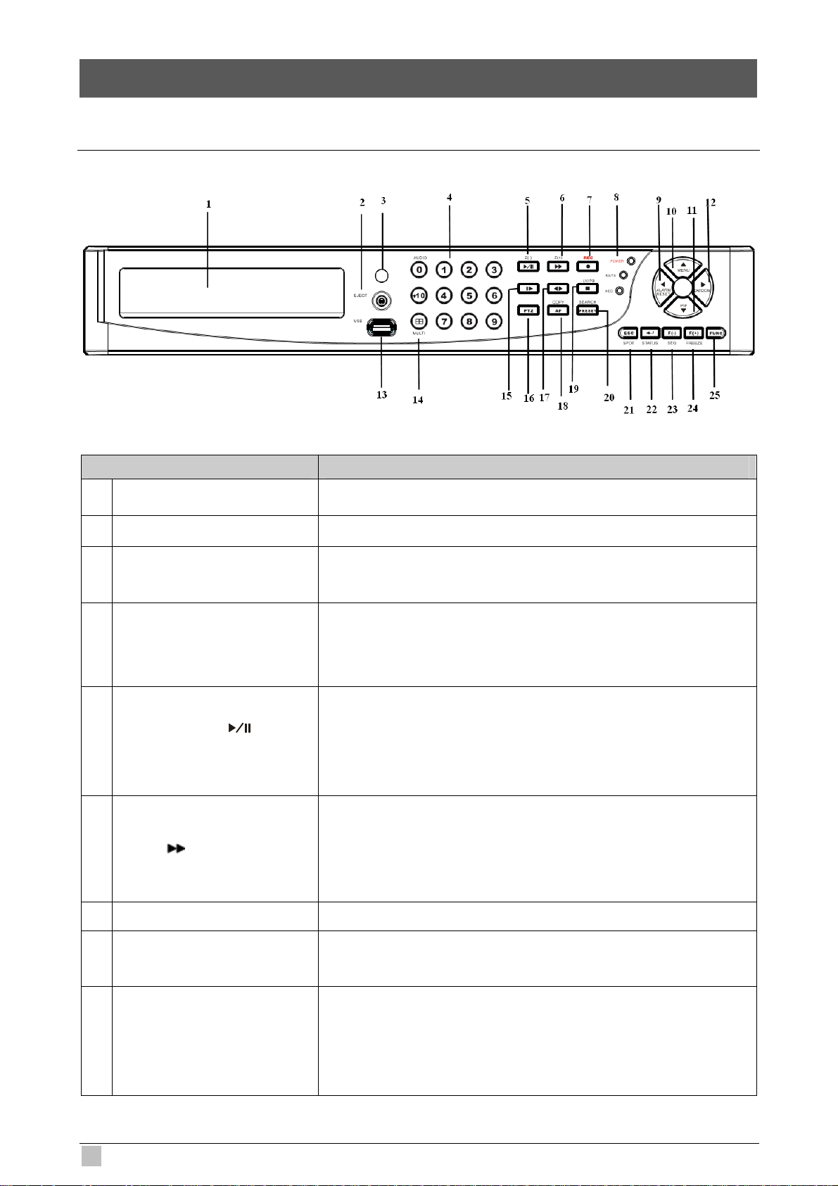
2.1 Front Panel
Item Description
2. PANELS and CONTROLS
1 DVD-RW A DVD-RW drive is installed in the front bay. (sold separately)
2 EJECT Press EJECT button to open/close the DVD-RW drive.
3 IR RECEIVER
NUMERIC BUTTON /
4
CHANNEL SELECT
PLAY / PAUSE
5
6
FAST
( ) /Z(+)
( ) / Z(-)
Infrared signal receiver for the IR remote controller. Do not block the
receiver as a clear line of sight is required for proper operation.
(a) selects a specific channel number to be displayed in full screen
(b) enter the numeric password when prompted
(c) number 0 for audio function
(a) Starts the playback of recorded data. By default, the playback
starts from the earliest recording.
(b) Toggles between playback and pause mode
(c) Zoom out (PTZ mode)
(a) Fast forward. Press this button repeatedly to toggle between 2X
normal playback speed through 128X normal playback speed.
(b) Zoom in (PTZ mode)
(c) Playback forward, picture by picture.
7
RECORD
8 STATUS LED
ALARM RESET / LEFT
9
DIRECTION BUTTON
8
( )
(W )
This button starts and stops the recording mode.
Displays the status of the DVR (standby), HDD read/write and
network transmission.
(a) resets the alarm buzzer
(b) left pans in PTZ mode
(c) navigates left in the menu screen
(d) moves the zoom box left in zoom mode
DVR-471 / DVR-1671 User Guide
Page 9

(a) accesses the main menu screen
MENU / UP DIRECTIONAL
10
BUTTON
PIP / LOOP PLAYBACK
11
CLEAR / DOWN
DIRECTIONAL BUTTON
DIGITAL ZOOM / RIGHT
12
DIRECTIONAL BUTTON
13 USB 2.0
14 MULIT
(S)
(T)
( X)
(b) tilts up in PTZ mode
(c) navigates up in the menu screen
(d) moves the zoom box up in zoom mode
(a) activates the picture-in-picture mode
(b) tilts down in PTZ mode
(c) navigates down in the menu screen
(d) moves the zoom box down in zoom mode
(e) clears the loop playback in playback mode
(a) enters digital zoom mode
(b) pans right in PTZ mode
(c) navigates right in the menu screen
(d) moves the zoom box right in zoom mode
The USB 2.0 port can be used to connect to numerous USB 2.0
backup devices.
This button is used to toggle between multiple display modes: 16,
13, 10, 9, 7 and 4 channel split screen display modes.
(a) Slow playback. Press this button repeatedly to toggle between
SLOW
15
16 PTZ / BOOKMARK
17
18 COPY / AUTO FOCUS
19 STOP (■) Switches the Playback mode to LIVE mode.
20 SEARCH / PRESET
21 SPOT MONITOR / ESC
( )/ IRIS CLOSE /
PIC BY PIC
DIRECT ION
( )
1/2 normal playback speed through 128 normal playback speed.
(b) Control the iris close in PTZ mode
(c) Playback backward, picture by picture
(a) enters PTZ control mode
(b) creates a bookmark during playback mode
(a) Change the playback direction.
(b) Control the iris open in PTZ mode
(a) enters the copy menu screen
(b) switches the PTZ camera to auto focus mode in PTZ mode
(a) enters the search menu screen
(b) sets the preset positions in PTZ mode
(a) Activates the spot monitor control
(b) Returns to previous menu screen
22 ENTER / STATUS / HOME
4/16-ch H.264 Digital Video Recorder
(c) Exits from various function and menu screen
(a) executes the selected function in the menu screen or enters the
selected submenu
(b) accesses the status window from the main screen
(c) returns the PTZ camera to “home” mode in PTZ mode
(d) increases the digital zoom ration in zoom mode
Page 10

AUTOMATIC SEQUENCE /
23
FOCUS OUT / DECREASSE
VALUE / SECTION A
(a) activates and deactivates the automatic channel sequence
(b) focuses out in PTZ mode
(c) decreases the value of a selection in the menu screen
(d) sets the starting point for loop playback in playback mode
FREEZE / FOCUS IN /
24
INCREASE VALUE /
SECTION B
25 FUNCTION
(a) freezes the live screen
(b) focuses in PTZ mode
(c) increase the value of a selection in the menu screen
(d) sets the ending point for loop playback in playback mode
Use with other buttons.
10
DVR-471 / DVR-1671 User Guide
Page 11
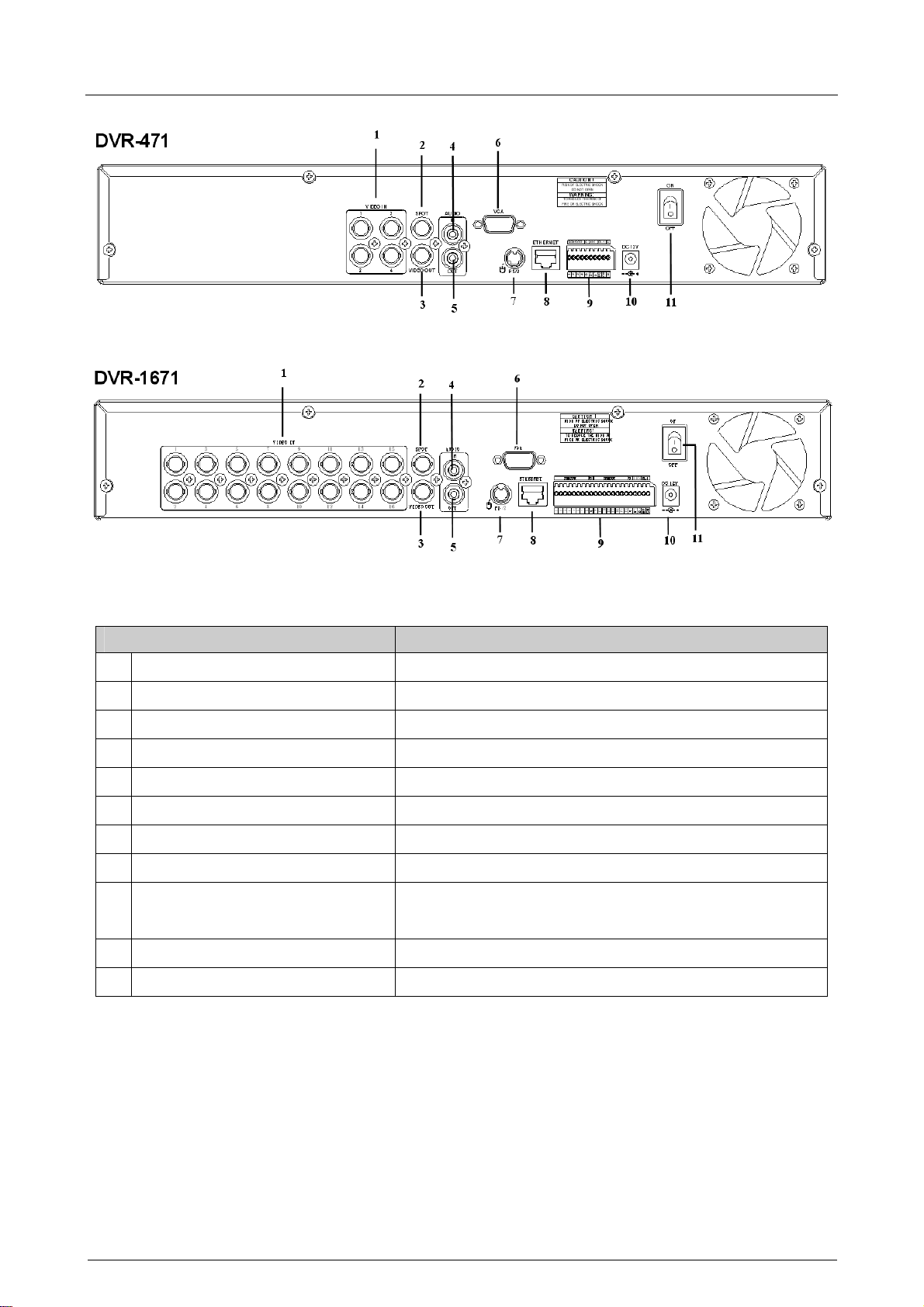
2.2 Rear Panel
Item Description
1 VIDEO IN BNC input ports for cameras
2 SPOT BNC output port for spot monitor
3 VIDEO OUT BNC output port for the main monitor
4 AUDIO IN RCA input port for an audio signal
5 AUDIO OUT RCA output port for an audio signal
6 VGA Output port for the VGA monitor
7 PS/2 PS/2 mouse connection port
8 ETHERNET Port for 10/100Mbps Ethernet
Input terminal blocks for alarm signals/Terminal blocks of
9 SENSOR / RS-485 / RELAY OUT
RS-485 / Relay output terminal blocks
10 POWER IN Socket for DC 12V power adapter
11 POWER SWITCH Switch to turn the power on/off
4/16-ch H.264 Digital Video Recorder
Page 12
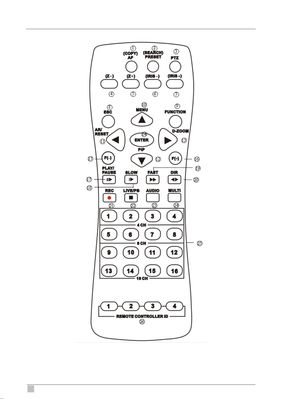
2.3 Remote Controller
12
DVR-471 / DVR-1671 User Guide
Page 13
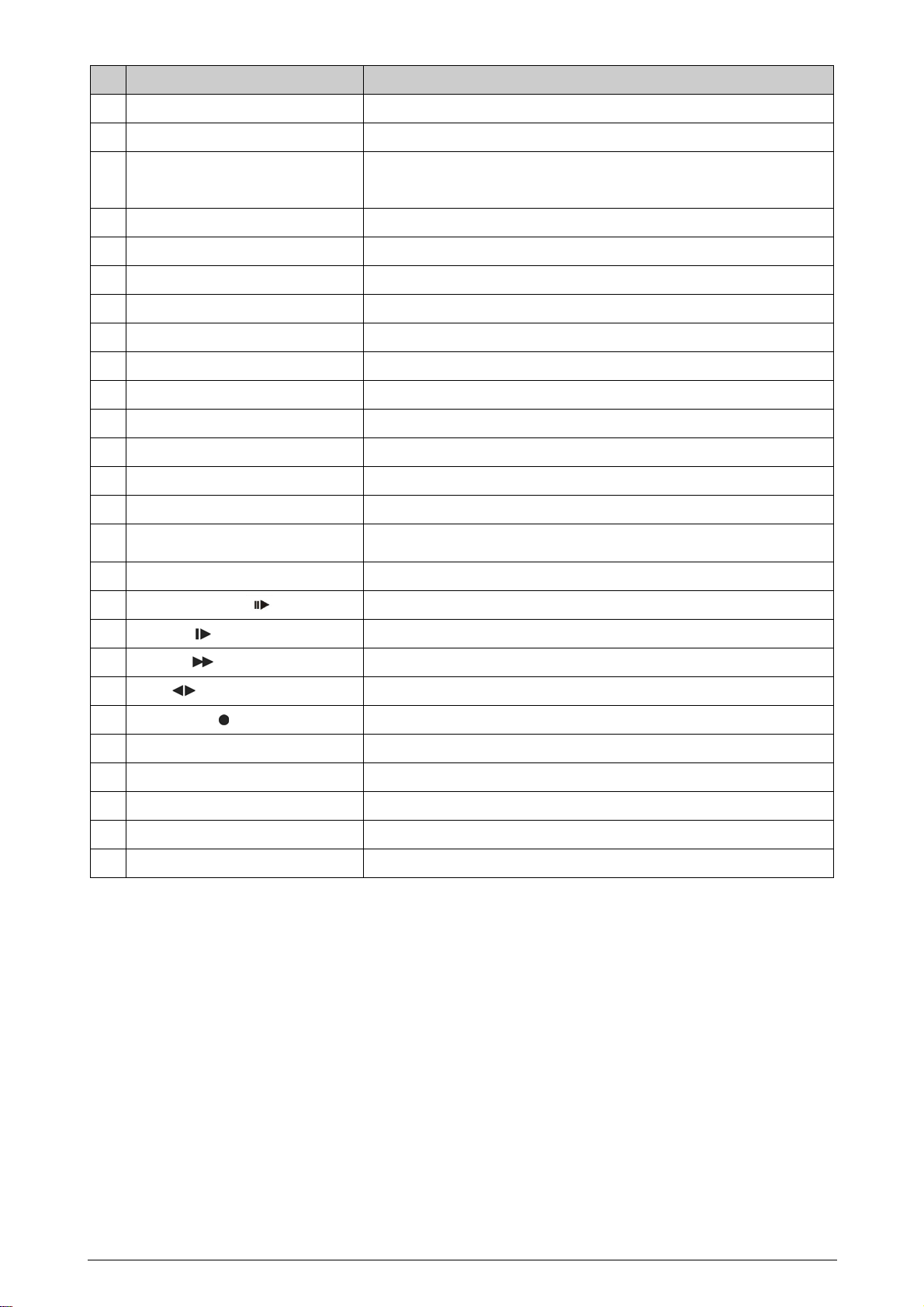
Button Name Description
1 COPY/AF
2 (SEARCH) / PRESET
3 PTZ / BOOKMARK
4 Z-
5 Z+
6 IRIS -
7 IRIS+
8 ESC
9 FUNCTION
10 ( ▲ ) / MENU
11 AR/ RESET / ( )
12 ( ▼ ) / (PIP)
13 DIGITAL ZOOM / ( )
14 ENTER
15 F(-)
16 F(+)
Enter the COPY menu / Auto Focus Mode (PTZ control mode)
Enter the SEARCH menu / sets the preset positions in PTZ mode
Enter PTZ control mode / creates a bookmark during playback
mode
Zoom Out (PTZ control mode)
Zoom In (PTZ control mode)
Control the iris close in PTZ mode
Control the iris open in PTZ mode
Exit / Activates the SPOT monitor control
Use with other buttons
Up directional button / Enter Menu Setup
Alarm reset / Left directional button
Down directional button / Enter the PIP mode
Enter Digital Zoom mode / Right directional button
Enter / Enter the STATUS menu
Decreases the value of a selection / Activates and deactivates the
automatic channel sequence
Increases the value of a selection / Freezes the LIVE screen
17
PLAY / PAUSE (
18
SLOW (
19 FAST ( )
20 DIR ( )
21 RECORD ( )
22 LIVE/PB / (■)
23 AUDIO
24 MULTI
25 CAMERA BUTTONS
26 REMOTE CONTROLLER ID
)
)
PLAY / PAUSE
Slow playback
Fast forward
Change the playback direction
Starts and stops the recording mode
Switches the LIVE mode and Playback mode / STOP
Audio function
Multi display mode
Numeric button / Channel select
REMOTE CONTROLLER ID
4/16-ch H.264 Digital Video Recorder
Page 14
2.4 Mouse Control
LIVE MODE
Single Channel Display
Change from Single-Channel to Multi-Channel Display Double left click
MENU MODE
Enter MENU Right click
Select / Enter Double left click
Return to Previous Page Double right click
Value Change Turning the wheel scroll
Move the cursor to the desired channel and
double left click.
14
DVR-471 / DVR-1671 User Guide
Page 15
3. INSTALLATION
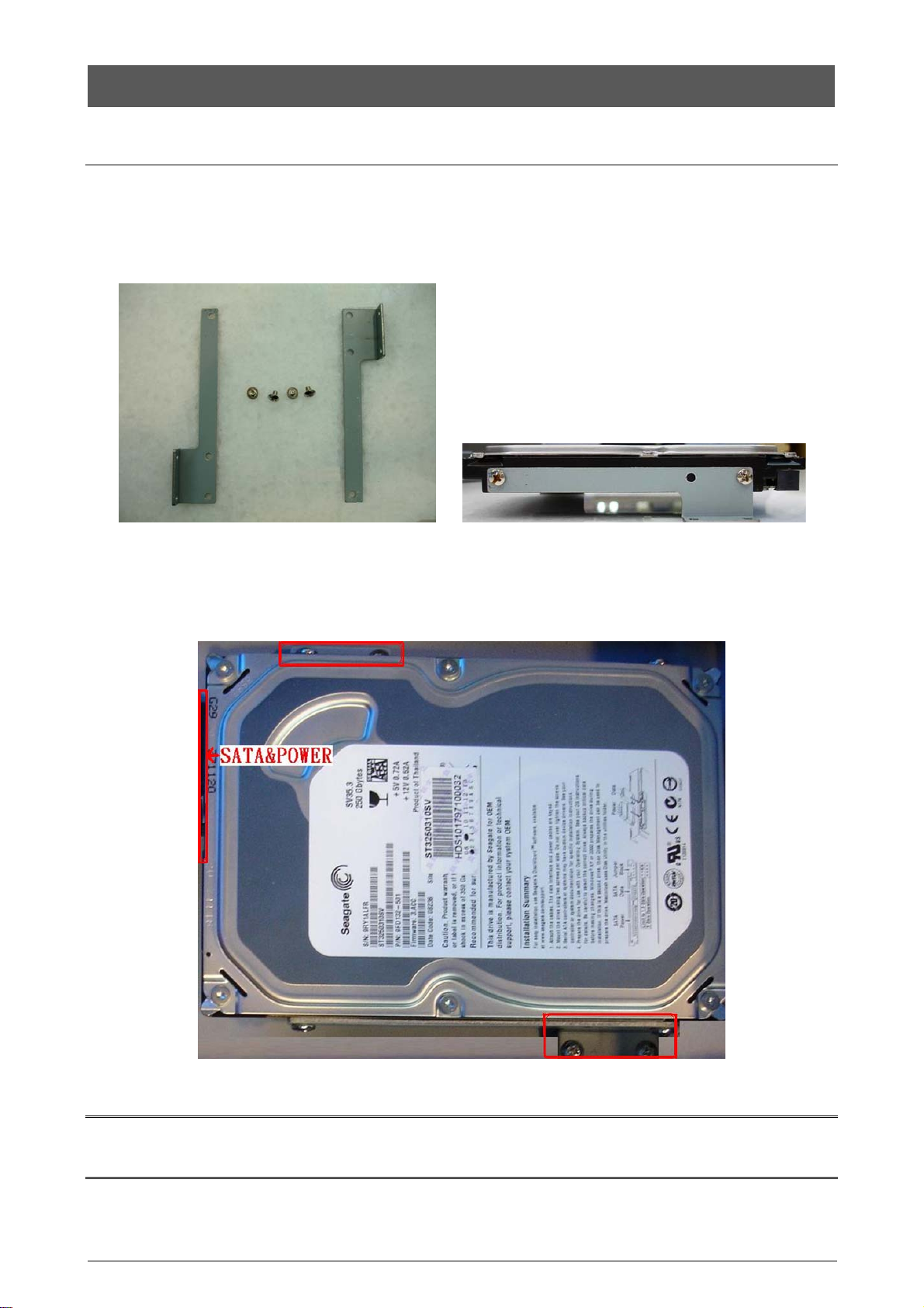
3.1 HDD Installation
Step 1:
Lock HDD holder symmetrically in the two sides of HDD with racks and screws.
Make sure the position between HDD and racks.
Note:
The HDD must be installed before the DVR is turned on.
4/16-ch H.264 Digital Video Recorder
Page 16
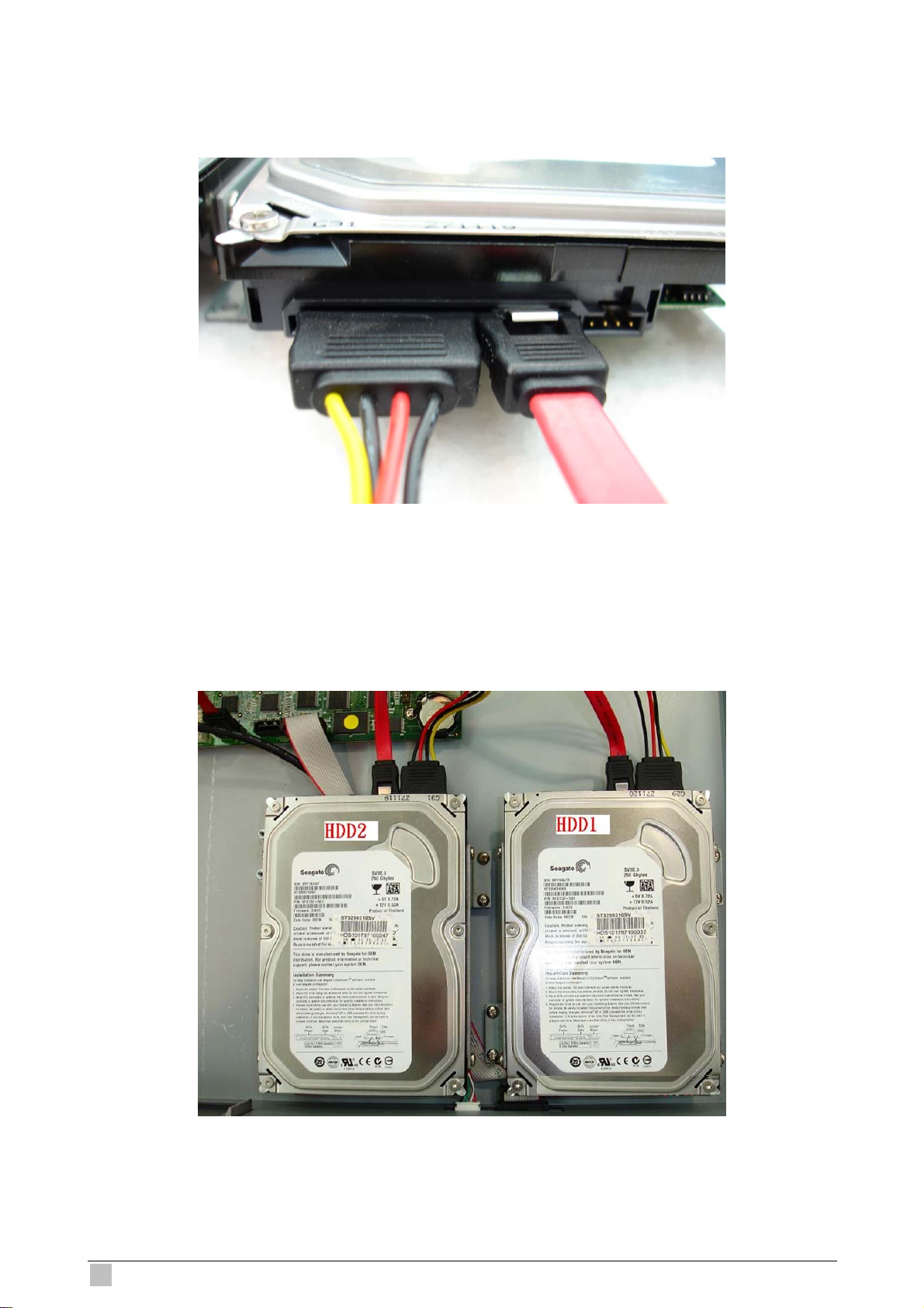
Step 2:
Insert the SATA cable and power cable into SATA HDD.
Step 3:
Lock the HDD onto DVR machine.
16
DVR-471 / DVR-1671 User Guide
Page 17
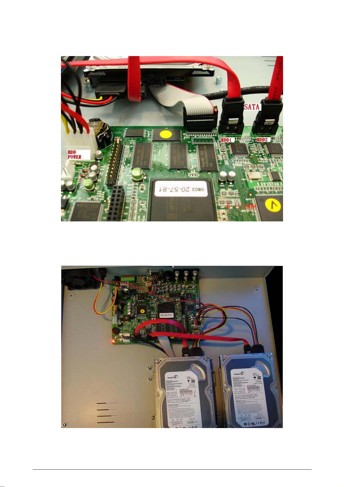
Step 4: Insert the SATA cables into the sockets on the main board. Make sure the HDD1, 2
cables insert into HDD1, 2 sockets.
Now, the installation was finished
4/16-ch H.264 Digital Video Recorder
Page 18
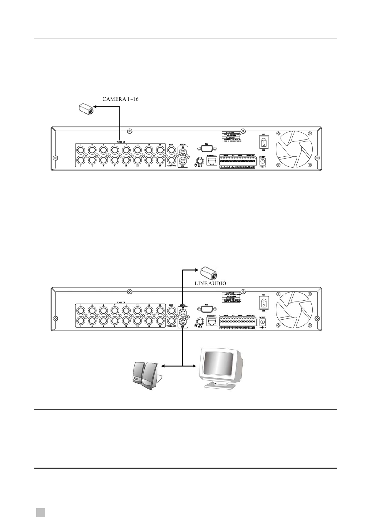
3.2 Devices Connection
Camera Input
Connect a female BNC connector of each camera to a male BNC connector, “CAMERA IN”
port.
Audio Input
Connect the RCA Line Jack of the relevant equipment (for example, a camera with a built-in
microphone) to the AUDIO IN port.
Audio Output
Connect the RCA Line output to a monitor with a built-in speaker.
Note:
1. This DVR can be connected only with a line audio and not support a microphone for audio input
and output. To record audio should be enable in the AUDIO setup at the MENU setup.
2. You can hear the audio under LIVE mode and Playback mode. And select any one channel’s
audio and image input from full-screen mode or multi-display mode.
18
DVR-471 / DVR-1671 User Guide
Page 19
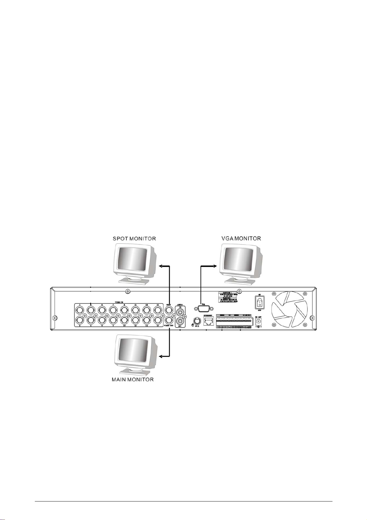
DVR supports two types of monitor output, one is Composite output (BNC connector); the
other one is VGA output (DSUB-15). But you can just select one monitor output type at a
time.
Composite Output:
(1) Power off
(2) Press the MENU button and CH3 button at the same time
(3) Power on
(4) When you hear a beep sound, it means images already output to the Composite port.
Now you can release the buttons.
VGA Output:
(1) Power off
(2) Press the MENU button and CH4 button at the same time
(3) Power on
(4) When you hear a beep sound, it means images already output to the VGA port. Now
you can release the buttons.
4/16-ch H.264 Digital Video Recorder
Page 20
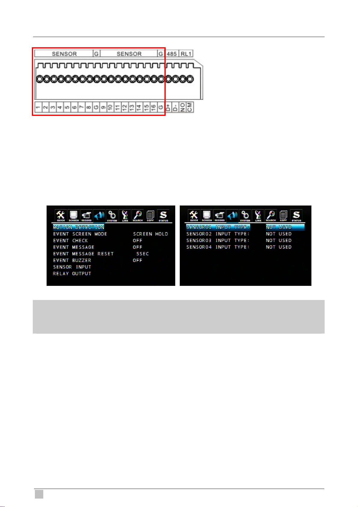
3.3 Sensor Input
16CH: SENSOR 1~SENSOR 16
4CH: SENSOR 1~SENSOR 4
3.3.1 Sensor Input Menu Setup
Enter EVENT -> SENSOR INPUT menu to select the correct sensor input type which
connected with DVR.
Select the right sensor type according to the type of installed sensor with the unit.
- NORMAL OPEN: The sensor is open in normal times.
- NORMAL CLOSE: The sensor is close in normal times.
- NOT USED: No sensors are connected to the DVR unit
20
DVR-471 / DVR-1671 User Guide
Page 21
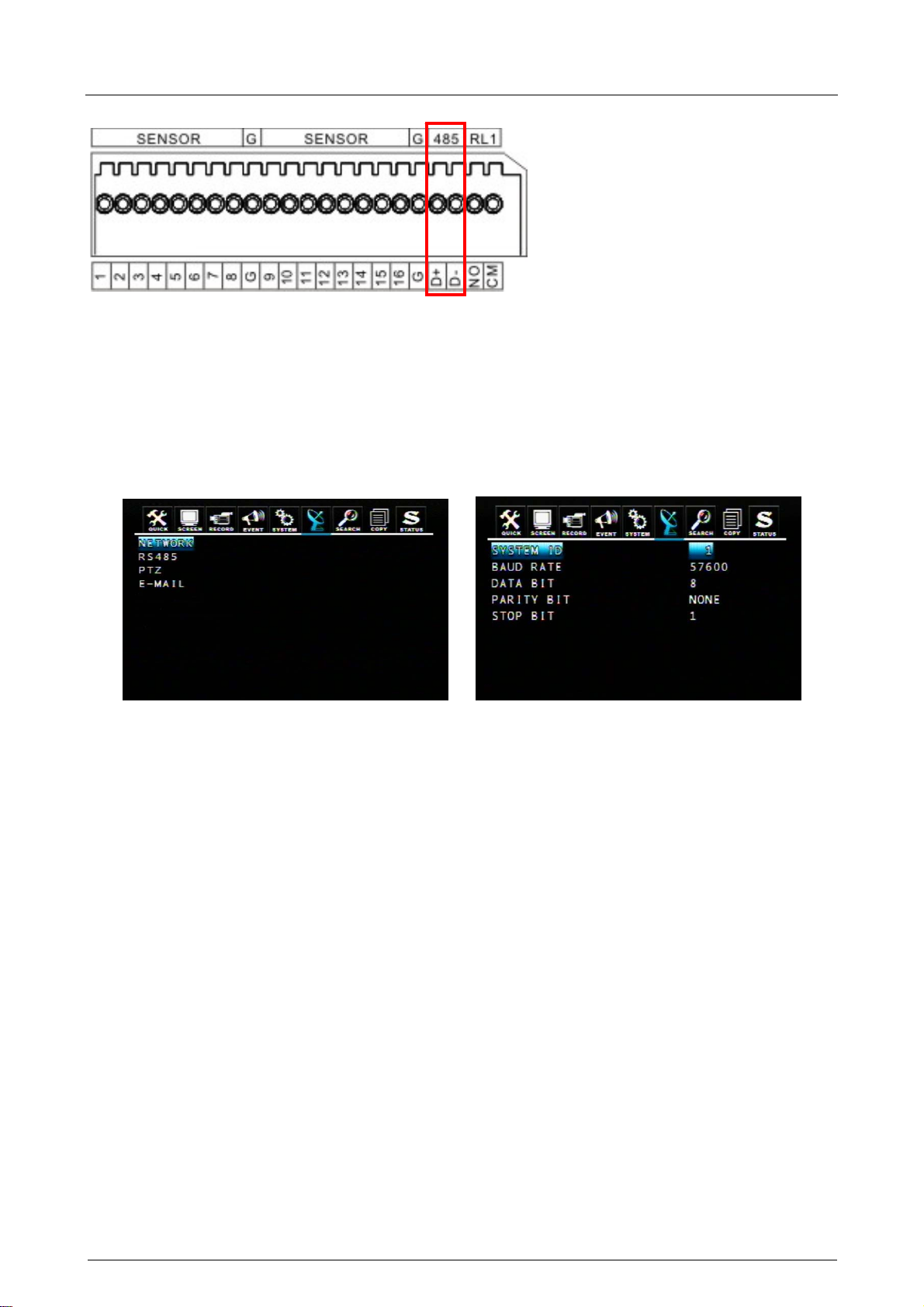
3.4 RS-485 interface
RS485 is use for connect to external device, such as keyboard or PTZ camera.
3.4.1 RS-485 Menu Setup
Enter LINK -> RS485 menu to set the parameters of RS-485 device which connected with
DVR (The parameters must the same with the device).
4/16-ch H.264 Digital Video Recorder
Page 22
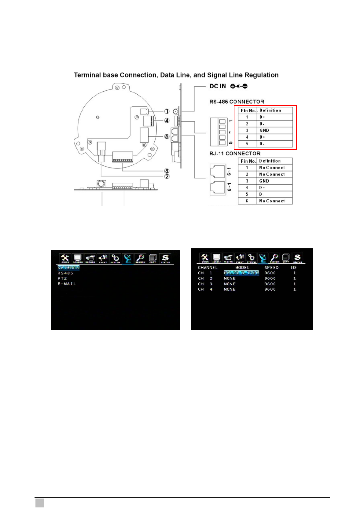
3.4.2 PTZ Camera Installation
Connect the PTZ camera to DVR RS-485 interface (D+ to D+; D- to D-), and then connect
the camera output to the desired channel.
Enter LINK -> PTZ menu to set the parameters of PTZ camera which connected with DVR
(The parameters must be same with PTZ camera).
22
DVR-471 / DVR-1671 User Guide
Page 23
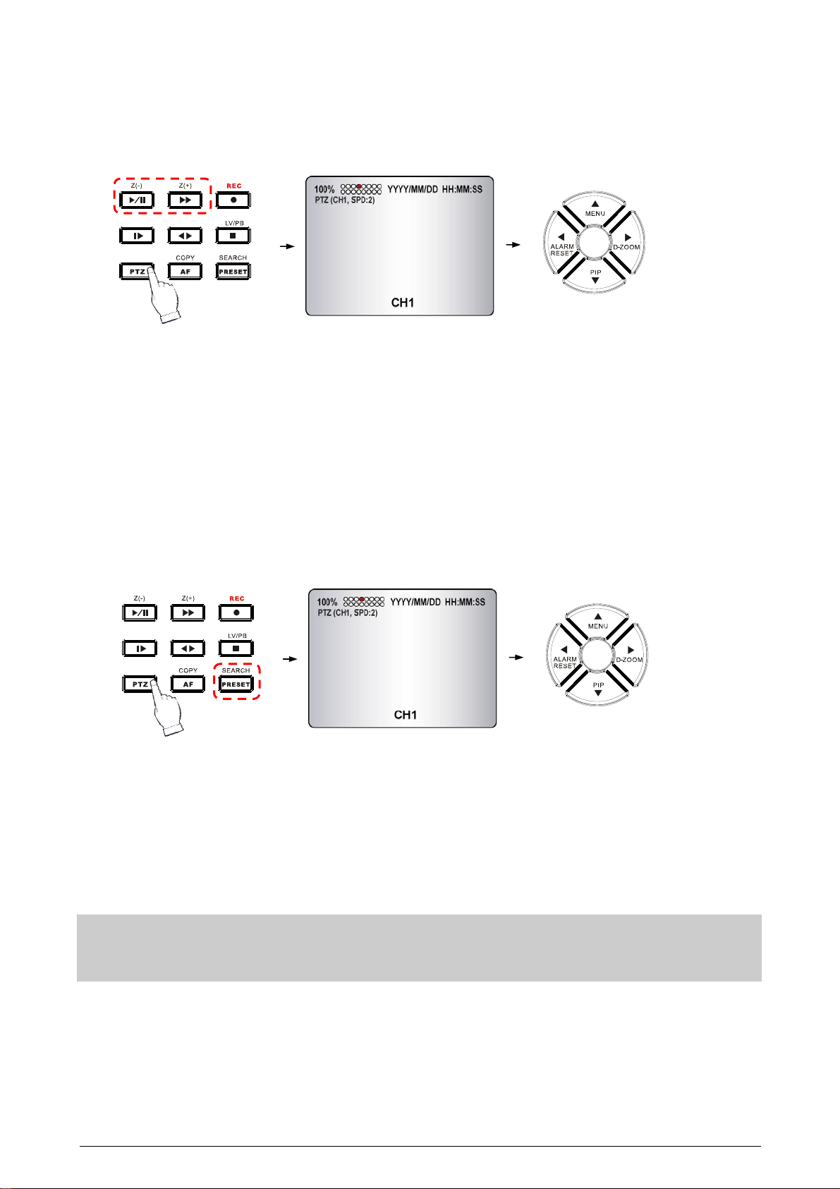
3.4.3 PTZ Camera Operation
1. Select the desired PTZ camera channel.
2. Press the PTZ button to enter the PTZ mode.
3. Use the direction buttons to change camera position.
4. Press Z(+) and Z(-) buttons to control the camera zoom in and zoom out.
5. Press the PTZ button again to exit the PTZ mode.
3.4.4 PTZ Camera Preset Mode
1. Select the desired PTZ camera channel.
2. Press the PTZ button to enter the PTZ mode.
3. Press the PRESET button to enter the “PTZ(PRESET)SET” mode.
4. Use the direction buttons to adjust the camera position you want.
5. Press one number button to remember this preset camera position, for example: press
the “1” button, it means the position of the preset point 1.
6. Press the PRESET button again to enter the “PTZ (PRESET) MOVE” mode.
7. Press the number button, you can move the camera to the preset point you want.
8. Press the PRESET button again to back to the normal PTZ mode.
9. Press the PTZ button again to exit the PTZ mode.
Preset point is a convenient usage of PTZ camera. It is a preset user-defined camera position; user can
move the camera position very quickly when needed.
Total programmable capacity of 16 preset locations.
4/16-ch H.264 Digital Video Recorder
Page 24
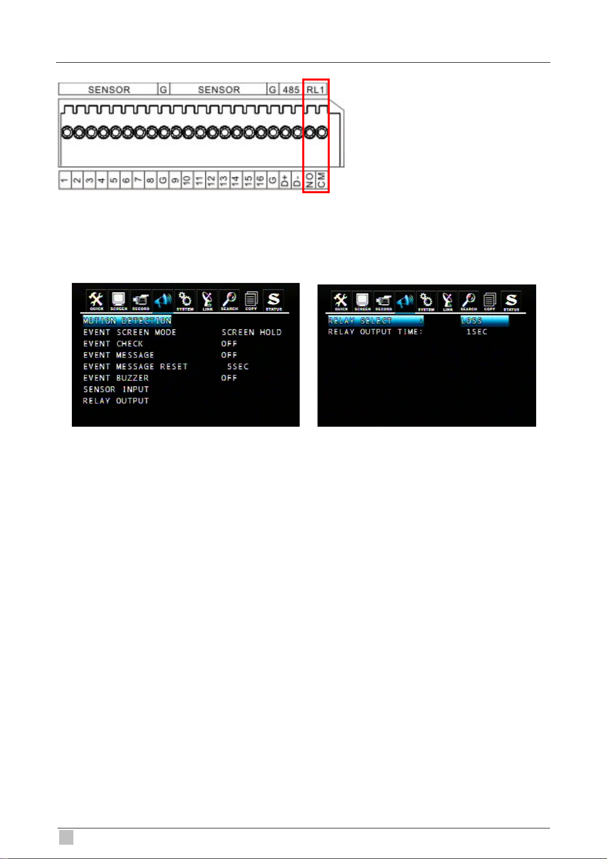
3.5 Relay Output
The relay device should be set to NO (Normal Open) and it will change to NC (Normal
Close) when an event has been triggered.
Enter EVENT -> RELAY OUTPUT menu to select the Relay type which connected with
DVR.
DVR provides a relay output interface; the following events will trigger off the relay signal:
RELAY SELECT
<Event Type>
ALARM: Sensor Input
LOSS: Video Loss
MOTION: Motion Detection
RELATY OUTPUT TIME: 1~30 sec.
According to the time set, the buzzer starts beeping while the event is happening.
RELAY SELECT
<System Type>
HDD ERROR: Once hard disk has failed, it will change the relay device to NC.
POWER (NC): Please set the relay device to NC so that once power-loss occurs, it will
change to NO.
USER: The relay output can be manully changed. To change NO to NC, press FUNC and
then press F(+). Changing NC to NO, press FUNC and then press F(-).
REC: Once recording has stopped, it will change the relay device to NC.
NOT USED: Disable relay output function.
24
DVR-471 / DVR-1671 User Guide
Page 25
4. BASIC OPERATION and SETUP
4.1 Basic Operation
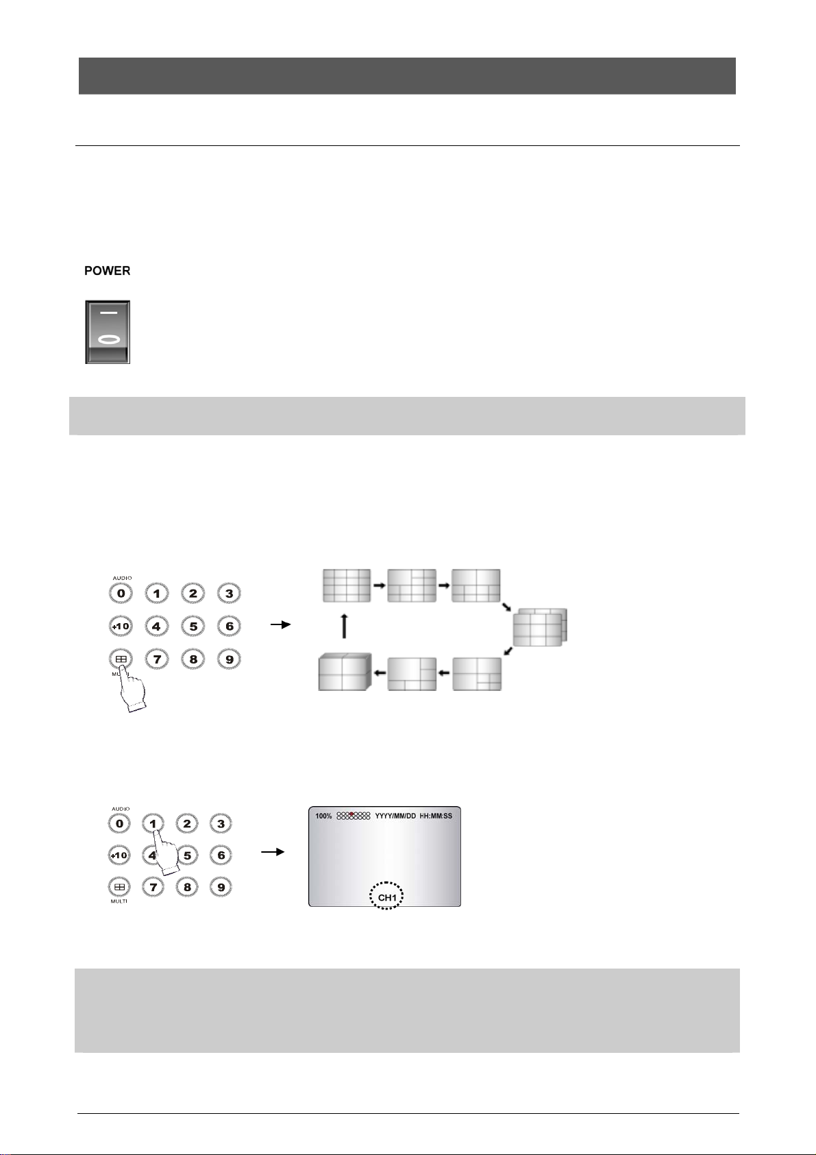
4.1.1 Power On/Off
After connecting power adaptor and other devices (HDDS) with this DVR, turn the power on.
a.
The video signal system (NTSC or PAL) is automatically detected.
b. Power Failure Recovery
This DVR automatically reverts back to programmed record parameters upon
If there is no video signal, the video signal system is set to NTSC. Do not input the PAL type video signal or it
may cause the DVR’s malfunction. In this case, turn off and on again.
power restoration.
4.1.2 Screen Display
a. Multi display
To change a single camera display to the multi camera, press the MULTI button.
b. Full screen display
Press the desired camera number button to display on the monitor.
NOTE:
-Use the +10 Button when you select two digit camera numbers.
EX) Camera Number 12 = Press the +10 Button, and then press the No. 2 Button.
-CAMERA/NUMBER INPUT buttons are used to input the password in the password lock function as well.
4/16-ch H.264 Digital Video Recorder
Page 26
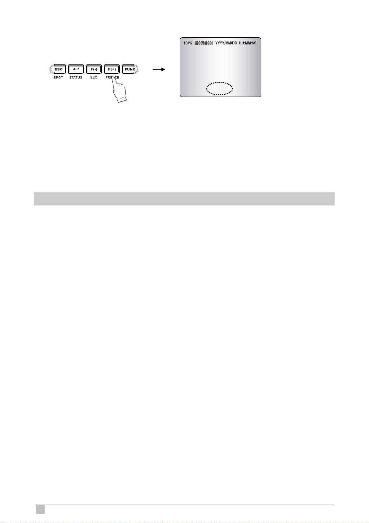
c. Freeze
FREEZE
This function allows users to freeze live view mode at any given time. 4CH DVR supports
only single screen mode. Press [FREEZE] at single screen mode to freeze the image and
press again to release this function.
16CH DVR can support both single and multi screen mode. The operation is the same as
4CH DVR for single screen mode. For multi screen mode, press [FREEZE] at multi live
screen, the message will be shown at upper-left, but no channels will freezed. Then press
the channel users want to freeze, the message will be shown at camera title. Press next
channel to stop others. Press [FREEZE] again to release this function.
- FREEZE function is not available, when auto mode is selected.
d. LIVE / Playback mode switching
Press the LV/PB (■) button in the Playback mode, you can switch to the LIVE monitoring
mode.
26
DVR-471 / DVR-1671 User Guide
Page 27

4.1.3 System Status
① Press the “STATUS” button, the SYSTEM STATUS menu will appear.
② Select the item you want: DVR Status, Network Status or Recording Bitrate, you can see
the detail information.
③ Press the “ESC” button to exit the menu.
DVR status: Network status:
Recording Bitrate:
This page shows the present RECORDING
BITRATE of DVR. High bitrate means it’ll
need more HDD space.
4/16-ch H.264 Digital Video Recorder
Page 28

4.1.4 Audio Control
Audio ON/OFF: Press the FUNCTION button and then press the “AUDIO (0)” button to
open/close the DVR audio function. You can hear audio of selected channel regardless of
monitoring screen.
4.1.5 PIP Mode
① Select a single camera in live view, and then press the PIP button and the following
screen will be displayed (For example: CH1).
CH2
CH1
② Select the desired camera that will be displayed on the PIP screen (For example: CH2,
but can not select the same camera with present (CH1)).
③ Press the ENTER button to make the 2 times PIP screen size and use the S, T, W, X
buttons to move the position of PIP screen.
④ Press the ESC button to exit this mode.
28
DVR-471 / DVR-1671 User Guide
Page 29

4.1.6 Digital Zoom
Select the desired camera channel.
①
Press the D-ZOOM button, the indication screen appears on the main screen.
②
Press S, T, W, X buttons to select the desired location.
③
Press the ENTER button to change the zoom size x2 ~ x4.
④
Press the ESC button to exit this screen.
⑤
4.1.7 Menu Operation
Press the MENU button to enter the main menu screen.
①
Move the cursor to desired position using the S,T,W,X buttons, then press the
②
button to enter each submenu.
Change the value using the F(-),F(+) buttons or truning the wheel scroll of mouse.
③
Select the item to exit the menu setup, you will see the following screen:
④
Select save or not, then you can exit the menu setup.
If there is no input for 1 minute during the menu screen display, the menu screen will be closed
automatically without saving of changed value.
4/16-ch H.264 Digital Video Recorder
Page 30

4.2 Screen
4.2.1 Auto Sequence
To set the length of time for switching each channel in the AUTO SEQUENCE mode. The
value is from 1SEC to 60SEC and the default is “3SEC”.
ADD AUTO SINGLE: If selected OFF, every single channel will be skipped in the AUTO SEQUENCE
mode. The default is “OFF”.
VIDEO LOSS SKIP: If selected ON, every VIDEO LOSS channel will be skipped in the AUTO SEQUENCE
mode. The default is “ON”.
30
DVR-471 / DVR-1671 User Guide
Page 31

Auto Sequence Display
<ADD AUTO SINGLE: ON>
- Press the SEQ button, each screen display will be automatically switching according to
the AUTO SEQUENCE setup.
- Press the SEQ button and again to exit the AUTO SEQUENCE mode.
NOTE: 1. If an event takes place, the AUTO SEQUENCE mode will be cancelled.
2. Do not set 0 SEC to any display mode.
4.2.2 Display
To decide which information will be displayed on the screen:
HDD Free Space
If the value is ON, the remaining capacity of the fixed HDDs will be displayed on the screen.
The default is ON.
HDD Free Space Mode
The default is “PERCENT”.
PERCENT: Remaining capacity of the fixed HDDs will be displayed on the screen in percent.
GIGABYTE: Remaining capacity of the fixed HDDs will be displayed on the screen in gigabyte.
Record Status
ON: Displaying the recording status of each channel on the screen. The default is ON.
Clock Display
ON: The date and time will be displayed on the screen. The default is ON.
4/16-ch H.264 Digital Video Recorder
Page 32

Date&Time Mode
Choose from “YY/MM/DD” or “MM/DD/YY” or ”DD/MM/YY”. The default is
“YY/MM/DD”.
YY/MM/DD: All date and time will be displayed in numbers.
Ex. 2005/01/01 00:00:00
MM/DD/YY: the month section will be displayed in character.
Ex. JAN. 01 2005 00:00:00
DD/MM/YY: the month section will be displayed in character.
Ex. 01. JAN 2005 00:00:00
Title Display
ON: Each channel title will be displayed on the screen. The default is ON.
Title Mode
Title can be displayed as TEXT or BITMAP (a graphics file) format. The default is TEXT.
TEXT: Use the characters or symbols in the CHARACTER TABLE as Title name.
BITMAP: If you need other language or characters to name the Title, you can download the bitmap file
through the client viewer software. Please refer to 9.4.10.
Border Color
To define the color of the border line under multi display mode. The default is
WHITE.
Remote Control ID
ON: The remote controller ID will be displayed on the screen. The default is OFF.
4.2.3 Title
To name or modify the channel title.
32
DVR-471 / DVR-1671 User Guide
Page 33

Press the ENTER button after selecting desired channel and the following screen appears:
Select the character using the S, T, W, X buttons and then press button. Press the
ESC button to exit the character table.
4.2.4 Multi Screen
Enter one of the five modes (4, 7, 9, 10, 13 for 16CH) and change the selected channel to
multi-split screen. Turn the display on and then it will be shown in the sequence by pressing
MULTI or SEQ button on the front panel.
4.2.5 Covert
ON: The images of the selected channel will be hid and displayed in black screen,
but doesn’t affect the recording status. The default is OFF.
SELECT: “LV&PB&NW”, “PB&NW”, “LV&NW”, “LV&PB”, “NETWORK”, “PLAY” and “LIVE”.
LV(LIVE): To covert selected channels on live screen.
PB(PLAY): To covert selected channels on playback screen.
NW(NETWORK): To covert selected channels on network viewer screen.
COVERT TITLE DISPLAY: Show the “COVERT” text in the camera title position or not.
4/16-ch H.264 Digital Video Recorder
Page 34

4.2.6 SPOT
SPOT MODE
- MANUAL: Manually select the channel of spot monitor.
- EVENT: Event channel will be displayed automatically on spot monitor.
- SEQUENCE: Every single channel will be switching and displaying in sequence.
SPOT SEQUENCE TIME
The duration of spot sequence can be set from 1SEC to 60SEC. The default is
3SEC.
VIDEO LOSS SKIP
If you select “ON”, loss images will be skipped. The default is ON.
SPOT Mode Operation
Manual Mode
Press the “SPOT” button on the front panel to toggle “SPOT” mode indicated on the main
monitor.
Press a camera button to display that camera on the spot monitor.
34
DVR-471 / DVR-1671 User Guide
Page 35

4.2.7 Camera
Change the values shown on the screen to adjust the BRIGHTNESS, CONTRAST, HUE and
SATURATION of each channel.
The value is from 0% to 100% and the default is “50%”.
4.3 System
4.3.1 HDD
REC HDD INITIALIZE: Select YES and press ENTER button to format the HDD.
Note: All data will be cleared after initialized. Please be careful.
4/16-ch H.264 Digital Video Recorder
Page 36

4.3.2 Clock
System clock adjustment.
DATE&TIME
Manually adjust the Date and Time values.
- DATE: YYYY/MM/DD YEAR/MONTH/DAY
- TIME: HH:MM:SS HOUR:MINUTE:SECOND
TIME ADJUST
If the INTERNET TIME ADJUST is “ON”, system time will be adjusted to the time offered by the
①
internet server.
If the INTERNET TIME ADJUST is “ON”, please set the IP address of SELECT TIME SERVER.
②
Set the correct TIME ZONE standardizing GMT (Greenwich Mean Time).
③
If the DAYLIGHT SAVING TIME is “ON”, please set the starting date and time and end date.
④
36
DVR-471 / DVR-1671 User Guide
Page 37

4.3.3 Video Standard
Select from “AUTO”, “NTSC” or “PAL”. The default is “NTSC”. If you select “AUTO”, this
DVR can detect NTSC/PAL automatically.
4.3.4 Language
Select the system language. Available languages: ENGLISH, POLISH, SPANISH,
RUSSIAN, CHINESE (T) (Traditional Chinese), FRENCH, TURKISH, GERMAN, ITALIAN,
PORTUGUESE.
4.3.5 Remote Control ID
If you are operating more than one DVR in the same place and wish to use the remote
controller, the remote controller ID setup is required. Otherwise, do not change the default
set value and “ALL” should be selected.
Creates the Remote controller ID:
Select one of the numbers 11~14, 21~24, 31~34, 41~44, and then press the same number
button on the supplied remote controller before the operation.
4.3.6 Key Echo
- ON: The beep sounds when you press any buttons on the front panel.
- OFF: The beep does not sound.
4.3.7 Advanced Setup
4/16-ch H.264 Digital Video Recorder
Page 38

4.3.7.1 Password Check
Some operation can be protected by password check.
Admin password has the highest manager authority of this DVR. Default user is Admin.
Please note! If you forget admin password, there is no way to access this DVR
again.
If PASSWORD CHECK is ON, when user using following functions, system will request the password:
Record, Search&Playback, Copy, Live Audio, DVR Menu Setup, DVR Status checking and PTZ control.
4.3.7.2 Set Passwork
Select the administrator or user1~4 to change the password and then press “ENTER”
button.
Insert your desired password and retype again using the CAMERA/ NUMBER INPUT
buttons.
NOTE:
- You can use only 0~9 number buttons to setup the PASSWORD.
- The default passwords as:
ADMIN is 11111111,
USER1 is 22222222,
USER2 is 33333333,
USER3 is 44444444,
USRE4 is 55555555.
CAUTION:
For security reason, please change the password after purchasing
38
DVR-471 / DVR-1671 User Guide
Page 39

4.3.7.3 User Authority
You can give different user with independent authority by this setting. ON means user can
use the specific function.
4.3.7.4 DVR Menu Setup
1. Menu Initialize
If select YES, all menu setting will be restore to factory default.
NOTE: After initialized, HDD data will not be deleted.
4/16-ch H.264 Digital Video Recorder
Page 40

2. LOAD MENU FROM FILE
To download the DVR menu settings from file that was saved in the USB storage device.
3. SAVE MENU TO FILE
Save the menu settings to the USB storage device.
Note: To copy and upload the menu setting only from front USB port.
4.3.8 Firmware Upgrade
You can update the DVR firmware through the USB interface. Insert the USB device with
the all.dvi file into DVR and press YES to update the firmware.
40
DVR-471 / DVR-1671 User Guide
Page 41

5. RECORD OPERATION and SETUP
5.1 Record Operation
The DVR provide three methods of recording for your choice as following:
1. Manual Recording: You can just press the
LIVE monitoring time. Press the RECORD button again to exit recording mode.
2. Schedule Recording: You can prearrange the schedule recording time (RECORD -> RECORD SETUP) by
applying Front Panel Control or Mouse Control.
Front Panel Control:
Select (▲/▼/◄/►) the desired record time on the RECORD PROGRAM schedule, and then press Z(+)
button to enable schedule record. The time point you’ve selected becomes color yellow. When the time
matches the setup, DVR will start recording according to the RECORD PROGRAM previously setup. To
cancel schedule record, please move the cursor to the yellow color time point and then press Z(-) button.
Move the cursor to any time point on the vertical ALL roll to enable the record schedule on the time point of
the whole horizontal roll.
Mouse Control:
Select (click-on) the desired record time on the RECORD PROGRAM schedule, and then click the yellow
rectangle icon (on the top right hand corner) to enable schedule record. The time point you’ve selected
becomes color yellow. When the time matches the setup, DVR will start record according to the RECORD
PROGRAM previously setup. To cancel schedule record, please move the cursor to the yellow color time
point and then click on the yellow rectangle icon. Move the cursor to any time point on the vertical ALL roll to
enable the record schedule on the time point of the whole horizontal roll.
button on the front panel during any
Rectangle
Vertical ALL Roll
3. Event Recording: DVR provides many kinds of Event setup; VIDEO LOSS, MOTION DETECTION
and ALARM; if the event occurs, the event record will be started.
4/16-ch H.264 Digital Video Recorder
Page 42

Recording status will be shown on the screen as different colors ( ) according to the recording
type:
- “
(Yellow) ” : Manual Recording mode
(Green) ” : Schedule Recording mode
- “
- “
(Red) ” : Event Recording mode (Motion detection/ Video loss/ Sensor)
(White) ” : Not Recording
- “
These three recording mode all needs a corresponding RECORD SETTINGs such as IMAGE SIZE,
RECORD FRAME… DVR will follow the menu setup to do the recording.
5.2 Quick Setup
This menu is simply used when user want to change just a few important settings.
QUICK SETUP
If QUICK SETUP setting is “ON”, DVR will record data according to the QUICK SETUP settings.
If QUICK SETUP setting is “OFF”, DVR will record data according to the Record Setup settings.
IMAGE SIZE:
NTSC: 720x480/ 720x240/ 360x240
PAL: 720x576/ 720x288/ 360x288
RECORD FRAME
Select the desired frame rate for normal recording. If you enable the QUICK SETUP, all the manual recording,
schedule recording and event recording will use the average record frame to record. For example, if the total
record frame is 120, the average record frame for each camera in a 16CH DVR is 7.5 (120 / 16 = 7.5).
42
DVR-471 / DVR-1671 User Guide
Page 43

NOTE:
- Recording frame rate will be: Total frame rate of resolution / Channels
For example:
① 16CH DVR have a total of 240/200(NTSC/PAL) frame rates with 360x240 resolution.
② When you select 360x240 in the quick setup, you will have 240/16channel=15IPS per channel.(NTSC)
- Bigger resolution will have a better picture quality but the file size is bigger and the available frame rate
will reduce accordingly. (720x480 is approximately 2 times bigger file size than 720x240, 720x240 is
approximately 2 times bigger file size than 360x240)
EVENT
Select a kind of EVENT of “ALL”, “ALARM”, “V-LOSS”, “MOTION”, “ALARM&LOSS”, “ALARM&MOTION”,
“LOSS&MOTION”, “OFF”. The default is “ALL”.
If you want to select all kind of event, choose “ALL” and if you don’t want event recording, choose “OFF”.
PRE RECORD TIME
When video loss, alarm or motion is detected, DVR will store pre-recorded data during the selected time. The
pre-recording time can be set from 0 second to 5 second and the default is “5”.
POST RECORD TIME
When video loss, alarm or motion is detected, DVR will store post-recorded data during the selected period.
The post-recording time can be set from 0 second to 60 second and the default is “10”.
AUDIO RECORD
Select ON or OFF to record or not record audio.
REMOTE CONTROL ID
If you are operating more than one DVR in the same place and wish to use the remote controller, the remote
controller ID setup is required. Otherwise, do not change the default set value and “ALL” should be selected.
Creates the Remote controller ID:
Select one of the numbers 11~14, 21~24, 31~34, 41~44, and then press the same number button on the
supplied remote controller before the operation.
4/16-ch H.264 Digital Video Recorder
Page 44

5.3 Record Setup
If QUICK SETUP setting is “OFF”, DVR will record data according to the RECORD SETUP settings. DVR
provides 10 RECORD PROGRAMs, user can use RECORD SETUP menu to arrange the different RECORD
PROGRAMs to different time point. For example, you can use higher recording frame to record on workday,
and use lower recording frame on weekend. The default RECORD PROGRAM is PROGRAM6.
RECORD STATUS: You can find the present RECORD PROGRAM setting in the DVR STATUS page.
User can adjust each camera settings in the RECORD PROGRAM menu. There are 10 preset RECORD
PROGRAMs (PROGRAM 0 ~ PROGRAM 9) for your choice and you can manual change these values on
your demand.
1
○
○2
○
3
4
○
○
5
○
6
44
DVR-471 / DVR-1671 User Guide
Page 45

REC PROGRAM: Select the RECORD PROGRAM (PROGRAM 0 ~ PROGRAM 9) you want, and
①
change the settings on your demand. QUICK SETUP use PROGRAM 0 as the record settings.
IMAGE SIZE:
②
NTSC: 720x480/ 720x240/ 360x240
PAL: 720x576/ 720x288/ 360x288
Set the RECORD FRAME for each camera:
③
- NORMAL: Normal record frame.
- EVENT: Event record frame.
QUALITY: Set the record quality of normal recording and event recording. There are three record
④
qualities: Fine(F)/ Normal(N)/ Low(L).
PRE/POST: Set the time period of PRE RECORD TIME and POST RECORD TIME.
⑤
PRE RECORD TIME is 0~5 sec, the default is 5 sec. POST RECORD TIME is 0~60 sec, the default is 10
sec.
NOTE: The PRE RECORD TIME and POST RECORD TIME are not suitable in NORMAL RECORD mode.
EVENT TYPE: A: Alarm/ L: Video Loss/ M: Motion Detection / -: N/A.
⑥
Four channels are grouped and placed in one page. The resolution is revealed in gruops, which means, each
group consists of four channels have the same types of resolution. Other setting can be selected by each
camera. Move down to change to the next page or move curser to the botton of screen in order to click the
arrows.
4/16-ch H.264 Digital Video Recorder
Page 46

5.4 Event Setup
Event Record: DVR provides many kinds of Event setups; VIDEO LOSS, MOTION DETECTION and ALARM;
if the event occurs, the event record will be started.
5.4.1 Motion Detection
Through the MOTION DETECTION menu setup, DVR can detect whether the motion occurs or not to start
recording or do related actions.
CHANNEL
Set the camera channel of MOTION DETECTION.
SENSITIVITY
The higher the number is, the more sensitive. The default is 3.
AREA SETUP
Move the cursor to the desired area and press ENTER button to save it. Press Z(+) button to select whole
area, press Z(-) button to deselect whole area.
Mouse operation: Move the cursor to the desired area and right click to enable it.
TEST MOTION
Test the MOTION DETECTION to see if it matches your demand.
5.4.2 Event Screen Mode
SCREEN HOLD: Keeping the current screen even if the event occurs.
EVENT FULL: Display the full screen of the channel which the event occurs.
EVENT MULTI: Display the multi-screen when the event occurs.
EVENT F_RTN: Display the full screen of the channel which the event occurs and return.
EVENT M_RTN: Display the multi-screen when the event occurs and return.
5.4.3 Event Message
ON: The warning message will be displayed when the event occurs.
46
DVR-471 / DVR-1671 User Guide
Page 47

5.4.4 Event Message Reset
Set the time to reset the OSD event message from 1SEC to 30SEC. The default is “5SEC”.
5.4.5 Event Buzzer
ON: The buzzer will sound whe event occurs. The default is “OFF”.
5.4.6 Event Buzzer
When QUICK SETUP is ON:
EVENT
Set the EVENT RECORD item. Select a kind of EVENT of “ALL”, “ALARM”, “V-LOSS”, “MOTION”,
“ALARM&LOSS”, “ALARM&MOTION”, “LOSS&MOTION”, “OFF”. The default is “ALL”.
If you want to select all kind of event, choose “ALL” and if you don’t want event recording, choose “OFF”.
PRE RECORD TIME
When video loss, alarm or motion is detected, DVR will store pre-recorded data during the selected time. The
pre-recording time can be set from 0 second to 5 second and the default is “5”.
POST RECORD TIME
When video loss, alarm or motion is detected, DVR will store post-recorded data during the selected period.
The post-recording time can be set from 0 second to 60 second and the default is “10”.
When QUICK SETUP is OFF:
Please assign the event type in the RECORD PROGRAM menu and set the EVENT CHECK to ON.
4/16-ch H.264 Digital Video Recorder
Page 48

5.5 Other Setup
5.5.1 Preview Quality
After the DVR and cameras installed, DVR will calculate how long the installed HDDs can record
automatically. When using this function, DVR cannot be in any record mode. In the mean time, the image
showed will be a littlt bit late than live video. You can see the size of each image quality and how long you can
record in the instlled HDDs by the preview quality.
NOTE:
RECORD TIME: A period how long you can record in free space of installed HDD(s) by setting of Max.
frame rate.
TOTAL TIME: A period how long you can record in total installed HDD(s) by setting of Max. frame rate.
** The better image quality means the bigger file size; the lower image quality means the smaller file size.
5.5.2 Audio Record
If the QUICK SETUP is OFF, when you want to record audio, the AUDIO RECORD in the RECORD SETUP
must set to ON.
48
DVR-471 / DVR-1671 User Guide
Page 49

5.5.3 Repeat Record
ON: When repeat recording, if the HDD is full, DVR will overwrite the recorded data automatically.
OFF: Stop to record when the HDD is full.
REPEAT RECORD ALARM: When the rest capacity of HDD matches the setting value, DVR will stop to
write datas into HDD and show the warming message on the screen. The setting value is 5% ~ 10%.
5.5.4 Holiday
You can preset some specific days as holiday, when HOLIDAY RECORD enabled, no matter the manual
recording or schedule recording, DVR will record as SUNDAY RECORD PROGRAM on these days which you
set in HOLIDAY list. Expect the QUICK SETUP enabled.
4/16-ch H.264 Digital Video Recorder
Page 50

6. SEARCH OPERATION and SETUP
SEARCH&PLAYBACK
If you want to search the specific record data, you can enter the SEARCH menu through the main menu or
press the SEARCH button on the front panel.
Instant Playback
Press the (DIRECT) button in the LIVE mode, DVR will switch to the PLAYBACK mode instantly and
start to play from the button pressing time. Press the DIRECT button again will switch the playback
direction.
Press the LV/PB ( ) button in the PLAYBACK mode, DVR will switch back to LIVE mode.
6.1 Calendar Search
You will see a calendar after you enter the CALENDAR SEARCH menu, the date displayed as yellow means
it has record data. Move cursor to the desired date and press ENTER button, the TIME SCALE will appear.
The hours include record data will be shown as green. Select the desired time and press ENTER button, DVR
will start to play.
50
DVR-471 / DVR-1671 User Guide
Page 51

6.2 Search and Copy
You can search the record data from HDD and copy to specific storage device.
HDD ID: The HDD (HDD0, HDD1) which the record data saved. The default is NORMAL. The START TIME
and END TIME of the selected record data will be shown on the screen.。
CHANNEL: Select to playback signal channel or all channels.
Select the desired HDD ID, CHANNEL, TIME, and press the ENTER button then you can playback.
Press ESC button to go back to the previous menu.
Make sure the record data was correct and select the storage device you want, then move the cursor to
START COPY and press ENTER to copy.
4/16-ch H.264 Digital Video Recorder
Page 52

6.3 Time Search
Search the record data according to the assigned time. Select the desired HDD ID, CHANNEL, TIME, and
press the ENTER button to playback.
6.4 Event Search
Search the record data according to the event. For example, you can see how many MOTION events during
the assigned time period.
Select the desired HDD ID, CHANNEL, EVENT, TIME and press the ENTER button, the search relausts will
be shown. Select the desired event and press ENTER to playback.
NOTE:
- When video loss is detected, up to five seconds of pre-recording data is stored on the HDD and the details
will be listed in the EVENT LIST. The beep sounds will flicker. Press the ALARM RESET button to remove
this signal.
- When the unit receives a signal from the sensor input, DVR begins to record the input data according to
the PRE/POST TIME in the RECORD setup and the details will be listed in the EVENT LIST.
CAUTION
- If the internal HDD(s) is initialized, all of the event images will be deleted.
- When the unit is in normal recording status, the pre-recording will not be executed.
- The time listed in the page means when the event has started. Actual play time will be earlier, according to
the pre record time.
52
DVR-471 / DVR-1671 User Guide
Page 53
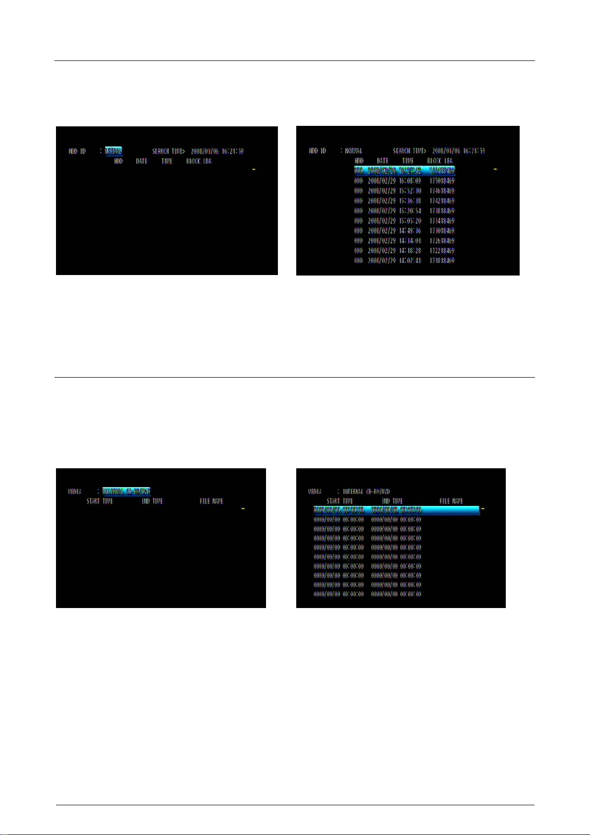
6.5 Block Search
Search the record data according to the data block in the HDD. If you fail to search by the other way or the
HDD is broken, you can use the BLOCK SEARCH for HDD raw data search.
Select the desired HDD ID, TIME, BLOCK and press the ENTER button, the search relausts will be shown.
Select the desired block and press ENTER to playback.
6.6 File Search
Search the record data according to the record file in the storage device. If user has more than two DVRs
which are the same model (with the same file format), you can save the record data of one DVR to external
storage device and play the data on the other DVRs.
Select the desired storage device and press the ENTER button, the search relausts will be shown. Select the
desired file and press ENTER to playback.
4/16-ch H.264 Digital Video Recorder
Page 54

6.7 Bookmark Search
Search the record data according to the BOOKMARK.
Enter the BOOKMARK SEARCH menu and press the ENTER button.
Select the desired BOOKMARK, and press the ENTER button to playback.
<How to make a BOOKMARK>
In the PLAYBACK mode:
Find the desired screen and then press the “PLAY/PAUSE” button to freeze the screen.
①
Press the “PTZ” button to make a bookmark.
②
6.8 Log File Search
DVR can store 20,000 records in the LOG file. When following important event occurs, DVR will generate a
record in the LOG file: Power on/off, Record on/off , Menu Change and Network Connection.
54
DVR-471 / DVR-1671 User Guide
Page 55

6.9 Search Button Information
SLOW (
Press this button to make the speed level which is slower than normal speed (X1) and displayed it at the
upper left side of screen as below; (If you press this button again, the playback speed will be changed in the
order of the below seven speed level).
① 1/2 - 2 times slower than normal playback speed
② 1/4 - 4 times slower than normal playback speed
③ 1/8 - 8 times slower than normal playback speed
④ 1/16 - 16 times slower than normal playback speed
⑤ 1/32 - 32 times slower than normal playback speed
⑥ 1/64 - 64 times slower than normal playback speed
⑦ 1/128 - 128 times slower than normal playback speed
PLAY / PAUSE (
Press this button to begin playback at normal speed (X1). Press this button again to pause the playback.
FAST (
Press this button to make faster the speed level which is higher than normal speed (X1) and displayed at the
upper left side of screen as below:
2 - 2 times faster than normal playback speed
①
4 - 4 times faster than normal playback speed
②
8 - 8 times faster than normal playback speed
③
16 - 16 times faster than normal playback speed
④
32 - 32 times faster than normal playback speed
⑤
64 - 64 times faster than normal playback speed
⑥
128 - 128 times faster than normal playback speed
⑦
(However much data may be recorded can be searched in 3 seconds)
DIRECTION (
Press this button to change direction to forward ( X ) or backward ( W ) in playback mode.
<A-B SECTION REPEATE PLAYBACK>
)
)
)
)
While playback, one may setup a specific period for respective playback.
1. Start playback
2. Press “SEQ” button to set up SECTION A (Starting Position), then the screen will show (A -).
3. Press “FREEZE” button to set up SECTION B (End Position), then the screen will show (A - B).
4. After setting section A-B, DVR starts playback repeating the setup.
Press “PIP” button and the section repetition playback will be canceled.
4/16-ch H.264 Digital Video Recorder
Page 56

7. COPY OPERATION and SETUP
To copy the DVR record data, you can enter the COPY menu through the main menu or press the COPY
button on the front panel.
7.1 Copy
Copy the record data from DVR internal HDD to external storage device.
7.1.1 Copy to USB Storage Device
First, please connect the USB devices (DVD Writer, HDD, Card Reader) to DVR and enter the COPY menu:
MEDIA: Select USB_FRONT
HDD ID: The HDD (HDD0, HDD1) which the record data saved. The default is NORMAL (search data in all
HDDs).
CHANNEL: Select to copy signal channel or all channels.
Select the desired MEDIA, HDD ID, CHANNEL, COPY START TIME, COPY END TIME and press the
ENTER button to start the copy.
56
DVR-471 / DVR-1671 User Guide
Page 57

NOTE:
- You can see a password input message. Please input the password by the numeric buttons or press
ECT button to cancel.
- You’ll need this password when opening the file in the network viewer.
- When the copy is in process, the copying status (ex. “COPY 30%”) will be displayed on the right side of
the monitor.
- Strong recommend you to format the USB storage device before use.
7.1.2 Copy to DVD±RW
Put the DVD±RW into DVD-ROM and enter the COPY menu:
Select the desired MEDIA (INTERNAL CD-RW/DVD), HDD ID, CHANNEL, COPY START TIME, COPY END
TIME and press the ENTER button to start the copy.
NOTE:
- You can see a password input message. Please input the password by the numeric buttons or press ECT
button to cancel.
- You’ll need this password when opening the file in the network viewer.
- When the copy is in process, the copying status (ex. “COPY 30%”) will be displayed on the right side of the
monitor.
4/16-ch H.264 Digital Video Recorder
Page 58

7.1.3 Stop Copy
If you press the COPY button during the COPY process, you’ll enter the COPY munu. Select the COPY item,
the following screen will appear, press “YES” to stop the COPY process.
7.1.4 Continue Copy
If the storage device full or error occurs during the COPY process, the “MEDIA FULL OR FAIL PRESS
[COPY]” message will be shown on the screen. Press COPY button, the following screen will appear:
CONTINUE COPY: After change a new media, the COPY process will be continued.
FORMAT MEDIA: Format the present storage device.
7.2 Copy Status
Review the status of the present COPY process.
COPY CUR TIME: Indicate current copying situation among the total copying data.
58
DVR-471 / DVR-1671 User Guide
Page 59

7.3 Format Media
To make sure the correctness of COPY, we strong recommend you to format the storage media before use.
NOTE: ALL DATA WILL BE REMOVED AFTER FORMAT.
Select the FORMAT MEDIA and move the cursor to MEDIA FORMAT, then press ENTER to format. The
message, “FORMATTING” will be displayed while formatting.
NOTE:
If you don’t connect any media, you will see the message, “Fail”.
The first time formatting the media will a take longer.
4/16-ch H.264 Digital Video Recorder
Page 60

8. NETWORK SETUP and OPERATION
8.1 Network Setup
• This DVR support dynamic IP and static IP.
• Remote view from Internet Explorer or DVR Viewer software. DVR Viewer provide plenty functions include
menu setup. IE support only simple viewing and playing.
• This DVR doesn’t support xDSL, there is a DYNAMIC IP SERVER, but no PPPoE protocol.
<Dynamic IP>
DHCP
DHCP is a protocol for assigning dynamic IP addresses to devices on a network., if you want to use dynamic
IP, please set the DHCP to “ON”. DVR will get IP/ SUBMASK/ DNS from DHCP server automatically.
Note:
When the function “DHCP ON” has been selected, please follow one out of the two steps below:
1. First connect the network line and then reboot the DVR.
2. Connect the network line (without rebooting the DVR), enter menu setup, and then select “save and exit”
to quit the menu setup.
<Static IP>
If you want to use static IP, please set the “DHCP” to “OFF”. Then just input the IP/ SUBMASK/ GATEWAY/
DNS and PORT (The default port is 5400) to finish network setup.
NOTE: Port setting on DVR and client viewer software must be matched.
DYNAMIC IP SERVER
After connecting to network, DVR will register its MAC address and IP address to the default DYNAMIC IP
SERVER. If you want to remote access the DVR through DVR Viewer, but unknown the IP address (ex.
Dynamic IP), you can connect to DVR with the MAC address, DYNAMIC IP SERVER will find out the correct
DVR IP address automatically.
NOTE: The IP address of DYNAMIC IP SERVER is a default value, we don’t recommend you to change it.
BACKUP IP SERVER
The function of the BACKUP IP SERVER is the same with DYNAMIC IP SERVER and just for backup. If the
DYNAMIC IP SERVER is out of service, the BACKUP IP SERVER will provide service instantly.
60
DVR-471 / DVR-1671 User Guide
Page 61

NETWORK FRAME
Select the desired value to select an image frame to be transported from DVR to network client viewer.
Note:
NETWORK FRAME is use for the transported image being influenced by Network speed.
- STILL: Use when the local network speed is too slow.
- MOTION: Use when the normal situation of network speed.
8.2 DVR-Viewer Installation
8.2.1 System Requirement
- CPU: Pentium 4 above
- O/S: Microsoft Windows 2000 / XP / VISTA
- RAM: 512MB RAM above
-Video Card: Super VGA 64M above
-Network card: 10/100/1000 network card for LAN operation
8.2.2 Network Environment
PC DVR
Minimum Requirement > 1Mbps > 0.5Mbps
Recommended
(16 Frames/Sec)
∗ The image transmission rate is depending on the login users of DVR.
> 3Mbps > 3Mbps
8.2.3 Installation Steps
Please insert the CD into CD-ROM drive and executes the Setup.exe program:
Click on “Next”.
4/16-ch H.264 Digital Video Recorder
Page 62

If you don’t need to change the default path, press “Install” to start installation.
Installation DVR-Viewer completed.
Click on “YES” to install the Roxio UDF Reader.
Click on “Next”.
62
DVR-471 / DVR-1671 User Guide
Page 63

Click on “Install”.
Click on “OK” and the installation completed.
Double click the following icon to start DVR-Viewer:
4/16-ch H.264 Digital Video Recorder
Page 64

8.3 DVR-Viewer Control Panel
1 2 3 4 5 6 7
9
8
10
11
1312
Items Description
1 DVR List: 「」Add/Modify/Delete the DVR connection list or connect to DVR.
2 DVR Search: To scan the available DVRs within a local network area.
3 HDD Search: To search the record data of DVR HDD connect to PC.
4 File Search: Search by record files (Copy from DVR or on PC).
5 Arrange Windows: To auto arrange the windows which open by DVR.
6 Viewer Option: DVR-Viewer setup.
7 Control panel switching buttons
8 Numeric buttons/ Channel selection buttons
DVR Controller: Just as the IR remote controller, mouse and the front buttons on the
DVR, the client software provides a controller to control the DVR remotely.
PTZ Controller
To enter the DVR Menu Setup.
To review the DVR status.
9
10 The DVR-Viewer version information.
11 Search buttons
12
To make a screen snapshot.
To copy the DVR images to PC.
Audio Input: After pressing the button, the audio sound from the PC will be sent to the DVR
through the microphone.
Audio Output: After pressing the button, PC user can hear the sound from the DVR (It is
only effective when the audio function has been enabled).
To switch the signal display mode and the multi display mode.
Enable/Disable the Auto Sequence mode and set the switching time.
13 Record and Playback buttons.
64
DVR-471 / DVR-1671 User Guide
Page 65

Press
button to switch to full screen mode.
4/16-ch H.264 Digital Video Recorder
Page 66

8.4 DVR-Viewer Operation
8.4.1 DVR-Viewer Software Password
When the DVR Viewer is run for the first time, it prompts for the administrator’s password. When you run the
software in the future, you’ll need this password. If you don’t want to set a password, please keep it empty.
Click on OK to start the program.
8.4.2 DVR List
Click on DVR List and input the password, the following window appears:
66
DVR-471 / DVR-1671 User Guide
Page 67

Add
○1 You can click on the DVR Search button (
) to auto scan the available DVRs in a local network area:
Press “Search” button to scan the DVRs, select the desired DVR and press “Add to List”. The selected DVR
will be added to the DVR List.
○2 Or input the DVR connection information directly, then click on “Add” to add a DVR.
Type: DVR connection type, select “Network” generally.
IP/Port/MAC: DVR IP address and connection port (The default is 5400). If you use dynamic IP, you can
connect to DVR through the IP Server. Check the “Use Ip Server” and then input MAC address.
Password: DVR password.
NOTE:
You must input the DVR password while remote connecting. If you login with the ADMIN password, you can
use all functions as in DVR, but if you login with other user’s password, you can’t modify the menu setup.
The maximum login users of DVR are 16, but just allow one ADMIN user to login at a time. When one user
The maximum user login is 16, but only one ADMIN user may login at a time. When one user login as
ADMIN and is operating the DVR, the second ADMIN user will be denied to login.
Change
Select the desired DVR in the DVR List, and then you can modify the DVR connection values. Press “Change”
to save the values.
Delete
Select the DVR you want to delete and click on “Delete” button.
Connect
Select the desired DVR and click on “Connect” to remote connect to DVR.
4/16-ch H.264 Digital Video Recorder
Page 68

8.4.3 HDD Search
Connect the DVR HDD to your PC, then you can search and playback the record data through HDD Search
function.
○1 Select the desired HDD, Channel and Video Mode.
○2 Press “OK”, the following window appears:
○3 Select the desired Channel and Search Time under the Time Search window, click on “Play” to playback.
68
DVR-471 / DVR-1671 User Guide
Page 69

8.4.4 File Search
Some users copy the DVR record data to DVD or USB storage device. Then use File Search function to
search and playback these data on PC.
Click on the File Search button, the following window appears:
○1 Select the desired search path through “Folder Select”.
○2 After selecting the desired Search Time, the results will be shown in above list. Select the desired file and
click on “Play” to playback.
○3 Click on “AVI Convert” button to convert the selected file to AVI format.
8.4.5 Arrange Windows
Arrange the windows opened by DVR-Viewer automatically.
* 1 window * 2 ~ 4 windows
*5 ~ 9 windows *10~16 windows
Double click on one window in multi display mode to extend to full screen.
4/16-ch H.264 Digital Video Recorder
Page 70

8.4.6 Viewer Option
Display:
- Channel Title: Show the Channel Title on the screen.
- Event: Show the event occured channel as Red on the screen.
- Date Time: Show the DVR date and time on the screen.
- Frame Rate: Show the Frame Rate on the screen.
Play Mode:
- Frame Mode: It will playback images in frame mode which is useful for recorded images in high frame rate.
This may occurs when moving artifact with recorded images in low frame rate.
- Field Mode: It playback images in field mode. This reduces the resolution, but is suitable for recorded
images in low frame rate.
Dynamic IP Server: Set the IP address of Dynamic IP Server and Backup IP Server.
Warning Sound: Check “Event” means the warning sound will be enabled while event occurring.
Event Mode: Check “Pop Up Window” to pop up the minimized main window when an event occurs.
WaterMark Check: To confirm the data correctness under LIVE mode or Playback mode.
File Split Mode: Under file search playback mode, click “MULTI” to display the order of the channel
previously setup in the file split mode.
User Management: To Add/Change/Delete the users and their rights of DVR-Viewer.
70
DVR-471 / DVR-1671 User Guide
Page 71

8.4.7 Display
a. Signal Display Mode: Click on the desired channel button to display as Signal Display Mode.
b. Multi Display Mode
Click on “MULTI” button to display as Multi Display Mode. Click on “MULTI” again to return to Signal Display
Mode.
c. Auto Sequence Mode
Click on “AUTO” button to display as Auto Sequence Mode, and you can also set the sequence time.
8.4.8 DVR Controller
Press “Controller” button, a control panel similar to DVR front panel will appears.
4/16-ch H.264 Digital Video Recorder
Page 72

8.4.9 PTZ Controller
Use the PTZ Controller to control PTZ camera through internet.
AF: AutoFocus Adjustment
Zoom: PTZ camera Zoom in/Zoom out control
Focus: PTZ camera Focus adjustment
Preset
You can preset the desired PTZ camera position and save as a Preset Point. DVR provides 16 Preset Points
for your setting. Adjust all PTZ camera settings and then click on any of the 16 buttons in Set line to save as
Preset Point.
You can also apply the Preset Point to any PTZ camera. Select the desired channel and click on any of the 16
buttons in Move line, then the PTZ camera will move to the preset position.
8.4.10 Setup
Click on “SETUP” button and input the DVR ADMIN password, you can enter to the DVR menu setup.
72
DVR-471 / DVR-1671 User Guide
Page 73

Save To File: Save the DVR menu settings to a file.
Read From File: Read the DVR menu settings from a file.
Load From DVR: Load the real time settings from DVR to PC.
Update to DVR: Update the menu settings in PC to DVR.
QUICK SETUP
Please refer to QUICK SETUP of user’s manual.
SCREEN
You can generate a channel title as a Bitmap file and load to DVR in the SCREEN-TITLE page.
1. Input the desired words in below box, adjust the Font type and position, then click on “Make Bitmap”
button to generate a Bitmap file.
2. Click on “Download” button to load the Bitmap file to DVR. Change the Channel Title Mode to BITMAP,
then you can see the new title in Bitmap mode on DVR.
For the rest settings please refer to SCREEN of user’s manual.
RECORD
To set the Schedule Record, please click on an hour block and then click “SCHEDULE RECORD ON/OFF”.
An hour block when enabled becomes Green. Move the cursor to any time point on the vertical ALL roll, then
click on “SCHEDULE RECORD ON/OFF” to cancel record schedule.
4/16-ch H.264 Digital Video Recorder
Page 74

Turn the wheel scroll of the mouse on specific hour block to change the Record Program (0~9); double click
the left key of mouse, the following window appears:
For the rest settings, please refer to RECORD SETUP of user’s manual.
EVENT
Please refer to EVENT SETUP of user’s manual.
SYSTEM
Please refer to SYSTEM of user’s manual.
74
DVR-471 / DVR-1671 User Guide
Page 75

LINK
Please refer to NETWORK SETUP of user’s manual.
DOWNLOAD
Download the Firmware from DVR to PC.
8.4.11 Status
Click on “STATUS” button to review the System/Record/Network/Bit Rate status.
4/16-ch H.264 Digital Video Recorder
Page 76

8.4.12 Print
Click on the “PRINT” button to make a screen snapshot and save as a file. The size of snapshot is depend on
the Record Image Size (D1、Half-D1、CIF).
8.4.13 Copy
Copy the DVR images to PC.
Select the desired HDD, Time and channel, click on “Copy” button to start copy. The Copying stutus will be
shown as below. Click on “OK” button after the copy finished, the file will be saved in C:\Program Files\DVR
\DVR-Viewer\Copy automatically.
76
DVR-471 / DVR-1671 User Guide
Page 77

8.4.14 Search
Please refer to Search Operation and Setup of user’s manual.
8.4.15 Record and Playback Control Buttons
1 Fast Backward (2X~128X)
2 Playback Backward Slowly (1/2X~1/128X)
3 Playback Backward
4 Pause
5 Playback Forward
6 Playback Forward Slowly (1/2X~1/128X)
7 Fast Forward (2X~128X)
Record
Click on Record button to record the LIVE images on PC as a file. The file will be saved in C:\Program
Files\DVR \DVR-Viewer\Save automatically.
4/16-ch H.264 Digital Video Recorder
Page 78

9. ADDITIONAL FUNCTION OPERATION and SETUP
9.1 E-Mail
Enter the LINK -> E-mail menu
SEND E-MAIL
Select from “ON”, “OFF”, The default is “OFF”. When SEND E-MAIL set to “ON”, DVR will send a e-mail when
an event happened.
SMTP SERVER
Move the cursor to SMTP SERVER and press ENTER button to input the IP address.
①
Select the character using the S, T, W, X buttons and then press the ENTER button.
②
To exit this CHARACTER TABLE screen, press the ESC button.
③
DVR E-MAIL ADDR
To set the E-Mail Receiver address when event occurs.
Move the cursor to DVR E-MAIL ADDR and press ENTER button:
①
Select the character using the S, T, W, X buttons and then press the ENTER button.
②
To exit this CHARACTER TABLE screen, press the ESC button.
③
78
DVR-471 / DVR-1671 User Guide
Page 79

USER ID
Move the cursor to USER ID and press ENTER button:
①
Select the character using the S, T, W, X buttons and then press the ENTER button.
②
To exit this CHARACTER TABLE screen, press the ESC button.
③
PASSWORD
Move the cursor to PASSWORD and press ENTER button:
①
Select the character using the S, T, W, X buttons and then press the ENTER button.
②
To exit this CHARACTER TABLE screen, press the ESC button.
③
9.2 Record Limit
In this function, you can choose a certain period of time for recording. After certain period of time, the data of
recording will be deleted automatically. So, DVR remain the data of certain period of time only.
For example, if the setting of record limit is 1 day, the recording data in the HDD will always have only one day.
While the latest hour is writing in the storage, the oldest hour will be deleted. The default value of this option is
off.
4/16-ch H.264 Digital Video Recorder
Page 80

9.3 Connect to DVR through IE
9.3.1 Download Web Interface via Internet
Step1. Connect to this web site (IP address: 211.174.251.155) and the following interface will be shown:
Step2. Input the IP address of DVR and then click “Connect”.
Step3. Type the password to access the DVR (Default Password: 11111111)
80
DVR-471 / DVR-1671 User Guide
Page 81

Step4. The LIVE image will be displayed.
Note1: When first time connecting to this web site, ActiveX component is downloaded and installed
automatically. It will take a few minutes. If the Internet Explorer does not allow this installation, please
adjust the security option of the browser.
Note2: If the DVR cannot be connected, please delete the file “XViewer.dat” on your desktop and try again.
9.3.2 Directly Use Web Interface
Download the “XViewer” from user’s manual CD.
Unzip the XViewer.zip and then double click the XViewer.htm for connecting through IE browser.
Note: The operation and web UI is the same with the one which downloaded through internet.
4/16-ch H.264 Digital Video Recorder
Page 82

Appendix 1 --- TROUBLE SHOOTING
Q: What brand of hard disk does the DVR support?
A: DVR supports Western Digital and Seagate hard disks. The maximum capacity is 1
terabyte for each device.
Q: What type of DVD disks is competitble?
A: DVD-RW (MITSUBISHI 2X-4X, Verbatim 6X, VIO 4X); DVD+RW (MITSUBISHI 1X-4X,
Verbatim 6X, PHILIPS 1-4X).
Q: Why isn’t PS/2 mouse working?
A: User needs to use the mouse together with the wheel. Some functions need this third
button.
Q: Why is my VGA monitor showing the message "out of range"?
A: The composite and VGA monitor cannot be used at the same time. It must be selected
before starting the DVR. Please refer to the page 13 to find how to change the monitor
type.
82
DVR-471 / DVR-1671 User Guide
Page 83

EC Declaration of Conformity
For the following equipment:
*Type of Product :
4-ch H.264 Digital Video Recorder
*Model Number : DVR-471
* Produced by:
Manufacturer‘s Name : Planet Technology Corp.
Manufacturer‘s Address : 11F, No. 96, Min Chuan Road, Hsin Tien,
Taipei, Taiwan, R.O.C.
is herewith confirmed to comply with the requirements set out in the Council Directive on the
Approximation of the Laws of the Member States relating to Electromagnetic Compatibility Directive on
(89/336/EEC).
For the evaluation regarding the EMC, the following standards were applied:
Emissions
Immunity
EN 55022:2006 (Class A) EN 50130-4:1995+A1/1998+A2/2003
EN 61000-3-2:2006 IEC 61000-4-2:2001
EN 61000-3-3:1995/A2:2005
IEC 61000-4-3:2006
IEC 61000-4-4:2004
IEC 61000-4-5:2005
IEC 61000-4-6:2006
IEC 61000-4-11:2004
Responsible for marking this declarati o n i f the:
⌧ Manufacturer Authorized representative established within the EU
Authorized representative established within the EU (if applicable):
Company Name: Planet Technology Corp.
Company Address: 11F, No.96, Min Chuan Road, Hsin Tien, Taipei, Taiwan, R.O.C
Person responsible for making this declaration
Name, Surname John Sung
Position / Title : Product Manager
Taiwan
15, Aug., 2008 _________________
Place Date Legal Signature
PLANET TECHNOLOGY CORPORATION
e-mail: sales@planet.com.tw http://www.planet.com.tw
11F, No. 96, Min Chuan Road, Hsin Tien, Taipei, Taiwan, R.O.C. Tel:886-2-2219-9518 Fax:886-2-2219-9528
Page 84

EC Declaration of Conformity
For the following equipment:
*Type of Product :
16-ch H.264 Digital Video Re corder
*Model Number : DVR-1671
* Produced by:
Manufacturer‘s Name : Planet Technology Corp.
Manufacturer‘s Address : 11F, No. 96, Min Chuan Road, Hsin Tien,
Taipei, Taiwan, R.O.C.
is herewith confirmed to comply with the requirements set out in the Council Directive on the
Approximation of the Laws of the Member States relating to Electromagnetic Compatibility Directive on
(89/336/EEC).
For the evaluation regarding the EMC, the following standards were applied:
Emissions
Immunity
EN 55022:2006 (Class A) EN 50130-4:1995+A1/1998+A2/2003
EN 61000-3-2:2006 IEC 61000-4-2:2001
EN 61000-3-3:1995/A2:2005
IEC 61000-4-3:2006
IEC 61000-4-4:2004
IEC 61000-4-5:2005
IEC 61000-4-6:2006
IEC 61000-4-11:2004
Responsible for marking this declarati o n i f the:
⌧ Manufacturer Authorized representative established within the EU
Authorized representative established within the EU (if applicable):
Company Name: Planet Technology Corp.
Company Address: 11F, No.96, Min Chuan Road, Hsin Tien, Taipei, Taiwan, R.O.C
Person responsible for making this declaration
Name, Surname John Sung
Position / Title : Product Manager
Taiwan
15, Aug., 2008 _________________
Place Date Legal Signature
PLANET TECHNOLOGY CORPORATION
e-mail: sales@planet.com.tw http://www.planet.com.tw
11F, No. 96, Min Chuan Road, Hsin Tien, Taipei, Taiwan, R.O.C. Tel:886-2-2219-9518 Fax:886-2-2219-9528
 Loading...