

Page 1

4-CH MPEG-4 Digital Video Recorder
DVR-460
User’ s Manual
Page 2

Copyright
Copyright (C) 2008 PLANET Technology Corp. All rights reserved.
The products and programs described in this User’s Manual are licensed products of PLANET
Technology, This User’s Manual contains proprietary information protected by copyright, and this
User’s Manual and all accompanying hardware, software, and documentation are copyrighted.
No part of this User’s Manual may be copied, photocopied, reproduced, translated, or reduced to
any electronic medium or machine-readable form by any means by electronic or mechanical.
Including photocopying, recording, or information storage and retrieval systems, for any purpose
other than the purchaser's personal use, and without the prior express written permission of
PLANET Technology.
Disclaimer
PLANET Technology does not warrant that the hardware will work properly in all environments and
applications, and makes no warranty and representation, either implied or expressed, with respect
to the quality, performance, merchantability, or fitness for a particular purpose.
PLANET has made every effort to ensure that this User’s Manual is accurate; PLANET disclaims
liability for any inaccuracies or omissions that may have occurred.
Information in this User’s Manual is subject to change without notice and does not represent a
commitment on the part of PLANET. PLANET assumes no responsibility for any inaccuracies that
may be contained in this User’s Manual. PLANET makes no commitment to update or keep current
the information in this User’s Manual, and reserves the right to make improvements to this User’s
Manual and/or to the products described in this User’s Manual, at any time without notice.
If you find information in this manual that is incorrect, misleading, or incomplete, we would
appreciate your comments and suggestions.
FCC Warning
This equipment has been tested and found to comply with the limits for a Class A digital device,
pursuant to Part 15 of the FCC Rules. These limits are designed to provide reasonable protection
against harmful interference when the equipment is operated in a commercial environment. This
equipment generates, uses, and can radiate radio frequency energy and, if not installed and used in
accordance with the Instruction manual, may cause harmful interference to radio communications.
Operation of this equipment in a residential area is likely to cause harmful interference in which
case the user will be required to correct the interference at his own expense.
CE mark Warning
The is a class A device, In a domestic environment, this product may cause radio interference, in
which case the user may be required to take adequate measures.
Trademarks
The PLANET logo is a trademark of PLANET Technology. This documentation may refer to
numerous hardware and software products by their trade names. In most, if not all cases, these
designations are claimed as trademarks or registered trademarks by their respective companies.
WEEE Warning
To avoid the potential effects on the environment and human health as a result of
the presence of hazardous substances in electrical and electronic equipment, end
users of electrical and electronic equipment should understand the meaning of the
crossed-out wheeled bin symbol. Do not dispose of WEEE as unsorted municipal
waste and have to collect such WEEE separately.
Revision
User’s Manual for PLANET 4-CH MPEG-4 Digital Video Recorder
Model: DVR-460
Rev: 2.0
Part No.: EM-DVR460_v2
2
DVR-460 User Guide
Page 3

Table of Contents
1. OVERVIEW ................................................................................................................... 5
1.1 Product features...................................................................................................... 5
1.2 Product Specifications............................................................................................. 6
1.3 Package Content..................................................................................................... 7
2. FRONT AND REAR PANELS ....................................................................................... 8
2.1 Front Panel ............................................................................................................. 8
2.2 Rear Panel ............................................................................................................ 10
3. CONNECTION AND SETUP....................................................................................... 12
3.1 HDD Installation .................................................................................................... 12
3.2 Camera Connection .............................................................................................. 13
3.2.1 Normal camera connection....................................................................... 13
3.2.2 PTZ camera connection ........................................................................... 14
3.3 External Device Connections ................................................................................ 15
3.3.1 IR Transmitter ........................................................................................... 15
3.4 Power Setup ......................................................................................................... 15
3.5 Date and Time Setting........................................................................................... 15
3.6 Password Setting .................................................................................................. 16
4. BASIC OPERATION.................................................................................................... 17
4.1 Live Page .............................................................................................................. 17
4.2 Recording.............................................................................................................. 17
4.3 Playback ............................................................................................................... 17
4.4 Key Lock and Unlock ............................................................................................ 19
4.5 Firmware / Multi-language OSD Upgrade ............................................................. 19
4.6 Search................................................................................................................... 19
4.7 Audio Backup and Playback.................................................................................. 20
5. MENU CONFIGURATION ........................................................................................... 21
5.1 Menu List .............................................................................................................. 21
6. QUICK START MENU................................................................................................. 23
6.1 Quick Search ........................................................................................................ 23
6.2 Record .................................................................................................................. 24
6.3 Timer..................................................................................................................... 25
6.4 Date ...................................................................................................................... 25
7. ADV ANCED MENU ..................................................................................................... 27
7.1 Camera ................................................................................................................. 27
7.2 Detection............................................................................................................... 28
7.3 Remote ................................................................................................................. 30
7.4 Display .................................................................................................................. 31
7.5 Alert....................................................................................................................... 32
7.6 System .................................................................................................................. 33
7.7 Network................................................................................................................. 35
7.8 Backup .................................................................................................................. 38
4-CH MPEG-4 Digital Video Recorder
3
Page 4

7.9 HDD Info ............................................................................................................... 40
7.10 Event Log............................................................................................................ 41
8. REMOTE OPERATION ............................................................................................... 42
8.1 Supplied Licensed AP Software ............................................................................ 42
8.1.1 Installation & Network Connection............................................................ 42
8.1.2 General AP Operation............................................................................... 43
Record ............................................................................................................43
Playback .........................................................................................................44
Network Backup..............................................................................................45
8.1.3 AP Control Panel ...................................................................................... 46
8.1.4 AP Functions ............................................................................................ 47
Image Display .................................................................................................47
Address Book .................................................................................................48
Miscellaneous Control ....................................................................................50
DVR Control....................................................................................................73
8.2 IE Web Browser .................................................................................................... 74
8.3 Quick Time Player ................................................................................................. 76
Appendix 1 --- PIN CONFIGURATION........................................................................... 78
Appendix 2 --- COMPATIBLE USB DRIVE FLASH BRAND.......................................... 79
Appendix 3 --- COMPATIBLE HDD BRAND.................................................................. 80
Appendix 4 --- TROUBLESHOOTING............................................................................ 81
Appendix 5 --- DEFAULT VALUE................................................................................... 82
4
DVR-460 User Guide
Page 5

1. OVERVIEW
1.1 Product features
MPEG4 Technology
‧ MPEG-4 compression format providing crystal clear images with real time performance
‧ MPEG-4 web transmitting for faster transmission and clearer images via network
Multiplex Operation
‧ Allows live display, record, playback, backup, and network operations at the same time
Free Upgrade to Advanced Functions
‧ Allows you to upgrade DVR functions without any charges
Backup Device
‧ Network
‧ USB flash drive
Remote Surveillance
‧ Supports remote surveillance up to 20 users simultaneously with licensed software AP,
IE browser & Mozilla Firefox browser
Intelligent Motion Trigger Recording
‧ With the advanced functions of motion detection, scheduled motion detection
recording (4 different adjustable factors for motion detection sensitivity) and quick
search, customized security environments are achieved
‧ Alarm trigger recording will send alerts with images to designated e-mails and the FTP
address
‧ Supports pre-alarm recording (2MB)
Covert Recording
‧ Blank screen replaces live displays to achieve covert recording
Audio Support
‧ Supports 1 audio-in, 1 audio-out to record sounds
General
‧ Supports multi-language OSD
‧ System auto recovery after power failure
‧ Supports PTZ camera operations through RS485 signals
‧ Supports manual / timer / motion / alarm / network remote recording
‧ Supports TCP/IP, PPPoE, DHCP and DDNS network connection
‧ Supports IR remote control
‧ Supports SATA HDD
4-CH MPEG-4 Digital Video Recorder
5
Page 6

1.2 Product Specifications
Model Name DVR-460
Video System NTSC / PAL (switchable)
Video Compression Format MPEG-4
Video Input 4 Channels (Composite video signal 1 Vp-p 75Ω BNC)
Video Loop Out 4 Channels (Composite video signal 1 Vp-p 75Ω BNC)
Video Output
Maximum Recording Rate
Adjustable Recording Speed
Multi-language OSD Yes
Image Quality Setting Best, High, Normal and Basic
Hard Disk Storage 1x SATA HDD (Supports over 1000GB HDD capacity)
HDD Quick Cleaning Quick clean up the “index system” of the recorded files. 1TB under 2 seconds
Recording Mode Manual / Timer / Motion / Alarm / Remote
Refresh Rate 120 IPS for NTSC / 100 IPS for PAL
Audio I/O 1x audio input, 1x audio output (Mono)
Motion Detection Area 16×12 grids per camera for all channels
Motion Detection Sensitivity 4 adjustable variables with precise calculation for motion detection
Pre-alarm Recording Yes (8MB)
USB Interface Supports USB1.1/2.0 flash drive
Backup Device Network and USB flash drive
Web Transmitting
Compression Format
Ethernet 10/100 Base-TX. Supports remote control and live view via Ethernet.
Web Interface Supports licensed software AP, IE browser & Mozilla Firefox browser
Remote Alarm Notification E-mail images, and upload images to FTP site’s specific account
Network Protocol Supports TCP/IP, PPPoE, DHCP and DDNS functions
PTZ control Supports PELCO-D protocol
IR Remote Controller Yes
Dwell Time
(Sequential Channel Switch)
Alarm I/O 4x inputs, 1x output
Digital Zoom 2X digital zoom (live mode)
Key Lock Yes
Video Loss Detection Yes
Camera Title Supports up to 6 letters
Video Adjustable Hue / Color / Contrast / Brightness
Date Display Format YY/MM/DD, DD/MM/YY, MM/DD/YY, and Off
System Recovery System auto recovery after power failure
Power Source DC 19V
Power Consumption <42 W
Operating Temperature 10°C ~ 40°C (50°F ~104°F)
Dimensions (mm) 345(W) x 68.3(H) x 225(D)
Main Monitor Output / Call Monitor Output
(Composite video signal 1 Vp-p 75Ω BNC)
Frame: 720×480 pixels with 30 IPS <NT> / 720×576 pixels with 25 IPS <PA>
CIF: 352×240 pixels with 120 IPS <NT> / 352×288 pixels with 100 IPS <PA>
Frame: 30, 15, 7, 3 IPS <NT> / 25, 12, 6, 3 IPS <PA>
CIF: 120, 60, 30, 15 IPS <NT> / 100, 50, 25, 12 IPS <PA>
MPEG-4
Programmable with adjustable dwell time
6
DVR-460 User Guide
Page 7

1.3 Package Content
DVR-460
Power adapter
Power cord
Quick installation guide
User’s manual CD
DSUB PIN connector
Flat cable clamp
Remote controller
IR receiver
Screws
Note:
If any of above items are missing or damaged, please contact your local dealer for support.
4-CH MPEG-4 Digital Video Recorder
7
Page 8

2. FRONT AND REAR PANELS
2.1 Front Panel
1) LED Indication
The following LEDs will be on when:
HDD: HDD is reading or recording
HDD Full: HDD is full.
ALARM: Once the alarm is triggered
TIMER: When timer recording is turned on
PLAY: Under playing status
REC: Under recording status
2) MENU
Press this button to enter / exit the DVR menu mode.
In the sub-layer of the DVR menu, press this button to confirm the settings and go back
to the upper layer.
3) ENTER
Confirm the password entering.
4) REC
Press this button to activate manual recording.
5) LIST (Event List Search)
To quick search the recorded files by event list, press this button to show all types of the
event lists.
Select one of the event list and press “ENTER” button to playback the selected file.
MANUAL: List the information of the manual-recorded files. The DVR will save one
recorded file once any recording setting is changed
SYSTEM: List the information of the system-recorded files. The DVR system will save
one recorded file every one hour.
MOTION: List the information of the motion-trigger-recorded files.
TIMER: List the information of the timer-recorded files.
6) SLOW
Under the playback mode,
Press “SLOW” button to get 1/2X speed playback.
7) ZOOM
In the live mode of the DVR, press this button to enlarge the image of the selected
channel.
8) / -
Press “ ” button to show the 4 channel display modes.
Press “-” button to change the setting in the menu.
8
DVR-460 User Guide
Page 9

9) SEQ /+
Press “SEQ” button to activate the call monitor function, and press again to quit.
Press ”+” button to change the setting in the menu.
10) Power
Press this button long enough to turn on/off your DVR.
Note:
Under the recording mode, please stop recording before turning off your DVR.
11) 1 / 2 / 3 / 4
Press one of these buttons to show the channel display of CH1 ~ CH4 on the monitor.
12)
Press this button to play the recorded video.
13) Pause / Stop / Rew / FF
Under the playback mode:
Press one of these button to pause / stop / rewind / fast-forward the playback file.
14) Up / Down / Left / Right
Press one of these direction buttons to move the cursor up/down/left/right.
Under the DVR menu mode, these direction buttons can use for the following operation:
Up / Down: Make the selection / Change the settings
Left / Right: Make the selection
SLOW
ZOOM
15)
AUDIO
(Audio)
Press these two buttons at the same time to select live or playback sounds of the audio
channels.
SEQ.
16)
P.T.Z
(PTZ)
Press these two buttons at the same time to enter / exit the PTZ control mode.
In the PTZ control mode → Zoom in: Press "+" button ; Zoom out: Press "-" button
Adjust PTZ angle: Press direction buttons to turn up/down/left/right
17) “MENU” + “ENTER” (Key lock)
Press these two buttons at the same time to lock keys on the DVR front panel.
4-CH MPEG-4 Digital Video Recorder
9
Page 10

2.2 Rear Panel
1) 75Ω / HI-IMPEDANCE
When using LOOP function, please switch to HI-IMPEDANCE. Otherwise, please
switch to 75Ω.
2) LOOP / INPUT (For channel 1~4)
LOOP: Video output connector.
INPUT: Connect to video sources, such as cameras.
Note:
If you want to playback the video with audio, please connect an audio camera to Input 1 on the
DVR rear panel.
3) MONITOR
Connect to MAIN monitor.
4) CALL
Connect to CALL monitor to show the channel display one by one.
When any alarm is triggered, CALL monitor will show the image of the triggered channel
for a period of time.
5) AUDIO IN
Connect to audio sources, such as cameras equipped with the audio function.
When users start recording, the audio input will also be recorded.
6) AUDIO OUT
Connect to a monitor or speaker with 1 mono audio output.
7) USB
To quickly backup or upgrade firmware/OSD, you can insert a compatible USB flash
drive into this USB port. Before using the USB flash drive, please use your PC to format
the USB flash drive as “FAT32” first.
For the list of compatible USB flash drivers, please refer to “Appendix 2 COMPATIBLE
USB FLASH DRIVE BRAND”
8) IR
Connect the IR receiver for remote control.
9) EXTERNAL I/O
Insert the supplied 15PIN DSUB to this port for connecting external devices (external
alarm, PTZ camera, etc).
For detailed I/O PIN configuration, please refer to “Appendix 1 PIN CONFIGURATION”.
10) LAN
Connect to Internet by LAN cable.
11) LINK ACT.
When your DVR is connected to the Internet, this LED will be on.
10
DVR-460 User Guide
Page 11

12) DC 19V
Connect to the supplied adapter.
4-CH MPEG-4 Digital Video Recorder
11
Page 12
3. CONNECTION AND SETUP
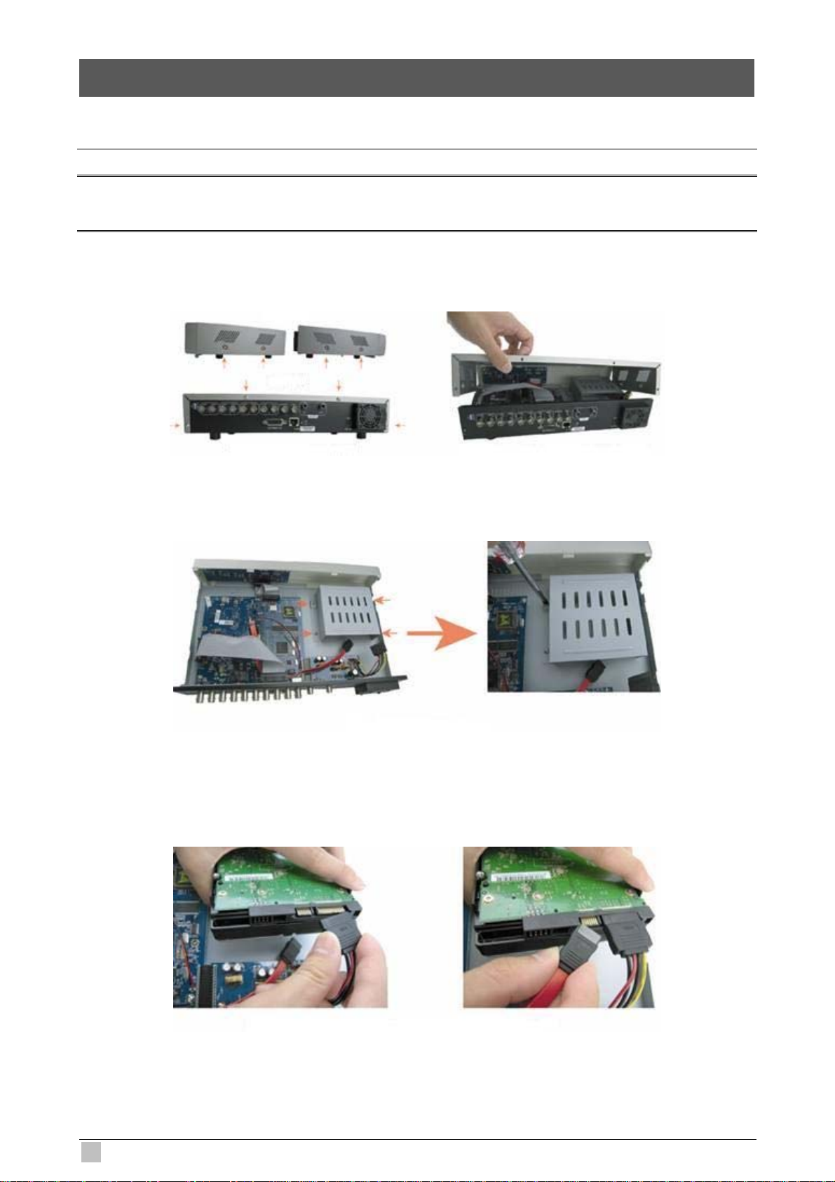
3.1 HDD Installation
Note:
The HDD must be installed before the DVR is turned on.
Step1: Loose the screws on the upper cover and open the upper cover of the DVR.
Step2: Remove the HDD bracket.
Step3: Get a compatible SATA HDD, and connect it to the power connector and data bus
connector (make sure to align the HDD precisely for pin connection).
12
DVR-460 User Guide
Page 13

Step4: Screw the HDD onto the HDD bracket (Two screws for each side), and then screw
the HDD bracket back to the DVR base.
Step5: Close the upper cover of the DVR, and fasten all the screws you loosened in Step 1.
3.2 Camera Connection
The cameras must be connected and power-supplied BEFORE the DVR is turned on. The
DVR will automatically detect the video system of the connected camera(s) (NTSC / PAL),
and switch itself to the correct system.
Note:
1. For detailed DVR video input / output ports, please refer to “2.2 Rear Panel”.
2. If you want to make a video backup with audio, please connect audio camera to the CH1 which
supports the audio function.
3.2.1 Normal camera connection
1) Power connection
Connect the camera with indicated power supply.
2) Video cable connection
Connect the camera video output to the DVR video input port with a coaxial cable or
RCA line with BNC connector.
3) Camera Setup MONITOR
For detailed camera title, ID, protocol and baud rate setup, please refer to “REMOTE”.
4-CH MPEG-4 Digital Video Recorder
13
Page 14
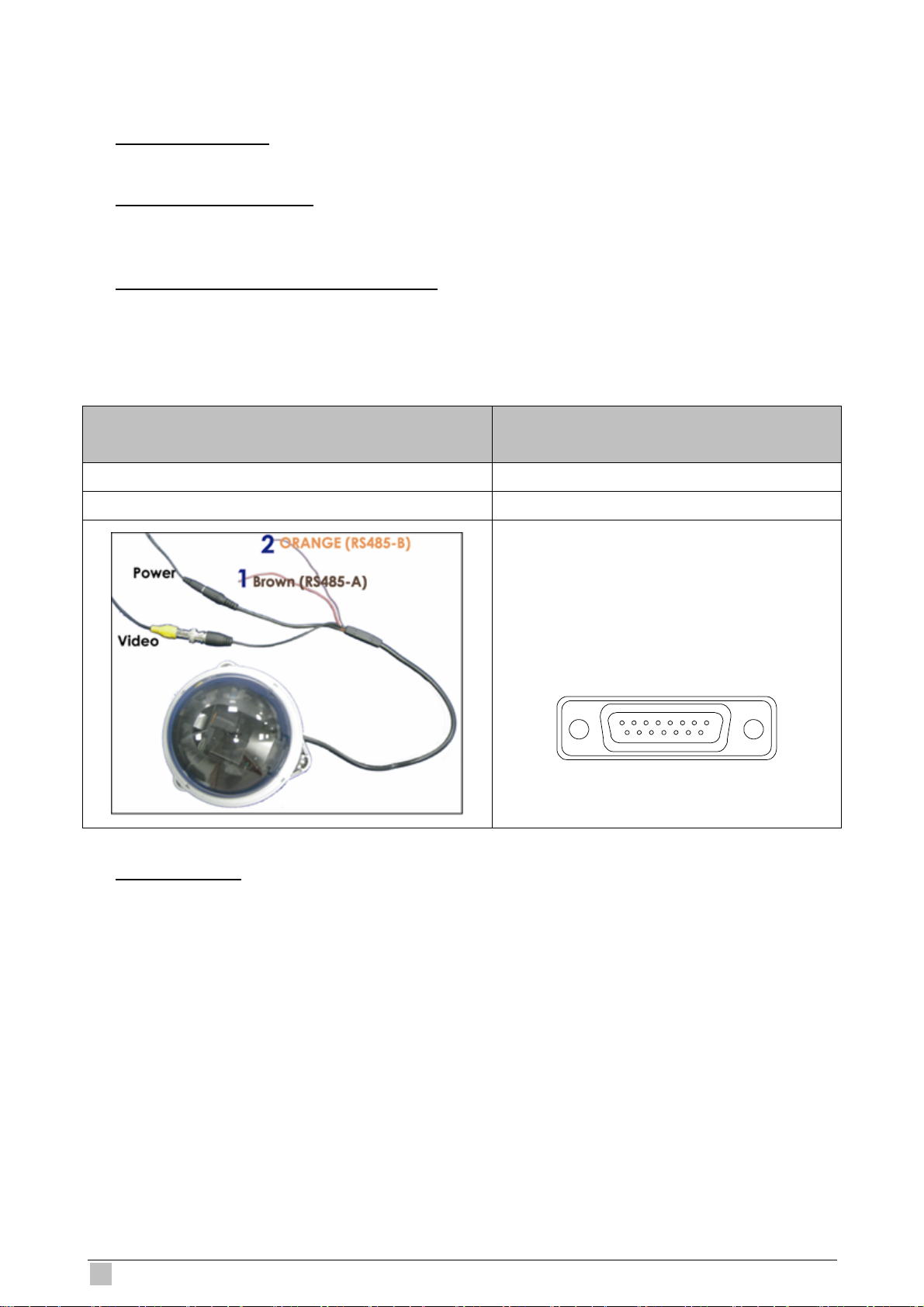
3.2.2 PTZ camera connection
1) Power connection:
Connect the PTZ camera with indicated power supply.
2) Video cable connection:
Connect the PTZ camera video output to the DVR video input with a coaxial cable / RCA
line and BNC connector.
3) RS485-A & RS485-B wires connection:
Solder the RS485-A (brown) and RS485-B (orange) wires of the PTZ camera to the
corresponding pins on the solder side of the 15 PIN D-Sub connector (see the figure
below). To protect the naked wires, use the insulation tape to cover on the twisted wires.
PTZ Camera –
RS485-A and RS485-B wires of the PTZ camera
RS485-A: Brown wire RS485-A: PIN 11
RS485-B: Orange wire RS485-B: PIN 10
For 4CH DVR –
15 PIN D-Sub Connector
Solder Side of
15-pin D-Sub connector
RS485-A: PIN11; RS485-B: PIN10
16 17
1
2345678
912131415
1011
4) Camera Setup:
For detailed camera title, ID, protocol and baud rate setup, please refer to “7.3
REMOTE”.
14
DVR-460 User Guide
Page 15

3.3 External Device Connections
3.3.1 IR Transmitter
Please connect the IR receiver line to the IR port on the DVR rear panel. And make sure the
IR function is activated in the DVR menu (The default setting is on). Please refer to the
following figure as an example.
3.4 Power Setup
This device should be operated only with the type of power source indicated on the
manufacturer’s label. Connect the indicated AC power cord to the power adapter, and plug
into an electrical outlet. The power LED “ ” will be on as green. It takes approximately 10
to 15 seconds to boot the system.
3.5 Date and Time Setting
Before operating your DVR, please set the date and time on your DVR first.
Press the “MENU” button and enter the password to go to the menu list. The default admin
password is 0000. Move the cursor to “DATE” and you can set the date / time / daylight
saving in the “DATE” menu list.
4-CH MPEG-4 Digital Video Recorder
15
Page 16

3.6 Password Setting
Press the “MENU” button and enter the password to go to the menu list. Then, move the
cursor to “ADVANCE” to enter the advanced setting menu.
In the “ADVANCE” menu, move the cursor to “SYSTEM”. Select “PASSWORD” and press
the “ENTER” button to enter the submenu to set the password (four digits). The default
admin password is 0000.
ADVANCE SYSTEM
CAMERA SERIAL TYPE RS485
DETECTION BAUDRATE 2400
REMOTE HOST ID 0
DISPLAY
ALERT RESET DEFAULT RESET
SYSTEM
NETWORK UPGRADE START
BACKUP AUTO KEYLOCK NEVER
HDD INFO LANGUAGE ENGLISH
VIDEO FORMAT NTSC
VERSION 1160-1012-1021-1014-M3-6C1B
PASSWORD XXXX
CLEAR HDD HDD-MASTER-1
16
DVR-460 User Guide
Page 17
4. BASIC OPERATION
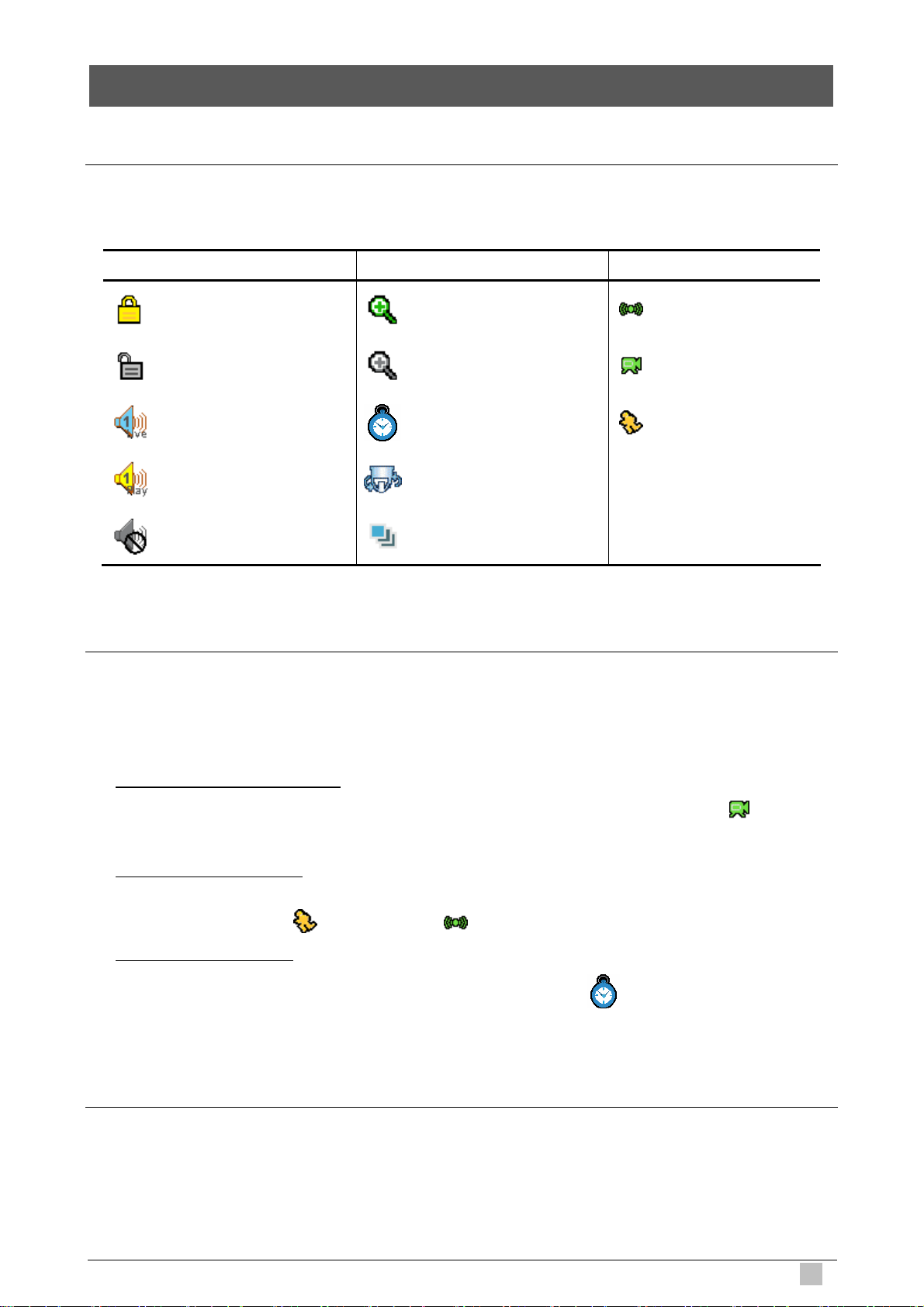
4.1 Live Page
In this live page of the DVR, you can see the following icons:
Icon Function Icon Function Icon Function
Key lock
Key unlock
Live audio channel
Playback audio channel
Audio channel unselected
Digital zoom mode Alarm
Digital zoom unselected Recording
Timer recording Motion
PTZ control mode
Full screen sequence mode
4.2 Recording
When the recording and the pre-alarm function are activated, this device will overwrite 8GB
data from the oldest for continuous recording without notice.
1) Continuous Recording Icon
When the DVR is properly connected with camera, you can see the icon “ ”
(recording) on the monitor.
2) Motion Recording Icon
When the motion / alarm detection is activated, once motion or external alarm happens,
you will see the icon “ ” (motion) and “ ” (alarm) on the monitor.
3) Timer Recording Icon
When the timer record is activated, you will see the icon “ ” (timer) on the monitor
4.3 Playback
Press the “PLAY” button on the DVR control panel, and the device will playback the latest
recorded video.
4-CH MPEG-4 Digital Video Recorder
17
Page 18

Note:
There must be at least 8192 images of recorded data for playback to work properly. If not, the
device will stop playback. For example, if the IPS is set to 30, the recording time should be at least
273 seconds (8192 images / 30 IPS) for the playback to work properly.
1) Fast Forward / Fast Rewind
You can increase the speed for fast forward and rewind on this device. In the playback
mode:
Press “FF“ once to get 4X speed forward and press twice to get 8X speed, etc. And the
maximum speed is 32X.
Press “REW“ once to get 4X speed rewind and press twice to get 8X speed, etc. And
the maximum speed is 32X.
Note:
During playback, the image size of the recording (CIF) will be shown on the screen.
2) Pause / Image Jog
Press “PAUSE” button to pause the playback.
In the pause mode:
Press “►” button once to get one frame forward.
Press “◄” button once to get one frame rewind.
3) Stop
Pressing “STOP” button under playback mode, the screen of this device will return to
live monitoring mode.
4) Slow Playback
Press “SLOW” button to get 1/4X speed playback and press twice to get 1/8X speed
playback.
5) Audio Playback
SLOW
ZOOM
Use these two buttons
AUDIO
to select the live or playback sound of the audio
channels.
Live audio of the 1st audio channel Playback audio of the 1st audio channel
ote: N
If you want to make a video backup with audio, please connect your camera which supports the
audio function to CH1 first.
18
DVR-460 User Guide
Page 19

4.4 Key Lock and Unlock
1) Key Lock On:
Press “MENU”
+ “ENTER” buttons at the same time on the DVR control panel to lock
keys.
Or set
the time-out after which the key lock function is activated (Never / 10 SEC / 30
SEC / 60 SEC).
2)
Key Lock Off:
Enter the DVR password to exit “Key Lock” mode.
4.5 Firmware / Multi-language OSD Upgrade
1) Use USB flash drive to upgrade firmware or OSD:
Step 1. Format the USB memory device as FAT32 f
Step 2. Get the upgrade files from your distributor and save the
USB flash device (do not change the file name).
Step 3. RADE”, and press “ENTER”
In the “SYSTEM” menu, move the cursor to “UPG
button.
ormat first.
upgrade files in your
Step 4. Select “YES”, and press “ENTER” button again to confirm upgrade.
2) se the supplied software AP to remotely upgrade firmware or OSD:
U
Step 1. Save the upgrade files at your PC (do not change the file nam
e) and then login
to the AP software.
Step 2.
Press “ ” (Miscellaneous Control) button to show the miscellaneous control
panel. In the miscellaneous control panel, press “ ” (Tools) button on the
miscellaneous control panel to enter the AP upgrade window.
Step 3. f the DVR.
Enter the user name, password, IP address and port number o
Step 4. Press “Firmware” or “Language” tab as needed, and press “Add” to select
firmware or OSD files to upgrade.
Step 5. Press “Update Firmware” or “Update Language” button to start the upgrade.
4.6 Search
the
1) Search by List
Press “LIST” bu
tton on the DVR control panel to show the list for all types of the
recorded files. Choose the list you want to view and press “ENTER” button to sta
playback.
4-CH MPEG-4 Digital Video Recorder
rt
19
Page 20

ALARM List the information of the alarm-trigger-recorded files.
MANUAL VR will save List the information of the manual-recorded files. The D
one recorded file once any recording setting is changed.
MOTION List the information of the motion-trigger-recorded files.
SYSTEM List the information of the system-recorded files. The DVR system will
save one recorded file every one hour.
TIMER d files. List the information of the timer-recorde
) Quick Search by Time2
Press the “MENU” butto
n to enter the menu list, move the cursor to “QUICK SEARCH”,
and press “ENTER” button to enter the quick time search menu. You can search any
specific events by time (Year / Month / Day / Hour / Min) and directly play the file you
find.
3) h the Record Event by Log on the AP Software
Searc
Press “ ” (Miscellaneous Control) button to show the miscellaneous control panel. In
the miscellaneous control panel, press “ ” (Status List) button to enter the “Status
List” page. In this page, you can see the of three different types of recording (User
list /
Motion / Alarm) and press “Play” button to directly playback the file.
4.7 back
Audio Backup and Play
For audio backup, you need to connect your camera(s) which supports the audio function to
CH1 first. For local backup instructions, please refer to “7.7 BACKUP”. For remote backup
instructions, please refer to “Network Backup”.
SLOW
ZOOM
To select live or playback sounds of the audio channels, press these two buttons
AUDIO
on the DVR front panel at the same time. For detailed playback instructions, please refer to
“4.3 Playback”. For detailed playback instructions at the remote side, please r
efer to
“Playback”.
20
DVR-460 User Guide
Page 21

5.1 Menu List
MAIN MENU
ADVANCED
MENU
5. MENU CONFIGURATION
QUICK SEARCH
RECORD
TIMER
CE ADVAN
CAMERA
DETECTION
REMOTE
DISPLAY
ALERT
DATE
SEARCH HDD
IMAGE SIZE
QUALITY
MANUAL RECORD ENABLE
EVENT REOCRD ENABLE
TIMER RECORD ENABLE
MULTIPLEX MODE
MANUAL RECORD IPS
EVENT RECORD IPS
TIMER RECORD IPS
RECORD TIMER
DETECTION TIMER
DATE
FORMAT DATE
DAYLIGHT SAVING
TITLE
BRIG
CONT
SATU
HUE
COV.
TITLE
DET
AREA
LS
SS
TS
RE
RM ALA
TITLE
DEVICE
ID
PROTOCOL
RATE
DE-INTERLACE
FULL SCREEN DWELL DURATION (SEC)
CHANNEL TITLE
EVENT STATUS
DATE DISPLAY
EXT. ALERT
INT. BUZZER
4-CH MPEG-4 Digital Video Recorder
21
Page 22

SYSTEM
NETWORK
BACKUP
HDD INFO
KEY BUZZER
VLOSS BUZZER
MOTION BUZZER
ALARM BUZZER
ALARM DURATION (SEC)
SERIAL TYPE
BAUDRATE
HOST ID
PASSWORD
RESET DEFAULT
CLEAR HDD
UPGRADE
AUTO KEYLOCK (SEC)
LANGUAGE
VIDEO FORMAT
VERSION
NETWORK TYPE
IP
GATEWAY
NETMASK
PRIMARY DNS
SECONDARY DNS
PORT
START TIME
END TIME
ZE AVAILABLE SI
HDD NUM
HDD SIZE (GB)
EVENT
TIME EVENT LOG
NT COMME
22
DVR-460 User Guide
Page 23

6. QUICK START MENU
Press the “MENU” button and art menu list. The
efault admin password is 0000. Users can change the password later. Please refer
d
enter the password to go to the quick-st
to ”SYSTEM”.
ITEM
MENU
▲ ▼ Make the selection / Change the setting
◄ ► the selection Go to the upper layer or sub-layer / Make
ENTER
t NEXT Move the cursor to this item and press the “ENTER” button to go the next page.
s BACK ER” button to go the previous page.Move the cursor to this item and press “ENT
FUNCTION
Enter / exit the quick start menu
Under the su
settings and go back to the uppe
Confirm the password entering
Go to the sub-layer of the advanced menu
b-layer of the advanced setting menu, use this button to confirm the
r layer.
6.1 Quick Search
In this menu list, you c
nd.
fi
Move the cursor to “QUICK SEARCH”, and press “ENTER” button.
You w
ill see a similar screen as the following:
DATE 2007 / OCT / 10 21 : 30 : 00
MENU SEARCH HDD ALL HDD
QUICK SEARCH START
RECORD
TIMER
DATE
ADVANCE LEASE CONSULT YOUR INSTALLER FOR ANCE SETTING P ADV
uv SELECT s BACK t NEXT E TER N
an search any specific events by time and directly play the file you
TIME SEARCH
The submenu items are described below:
) DATE1
Select the specific time period (YEAR /
search.
4-CH MPEG-4 Digital Video Recorder
MONTH / DAY / HOUR / MIN) that you want to
23
Page 24

2) SEARCH HDD
Change to the HDD you want if there are more than 1 HDD in your DVR.
3) START
Move the cursor to “START” and press “ENTER” button to search and directly playback
the reco
rded files.
6.2 Record
Press “MENU”
ECORD”, and press ” ENTER”. The screen will show the following options:
“R
RECORD
IMAGE SIZE FRAME
QUICK SEARCH ORD ENABLE MANUAL REC ON
RECORD
TIMER TIMER RECORD ENABLE ON
DATE MANUAL RECORD IPS 30
ADVANCE EVENT RECORD IPS 30
button on the front panel to enter the main menu list. Move the cursor to
MENU QUALITY BEST
CORD ENABLE EVENT RE ON
TIMER RECORD IPS 30
PLEASE CONSULT YOUR INSTALLER FOR ADVANCE SETTING
uv SELECT s BACK t NEXT ENTER
The submenu items are described below:
1) IMAGE SIZE
select FRAME or CIF.
2) QUALITY
Select one of the 4 quality options: BEST, HIGH, NORMAL and BASIC.
ECORD ENABLE3) MANUAL R
Start / stop the manual recording function.
4) EVENT RECORD ENABLE
Start / stop the event recording function. When this function is enabled, the recording
will be triggered by any motio
n or external alarm.
5)
TIMER RECORD ENABLE
Start / stop the timer recording function.
6) MANUAL RECORD IPS
Select the images per second for MANUAL RECORD.
24
DVR-460 User Guide
Page 25

7) EVENT RECORD IPS
Select the images per second for EVENT RECORD (Recording that is triggered by
alarm or motion).
8)
TIMER RECORD IPS
Select the images per second for TIMER RECORD (Recording that is activated
according to the sched
uled time.).
The
IPS options are as following:
NTSC PAL
FRAME 30 / 15 / 7 / 3 FRAME 25 / 12 / 6 / 3
CIF 120 / 60 / 30 / 15 00 / 50 / 25 / 17 CIF 1
6.3 Timer
Press “MENU
IMER”, and press ”ENTER”. Select to enable (ON) or disable (OFF) the recorder timer
“T
and / or detection timer functions.
” button on the front panel to enter the main menu list. Move the cursor to
TIMER
RECORD TIMER OFF
MENU DETECTION TIMER OFF
QUICK SEARCH
RECORD
TIMER
DATE PLEASE CONSULT YOUR INSTALLER FOR ADVANCE SETTING
ADVANCE v SELECT s BACK t NEXT ENTER u
6.4 Date
list, you can set up the system date and time for this device. In this menu
Note:
When the recording function is activated, please DO NOT change the date or time on your DVR.
4-CH MPEG-4 Digital Video Recorder
25
Page 26

Press “MENU” button on the front panel to enter the main menu list. Move the cursor to
ATE”, and press ”ENTER”. The screen will show the following options.
“D
The submenu items are described below:
DATE 2008 / FEB / 15 19 : 15 : 27
MENU FORMAT Y/M/D
QUICK SEARCH HT SAVING DAYLIG OFF
RECORD
TIMER
DATE
ADVANCE v SELECT s BACK t NEXT ENTER u
PLEASE CONSULT YOUR INSTALLER FOR ADVANCE SETTING
DATE
1) DATE
Set the current date and time. The default order is “YEAR – MONTH – DATE HOUR :
MIN : SE
2)
FORMAT
C”.
Select one date format from the following 3 options: Y-M-D, M-D-Y, D-M-Y.
SAVING3) DAYLIGHT
Specify whether to use daylight-saving time (ON / OFF). If it’s set to ON, pre
to go to its submenu f
or further settings. You will see a similar screen as following.
ss “ENTER”
DAYLIGHT SAVING
START TIME 1ST - SUN - MAR 24 : 00 : 00
END TIME LAS : 00 : 00 T - SUN - OCT 24
ADJUST 01 : 00
PLEASE CONSULT YOUR INSTALLER FOR ADVANCE SETTING
uv SELECT s BACK t NEXT ENTER
Set the start time and end time, and adjust the daylight saving time in hour. The above
example means during the daylight-saving time period (starting from the 4th Sunday of
March and ending on the 4th Sunday of October), the system time will plus one hour.
26
DVR-460 User Guide
Page 27

7. ADVANCED MENU
Press “MENU” button on the fro enu list. Move the cursor to
DVANCE”, and press ”ENTER”. The screen will show the following options.
“A
nt panel to enter the main m
ADVANCE
CAMERA
MENU DETECTION
QUICK SEARCH REMOTE
RECORD DISPLAY
TIMER ALERT
DATE SYSTEM
ADVANCE
HDD INFO
EVENT LOG
BACKUP
RK NETWO
.1 Camera
7
In this submenu, you can make advanced camera settings, such as changing the camera
tle, or adjust the brightness. Move the cursor to “CAMERA”, and press ”ENTER”. You will
ti
see a similar screen as the following:
ADVANCE
CAMERA
DET CH1 110 120 128 NO ON ECTION 128
DISPLAY CH2 110 120 128 128 NO ON
REMOTE CH3 110 120 128 128 NO OFF
ALERT CH4 110 120 128 128 NO OFF
SYSTEM
NETWORK SE CONS OUR INSTALLER FOR AD E SETTING PLEA ULT Y VANC
BACKUP uv SELECT s BACK t NEXT ENTE R
HDD INFO
TITLE BRIG CONT SATU HUE COV REC
CAMERA
EVENT LOG
4-CH MPEG-4 Digital Video Recorder
27
Page 28

The submenu items are described below:
) TITLE1
You can change the default camera nam
number
.
ing here. The default title is the channel
Move the cursor to the camera title you want to change, and press “ENTER” to ac
the charact
er selection screen. Assign a new name to the camera up to six characters
(letters or symbols).
2)
BRIG/CONT/SATU/HUE
You can adjust the brightness/contrast/saturation/hue of each channel here. The default
value of BRIG is 110, and
3)
COV.
others are 128. The value is adjustable from 0 to 255.
Select if you want to mask the selected channel under recording (YES/NO). When this
n is activated, the wording “COV.” will be shown on the screen.
4)
functio
REC
Select if you want to enable recording for the selected channel (YES/NO). When this
n is activated, the symbol functio
“ ” will be shown on the channel screen.
cess
7.2 Detection
In this submenu, y
ETECTION TIMER.
D
Move the cursor to “DETECTION”, and press ”ENTER”. The screen will show the follow
options.
ADVANCE DETECTION
CAMERA TITLE DET AREA LS SS TS RE ALARM
DETECT
REMOTE CH2 OFF SETUP 07 03 02 10 N.C.
DISPLAY CH3 OFF SETUP 07 03 02 10 N.O.
ALERT CH4 OFF SETUP 07 03 02 10 OFF
SYSTEM
NETWORK SE C LT Y ALLER FO VAN SET G PLEA ONSU OUR INST R AD CE TIN
BACKUP uv SELECT s BACK t NEXT E TER N
ION
ou can set up detection-related functions: DETECTION SETUP and
07 03
CH1 ON SETUP 02 10 OFF
ing
HDD INFO
EVENT LOG
The submenu items are described below:
28
DVR-460 User Guide
Page 29

1) TITLE
Show the camera title of each channel set in “CAMERA”.
2) DET
Select if you want to activate the motion detection function for the selected channel
FF).
3)
(ON/O
AREA
Press “ENTER” button to set the detection area. You will see similar screens as the
followin
g:
Pink blocks represent the area that is not being detected while the transparent block
are the are
a under detection.
Note:
If the connected video output device is LCD monitor, but the “MONITOR OUT” setting in
AY” menu is "MAIN", the motion detection area setting will be disabled. “DISPL
s
Transparent blocks are the area
under detection.
Press “UP” / “DOWN” button to
choose the height of the area.
Press “ENTER” button to confirm
the start area.
You can also set up
multi-detection area.
Press “LEFT” / “RIGHT” button to
choose the width of the detection a ea.r
When any movement is detected, you
will see the grids are flashing.
4)
LS (Level of Sensitivity)
“LS” is to set the sensitivity of comparing two different images. The smaller the value is,
the higher sensitivity for m
otion detection. The highest sensitivity setting is 00, and the
lowest sensitivity setting is 15. The default value is 07.
5)
SS (Spatial Sensitivity)
“SS” is to set the sensitivity for detecting the size of one object (the number of the grids)
ller the value is, the higher sensitivity for motion detection. on the screen. The sma
The highest sensitivity setting is 00, and the lowest sensitivity setting is 15. The default
setting is 03.
4-CH MPEG-4 Digital Video Recorder
29
Page 30

Note:
The default setting of SS is 03, which means once an object is detected more than 3 grids, the
will get triggered. So the value of SS must be less than the number of grids that you set system
up for the motion detection area.
“TS” is to set the sensitivity regarding how long one object stays in the detection area
nd triggers the recording. The smaller the value is, the higher sensitivity for motion
a
detection.
The highest sensitivity setting is 00, and the lowest sensitivity setting is 15. The defau
setting is 0
6)
RE (Reference)
2.
“RE” is to set a reference for detection. The default value is 10, which means the DVR
will compare 10 c
ontinuous images at one time according to the sensitivity of LS, SS,
TS simultaneously.
The bigger the value is, the higher sensitivity for motion detection. The highest
sensitivity is 61.
7)
ALARM
Select N.C. (Normally Closed) / N.O. (Normally open) / OFF for the alarm polarity. The
default al
arm value is OFF.
7.3 Remote
In this menu list
ove the cursor to “REMOTE”, and press ”ENTER”. You will see a similar screen as the
M
, you can set up remote devices to work properly.
lt
following:
ADVANCE
CAMERA
DET CH1 PTZ P-D 2400ECTION 000
REMOTE
DISPLAY CH3 CAMERA MAL 000 NOR 2400
ALERT CH4 CAMERA 000 NORMAL 2400
SYSTEM
NETWORK SE CONSULT TALLER FOR NCE SE PLEA YOUR INS ADVA TTING
BACKUP uv SELECT s BACK t NEXT EN ER T
HDD INFO
EVENT LOG
REMOTE
TITLE
CH2 CAMERA 000 NORMAL 2400
DEVICE ID PROTOCOL RATE
30
DVR-460 User Guide
Page 31

The submenu tems are d scribed below:
i e
1) TITLE
set in “CAMERA”. Show the camera title of each channel
2) DEVICE
Select the device type (CAMERA / PTZ) according to the
connected camera for each
channel.
3)
ID
Set the ID number (0 ~ 255) for a PTZ camera.
r connecting to a PTZ camera correctly, the default ID of the PTZ camera will be
Afte
shown on the screen.
4)
PROTOCOL
Select NORMAL (our protocol) or P-D (PELCO-D) protocol.
5) RATE
Set the baud rate of each channel (2400 / 4800 / 9600 / 19200 / 57600). For the
connec
ted cameras, such as PTZ and speed dome cameras, etc., please make sure
their baud rate setting is the same as the setting here.
7.4 Display
In this menu lis
ove the cursor to “DISPLAY”, and press ”ENTER”. You will see a similar screen as the
M
following:
ADV
CAMERA DE-INTERLACE ON
DETECTI FULL SCREEN DWELL DURATION (S 03 ON EC)
REMOTE CHANNEL TITLE ON
DISPLAY
ALERT DATE DISPLAY ON
SYSTEM
NETWORK LT YOUR INSTALLER FOR ADVANCE SETTING PLEASE CONSU
BACKUP uv SELECT s BACK t NEXT ENTER
HDD INFO
EVENT LOG
t, you can check and change some display settings.
ANCE DISPLAY
EVENT STATUS ON
The submenu items are described below:
) DE-INTERLACE1
Select to enable or disable “DE-INTERL
2) FULL SCREEN D
WELL DURATION (SEC)
ACE” function (ON / OFF).
Set the full screen dwell duration time (3 / 5 / 10 / 15 seconds).
4-CH MPEG-4 Digital Video Recorder
31
Page 32

3) CHANNEL TITLE
Select to display the channel title or not (ON / OFF).
4) EVENT STATUS
Select to display the symbols of the event or not (ON / OFF).
5) DATE DISPLAY
Select to display the date or not (ON / OFF).
7.5
Alert
In this menu list, you can set alerts for different kinds of situations, such as when HDD is
full.
ove the cursor to “ALERT”, and press ”ENTER”. You will see a similar screen as the
M
following:
ADVANCE ALERT
CAMERA EXT. ALERT ON
DETECTION INT. BUZZER ON
REMOTE KEY BUZZER ON
DISPLAY VLOSS BUZZER ON
ALERT
SYSTEM ALARM BUZZER ON
NETWORK N (SEC) ALARM DURATIO 05
BACKUP
HDD INFO T YOUR INSTALLER FOR ADVANCE SETTIN PLEASE CONSUL G
EVENT LOG NEXT ENTER uv SELECT s BACK t
MOTION BUZZER ON
The submenu items are describe
1) EXT
. ALERT
d below:
Select to enable or disable the sound when any external alarm is triggered (ON / OFF).
2) INT. BUZZER
Select to enable or disable the sound (ON / OFF) for all the internal buzzers: KEY
BUZZER, VLOSS BUZZER, MOTION BUZZER, ALARM BUZZER, and HDD BUZZER.
Note:
When this item is set to OFF, item 3) to item 7) will be disabled even though they are set to ON.
32
DVR-460 User Guide
Page 33

3) KEY BUZZER
elect to enable or disable the sound when pressing the buttons on the front panel (ON
S
OFF).
/
4) VLOSS BUZZE
R
Select to enable or disable the sound when video loss happened (ON / OFF).
5) MOTION BUZZER
Select to enable or
6)
ALARM BUZZER
disable the sound when any motion alarm is triggered (ON / OFF).
Select to enable or disable the sound when any internal alarm is triggered (ON / OFF).
7) ALARM DURATION (SEC)
Press “ENTER” or “+” / “-” button to set the duration time of alarm recording in second
(5 / 10 / 20 / 40).
7.6
System
In this menu list, you can check or change some system settings.
Move the curso
llowing:
fo
r to “SYSTEM”, and press ”ENTER”. You will see a similar screen as the
ADVANCE SYSTEM
CAMERA SERIAL TYPE RS485
DETECTION BAUDRATE 2400
REMOTE HOST ID 0
DISPLAY PASSWORD XXXX
ALERT RESET DEFAULT T RESE
SYSTEM
NETWORK UPGRADE START
BACKUP AUTO KEYLOCK NEVER
HDD INFO LANGUAGE ENGLISH
EVENT LOG MAT VIDEO FOR NTSC
VERSION 1160-1012-1021-1014-M3-6C1B
PLEASE CONSULT YOUR INSTALLER FOR ADVANCE SETTING
uv SELECT s BACK t NEXT ENTER
CLEAR HDD D-MASTER-1 HD
T e submenu ite s ar
h m e described below:
1) SERIAL TYPE
Press “UP” / “DOWN” button to set the serial type of the DVR (RS485 / RS232).
4-CH MPEG-4 Digital Video Recorder
33
Page 34

2) BAUDRATE
Press “UP” / “DOWN” button to set the baud rate of the DVR (2400 / 9600 / 19200 /
57600).
3) HOST ID
Press “UP” / “DOWN” button to set the ID of the DVR (0 ~ 255).
PASSWO4) RD
Press “EN
PASSWORD or GUEST PASSWORD). You can set the password
TER” to reset the password for accessing the DVR system (ADMIN
up to 4 digits.
Note:
Users who use guest password to access the DVR will be only allowed to view the live
streaming video and sequence display, shift the channel display, and lock keys.
5) RESET DEFAULT
Press “ENTER” to reset all settings as default, and select “YES” to confirm or “NO” to
ancel. c
6) CLEAR HDD
Press “ENTER”, and select “YES” to confirm to clear HDD or “NO” to cancel.
7) UPGRADE
”, and select “YES” to confirm upgrade or “NO” to cancel. Press “ENTER
Note:
1. To use this function, you need to have the upgrade file saved in a compatible USB flash drive,
nd insert it into the USB port at the front or rear panel.
a
2. Do n
DVR functions may not work normally or be unable to use.
ot disconnect the power of your DVR while the upgrade process is in progress, or the
8) AUTO KEYLOCK
Set the time-out in second after which the key lock function is activated (Never / 10 / 30 /
0).
6
9) LANGUAGE (Supp
ort multi-language)
Press “ENTER” to select the language of the OSD.
10) VIDEO FORMAT
Here shows the information of the DVR
11)
VERSION
video format (NTSC / PAL).
Here shows the firmware version information.
34
DVR-460 User Guide
Page 35

7.7 Network
In this menu list, you can set up the network.
Move the cursor
llowing:
fo
to “NETWORK”, and press ”ENTER”. You will see a similar screen as the
ADVANCE NETWORK
CAMERA NETWORK TYPE STATIC
DETECTION IP 192 . 168 . 001 . 012
REMOTE GATEWAY 192 . 1 68 . 001 . 254
DISPLAY NETMASK 255 . 255 . 252 . 000
ALERT PRIMARY DNS 168 . 095 . 001 . 001
SYSTEM SECONDARY DNS 139 . 175 . 055 . 244
NETWORK
BACKUP
HDD INFO OUR INST E SETTING PLEASE CONSULT Y ALLER FOR ADVANC
EVENT LOG ECT s BACK t NE uv SEL XT ENTER
PORT 0080
T nu items a e des
he subme r cribed below:
‧ STATIC
1) NETWORK TYPE
Select the network type as STATIC and set all the information needed in the DVR.
) NETWORK INFORMATION (IP / GATEWAY / NETMASK)2
Key in all the netwo
3)
DNS (PRIMARY DNS / SECONDARY DNS)
rk information obtained from your ISP (Internet Service Provider).
Key in the IP address of the domain name server obtained from your ISP (Internet
Service Provider).
4) PORT
The valid number ranges from 1 to 9999. The default value is 80. Typically, the TCP port
used by HTTP is 80. However in some cases, it is better to change this port number for
added f
lexibility or security.
Se
e the example below:
4-CH MPEG-4 Digital Video Recorder
35
Page 36

STATIC
NETWORK TYPE STATIC
IP 192 . 168 . 001 . 012
GATEWAY 168 . 001 . 254 192 .
NETMASK 255 . 255 . 252 . 000
PRIMARY DNS 168 . 095 . 001 . 001
SECONDARY DNS 139 . 175 . 055 . 244
PORT 0080
PLEASE CONSULT YOUR INSTALLER FOR ADVANCE SETTING
uv SELECT s BACK t NEXT ENTER
‧ PP
POE
1) NETWORK TYPE
Select the
) USER NAME / PASSWORD
2
network type as PPPOE.
Set the “username”
3) Y DNS)
DNS (PRIMARY DNS / SECONDAR
and “password” subscribed from your ISP supplier
domain name server obtained from your ISP (Internet Key in the IP address of the
Service Provider).
4) PORT
The valid number ranges from 1 to 9999. The default value is 80. Typically, the TCP port
used by HTTP is 80. However in some cases, it is better to change this port number for
lexibility or security. added f
Note:
The PPPOE function needs to have one “username” and one “password” subscribed from one
P supplier, and a “DDNS account” to correspond the dynamic IP address to a specific
IS
“Hostn
ame”.
e the example below: Se
36
DVR-460 User Guide
Page 37

PPPOE
NETWORK TYPE PPPOE
USER NAME EMPTY
PASSWORD EMPTY
IP 000 . 000 . 000 . 000
GATEWAY 000 . 000 . 000 . 000
NETMASK 000 . 000 . 000 . 000
PRIMARY DNS 168 . 095 . 001 . 001
SECONDARY DNS 139 . 175 . 055 . 244
PORT 0080
PLEASE CONSULT YOUR INSTALL TTING ER FOR ADVANCE SE
uv SELECT s BACK t NEXT ENTER
‧ DHCP
1) NETWORK TYPE
Select the network type as DHCP.
MARY DNS / SECONDARY DNS)2) DNS (PRI
ess of the domain name server obtained from your ISP (Internet Key in the IP addr
Service Provider).
3) PORT
The valid number ranges from 1 to 9999. The default value is 80. Typically, the TCP port
used by HTTP is 80. However in some cases, it is better to change this port number for
lexibility or security. added f
Note:
This DHCP function needs to be supported by a router or a cable modem network with DHCP
ervices, and a “DDNS account” to correspond the dynamic IP address to a specific “Hostname”,
s
for this
function to work properly.
e the example below: Se
4-CH MPEG-4 Digital Video Recorder
37
Page 38

NETWORK TYPE DHCP
IP 000 . 000 . 000 . 000
GATEWAY 000 . 000 . 000 . 000
NETMASK 000 . 000 . 000 . 000
PRIMARY DNS 168 . 095 . 001 . 001
SECONDARY DNS 139 . 175 . 055 . 244
PORT 0080
PLEASE CONSULT YOUR INSTALLER FOR ADVANCE SETTING
uv SELECT s BACK t NEXT ENTER
7.8 Backup
DHCP
The backup file can be played directly in your PC via the supplied licensed software AP, or
via other med
onverted to “AVI” format.
c
ia players (ex: Windows Media Player or RealPlayer) after the file is
Note:
Before making a video backup with audio, you need to check whether there’s any audio camera
onnected to the channel which supports audio recording, and there’s any recorded data for the
c
channe
l.
Move the cursor to “BACKUP”, and press ”ENTER”. You will see the following options:
ADVANCE BACKUP
CAMERA USB BACKUP
DETECTION
REMOTE
DISPLAY
ALERT
SYSTEM
NETWORK
BACKUP
HDD INFO
EVENT LOG
38
DVR-460 User Guide
Page 39

USB BACKUP
Before making USB backup, please check if:
a. The USB flash drive is supported by your DVR. If not, the message “USB ERROR”
will be sh
b. The format of your USB flash drive is "FA
own on the screen.
T 32". If no, please format it to “FAT 32”
in your PC.
c. T sh drive. If yes, it’s recommended to clear all data in
here is no data in the USB fla
the USB flash drive before starting the backup.
Mo
ve the cursor to “BACKUP”, and press ”ENTER”. You will see a similar screen as the
followi
ng:
ACKUP USB BACKUP
B
USB BACKUP
END TIME 2006 – 12 – 01 21 : 45 : 00
AVAILABLE SIZE 1.46 0 GB
HDD NUM HDD-MASTER-1
START TIME 2006 – 12 – 01 21 : 35 : 00
The submenu items are described below:
‧ START TIME
Select the start time of the backup.
‧ END TIME
Select the end time of the backup.
‧ AVAILABLE SIZE
Display the available capacity in the inserted USB flash drive.
‧ HDD NUM
Press “ENTER” to select the HDD containing the data you need.
4-CH MPEG-4 Digital Video Recorder
39
Page 40

7.9 HDD Info
In this menu list, you can view the remaining capacity of all the connected HDDs in this
device.
ove the cursor to “HDD INFO”, and press ”ENTER”. You will see a similar screen as the
M
following:
ADVANCE HDD INFO
CAMERA HDD NUM HDD SIZE (GB) HDD NUM HDD SIZE (GB)
DETECTION HDD-MASTER-1 368 HDD-SLAVE-1 NO HDD
REMOTE
DISPLAY
ALERT PLEASE CONSULT YOUR INST R FOR ADVANCE SETTIALLE NG
SYSTEM uv SELECT s BACK t N T ENTER EX
NETWORK
BACKUP
HDD INFO
EVENT LOG
40
DVR-460 User Guide
Page 41

7.10 Event Log
In this menu list, you can view all the event information (event type, time and channel) or
clear all log records.
EVENT LOG”, and press ”ENTER”. You will see the following options: Move the cursor to “
ADVANCE EVENT LOG
CAMERA
DETECTION
REMOTE
DISPLAY
ALERT
REMOTE
SYSTEM
NETWORK
BACKUP
HDD INFO
EVENT LOG
EVENT TIME COMMENT
POWER ON 2007 / OCT / 10 20:27:49 16
VLOSS 2007 / OCT / 10 20:05:05 06
VLOSS 2007 / OCT / 10 20:00:11 09
VLOSS 2007 / OCT / 10 16:00:08 14
VLOSS 2007 / OCT / 10 15:09:32 13
VLOSS 2007 / OCT / 10 11:00:08 12
VLOSS 2007 / OCT / 10 10:27:33 11
VLOSS 2007 / OCT / 10 08:05:55 10
RESET TO DEFAULT 2007 / OCT / 10 08:05:26 09
POWER ON 2007 / OCT / 10 08:00:22 08
PREV NEXT CLEAN
PLEASE CONSULT YOUR INSTALLER FOR ADVANCE SETTINGS
uv SELECT s BACK t NEXT ENTER
4-CH MPEG-4 Digital Video Recorder
41
Page 42

8. REMOTE OPERATION
ou can also control the DVR remotely via the supplied licensed software AP (hereafter
Y
called the “AP”), IE web brows r.
er, and Apple’s QuickTime playe
8.1 Supplied Licensed AP Software
8.1.1 Installation & Network Connection
) Install the software
1
Place the supplied CD-ROM into your DVD
automatically start. Follow the on-screen instructions to install the application programs.
After installation, a shortcut icon “
” will be shown on your PC desktop.
2) Network Connection
LLooccaall CCoonnnneeccttiioonn ((vviiaa LLAANN))
- / CD-ROM drive. The installation process will
. Connect the DVR to your PC via a RJ-45 network line. The default DVR IP address is
a
“192.168.1.10”, and the de
. Set the PC’s IP address as “192.168.1.XXX ” (1~255, except 10) in order to make the
b
fault user name and password are both “admin”.
PC and DVR under the same domain.
c. Double-click “ ” icon on your PC desktop to enter the AP control panel. By defaults,
the “Address Book” ( ) panel will be displayed on the right side of the AP control
panel.
d. Click “ ” (Address Book) Æ “ ” (Add) button to key in the default IP
address, user name, p word, and port number of the DVR you intend to connect.
ass
OR
Click “ ” (Search) Æ “ ” (Refresh) to search the available IP address(e
of other DVR(s) under the same domain
as your PC’s IP address. The found
s)
dress(es) will be listed, and can be added into the address book by clicking ad
“ ” (Add into address book).
For details, please see “ ” (Search).
Double-click the IP address you just added into the address book to log in. When
e.
you’re logged in, the “Event” panel will b
ReRemote Connection (via Internet)
42
e shown by defaults.
mote Connection (via Internet)
DVR-460 User Guide
Page 43

a. Double-click “ ” icon on your PC desktop to enter the AP control panel. By defaults,
the “Address Book” panel will be
b. Click ”
” (Address Book) Æ ” ” (Add) button to key in the IP address, user
displayed on the right side of the AP control panel.
name, password, and port number of the DVR you intend to connect.
Item Default Value
IP address 192.168.1.10
User name admin
Password admin
Port 80
OR
Click ” ” (Search) Æ ” ” (Refresh) to search the available IP address(es)
of other DVR(s) under the same domain as your PC’s IP address. The found
dress(es) will be listed, and can be added into the address book by
ad
clicking ” ” (Add into address book).
For details, please see “ ” (Search).
Double-click the IP address you just added into the address book to log
c. in. When you’re
logged in, the “Event” panel will be shown by de
8.1.
2 General AP Operation
Record
To record remotely at the same
click “
” (Miscellaneous Control) → “ ” (Record Setting) to go to the “Record
time when any event alarm is triggered at the DVR side,
Setting” page.
faults.
In the “Record Setting” page, you can set the following items:
4-CH MPEG-4 Digital Video Recorder
43
Page 44

‧Record type
‧Hard disk overwriting
‧Pre- / post-alarm record time
‧Record time setting
‧Record path
If “Manual” is checked, click “ ” (Record) on the main control panel to start the manual
recording immediately, and the recordings will be saved in the specified location. The red
text indication “REC” will be shown at the top left corner of the image display view.
If “Motion” and / or “Alarm” are checked, the recording function will also be enabled at the
remote side when any event is triggered at the DVR side, and the recordings will be saved
in the specified location.
For details, plea
se see “Record Setting”.
Playback
To play a record “ ” (Miscellaneous Control) → “ ” (Status List), and select
e “Record” tab or “Backup” tab. A list of all the recordings will be shown by defaults, and
th
you can also sort out the logs want to speed up the search time.
ing, click
you
For details, please see “Status List”.
Note:
You can’t select a single channel for video playback. During the playback mode, you can only see
the quad view.
To immediately play a recording, select a log from the list, and click “Play” button, or
44
DVR-460 User Guide
Page 45

double-click the selected log. Then, the playback control panel will be shown at the bottom
of the main control panel similar to the following.
For the playback control panel details, please see “Playback Screen”.
Network Backup
Click “ ” (Miscellaneous Control) → “ ” (Backup) to go into the “Download” page as
follows, and you can select a specific time range or event to make a video backup remotely.
For details, please see “Backup”.
4-CH MPEG-4 Digital Video Recorder
45
Page 46

8.1.3 AP Control Panel
After setting up the network information, login user name and password, double-click “ ”
on the PC desktop to open and log into the AP control panel. You will see a screen similar to
the following with 7 major sections:
NO. Button Function Description
1 N/A Image Display
2 Address Book
3
4 / Record Click to start / stop the manual recording.
5 Snapshot
6 Information
7 DVR Control
Miscellaneous
Control
The place where the images are displayed.
For details, please see “8.1.4 AP Functions”.
Click to show the predefined IP address(es). You can add,
remove or search the IP address to log in the DVR remotely.
Two sub-functions are available for this button: Address Book
and Search.
For details, please see “Address Book”.
Click to show the main operation functions: audio volume
control, color setting, backup, DVR setting, upgrade, and find
event logs.
For details, please see “Miscellaneous Control”.
Click to take a snapshot of the current view. The snapshot will
be saved in the path you specified in “Record Setting”. Please
refer to “Record Setting” for details.
Click to show the current network connection details.
For details, please see “Information”.
Click to go to the DVR control panel to operate the DVR
remotely.
For details, please see “DVR Control”.
46
DVR-460 User Guide
Page 47

8.1.4 AP Functions
Image Display
NO. Button Function Description
1
2
3
f
/ / /
Image View Tab Click the tab to select the view you want..
To see all views in the image display area if you have
many views and do not want to switch each view by
clicking the blue tab described above, click to choose a
Expand All Views
Full Screen
Close
proper split view (1-cut / 4-cut / 9-cut / 16-cut) which
best suits your needs.
The selected view will be indicated with a red frame
around it.
Click to view the images in the full screen mode.
To exit the full screen mode, press “Esc” key on the
keyboard.
Click to close the current image display view.
If the last image display view is closed, you will be
logged out automatically.
g
4-CH MPEG-4 Digital Video Recorder
Close All Views
Click to close all the image display view and disconnect
nected device(s). from the con
47
Page 48

Address Book
This view is displayed when the AP is activa
current address list, or search the available I
ted for you to log in / out the DVR from the
P address as follows:
(Address Book)
Click to view the pre-defined DVR access det ils.
a
To log in, choose one IP address from the address list, and click the address twice; to log
out, click the connected IP address twice.
TIP:
You can also click “ ” or “ ” in the image display section to log out (see “Image Display”).
You can also create new IP address informati n, or modify or remove the current IP
o
address information.
NO. Button Function Description
Click to directly add one IP address for login. Key in the DVR access
information needed, and click “Apply” and “Close”.
1
Add
48
DVR-460 User Guide
Page 49

NO. Button Function Description
Select one current IP address from the address list, and click this
button to modify the DVR access information as needed.
2
3
Edit
Select one IP address from the address list, and click this button to
Remove
delete it.
REC
When the AP is connected to more than 1 device, and not all devices are necessary to
enable the manual record fun its
manual record function will be o
ction, check “REC” for the connected device(s), and
n.
Note:
When the AP is connected to more than 1 device, click “ ” will record the live views for all the
connected devices. To enable the manual record function for the specific device(s), please set from
this view.
(Search)
Click to search and view the available IP address(es) for the DVR connection. You can
choose one address to add into the address book, edit the details, or update the address
list.
O. Button scription N Function De
4
5
6
Add into
address book
Setting
Refresh Click to update the available IP address list.
Select from the available IP address list, and click this
button to add the selected address to the address book.
Select from the available IP address list, and click this
button to edit the setting.
4-CH MPEG-4 Digital Video Recorder
49
Page 50

Miscellaneous Control
Click “ ” (Miscellaneous Control) on the AP control panel, and 7 functions are available
as follows:
nction DesNO. Button Fu cription
1
2
3
4
5
6
7
To adjust the volume of
Au
dio Volume Control
Color Setting
Backup
Record Setting
Server Setting
Tools
Status List
channel, press and drag
slider.
Click this button to adjust the brightness /
contrast / hue / saturation for a single
channel or the whole channels. For
details, please see “Color Setting”.
To make a video backup remotely, click
this button, and you will go to the
download setting page. For details,
please see “Network Backup”.
Click to go to the detailed record setting.
Please refer to “Record Setting” for
details.
Click to go into the detailed DVR setting.
Click to update the firmware version,
multilingual OSD and boot display of your
DVR remotely.
Click to view all event and recording logs,
search the desired log(s) by ate, or
playback the recording of the selected log.
the audio
the volume
d
50
DVR-460 User Guide
Page 51

Color Setting
Click “ ” to go into the “Color Setting” page, and you can adjust the brightness / contrast
/ hue / saturation for a single channel or all channels.
Choose the desired channel from the drop-down list, and click and drag the slider to make
adjustment. Click “ ” to apply the change to the selected channel, or “ ” to
apply to all channels.
To return to the default values, click “ ” (Default), and click “ ” to apply the
elected channel, or change to the s “ ” to apply to all channels.
Note:
You need to be a supervisor to operate this function. For details, please see “Account”.
Backup
Click “ ” (Backup) to go into the “Download” page, and you can select a specific time
range or event to make a video backup remotely.
Note:
1. You need to be a supervisor to operate this function. For details, please see “Account”.
2. Before enabling the network backup function, make sure the DVR is not in the playback mode, or
the DVR will stop playback.
4-CH MPEG-4 Digital Video Recorder
51
Page 52

NO. Function Description
IP Address / Port / User Name /
1
Password
HDD Number / Channel Specify the hard disk (HDD Number) and channel
2
Download by Time Specify the time range within which has the video data
3
Download by Event Select an event log from the event list. This list shows
4
File Path Assign the location where the backup files are saved.
5
Simultaneous Playback To view the backup images simultaneously when the
6
Check if the network connection information of the
DVR within which contains the video data you need is
correct.
number (Channel) within which have the video data
you need.
you want in the “Start Time” and “End Time” columns.
all logs in the specified DVR from the latest to the
earliest.
‧To quickly find the events you need, check or
uncheck the event type “System” / “Manual” /
“Alarm” / “Motion”, and select the log you want.
‧To view the earlier or later logs that are not shown in
the current page, click “Prev. Page” or “Next Page”.
‧To refresh the event list, click “Reload”.
download process is in progress, select the checkbox
“Simultaneous Playback”. You will see the backup
images while the images are being downloaded to the
PC or notebook.
7
52
To simply backup ima previewing, deselect ges without
the checkbox “Simultaneous Playback”. You will only
see a message box indicating the total time needed,
the current status and the saving location.
Download / Cancel Click “Download” to start or “Cancel” to discard the
video backup.
DVR-460 User Guide
Page 53

Record Setting
Press “ ” to go into the “Record Se
‧Record type
‧Hard disk overwriting
‧Pre- / post-alarm record time
‧Record time setting
Record path‧
tting” page, and you can set the following items:
Record type
In this section, you can select which type of the recording will be enabled. There are 4
options: Manual / Schedu
le / Motion / Alarm.
Hard disk overwriting
To overwrite the
recorded data from the earliest to the latest when the hard disk is full,
check “Hard Disk Overwrite” checkbox.
Pre- / post-alarm record time
Select the pre-/post-alarm recording time from 0 sec. to 60 sec.
Record time setting
There are two ways to set the record time: Weekly and Custom.
4-CH MPEG-4 Digital Video Recorder
53
Page 54

Weekly
Click “Weekly” tab, and you will see a weekly time table indicating the week days (Mon ~
Sun) and hours (0 ~ 24), similar to the figure below:
X axis: 0 ~ 24 hours. Each time interval within a square is 15 minutes.
Y axis: Mond
ay ~ Sunday.
Operation: You can set the record schedule for 3 record types as needed in this time ta
1st timeline -- Schedule record, ind
icated in yellow,
2nd timeline -- Alarm record, indicated in magenta, and
3rd timeline
-- Motion record, indicated in cyan.
Click and hold the start time point, and drag to the end time point to set the
record time range.
Custom
Click “Custom” tab, and you can set a more specific record time
range for the 3 record
types: Schedule, Motion, and Alarm.
ble:
How to add a new time setting:
1. Check the record type you want to schedule the recording.
2. Set the start time (From) and end time (To).
54
DVR-460 User Guide
Page 55

3. Click “Add” to add the time range you just set into the schedule table. Before adding the
time range, you will be prompted to confirm as follow:
4. Check if the information shown is correct. Click “OK” if the information is correct. Click
“Cancel” if the information is wrong.
How to mo
dify / delete a current time setting:
1. Select the schedule setting you want to modify from the schedule table. The setting will
be displayed in the left setting panel.
2. Modify the setting in the left setting panel, and click “Update”.
3. You will be prompted to confirm the setting. Click “OK” if the information is correct. Click
“Cancel” if the information is wrong.
4. To delete one schedule setting, select it, and click “Delete”.
Record Path
Select and view the location for saving the recorded video and
To change the saving path for the recorded video c
lips or snapshots, check the drive you
snapshot pictures.
want, click the cell of “Video Path” or “Picture Path” twice, and select a new path for saving
th
e video clips or snapshots.
4-CH MPEG-4 Digital Video Recorder
55
Page 56

Server Setting
Click “ ” to view, set or modify the DVR setting. All the changes you make here will be
applied to the connected DVR.
Note:
You need to be a supervisor to operate this function. For details, please see “Account”.
General
In “General” and its sub-menus, “Log”, “Account” and “OnLineUser”, you can view and se
t
some common settings, such as the turbo step, make account setting, check the
formation for all current on-line users, and search the server logs.
in
In “General”, you will see the following items:
Item Description
F are version of your DVR. irmware Version Display the current firmw
MAC Address Display the MAC address.
Turbo Step Speed up the menu selection under the AP from 1 to 10.
Ex: If the value of the turbo step is set to 5, one mouse-click will function as 5
mouse-clicks when you click one of the buttons
DVR control panel.
Title Provide a title for this DVR. Only 15 characters are allowed.
/ / / in the
56
DVR-460 User Guide
Page 57

Logs
Click “ ” (Miscellaneous Control) → “ ” (Server Setting) → “General” → “Log” to go
into the “Log” page. In the “Log” page, you can see all the logs for the network ca
uch as “Power On”, “Reset Default”, “Net Login” and “SNTP Update” … etc.
s
To refresh the logs, click “Reload”.
‧
mera,
To view‧
the earlier or later logs that are not shown in the current page, click “Prev. Page”
or “Next Page”.
To clear all the logs, click “Clean”.‧
Account
In “General” → “Account”, you can create a new account for login, or delete or modify the
existing account setting.
‧ To add an account, click “New”, and fill in the following columns. Then, click “Apply” to
t. save your setting and create a new accoun
ription Column Desc
User Name Set a allows up to 10
Password Set the password that will be used for remote login. The password allows up to 8
User Level Set the security level of an account to give the permission to control different AP functions.
Life Time Select how long this account is allowed to stay online (1 MIN / 5 MIN / 10 MIN / 1 HOUR / 1
user name that will be used for remote login. The user name
charac
characters.
There are 4 user levels: Supervisor, Power User, Normal User and Guest.
DAY / INFINITE)
ters.
4-CH MPEG-4 Digital Video Recorder
57
Page 58

‧ To modify an existing account, select the account you want, change the setting, and
click “Apply”.
‧ To remove an existing account, select the account you want, and click “Delete”.
‧ To save your
‧ To define the maximum account c
changes, click “Apply”.
reation number, key in the number in “Max User(s)”
column from 1 to 20, and click “Update”.
OnLineUser
In “General” → “OnLineUser”, you can check all the online user information. To update the
user information, click “Refresh”.
Network
In “Network” and its sub-menu, “DDNS”, you can set the DVR network configuration. The
network configuration allows the DVR to connect to the LAN or Internet.
Select the network type you will be using for DVR connection. There are 3 network
connection types: Static IP, PPPOE and DHCP.
58
DVR-460 User Guide
Page 59

Note:
PPPOE and DHCP network connection types are required to apply the DDNS service to get a
“Hostname” to correspond to a dynamic IP address. Please refer to “DDNS” for details.
Function Description
Web Port Typically, the default TCP port used by HTTP is 80. However, in some cases, it is better
to change this port number for added flexibility or security. The valid web port number
ranges from 1 to 9999.
Static IP Computers are communicated and recognized by their own unique IP addresses over
the Internet. “Static IP” provided by your ISP (Internet Service Provider) means the IP
address of the computer is fixed.
Key in the server IP address, gateway and network information provided by your ISP
provider to configure a static IP network connection.
PPPOE PPPOE stands for Point-to-Point Protocol over Ethernet. Users can easily have the
Internet service as long as they’re ready for the following things: 1) Insert an Ethernet
card into the PC. 2) Obtain the ADSL service via any ISP. 3) Obtain and install the
PPPOE software CD.
When everything is ready, choose the “PPPOE” IP type, and key in the user name and
password provided by your ISP. Then, select “Network” → “DDNS” to set DDNS
settings.
For detailed DDNS settings, please refer to “DDNS”.
DHCP This DHCP function needs to be supported by a router or cable modem network with the
DHCP service. Choose the “DHCP” IP type, and select “Network” → “DDNS” to set
DDNS settings.
For detailed DDNS settings, please refer to “DDNS”.
DDNS
You need to apply a DDNS account before setting PPPOE or DHCP connection. DDNS is a
service for transforming the dynamic IP corresponding to a specific “host name”. Go to a
website which provide free DDNS services and apply a host name.
4-CH MPEG-4 Digital Video Recorder
59
Page 60

DDNS Apply:
a). bs ide the free DDNS service, for example,
Go to a we ite which prov
http://ww yndns.org.
b). Create an ac
c). After creating one a ive a confirmation E-mail within a few minutes.
To comp the registration, please follow the instructions received.
Users must c 8 hours to complete the registration. If the
confirmation
(http://www.dyndns.org/account/resetp
d). DDN
Use the S username and password to log into the DynDNS.
e). Create a hos
After login, c y Service” → “Add Host Services” → “Add Dynamic
DNS Host”. E ost
name is crea
w.d
count in DynDNS.
ccount, users will rece
lete
omplete these steps within 4
E-mail was not received within an hour, request “password reset”
ass/).
t name:
lick “Account” → “M
nter and choose a host name, and click “Add Host”. Then, your DDNS h
ted.
FTP
Click “
” (Miscellaneous Control) → “ ” (Server Setting) → “Network” → “FTP” to go
into the “FTP” page. Enter the detailed FTP information and press “Apply” to confirm. The
information you set here will be applied when the function of FTP notification is enabled in
the "Alert" menu.
60
DVR-460 User Guide
Page 61

M
AIL
Click “
” (Miscellaneous Control) → “ ” (Server Setting) → “Network” → “MAIL” to go
into the “MAIL” page. Enter the detailed E-mail information and press “Apply” to confirm.
The information you set here will be applied when the function of E-mail notification is
enabled in the "Alert" menu.
uncF tion Description
Server Enter the SMTP server address provided from your e-mail
system supplier.
Mail From Enter the entire mail address to ensure E-mails will not be
blocked by SMTP.
Verify Password Some mail servers are required to verify the password. Please
enter the “user name” and “password”.
Email Address Add the E-mail address(s) of the assigned recipient(s).
ote: N
Users can assign up to 4 mail accounts for E-mail notification.
4-CH MPEG-4 Digital Video Recorder
61
Page 62

Video
In “Video”, you can set the video web transmission size and quality, and the frame rate for
transmitting.
Function Description
JPEG Choose the image size (4CIF / CIF) and picture quality (BEST / HIGH
/ NORMAL / BASIC) when the web transmission format is JPEG.
MPEG Choose the image size (4CIF / CIF) and picture quality (BEST / HIGH
/ NORMAL / BASIC) when the web transmission format is MPEG.
FrameRate Choose the frame rate for transmitting (FULL / HALF / ONE THIRD /
QUARTER / FIFTH).
DVR
In “DVR” and its sub-menus, “Camera”, “Detection”, “Record”, “Record Timer”, “Alert” and
“Display,” you can set DVR general functions, such as the host ID, the record schedule,
alerts, motion detection, and text or icon display, etc.
In “DVR”, you can see the following items:
62
DVR-460 User Guide
Page 63

Function Description
System Type Display the current system type (NTSC / PAL). It’s automatically detected.
De-interlace Select to enable or disable the de-interlace function (ON / OFF).
Daylight Saving Specify whether to use daylight saving time (ON / OFF).
If this function is enabled, set the time period (START / END), and adjust the
daylight saving time in hours (ADJUST).
Menu Operation Select the time-out in seconds after which the DVR keys will be automatically
locked when no one is operating the DVR for a period of time (0 / 30 / 60 / 120).
The default value is 30.
Serial Port Type Display the serial type (RS485) used by this DVR. It’s automatically detected.
Baud Rate Set the baud rate of the DVR (2400 / 9600 / 19200 / 38400 / 57600).
Camera
In “DVR” → “Camera”, you can specify a channel to enable the recording function by
selecting the check box “Record”, choose to activate the “Covert Recording” function by
selecting the check box “Cover”, and rename ed in the
the channel title which will be display
live view screen by double-clicking the channel title.
Detection
Select the desired channel, and click “Edit” to enter the motion detection sensitivity and
area-setting page.
4-CH MPEG-4 Digital Video Recorder
63
Page 64

Please see the description below for each function:
Function Description
DETECT Enable (ON) or disable (OFF) the function of “Motion Detection”.
If this function is enabled, you might need to set the motion detection sensitivity or
simply keep the default values. For details, please see the description below.
Motion Dete
Sensitivity
(LS / SS / TS / RE
Alarm Select N.C. (normal closed) / N.O. (normal opened) / OFF for the alarm polarity.
Motion Detection
Setting Area
Apply / Return To save the setting, click “Apply” and return to “Server Setting” window.
ction
Set the detection sensitivity in 4 different adjustable factors (LS / SS / TS / RE).
LS
) he
“Level of Sensitivity”, is to set the sensitivity of comparing two different images. T
smaller the value is, the higher sensitivity for motion detection.
The highest sensitivity setting is 0, and the lowest sensitivity setting is 15.
default value is 7.
SS
“Spatial Sensitivity”, is to set the sensitivity for detecting the size of one object (the
number of the grids) on the screen. The smaller the value is, the higher sensitivity
motion detection.
The highest sensitivity setting is 0, and the lowest sensitivity setting is 15. The default
setting is 3.
TS
“Time of Sensitivity”, is to set the sensitivity regarding how long one object stays in the
detection area and triggers the recording. The smaller the value is, the higher
sensitivity for motion detection.
The highest sensitivity setting is 0, and the lowest sensitivity setting is 15. The default
setting is 2.
RE
“Reference”, is to set a reference for detection. The default value is 10, which means
the DVR will compare 10 continuous images at one time according to the sensitivity of
LS, SS, TS simultaneously.
The bigger the value is, the higher sensitivity for motion detection. The hi hest
sensitivity is 61.
For N.C. / N.O. contact details, please refer to “APPENDIX 2”.
Set the motion detection area by selecting the area grids with your mouse. Pink
grids represent the area that is not being detected while the transparent grids are
the area under detection. You can set multiple areas under detection.
Click “-” (Clear All) to set the whole area undetected.
Click “+” (Select All) to set the whole area under detection.
To discard the setting, click “Return” to directly return to “Server Setting” window
without saving.
g
The
for
64
DVR-460 User Guide
Page 65

Record
In “DVR” → “Record”, you will see the following items for DVR record settings.
Function Description
Image Size / Qua
Manual Record / E
Record / Timer Re
Pre-Alarm Record want to enable the pre-alarm recording function.
lity Choose the image size (FRAME / FIELD / CIF) and quality (BEST / HIGH /
MAL / BASIC).
NOR
vent
cord
Select the record type that the DVR will take recording (Yes / No), and select
the IPS setting (120 / 60 / 30 / 15) for the selected record type.
Check this option if you
When any alarm is triggered, the DVR will record 8MB video data before the
alarm
event is actually happened.
Record Timer
In this menu list, yo g. u can set the record schedule for normal recording or motion recordin
4-CH MPEG-4 Digital Video Recorder
65
Page 66

‧ Routine / Motion
Click “Routine” tab to select the time range for continuous recording, or
“Motion” tab to select the time range within which the recording will be on when any
movement is detected.
‧ Time Table
Find the day and time you want to enable the recording. Then, click to select the time
interval(s). Each interval represents 30 minutes.
To enable the recording all the time, click “+”; to clear the record timer setting, click “-”.
Alert
In “Alert”, you can set the DVR to beep for notification when there’s any alert happened.
Check the buzzer option you want, and set how long the beep sound will be lasted.
Function Description
Ext Alert Check this option to enable the external alert.
Buzzer Enabled This option must be checked for “Motion Buzzer”, “Alarm Buzzer”
and “Video Loss Buzzer” to take effects.
Motion Buzzer / Alarm
Buzzer / Video Loss
Buzzer / Key Input Buzzer
Notified by Select the notification method when any event occurs: Email or FTP.
Duration Set the alert and buzzers to beep for 5 / 10 / 20 / 40 seconds.
Check one of these 4 options, and you will hear the beep sound
when any movement is detected / the alarm is triggered / video loss
occurs / any DVR key is pressed.
66
DVR-460 User Guide
Page 67

Display
In “Display”, you can choose whether to display some text indication or ic
ons, set the
channel display switch time-out, set the DVR time remotely, and select the date form
(Y-M-D / M-D-Y / D-M-Y
).
Function Description
Title Select to display the channel title in the live view.
at
Event Select to display the event symbol in the live view.
Quick Status Select to display the quick status in the live view.
Full Sequence
Duration / Quad
Sequence Duration
Server Time Set the DVR time remotely.
Date Format Choose the date dis format appropriate to your location
Tools
Click “ ” to upgrad
(Update Server).
DVR
Note:
Set the time-out in seconds (3 / 5 / 10 / 15) after which the
channel display will be switched by one channel (Full Sequence
Duration) / by 4 channels (Quad Sequence Duration)..
play
(Y-M-D, M-D-Y
and D-M-Y).
e the your
firmware version, multilingual OSD and boot display of
You need to be a supervisor to operate this function. For details, please see “Account”.
4-CH MPEG-4 Digital Video Recorder
67
Page 68

Update Server
3 update options are available for this function: Firmware, Language and Logo.
Before performing any update, finish the following settings first:
1) Choose the IP address o
f the DVR whose firmware needs to be updated from the
drop-down list, or click “Search” to find.
2) Key in the user name, password and port number used to access your DVR remotely.
3) Select the update option (Firmware / Language / Logo) you want. For details, please see
the description below.
Firmware
To upgrade your DVR firmware remotely, click “Firmware” tab, and follow the steps below:
a). In the “Firmware” se
ction, you will see the current firmware version. To upgrade the
firmware version of your DVR, click “Add” to locate and select the firmware file. The file
be shown in the firmware list.
will
b). If you want to backup your system before upgrading the firmware version of y
our DVR,
select “System Backup” in the “Configure File” section, click “…” to specify the location
for saving system backup, and click “Backup” to start the backup process.
To start upgrading the DVR firmware, choose the file from the firmware list, and click
c).
“Update Firmware” to start the upgrade process.
68
DVR-460 User Guide
Page 69

Language
To update the DVR OSD language, click “Language” tab, and follow the steps below:
a) Get the language files you want to update from your distributor.
b) Click “Add” to locate and select the files needed. The files will be shown in the list. If you
add the wrong file, select it and click “Remove”.
c) To start updating the OSD language, choose the files from the list, and click “Update
Language” to start the upgrade process.
Logo
To replace the logo shown in the DVR boot display, click “Logo” tab, and follow the steps
below:
4-CH MPEG-4 Digital Video Recorder
69
Page 70

a) Prepare a graphic file in the “BMP” format for replacement.
Note:
Use the image software to set the image size to 320 * 240, and save the image as an 8-bit (64-color)
image in the "BMP" format.
b) Click “Add” to locate and select the graphic file. The file will be shown in the list. If you
add the wrong file, select it and click “Remove”.
c) To start updating the logo, choose the file from the list, and click “Update Logo” to start
the upgrade process.
Language
This software is available in English / Chinese / French / German / Portuguese / Spanish /
Japanese.
Select a language from the drop-down list, and press “Apply”. You will be prompted to restart the
application for this change to take effect.
Note:
The default language is English.
70
DVR-460 User Guide
Page 71

Status List
Click “ ” to view all the event and record logs (All), or search for the specific log(s) by
date or by record type (Condition).
There are three types of lo
r a specific record or backup log, select the log, and double-click to start the video
fo
gs: Record, Backup and Event. To playback the recorded data
playback.
Fo yback”.
r detailed playback operation, please refer to “Pla
Button Description
Time Range To find the specific logs, set the time range (From / To), and the range unit here.
Record Type Select the record type you want to search (User / Alarm / Motion / RETR).
Query Click to start sorting the logs specified.
Delete / Delete All Click “Delete” to remove the selected log(s), or click “Delete All” to clear the
current log list.
Tip: To select more logs all at once, press and hold the “Ctrl” key on your
keyboard, and click to select the logs you want to remove.
Play Click to play the selected record log. The playback panel will be shown for your
further operation. For playback details, please see “Playback Screen”.
Repair Click to fix the log with errors.
Close Click “Close” to quit this window.
4-CH MPEG-4 Digital Video Recorder
71
Page 72

Playback Screen
When you select and play the recorded data for a specific log in “ ” (Log) Æ “Record” o
“Backup”, you will immediately go inr to the playback mode, and the following playback panel
g appears. For the function of each part on the panel, please refer to the followin
description.
NO. Function Description
Playback / Download Info
1
Display
Playback Progress Bar This area shows the playback progress and the progress percentage.
2
Playback Operation This area is enabled only when the playback is started.
3
De-Interlace of the paused picture. Click to reduce the vibration
4
This area shows the detailed playback / download information, such
as the file name, record date and time, and the speed, etc.
(Rewind) / (Forward) / (Stop) / (Pau ) / se
(Play)
ind / ForwardRew
to get 8X, and four times to get 16X the highest.
s Click once to get 2X fast rewind / forward, twice to get 4X, three time
72
DVR-460 User Guide
Page 73

DVR Control
When the AP is con
nected to the DVR, this DVR control panel will be enabled, and you can
control the DVR remotely. For the function of each button, please refer to the following
description.
NO. Function Description
1 Channel Click the channel No. (CH1 ~ CH16) to see the live view of the
selecteSelection d channel.
Click t
2
3 Digital Zoom
4 Full Sequence
Key Lock
5
he view mode you want to see. There are 10 modes for your
choice
You can also click “
the select
Click
Full Sequence
Click t CH1. When
CH4 is displayed, it will start from CH1 again.
To exit from this display mode, click any other channel display button.
Click
To unlock the DVR, key in your password, and click
:
Select to display the quad view.
” or “ ” to go to the previous / ne
ed channel.
to zoom in / out the selected channel image.
o display each channel one by one, starting from
to enable the DVR key lock function.
xt channel of
.
Search
6
7 Playback
4-CH MPEG-4 Digital Video Recorder
Click “
You can check all the logs here, and select one of them to payback.
(Stop) / (Pause) / (Rewind) / (Play) / (Slow
” to enter the DVR full search menu.
73
Page 74

NO. Function Description
Playback) / (Forward)
8 Event
9 Menu and
Arrow Keys
Enter
10
Rewind / Forward
Click once to get 4X fast rewind / forward, twice to get 8X, three times
to get 16X, and four times to get 32X the highest.
Slow Playback
Click once to get 4X slow playback and twice to get 8X slow playback.
Click “
You can check all the logs here, and select one of them to payback.
Click “
Click the arrow keys to move the cursor and make the selection:
menu or sub-menu function, or change the setting.
/ : Move the cursor left / right to the previous / next sub-menu
items.
Click “
” to enter the DVR full search menu.
” (Menu) to enter the menu / exit the menu mode.
/ : Move the cursor up / down to select the previous / next
” to confirm the setting or enter your selection.
8.2 IE Web Browser
You can view the live images only via IE web browser.
Note:
The supported PC operation syste . ms are Windows 2000 and Windows XP
Step 1:
Key in the IP address us ,
and pre ou will be prom word to access the
ss Enter. Y pted to enter the user name and pass
DVR.
If the port number your DVR used is NOT 80, you need to key in the port number
addition e form ip le, for IP address
ally. Th at is address:portnum. For examp
ed by your DVR in the URL address box, such as 60.121.46.236
60.121.46.236 and port No. 888, please key in ”http://60.121.46.236:888” into the URL
address box, and press “
Enter”.
74
DVR-460 User Guide
Page 75

S :
tep 2
Enter the user name and password, the same as the ones used at AP login, and press “OK”.
You will see a similar screen as the following when the login information is correct.
1 Main Menu
2 Network
3
DVR
4 General
tion NO. Function Descrip
Channel Selection
Select to view a single channel (Channel 1 / Channel 2 / Channel 3 / Channel 4), or
a 4-cut view (4 Cut).
Select th
QuickTime is Apple Inc.’s multimedia software. You need to have QuickTime
installed in you operation system first. Wh
promoted to enter the user name and password to access the server of the DVR.
View and set the network configuration as described in “Network”.
View and set the DVR color, motion detection, time, record time
details, please refer to “Color Setting”, “Detection”, “Record”, “Record Timer” and
“Alert”.
View and set the DVR language & accounts, check the server logs, and upgrade the
DVR firmware.
e web transmission format: MPEG4 or Quick Time.
ission FormatWeb Transm
en “QuickTime” is selected, you will be
r, and alert. For
4-CH MPEG-4 Digital Video Recorder
75
Page 76

8.3 Quick Time Player
You can also use the QuickTime player to remotely log into the DVR and check the live view
nly.
o
Note:
QuickTime is Apple’s multimedia software. You need to have QuickTime installed in you operation
system first, and you can access the DVR to see the live view.
If you have installed QuickTime, please skip Step 1.
Step 1:
Go to Apple’s official website to download QuickTime. The website address is as follows:
http://www.apple.com/quicktime/win.html
a). Click “DDoowwnnllooaadd” to go into the download page, and select to download the free player.
b). Leave your Email address, and press “FFrreeee DDoowwnnllooaadd NNooww” to download the latest
QuickTime player.
c). When the download is completed, execute the “QQuuiicckkTTiimmeeIInnssttaalllleerr..eexxee” file, and follow
the on-scre nstruction
en i s to finish the installation procedure.
Step 2:
Open your QuickTime player “Open URL”, and key in the URL address.
The URL format is
“rtsp://59.124.231.7
Click “OK” to contin
“rtsp://ipaddress/live/mpeg4” (For example,
5/live/mpeg4”).
ue.
. Select “File” →
76
DVR-460 User Guide
Page 77

Step 3:
A pop-up window will appear and prompt you to enter the authentication information. Key in
the user name and password for accessing your DVR. The user name and password are
the sa
If
me as the ones you use to log into the AP.
the information is correct, press “OK” to go on. If not, press “Cancel” to quit the accessing.
Step 4:
When the login is successful, you will see a similar screen as the following.
4-CH MPEG-4 Digital Video Recorder
77
Page 78

Appendix 1 --- PIN CONFIGURATION
Siren: When the DVR is triggered by alarm o
motion, the
COM connects with NO and the siren
with strobe starts wailing and flashing.
Magnetic Contact: When the magnetic contact is
opened, the alarm will be triggered and the
recording is on.
PIN FUNCTION DESCRIPTION
1 PIN OFF
2 PIN OFF
To connect the wire from ALARM INPUT ( PIN 3 -- 6 ) to GND
( PIN 9 ) connector, DVR will start recording and the buzzer will
be on.
* “MENU -> ADVANCE -> DETECTION -> DETECTION
SETUP -> ALARM” is set to “Low”:
3 ~ 6 ALARM INPUT
7 EXTERNAL ALARM NC
8 EXTERNAL ALARM NO.
9 GND Signal GND
10 RS485-B
11 RS485-A
12 ~ 14 PIN OFF
15
16 ~ 17 GND Earth GND
EXTERNAL ALARM
COM
When the alarm input signal is “ Low ”, the unit starts to record
and buzzer.
* “MENU -> ADVANCE -> DETECTION -> DETECTION
SETUP -> ALARM” is set to “High”:
When the alarm input signal is “ High ”, the unit starts to record
and buzzer.
Under the normal operation, COM connects with NC and
disconnects from NO. But when any alarm is triggered, COM
disconnects with NC and connects with NO.
Attention: The voltage restriction is under DC24V 1A.
Under the no mal operation, COM disconnects with NO. But
when any alarm is triggered, COM connects with NO.
Attention: The voltage restriction is under DC24V 1A.
DVR can be controlled remotely by the keyboard of PC by
using RS-485 serial communication signals.
DVR can be controlled remotely by the keyboard of PC by
using RS-485 serial communication signals.
Under the no mal operation, COM disconnects with NO. But
when any alarm is triggered, COM connects with NO.
Attention: The voltage restriction is under DC24V 1A.
r
r
r
78
DVR-460 User Guide
Page 79

Appendix BRAND
2 --- COMPATIBLE USB DRIVE FLASH
Please upgrade the firmware of the DVR to the latest version to ensure the accuracy of the
following table. If the USB flash drive is not supported by the DVR, the "USB ERROR"
message will be shown on the screen.
Note:
Please use your PC to format the USB flash drive as "FAT32"
MANUFACTURER MODEL CAPACITY
Tra
nscend
Kingston
PQI
Apacer
JetFlash 110
JetFlash V30 1GB
JetFlash 150 1GB
JetFlash V20 1GB
JFV10 4GB
D
ataTraveler DTI KUSBDTI/256FE
Cool Drive (U339)
HANDY STENO HF202
USB2.0 Flash Drive HS120 1GB
USB2.0 Flash Drive AH320 1GB
256MB
512MB
256MB
512MB
2GB
256MB
512MB
256MB
512MB
2GB AH221
Adata
SanCdisk
4-CH MPEG-4 Digital Video Recorder
U SB2.0 Flash Disk-PD1 1GB
USB2.0 Flash Disk-RB15 1GB
USB2.0 Flash Disk-PD4 1GB
PD10 2GB
128MB
256MB
ruzer Micro
512MB
1GB
4GB
79
Page 80

Appendix 3 --- COMPATIBLE HDD BRAND
Please upgrade the firmware of the DVR to the latest version to ensure the accuracy of the
following table.
MANUFACTURER MODEL CAPACITY ROTATION
ST31000340AS/P 1TB 7200 rpm
Seagate
Hitachi
WD
Maxtor 9DP19G-32 320GB 7200 6 rpm
ST31000340AS/P 1TB 7200 rpm
ST3750330AS/P 750GB 7200 rpm
3750330AS/P 750GB 7200 ST rpm
HDS721010KLA330 1TB 7200 rpm
HDS72 750GB 7200 1075KLA330 rpm
WD10EACE-00ZJB0 1TB 7200 rpm
WD75000AAKS-00RBA0 750GB 7200 rpm
WD500KS-0 7200 0MNB0 500GB rpm
80
DVR-460 User Guide
Page 81

Appendix 4 --- TROUBLESHOOTING
Please refer to the table below for easy troubleshooting. The table describes some typical
problems and also their solutions. Please check them before calling your DVR dealer.
Questions Solutions
Check power cord connection. No power
om the outlet. Confirm that there is power supplied fr
DVR rking when pr
is not wo essing any You m Lock ss any key
button
HDD detection failed
’t detect y drive
No live video
ecorded
Timer recording is not working Check if “TIMER RECORD ENABLE” option is set to “ON”
Motion detection recording is not working
Can’t play the recorded data on my DVR There must be at least 8192 images of recorded data for
Can’t backup the video with audio Make sure the audio cameras are connected to the DVR
network with IE web browser
Failed to backup the recorded files of the
DVR from remote PC side.
(For details, please see “Network Backup”
Can’t use the IR remote control
ight be under “Key ” mode. Pre and
the password to ex de.
enter it this mo
Replace with another HD ting. D for tes
Replace with another HD for testinD cable g.
re HDD “Master”, “Slave” mode is et. Make su correctly s
Replace with another US rive for B flash d testing. Can our USB flash
Format the USB fla FA
Confirm the camera is p upplied. ower s
Check the setting of the camera lens.
Check the monitor’s vide nd conno cable a ection.
e camera’s vide nd connCheck th o cable a ection.
Check if the HDD is inst connect alled and ed properly.No r video
Check the “MANUAL RECORD ENABLE” is set to “ON” , and
the record function in the “CAMERA” menu is set to “ON” too.
and the timer schedule has been arranged.
Check if “EVENT RECORD ENABLE” option is set to “ON”.
Check the detection function “DET” is set to “ON”.
Check the detection area “AREA” has been setup.
playback to work properly. If not, your DVR will stop the
playback
For example, if the IPS is set to 30, the recording time should
be at least 273 seconds (8192 images / 30 IPS) for the
playback to work properly.
channels which support the audio function (CH1, CH2, CH3
and CH4).
Check the DVR firmware version. Can’t view the DVR images over the
Please choose to allow the web browser ActiveX or applet in
the pop-o t message. u
You need to be a supervisor to operate this function.
Check if information is correct (IP
Address / Port / User Name / Password).
Specify the hard disk (HDD Number) and channel number
(Channel) within which have the recorded data you need.
Check the USB flash drive is formatted to FAT32. Failed to upgrade the firmware / OSD file
Check the firmware / OSD file is correct.
Check whether if the batteries are installed or not.
Aim at the IR receiving zone and try again.
Check the lock button on the DVR front panel is switched to
the right position.
.
the network connection
sh drive as T32 format and try again.
4-CH MPEG-4 Digital Video Recorder
81
Page 82

Appendix 5 --- DEFAULT VALUE
Items Default Value
DVR Side:
ADMIN Password 0000
Channel Title Display ON
Event Status Display ON
Image Size CIF
Record Timer OFF
Detection Timer OFF
Date Format Y/M/D
Daylight Saving OFF
Camera – BRIG (Brightness) 128
Camera – CONT (Contrast) 098
Camera – SATU (Saturation) 128
Camera – HUE 128
Camera – COV (Covert Screen) OFF
Camera – REC ON
Detection OFF
Detection - LS 07
Detection - SS 03
Detection - TS 02
Detection - RE 10
Detection - Alarm OFF
Alert Buzzer Duration 5 seconds
Network - IP Address 192.168.1.10
Port 80
Full Screen Dwell Duration 3 seconds
Manual/ Event/ Timer Record ON
Event Record IPS 120 (NTSC) / 100 (PAL)
Timer Record IPS 120 (NTSC) / 100 (PAL)
Auto Keylock (SEC) 30
Language English (Multi-lingual OSD selectable)
AP Side:
User Name admin
Password admin
Port 80
IP Address 0 192.168.1.1
82
DVR-460 User Guide
Page 83

EC Declaration of Conformity
For the following equipment:
*Type of Product :
4-channel MPEG4 Digital Video Recorder
*Model Number : DVR-460
* Produced by:
Manufacturer‘s Name : Planet Technology Corp.
Manufacturer‘s Address : 11F, No. 96, Min Chuan Road, Hsin Tien,
Taipei, Taiwan, R.O.C.
is herewith confirmed to comply with the requirements set out in the Council Directive on the
Approximation of the Laws of the Member States relating to Electromagnetic Compatibility Directive on
(89/336/EEC).
For the evaluation regarding the EMC, the following standards were applied:
EN 55022 (1998 + A1: 2000 + A2: 2003 , Class B)
EN 55024 (1995 + A1: 1998 + A2: 2003)
EN 61000-3-2 (2000)
EN 61000-3-3 (1995 + A1: 2001)
EN 50130-4 (1995 + A1: 1998 + A2: 2003)
EN 61000-4-2 (1995 + A1: 1998 + A2: 2001)
EN 61000-4-3 (2002 + A1: 2002)
EN 61000-4-4 (1995 + A2: 2001)
EN 61000-4-5 (1995 + A1: 2001)
EN 61000-4-6 (1996 + A1: 2001)
EN 61000-4-11 (1994 + A1: 2001)
Responsible for marking this declarati o n i f the:
⌧ Manufacturer Authorized representative established within the EU
Authorized representative established within the EU (if applicable):
Company Name: Planet Technology Corp.
Company Address: 11F, No.96, Min Chuan Road, Hsin Tien, Taipei, Taiwan, R.O.C
Person responsible for making this declaration
Name, Surname John Sung
Position / Title : Product Manager
Taiwan
12, Nov., 2007 _________________
Place Date Legal Signature
PLANET TECHNOLOGY CORPORATION
e-mail: sales@planet.com.tw http://www.planet.com.tw
11F, No. 96, Min Chuan Road, Hsin Tien, Taipei, Taiwan, R.O.C. Tel:886-2-2219-9518 Fax:886-2-2219-9528
 Loading...