

Page 1

BM-525 Bandwidth Management Gateway User’s Manual
Bandwidth Management Gateway
BM-525
User’s Manual
Page 2

BM-525 Bandwidth Management Gateway User’s Manual
Copyright
Copyright© 2006 by PLANET Technology Corp. All rights reserved. No part of this publication may be
reproduced, transmitted, transcribed, stored in a retrieval system, or translated into any language or computer
language, in any form or by any means, electronic, mechanical, magnetic, optical, chemical, manual or
otherwise, without the prior written permission of PLANET.
PLANET makes no representations or warranties, either expressed or implied, with respect to the contents
hereof and specifically disclaims any warranties, merchantability or fitness for any particular purpose. Any
software described in this manual is sold or licensed "as is". Should the programs prove defective following
their purchase, the buyer (and not this company, its distributor, or its dealer) assumes the entire cost of all
necessary servicing, repair, and any incidental or consequential damages resulting from any defect in the
software. Further, this company reserves the right to revise this publication and to make changes from time
to time in the contents hereof without obligation to notify any person of such revision or changes.
All brand and product names mentioned in this manual are trademarks and/or registered trademarks of their
respective holders.
Disclaimer
PLANET Technology does not warrant that the hardware will work properly in all environments and
applications, and makes no warranty and representation, either implied or expressed, with respect to the
quality, performance, merchantability, or fitness for a particular purpose.
PLANET has made every effort to ensure that this User’s Manual is accurate; PLANET disclaims liability
for any inaccuracies or omissions that may have occurred.
Information in this User’s Manual is subject to change without notice and does not represent a commitment
on the part of PLANET. PLANET assumes no responsibility for any inaccuracies that may be contained in
this User’s Manual. PLANET makes no commitment to update or keep current the information in this User’s
Manual, and reserves the right to make improvements to this User’s Manual and/or to the products described
in this User’s Manual, at any time without notice.
If you find information in this manual that is incorrect, misleading, or incomplete, we would appreciate your
comments and suggestions.
Trademarks
The PLANET logo is a trademark of PLANET Technology.
This documentation may refer to numerous hardware and software products by their trade names. In most, if
not all cases, these designations are claimed as trademarks or registered trademarks by their respective
companies.
CE mark Warning
This is a class B device. In a domestic environment, this product may cause radio interference, in which case
the user may be required to take adequate measures.
Federal Communication Commission Interference Statement
This equipment has been tested and found to comply with the limits for a Class B digital device, pursuant to
Part 15 of FCC Rules. These limits are designed to provide reasonable protection against harmful
interference in a residential installation. This equipment generates, uses, and can radiate radio frequency
energy and, if not installed and used in accordance with the instructions, may cause harmful interference to
radio communications. However, there is no guarantee that interference will not occur in a particular
installation. If this equipment does cause harmful interference to radio or television reception, which can
be determined by turning the equipment off and on, the user is encouraged to try to correct the interference
by one or more of the following measures:
1. Reorient or relocate the receiving antenna.
2. Increase the separation between the equipment and receiver.
3. Connect the equipment into an outlet on a circuit different from that to which the receiver is connected.
4. Consult the dealer or an experienced radio technician for help.
Page 3

BM-525 Bandwidth Management Gateway User’s Manual
FCC Caution:
To assure continued compliance (example-use only shielded interface cables when connecting to computer or
peripheral devices). Any changes or modifications not expressly approved by the party responsible for
compliance could void the user’s authority to operate the equipment.
This device complies with Part 15 of the FCC Rules. Operation is subject to the Following two conditions: (1)
This device may not cause harmful interference, and (2) this Device must accept any interference received,
including interference that may cause undesired operation.
R&TTE Compliance Statement
This equipment complies with all the requirements of DIRECTIVE 1999/5/EC OF THE EUROPEAN
PARLIAMENT AND THE COUNCIL OF 9 March 1999 on radio equipment and telecommunication
terminal Equipment and the mutual recognition of their conformity (R&TTE)
The R&TTE Directive repeals and replaces in the directive 98/13/EEC (Telecommunications Terminal
Equipment and Satellite Earth Station Equipment) As of April 8, 2000.
WEEE
To avoid the potential effects on the environment and human health as a result of the presence of
hazardous substances in electrical and electronic equipment, end users of electrical and electronic
equipment should understand the meaning of the crossed-out wheeled bin symbol. Do not dispose
of WEEE as unsorted municipal waste and have to collect such WEEE separately.
Safety
This equipment is designed with the utmost care for the safety of those who install and use it. However,
special attention must be paid to the dangers of electric shock and static electricity when working with
electrical equipment. All guidelines of this and of the computer manufacture must therefore be allowed at all
times to ensure the safe use of the equipment.
Revision
User’s Manual for Bandwidth Management Gateway
Model: BM-525
Rev: 1.0 (August, 2006)
Part No: EM-BM525v1
Page 4

BM-525 Bandwidth Management Gateway User’s Manual
Table of Contents
CHAPTER 1: INTRODUCTION..............................................................................1
1.1 FEATURES.............................................................................................................. 1
PACKAGE CONTENTS.............................................................................................2
1.2
BANDWIDTH MANAGEMENT GATEWAY TOP VIEW.................................................2
1.3
BANDWIDTH MANAGEMENT GATEWAY REAR PANEL ............................................2
1.4
SPECIFICATION ...................................................................................................... 3
1.5
CHAPTER 2: SYSTEM.............................................................................................. 4
2.1 ADMINISTRATION ..................................................................................................4
ADMIN...................................................................................................................5
2.2
PERMITTED IPS......................................................................................................8
2.3
LOGOUT ................................................................................................................ 9
2.4
SOFTWARE UPDATE .............................................................................................10
2.5
CONFIGURE ......................................................................................................... 11
2.6
SETTINGS.............................................................................................................12
2.7
DATE/TIME..........................................................................................................22
2.8
MULTIPLE SUBNET ..............................................................................................23
2.9
ROUTE TABLE....................................................................................................28
2.10
DHCP ............................................................................................................... 32
2.11
DDNS...............................................................................................................34
2.12
2.13
HOST TABLE......................................................................................................36
LANGUAGE........................................................................................................37
2.14
CHAPTER 3 INTERFACE ......................................................................................38
3.1 INTERFACE...........................................................................................................39
LAN....................................................................................................................42
3.2
WAN...................................................................................................................43
3.3
DMZ...................................................................................................................48
3.4
CHAPTER 4 POLICY OBJECT.............................................................................50
4.1 ADDRESS............................................................................................................. 50
EXAMPLE ............................................................................................................53
4.2
SERVICE...............................................................................................................60
4.3
CUSTOM ..............................................................................................................63
4.4
GROUP.................................................................................................................67
4.5
SCHEDULE...........................................................................................................70
4.6
QOS.....................................................................................................................73
4.7
Page 5

BM-525 Bandwidth Management Gateway User’s Manual
4.8 EXAMPLE ............................................................................................................77
AUTHENTICATION................................................................................................79
4.9
EXAMPLE ..........................................................................................................85
4.10
CONTENT BLOCKING .........................................................................................89
4.11
URL..................................................................................................................93
4.12
SCRIPT...............................................................................................................96
4.13
4.14
P2P ...................................................................................................................98
IM...................................................................................................................100
4.15
DOWNLOAD.....................................................................................................102
4.16
VIRTUAL SERVER.............................................................................................104
4.17
EXAMPLE ........................................................................................................108
4.18
CHAPTER 5 POLICY............................................................................................122
5.1 POLICY..............................................................................................................124
EXAMPLE ..........................................................................................................128
5.2
CHAPTER 6 ANOMALY FLOW IP.....................................................................146
6.1 SETTINGS...........................................................................................................147
CHAPTER 7 MONITOR .......................................................................................157
7.1 LOG..................................................................................................................157
TRAFFIC LOG.....................................................................................................159
7.2
EVENT LOG .......................................................................................................164
7.3
CONNECTION LOG .............................................................................................167
7.4
LOG BACKUP.....................................................................................................170
7.5
ACCOUNTING REPORT .......................................................................................172
7.6
OUTBOUND........................................................................................................175
7.7
INBOUND ...........................................................................................................181
7.8
STATISTICS.........................................................................................................187
7.9
WAN...............................................................................................................189
7.10
POLICY ............................................................................................................191
7.11
WAKE ON LAN................................................................................................ 193
7.12
STATUS ............................................................................................................195
7.13
INTERFACE.......................................................................................................196
7.14
AUTHENTICATION............................................................................................198
7.15
ARP TABLE .....................................................................................................199
7.16
DHCP CLIENTS...............................................................................................200
7.17
Page 6

BM-525 Bandwidth Management Gateway User’s Manual
Chapter 1: I ntroduction
The BM-525 is specifically designed for SOHO networks. It has built-in one 10/100Mbps Ethernet
LAN, DMZ, and WAN ports. No broadband router is required for users with only one public IP
address. It also supports virtual server, Multi-DMZ, and dynamic DNS functions that are very
useful for our customers to share local resources with Internet users.
For bandwidth management, packets can be classified based on IP address, IP subnet, and
TCP/UDP port number. The device has more than 40 of the most common protocols such as H.323,
Oracle, HTTP, FTP, and so on for easy definition. The administrator can then define policies to
ensure committed and maximum bandwidth levels for inbound and outbound traffic in each class.
The administrator can also define three priority levels for each policy to ensure high priority packets
receive the maximum available bandwidth. In addition, each policy can have a schedule defined for
when the policy is activated or inactivated in increments of 30 minutes.
Both the NAT mode and DMZ mode are supported, and therefore can maintain the existing network
infrastructure without reconfiguring. The BM-525 provides policy-based firewall protection and
several hacker protections to prevent hackers’ attack. Besides, the comprehensive alarm and log
function allow the network manager to easily enhance the security of local network.
1.1 Features
” One 10/100Mbps LAN, DMZ, and WAN port
” NAT mode and DMZ mode
” DMZ mode requires no changing for the original network structure
” Traffic classification based on IP, IP range/subnet, and TCP/UDP port range
” Guaranteed and maximum bandwidth with three levels of priorities
” Policy-based bandwidth management
” Assign daily and weekly access schedule to each individual policy
” Professional Monitor function includes Log, Accounting Report, Statistics, and Status
” MRTG-like Traffic Statistics, easy to trace and analyze
” Multi-Servers Load Balancing
” Dynamic DNS and DHCP server functions
” Content Filter includes URL, Script, P2P, IM, and Download blocking
” Hacker Alert and Anomaly Flow Detection
” Virtual Server and IP mapping (Multi-DMZ Host)
” Multi-language Web UI and easy to manage
” User authentication based on user name and password
- 1 -
Page 7
BM-525 Bandwidth Management Gateway User’s Manual
1.2 Package Contents
The following items should be included:
♦ Bandwidth Management Gateway
♦ Power Adapter
♦ Quick Installation Guide
♦ User’s Manual CD
If any of the contents are missing or damaged, please contact your dealer or distributor immediately.
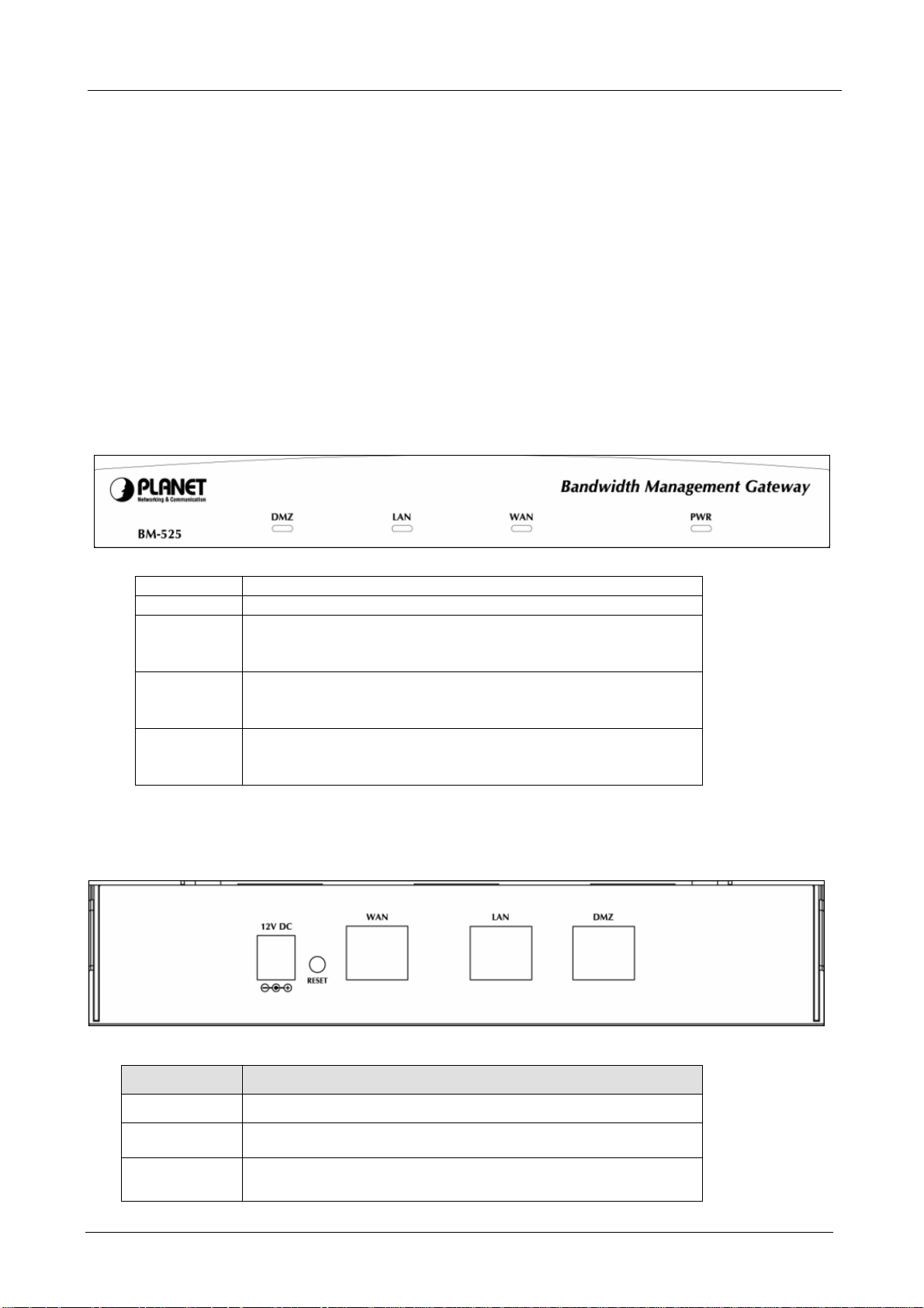
1.3 Bandw idth Managem ent Gatew ay Top View
LED Description
PWR Power is supplied to this device.
WAN Steady on indicates the port is connected to other network
device.
Blink to indicates there is traffic on the port
LAN Steady on indicates the port is connected to other network
device.
Blink to indicates there is traffic on the port
DMZ Steady on indicates the port is connected to other network
device.
Blink to indicates there is traffic on the port
1.4 Bandw idth Managem ent Gatew ay Rear Panel
Port or button Description
Power 12V DC, 1.5A
RESET
WAN
Press this button to restore to factory default settings.
Connect to your xDSL/Cable modem or other Internet
connection device
- 2 -
Page 8

BM-525 Bandwidth Management Gateway User’s Manual
LAN
Connect to your local PC, switch, or other local network
device
DMZ
Connect to your local PC, switch, or other local network
device
1.5 Specification
Product Bandwidth Management Gateway
Model BM-525
Hardware
WAN 1 x 10/100Base-TX Connections
LAN
DMZ
Button Reset button for hardware reset / factory default
System LED PWR, WAN, LAN, DMZ
Software
Maximum Bandwidth 25Mbps
Maximum concurrent
session
Management Web (English, Traditional Chinese, Simplified Chinese)
Operation Mode DMZ_NAT, DMZ_Transparent, NAT
WAN connection type in
NAT mode
Traffic Classification IP, IP subnet, and TCP/UDP port
Bandwidth Allocation Policy rules with Inbound/Outbound traffic management
Log Traffic Log, Event Log, Connection Log, Log backup by mail or
Statistics WAN port statistics and policy statistics with graph display
Firewall Security Policy-based access control
Hacker Alert and
Anomaly Flow Detection
Alarm Traffic alarm for user-defined traffic level
Other Functions Firmware Upgradeable through Web
1 x 10/100Base-TX, Auto-MDI/MDI-X
1 x 10/100Base-TX, Auto-MDI/MDI-X
20,000
PPPoE, DHCP, and Fixed IP
Guaranteed and maximum bandwidth
Scheduled in unit of 30 minutes
3 Priorities
syslog server
Stateful Packet Inspection (SPI)
Scheduled in unit of 30 minutes
Detect SYN Attack, Detect ICMP Flood, Detect UDP Flood,
Detect Ping of Death Attack, Detect Tear Drop Attack, Detect IP
Spoofing Attack, Filter IP Route Option, Detect Port Scan Attack,
Detect Land Attack, Virus-Infected Blocking, E-Mail Alert
Notification, NetBIOS Notification
Event alarm for hacker attack
The alarm message can sent to administrator by e-mail
NTP support
Configuration Backup and Restore through Web
Dynamic DNS support
Multiple NAT and multiple DMZ (mapped IP) support
Multiple server load balancing
- 3 -
Page 9

BM-525 Bandwidth Management Gateway User’s Manual
Chapter 2: System
2.1 Administration
“System” is the managing of settings such as the privileges of packets that pass through the
BM-525 and monitoring controls. The System Administrators can manage, monitor, and configure
BM-525 settings. But all configurations are “read-only” for all users other than the System
Administrator; those users are not able to change any setting of the BM-525.
- 4 -
Page 10

BM-525 Bandwidth Management Gateway User’s Manual
2.2 Admin
Define the required fields of Administrator
Administrator Name:
The user name of Administrators and Sub Administrator for the BM-525. The admin user
name cannot be removed; and the sub-admin user can be removed or configure.
The default Account: admin; Password: admin
Privilege:
The privileges of Administrators (Admin or Sub Admin). The user name of the main
Administrator is Administrator with reading / writing privilege. Administrator also can
change the system setting, log system status, and to increase or delete sub-administrator.
Sub-Admin may be created by the Admin by clicking
New Sub Admin
. Sub Admin have
only read and monitor privilege and cannot change any system setting value.
Configure:
Click Modify to change the “Sub-Administrator’s” password or click Remove to delete a “Sub
Administrator.”
- 5 -
Page 11
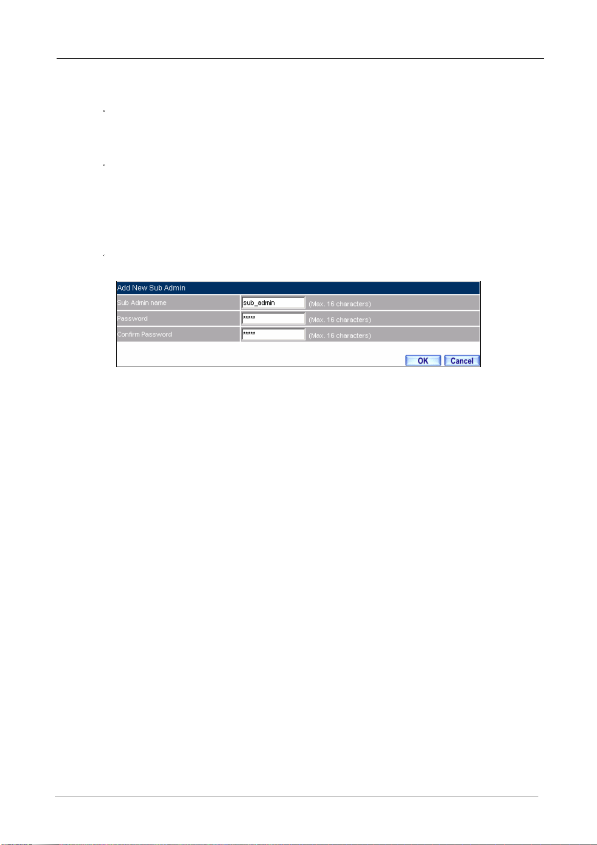
Adding a new Sub Administrator
BM-525 Bandwidth Management Gateway User’s Manual
STEP 1‒
In the Admin Web UI, click the New Sub Admin button to create a new Sub
Administrator.
STEP 2‒In the Add New Sub Administrator Web UI and enter the following setting:
Sub Admin Name: sub_admin
Password: 12345
Confirm Password: 12345
STEP 3‒Click OK to add the user or click Cancel to cancel it.
Add New Sub Admin
- 6 -
Page 12
BM-525 Bandwidth Management Gateway User’s Manual
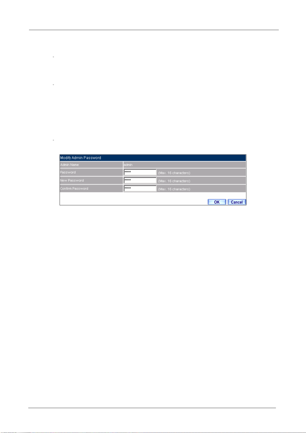
Modify the Administrator’s Password
STEP 1‒
In the Admin Web UI, locate the Administrator name you want to edit, and click on
Modify in the ConFigure field.
STEP 2‒The Modify Administrator Password Web UI will appear. Enter the following
information:
Password: admin
New Password: 52364
Confirm Password: 52364
STEP 3‒Click OK to confirm password change.
Modify Admin Password
- 7 -
Page 13
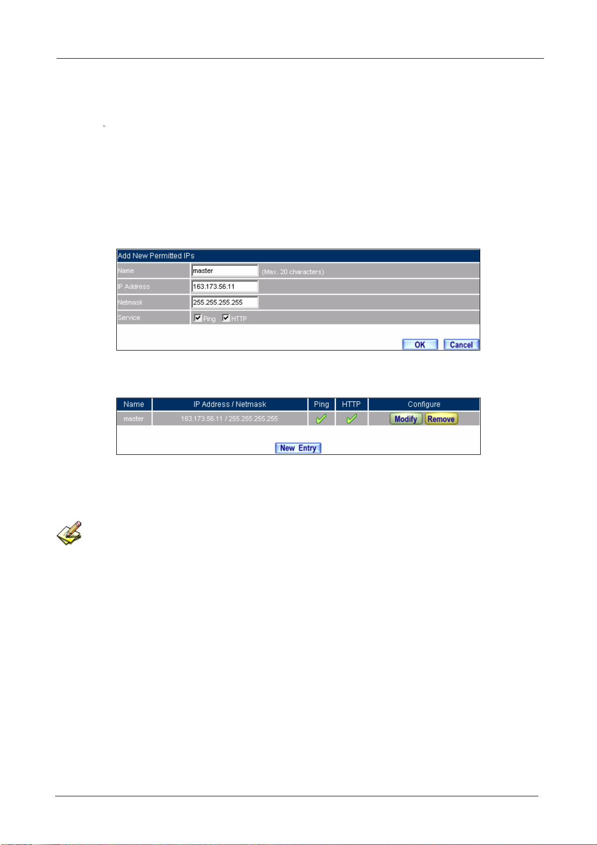
2.3 Perm itted I Ps
BM-525 Bandwidth Management Gateway User’s Manual
STEP 1‒
Add the following setting in Permitted IPs of Administration:
Name: Enter master
IP Address: Enter 163.173.56.11
Netmask: Enter 255.255.255.255
Service: Select Ping and HTTP
Click OK
Complete add new permitted IPs
Setting Permitted IPs Web UI
Complete Add New Permitted IPs
To make Permitted IPs be effective, it must cancel the Ping and We b UI selection in the Web UI of
BM-525 that Administrator enter. (LAN, WAN, or DMZ Interface)
Before canceling the Web U I selection of Interface, must set up the Permitted IPs first, otherwise, it wou ld
cause the situation of cannot enter Web UI by appointed Interface.
- 8 -
Page 14
2.4 L ogout
BM-525 Bandwidth Management Gateway User’s Manual
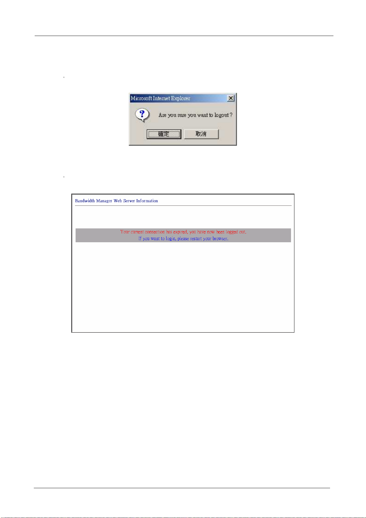
STEP 1‒
Click Logout in System to protect the system while Administrator is away.
Confirm Logout Web UI
STEP 2‒Click OK and the logout message will appear in Web UI.
Logout Web UI Message
- 9 -
Page 15
2.5 Softw are Update
BM-525 Bandwidth Management Gateway User’s Manual
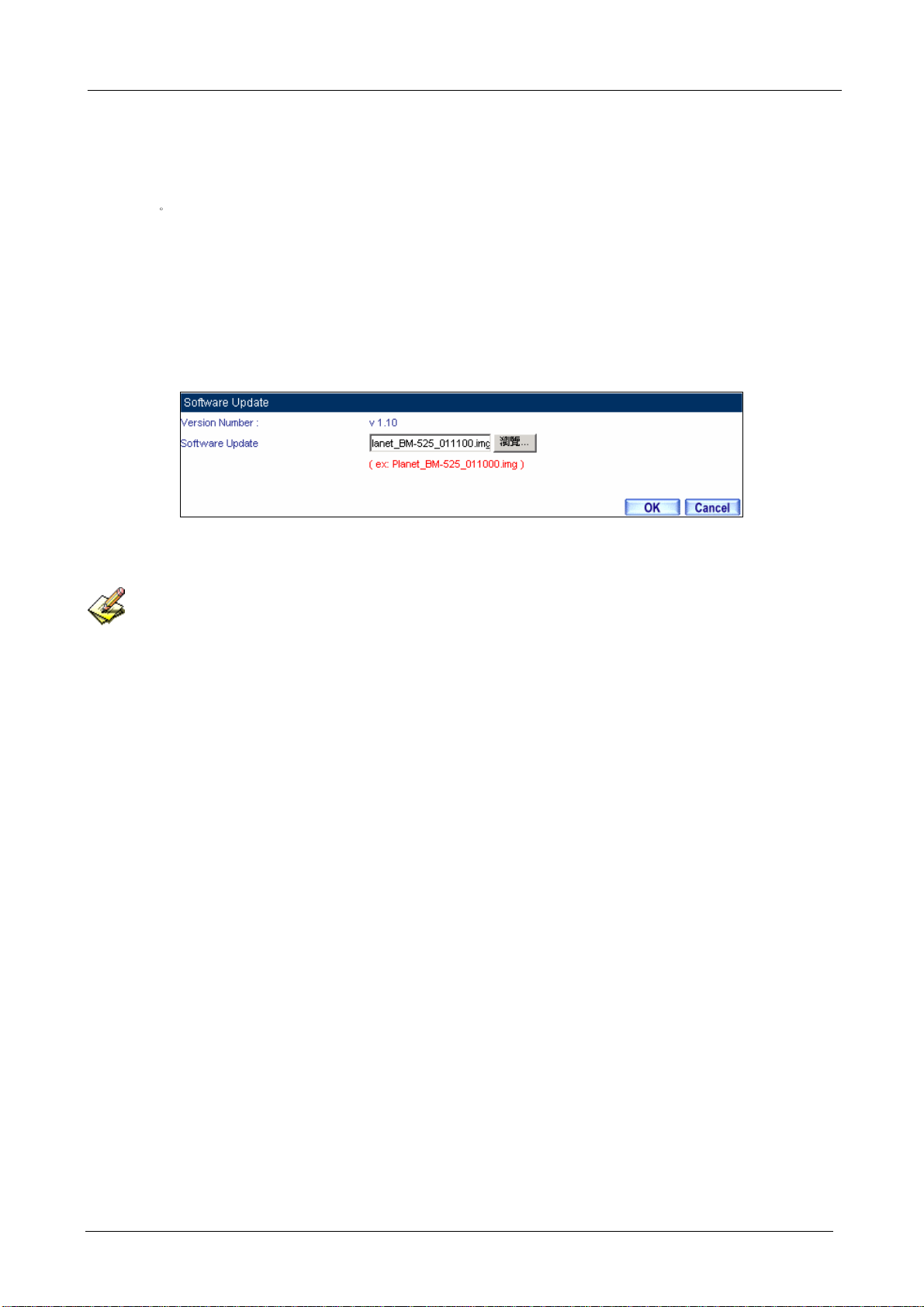
STEP 1‒
Select Software Update in System, and follow the steps below:
To obtain the version number from Version Number and obtain the latest version
from Internet. And save the latest version in the hardware of the PC, which manage
the BM-525
Click Browse and choose the latest software version file.
Click OK and the system will update automatically.
Software Update
It takes 3 minutes to update software. The sy stem will reboot after update. During the updating time,
please don’t turn off the PC or leave the Web UI. It may cause some unexpected mistakes. (Strong suggests
updating the software from LAN to avoid unexpected mistakes.)
- 10 -
Page 16

BM-525 Bandwidth Management Gateway User’s Manual
2.6 Configure
The Configure is according to the basic setting of the BM-525. In this section the definition is
Setting, Date/Time, Multiple Subnet, Route Table, DHCP, Dynamic DNS, Hosts Table, and
Language settings.
- 11 -
Page 17

BM-525 Bandwidth Management Gateway User’s Manual
2.7 Settings
BM-525 Configuration:
The Administrator can import or export the system settings. Click OK to import the file into
the BM-525 or click Cancel to cancel importing. You also can revive to default value here.
Email Settings:
Select Enable E-mail Alert Notification under E-mail Settings. This function will enable the
BM-525 to send e-mail alerts to the System Administrator when the network is being attacked
by hackers or when emergency conditions occur. (It can be set from SettingsAnomaly Flow IP in System to detect Anomaly Flow Attacks)
Web Management (WAN Interface):
The System Manager can change the port number used by HTTP port anytime. (Remote Web
UI management)
After HTTP port has changed, if the administrator wants to enter Web UI from WAN, he will have to
change the port number of browser (For example: http://61.62.108.172:8080).
MTU Setting:
It provides the Administrator to modify the networking package length anytime. Its default
value is 1500 Bytes.
- 12 -
Page 18

BM-525 Bandwidth Management Gateway User’s Manual
Dynamic Routing (RIPv2)
By enable LAN, WAN, or DMZ Port to send and receive RIPv2 packets, the BM-525
appliance can communicate with internal or external routers and dynamically update the route
table (The MIS engineers can set up routing information update timer and routing information
timeout when it stop to receive the RIPv2 packets and the router will automatically cancel the
dynamic routing table).
SIP protocol pass-through:
When user use VoIP or Video Conference has abnormally situation, can use this function to
resolve this problem.
Administration Packet Logging:
After enable this function; the BM-525 will record packet which source IP or destination
address is BM-525. And record in Traffic Log for System Manager to inquire about.
Define the required fields of Time Settings
Synchronize Time/Date:
Synchronizing the BM-525 with the System Clock. The administrator can configure the
BM-525’s date and time by either syncing to an Internet Network Time Server (NTP) or by
syncing to your computer’s clock.
GMT:
International Standard Time (Greenwich Mean Time)
Daylight saving time setting:
When user live in the time zone implement daylight saving time, during this time unit will
adjust system time as the local time.
- 13 -
Page 19

BM-525 Bandwidth Management Gateway User’s Manual
Define the required fields of Multiple Subnet
Forwarding Mode:
To display the mode that Multiple Subnet use. (NAT mode or Routing Mode)
WAN Interface Address:
The IP address that Multiple Subnet corresponds to WAN.
LAN Interface Address/Subnet Netmask:
The Multiple Subnet range.
- 14 -
Page 20

BM-525 Bandwidth Management Gateway User’s Manual
NAT Mode:
It allows Internal Network to set multiple subnet address and connect with the Internet through
different WAN IP Addresses. For example, the lease line of a company applies several real IP
Addresses 168.85.88.0/24. The company is divided into R&D department, service, sales
department, procurement department, and accounting department. The company can
distinguish each department by different subnet for the purpose of managing conveniently. The
settings are as the following
1. R&D department subnet192.168.1.1/24 (LAN) äå 168.85.88.253 (WAN)
2. Service department subnet 192.168.2.1/24 (LAN) äå 168.85.88.252 (WAN)
3. Sales department subnet 192.168.3.1/24 (LAN) äå 168.85.88.251 (WAN)
4. Procurement department subnet
192.168.4.1/24 (LAN) äå 168.85.88.250(WAN)
5. Accounting department subnet
192.168.5.1/24 (LAN) äå 168.85.88.249(WAN)
The first department (R&D department) had set while setting interface IP; the other four ones have
to be added in Multiple Subnet. After completing the settings, each department uses the different
WAN IP Address to connect to the Internet. The settings of each department are as following:
Service Sales Procurement Accounting
IP Address 192.168.2.2~254 192.168.3.2~254 192.168.4.2~254 192.168.5.2~254
Subnet Netmask 255.255.255.0 255.255.255.0 255.255.255.0 255.255.255.0
Gateway 192.168.2.1 192.168.3.1 192.168.4.1 192.168.5.1
Routing Mode:
It is the same as NAT mode approximately but does not have to correspond to the real WAN IP
address, which let internal PC to access to Internet by its own IP (External user also can use the
IP to connect with the Internet).
- 15 -
Page 21

Define the required fields of DHCP
Subnet:
The domain name of LAN
Netmask:
The LAN Netmask
Gateway:
The default Gateway IP address of LAN
Broadcast IP:
The Broadcast IP of LAN
Define the required fields of DDNS
BM-525 Bandwidth Management Gateway User’s Manual
Domain Name:
The domain name that provided by DDNS
WAN IP Address:
The WAN IP Address, which the domain name corresponds to.
Define the required fields of Host Table
Domain Name:
It can be set by System Manager. To let the internal user to access to the information that
provided by the host by this domain name
Virtual IP Address:
The virtual IP address respective to Host Table. It must be LAN or DMZ IP address.
- 16 -
Page 22

System Settings- Exporting
BM-525 Bandwidth Management Gateway User’s Manual
STEP 1‒
In System Setting Web UI, click on button next to Export System Settings to Client.
STEP 2‒When the File Download pop-up window appears, choose the destination place where to
save the exported file and click on Save. The setting value of BM-525 will copy to the
appointed site instantly.
Select the Destination Place to Save the Exported File
- 17 -
Page 23

System Settings- Importing
BM-525 Bandwidth Management Gateway User’s Manual
STEP 1‒
In System Setting Web UI, click on the Browse button next to Import System Settings
from Client. When the Choose File pop-up window appears, select the file to which
contains the saved BM-525 Settings, then click OK.
STEP 2‒Click OK to import the file into the BM-525
Enter the File Name and Destination of the Imported File
Upload the Setting File Web UI
- 18 -
Page 24

Restoring Factory Default Settings
BM-525 Bandwidth Management Gateway User’s Manual
STEP 1‒
Select Reset Factory Settings in BM-525 Configuration Web UI
STEP 2‒Click OK at the bottom-right of the page to restore the factory settings.
Reset Factory Settings
Enabling E-mail Alert Notification
STEP 1‒
STEP 2‒Select Enable E-mail Alert Notification under E-Mail Settings.
STEP 3‒
Device Name: Enter the Device Name or use the default value.
Sender Address: Enter the Sender Address. (Required by some ISPs.)
- 19 -
Page 25

BM-525 Bandwidth Management Gateway User’s Manual
STEP 4‒
SMTP Server IP: Enter SMTP server’s IP address.
STEP 5‒E-Mail Address 1: Enter the e-mail address of the first user to be notified.
STEP 6‒E-Mail Address 2: Enter the e-mail address of the second user to be notified. (Optional)
STEP 7‒Click OK on the bottom-right of the screen to enable E-mail Alert Notification.
Enable E-mail Alert Notification
Click on Mail Test to test if E-mail Address 1 and E-mail Address 2 can receive the Alert Notification
correctly.
- 20 -
Page 26

Reboot BM-525
STEP 1‒
Reboot BM-525Click Reboot button next to Reboot BM-525 Appliance.
BM-525 Bandwidth Management Gateway User’s Manual
STEP 2‒
A confirmation pop-up page will appear.
STEP 3‒Follow the confirmation pop-up page; click OK to restart BM-525.
Reboot BM-525
- 21 -
Page 27

2.8 Date/ Time
BM-525 Bandwidth Management Gateway User’s Manual
STEP 1‒
Select Enable synchronize with an Internet time Server.
STEP 2‒Click the down arrow to select the offset time from GMT.
STEP 3‒Enter the Server IP / Name with which you want to synchronize.
STEP 4‒Set the interval time to synchronize with outside servers.
System Time Setting
Click on the Sync button and then the BM-525’s date and time will be synchronized to the
Administrator’s PC
The value of Set Offset From GMT and Server IP / Name can be looking for from Assist.
If the local area executes the daylight saving time, then enable the daylight saving time setting.
- 22 -
Page 28

BM-525 Bandwidth Management Gateway User’s Manual
2.9 Multiple Subnet
Connect to the Internet through Multiple Subnet NAT or Routing Mode by the IP address that set by
the LAN user’s network card.
Preparation
To connect the Internet, WAN IP (211.22.22.22) connects with ATUR.
- 23 -
Page 29

BM-525 Bandwidth Management Gateway User’s Manual
Adding Multiple Subnet
Add the following settings in Multiple Subnet of System function:
Click on New Entry
Alias IP of LAN Interface
Enter 172.16.30.1
NetmaskEnter 255.255.255.0
WANEnter Interface IP211.22.22.22, and choose NAT in Forwarding Mode
Click OK
Complete Adding Multiple Subnet
Add Multiple Subnet Web UI
- 24 -
Page 30

BM-525 Bandwidth Management Gateway User’s Manual
WAN Interface can use Assist to enter the data.
After setting, there will be two subnets in LAN: 192.168.1.0/24 (default LAN subnet) and
172.16.30.0/24. So if LAN IP is:
192.168.1.xx, it must use NAT Mode to connect to the Internet.
162.172.50.xx, it’s also use NAT mode through WAN (The Internet Server can see your WAN IP directly).
The BM-525’s Interface Status:
WAN IP211.22.22.22
LAN Port IP192.168.1.1
LAN Port Multiple Subnet172.16.30.1
Multiple Subnet Network
- 25 -
Page 31

BM-525 Bandwidth Management Gateway User’s Manual
WAN IP (10.10.10.1) connects to the Router of ISP (10.10.10.2) directly. The IP address provided
by ISP is 162.172.50.0/24
Add the following settings in Multiple Subnet of System function:
Click on New Entry
Alias IP of LAN Interface
Enter 162.172.50.1
NetmaskEnter 255.255.255.0
WANEnter Interface IP: 10.10.10.1, and choose Routing in Forwarding Mode
Click OK
Complete Adding Multiple Subnet
Multiple Subnet Web UI Setting
After settin g, if LAN IP of BM-525 is 162.172.50.xx, it uses Routing Mode (Internet Server can see
your IP 162.172.50.xx directly)
- 26 -
Page 32

BM-525 Bandwidth Management Gateway User’s Manual
The BM-525’s Interface Status:
WAN IP10.10.10.1
LAN Port IP192.168.1.1
LAN Port Multiple Subnet162.172.50.1
Multiple Subnet Network
- 27 -
Page 33

BM-525 Bandwidth Management Gateway User’s Manual
2.1 0 Route Table
To connect two different subnet router with the BM-525 and makes them to
connect to Internet through BM-525.
Preparation
Company A: WAN (61.11.11.11) connects with ATUR to Internet
LAN subnet: 192.168.1.1/24
The Router1 which connect with LAN (10.10.10.1, support RIPv2) its LAN subnet
is 192.168.10.1/24
Company B: Router2 (10.10.10.2, support RIPv2), its LAN
subnet is 192.168.20.1/24
Company A‘s Router1 (10.10.10.1) connect directly with Company B‘s Router2 (10.10.10.2).
- 28 -
Page 34

BM-525 Bandwidth Management Gateway User’s Manual
STEP 1‒Enter the following settings in Route Table in System function:
Destination IP: Enter 192.168.10.1
Netmask: Enter 255.255.255.0¢
Gateway: Enter 192.168.1.252
Interface: Select LAN
Click OK
Add New Static Route1
STEP 2‒Enter the following settings in Route Table in System function:
Destination IP: Enter 192.168.20.1
Netmask: Enter 255.255.255.0
Gateway: Enter 192.168.1.252
Interface: Select LAN
Click OK
Add New Static Route2
- 29 -
Page 35

BM-525 Bandwidth Management Gateway User’s Manual
STEP 3‒Enter the following setting in Route Table in System function:
Destination IP: Enter 10.10.10.0
Netmask: Enter 255.255.255.0
Gateway: Enter 192.168.1.252
Interface: Select LAN
Click OK
Add New Static Route3
- 30 -
Page 36

BM-525 Bandwidth Management Gateway User’s Manual
STEP 4‒Adding successful. At this time the computer of 192.168.10.1/24, 192.168.20.1/24 and
192.168.1.1/24 can connect with each other and connect to Internet by NAT.
Route Table Setting
- 31 -
Page 37

2.1 1 DHCP
BM-525 Bandwidth Management Gateway User’s Manual
STEP 1‒
Select DHCP in System and enter the following settings:
Domain NameEnter the Domain Name
DNS Server 1: Enter the distributed IP address of DNS Server1.
DNS Server 2: Enter the distributed IP address of DNS Server2.
WINS Server 1: Enter the distributed IP address of WINS Server1.
WINS Server 2: Enter the distributed IP address of WINS Server2.
LAN Interface:
Æ Client IP Address Range 1: Enter the starting and the ending IP address
dynamically assigning to DHCP clients. The default value is 192.168.1.2 to
192.168.1.254 (it must be in the same subnet)
Æ Client IP Address Range 2: Enter the starting and the ending IP address
dynamically assigning to DHCP clients. But it must in the same subnet as
Client IP Address Range 1 and the range cannot be repeated.
DMZ Interface: the same as LAN Interface. (DMZ works only if to enable DMZ
Interface)
Leased Time: Enter the leased time for Dynamic IP. The default time is 24 hours.
Click OK and DHCP setting is completed.
- 32 -
Page 38

BM-525 Bandwidth Management Gateway User’s Manual
DHCP Web UI
When select ing Automatically Get DNS, the DNS Server will lock it as LAN Interface IP. (Using
Occasion: When the system Administrator starts Authentication, the users’ first DNS Server must be the
same as LAN Interface IP in order to enter Authentication Web UI)
- 33 -
Page 39

2.1 2 DDNS
BM-525 Bandwidth Management Gateway User’s Manual
STEP 1‒
Select Dynamic DNS in System function. Click New Entry button
Service providersSelect service providers.
Automatically fill in the WAN IPCheck to automatically fill in the WAN IP.¢
User NameEnter the registered user name.
PasswordEnter the password
Domain nameEnter Your host domain name
Click OK to add Dynamic DNS.
DDNS Web UI
Complete DDNS Setting
- 34 -
Page 40

BM-525 Bandwidth Management Gateway User’s Manual
Chart
Meaning Update
successfully
Incorrect
username or
Connecting
to server
Unknown error
password
If System Administrator had not registered a DDNS account, click on Sign up then can enter the
website of the provider.
If you do not select Automatically fill in the WAN IP and then you can enter a specific IP in WAN
IP. Let DDNS to correspond to that specific IP address.
- 35 -
Page 41

BM-525 Bandwidth Management Gateway User’s Manual
2.1 3 Host Table
STEP 1 Select Host Table in Settings function and click on New Entry
Domain Name: The domain name of the server
Virtual IP Address: The virtual IP address respective to Host Table
Click OK to add Host Table.
Add New Host Table
To use Host Table, the user PC’s first DNS Server must be the same as the LAN Port or DMZ Port IP
of BM-525. That is the default gateway.
- 36 -
Page 42

BM-525 Bandwidth Management Gateway User’s Manual
2.1 4 Language
Select the Language version (English Version, Traditional Chinese Version, or Simplified
Chinese Version) and click OK.
Language Setting Web UI
- 37 -
Page 43

BM-525 Bandwidth Management Gateway User’s Manual
Chapter 3 I nterface
In this section, the Administrator can set up the IP addresses for the office network. The
Administrator may configure the IP addresses of the LAN network, the WAN network, and the
DMZ network. The Netmask and gateway IP addresses are also configure d in this section.
- 38 -
Page 44

BM-525 Bandwidth Management Gateway User’s Manual
3.1 I nterface
Define the required fields of Interface
LAN:
Using the LAN Interface, the Administrator can set up the LAN network of BM-525.
Ping:
Select this function to allow the LAN users to ping the Interface IP Address.
HTTP:
Select to enable the user to enter the Web UI of BM-525 from Interface IP.
WAN:
The System Administrator can set up the WAN network of BM-525.
Connect Mode:
Display the current connection mode:
Æ PPPoE (ADSL user)
Æ Dynamic IP Address (Cable Modem User)
Æ Static IP Address
Æ PPTP (European User Only)
Upstream/Downstream Bandwidth:
The System Administrator can set up the correct Bandwidth of WAN network Interface here.
Auto Disconnect:
The PPPoE connection will automatically disconnect after a length of idle time (no activities).
Enter the amount of idle time before disconnection in the field. Enter “0” if you do not want
the PPPoE connection to disconnect at all.
- 39 -
Page 45

BM-525 Bandwidth Management Gateway User’s Manual
DMZ:
The Administrator uses the DMZ Interface to set up the DMZ network.
The DMZ includes:
Æ NAT Mode
In this mode, the DMZ is an independent virtual subnet. This virtual subnet
can be set by the Administrator but cannot be the same as LAN Interface.
Æ Transparent Mode: In this mode, the DMZ and WAN Interface are in the same subnet.
- 40 -
Page 46

BM-525 Bandwidth Management Gateway User’s Manual
We set up four Interface Address examples in this section:
No. Suitable
Situation
Ex1
Ex2
Ex3
Ex4
LAN
WAN
DMZ
DMZ
Example
Modify LAN Interface Settings
Setting WAN Interface Address
Setting DMZ Interface Address (NAT Mode)
Setting DMZ Interface Address (Transparent Mode)
- 41 -
Page 47

BM-525 Bandwidth Management Gateway User’s Manual
3.2 L AN
STEP 1‒Select LAN in Interface and enter the following setting:
Enter the new IP Address and Netmask
Select Ping and HTTP
Click OK
Setting LAN Interface Web UI
The default LAN IP Address is 192.168.1.1. After the Administrator setting the new LAN IP Address
on the computer , he/she has to restart the System to make the new IP address effective (when the computer
obtain IP by DHCP).
Do not cancel Web UI selection before not setting Permitted IPs yet. It will cause the Administrator
cannot be allowed to enter the BM-525’s Web UI from LAN.
- 42 -
Page 48

3.3 W AN
BM-525 Bandwidth Management Gateway User’s Manual
STEP 1‒
Select WAN in Interface and click Modify
STEP 2‒Select the Connecting way:
PPPoE (ADSL User):
1. Select PPPoE
2. Enter User Name as an account
3. Enter Password as the password
4. Select Dynamic or Fixed in IP Address provided by ISP. If you select Fixed,
please enter IP Address, Netmask, and Default Gateway.
5. Enter Max. Downstream Bandwidth and Max. Upstream Bandwidth.
(According to the flow that user apply)
6. Select Ping and Web UI
7. Click OK
PPPoE Connection
If the connection is PPPoE, you can choose Service-On-Demand for WAN Interface to connect
automatically when disconnect (suggested); or to set up Auto Disconnect if idle (not recommend)
- 43 -
Page 49

BM-525 Bandwidth Management Gateway User’s Manual
Dynamic IP Address (Cable Modem User):
1. Select Dynamic IP Address (Cable Modem User)
2. Click Renew in the right side of IP Address and then can obtain IP automatically.
3. If the MAC Address is required for ISP then click on Clone MAC Address to
obtain MAC IP automatically.
4. Hostname: Enter the hostname provided by ISP.
5. Domain Name: Enter the domain name provided by ISP.
6. User Name and Password are the IP distribution method according to
Authentication way of DHCP+ protocol (like ISP in China)
7. Enter Max. Downstream Bandwidth and Max. Upstream Bandwidth
(According to the flow that user apply)
8. Select Ping and Web UI
9. Click OK
Dynamic IP Address Connection
- 44 -
Page 50

BM-525 Bandwidth Management Gateway User’s Manual
Static IP Address
1. Select Static IP Address
2. Enter IP Addr ess, Netmask, and Default Gateway that provided by ISP
3. Enter DNS Server1 or DNS Server2
4. Enter Max. Downstream Bandwidth and Max. Upstream Bandwidth
(According to the flow that user apply)
5. Select Ping and Web UI
6.Click OK
Static IP Address Connection
When selecting Ping and We b U I on WAN network Interface, users will be able to ping the BM-525
and enter the Web UI WAN network. It may influence network security. The suggestion is to Cancel Ping
and Web UI after all the settings have finished. And if the System Administrator needs to enter UI from
WAN, he/she can use Permitted IPs to enter.
PPTP (European User Only):
1. Select PPTP (European User Only)
2. Enter the name of applied account in User Name.
3. Enter the password of applied account in Password.
4. Select Obtain an IP address automatically or Use the following IP address (use
the assigned IP address) in IP Address provided by ISP.
Æ Select Obtain as IP address automatically, please enter the value of MAC
Address, Host Name and Domain Name.
Æ Select Use the following IP address. Please enter the value of IP address,
- 45 -
Page 51

BM-525 Bandwidth Management Gateway User’s Manual
Netmask, and Default Gateway.
5. Enter value of PPTP Gateway. (Connect ID is required by some ISP provider).
6. Enter the value of MAX. Downstream Bandwidth and MAX. Upstream
Bandwidth (According to the applied bandwidth).
7. Select Ping and HTTP in Enable System Management.
8. Click OK.
- 46 -
Page 52

BM-525 Bandwidth Management Gateway User’s Manual
Dynamic IP Address Connection
If the connection is PPPoE, you can choose Service-On-Demand for WAN Interface to connect
automatically when disconnect (suggested); or to set up Auto Disconnect if idle (not recommend)
- 47 -
 Loading...