

Page 1

Bandwidth Management
Gateway
BM-500
User’s Manual
Page 2

BM-500 Bandwidth Management Gateway User’s Manual
Copyright
Copyright (C) 2004 PLANET Technology Corp. All rights reserved.
The products and programs described in this User’s Manual are licensed products of PLANET Technology, This User’s
Manual contains proprietary information protected by copyright, and this User’s Manual and all accompanying hardware,
software, and documentation are copyrighted.
No part of this User’s Manual may be copied, photocopied, reproduced, translated, or reduced to any electronic medium
or machine-readable form by any means by electronic or mechanical. Including photocopying, recording, or information
storage and retrieval systems, for any purpose other than the purchaser's personal use, and without the prior express
written permission of PLANET Technology.
Disclaimer
PLANET Technology does not warrant that the hardware will work properly in all environments and applications, and
makes no warranty and representation, either implied or expressed, with respect to the quality, performance,
merchantability, or fitness for a particular purpose.
PLANET has made every effort to ensure that this User’s Manual is accurate; PLANET disclaims liability for any
inaccuracies or omissions that may have occurred.
Information in this User’s Manual is subject to change without notice and does not represent a commitment on the part of
PLANET. PLANET assumes no responsibility for any inaccuracies that may be contained in this User’s Manual. PLANET
makes no commitment to update or keep current the information in this User’s Manual, and reserves the right to make
improvements to this User’s Manual and/or to the products described in this User’s Manual, at any time without notice.
If you find information in this manual that is incorrect, misleading, or incomplete, we would appreciate your comments and
suggestions.
CE mark Warning
This is a class B device, In a domestic environment, this product may cause radio interference, in which case the user
may be required to take adequate measures.
Trademarks
The PLANET logo is a trademark of PLANET Technology.
This documentation may refer to numerous hardware and software products by their trade names. In most, if not all cases,
these designations are claimed as trademarks or registered trademarks by their respective companies.
Customer Service
For information on customer service and support for the Bandwidth Management Gateway, please refer to the following
Website URL:
http://www.planet.com.tw
Before contacting customer service, please take a moment to gather the following information:
♦ Bandwidth Management Gateway serial number and MAC address
♦ Any error messages that displayed when the problem occurred
♦ Any software running when the problem occurred
♦ Steps you took to resolve the problem on your own
Revision
User’s Manual for PLANET BM-500
Model: BM-500
Rev: 1.0 (March, 2004)
Part No. EM-BM500
Page 3

BM-500 Bandwidth Management Gateway User’s Manual
Table of Contents
CHAPTER 1: INTRODUCTION.........................................................................................................................1
1.1 FEATURES...............................................................................................................................................................1
1.2 PACKAGE CONTENTS..............................................................................................................................................1
1.3 BANDWIDTH MANAGEMENT GATEWAY FRONT VIEW ..............................................................................................2
1.4 BANDWIDTH MANAGEMENT GATEWAY REAR PANEL..............................................................................................2
1.5 SPECIFICATION........................................................................................................................................................3
CHAPTER 2: HARDWARE INSTALLATION....................................................................................................4
2.1 INSTALLATION REQUIREMENTS...............................................................................................................................4
2.2 OPERATION MODE ..................................................................................................................................................4
2.2.1 Transparent Mode Connection Example...................................................................................................4
2.2.2 NAT Mode Connecting Example................................................................................................................5
CHAPTER 3: GETTING STARTED...................................................................................................................7
3.1 WEB CONFIGURATION.............................................................................................................................................7
3.2 SETTING UP IN TRANSPARENT MODE.....................................................................................................................8
3.3 SETTING UP IN NAT MODE...................................................................................................................................10
CHAPTER 4: WEB CONFIGURATION...........................................................................................................12
4.1 SYSTEM.................................................................................................................................................................12
4.1.1 Admin...........................................................................................................................................................13
4.1.2 Settings........................................................................................................................................................16
4.1.3 Date/Time....................................................................................................................................................23
4.1.4 Language.....................................................................................................................................................24
4.1.5 Permitted IPs...............................................................................................................................................25
4.1.6 Multiple NAT................................................................................................................................................28
4.1.7 Hacker Alert.................................................................................................................................................31
4.1.8 Route Table.................................................................................................................................................33
4.1.9 DHCP...........................................................................................................................................................37
4.1.10 DNS Proxy.................................................................................................................................................39
4.1.11 DDNS.........................................................................................................................................................40
4.1.12 Logout........................................................................................................................................................45
4.1.13 Software Update.......................................................................................................................................46
4.2 INTERFACE ............................................................................................................................................................48
4.3 ADDRESS...............................................................................................................................................................53
4.3.1 LAN...............................................................................................................................................................53
4.3.2 LAN Group...................................................................................................................................................57
Page 4

BM-500 Bandwidth Management Gateway User’s Manual
4.3.3 WAN.............................................................................................................................................................60
4.3.4 WAN Group.................................................................................................................................................63
4.4 SERVICE................................................................................................................................................................67
4.4.1 Pre-defined..................................................................................................................................................67
4.4.2 Custom.........................................................................................................................................................68
4.4.3 Group ...........................................................................................................................................................72
4.5 SCHEDULE.............................................................................................................................................................75
4.6 QOS......................................................................................................................................................................78
4.7 AUTHENTICATION ..................................................................................................................................................82
4.8 POLICY..................................................................................................................................................................86
4.8.1 Outgoing......................................................................................................................................................86
4.8.2 Incoming......................................................................................................................................................91
4.9 CONTENT FILTERING .............................................................................................................................................97
4.9.1 URL Blocking ..............................................................................................................................................97
4.9.2 General Blocking......................................................................................................................................101
4.10 VIRTUAL SERVER..............................................................................................................................................102
4.10.1 Mapped IP...............................................................................................................................................103
4.10.2 Virtual Server..........................................................................................................................................106
4.11 LOG ...................................................................................................................................................................115
4.11.1 Traffic Log.................................................................................................................................................115
4.11.2 Event Log..................................................................................................................................................118
4.11.3 Connection Log.......................................................................................................................................121
4.11.4 Log Backup .............................................................................................................................................123
4.12 ALARM ...............................................................................................................................................................126
4.12.1 Traffic Alarm............................................................................................................................................126
4.12.2 Event Alarm.............................................................................................................................................127
4.13 ACCOUNTING REPORT ......................................................................................................................................130
4.13.1 Outbound Accounting Report...............................................................................................................130
4.13.2 Inbound....................................................................................................................................................135
4.14 STATISTICS........................................................................................................................................................140
4.14.1 WAN Statistics........................................................................................................................................140
4.14.2 Policy Statistics.......................................................................................................................................141
4.15 STATUS..............................................................................................................................................................144
4.15.1 Interface Status.......................................................................................................................................144
4.15.2 ARP Table................................................................................................................................................145
4.15.3 DHCP Clients..........................................................................................................................................146
Page 5

BM-500 Bandwidth Management Gateway User’s Manual
Chapter 1: Introduction
BM-500 is specifically designed for SOHO networks. It has built-in 4-port 10/100Mbps Ethernet LAN ports and
NAT function. Thus, no broadband router is required for users which have only one public IP address. It also
supports virtual server, Multi-DMZ and dynamic DNS function which is very useful for users to share local
resource to Internet users.
For bandwidth management, packets can be classified based on IP address, IP subnet and TCP/UDP port
number. The device has more than 40 of the most common protocols such as H.323, Oracle, HTTP, FTP, etc.
for ease of definition; the administrator can then define policies to ensure committed and maximum bandwidth
levels for inbound / outbound traffic in each class. The administrator can also define three priority levels for
each policy to ensure that high priority packets receive the maximum available bandwidth. In addition, each
policy can have a schedule defined for when the policy is activated or inactivated in increments of 30 minutes.
Both the NAT mode and transparent mode are supported, therefore allowing the existing network structure to
remain the same without reconfiguring. The BM-500 provides policy-based firewall protection and several
hacker protections to prevent any hacker attack. Besides, the comprehensive alarm and log function allow
the network Management Gateway to easily enhance the security of local network.
1.1 Features
♦ Provides four 10/100Mbps LAN port and one 10/100Mbps WAN port
♦ Supports NAT mode and transparent mode
♦ Transparent mode requires no changing for the original network structure
♦ Traffic classification bases on IP, IP range/subnet, TCP/UDP port range
♦ Guaranteed and maximum bandwidth with 3 level of priorities
♦ Dynamic and prioritized bandwidth sharing with fairness between equal-level priority
♦ Assigns daily and weekly access schedule to each individual policy
♦ Professional Network Log and Accounting Report
♦ Supports MRTG-like Traffic Statistics, easy to trace and analyze
♦ Provides Multi-Servers Load Balancing
♦ Provides Dynamic DNS and DHCP server functions
♦ Supports Content Filter on scheduled time
♦ Supports Virtual Server and IP mapping (Multi-DMZ Host)
♦ Supports Multi-language web UI, easy to manage
♦ Support user authentication based user’s user name and password
1.2 Package Contents
The following items should be included:
♦ Bandwidth Management Gateway
♦ Power Adapter
♦ Quick Installation Guide
♦ User’s Manual CD
If any of the contents are missing or damaged, please contact your dealer or distributor immediately.
- 1 -
Page 6
BM-500 Bandwidth Management Gateway User’s Manual
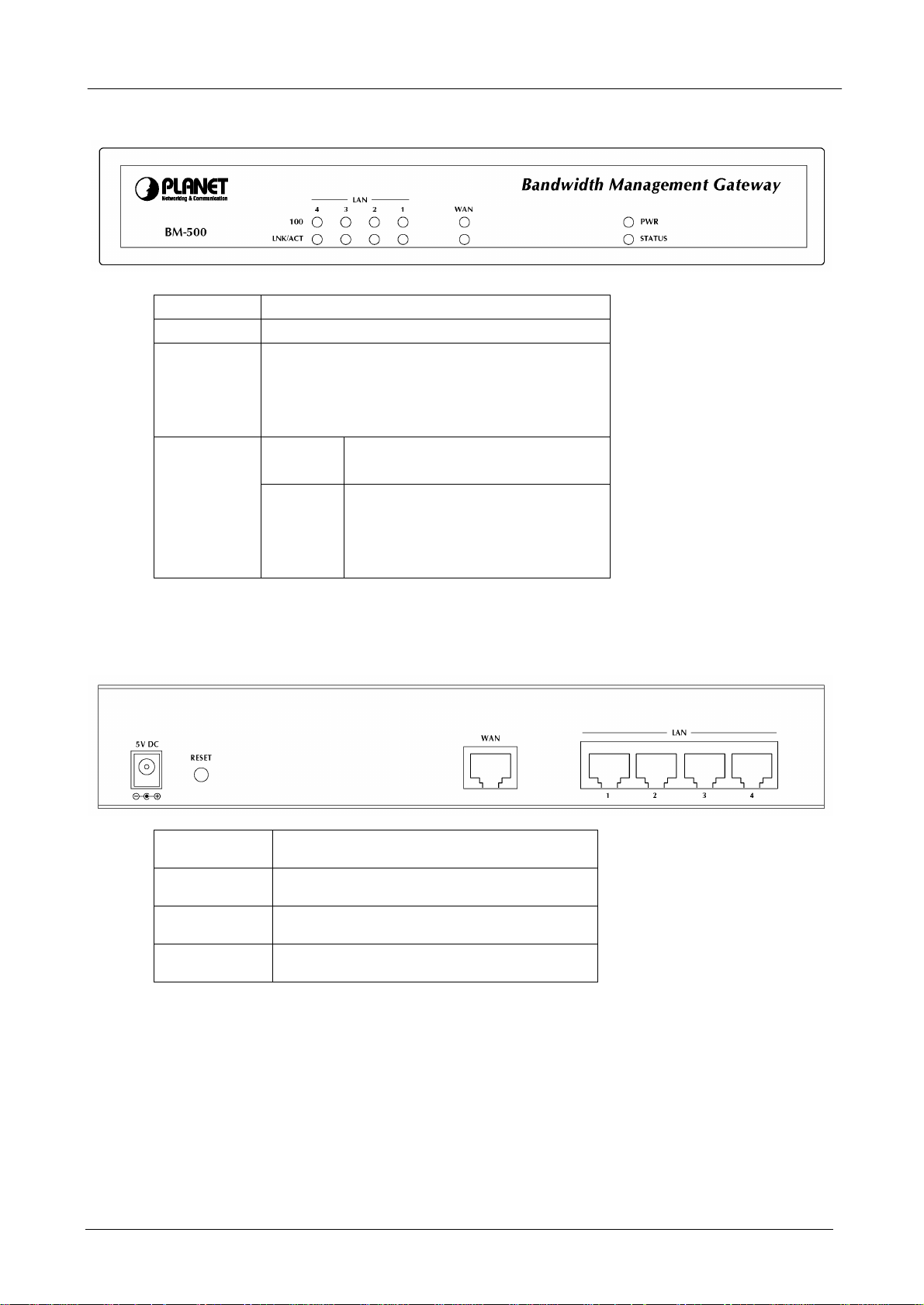
1.3 Bandwidth Management Gateway Front View
LED Description
PWR Power is supplied to this device.
STATUS Blinks to indicate this devise is being turned on.
After one minute, this LED indicator will stop
blinking, it means this device is now ready to
use.
WAN & LAN
100 Steady on indicates the port operate
on 100Mbps speed
LNK/ACT Steady on indicates the port is
connected to other network device.
Blink to indicates there is traffic on
the port
1.4 Bandwidth Management Gateway Rear Panel
Port or
button
RESET Press this button to restore to factory
WAN Connect to your xDSL/Cable modem
LAN 1 to 4 Connect to your local PC, switch or
Description
default settings.
or other Internet connection device
other local network device
- 2 -
Page 7

BM-500 Bandwidth Management Gateway User’s Manual
1.5 Specification
Product Bandwidth Management Gateway
Model BM-500
Hardware
WAN 1 x 10/100Base-TX Connections
LAN 4 x 10/100Base-TX, Auto-MDI/MDI-X
Button Reset button fro hardware reset / factory default
System LED System: PWR, STATUS
Network: LNK/ACT, 100
Power 5V DC, 2.4A
Operating Environment Temperature: 0~50°C
Relative Humidity: 5%~90%
Dimension W x D x H 220 x 149 x 37 mm
Regulatory FCC, CE Mark
Software
Maximum Bandwidth Transparent: 10Mbps
NAT: 8Mbps
NAT + logging + statistics: 3Mbps
Maximum concurrent
session
Management Web (English, Traditional Chinese, Simplified Chinese )
Operation Mode Transparent, NAT
WAN connection type in NAT
mode
Traffic Classification IP, IP subnet, TCP/UDP port
Bandwidth Allocation Policy rules with Inbound/Outbound traffic management
Log Traffic Log, Event Log, Connection Log, Log backup by mail or syslog
Statistics WAN port statistics and policy statistics with graph display
Firewall Security Policy-based access control
Hacker Alert Detect SYN Attack, Detect ICMP Flood, Detect UDP Flood, Detect Ping
Alarm w Traffic alarm for user-defined traffic level
Other Functions Firmware Upgradeable through Web
5000
PPPoE, DHCP and Fixed IP
Guaranteed and maximum bandwidth
Scheduled in unit of 30 minutes
3 Priorities
server
Stateful Packet Inspection (SPI)
Scheduled in unit of 30 minutes
of Death Attack, Detect Tear Drop Attack, Detect IP Spoofing Attack,
Filter IP Route Option, Detect Port Scan Attack, Detect Land Attack
w Event alarm for hacker attack
w The alarm message can sent to administrator by e-mail
NTP support
Configuration Backup and Restore through Web
Dynamic DNS support
Multiple NAT and multiple DMZ ( mapped IP) support
Multiple server load balancing
- 3 -
Page 8

BM-500 Bandwidth Management Gateway User’s Manual
Chapter 2: Hardware Installation
2.1 Installation Requirements
Before installing the Bandwidth Management Gateway, make sure your network meets the following
requirements.
- Mechanical Requirements
The Bandwidth Management Gateway is to be installed between your Internet connection and local area
network. The Bandwidth Management Gateway can be placed on the table or rack. Locate the unit near
the power outlet.
- Electrical Requirements
The Bandwidth Management Gateway is a power-required device, it means, the Bandwidth Management
Gateway will not work until it is powered. If your networked PCs will need to transmit data all the time,
please consider use an UPS (Uninterrupted Power Supply) for your Bandwidth Management Gateway. It
will prevent you from network data loss. In some area, installing a surge suppression device may also help
to protect your Bandwidth Management Gateway from being damaged by unregulated surge or current to
the Bandwidth Management Gateway.
- Network Requirements
In order for Bandwidth Management Gateway to manage traffic, the traffic must pass through Bandwidth
Management Gateway at a useful point in a network. In most situations, the bandwidth Management
Gateway should be placed behind the Internet connection device.
This deployment allows the network administers to control all bandwidth based on business priorities and
give business-critical and time-sensitive applications guarantee bandwidth and higher priority.
Business-critical applications can receive maximum performance while other less urgent traffic is still
available on remaining bandwidth. Bandwidth Management Gateway also provides comprehensive
security, log and statistics functions to help monitor network and bandwidth usage and allow adjustment of
the bandwidth management policies accordingly.
2.2 Operation Mode
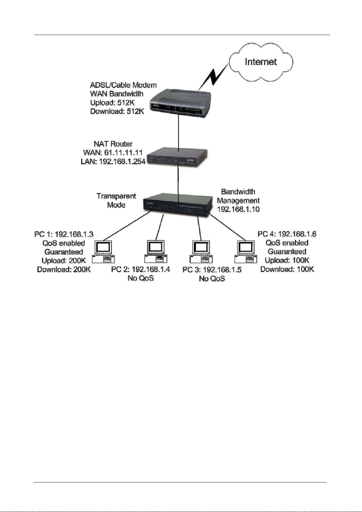
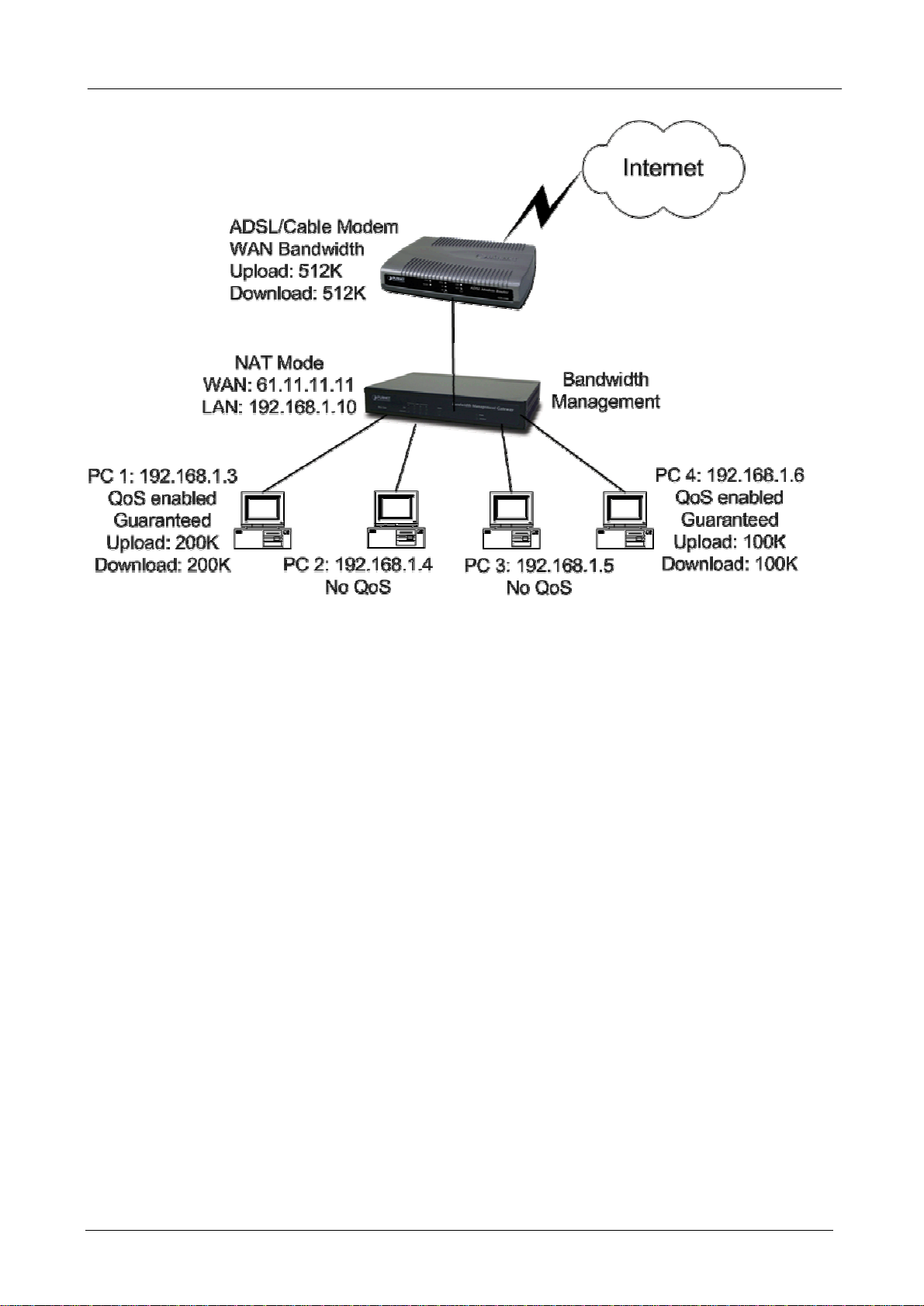
BM-500 supports two operation modes, Transparent and NAT. In transparent mode, BM-500 works as
proxy with forward LAN packet to WAN and forward WAN packet to LAN. The LAN and WAN side IP
addresses are in the same subnet. In NAT mode, LAN side user will share one public IP address of WAN
port to make Internet connection. Please find the following two pictures for example.
2.2.1 Transparent Mode Connection Example
- 4 -
Page 9
BM-500 Bandwidth Management Gateway User’s Manual
All the WAN and LAN side IP addresses are on the same subnet.
2.2.2 NAT Mode Connecting Example
- 5 -
Page 10
BM-500 Bandwidth Management Gateway User’s Manual
LAN and WAN side IP addresses are on the different subnet.
- 6 -
Page 11

BM-500 Bandwidth Management Gateway User’s Manual
Chapter 3: Getting Started
3.1 Web Configuration
STEP 1:
Connect both the Administrator’s PC and the LAN port of the Bandwidth Management Gateway to a hub or
switch. Make sure there is a link light on the hub/switch for both connections. The Bandwidth Management
Gateway has an embedded web server used for management and configuration. Use a web browser to
display the configurations of the Bandwidth Management Gateway (such as Internet Explorer 4(or above) or
Netscape 4.0(or above) with full java script support). The default IP address of the Bandwidth Management
Gateway is 192.168.1.1 with a subnet mask of 255.255.255.0. Therefore, the IP address of the Administrator
PC must be in the range between 192.168.1.2– 192.168.1.254
If the company’s LAN IP Address is not subnet of 192.168.1.0, (i.e. LAN IP Address is 172.16.0.1), then the
Administrator must change his/her PC IP address to be within the same range of the LAN subnet (i.e.
172.16.0.2). Reboot the PC if necessary.
By default, the Bandwidth Management Gateway is shipped with its DHCP Server function enabled. This
means the client computers on the LAN network including the Administrator PC can set their TCP/IP settings
to automatically obtain an IP address from the Bandwidth Management Gateway.
The following table is a list of private IP addresses. These addresses may not be used as a WAN IP address.
10.0.0.0 ~ 10.255.255.255
172.16.0.0 ~ 172.31.255.255
192.168.0.0 ~ 192.168.255.255
STEP 2:
Once the Administrator PC has an IP address on the same network as the Bandwidth Management Gateway,
open up an Internet web browser and type in http://192.168.1.1 in the address bar.
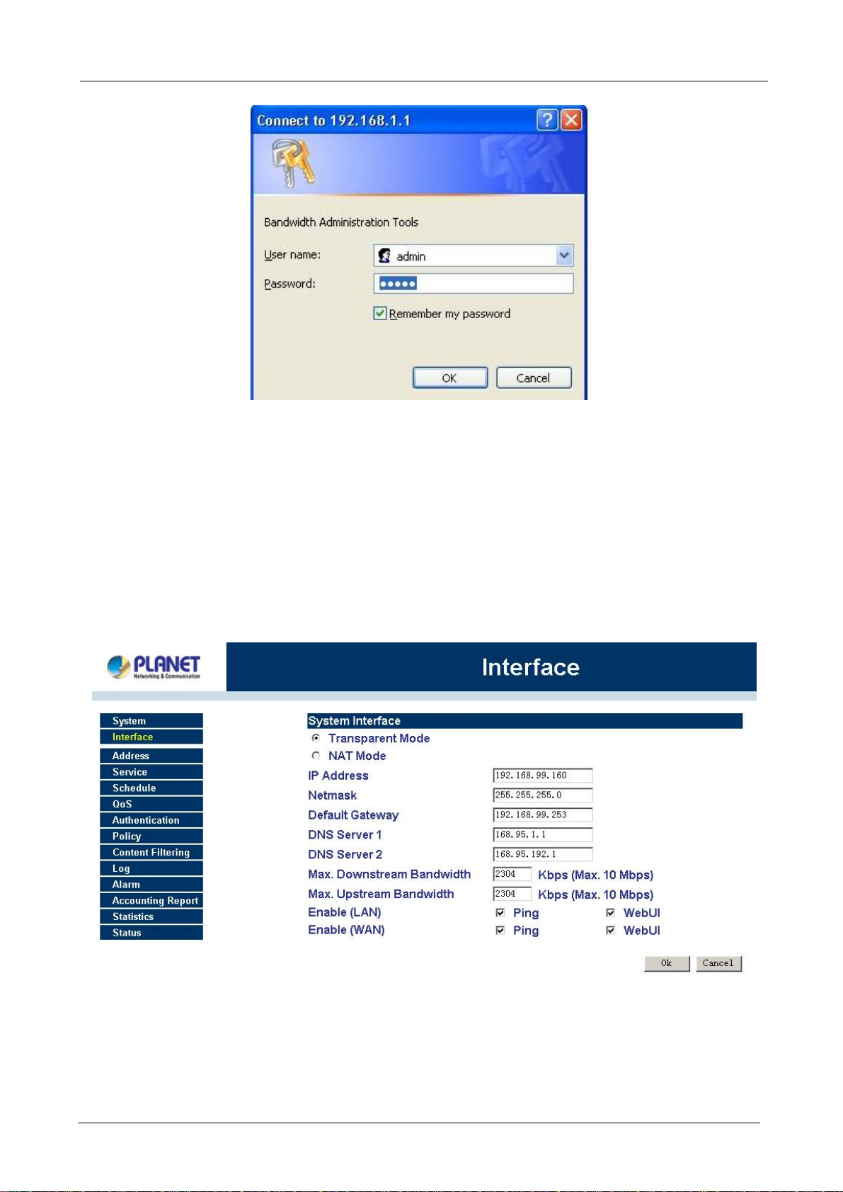
A pop-up screen will appear and prompt for a username and password. A username and password is required
to connect to the Bandwidth Management Gateway. Enter the default login username and password of
Administrator (see below).
Username: admin
Password: admin
Click OK.
- 7 -
Page 12
BM-500 Bandwidth Management Gateway User’s Manual
3.2 Setting Up in Transparent Mode
STEP 1:
After entering the username and password, the Bandwidth Management Gateway WEB UI screen will display.
Select the Interface tab on the left menu and a sub-function list will be displayed.
• Select Transparent Mode.
• Enter required information to their corresponding fields.
LAN interface IP Address
NetMask
Default Gateway
DNS Server
.
Note: The above figures are only examples. Please fill in the appropriate IP address information provided to
you by the ISP.
STEP 2:
Click on the Policy tab from the main function menu, and then click on Outgoing from the sub-function list.
STEP 3:
- 8 -
Page 13
BM-500 Bandwidth Management Gateway User’s Manual
Click on New Entry button.
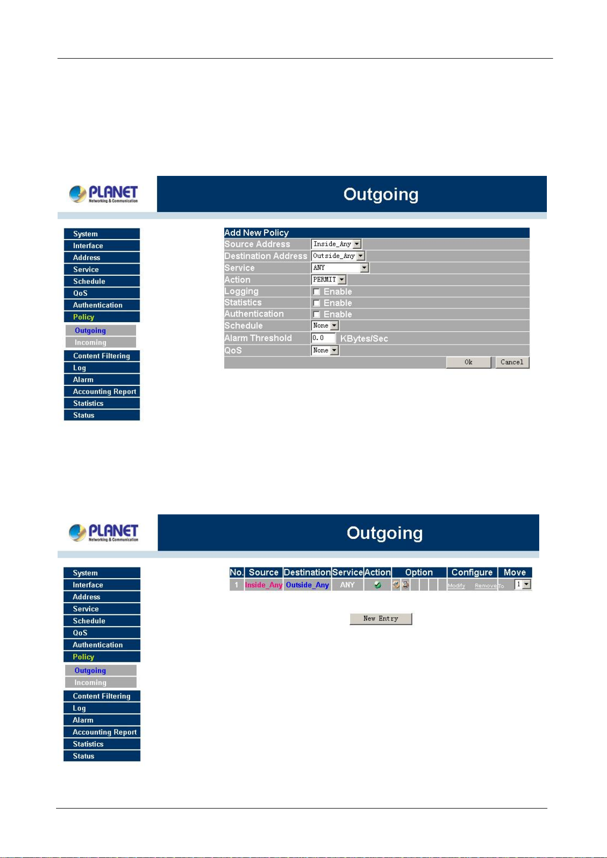
STEP 4:
When the New Entry option appears, enter the following configuration:
Source Address – select “Inside_Any”
Destination Address – select “Outside_Any”
Service - select “ANY”
Action - select “Permit”
Click on OK to apply the changes.
STEP 5:
The configuration is successful when the screen below is displayed. Make sure that all the computers that
are connected to the LAN port have their Default Gateway IP Address set to the Bandwidth Management
Gateway’s LAN IP Address (i.e. 192.168.1.1). At this point, all the computers on the LAN network should gain
access to the Internet immediately. If a Bandwidth Management Gateway filter function is required, please
refer to the Policy section in the user’s manual.
- 9 -
Page 14
BM-500 Bandwidth Management Gateway User’s Manual
3.3 Setting Up in NAT Mode
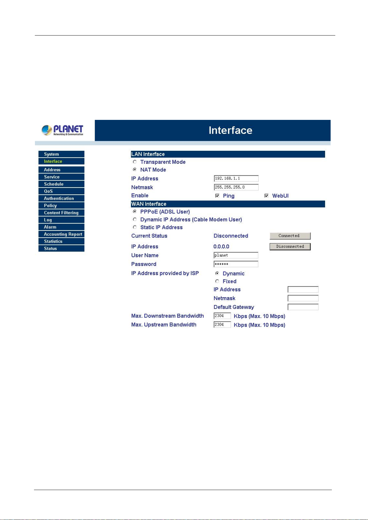
STEP 1:
After entering the Bandwidth Management Gateway WEB UI screen, select the Interface tab on the left menu
and a sub-function list will be displayed.
Select the NAT Mode.
Enter the required information to their corresponding fields.
LAN Interface IP Address 192.168.1.1
NetMask 255.255.255.0
Enter the information that your ISP provided.
STEP 2:
Click on the Policy tab from the main function menu, and then click on Outgoing from the sub-function list.
Click on the Policy tab from the main function menu, and then click on Incoming from the sub-function list.
STEP 3:
Click on New Entry button.
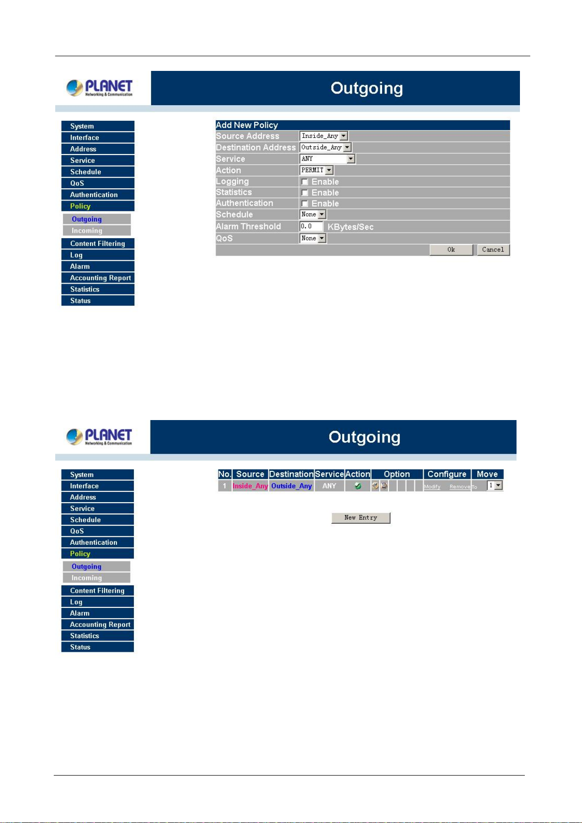
STEP 4:
When the New Entry option appears, enter the following configuration:
Source Address – select “Inside_Any”
Destination Address – select “Outside_Any”
Service - select “ANY”
Action - select “Permit”
Click on OK to apply the changes.
- 10 -
Page 15
BM-500 Bandwidth Management Gateway User’s Manual
STEP 5:
The configuration is successful when the screen below is displayed. Make sure that all the computers that
are connected to the LAN port have their Default Gateway IP Address set to the Bandwidth Management
Gateway’s LAN IP Address (i.e. 192.168.1.1). At this point, all the computers on the LAN network should
gain access to Internet immediately. If a Bandwidth Management Gateway filter function is required,
please refer to Address and Policy sections.
- 11 -
Page 16

BM-500 Bandwidth Management Gateway User’s Manual
Chapter 4: Web Configuration
4.1 System
The Bandwidth Management Gateway Administration and monitoring control is set by the System
Administrator. The System Administrator can add or modify System settings and monitoring mode. The sub
Administrators can only read System settings but not modify them. In System, the System Administrator can:
1. Add and change the sub Administrator’s names and passwords;
2. Back up all Bandwidth Management Gateway settings into local files;
3. Set up alerts for Hackers invasion.
“System” is the managing of settings such as the privileges of packets that pass through the Bandwidth
Management Gateway and monitoring controls. Administrators may manage, monitor, and configure
Bandwidth Management Gateway settings. All configurations are “read-only” for all users other than the
Administrator; those users are not able to change any settings for the Bandwidth Management Gateway.
Admin: has control of user access to the Bandwidth Management Gateway. He/she can add/remove users
and change passwords.
Setting: The Administrator may use this function to backup Bandwidth Management Gateway configurations
and export (save) them to an “Administrator” computer or anywhere on the network; or restore a
configuration file to the device; or restore the Bandwidth Management Gateway back to default factory
settings. Under Setting, the Administrator may enable e-mail alert notification. This will alert Administrator(s)
automatically whenever the Bandwidth Management Gateway has experienced unauthorized access or a
network hit (hacking or flooding). Once enabled, an IP address of a SMTP (Simple Mail Transfer protocol)
Server is required. Up to two e-mail addresses can be entered for the alert notifications.
Date/Time: This function enables the Bandwidth Management Gateway to be synchronized either with an
Internet Server time or with the client computer’s clock.
Language: Both Chinese and English are supported in the Bandwidth Management Gateway.
Multiple NAT Multiple NAT allows local port to set multiple subnet works and connect with the Internet
through different WAN IP Addresses.
Address: Enables the Administrator to authorize specific internal/external IP address(s for Management
Gateway.
Hack Alert When abnormal conditions occur, the Bandwidth Management Gateway will send an e-mail alert
to notify the Administrator, and also display warning messages in the Event window of Alarm.
Route Table Use this function to enable the Administrator to add static routes for the networks when the
dynamic route is not efficient enough.
DHCP Administrator can configure DHCP (Dynamic Host Configuration Protocol) settings for the LAN (LAN)
network.
Dynamic DNS The Dynamic DNS (require Dynamic DNS Service) allows you to alias a dynamic IP address
- 12 -
Page 17
BM-500 Bandwidth Management Gateway User’s Manual
to a static hostname, allowing your device to be more easily accessed by specific name. When this function is
enabled, the IP address in Dynamic DNS Server will be automatically updated with the new IP address
provided by ISP
Logout Administrator logs out the Bandwidth Management Gateway. This function protects your system
while you are away.
Software Update The administrator can update the device’s software with the latest version.
Administrators may visit distributor’s web site to download the latest firmware. Administrators may update
the device firmware to optimize its performance and keep up with the latest fixes for intruding attacks.
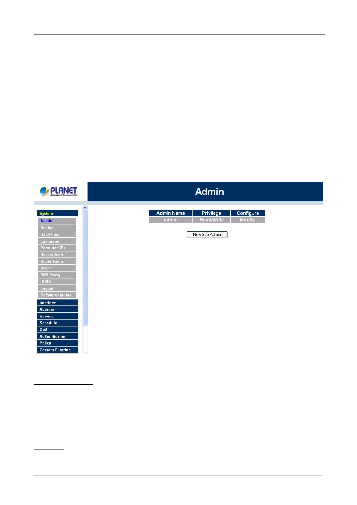
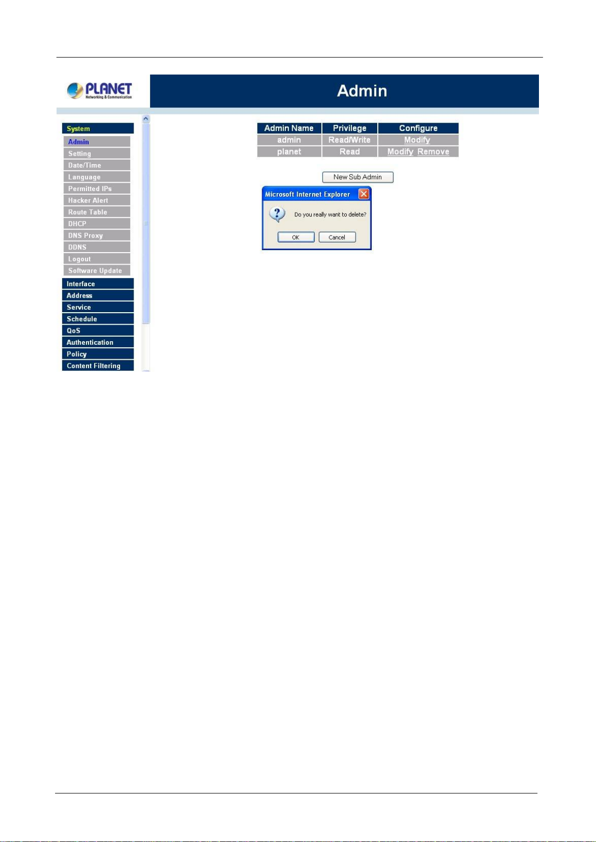
4.1.1 Admin
On the left hand menu, click on Setup, and then select Admin below it. The current list of Administrator(s)
shows up.
çç
Settings of the Administration table
Administrator Name: The username of Administrators for the Bandwidth Management Gateway. The user
admin cannot be removed.
Privilege: The privileges of Administrators (Admin or Sub Admin)
The username of the main Administrator is Administrator with read / write privilege.
Sub Admins may be created by the Admin by clicking
privilege.
Configure: Click Modify to change the “Sub Administrator’s” password and click Remove to delete a “Sub
Administrator.”
New Sub Admin
- 13 -
. Sub Admins have read only
Page 18
BM-500 Bandwidth Management Gateway User’s Manual
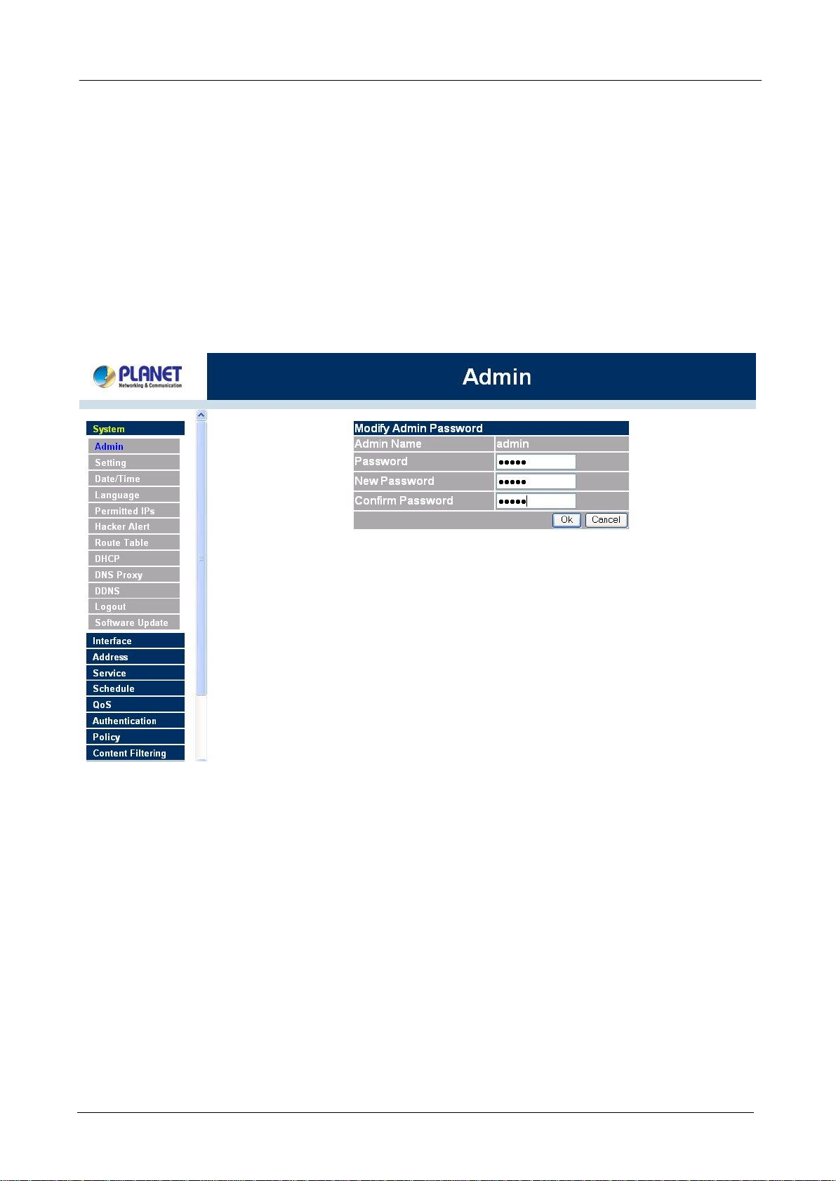
Changing the Main/Sub-Administrator’s Password
Step 1. The Modify Administrator Password window will appear. Enter in the required information:
n Password: enter original password.
n New Password: enter new password
n Confirm Password: enter the new password again.
Step 2. Click OK to confirm password change or click Cancel to cancel it.
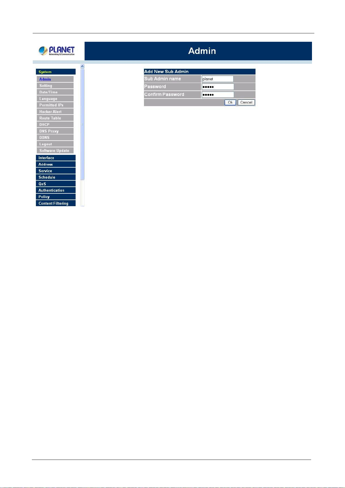
Adding a new Sub Administrator
Step 1. In the Add New Sub Administrator window:
n Sub Admin Name: enter the username of new Sub Admin.
n Password: enter a password for the new Sub Admin.
n Confirm Password: enter the password again.
Step 2. Click OK to add the user or click Cancel to cancel the addition.
- 14 -
Page 19
BM-500 Bandwidth Management Gateway User’s Manual
Removing a Sub Administrator
Step 1. In the Administration table, locate the Administrator name you want to edit, and click on the
Remove option in the Configure field.
Step 2. The Remove confirmation pop-up box will appear. Click OK to remove that Sub Admin or click
Cancel to cancel.
- 15 -
Page 20
BM-500 Bandwidth Management Gateway User’s Manual
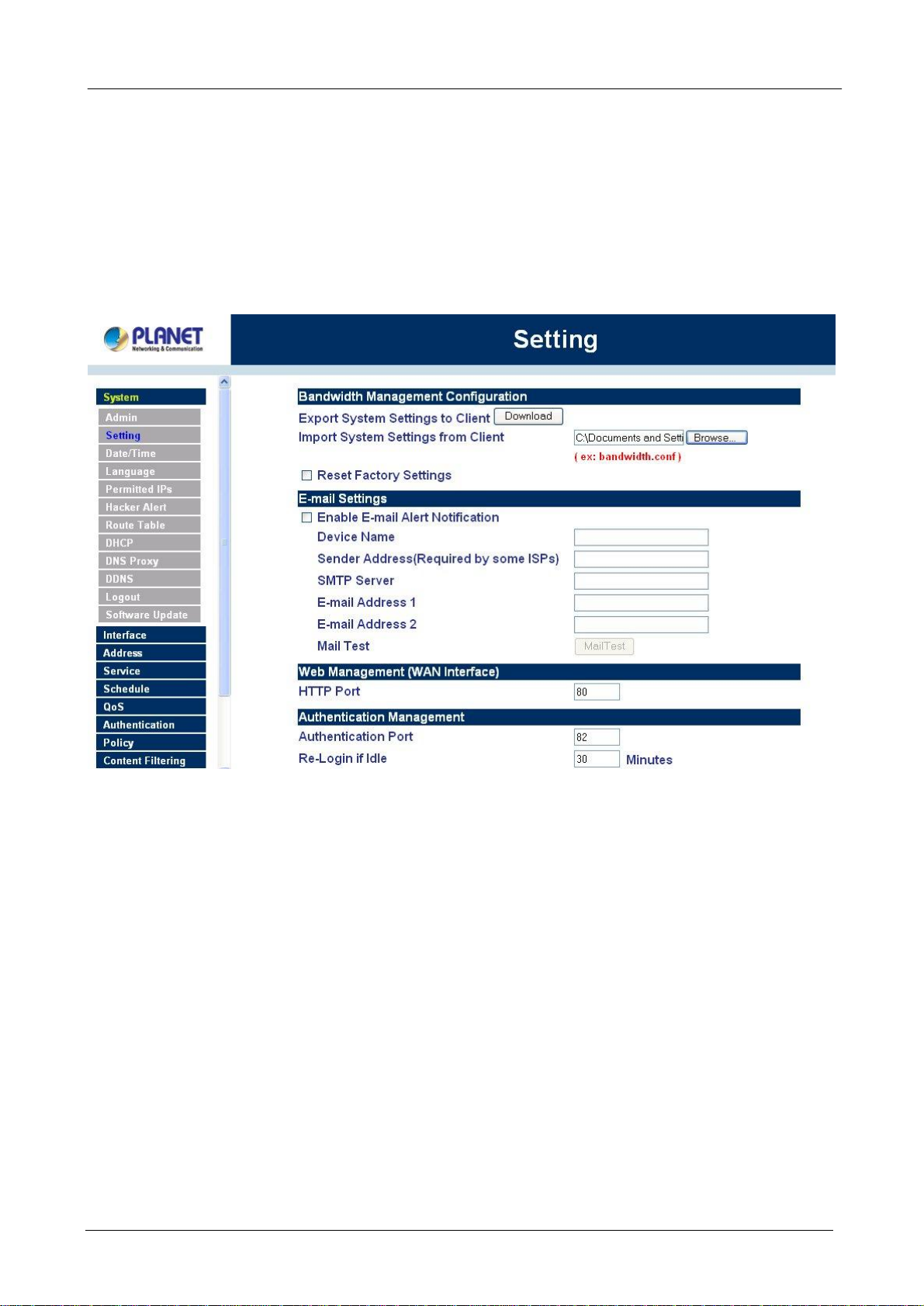
4.1.2 Settings
The Administrator may use this function to backup Bandwidth Management Gateway configurations and
export (save) them to an “Administrator” computer or anywhere on the network; or restore a configuration
file to the device; or restore the Bandwidth Management Gateway back to default factory settings.
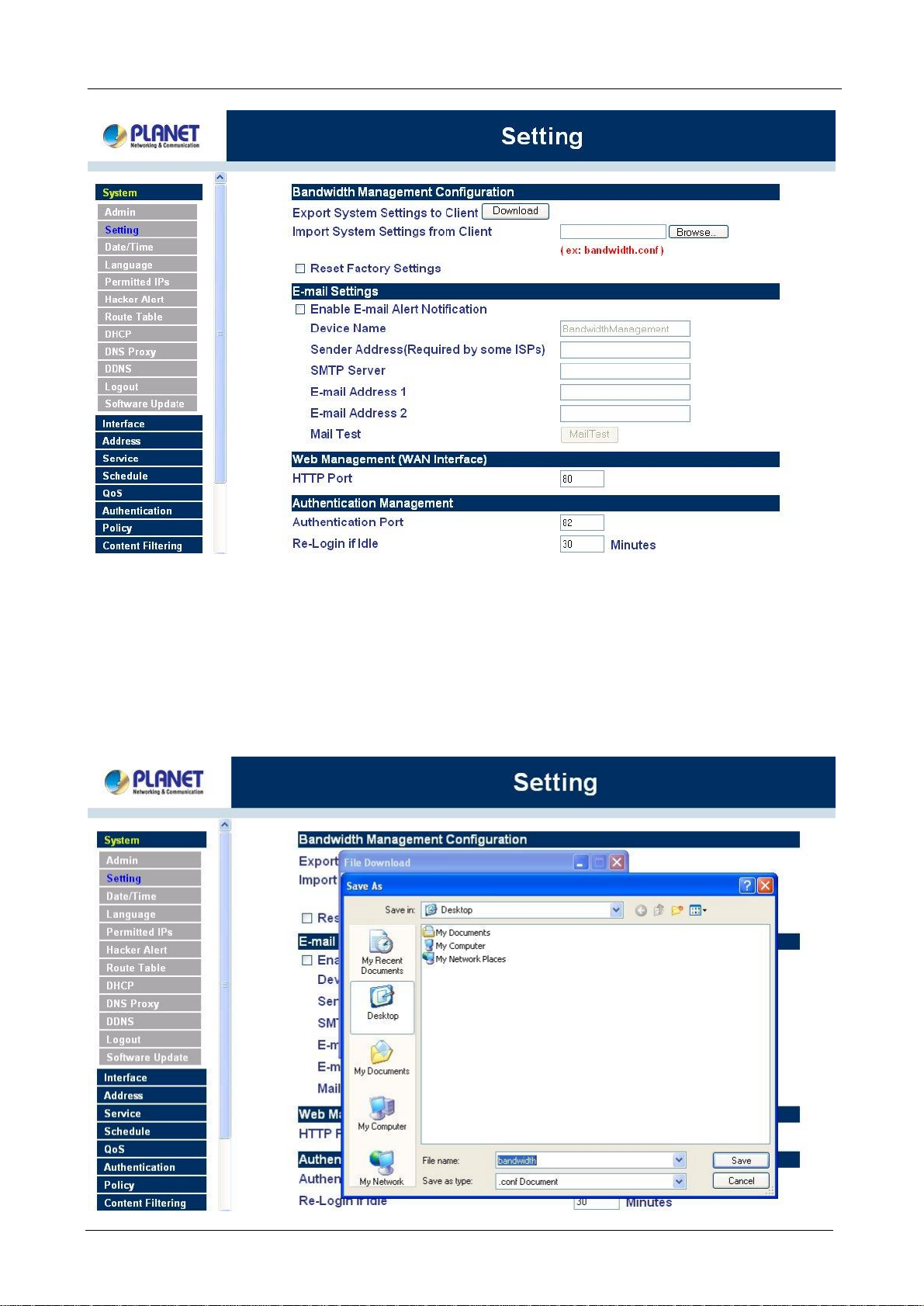
Entering the Settings window
Click Setting in the System menu to enter the Settings window. The Bandwidth Management Gateway
Configuration settings will be shown on the screen.
- 16 -
Page 21
çç
BM-500 Bandwidth Management Gateway User’s Manual
Exporting Bandwidth Management Gateway settings
Step 1. Under Bandwidth Management Configuration, click on the Download button next to Export
System Settings to Client.
Step 2. When the File Download pop-up window appears, choose the destination place to save the
exported file. The Administrator may choose to rename the file if preferred.
- 17 -
Page 22
BM-500 Bandwidth Management Gateway User’s Manual
Importing Bandwidth Management Gateway settings
Under Bandwidth Management Gateway Configuration, click on the Browse button next to Import
System Settings. When the Choose File pop-up window appears, select the file which contains the saved
Bandwidth Management Gateway Settings, then click OK.
Click OK to import the file into the Bandwidth Management Gateway or click Cancel to cancel importing.
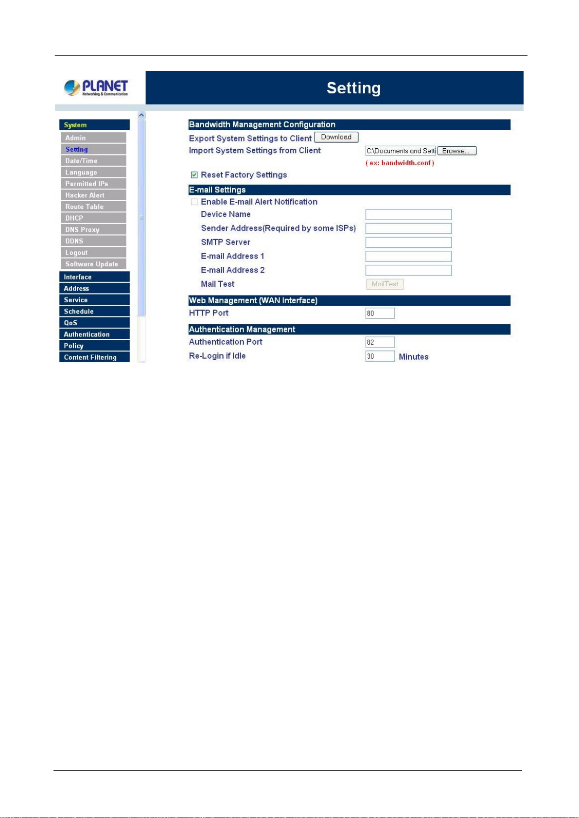
Restoring Factory Default Settings
Step 1. Select Reset Factory Settings under Bandwidth Management Configuration.
Click OK at the bottom-right of the screen to restore the factory settings.
- 18 -
Page 23
BM-500 Bandwidth Management Gateway User’s Manual
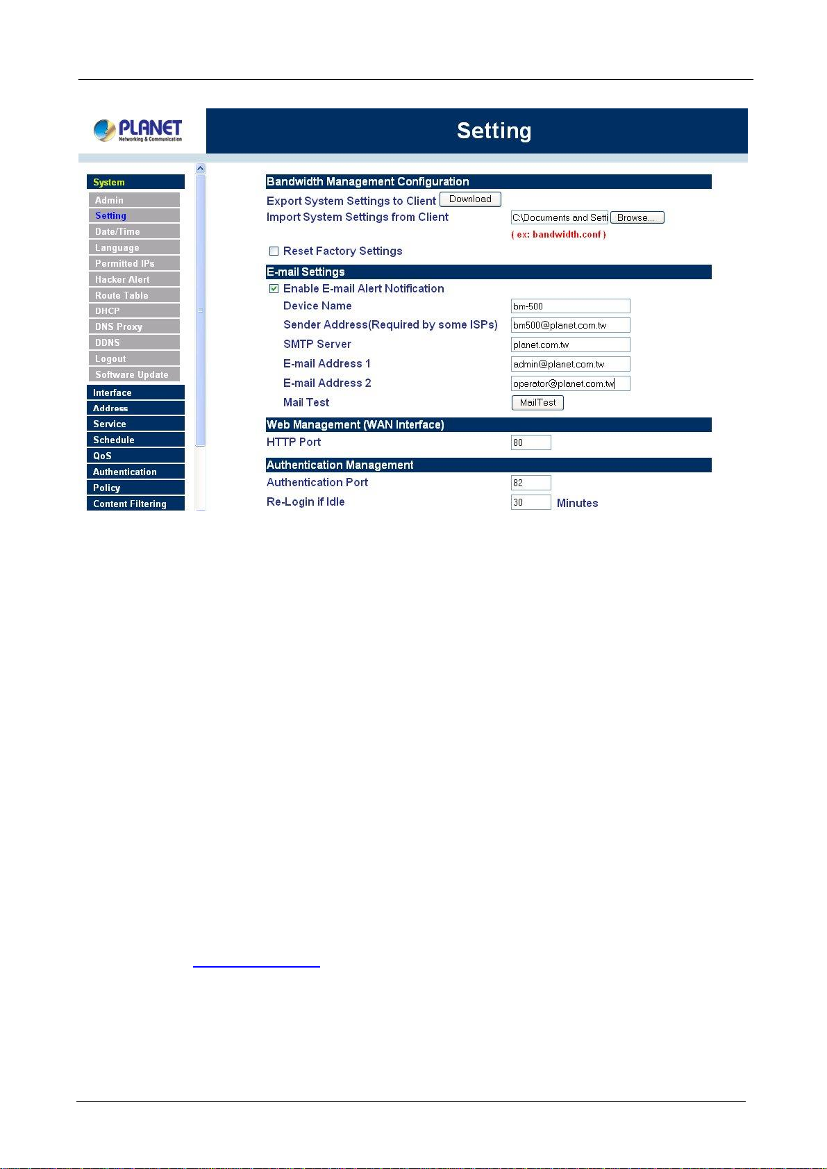
Enabling E-mail Alert Notification
Step 1. Select Enable E-mail Alert Notification under E-Mail Settings. This function will enable the
Bandwidth Management Gateway to send e-mail alerts to the System Administrator when the
network is being attacked by hackers or when emergency conditions occur.
Step 2. SMTP Server IP: Enter SMTP server’s IP address.
Step 3. E-Mail Address 1: Enter the first e-mail address to receive the alarm notification.
Step 4. E-Mail Address 2: Enter the second e-mail address to receive the alarm notification. (Optional)
Click OK on the bottom-right of the screen to enable E-mail alert notification.
- 19 -
Page 24
BM-500 Bandwidth Management Gateway User’s Manual
Web Management (WAN Interface) (Remote UI Management)
The administrator can change the port number used by HTTP port anytime. (Remote UI Management)
Step 1. Set Web Management (WAN Interface). The administrator can change the port number used
by HTTP port anytime.
Authentication
The administrator can specify the port number and authentication time of authentication management system
for LAN user to access WAN network. (Needs to setup authentication table in advance)
Authentication functions:
Authentication Port: The port number used for user login page. When user want to access WAN network
and the authentication (Policy -> Outgoing) is enabled, the user has to send http request with this port number.
The Bandwidth Management Gateway will send a User Login page for user to input user name and password.
For example, if the gateway IP address is 192.168.1.1 and authentication port is 82, user have to open a web
browser and input http://192.168.1.1:82 on the address file to have the user login page.
Re-Login if Idle: When the LAN user access to WAN network and do not use for a while, the connection will
be time-out. User has to re-login again. The default time is 30 minutes and you can configure this time by
“System”-> “Setting” page.
- 20 -
Page 25

BM-500 Bandwidth Management Gateway User’s Manual
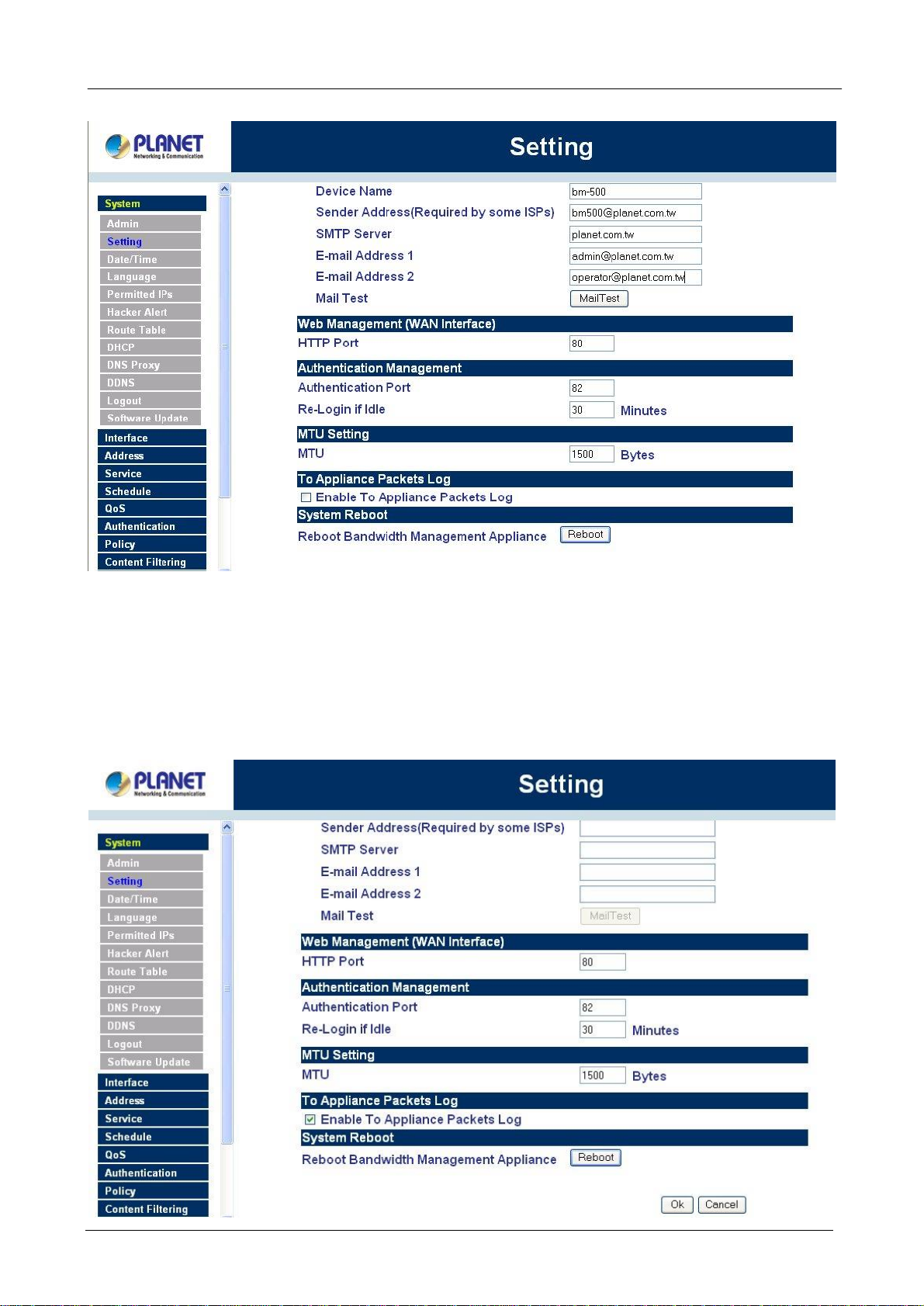
MTU (set networking packet length)
The administrator can modify the networking packet length.
Step 1. MTU Setting. Modify the networking packet length.
- 21 -
Page 26
BM-500 Bandwidth Management Gateway User’s Manual
To-Appliance Packets Log
Once this function is enabled, every packet to this appliance will be recorded for the administrator to trace.
Step 1. Select this option to the device’s To-Appliance Packets Log. Once this function is enabled,
every packet to this appliance will be recorded for system administrator to trace.
- 22 -
Page 27
BM-500 Bandwidth Management Gateway User’s Manual
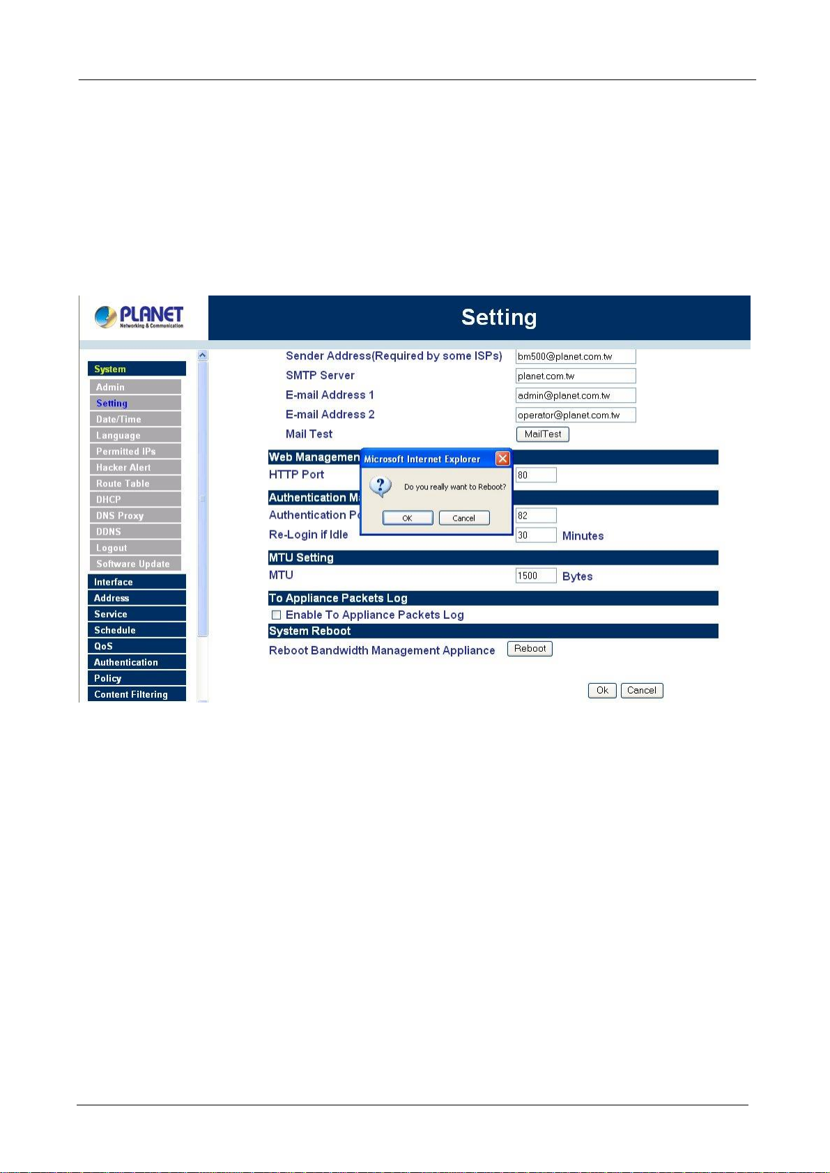
System Reboot
Once this function is enabled, the Bandwidth Management Gateway will be rebooted.
Reboot Bandwidth Management Gateway: Click Reboot.
A confirmation pop-up box will appear. Follow the confirmation pop-up box, click OK to restart Bandwidth
Management Gateway or click Cancel to discard changes
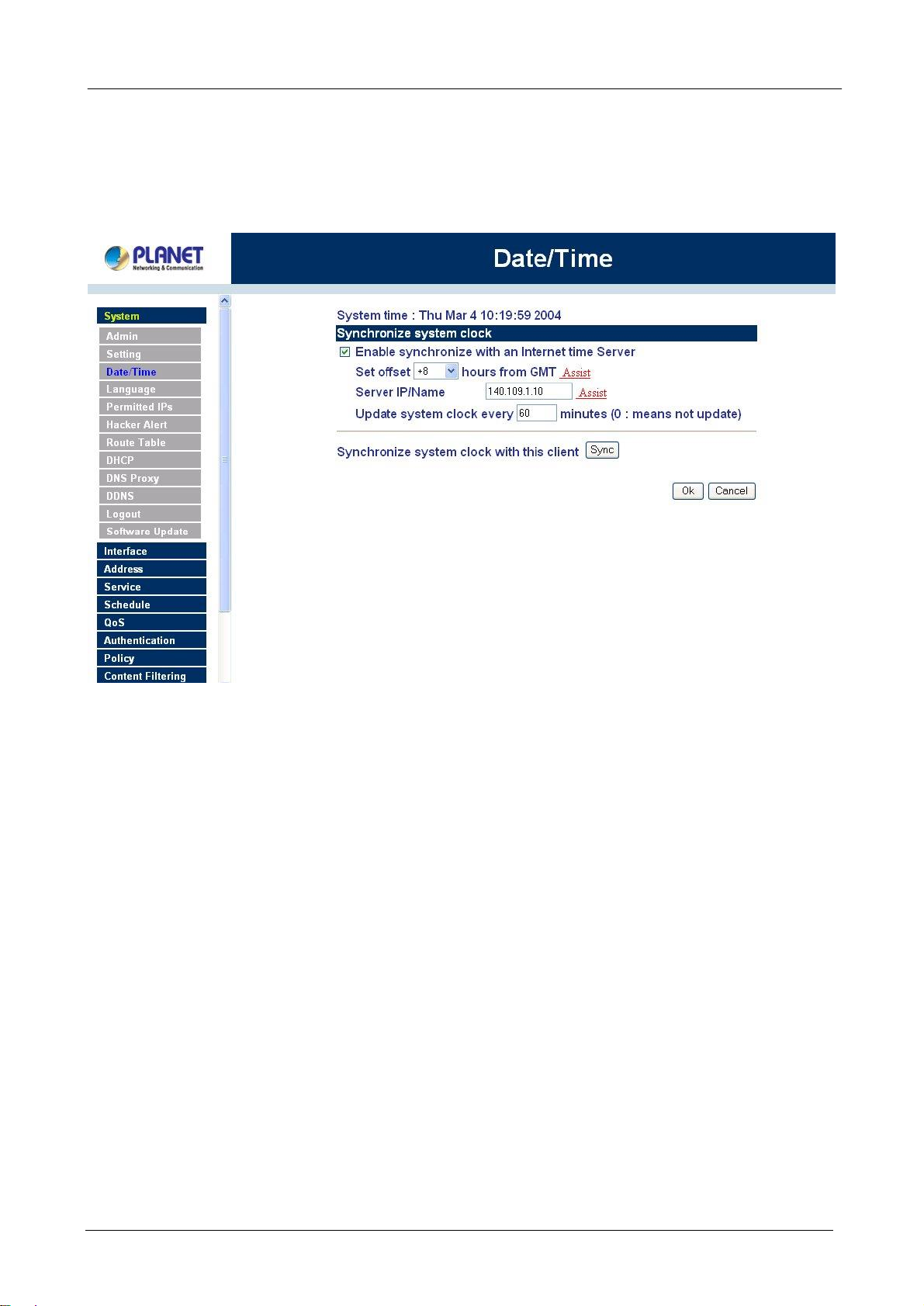
4.1.3 Date/Time
Synchronizing the Bandwidth Management Gateway with the System Clock
Administrator can configure the Bandwidth Management Gateway’s date and time by either syncing to an
Internet Network Time Server (NTP) or by syncing to your computer’s clock.
Follow these steps to sync to an Internet Time Server
Step 1. Enable synchronization by checking the box.
Step 2. Click the down arrow to select the offset time from GMT.
Step 3. Enter the Server IP Address or Server name with which you want to synchronize.
Step 4. Update system clock every 5 minutes You can set the interval time to synchronize with outside
servers. If you set it to 0, it means the device will not synchronize automatically.
- 23 -
Page 28
BM-500 Bandwidth Management Gateway User’s Manual
Follow this step to sync to your computer’s clock.
Step 1. Click on the Sync button.
Click OK to apply the setting or click Cancel to discard changes.
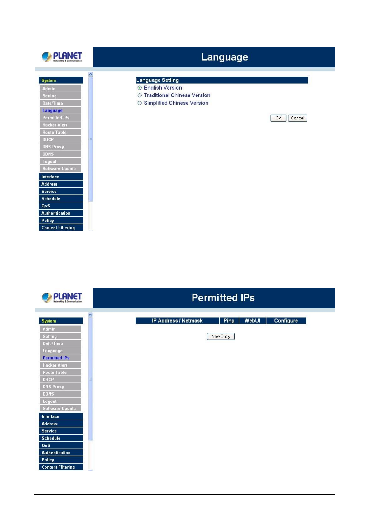
4.1.4 Language
Administrator can configure the Bandwidth Management Gateway Select the Language version
Step 1. Select the Language version (English Version, Traditional Chinese Version or Simplified
Chinese Version).
Step 2. Click 【OK】to set the Language version or click Cancel to discard changes.
- 24 -
Page 29
çç
BM-500 Bandwidth Management Gateway User’s Manual
4.1.5 Permitted IPs
Only the authorized IP address is permitted to manage the Bandwidth Management Gateway.
çç
- 25 -
Page 30
BM-500 Bandwidth Management Gateway User’s Manual
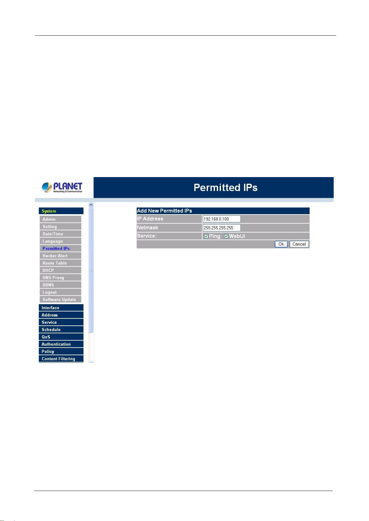
Add Permitted IP Address
Step 1. Click New Entry button.
Step 2. In IP Address field, enter the LAN IP address or WAN IP address.
n IP address: Enter the LAN IP address or WAN IP address.
n Netmask: Enter the netmask of LAN/WAN.
n Ping: Select this to allow the external network to ping the IP Address of the Firewall.
n WebUI: Check this item, Web User can use HTTP to connect to the Setting window of
BandWidth Management Gateway.
Step 3. Click OK to add Permitted IP or click Cancel to discard changes.
Modify Permitted IP Address
Step 1. In the table of Permitted IPs, highlight the IP you want to modify, and then click Modify.
Step 2. In Modify Permitted IP, enter new IP address.
Step 3. Click OK to modify or click Cancel to discard changes.
- 26 -
Page 31

BM-500 Bandwidth Management Gateway User’s Manual
Remove Permitted IP addresses
Step 1. In the table of Permitted IPs, highlight the IP you want to remove, and then click Remove.
Step 2. In Remove Permitted IP, enter new IP address.
Step 3. In the confirm window, click OK to remove or click Cancel to discard changes.
- 27 -
Page 32

BM-500 Bandwidth Management Gateway User’s Manual
4.1.6 Multiple NAT
Multiple NAT allows local port to set multiple subnetworks and connect with the Internet through different WAN
IP Addresses.
NOTE: This function is only available when the device is configured to NAT mode.
For instance, the lease line of a company applies several real IP Addresses 168.95.88.0/24, and the company is
divided into R&D department, service, sales department, procurement department, accounting department,
the company can distinguish each department by different subnetworks for the purpose of convenient
Management Gateway. The settings are as the following:
1.R&D department subnetwork: 192.168.1.11/24(Internal) ßà 168.95.88.253(WAN)
2. Service department subnetwork: 192.168.2.11/24(Internal) ßà 168.95.88.252(WAN)
3.Sales department subnetwork: 192.168.3.11/24(Internal) ßà 168.95.88.251(WAN)
4.Procurement department subnetwork 192.168.4.11/24(Internal) ßà 168.95.88.250(WAN)
5.Accounting department subnetwork 192.168.5.11/24(Internal) ßà 168.95.88.249(WAN)
The first department(R&D department) was set while setting interface IP, the other four ones have to be added
in Multiple NAT, after completing the settings, each department use the different WAN IP Address to connect
to the Internet. The settings of each department are as the following
Service IP Address: 192.168.2.1
Subnet Mask: 255.255.255.0
Default Gateway: 192.168.2.11
- 28 -
Page 33

BM-500 Bandwidth Management Gateway User’s Manual
The other departments are also set by groups, this is the function of Multiple NAT.
Multiple NAT settings
Step 1. Click Multiple NAT in the System menu to enter Multiple NAT window.
çç
External Interface IP: WAN port IP Address.
Alias IP of Int. Interface / Netmask: Local port IP Address and subnet Mask.
Configure: Modify the settings of Multiple NAT. Click Modify to modify the parameters of Multiple NAT or click
Delete to delete settings.
Add Multiple NAT
Step 1. Click the Add button below to add Multiple NAT.
Step 2. Enter the IP Address in the website name column of the new window.
n External interface IP Address: Select Global port IP Address.
n Alias IP of Internal Interface: Enter Local port IP Address.
n NetMask: Enter Local port subnet Mask.
Step 3. Click OK to add Multiple NAT or click Cancel to discard changes.
- 29 -
Page 34

BM-500 Bandwidth Management Gateway User’s Manual
Modify Multiple NAT
Step 1. Find the IP Address you want to modify and click Modify
Step 2. Enter the new IP Address in Modify Multiple NAT window.
Step 3. Click the OK button below to change the setting or click Cancel to discard changes.
Figure 1-22 Modify Multiple NAT
- 30 -
Page 35

BM-500 Bandwidth Management Gateway User’s Manual
Delete Multiple NAT
Step 1. Find the IP Address you want to delete and click Remove.
Step 2. A confirmation pop-up box will appear, click OK to delete the setting or click Cancel to discard
changes.
4.1.7 Hacker Alert
The Administrator can enable the device’s auto detect functions for hacker attackin this section. When
abnormal conditions occur, the Bandwidth Management Gateway will send an e-mail alert to notify the
Administrator, and also display warning messages in the Event window of Alarm.
- 31 -
Page 36

çç
BM-500 Bandwidth Management Gateway User’s Manual
Auto Detect functions
n Detect SYN Attack: Select this option to detect TCP SYN attacks that hackers send to
server computers continuously to block or cut down all the connections of the servers.
These attacks will prevent valid users from connecting to the servers. After enabling this
function, the System Administrator can enter the number of SYN packets per second that is
allowed to enter the network/Bandwidth Management Gateway. Once the SYN packets
exceed this limit, the activity will be logged in Alarm and an email alert is sent to the
Administrator. The default SYN flood threshold is set to 200 Pkts/Sec .
n Detect ICMP Flood: Select this option to detect ICMP flood attacks. When hackers
continuously send PING packets to all the machines of the LAN networks or to the
Bandwidth Management Gateway, your network is experiencing an ICMP flood attack.
This can cause traffic congestion on the network and slows the network down. After
enabling this function, the System Administrator can enter the number of ICMP packets per
second that is allowed to enter the network/Bandwidth Management Gateway. Once the
ICMP packets exceed this limit, the activity will be logged in Alarm and an email alert is sent
to the Administrator. The default ICMP flood threshold is set to 1000 Pkts/Sec.
n Detect UDP Flood: Select this option to detect UDP flood attacks. A UDP flood attack is
similar to an ICMP flood attack. After enabling this function, the System Administrator can
enter the number of UDP packets per second that is allow to enter the network/Bandwidth
Management Gateway. Once the UDP packets exceed this limit, the activity will be logged
- 32 -
Page 37

BM-500 Bandwidth Management Gateway User’s Manual
SYN on the TCP header is marked.
in Alarm and an email alert is sent to the Administrator. The default UDP flood threshold is
set to 1000 Pkts/Sec .
n Detect Ping of Death Attack: Select this option to detect the attacks of tremendous trash
data in PING packets that hackers send to cause System malfunction This attack can cause
network speed to slow down, or even make it necessary to restart the computer to get a
normal operation.
n Detect Tear Drop Attack : Select this option to detect tear drop attacks. These are
packets that are segmented to small packets with negative length. Some Systems treat the
negative value as a very large number, and copy enormous data into the System to cause
System damage, such as a shut down or a restart.
n Detect IP Spoofing Attack : Select this option to detect spoof attacks. Hackers disguise
themselves as trusted users of the network in Spoof attacks. They use a fake identity to try
to pass through the Bandwidth Management Gateway System and invade the network.
n Filter IP Source Route Option: Each IP packet can carry an optional field that specifies the
replying address that can be different from the source address specified in packet’s header.
Hackers can use this address field on disguised packets to invade LAN networks and send
LAN networks’ data back to them.
n Detect Port Scan Attack: Select this option to detect the port scans hackers use to
continuously scan networks on the Internet to detect computers and vulnerable ports that
are opened by those computers.
n Detect Land Attack : Some Systems may shut down when receiving packets with the same
source and destination addresses, the same source port and destination port, and when
Enable this function to detect such abnormal packets.
n Default Packet Deny: Denies all packets from passing the Bandwidth Management
Gateway. A packet can pass only when there is a policy that allows it to pass.
After enabling the needed detect functions, click OK to activate the changes.
4.1.8 Route Table
In this section, the Administrator can add static routes for the networks.
Entering the Route Table screen
Step 1. Click System on the left side menu bar, then click Route Table below it. The Route Table
window appears, in which current route settings are shown.
- 33 -
Page 38

çç
BM-500 Bandwidth Management Gateway User’s Manual
Route Table functions
n Interface: Destination network, LAN or WAN 1 networks.
n Destination IP: IP address of destination network.
n NetMask: Netmask of destination network.
n Gateway: Gateway IP address for connecting to destination network.
n Configure: Change settings in the route table.
Adding a new Static Route
Step 1. In the Route Table window, click the New Entry button.
Step 2. In the Add New Static Route window, enter new static route information.
Step 3. In the Interface field’s pull-down menu, choose the network to connect (LAN, WAN).
Step 4. Click OK to add the new static route or click Cancel to cancel.
- 34 -
Page 39

BM-500 Bandwidth Management Gateway User’s Manual
Modifying a Static Route:
Step 1. In the Route Table menu, find the route to edit and click the corresponding Modify option in the
Configure field.
Step 2. In the Modify Static Route window, modify the necessary routing addresses.
Step 3. Click OK to apply changes or click Cancel to cancel it.
- 35 -
Page 40

BM-500 Bandwidth Management Gateway User’s Manual
Removing a Static Route
Step 1. In the Route Table window, find the route to remove and click the corresponding Remove option
in the Configure field.
Step 2. In the Remove confirmation pop-up box, click OK to confirm removing or click Cancel to cancel
it.
- 36 -
Page 41

BM-500 Bandwidth Management Gateway User’s Manual
4.1.9 DHCP
In the section, the Administrator can configure DHCP (Dynamic Host Configuration Protocol) settings for the
LAN (LAN) network.
Entering the DHCP window
Click System on the left hand side menu bar, then click DHCP below it. The DHCP window appears in which
current DHCP settings are shown on the screen.
- 37 -
Page 42

çç
BM-500 Bandwidth Management Gateway User’s Manual
Dynamic IP Address functions
n Subnet: LAN network’s subnet
n NetMask: LAN network’s netmask
n Gateway: LAN network’s gateway IP address
n Broadcast: LAN network’s broadcast IP address
Enabling DHCP Support
Step 1. In the Dynamic IP Address window, click Enable DHCP Support.
Domain Name: The Administrator may enter the name of the LAN network domain if preferred.
DNS Server 1 : Enter the distributed IP address of DNS Server 1.
DNS Server 2 : Enter the distributed IP address of DNS Server 2.
WINS Server 1 : Enter the distributed IP address of WINS Server 1.
WINS Server 2 : Enter the distributed IP address of WINS Server 2.
Client IP Address Range 1: Enter the starting and the ending IP address dynamically assigning to
DHCP clients.
Client IP Address Range 2: Enter the starting and the ending IP address dynamically assigning to
DHCP clients. (Optional)
Step 2. Click OK to enable DHCP support.
- 38 -
Page 43

BM-500 Bandwidth Management Gateway User’s Manual
4.1.10 DNS Proxy
The Bandwidth Management Gateway’s Administrator may use the DNS Proxy function to make the
Bandwidth Management Gateway act as a DNS Server for the LAN and DMZ network. All DNS requests to
a specific Domain Name will be routed to the Bandwidth Management Gateway’s IP address. For example,
let’s say an organization has their mail server (i.e., mail.planet.com.tw) in the DMZ network (i.e.
192.168.10.10). The outside Internet world may access the mail server of the organization easily by its
domain name, providing that the Administrator has set up Virtual Server or Mapped IP settings correctly.
However, for the users in the LAN network, their WAN DNS server will assign them a public IP address for the
mail server. So for the LAN network to access the mail server (mail.planet.com.tw, they would have to go out
to the Internet, then come back through the Bandwidth Management Gateway to access the mail server.
Essentially, the LAN network is accessing the mail server by a real public IP address, while the mail server
serves their request by a NAT address and not a real one.
This odd situation occurs when there are servers in the DMZ network and they are bound to real IP addresses.
To avoid this, set up DNS Proxy so all the LAN network computers will use the Bandwidth Management
Gateway as a DNS server, which acts as the DNS Proxy.
If you want to use the DNS Proxy function of the device, the end user’s main DNS server IP address
should be the same IP Address as the device.
Click on System in the menu bar, then click on DNS Proxy below it. The DNS Proxy window will appear.
- 39 -
Page 44

BM-500 Bandwidth Management Gateway User’s Manual
Below is the information needed for setting up the DNS Proxy:
• Domain Name: The domain name of the server
• Virtual IP Address: The virtual IP address respective to DNS Proxy
• Configure: modify or remove each DNS Proxy policy
Adding a new DNS Proxy
Step 1: Click on the New Entry button and the Add New DNS Proxy window will appear.
Step 2: Fill in the appropriate settings for the domain name and virtual IP address.
Step 3: Click OK to save the policy or Cancel to cancel.
Modifying a DNS Proxy
Step 1: In the DNS Proxy window, find the policy to be modified and click the corresponding Modify option
in the Configure field.
Step 2: Make the necessary changes needed.
Step 3: Click OK to save changes or click on Cancel to cancel modifications.
Removing a DNS Proxy
Step 1: In the DNS Proxy window, find the policy to be removed and click the corresponding Remove
option in the Configure field.
Step 2: A confirmation pop-up box will appear, click OK to remove the DNS Proxy or click Cancel.
4.1.11 DDNS
The Dynamic DNS (require Dynamic DNS Service) allows you to alias a dynamic IP address to a static
hostname, allowing your device to be more easily accessed by specific name. When this function is enabled,
the IP address in Dynamic DNS Server will be automatically updated with the new IP address provided by
ISP.
- 40 -
Page 45

BM-500 Bandwidth Management Gateway User’s Manual
Click DDNS in the System menu to enter Dynamic DNS window.
The nouns in Dynamic DNS window:
!: Update Status, Connecting; Update succeed; Update fail; Unidentified error.
Domain name: Enter the password provided by ISP.
WAN IP Address: IP Address of the WAN port.
Modify: Modify dynamic DNS settings. Click Modify to change the DNS parameters; click Delete to delete the
settings.
How to use dynamic DNS:
The Bandwidth Management Gateway provides many service providers, users have to register prior to use
this function. For the usage regulations, see the providers’ websites.
How to register:
Firstly, Click Dynamic DNS in the System menu to enter Dynamic DNS window, then click Add button,on the
right side of the service providers, click Register, the service providers’ website will appear, please refer to
the website for the way of registration.
- 41 -
Page 46

BM-500 Bandwidth Management Gateway User’s Manual
Click to link to the website selected on the left.
Add Dynamic DNS settings
Step 1. Click Add button.
Step 2. Click the information in the column of the new window.
Service providers: Select service providers.
Register: to the service providers’ website.
WAN IP Address: IP Address of the WAN port.
¨ automatically fill in the WAN IP: Check to automatically fill in the WAN IP.。
User Name: Enter the registered user name.
Password: Enter the password provided by ISP(Internet Service Provider).
Domain name: Your host domain name provided by ISP.
Click OK to add dynamic DNS or click Cancel to discard changes.
- 42 -
Page 47

BM-500 Bandwidth Management Gateway User’s Manual
Modify dynamic DNS
Step 1. Find the item you want to change and click Modify.
Step 2. Enter the new information in the Modify Dynamic DNS window.
Click OK to change the settings or click Cancel to discard changes.。
- 43 -
Page 48

BM-500 Bandwidth Management Gateway User’s Manual
Remove Dynamic DNS
Step 1. Find the item you want to change and click Remove.
Step 2. A confirmation pop-up box will appear, click OK to delete the settings or click Cancel to discard
changes.
- 44 -
Page 49

BM-500 Bandwidth Management Gateway User’s Manual
4.1.12 Logout
Step 1. Select this option to the device’s Logout the Bandwidth Management Gateway. This function
protects your system while you are away.
Step 2. Click Logout the Bandwidth Management Gateway.
Step 3. Click OK to logout or click Cancel to discard the change.
- 45 -
Page 50

çç
BM-500 Bandwidth Management Gateway User’s Manual
4.1.13 Software Update
Under Software Update, the admin may update the device’s software with a newer software.
You may acquire the current version number of software in Version Number. Administrators may visit
distributor’s web site to download the latest version and save it in server’s hard disc.
Step 1. Click Browse to select the latest version of Software.
Step 2. Click OK to update software.
- 46 -
Page 51

çç
BM-500 Bandwidth Management Gateway User’s Manual
NOTE: It takes three minutes to update the software. The system will restart automatically after updating the
software.
- 47 -
Page 52

BM-500 Bandwidth Management Gateway User’s Manual
4.2 Interface
In this section, the Administrator can set up the IP addresses for the office network. The Administrator may
configure the IP addresses of the Internal (LAN) network, and the External (WAN) network. The netmask
and gateway IP addresses are also configured in this section.
Entering the Interface menu:
Step 1. Click on Configuration in the left menu bar.
Step 2. Then click on Interface below it. The current settings of the interface addresses will appear on
the screen.
LAN Interface
Using the Internal Interface, the Administrator sets up the Internal (LAN) network. The Internal network will
use a private IP scheme. The private IP network will not be routable on the Internet.
Transparent Mode: All the IP internetwork uses real IP.
NAT Mode: All the IP Internetwork uses NAT (Network Address Translation), which allows the private IP
internetworks use non-registered IP addresses to connect to the Internet.
IP Address: The private IP address of the Firewall’s internal network is the IP address of the Internal (LAN)
port of the Bandwidth Management Gateway. The default IP address is 192.168.1.1.
NOTE: The IP Address of Internal Interface and the DMZ Interface is a private IP address only.
If the new Internal IP Address is not 192.168.1.1, the Administrator needs to set the IP Address on the
computer to be on the same subnet as the Firewall and restart the System to make the new IP address
effective. For example, if the Firewall’s new Internal IP Address is 172.16.0.1, then enter the new Internal IP
Address 172.16.0.1 in the URL field of browser to connect to Firewall.
NetMask: This is the netmask of the internal network. The default netmask of the Bandwidth Management
Gateway is 255.255.255.0.
Ping: Select this to allow the internal network to ping the IP Address of the Firewall. If set to enable, the
Bandwidth Management Gateway will respond to ping packets from the internal network.
WebUI: Select this to allow the Bandwidth Management Gateway WEBUI to be accessed from the Internal
(LAN) network.
- 48 -
Page 53

çç
BM-500 Bandwidth Management Gateway User’s Manual
ADSL user Interface setting
PPPoE(External Interface)
Step 1. Select Interface function in the menu bar.
Step 2. Check the item PPPoE (ADSL User) below WAN Interface.
Step 3. Enter each parameter of WAN Interface.
çç
- 49 -
Page 54

BM-500 Bandwidth Management Gateway User’s Manual
For PPPoE (ADSL User): This option is for PPPoE users who are required to enter a username and
password in order to connect, such as ADSL users.
Current Status: Displays the current line status of the PPPoE connection.
IP Address: Displays the IP Address of the PPPoE connection
Username: Enter the PPPoE username provided by the ISP.
Password: Enter the PPPoE password provided by the ISP.
IP Address provided by ISP:
Dynamic: Select this if the IP address is automatically assigned by the ISP.
Fixed: Select this if you were given a static IP address. Enter the IP address that is given to you by your ISP.
Upload/Download Bandwidth: The bandwidth your ISP provided. (Maximum bandwidth for
Upload/Download Bandwidth is 10Mbps)
Service-On-Demand:
Auto Disconnect: The PPPoE connection will automatically disconnect after a length of idle time (no
activities). Enter in the amount of idle minutes before disconnection. Enter ‘0’ if you do not want the PPPoE
connection to disconnect at all.
Ping: Select this to allow the external network to ping the IP Address of the Firewall. This will allow people
from the Internet to be able to ping the Firewall. If set to enable, the Bandwidth Management Gateway will
respond to echo request packets from the external network.
WebUI: Select this to allow the Bandwidth Management Gateway WEBUI to be accessed from the External
(WAN) network. This will allow the WebUI to be configured from a user on the Internet. Keep in mind that
the Bandwidth Management Gateway always requires a username and password to enter the WebUI.
After completing the setting, click OK.
For Dynamic IP Address (Cable Modem User): This option is for users who are automatically assigned an
IP address by their ISP, such as cable modem users. The following fields apply:
IP Address: The dynamic IP address obtained by the Firewall from the ISP will be displayed here. This is
the IP address of the External (WAN) port of the Bandwidth Management Gateway.
MAC Address: This is the MAC Address of the Bandwidth Management Gateway.
User Name (Some ISPs may require): This is provided by your ISP.
Hostname: This will be the name assign to the Bandwidth Management Gateway. Some cable modem ISP
assign a specific hostname in order to connect to their network. Please enter the hostname here. If not
required by your ISP, you do not have to enter a hostname.
Max. Upstream/Downstream Bandwidth: The bandwidth provided by ISP. (Upstream/Downstream can be up
to 10Mbps)
Renew: Requests for receiving the new WAN IP address.
Release: Requests for releasing the obtained WAN IP address.
- 50 -
Page 55

BM-500 Bandwidth Management Gateway User’s Manual
Ping: Select this to allow the external network to ping the IP Address of the Firewall. This will allow people
from the Internet to be able to ping the Firewall. If set to enable, the Bandwidth Management Gateway will
respond to echo request packets from the external network.
WebUI: Select this to allow the Bandwidth Management Gateway WEBUI to be accessed from the External
(WAN) network. This will allow the WebUI to be configured from a user on the Internet. Keep in mind that
the Bandwidth Management Gateway always requires a username and password to enter the WebUI.
After setting all of the parameters, click OK button.
çç
For Static IP Address: This option is for users who are assigned a static IP Address from their ISP. Your
ISP will provide all the information needed for this section such as IP Address, Netmask, Gateway, and DNS.
Use this option if you have more than one public IP Address assigned to you.
IP Address: Enter the static IP address assigned to you by your ISP. This will be the public IP address of
the External (WAN) port of the Bandwidth Management Gateway.
Netmask: This will be the Netmask of the external (WAN) network. (i.e. 255.255.255.0)
Default Gateway: This will be the Gateway IP address.
DNS Server 1/2: Enter the DNS 1/2 server provided by ISP. (See Note.)
Max. Upstream Bandwidth / Max. Downstream Bandwidth: The bandwidth provided by ISP.
(Upstream/Downstream can be up to 10Mbps)
Ping: Select this to allow the external network to ping the IP Address of the Firewall. This will allow people
from the Internet to be able to ping the Firewall. If set to enable, the Bandwidth Management Gateway will
respond to echo request packets from the external network.
- 51 -
Page 56

BM-500 Bandwidth Management Gateway User’s Manual
WebUI: Select this to allow the Bandwidth Management Gateway WEBUI to be accessed from the External
(WAN) network. This will allow the WebUI to be configured from a user on the Internet. Keep in mind that
the Bandwidth Management Gateway always requires a username and password to enter the WebUI.
After setting all of the interface address, click OK button.
çç
If you want to set up DNS Server, you have to go to Virtual Server function to map the real IP address from
DNS server to the corresponding private IP address of internal DNS server. Enter the mapped IP address of
internal server in DNS server address field.
- 52 -
Page 57

BM-500 Bandwidth Management Gateway User’s Manual
4.3 Address
The Bandwidth Management Gateway allows the Administrator to set addresses of the LAN network, LAN
network group, WAN network, WAN group. These settings are to be used for policy editing.
What is the Address Table?
An IP address in the Address Table can be an address of a computer or a sub network. The Administrator can
assign an easily recognized name to an IP address. Based on the network it belongs to, an IP address can be
an LAN IP address, WAN IP address. If the Administrator needs to create a control policy for packets of
different IP addresses, he can first add a new group in the LAN Network Group or the WAN Network Group
and assign those IP addresses into the newly created group. Using group addresses can greatly simplify the
process of building control policies.
With easily recognized names of IP addresses and names of address groups shown in the address table, the
Administrator can use these names as the source address or destination address of control policies. The
address table should be built before creating control policies, so that the Administrator can pick the names of
correct IP addresses from the address table when setting up control policies.
How to use Address Table
With easily recognized names of IP addresses and names of address groups shown in the address table, the
Administrator can use these names as the source address or destination address of control policies. The
address table should be built before creating control policies, so that the Administrator can pick the names of
correct IP addresses from the address table when setting up control policies.
4.3.1 LAN
Entering the LAN window
Step 1. Click LAN under the Address menu to enter the LAN window. The current setting information
such as the name of the LAN network, IP and Netmask addresses will show on the screen.
- 53 -
Page 58

BM-500 Bandwidth Management Gateway User’s Manual
çç
Definition
Name: Name of LAN network address.
IP: IP address of LAN network
Netmask: Netmask of LAN network.
MAC Address: MAC address corresponded with LAN IP address.
Configure: You can configure the settings in LAN network. Click Modify to change the parameters in LAN
network. Click Remove to delete the settings.
In the LAN window, if one of the members has been added to Policy or LAN Group, the Configure column
will show the message – In Use. In this case, you are not allowed to modify or remove the setting.
Adding a new LAN Address
Step 1. In the LAN window, click the New Entry button.
Step 2. In the Add New Address window, enter the settings of a new LAN network address.
Step 3. Click OK to add the specified LAN network or click Cancel to cancel the changes.
- 54 -
Page 59

BM-500 Bandwidth Management Gateway User’s Manual
If you want to enable Add in Static DHCP function, enter the MAC Address then check the Add in Static
DHCP.
Modifying an LAN Address
Step 1. In the LAN window, locate the name of the network to be modified. Click the Modify option in
its corresponding Configure field. The Modify Address window appears on the screen
immediately.
Step 2. In the Modify Address window, fill in the new addresses.
Step 3. Click OK to save changes or click Cancel to discard changes.
- 55 -
Page 60

BM-500 Bandwidth Management Gateway User’s Manual
Removing a LAN Address
Step 1. In the LAN window, locate the name of the network to be removed. Click the Remove option in
its corresponding Configure field.
Step 2. In the Remove confirmation pop-up box, click OK to remove the address or click Cancel to
discard changes.
- 56 -
Page 61

BM-500 Bandwidth Management Gateway User’s Manual
4.3.2 LAN Group
Entering the LAN Group window
The LAN Addresses may be combined together to become a group.
Step 1. Click LAN Group under the Address menu to enter the LAN Group window. The current setting
information for the LAN network group appears on the screen.
çç
Definitions (LAN group):
Name: Name of the LAN group.
Member: Members of the group.
Configure: Configure the settings of LAN group. Click Modify to change the settings of LAN group. Click
Remove to delete the group.
In the LAN Group window, if one of the LAN Group has been added to Policy, the Configure column will
show the message – In Use. In this case, you are not allowed to modify or remove the LAN group. You have
to delete the Group in Policy window, and then you are allowed to configure the LAN Group.
Adding a LAN Group
- 57 -
Page 62

BM-500 Bandwidth Management Gateway User’s Manual
Step 1. In the LAN Group window, click the New Entry button to enter the Add New Address Group
window.
Step 2. In the Add New Address Group window:
n Available Address: list the names of all the members of the LAN network.
n Selected Address: list the names to be assigned to the new group.
n Name: enter the name of the new group in the open field.
Step 3. Add members: Select names to be added in Available Address list, and click the Add>> button
to add them to the Selected Address list.
Step 4. Remove members: Select names to be removed in the Selected Address list, and click the
<<Remove button to remove these members from Selected Address list.
Step 5. Click OK to add the new group or click Cancel to discard changes.
Modifying a LAN Group
Step 1. In the LAN Group window, locate the network group desired to be modified and click its
corresponding Modify option in the Configure field.
Step 2. A window displaying the information of the selected group appears:
n Available Address: list names of all members of the LAN network.
n Selected Address: list names of members which have been assigned to this group.
Step 3. Add members: Select names in Available Address list, and click the Add>> button to add
them to the Selected Address list.
Step 4. Remove members: Select names in the Selected Address list, and click the <<Remove
button to remove these members from the Selected Address list.
- 58 -
Page 63

BM-500 Bandwidth Management Gateway User’s Manual
Click OK to save changes or click Cancel to discard changes.
Figure3-7 Modify LAN Group
Removing a LAN Group
Step 1. In the LAN Group window, locate the group to be removed and click its corresponding Remove
option in the Configure field.
Step 2. In the Remove confirmation pop-up box, click OK to remove the group or click Cancel to
discard changes.
- 59 -
Page 64

BM-500 Bandwidth Management Gateway User’s Manual
4.3.3 WAN
Entering the WAN window
Step 1. Click WAN under the Address menu to enter the WAN window. The current setting
information, such as the name of the WAN network, IP and Netmask addresses will show on the
screen.
çç
- 60 -
Page 65

BM-500 Bandwidth Management Gateway User’s Manual
Definitions
Name: Name of WAN network address.
IP/Netmask: IP address/Netmask of WAN network.
Configure: Configure the settings of WAN network. Click Modify to change the settings of WAN network.
Click Remove to delete the setting of WAN network.
NOTE: In the WAN Network window, if one of the members has been added to Policy or LAN Group, the
Configure column will show the message – In Use. In this case you are not allowed to modify or remove the
settings.
Adding a new WAN Address
Step 1. In the WAN window, click the New Entry button.
Step 2. In the Add New Address window, enter the settings for a new WAN network address.
Step 3. Click OK to add the specified WAN network or click Cancel to discard changes.
Modifying an WAN Address
Step 1. In the WAN table, locate the name of the network to be modified and click the Modify option in
its corresponding Configure field.
Step 2. The Modify Address window will appear on the screen immediately. In the Modify Address
window, fill in new addresses.
- 61 -
Page 66

BM-500 Bandwidth Management Gateway User’s Manual
Step 3. Click OK to save changes or click Cancel to discard changes.
Removing an WAN Address
Step 1. In the WAN table, locate the name of the network to be removed and click the Remove option in
its corresponding Configure field.
Step 2. In the Remove confirmation pop-up box, click OK to remove the address or click Cancel to
discard changes.
- 62 -
Page 67

BM-500 Bandwidth Management Gateway User’s Manual
4.3.4 WAN Group
Entering the WAN Group window
Step 1. Click the WAN Group under the Address menu bar to enter the WAN window. The current
settings for the WAN network group(s) will appear on the screen.
çç
- 63 -
Page 68

BM-500 Bandwidth Management Gateway User’s Manual
Definitions:
Name: Name of the WAN group.
Member: Members of the group.
Configure: Configure the settings of WAN group. Click Modify to change the parameters of WAN group Click
Remove to delete the selected group.
NOTE: In the WAN Group window, if one of the members has been added to the Policy, “In Use” message
will appear in the Configure column. You are not allowed to modify or remove the settings. Go to the Policy
window to remove the setting, and then you can configure.
Adding an WAN Group
Step 1. In the WAN Group window, click the New Entry button and the Add New Address Group
window will appear.
Step 2. In the Add New Address Group window the following fields will appear:
n Name: enter the name of the new group.
n Available Address: List the names of all the members of the WAN network.
n Selected Address: List the names to assign to the new group.
n Add members: Select the names to be added in the Available Address list, and click the
Add>> button to add them to the Selected Address list.
n Remove members: Select the names to be removed in the Selected Address list, and click
the <<Remove button to remove them from the Selected Address list.
Step 3. Click OK to add the new group or click Cancel to discard changes.
- 64 -
Page 69

BM-500 Bandwidth Management Gateway User’s Manual
Modifying a WAN Group
Step 1. In the WAN Group window, locate the network group to be modified and click its corresponding
Modify button in the Configure field.
Step 2. A window displaying the information of the selected group appears:
n Available Address: list the names of all the members of the WAN network.
n Selected Address: list the names of the members that have been assigned to this group.
Step 3. Add members: Select the names to be added in the Available Address list, and click the
Add>> button to add them to the Selected Address list.
Step 4. Remove members: Select the names to be removed in the Selected Address list, and click the
<<Remove button to remove them from the Selected Address list.
Step 5. Click OK to save changes or click Cancel to discard changes.
Removing a WAN Group
Step 1. In the WAN Group window, locate the group to be removed and click its corresponding Modify
option in the Configure field.
Step 2. In the Remove confirmation pop-up box, click OK to remove the group or click Cancel to
discard changes.
- 65 -
Page 70

BM-500 Bandwidth Management Gateway User’s Manual
- 66 -
Page 71

BM-500 Bandwidth Management Gateway User’s Manual
4.4 Service
In this section, network services are defined and new network services can be added. There are three sub menus under
Service which are: Pre-defined, Custom, and Group. The Administrator can simply follow the instructions below to
define the protocols and port numbers for network communication applications. Users then can connect to servers and
other computers through these available network services.
What is Service?
TCP and UDP protocols support varieties of services, and each service consists of a TCP Port or UDP port number, such
as TELNET(23), SMTP(21), POP3(110),etc. The Bandwidth Management Gateway defines two services: pre-defined
service and custom service. The common-use services like TCP and UDP are defined in the pre-defined service and
cannot be modified or removed. In the custom menu, users can define other TCP port and UDP port numbers that are
not in the pre-defined menu according to their needs. When defining custom services, the client port ranges from 1024 to
65535 and the server port ranges from 0 to 1023.
How do I use Service?
The Administrator can add new service group names in the Group option under Service menu, and assign desired
services into that new group. Using service group the Administrator can simplify the processes of setting up control
policies. For example, there are 10 different computers that want to access 5 different services on a server, such as HTTP,
FTP, SMTP, POP3, and TELNET. Without the help of service groups, the Administrator needs to set up 50 (10x5) control
policies, but by applying all 5 services to a single group name in the service field, it takes only one control policy to
achieve the same effect as the 50 control policies.
4.4.1 Pre-defined
Entering a Pre-defined window
Step 1. Click Pre-defined under it. A window will appear with a list of services and their associated IP
addresses. This list cannot be modified.
- 67 -
Page 72

BM-500 Bandwidth Management Gateway User’s Manual
çç
Icons and Descriptions
Figur
Description
TCP services, i.g. FTP、FINGER、HTTP、、 HTTPS 、IMAP、SMTP、POP3、
ANY、AOL、BGP、GOPHER、InterLocator、IRC、L2TP、LDAP、NetMeeting、
NNTP、PPTPReal、 Media、RLOGIN、SSH、TCP ANY、TELNET、VDO Live、
WAIS、WINFRAME、X-WINDOWS, etc.
UDP services, i.g. IKE、DNS、NTP、IRC、RIP、SNMP、SYSLOG、TALK、
TFTP、UDP-ANY、UUC, etc.
ICMP services, i.g. PING、TRACEROUTE, etc.
4.4.2 Custom
Entering the Custom window
Step 1. Click Custom under it. A window will appear with a table showing all services currently defined
by the Administrator.
- 68 -
Page 73

çç
BM-500 Bandwidth Management Gateway User’s Manual
Figure 4-2 Custom Service
Definitions:
Service name: The defined service name.
Protocol: Network protocol used in the basic setting. Such as TCP、UDP or others.
Client port: The range of Client port in defined service.
If the number of ports entered in the two fields of Client port is different, it means that the port numbers
between these two numbers are opened. If the number of ports entered in the two fields of Client port is
identical, it means that the entered port number is opened.
Service port: The range of Service port in defined service.
If the number of ports entered in the two fields of Service port is different, it means that the port numbers
between these two numbers are opened. If the number of ports entered in the two fields of Service port is
identical, it means that the entered port number is opened.
Configure: Configure the settings in Service table. Click Modify to change the parameters in Service table.
Click Remove to delete the selected setting.
NOTE: In the Custom window, if one of the services has been added to Policy or Group, ”In Use” message
will appear in the Configure column. In this case you are not allowed to modify or remove the settings. Go to
the Policy or Group window to delete the setting, and then you can configure the settings.
Adding a new Service
In the Custom window, click the New Entry button and a new service table appears.
In the new service table:
- 69 -
Page 74

BM-500 Bandwidth Management Gateway User’s Manual
n New Service Name: This will be the name referencing the new service.
n Protocol: Enter the network protocol type to be used, such as TCP, UDP, or Other (please
enter the number for the protocol type).
n Client Port: enter the range of port number of new clients.
n Server Port: enter the range of port number of new servers.
The client port ranges from 1024 to 65535 and the server port ranges from 0 to 1023.
Step 1. Click OK to add new services, or click Cancel to cancel.
Step 2. Click OK to accept editing; or click Cancel.
Modifying Custom Services
Step 1. A table showing the current settings of the selected service appears on the screen
Step 2. Enter the new values.
Step 3. Click OK to accept editing; or click Cancel.
- 70 -
Page 75

BM-500 Bandwidth Management Gateway User’s Manual
Removing Custom Services
Step 1. Click its corresponding Remove option in the Configure field.
Step 2. In the Remove confirmation pop-up box, click OK to remove the selected service or click
Cancel to cancel action.
- 71 -
Page 76

BM-500 Bandwidth Management Gateway User’s Manual
4.4.3 Group
Accessing the Group window
Step 1. Click Group under it. A window will appear with a table displaying current service group
settings set by the Administrator.
çç
Definitions:
Group name: The Group name of the defined Service.
Service: The Service item of the Group.
Configure: Configure the settings of Group. Click Modify to change the parameters of the Group. Click
Remove to delete the Group.
NOTE: In the Group window, if one of the Service Groups has been added to Policy. “In Use” message will
appear in the Configure column. You are not allowed to modify or remove the settings. Go to the Policy
window, remove the Service group first, and then you are allowed to configure the setting.
Adding Service Groups
Step 1. In the Group window, click the New Entry button.
Step 2. In the Add Service Group window, the following fields will appear:
n Available Services: list all the available services.
n Selected Services: list services to be assigned to the new group.
Step 3. Enter the new group name in the group Name field. This will be the name referencing the
created group.
- 72 -
Page 77

BM-500 Bandwidth Management Gateway User’s Manual
Step 4. To add new services: Select the services desired to be added in the Available Services list
and then click the Add>> button to add them to the group.
Step 5. To remove services: Select services desired to be removed in the Available Services, and
then click the <<Remove button to remove them from the group.
Step 6. Click OK to add the new group.
Modifying Service Groups
Step 1. In the Mod (modify) group window the following fields are displayed:
n Available Services: lists all the available services.
n Selected Services: list services that have been assigned to the selected group.
Step 2. Add new services: Select services in the Available Services list, and then click the Add>>
button to add them to the group.
Step 3. Remove services: Select services to be removed in the Selected Services list, and then click
the <<Remove button to remove theses services from the group.
Step 4. Click OK to save editing changes.
- 73 -
Page 78

BM-500 Bandwidth Management Gateway User’s Manual
Removing Service Groups
In the Remove confirmation pop-up box, click OK to remove the selected service group or click Cancel to
cancel removing.
- 74 -
Page 79

BM-500 Bandwidth Management Gateway User’s Manual
4.5 Schedule
The Bandwidth Management Gateway allows the Administrator to configure a schedule for policies to take
affect. By creating a schedule, the Administrator is allowing the Bandwidth Management Gateway policies to
be used at those designated times only. Any activities outside of the scheduled time slot will not follow the
Bandwidth Management Gateway policies therefore will likely not be permitted to pass through the Bandwidth
Management Gateway. The Administrator can configure the start time and stop time, as well as creating 2
different time periods in a day. For example, an organization may only want the Bandwidth Management
Gateway to allow the LAN network users to access the Internet during work hours. Therefore, the
Administrator may create a schedule to allow the Bandwidth Management Gateway to work Monday-Friday,
8AM - 5PM only. During the non-work hours, the Bandwidth Management Gateway will not allow Internet
access.
Accessing the Schedule window
Step 1. Click on Schedule on the menu bar and the schedule window will appear displaying the active
schedules.
çç
The following items are displayed in this window:
Name: the name assigned to the schedule
Comment: a short comment describing the schedule
Configure: modify or remove
- 75 -
Page 80

BM-500 Bandwidth Management Gateway User’s Manual
Adding a new Schedule
Step 1. Click on the New Entry button and the Add New Schedule window will appear.
n Schedule Name: Fill in a name for the new schedule.
n Period 1: Configure the start and stop time for the days of the week that the schedule will
be active.
Step 2. Click OK to save the new schedule or click Cancel to cancel adding the new schedule.
NOTE: In setting a Schedule, the value in Start time must be less than the value in Stop Time, or you cannot
add or configure the setting.
Modifying a Schedule
Step 1. In the Schedule window, find the policy to be modified and click the corresponding Modify
option in the Configure field. Make needed changes.
Step 2. Click OK to save changes.
- 76 -
Page 81

BM-500 Bandwidth Management Gateway User’s Manual
Removing a Schedule
Step 1. In the Schedule window, find the policy to be removed and click the corresponding Remove
option in the Configure field.
Step 2. A confirmation pop-up box will appear, click on OK to remove the schedule.
- 77 -
Page 82

BM-500 Bandwidth Management Gateway User’s Manual
4.6 QoS
By configuring the QoS, you can control the outbound Upstream/downstream Bandwidth.
The administrator can configure the bandwidth according to the WAN bandwidth.
Downstream Bandwidth: To configure the Guaranteed Bandwidth and Maximum Bandwidth.
Upstream Bandwidth: To configure the Guaranteed Bandwidth and Maximum Bandwidth.
QoS Priority: To configure the priority of distributing Upstream/Downstream and unused bandwidth.
The Bandwidth Management Gateway configures the bandwidth by different QoS , and selects the suitable
QoS through Policy to control and efficiently distribute bandwidth. The Bandwidth Management Gateway also
makes it convenient for the administrator to use the Bandwidth Management Gateway with the best Utility.
Configuration of QoS
Click QoS in the menu bar on the left hand side.
çç
Definitions:
Name: The name of the QoS you want to configure.
Downstream Bandwidth: To configure the Guaranteed Bandwidth and Maximum Bandwidth.
Upstream Bandwidth: To configure the Guaranteed Bandwidth and Maximum Bandwidth.
QoS Priority: To configure the priority of distributing Upstream/Downstream and unused bandwidth.
Add New QoS
Step 1. Click QoS in the menu bar on the left hand side.
- 78 -
Page 83

BM-500 Bandwidth Management Gateway User’s Manual
Step 2. Click the New Entry button to add new QoS.
Definition
Name: The name of the QoS you want to configure.
Downstream Bandwidth: To configure the Guarateed Bandwidth and Maximum Bandwidth.
Upstream Bandwidth: To configure the Guarateed Bandwidth and Maximum Bandwidth.
QoS Priority: To configure the priority of distrubuting Upstream/Downstream and unused
bandwidth.
Click the OK button to add new QoS.
Modify QoS
Step 1. Click QoS in the menu bar on the left hand side.
- 79 -
Page 84

BM-500 Bandwidth Management Gateway User’s Manual
Click the Modify button to modify QoS.
Definition:
Name: The name of the QoS you want to configure.
Downstream Bandwidth: To configure the Guarateed Bandwidth and Maximum Bandwidth.
Upstream Bandwidth: To configure the Guarateed Bandwidth and Maximum Bandwidth.
QoS Priority: To configure the priority of distrubuting Upstream/Downstream and unused bandwidth.
Click the OK button to modify QoS.
Delete QoS
Step 1. In the QoS window, find the QoS you want to change, and click Delete in the Configure column.
Step 2. In the Delete QoS window, click OK to delete the QoS or click Cancel to discard the change.
- 80 -
Page 85

BM-500 Bandwidth Management Gateway User’s Manual
- 81 -
Page 86

BM-500 Bandwidth Management Gateway User’s Manual
4.7 Authentication
By configuring the Authentication, you can control the user’s access right time of LAN to WAN. The
administrator can configure the authentication according to the authentication account and password.
The Bandwidth Management Gateway configures the authentication of LAN’s user by setting account and
password to identify the privilege.
Configuration of Authentication
Click Authentication in the menu bar on the left hand side.
Definitions:
User Name: The name of the authentication user you want to configure.
Configure: modify settings or remove the user account.
Adding a new Auth User
Step 1. In the Authentication window, click the New User button to create a new Authentication.
Step 2. In the Add New User window:
n User Name: enter the username of new Authentication.
n Password: enter a password for the new Authentication.
n Confirm Password: enter the password again.
Step 3. Click OK to add the user or click Cancel to cancel the addition.
- 82 -
Page 87

BM-500 Bandwidth Management Gateway User’s Manual
NOTE: When the LAN user access to WAN network and do not use for a while, the connection will be
time-out. User has to re-login again. The default time is 30 minutes and you can configure this time by
“System”-> “Setting” page.
In the form of controlling the [Outgoing] Policy, enable the Authentication-User Function.
- 83 -
Page 88

BM-500 Bandwidth Management Gateway User’s Manual
When the user’s idle time exceed the “Re-Login If Idle” time and the user wan to connect to WAN, the
authentication web page will be shown again or user need to manually input the login page. Once user
enters the correct user name and password, he can access the WAN resource again.
User Login Page Definitions:
n User Name: The name of the Authentication you want to configure.
n Password: The input carries on the authentication the password
Modifying the Authentication User
Step 1. In the Authentication window, locate the User name you want to edit, and click on Modify in the
Configure field.
Step 2. The Modify Auth-User Password window will appear. Enter in the required information:
n Auth-User: show original authentication user.
n Password: show original password.
n New Password: enter new password
n Confirm Password: enter the new password again.
Step 3. Click OK to confirm authentication user change or click Cancel to cancel it.
- 84 -
Page 89

BM-500 Bandwidth Management Gateway User’s Manual
Removing a Authentication User
Step 1. In the Authentication table, locate the user name you want to remove, and click on the Remove
option in the Configure field.
Step 2. The Remove confirmation pop-up box will appear.
Step 3. Click OK to remove that Authentication User or click Cancel to cancel.
- 85 -
Page 90

BM-500 Bandwidth Management Gateway User’s Manual
4.8 Policy
This section provides the Administrator with facilities to sent control policies for packets with different source
IP addresses, source ports, destination IP addresses, and destination ports. Control policies decide whether
packets from different network objects, network services, and applications are able to pass through the
Bandwidth Management Gateway.
What is Policy?
The device uses policies to filter packets. The policy settings are: source address, destination address,
services, permission, packet log, packet statistics, and flow alarm. Based on its source addresses, a packet
can be categorized into:
(1) Outgoing: a client is in the LAN networks, while a server is in the WAN networks.
(2) Incoming, a client is in the WAN networks, while a server is in the LAN networks.
How do I use Policy?
The policy settings are source addresses, destination addresses, services, permission, log, statistics, and
flow alarm. Among them, source addresses, destination addresses and IP mapping addresses have to be
defined in the Address menu in advance. Services can be used directly in setting up policies, if they are in the
Pre-defined Service menu. Custom services need to be defined in the Custom menu before they can be used
in the policy settings.
If the destination address of an incoming policy is a Mapped IP address or a Virtual Server address, then the
address has to be defined in the Virtual Server section instead of the Address section.
4.8.1 Outgoing
This section describes steps to create policies for packets and services from the LAN network to the WAN
network.
Entering the Outgoing window
Step 1. Click Policy on the left hand side menu bar,
Step 2. Click Outgoing under it. A window will appear with a table displaying currently defined
Outgoing policies.
- 86 -
Page 91

çç
BM-500 Bandwidth Management Gateway User’s Manual
The fields in the Outgoing window are:
n Source: source network addresses that are specified in the LAN section of Address menu,
or all the LAN network addresses.
n Destination: destination network addresses that are specified in the WAN section of the
Address menu, or all of the WAN network addresses.
n Service: specify services provided by WAN network servers.
n Action: control actions to permit or reject/deny packets from LAN networks to WAN network
travelling through the Bandwidth Management Gateway.
n Option: specify the monitoring functions on packets from LAN networks to WAN networks
travelling through the Bandwidth Management Gateway.
n Configure: modify settings.
n Move: this sets the priority of the policies, number 1 being the highest priority.
Descriptions for Policy figures:
Figure Name Description
Permit
Permit the specified packets from LAN network to WAN
network.
Block
Log Traffic and event log function is enabled.
Statistics Flow statistics function is enabled.
Schedule
Block the specified packets from LAN network to WAN
network.
The automatic execution function in Schedule table has
been enabled.
- 87 -
Page 92

BM-500 Bandwidth Management Gateway User’s Manual
function in the menu bar on the left
function in the menu bar on the left
function automatically in a
Remarks:
To view the traffic and event log of the system, click Log function in the menu bar on
the left hand side.
To view the alarm records of the system, click Alarm
hand side.
To view the statistics of the system, click Statistics
hand side.
Bandwidth Management Gateway can execute the schedule
certain time and range. To modify the schedule, click the Schedule function in the menu
baron the left hand side.
Bandwidth Management Gateway can execute the QoS function function automatically.
To modify the QoS, click the QoS function in the menu bar on the left hand side.
Alarm Threshold Traffic and event alarm function is enabled.
QoS QoS function is enabled.
Adding a new Outgoing Policy
Click on the New Entry button and the Add New Policy window will appear.
Source Address: Select the name of the LAN network from the drop down list. The drop down list contains
the names of all LAN networks defined in the LAN section of the Address menu. To create a new source
address, please go to the LAN section under the Address menu.
- 88 -
Page 93

BM-500 Bandwidth Management Gateway User’s Manual
Destination Address: Select the name of the WANnetwork from the drop down list. The drop down list
contains the names of all WAN networks defined in the WANsection of the Address window. To create a new
destination address, please go to the WANsection under the Address menu.
Service: Specified services provided by WANnetwork servers. These are srvices/application that are
allowed to pass from the LAN network to the WANnetwork. Choose ANY for all services.
Action: Select Permit or Deny from the drop down list to allow or reject the packets travelling between the
source network and the destination network.
Logging: Select Enable to enable flow monitoring.
Statistics: Select Enable to enable flow statistics.
Schedule: Select the pre-defined schedule name from the pull-up menu. The policy will be executed in the
specific time slot automatically.
Alarm Threshold: set a maximum flow rate (in Kbytes/Sec). An alarm will be sent if flow rates are higher
than the specified value.
QoS: To determine if the QoS function can work in this Policy function.
Click OK to add a new outgoing policy; or click Cancel to cancel adding a new outgoing policy.
To change the Policy order of Outgoing, select the number from the pull-down menu on the right hand side
Move column
Modifying an Outgoing policy
Step 1. In the Modify Policy window, fill in new settings.
NOTE: To change or add selections in the drop-down list for source or destination address, go to the section where
the selections are setup. (Source Address→LAN of Address menu; Destination Address → WAN of Address menu;
Service→[Pre-defined],[Custom] or Group under Service).
Click OK to do confirm modification or click Cancel to cancel it.
- 89 -
Page 94

BM-500 Bandwidth Management Gateway User’s Manual
Source Address: Select the name of LAN from the pull-down menu.
The names of LAN listed in this pull-down menu are: the Source Addresses that are already set.
Destination Address: Select the name of WAN from the pull-down menu.
The names of WAN listed in this pull-down menu are: the Destination Addresses that are already set IP
address of WAN network.
Service: Select the service item from the pull-down menu
Action: Select Permit or Block to allow or reject the specified packets from LAN network to WAN network.
Logging: Select Enable to enable the Logging function.
Statistics: Select Enable to enable the Statistics function.
Schedule: Select the item listed in the schedule to enable the policy to automatically execute the function in a
certain time and range.
Alarm Threshold: To set the maximum value of transmitting and receiving packet, enter the number based
on the unit(KBytes/Sec)
QoS: To determine if the QoS function can work in this Policy function.
Click OK to execute the new setting or click Cancel to discard changes.
NOTE: If you want to change or add new items in the pull-down menu, go to the corresponding chapter for
setup.
Source Address: LAN of Address menu
Destination Address: WAN of Address menu
- 90 -
Page 95

BM-500 Bandwidth Management Gateway User’s Manual
Removing the Outgoing Policy
Step 1. In the Remove confirmation dialogue box, click OK to remove the policy or click Cancel to
cancel removing.
4.8.2 Incoming
This chapter describes steps to create policies for packets and services from the WAN network to the LAN
network including Mapped IP and Virtual Server.
Enter Incoming window
Step 1. Click Incoming under the Policy menu to enter the Incoming window. The Incoming table will
display current defined policies from the WAN network to assigned Mapped IP or Virtual Server.
- 91 -
Page 96

çç
BM-500 Bandwidth Management Gateway User’s Manual
Definition (Incoming):
No.: The numbering of the selected Policy, starting with Number 1.
Source Address: The WAN address was selected in WAN function of the Address Table.
Destination Address: The mapped IP or Virtual Server IP configured in the Mapped IP or Virtual Server
1/2/3/4 window under Virtual Server function.
Service: The service item provided by Virtual Server (or Mapped IP).
Action: Control actions to permit or reject packets from LAN networks to WAN network or Virtual Server
(Mapped IP) traveling through the Bandwidth Management Gateway.
Option: Control actions to monitor packets from WAN network or Virtual Server (Mapped IP) traveling through
the Bandwidth Management Gateway. The first column is the logging function. The second column is the
Statistics function. The third column is the Schedule function. The fourth column is the Alarm Threshold
function. The fifth column is the QoS function. If the figures appear in the column, it means that the function is
enabled. On the other hand, if there is no figures appeared in the column, it means that the function is not
enabled.
The fields of the Incoming window are:
n Source: source networks which are specified in the WAN section of the Address menu, or
all the WAN network addresses.
n Destination: destination networks, which are IP Mapping addresses or Virtual server
network addresses created in Virtual Server menu.
n Service: services supported by Virtual Servers (or Mapped IP).
n Action: control actions to permit or deny packets from WAN networks to Virtual
Server/Mapped IP travelling through the device.
- 92 -
Page 97

n Option: specify the monitoring functions on packets from WAN networks to Virtual
function in the menu bar on the left
function in the menu bar on the left
To modify the schedule, click the
Schedule
function in the menu bar.
Server/Mapped IP travelling through the Bandwidth Management Gateway.
n Configure: modify settings or remove incoming policy.
n Move: this sets the priority of the policies, number 1 being the highest priority.
Descriptions for Policy figures:
Figure Name Description
BM-500 Bandwidth Management Gateway User’s Manual
Remarks:
To view the traffic and event log of the system, click Log function in the menu bar on
the left hand side.
To view the alarm records of the system, click Alarm
hand side.
To view the statistics of the system, click Statistics
hand side.
Permit Permit the specified packets from WAN to LAN.
Block the specified packets from WAN network to LAN
Block
network.
Log Traffic and event log function is enabled.
Statistics Flow statistics function is enabled.
The automatic execution function in Schedule table has
Schedule
been enabled.
Alarm Threshold Traffic and event alarm function is enabled.
QoS QoS function is enabled.
Bandwidth Management Gateway can execute the schedule in time slot automatically.
Adding an Incoming Policy
Under Incoming of the Policy menu, click the New Entry button.
- 93 -
Page 98

BM-500 Bandwidth Management Gateway User’s Manual
Source Address: Select the name of WAN from the pull-down menu.
The names of WAN listed in this pull-down menu are: the Source Addresses that are already set. If you want
to add new WAN addresses to WAN of address menu, you have to go to WAN function window to configure;
you will not be able to add new WAN addresses here.
Destination Address: Select the name of LAN from the pull-down menu.
The names of LAN listed in this pull-down menu are: The Mapped IP or Server Virtual IP configured in the
Mapped IP or Virtual Server 1/2/3/4 window under Virtual Server function. To add new items into the pull-down
menu, go to Virtual Server window to configure.
Service: Select the service item from the pull-down menu.
Action: Select from the pull-down menu to determine the WAN, Virtual Server(or Mapped IP) packets are
permitted or forbidden to pass. Select Permit or Forbid.
Logging: Select Enable to enable the Logging function.
Statistics: Select Enable the enable the Statistics function.
Schedule: Select the item listed in the schedule to enable the policy to automatically execute the function in a
certain time and range.
Alarm Threshold: To set the maximum value of transmitting and receiving packet, enter the number based
on the unit(KBytes/Sec)
QoS: To determine if the QoS function can work in this Policy function.
- 94 -
Page 99

BM-500 Bandwidth Management Gateway User’s Manual
Click OK to execute the new setting or click Cancel to discard changes.
NOTE: To change the Policy order of Incoming, select the number from the pull-down menu on the right hand
side Move column
Modifying Incoming Policy
Step 1. In the Modify Policy window, fill in new settings.
Step 2. Click OK to save modifications or click Cancel to cancel modifications.
Source Address: Select the name of WAN from the pull-down menu.
The names of WAN listed in this pull-down menu are: the Source Addresses that are already set. If you want
to add new WAN addresses to WAN of address menu, you have to go to WAN function window to configure;
you will not be able to add new WAN addresses here.
Destination Address: Select the name of LAN from the pull-down menu.
The names of LAN listed in this pull-down menu are: The Mapped IP or Server Virtual IP configured in the
Mapped IP or Virtual Server 1/2/3/4 window under Virtual Server function. To add new items into the pull-down
menu, go to Virtual Server window to configure.
Service: Select the service item from the pull-down menu.
Action: Select from the pull-down menu to determine the WAN, Virtual Server(or Mapped IP) packets are
permitted or forbidden to pass. Select Permit or Forbid.
Logging: Select Enable to enable the Logging function.
Statistics: Select Enable the enable the Statistics function.
Schedule: Select the item listed in the schedule to enable the policy to automatically execute the function in a
- 95 -
Page 100

BM-500 Bandwidth Management Gateway User’s Manual
certain time and range.
Alarm Threshold: To set the maximum value of transmitting and receiving packet, enter the number based
on the unit(KBytes/Sec)
QoS: To determine if the QoS function can work in this Policy function.
Click OK to execute the new setting or click Cancel to discard changes.
NOTE: if you want to change or add new items into the pull-down menu, go to the original configuration unit.
Removing an Incoming Policy
Step 1. In the Remove confirmation window, click Ok to remove the policy or click Cancel to cancel
removing.
This chapter introduces how to configure the Bandwidth Management Gateway to effectively control your
bandwidth usage.
On the top of the Web interface, there is three major menu of the bandwidth Management Gateway:
System Settings: The basic system configurations
Policy Editor: The policy that will be used to manage the bandwidth
Report: The reporting system of the bandwidth Management Gateway base on the system settings
and pre-defined policy
The bandwidth Management Gateway will need the three parameters before it operates the bandwidth control:
Host, (illustrated in section 4.1.6), Services (illustrated in section 4.1.7) and Policy, (illustrated in section 4.2).
However, some of the configurations are also required. Please refer to the related section for the details.
- 96 -
 Loading...