

Page 1

2Mbps Bandwidth Manager
BM-2002
User’s Manual
Page 2

BM-2002 Bandwidth Manager User’s Manual
Copyright
Copyright (C) 2003 PLANET Technology Corp. All rights reserved.
The products and programs described in this User’s Manual are licensed products of PLANET Technology, This User’s
Manual contains proprietary information protected by copyright, and this User ’s Manual and all accompanying hardware,
software, and documentation are copyrighted.
No part of this User’s Manual may be copied, photocopied, reproduced, translated, or reduced to any electronic medium
or machine-readable form by any means by electronic or mechanical. Including photocopying, recording, or information
storage and retrieval systems, for any purpose other than the purchaser's personal use, and without the prior express
written permission of PLANET Technology.
Disclaimer
PLANET Technology does not warrant that the hardware will work properly in all environments and applications, and
makes no warranty and representation, either implied or expressed, with respect to the quality, performance,
merchantability, or fitness for a particular purpose.
PLANET has made every effort to ensure that this User’s Manual is accurate; PLANET disclaims liability for any
inaccuracies or omissions that may have occurred.
Information in this User’s Manual is subject to change without notice and does not represent a commitment on the part of
PLANET. PLANET assumes no responsibility for any inaccuracies that may be contained in this User’s Manual. PLANET
makes no commitment to update or keep current the information in this User ’s Manual, and reserves the right to make
improvements to this User’s Manual and/or to the products described in this User ’s Manual, at any time without notice.
If you find information in this manual that is incorrect, misleading, or incomplete, we would appreciate your comments and
suggestions.
CE mark Warning
This is a class A device, In a domestic environment, this product may cause radio interference, in which case the user may
be required to take adequate measures.
Trademarks
The PLANET logo is a trademark of PLANET Technology.
This documentation may refer to numerous hardware and software products by their trade names. In most, if not all cases,
these designations are claimed as trademarks or registered trademarks by their respective companies.
Customer Service
For information on customer service and support for the Bandwidth Manager, please refer to the following Website URL:
http://www.planet.com.tw
Before contacting customer service, please take a moment to gather the following information:
¨ Bandwidth Manager serial number and MAC address
¨ Any error messages that displayed when the problem occurred
¨ Any software running when the problem occurred
¨ Steps you took to resolve the problem on your own
Revision
User’s Manual for PLANET BM-2002
Model: BM-2002
Rev: 2.0 (May, 2003)
Part No. EM-BM2002v2
Page 3

BM-2002 Bandwidth Manager User’s Manual
Table of Contents
CHAPTER 1:INTRODUCTION........................................................................................................................1
1.1 FEATURES .................................................................................................................................................1
1.2 PACKAGE CONTENTS..................................................................................................................................1
1.3 BANDWIDTH MANAGER FRONT VIEW ...........................................................................................................2
1.4 BANDWIDTH MANAGER REAR PANEL ...........................................................................................................3
1.5 SPECIFICATION...........................................................................................................................................4
CHAPTER 2:HARDWARE INSTALLATION...................................................................................................5
2.1 INSTALLATION REQUIREMENTS ....................................................................................................................5
2.2 DEPLOY BANDWIDTH MANAGER ON THE NETWORK .....................................................................................5
2.3 INSTALL BANDWIDTH MANAGER TO YOUR NETWORK....................................................................................6
CHAPTER 3:GETTING STARTED.................................................................................................................7
3.1 CONFIGURATION ON A CLIENT SIDE TO LINK WITH BANDWIDTH MANAGER.....................................................7
3.2 LOGGING IN AS ADMINISTRATOR..................................................................................................................9
CHAPTER 4:WEB CONFIGURATION..........................................................................................................11
4.1 SYSTEM SETTINGS ...................................................................................................................................11
4.1.1 Information......................................................................................................................................11
4.1.2 Network..........................................................................................................................................12
4.1.3 Bandwidth.......................................................................................................................................12
4.1.4 Date/Time.......................................................................................................................................13
4.1.5 Host................................................................................................................................................13
4.1.6 Service............................................................................................................................................15
4.1.7 SNMP.............................................................................................................................................16
4.1.8 Backup/Restore..............................................................................................................................17
4.1.9 Firmware Upgrade..........................................................................................................................18
4.1.10 Account.........................................................................................................................................19
4.1.11 Reboot..........................................................................................................................................19
4.1.12 Logout...........................................................................................................................................20
4.2 POLICY EDITOR........................................................................................................................................21
4.2.1 Policy Editor....................................................................................................................................21
4.2.2 Protection.......................................................................................................................................23
4.2.3 IP/MAC Binding Setting..................................................................................................................24
4.2.4 IP/MAC Table..................................................................................................................................24
4.2.5 Discover IP/MAC............................................................................................................................25
4.2.6 Export / Import................................................................................................................................26
4.2.7 Access Control Setting...................................................................................................................27
Page 4

BM-2002 Bandwidth Manager User’s Manual
4.2.8 Access List......................................................................................................................................27
4.3 REPORT...................................................................................................................................................29
4.3.1 Connection.....................................................................................................................................29
4.3.2 Internal Host...................................................................................................................................29
4.3.3 Service............................................................................................................................................30
4.3.4 Top 10 Host....................................................................................................................................30
4.3.5 Top 10 Service................................................................................................................................31
4.3.6 Bandwidth Policy............................................................................................................................32
4.3.7 Customize.......................................................................................................................................33
4.3.8 IP Discovery - Text List...................................................................................................................34
4.3.9 IP Discovery - Graph List................................................................................................................34
4.3.10 Log – Export Log............................................................................................................................35
Page 5

BM-2002 Bandwidth Manager User’s Manual
Chapter 1:Introduction
Business-critical and time-sensitive applications such as VoIP or transaction processing need guaranteed
bandwidth. PLANET’s 2Mbps Bandwidth Manager, the BM-2002, offers network administrators an easy yet
powerful means to allocate network resources based on business priorities, and to shape, analyze and
control bandwidth usage. Expensive WAN resources are more effectively utilized, avoiding the need for
costly upgrades while still meeting business priorities.
The PLANET BM-2002 is simple to install, with two 10/100Mbps Ethernet port for connecting to the local
network and the WAN router respectively. For bandwidth management, packets can be classified based on
IP address, IP subnet and TCP/UDP port number. The device has more than 20 of the most common
protocols such as H.323, Oracle, HTTP, FTP, etc. for ease of definition; the administrator can then define
policies to ensure committed and maximum bandwidth levels for inbound / outbound traffic in each class.
The administrator can also define three priority levels for each policy to ensure that high priority packets
receive the maximum available bandwidth. In addition, each policy can have a schedule defined for when
the policy is activated or inactivated in increments of 5 minutes.
The BM-2002 also enables administrators to effectively measure traffic on your network and provides
comprehensive graphical reports about how bandwidth is being used. The administrator can view each
internal host’s inbound and outbound traffic or each network service’s inbound and outbound traffic. The
BM-2002 also provides a graphical report for either the top ten internal hosts or services that generate
traffic. This report system helps administrators quickly understand and reallocate bandwidth usage to an
optimized level and make best use of the limited and expensive Wide-area network bandwidth.
1.1 Features
¨ Desktop size with two 10/100Mbps Fast Ethernet port for true 2 Mbps inbound and outbound throughput
¨ Remote configuration through standard web browser with SSL security
¨ Transparent operation requires no changing of existing network structure
¨ Traffic classification based on IP, IP range/subnet, MAC or TCP/UDP port range
¨ Configurable guaranteed and maximum bandwidth with level of priorities
¨ Dynamic and prioritized bandwidth sharing with fairness between equal-level priorities
¨ Assigns daily and weekly access schedules to each individual policy
¨ Real time traffic monitoring
¨ Round-robin database for monitoring traffic avoids storage expansion over time
¨ Graphical bandwidth usage display
¨ Policy bandwidth usage report and customization of bandwidth usage reports
¨ Simply backup and restore of the configuration files with full SSL protection
1.2 Package Contents
The following items should be included:
¨ Bandwidth Manager
¨ Power Cord
¨ Quick Installation Guide
¨ User’s Manual CD
If any of the contents are missing or damaged, please contact your dealer or distributor immediately.
- 1 -
Page 6

1.3 Bandwidth Manager Front View
Indicates the link operate on 100Mbps
LED Status Meaning
PWR Lit Green Indicates the device is receiving power
HDD Lit Red Indicates the system is reading or
LNK/ACT
100
Lit Green Link is established
Blinking Green Packets are transmitting or receiving
Off Not connected
Lit Orange
Off Indicates the link operate on 10Mbps
BM-2002 Bandwidth Manager User’s Manual
Power LED
HDD LED
writing data to memory
or not connected
WAN LED
LAN LED
- 2 -
Page 7

router
Power
On / Off
Factory Default button
Reset button
1.4 Bandwidth Manager Rear Panel
LAN Port (10 / 100TX)
Port Function
Power
Power Switch
LAN Port
WAN Port
Factory Default
This is where you will connect the AC power cord.
100~240VAC is allowed.
You can turn on/off this device by the switch when the
power cord is connected
This is where you will connect the RJ-45 line to your local
switch or device. This port is MDI interface
This is where you will connect the RJ-45 line to your
or ISP. This port is MDI interface
Press this button to have your BM-2002’s setting set to
Factory Default
BM-2002 Bandwidth Manager User’s Manual
Console Port
WAN Port
Reset
Console
Press this button to have your BM-2002 device reboot
This port is reserved for manufacturer use only
- 3 -
Page 8

BM-2002 Bandwidth Manager User’s Manual
1.5 Specification
Model BM-2002
Hardware
Connections 2 x 10/100Base-TX
RS-232 Console Yes
Button Hardware Reset, Factory Default
System LED System: Power, HDD
Network: ACT/LNK, 100
Power 100~240 VAC, 50~60Hz
Operating Environment Temperature: 5~40°C
Relative Humidity: 20%~90%
Dimension W x D x H 220 x 254 x 44
Regulatory FCC, CE Mark
Software
Maximum Bandwidth 2Mbps
Maximum Host catalog +
Service Catalog + Policy
Maximum concurrent
session
Management Web with SSL protect
Traffic Classification IP, IP subnet, TCP/UDP port
Bandwidth Allocation Hierarchy of policy rules with In/Out traffic management
Real-Time Report Number of Connections
Advanced Report Upload each user’s connection data to FTP sever for
Firewall Deny SYN / UDP / ICMP flood, deny port scan
Other Functions Firmware upgradeable through web
256
10000
Guaranteed and maximum bandwidth
Scheduled in unit of 5 minutes
3 Priorities
Internal Host In/Out Traffic
Service In/Out Traffic
Top 10 Host
Top 10 Service
All Policies Bandwidth Usage
Customized Bandwidth Usage Report
billing or other analysis
Access control to limit user’s access rights based on IP
or TCP/UDP port
Discard per user connection based on IP or MAC
NTP support
Configuration backup and restore through web
Support SNMP
- 4 -
Page 9
BM-2002 Bandwidth Manager User’s Manual
Chapter 2:Hardware Installation
2.1 Installation Requirements
Before installing the BM-2002 Bandwidth Manager, make sure your network meets the following
requirements.
Mechanical Requirements
The Bandwidth Manager is to be installed between your router and local area network. The Bandwidth
Manager can be placed on the table or shelf. Locate the unit near the outlet.
Electrical Requirements
The Bandwidth Manager is powered from 100/240 VAC. A standard IEC connector is used for the power cable.
Follow all applicable electrical codes. Frame ground should be tied to a common grounding point using
#18AWG cable.
Note: The Bandwidth Manager is a power-required device, it means, the Bandwidth Manager will not
work until it is powered. If your networked PCs will need to transmit data all the time, please
consider use an UPS (Uninterrupted Power Supply) for your Bandwidth Manager. It will prevent
you from network data loss. In some area, installing a surge suppression device may also help to
protect your Bandwidth Manager from being damaged by unregulated surge or current to the
Bandwidth Manager
Network Requirements
The Bandwidth Manager provides two 10/100Base-TX port for connecting to WAN (external) and LAN
(internal) side. The network ports are both MDI (media dependent interface) port. Please use straight
Category 5 UTP Ethernet cable to connect the network port to switch, hub or other devices with MDI-X
interface and use cross-over cable to connect the network port to router, DSL/Cable modem or other devices
with MDI interface.
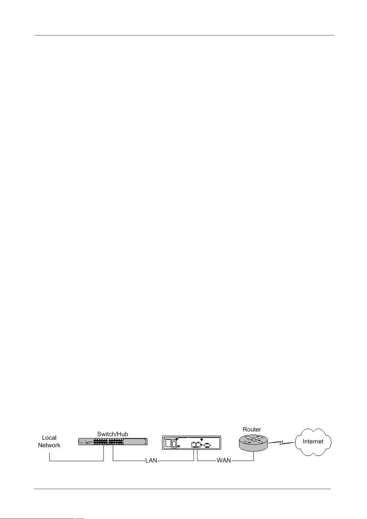
2.2 Deploy Bandwidth Manager On The Network
In order for Bandwidth Manager to manage traffic, the traffic must pass through Bandwidth Manager at a
useful point in a network. In most situations, the bandwidth manager should be placed behind the Internet
connection router.
This deployment allows the network administers to control all bandwidth based on business priorities and give
business-critical and time-sensitive applications guarantee bandwidth and higher priority. Business-critical
applications can receive maximum performance while other less urgent traffic is still available on remaining
bandwidth. Bandwidth Manager also provides comprehensive reporting functions to help monitor network and
bandwidth usage and allow adjustment of the bandwidth management policies accordingly.
- 5 -
Page 10

BM-2002 Bandwidth Manager User’s Manual
2.3 Install Bandwidth Manager To Your Network
¨ Choose an Installation Site
Select a suitable place on the network to install the Bandwidth Manager.
¨ Connect LAN Cables
Use standard LAN cables to connect your LAN side Switch or Hub to the LAN ports on Bandwidth
Manager. Both 10Base-T and 100Base-T connections can be used. The LAN and WAN port of
bandwidth manager support Auto-Negotiation to connect with best speed and duplex mode.
The LAN port of Bandwidth Manager is MDI port. Thus, you can just use straight network to connect
the LAN port to your switch or hub.
¨ Connect WAN Cable
Connect the router, DSL or Cable modem to the WAN port on Bandwidth Manager. The LAN and WAN
port of Bandwidth Manager are both MDI port. Thus, in some case, you may need to use cross-over
cable to connect your router, DSL or cable modem.
¨ Power Up
Connect the supplied power cord to Bandwidth Manager and use the power switch that in rear panel to
turn on the Bandwidth Manager. Use only the power cord provided. Using a different one may cause
hardware damage
¨ Check the LEDs
The PWR LED should be ON.
The HDD LED should flash for about 1 to 2 minutes, and then turn off. This LED will also flash when it is
reading data from the system memory.
Both the WAN and LAN’s LNK/ACT LED should be on or flash. If one of the LED is off, please check
the network connection. In some case, you may need to use cross-over cable to connect the LAN or
WAN port to your networks.
For more information, refer to Section 1.3 Bandwidth Manager Front View.
- 6 -
Page 11
BM-2002 Bandwidth Manager User’s Manual
Chapter 3:Getting Started
This chapter explains how to setup your computer to be a client to manage the Bandwidth Manager.
3.1 Configuration On A Client Side to link with Bandwidth Manager
You must use web browser to manage Bandwidth Manager with SSL protection. Before starting to configure
bandwidth management rules, you should configure client’s network setting first.
The default IP address of the Bandwidth Manager is as the following:
IP: 192.168.0.250
Mask: 255.255.255.0
Gateway: 192.168.0.254
To connect the bandwidth manager by web, you need to first change the management client’s network setup.
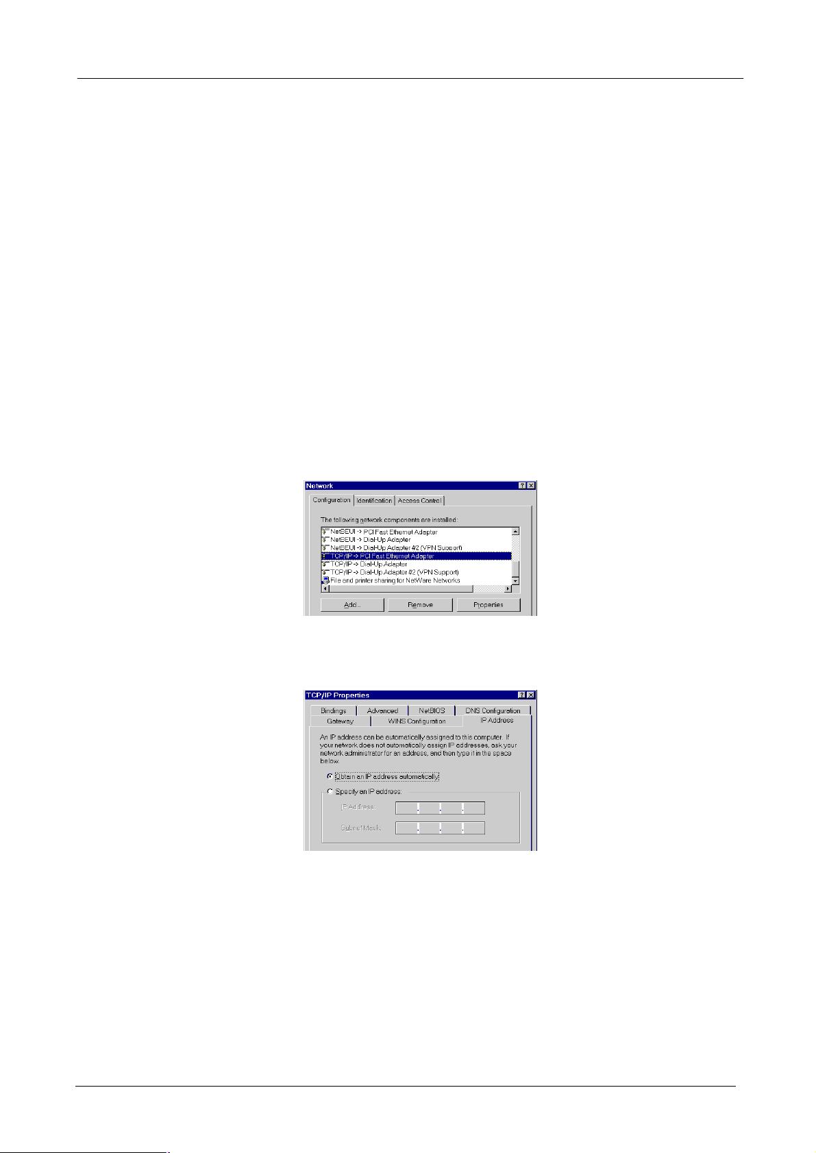
l Change TCP/IP Settings - Windows 9x/ME:
1. Select Control Panel - Network. You should see a screen like the following:
2. Select the TCP/IP protocol for your network card.
3. Click on the Properties button. You should then see a screen like the following.
4. Select “Specify an IP Address" and input “192.168.0.200” (or other IP in the same subnet) on the IP
Address field and “255.255.255.0” on Subnet Mask field.
5. Click OK and restart the PC to activate the IP configuration.
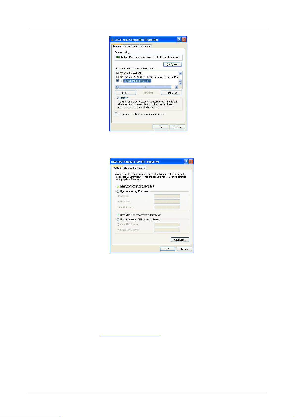
l Checking TCP/IP Settings - Windows 2000:
1. Select Control Panel - Network and Dial-up Connection.
- 7 -
Page 12
BM-2002 Bandwidth Manager User’s Manual
2. Right - click the Local Area Connection icon and select Properties. You should see a screen like the
following:
3. Select the TCP/IP protocol for your network card.
4. Click on the Properties button. You should then see a screen like the following.
5. Select “Use the following IP address" and input “192.168.0.200” (or other IP in the same subnet) on
the IP Address field and “255.255.255.0” on Subnet Mask field.
6. Click OK to activate the IP configuration.
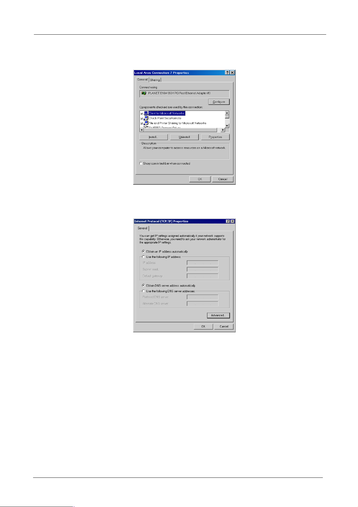
l Checking TCP/IP Settings - Windows XP
1. Select Control Panel - Network Connection.
2. Right click the Local Area Connection and choose Properties. You should see a screen like the
following:
- 8 -
Page 13
BM-2002 Bandwidth Manager User’s Manual
3. Select the TCP/IP protocol for your network card.
4. Click on the Properties button. You should then see a screen like the following.
5. Select “Use the following IP address" and input “192.168.0.200” (or other IP in the same subnet) on
the IP Address field and “255.255.255.0” on Subnet Mask field.
6. Click OK to activate the IP configuration.
3.2 Logging in as Administrator
Now you can communicate with Bandwidth Manager by web browser.
Open the web browser and type https://192.168.0.250:8889. Please note that “8889” is the port number of
Bandwidth Manager management interface, “https” here is to invoke the SSL of you web browser.
- 9 -
Page 14

BM-2002 Bandwidth Manager User’s Manual
You must key in user name and password to enter its web management interface.
The default user name is “admin” without password.
Then, you will enter Bandwidth Manager’s Configuration Menu.
- 10 -
Page 15

BM-2002 Bandwidth Manager User’s Manual
Chapter 4:Web Configuration
This chapter introduces how to configure the Bandwidth Manager to effectively control your bandwidth usage.
On the top of the Web interface, there is three major menu of the bandwidth manager:
System Settings: The basic system configurations
Policy Editor: The policy that will be used to manage the bandwidth
Report: The reporting system of the bandwidth manager base on the system settings and pre-defined
policy
The bandwidth manager will need the three parameters before it operates the bandwidth control: Host,
(illustrated in section 4.1.6), Services (illustrated in section 4.1.7) and Policy, (illustrated in section 4.2).
However, some of the configurations are also required. Please refer to the related section for the details.
4.1 System Settings
System settings menu contains three categories: “General” allows you to configure basic network
parameters, Internet connection bandwidth and date/time. “Catalog” allows you to define host and services
information which is needed for policy editor. “Admin” contains options to setup SNMP, backup / restore
settings, upgrade firmware, etc.
4.1.1 Information
This section shows information about the Bandwidth Manager
- 11 -
Page 16
BM-2002 Bandwidth Manager User’s Manual
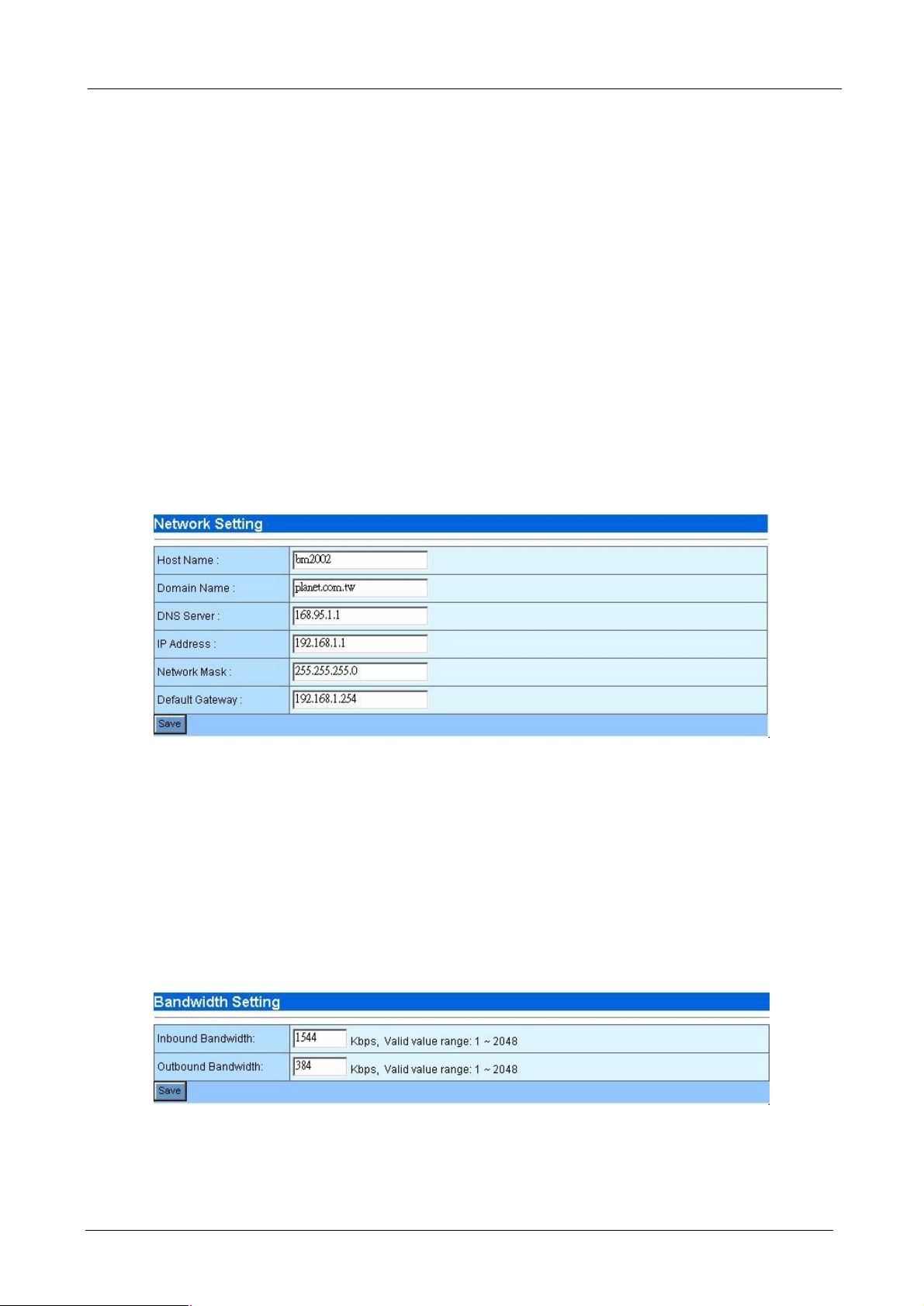
4.1.2 Network
You can setup Bandwidth Manager network settings in this section.
¨ Host Name: Please assign a name that is easy to remember for Bandwidth Manager.
¨ Domain Name: Your local network domain name.
¨ DNS Server: Your ISP’s DNS server IP or your DNS server IP.
¨ IP Address: Please assign an IP that is not in use by other device for Bandwidth Manager. The default
IP address of Bandwidth Manager is 192.168.0.250. This IP address can be on different subnet from
other internal hosts that you want to manage. For example, the Bandwidth Manager’s IP can be
192.168.0.250 and you can use it to manage internal hosts with IP in 10.x.x.x subnet.
¨ Network Mask: Your local network subnet mask. For example, 255.255.255.0.
¨ Default Gateway: Your local network default gateway. For example, 192.168.0.254.
¨ Save: Press save button to save all these configurations.
Note: If you have modified the IP address to a different IP subnet, you need to also modify the IP
address of management client’s IP address settings.
4.1.3 Bandwidth
Please enter your network bandwidth here. The sum of guaranteed bandwidth for all policies should not
exceed this value.
¨ Inbound Bandwidth: Input the downstream speed of your Internet connection (WAN port). The valid
value is form 1 to 2048 in units of kbps.
¨ Outbound Bandwidth: Input the upstream speed of your Internet connection (WAN port). The valid
value is form 1 to 2048 in units of kbps.
¨ Save: Press save button to save all these configurations.
BM-2002 allows up to 2Mbps (2048kbps) inbound/outbound bandwidth in both directions of its WAN port.
Please be aware of the bandwidth that your Internet services provider provided. It is not necessary to
configure Inbound and outbound bandwidth in the same values. Asymmetric bandwidth like 1.5Mbps
(1544Kbs) downstream, 384Kbps upstream ADSL is allowed.
- 12 -
Page 17
BM-2002 Bandwidth Manager User’s Manual
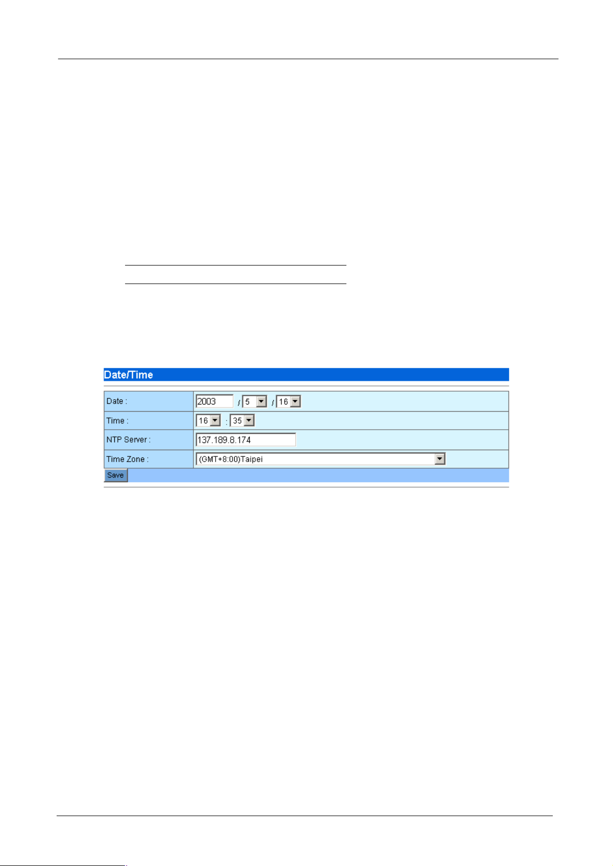
4.1.4 Date/Time
The Date/Time menu contains commands for setting Bandwidth Manager's time and date required for
correctly record the bandwidth usage time. User can directly input the date and time or specify the NTP server
for the device to synchronize with time-server. Click on “Date/Time” in the system settings menu bar and the
Date/Time screen will appear as illustrated below:
¨ Date: Input the year and select the Date from the pull-down list respectively.
¨ Time: Select the Time from the pull-down list respectively.
¨ NTP Server: Local NTP (Network time protocol) server IP or DNS name. If you want to manually
configure the date and time, left this field blank.
Note: Please find below NTP server web address for your reference to set the time-server.
http://www.eecis.udel.edu/~mills/ntp/clock1a.htm
http://www.eecis.udel.edu/~mills/ntp/clock2a.htm
¨ Time Zone: System administrator must select the time zone for the region.
¨ Save: Press save button to save all these configurations. If you have input a NTP server IP address or
DNS name, the Bandwidth Manager will try to inquire the current time and update the Date and Time
field.
The Date/Time information will be used in the reporting system (refer to section 4.3). If your BM-2002 can
reach to the Internet, you can find the nearest NTP server in the Internet for your BM-2002 that should provide
the accurate date and time for the bandwidth manager.
4.1.5 Host
BM-2002 can control the bandwidth usage via host IP address. You must define local and/or remote user’s
IP address that you want to manage to the host catalog. This host catalog is useful on defining policy. The
total number of host catalog, service catalog and policies cannot exceed 256.
The Host Catalog page lists all the defined hosts with host name, IP address and location. On the top of the
host table, the following buttons are available:
¨ New - Create new host catalog.
¨ Prev - Go to previous page.
¨ 1, 2, … - First, second, … page.
¨ Next - Next page.
On the Action field of each host name, the following two buttons are provided:
- 13 -
Page 18

BM-2002 Bandwidth Manager User’s Manual
- Modify the host catalog
- Delete the host catalog
After clicking “New” or Modify button, the following host configuration page will be shown:
¨ Host Name: The name of specified IP address or a range of IP address. With it, you can easily tell the
bandwidth usage through this meaningful name. For example, a name like “Web_server” to a dedicated
IP, or “Acct_Group” for the IP range of accounting department.
¨ IP Address: IP or IP range of this host. You can input by single IP address, IP range, IP subnet or mix
of about formats and divided by comma. For example, 192.168.0.1, 192.168.0.5, for the two devices
using (IP address 1 and 5); 192.168.0.20-30 (for the range of IP address from 20 to 30), and
192.168.0.128/28 (for IP address from 128 to 143).
¨ Location: If the host’s position is on the WAN side of Bandwidth Manager in the network, please choose
external. If the host’s position is on the LAN side of Bandwidth Manager, please choose internal.
¨ Description: Additional description of this host(s).
¨ Save/Cancel: Press save button to save above configurations and Cancel button to discard your
configurations.
After clicking Save or Cancel button, the Host Catalog page will be shown again. To edit the host(s) you
have configured, please click Modify button on the Action field. To remove the host(s) you have configured,
please click Delete button on the Action field.
- 14 -
Page 19
BM-2002 Bandwidth Manager User’s Manual
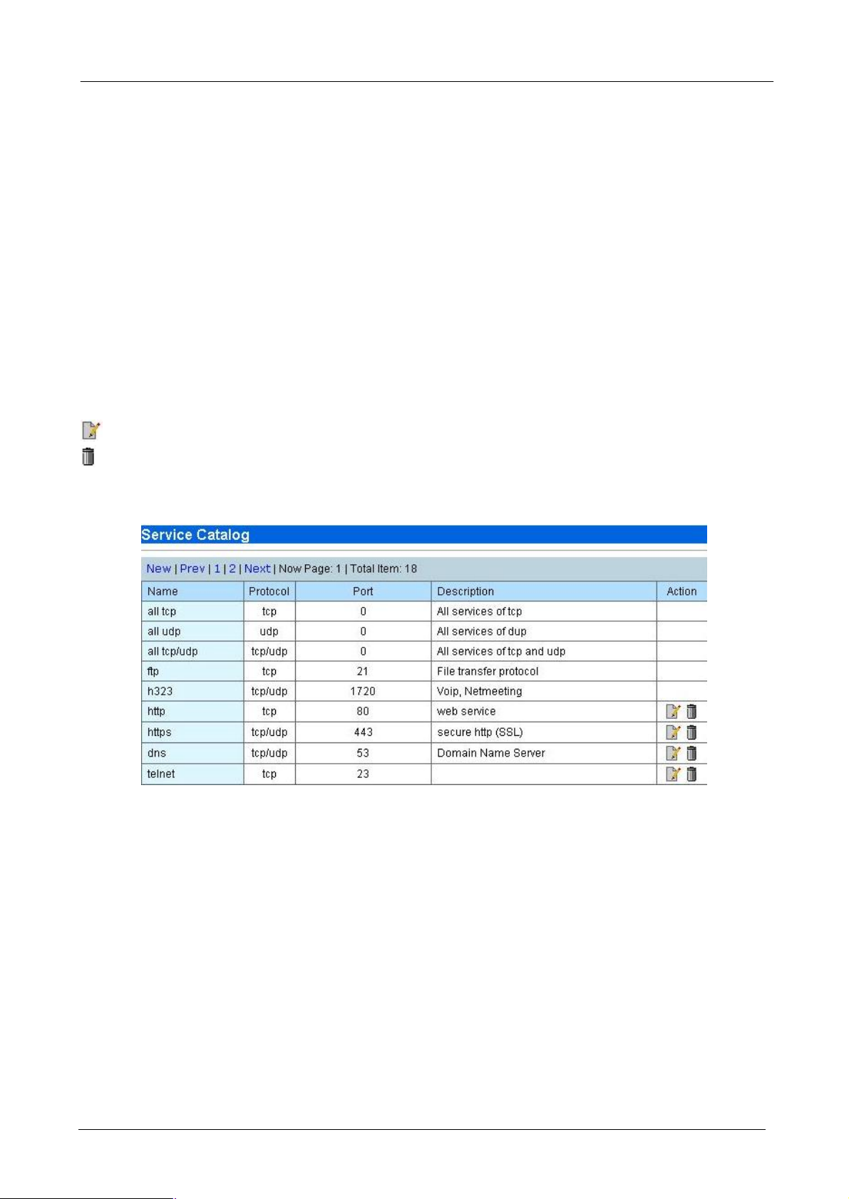
4.1.6 Service
The Service Catalog contains all the popular services that you may want to manage. The total number of host
catalog, service catalog and policies can not exceed 256. The bandwidth Manager have contained 22
predefine services. For other Internet services, however, you can direct click on New to add the services or
click on Modify icon to modify and remove by click on the delete icon.
¨ New - Create new service.
¨ Prev - Go to previous page.
¨ 1, 2, … - First, second, … page.
¨ Next - Next page.
On the Action field of each service name, the following two buttons are provided:
- Modify the Service catalog
- Delete the Service catalog
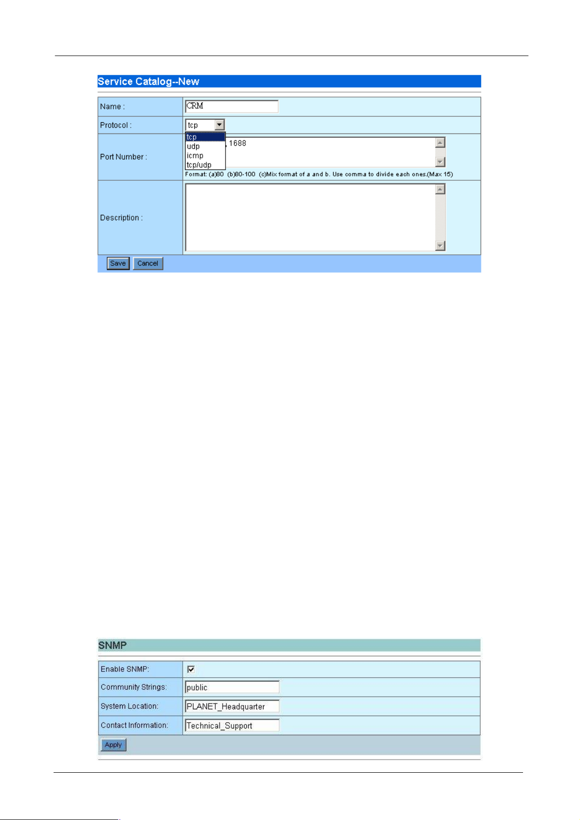
After clicking “New” or Modify button, the following service configuration page will be shown.
- 15 -
Page 20
BM-2002 Bandwidth Manager User’s Manual
¨ Name: Name of this service. For example, www, http or telnet.
¨ Protocol: Choose which kind of protocol this service use. For example, Telnet is using TCP; voice data
transmission like PLANET VoIP gateway, is using UDP.
¨ Port Number: enter the port number this service use. For example, Telnet will use port 23, http will use
port 80, PLANET VoIP gateway is using 30000 to 30100 by default.
¨ Description: Additional description of this service.
¨ Save/Cancel: Press save button to save above configurations and Cancel button to discard your
configurations.
After clicking Save or Cancel button, the Service Catalog page will be shown again. To edit the service you
have configured, please click Modify button on the Action field. To remove the service you have configured,
please click Delete button on the Action field.
4.1.7 SNMP
Use the SNMP Configuration screen to display and modify parameters for the Simple Network Management
Protocol (SNMP). The device includes an on-board SNMP agent which monitors the status of its hardware, as
well as the traffic passing through it. A computer attached to the network, called a Network Management
Station (NMS), can be used to access this information. Access rights to the agent are controlled by community
string. To communicate with the device, the NMS must first submit a valid community string for authentication.
- 16 -
Page 21
BM-2002 Bandwidth Manager User’s Manual
¨ Enable SNMP: Check this box to enable the SNMP function.
¨ Community Strings: A community entry authorized for management access. The network
management station must use same string to read the SNMP data from the device.
¨ System Location: Specifies the area or location where the device resides.
¨ Contact Information: Contact person for the device.
¨ Save: Press save button to save all these configurations.
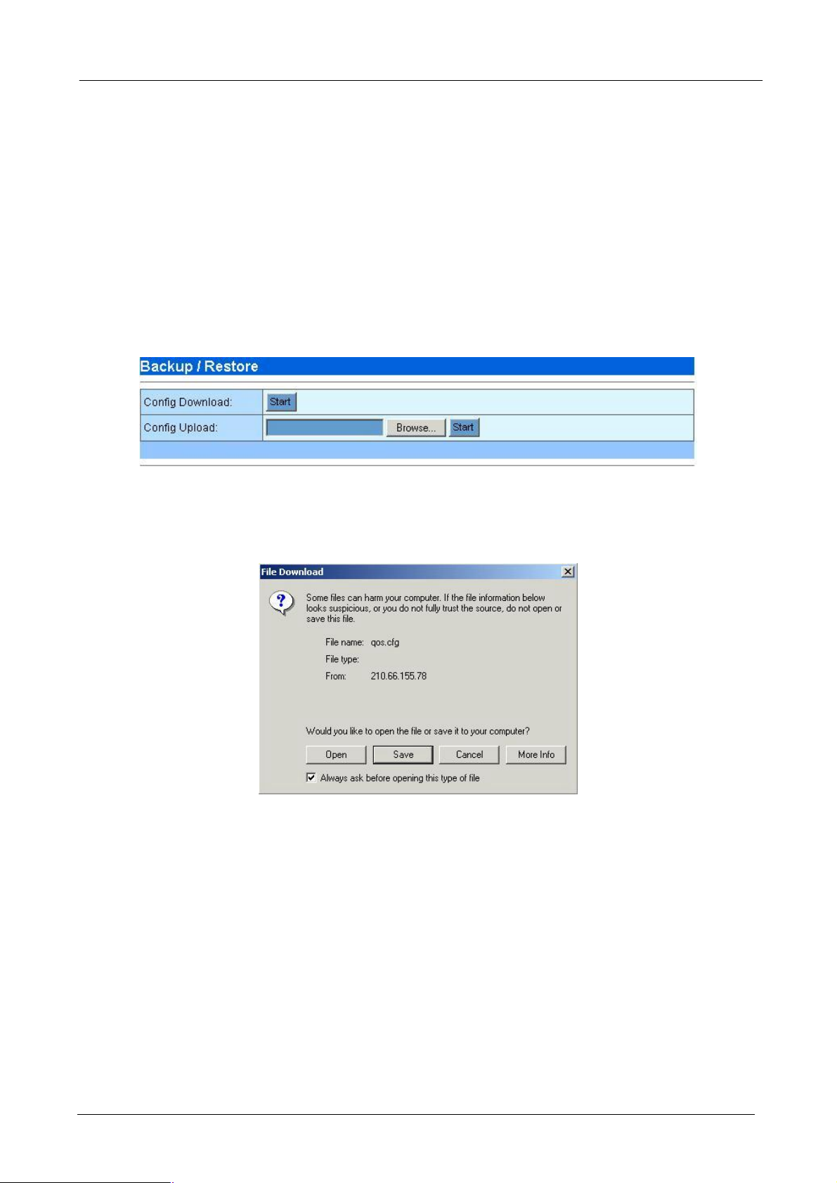
4.1.8 Backup/Restore
You can easily backup and restore the current configuration of Bandwidth Manager.
¨ Backup: Press “Start” button on the Config Download row to download the configuration file of
Bandwidth Manager to your local client side. The following page will then be shown. Click “Save” to
save the configuration file.
Note: It is strongly recommended to backup your file configuration file whenever you have
complete the configurations.
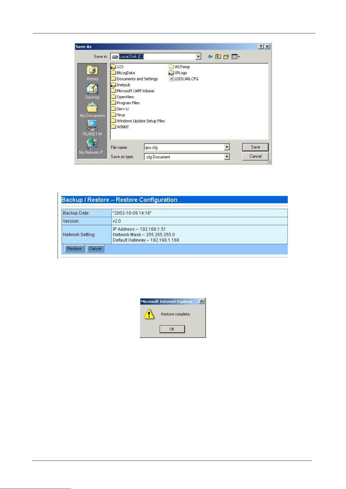
¨ Restore: Press “Browse…” button to select the configuration file you have saved before.
- 17 -
Page 22
BM-2002 Bandwidth Manager User’s Manual
Then press “Start” button to start upload configuration file to Bandwidth Manager.
After confirm backup date and network settings, press “Restore” button to start restore all of the configurations
to Bandwidth Manager.
After restore is completed, a “Restore complete“ window prompts. Click “OK” to continue.
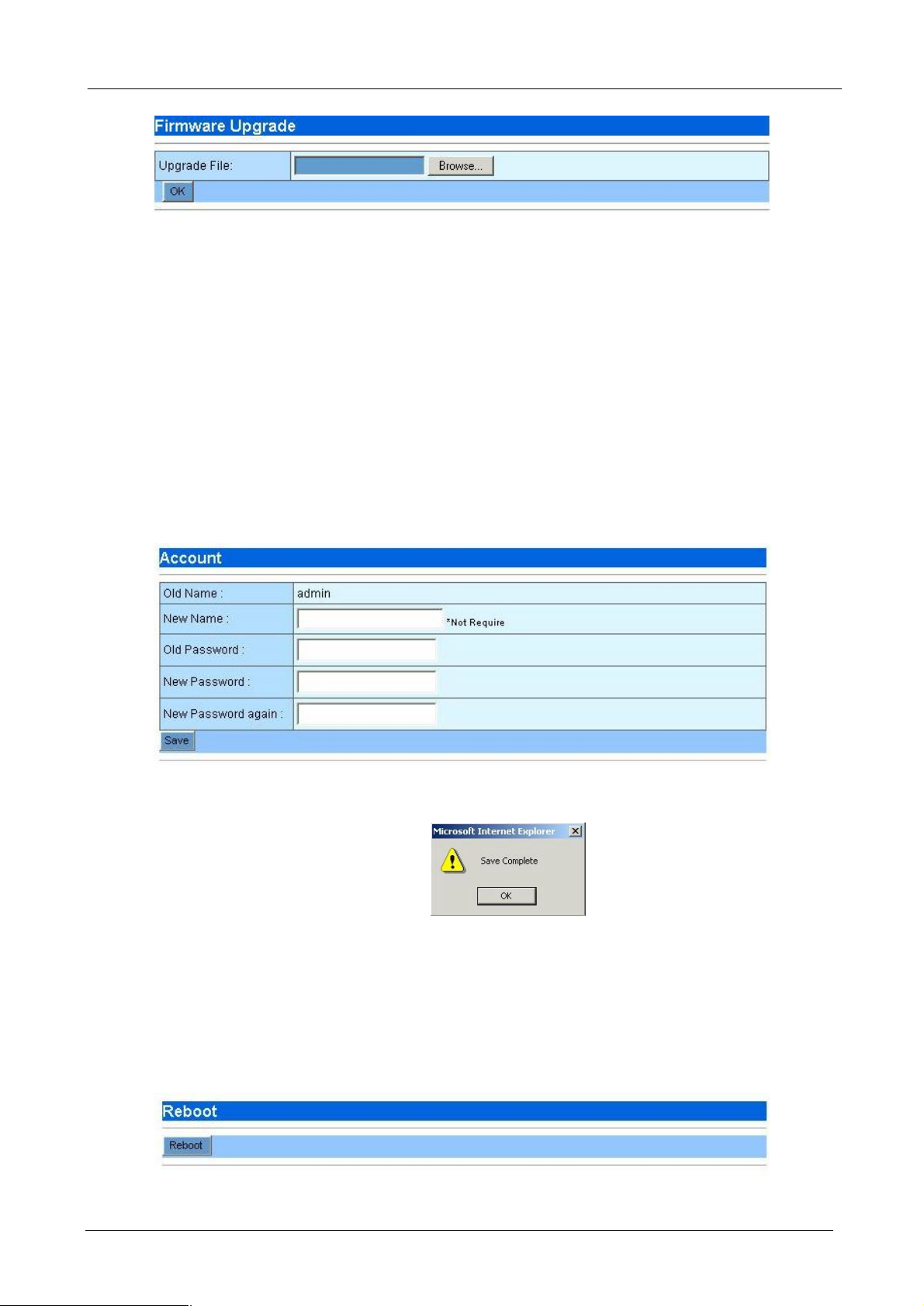
4.1.9 Firmware Upgrade
PLANET will announce new patch or firmware on the website for users. You can download the latest firmware
from the website and use this screen to upgrade.
- 18 -
Page 23
BM-2002 Bandwidth Manager User’s Manual
4.1.10 Account
You can change the user name and password when you log in on this window.
¨ Old Name: The old name you use to log in Bandwidth Manager
¨ New Name: The new name that you want to change.
¨ Old Password: Enter old password that you use before.
¨ New Password: The new password that you want to change.
¨ New Password Again: Confirm new password again.
¨ Save: Press “Save” button to save all the configurations.
After save is completed, the following window is prompted, click “OK” to continue.
Note: For safety reason, it is strongly recommended to change the default password and store the password
in a safe place.
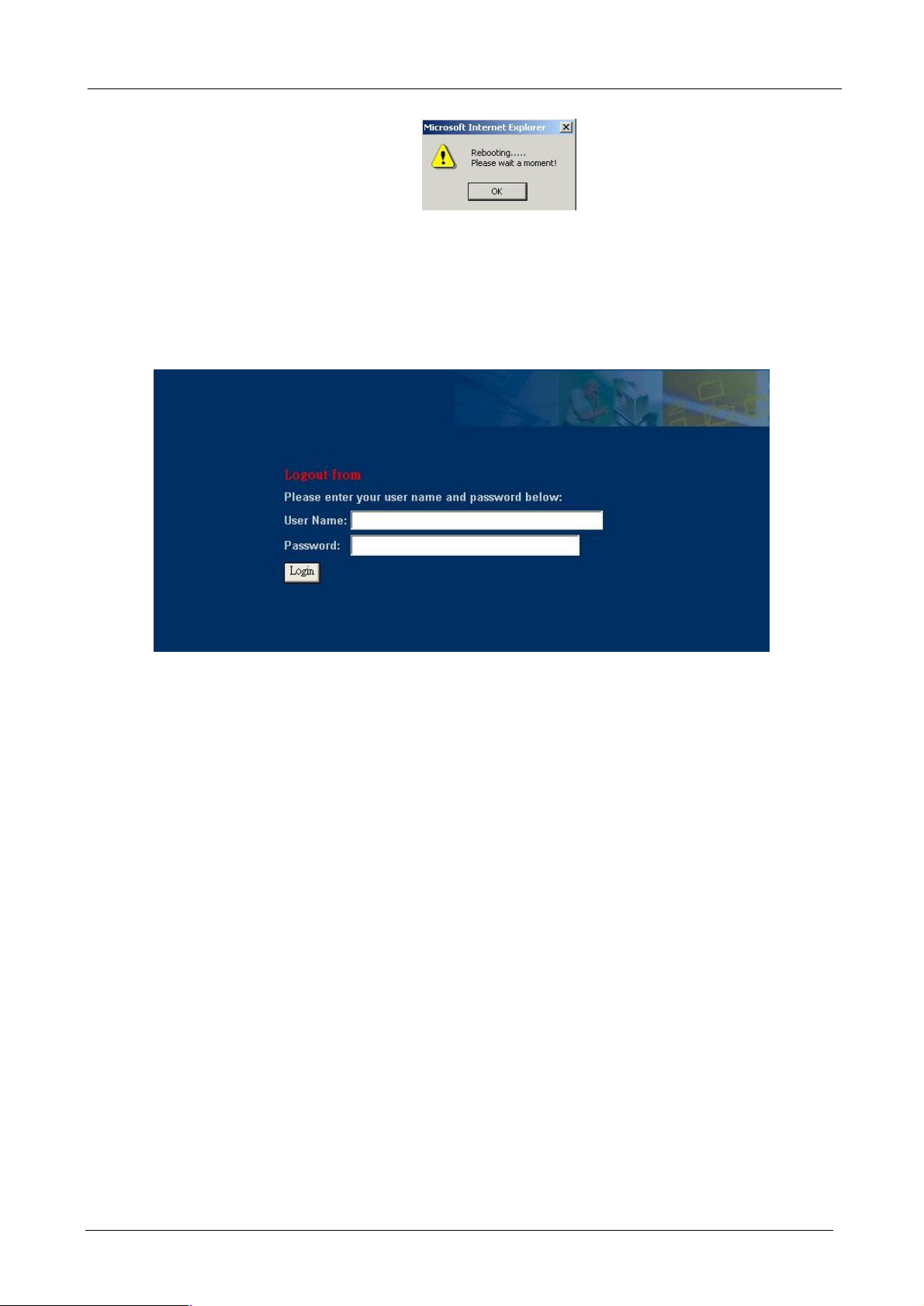
4.1.11 Reboot
You can reboot Bandwidth Manager from web and by Reset button on the rear side of this device.
Press “Reboot” button to reboot the Bandwidth Manager, while reboot is processing, this info prompt.
- 19 -
Page 24
BM-2002 Bandwidth Manager User’s Manual
4.1.12 Logout
You can logout the management interface after finishing your configuration.
- 20 -
Page 25
BM-2002 Bandwidth Manager User’s Manual
4.2 Policy Editor
You can setup all the control policies, make IP/MAC binding for security and control access right in this
section.
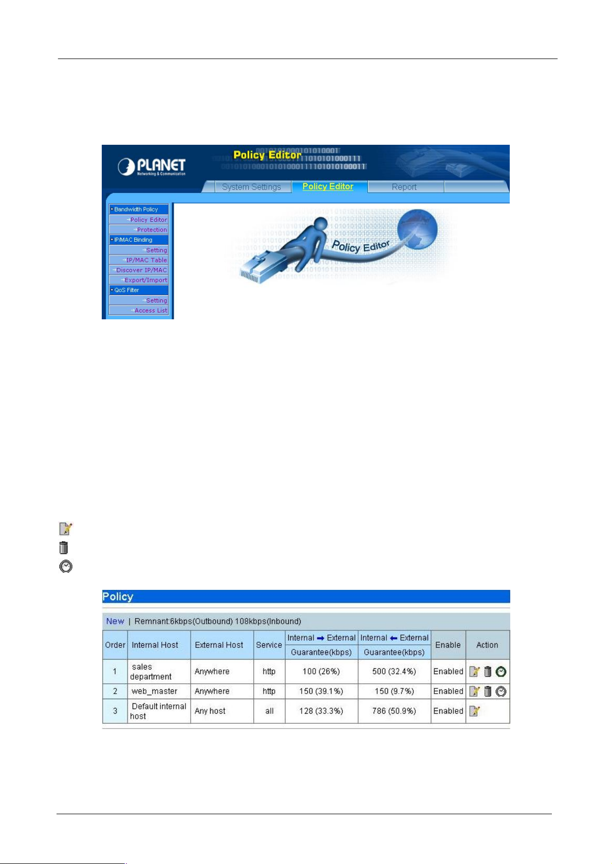
4.2.1 Policy Editor
Here will list all the policies that you have made. The total number of host catalog, service catalog and policies
can not exceed 256. The following functions are provided on this page:
¨ New - Create new policy
¨ Prev - Go to previous page.
¨ 1, 2, … - First, second, … page.
¨ Next - Next page.
- Modify the existing policy
- Delete the policy
- Schedule the time when the policy will be enabled.
Press “New” or Modify button, the policy configuration page will be shown as the following.
¨ Order: Policies processing sequence. When the Bandwidth Manager receives a packet, it will find the
packet’s Internal Host, External Host and Service and check which policy the packet applies. Order 1
policy will be the first policy to check and so on. When the Bandwidth Manager find a policy fit to the
- 21 -
Page 26

BM-2002 Bandwidth Manager User’s Manual
packet, it will stop the checking and apply the guarantee bandwidth, burst bandwidth and priority to the
packet. Thus, always put mission-critical traffic policy in the front to get higher performance.
¨ Internal Host: The internal host that you want to manage. You have to first define the internal host on
host catalog.
¨ External Host: The destination host that you want to manage. You have to first define the external host
on host catalog. You can build an external host if the Bandwidth Manager is deployed in a LAN to LAN
(VPN, Wireless, G.SHDSL, etc) network environment.
¨ Service: The service that you want to manage. The services must be defined on the service catalog.
¨ Guarantee: Assign guaranteed bandwidth in kbps to this policy. This is the minimum bandwidth that the
policy guarantees. The sum of all guarantee bandwidth should not exceed the inbound and outbound
bandwidth settings on chapter 4.1.3.
¨ Burst: This policy’s maximum bandwidth may be used. This is the maximum bandwidth that the policy
can use.
¨ Priority: The packet’s priority on this policy. When packets compete un-guaranteed bandwidth, packets
on higher priority policy always process first.
¨ Enable: Enable or disable this policy.
¨ Save/Cancel: Press “Save” button to save above configurations and “Cancel” button to discard your
configurations.
You may use button on policy list to schedule when each policy will be enabled.
¨ Start time: Time to start policy activation.
¨ End time: Time to terminate policy activation.
¨ Week: Days in a week that you want QoS policy to take effect.
- 22 -
Page 27

BM-2002 Bandwidth Manager User’s Manual
¨ Enable: Enable or disable this schedule.
¨ Save/Cancel: Press “Save” button to save all the configurations and “Cancel” button to discard your
configurations.
4.2.2 Protection
The Bandwidth Manager provides extended capabilities for filtering out any malicious attacks based on TCP,
UDP, or ICMP protocols. This greatly improves the security of your bandwidth, and guarantees that such
attacks will not disrupt the normal operation of your systems. While filtering out detected malicious traffic, your
network will be able to operate normally.
¨ Deny SYN Flood: TCP SYN Flood is one kind of attack that an attacker makes connection requests
aimed at the victim device with packets with unreachable source addresses. The device is not able to
complete the connection requests and, as a result, the device wastes all of its network resources,
resulting in shutting down a device. By defining a SYN attack threshold, the bandwidth manager allows
only the certain number of packets with unreachable source addresses each second.
¨ UDP Flood Attack: UDP is a connectionless protocol and it does not require any connection setup
procedure to transfer data. An UDP Flood Attack is possible when an attacker sends a UDP packet to a
random port on the victim device. When the victim device receives an UDP packet, it will determine what
application is waiting on the destination port. When it realizes that there is no application that is waiting
on the port, it will generate an ICMP packet of destination unreachable to the forged source address. If
enough UDP packets are delivered to ports on victim, the device will go down. By defining a UDP flood
threshold, the bandwidth manager allows only the certain number of destination unreachable UDP
packets each second.
¨ ICMP Flood Attack: An ICMP flood is usually accomplished by broadcasting either a bunch of pings or
UDP packets. The idea is, to send so much data to your system, that it slows you down so much that
you're disconnected from IRC due to a ping timeout. By defining a ICMP flood attack threshold, the
bandwidth manager allows only the certain number of ICMP packets each second.
¨ Deny Port Scan: Most attackers will first scan all port of the victim to know which services are running
and then determined how to attack. Deny port scan will make hacker much hard to attack your internal
LAN.
¨ Circumventing Path MTU Discovery with MSS Clamping(for ADSL, cable, PPPoE): An Ethernet
packet provides maximum 1460 bytes payload. However, not all parts of the Internet support full 1460
bytes of payload per packet. It is therefore necessary to try and find the largest packet that will 'fit', in
order to optimize a connection. This process is called 'Path MTU Discovery', where MTU stands for
'Maximum Transfer Unit.' However, Path MTU Discovery is not always working. MSS (Maximum
- 23 -
Page 28

BM-2002 Bandwidth Manager User’s Manual
Segment Size) is another way to set the maximum packet size. This is a field in the TCP Options part of a
SYN packet. By enable MSS clamping, the bandwidth manager calculates the proper MSS for your link
and tell the remote side unequivocally 'do not ever try to send me packets bigger than this value'.
Enable this function if your Internet connection is ADSL or cable modem and you meet connection
problem with your ISP.
4.2.3 IP/MAC Binding Setting
IP/MAC Binding allow you to bind IP and MAC to allow or block only certain IP/MAC or MAC for passing
through the bandwidth manager. The IP/MAC binding table can be build by importing from text file or
discovering by the bandwidth manager. The following functions are provided on this page:
¨ Binding Function: Enable or disable binding function.
¨ Binding Mode: There are two options on binding mode –
Block the traffic when not defined or not match in the IP/MAC table. Select this option if
you only want to allow the Internet access of defined and enabled IP/MAC addresses.
Allow the traffic when not defined or match in the IP/MAC table. Select this option if you
only want to block the Internet access of defined and enabled IP/MAC addresses.
4.2.4 IP/MAC Table
Here will list all the defined IP/MAC binding table that you have built. The following functions and information
are provided on this page:
¨ New - Create new IP/MAC binding.
¨ Delete All - Delete all the IP/MACbinding table
¨ Prev - Go to previous page.
¨ 1, 2, … - First, second, … page.
¨ Next - Next page.
On the Action field of each IP address, the following two buttons are provided:
- Modify the IP/MAC binding
- 24 -
Page 29

BM-2002 Bandwidth Manager User’s Manual
- Delete the IP/MAC binding
Press “New” or modify button, the IP/MAC Table configuration page will be shown as the following.
¨ MAC Address: The MAC address of the host in format of xx:xx:xx:xx:xx:xx.
¨ IP Address: The IP address of the host in format of xxx.xxx.xxx.xxx. If you want to specify the MAC
address only, input 0.0.0.0 here.
¨ Enable: Enable or Disable the IP/MAC binding. Only enabled IP/MAC binding is applied to the allow or
block blocking mode.
4.2.5 Discover IP/MAC
The Discover IP/MAC function help you to find all the IP/MAC binding on your local network. The following
functions and information are provided on this page:
¨ IP Subnet: Input a class C subnet for the Bandwidth Manager to find all host and their MAC address on
the subnet.
¨ Ignore Defined: Select Yes if you want to ignore the defined IP/MAC binding. However, if only MAC
address or IP address is defined on the IP/MAC table, the bandwidth manager will still show the IP/MAC
binding on the result window.
¨ Start Discover: Click this button to start the discovery process.
After clicking the “Start Discover”, a warning message is shown to prompt for waiting a moment and don’t
press stop button of browser. A screen similar to the following is then shown for all IP/MAC address the
bandwidth manager found on the IP subnet you specify. The following functions and information are
provided on this page:
- 25 -
Page 30

BM-2002 Bandwidth Manager User’s Manual
¨ Clear All: Unselect al the IP/MAC binding.
¨ Select All: Select all the IP/MAC binding.
¨ Import: Import the selected IP/MAC binding to the IP/MAC Table.
¨ Cancel: Discard the discover result and go back to Discover IP/MAC page.
On the table, each item has 3 fields:
¨ Select: Check this box to import to the IP/MAC table after clicking Import button.
¨ IP Address: IP address the bandwidth manager discovers. If there is already an IP address defined on
the IP/MAC table, a * will be shown after the address to denote it is defined on the IP/MAC table.
¨ MAC Address: IP address the bandwidth manager discovers. If there is already a MAC address defined
on the IP/MAC table, a * will be shown after the address to denote it is defined on the IP/MAC table.
4.2.6 Export / Import
This page allows you to export the IP/MAC table or import IP/MAC binding from a text file.
¨ Export IP/MAC file: export the IP/MAC data to a file named ipmac.dump in text format.
¨ Import IP/MAC file: Click “Browse…” to select the IP/MAC table file you want to import and then click
“Start” to import.
Each item in the IP/MAC Table file has 3 fields and use “space” to divide each field:
Field 1: IP address
Field 2: MAC address
Field 3: Enabled or disabled, 1 for enabled, 0 for disabled.
An example is as the following:
192.168.0.1 00:30:4F:18:CB:D4 1
192.168.0.2 00:30:4F:23:45:64 1
192.168.0.3 00:30:4F:AB:CD:EF 0
- 26 -
Page 31

BM-2002 Bandwidth Manager User’s Manual
4.2.7 Access Control Setting
Access Control function allows you to control the access right of packets based on their IP address and
TCP/UDP port. In Access Control setting, you can enable or disable the access control function and choose
its access control mode.
¨ Access Control Function: Enable or disable access control function. If it is enabled, the access
control checking will be processed first before bandwidth policy checking.
¨ Access Control Mode: There are two options on access control mode –
Allow the traffic when deny rules aren’t defined in the Access List. You can choose allow
or deny on the policy field on the Access List. Select this option if you only want to block the
Internet access of defined IP addresses and TCP/UDP port with deny policy.
Deny the traffic when allow rule aren’t defined in the Access List. Select this option if you
only want to allow the Internet access of defined IP addresses and TCP/UDP port with allow
policy.
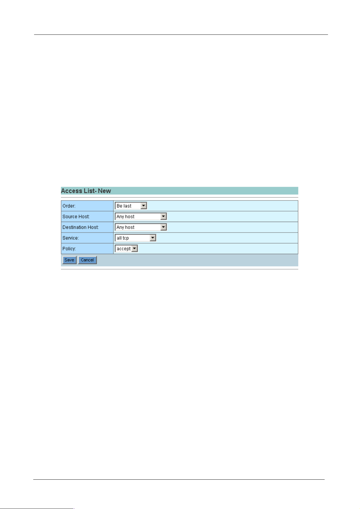
4.2.8 Access List
Access List allow you to define the access right based on traffic’s source and destination IP address, and
TCP/UDP port (service). The following functions and information are provided on this page:
¨ New - Create new service.
¨ Prev - Go to previous page.
¨ 1, 2, … - First, second, … page.
¨ Next - Next page.
¨ Action - On the Action field of each service name, the following two buttons are provided:
- Modify the Access list
- Delete the Access list
- 27 -
Page 32
BM-2002 Bandwidth Manager User’s Manual
Press “New” or Modify button, the access list configuration page will be shown as the following.
¨ Order: Access List processing sequence. When the Bandwidth Manager receives a packet, it will find the
packet’s Source Host, Destination Host and Service and check which Access List the packet applies.
Order 1 will be the first list to check and so on. When the Bandwidth Manager find a list fit to the packet, it
will stop the checking and accept or deny the packet. Thus, always put mission-critical traffic list in the
front to get higher performance.
¨ Source Host: The source host that you want to control. You have to first define the source host on host
catalog. This is the host(s) which originates the network service request. It can be on LAN(internal) or
WAN(external) side.
¨ Destination Host: The destination host that you want to control. You have to first define the destination
host on host catalog. This is the host(s) which receives the network service request. It can be on
LAN(internal) or WAN(external) side.
¨ Service: The service that you want to control. The services must be defined on the service catalog.
¨ Policy: Accept or deny this access list.
¨ Save/Cancel: Press “Save” button to save above configurations and “Cancel” button to discard your
configurations.
- 28 -
Page 33
BM-2002 Bandwidth Manager User’s Manual
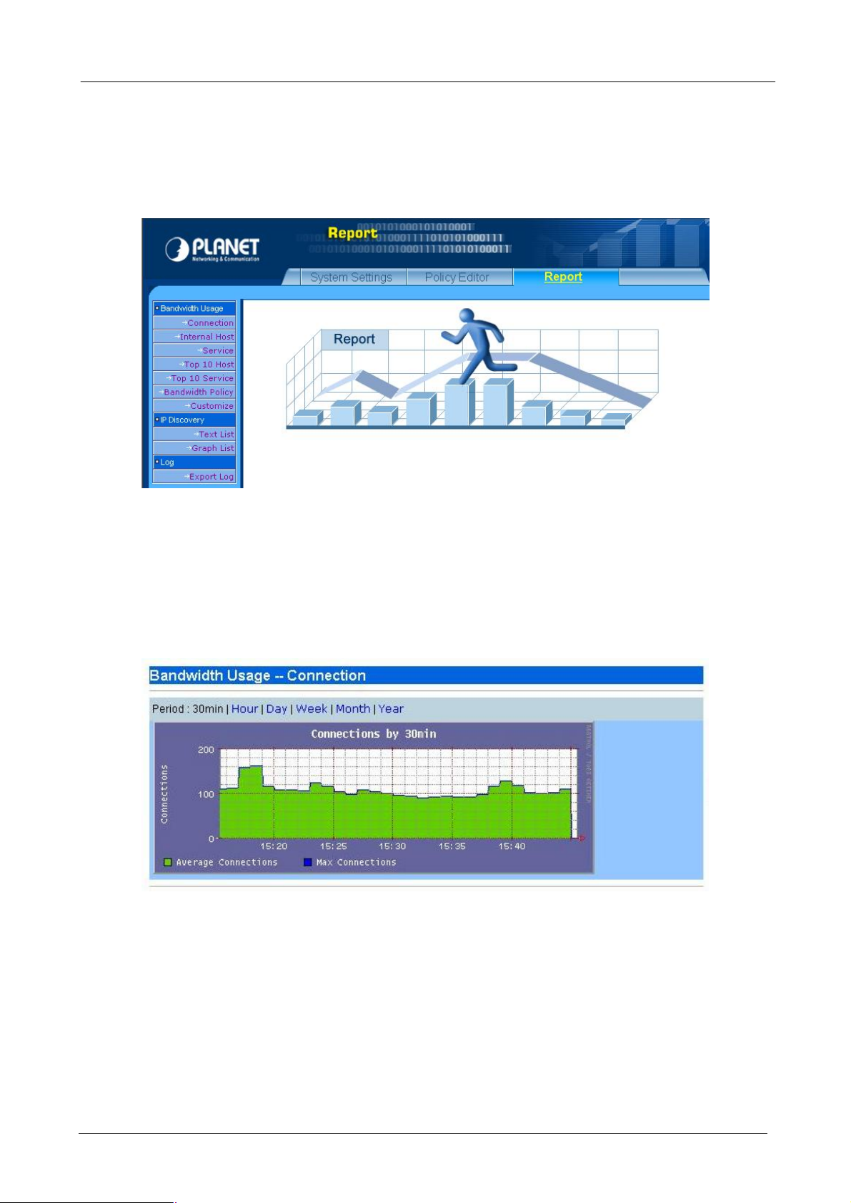
4.3 Report
PLANET Bandwidth Manager can monitor all the inbound and outbound packets and automatically categorize
to provide versatile reports. These reports help you to analyze the traffic flowing through your Bandwidth
Manager and aid you in determining the optimum configuration for your system.
4.3.1 Connection
This report shows all the connections passed Bandwidth Manager and you can choose several periods that
you want it to display.
4.3.2 Internal Host
This report shows the bandwidth usage rate of each internal host. And you can choose several kinds of period
that you want it to display. The graph report shows both inbound and outbound traffic.
- 29 -
Page 34
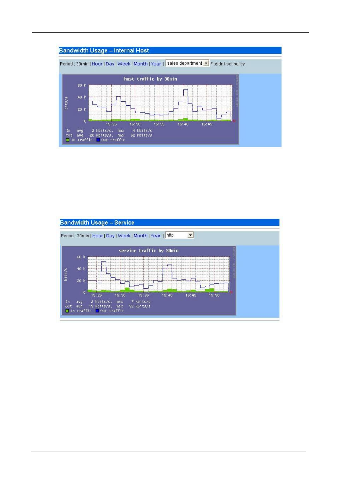
4.3.3 Service
BM-2002 Bandwidth Manager User’s Manual
This report shows the bandwidth usage rate that each service used. And you can choose several kinds of
period that you want it to display. The graph report shows both inbound and outbound traffic.
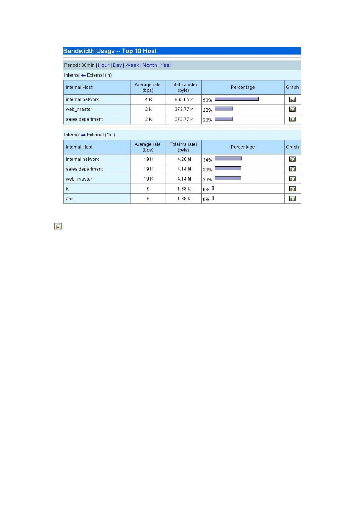
4.3.4 Top 10 Host
This report shows top 10 bandwidth usage of internal hosts. And you can choose several kinds of period that
you want it to display.
- 30 -
Page 35
BM-2002 Bandwidth Manager User’s Manual
Press button to view graph report of specified internal host. The graph report shows both inbound and
outbound traffic.
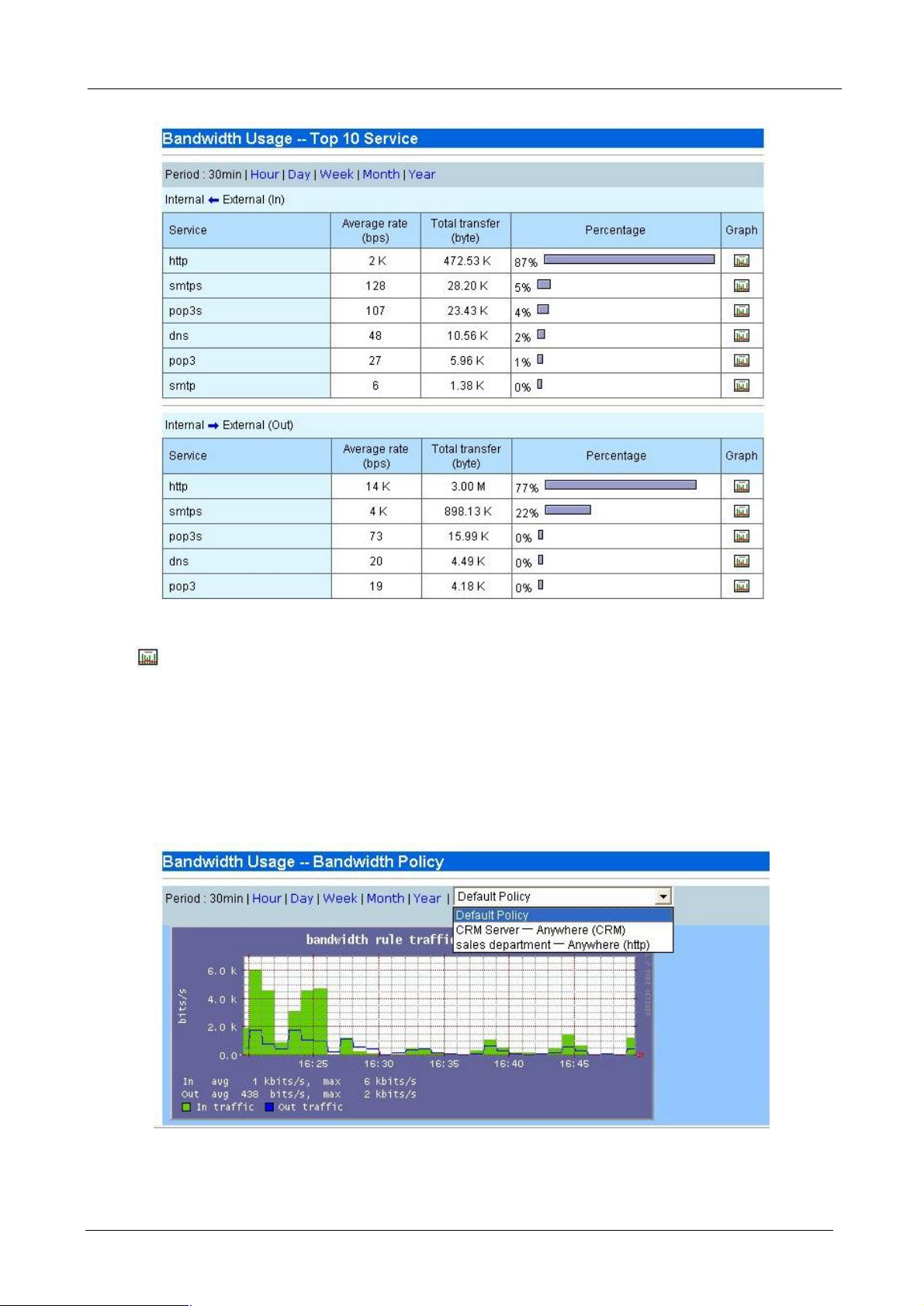
4.3.5 Top 10 Service
This report shows top 10 bandwidth usage of services. And you can choose several kinds of period that you
want it to display.
- 31 -
Page 36
BM-2002 Bandwidth Manager User’s Manual
Press button to view graph report of specified service. The graph report shows both inbound and
outbound traffic.
4.3.6 Bandwidth Policy
You can choose each policy that you want to view. And you can choose several kinds of period that you want
it to display. The graph report shows both inbound and outbound traffic.
- 32 -
Page 37
BM-2002 Bandwidth Manager User’s Manual
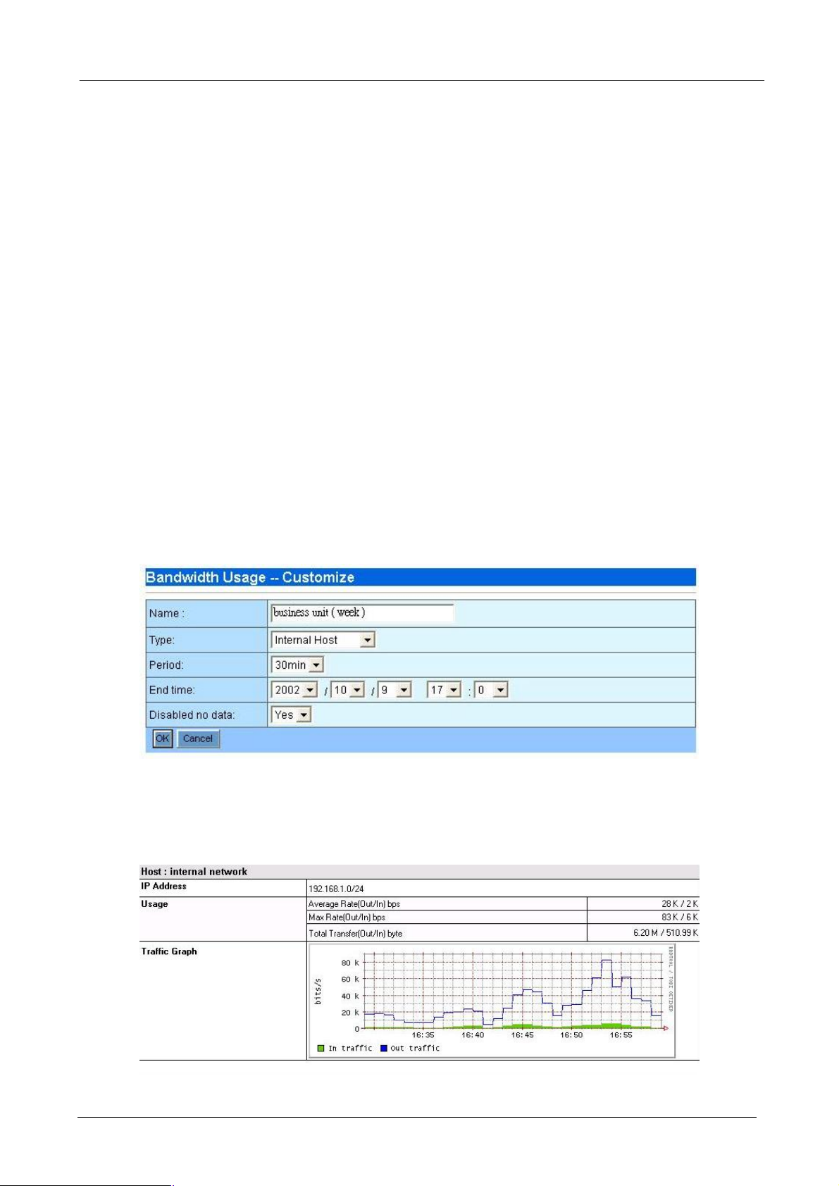
4.3.7 Customize
This function offers system administrator to easily collect network bandwidth usage rate information to report.
The Bandwidth Manager will record the traffic of all the defined host catalog, service catalog and policy and
save the following data in a specified time period:
¨ The average bandwidth usage per minute for past 12 hours
¨ The average bandwidth usage per 10 minutes for past 60 hours
¨ The average bandwidth usage per hour for past 10 days
¨ The average bandwidth usage per day for past 360 days (1 year)
Thus, when you use customize to show the bandwidth usage statistic, please make sure you do not use a
time period that Bandwidth Manager does not record.
¨ Name: Customized report title.
¨ Type: Type of report. Three options provided: Internal host / service / bandwidth policy.
¨ Period: Choose several periods that you wants to do a routine record in our report
¨ End Time: Stop to record network bandwidth usage rate in this report.
¨ Disabled no data: If there is no data in some item. You may decide that enable or disable these items
display on the report.
Press “OK” button to generate a report you have customized
The following is a part of customized report as a sample.
- 33 -
Page 38
BM-2002 Bandwidth Manager User’s Manual
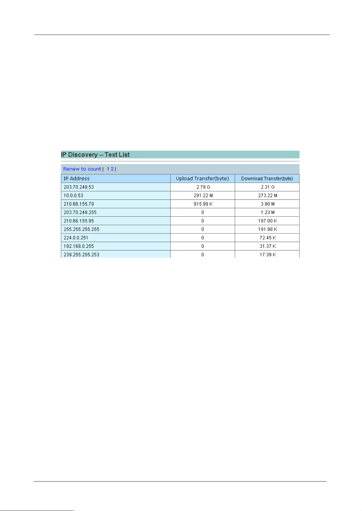
4.3.8 IP Discovery - Text List
This function lists all the internal IP addresses which have pass through Bandwidth Manager and their upload
and download data for past one day. This offer you an easily way for you to know which host use most
bandwidth and how many bandwidth it have used for past one day. It also helps you to find the hidden
node(s) on your network and take adequate action.
Press “Renew to count” button that reset the data to zero and start to count all the internal IP bandwidth usage
again. You can also press “Upload Transfer (byte)” button to sort by upload transfer rate and press
“Download Transfer (byte)” button to sort by download transfer rate.
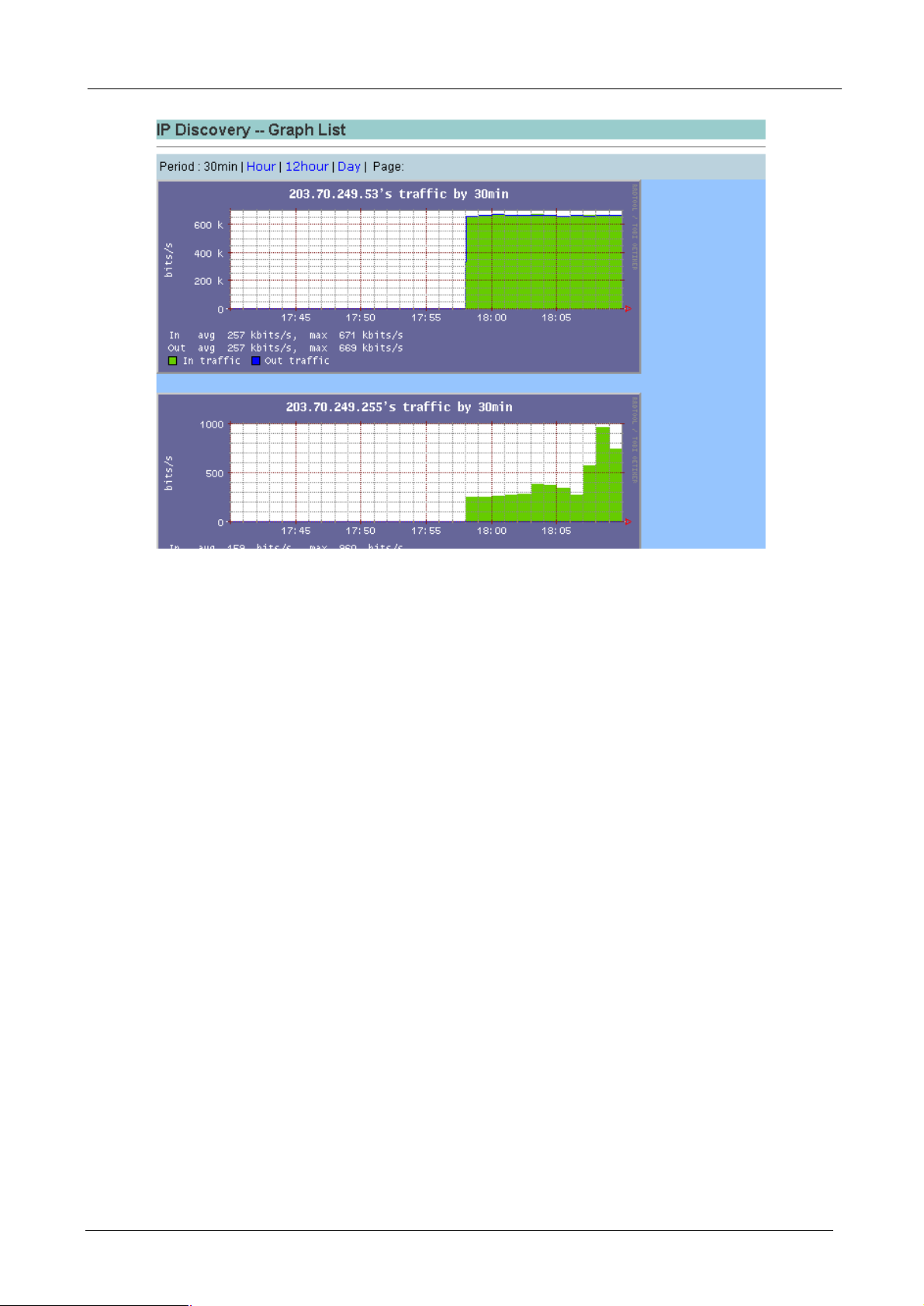
4.3.9 IP Discovery - Graph List
This function provide a graph view all the internal IP addresses which have pass through Bandwidth Manager
and their upload and download data and you can choose several periods that you want it to display.
- 34 -
Page 39
BM-2002 Bandwidth Manager User’s Manual
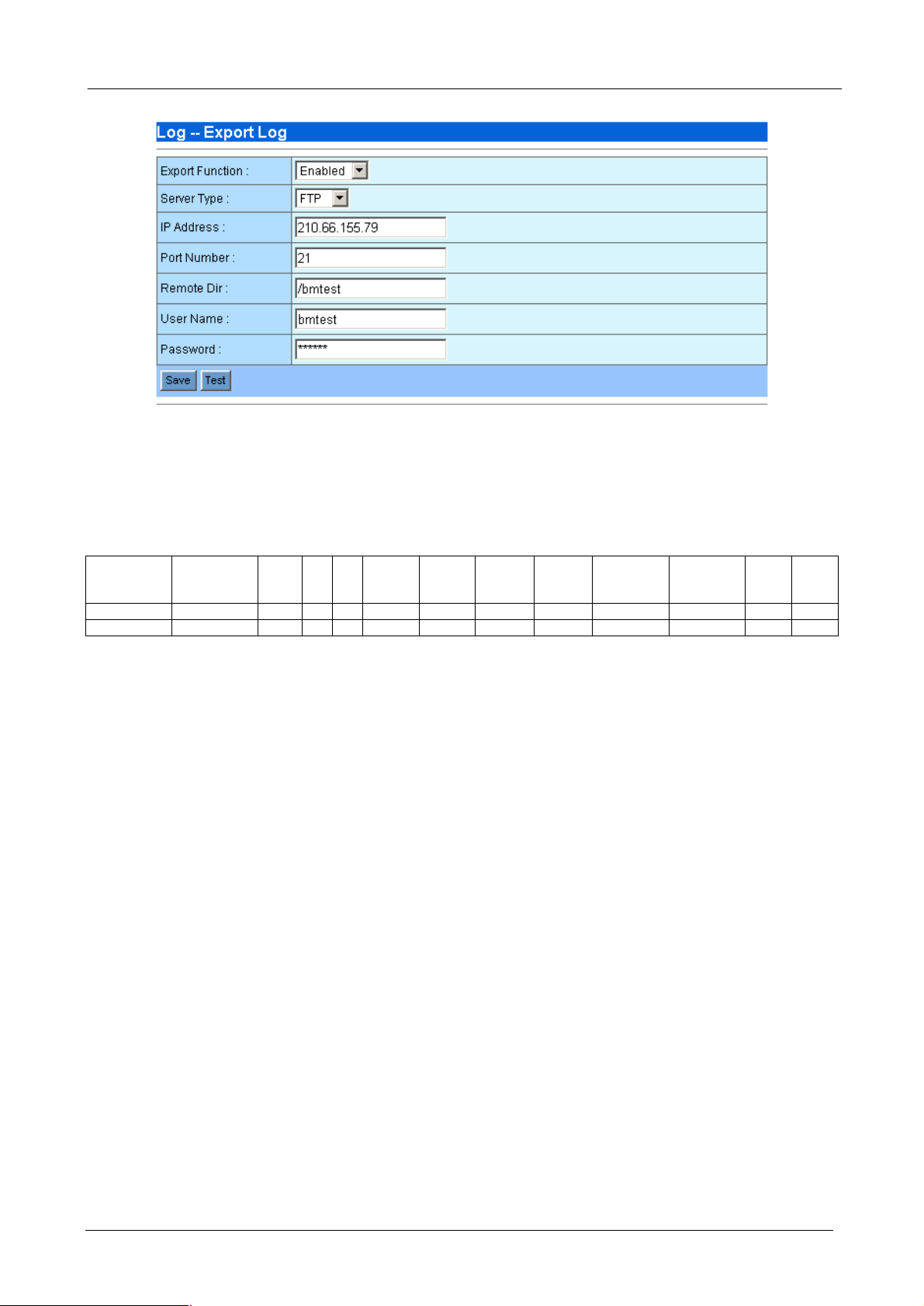
4.3.10 Log – Export Log
This function allows you to send all the session statistics to a FTP server. The log data which compressed
with tgz is sent to FTP server every 5 minutes. This data is suitable for you to make your own analysis and
even billing. The following parameters are required:
¨ Export Function: Enable or disable the export function.
¨ Server Type: Choose the server type as FTP or FTPS. FTPS is FTP with SSL security which is more
secure than FTP. Please make sure your FTP server also support FTPS before choose FTPS.
¨ IP Address: The IP address of the FTP server.
¨ Port Number: The TCP port number used for FTP communication. The default port number for FTP is
21.
¨ Remote Dir: The directory used to store the log data. Please make sure you have created this directory
on the FTP server before make test.
¨ User Name: The user name used to login to FTP server.
¨ Password: The password used to login to FTP server.
¨ Save: Press “Save” button to save above configurations.
¨ Test: Test the connection status to FTP server. If the server is on-line and the remote directory, user
name and password are all correct, the Bandwidth Manager will upload a file named “test_upload” to the
remote directory and a small window will pop-up with message of “Server is ready”. Otherwise, it will
show “Can not connect to server”.
- 35 -
Page 40
BM-2002 Bandwidth Manager User’s Manual
Once you click “Save”, the Bandwidth Manager will start to export the logo data to FTP server every 5 minutes.
The file name format of log data is “year-month-day-hour-minute.txt.gz”. For example,
2003-05-21-19-15.txt.gz. The minute represent the start time of the log data. Each log file contains many
connection session for the 5 minutes. The data format is as the following with an example:
First
Host
Last
Packet
Host
Host1 Host2 Protocol Port1 Port2
192.168.001.040 192.168.002.137 6 139 3982 184023 5164128 2461 3729 01:40:02.9531 01:45:01.9304 2 2
192.168.002.137 192.168.001.203 6 4109 22 52932 190218 330 355 01:40:25.7275 01:45:02.1453 2 1
Received
Bytes 1
Received
Bytes 2
Received
Packets 1
Received
Packets 2
First Packet
Time
Last Packet
Time
Packet
¨ Host1: Host 1 IP address, eg: 192.168.001.040
¨ Host2: Host 2 IP address, eg: 192.168.002.137
¨ Protocol: Network connection protocol, 1=icmp, 6=tcp, 17=udp, 0= other non-TCP/IP packets.
¨ Port1: Port number used by host 1, eg: 139
¨ Port2: Port number used by host 2, eg: 3982
¨ Received Bytes 1: Total number of received data by host 1 in unit of bytes
¨ Received Bytes 2: Total number of received data by host 2 in unit of bytes
¨ Received Packets 1: Total number of received packets by host 1
¨ Received Packets 2: Total number of received packets by host 2
¨ First Packet Time: Time the first packet pass through the Bandwidth Manager. This is the time the
session start. The time format is HH:MM:SS.SSSS which HH is hours, MM is minutes, and SS.SSSS is
seconds with precision up to 1/10,000 seconds.
¨ Last Packet Time: Time the last packet pass through the Bandwidth Manager. This is the time the
session complete. The time format is HH:MM:SS.SSSS which HH is hours, MM is minutes, and
SS.SSSS is seconds with precision up to 1/10,000 seconds.
¨ First Packet Host: 1 mean Host 1 send the first packet, i.e., host 1 start the session. 2 mean Host 2
send the first packet, i.e., host 2 start the session.
¨ Last Packet Host: 1 mean Host 1 send the last packet, i.e., host 1 complete the session. 2 mean Host 2
send the last packet, i.e., host 2 complete the session.
- 36 -
Page 41

BM-2002 Bandwidth Manager User’s Manual
- 37 -
 Loading...