

Page 1
THE GREATEST POWER AMPLIFIERS IN THE UNIVERSE
The
Big
Bang
Zetar
Vortex
Nebula Ouadra
DESTI
youR4
Page 2
Page 3
Welcome
to
a
neur
planet
mmml
Introducing five incredible new amplifiers, all made in the United States of America. Orbiting Planet Audio are
three high-power 2-Channel amplifiers, one high-power 4-Channel and a monoblock amplifier.
I
This series of Planet Audio amplifiers has been built and tested to the highest standards. These amplifiers follow a
"Zero Compromise'' design philosophy. The built-in features permit them to accommodate almost all installation
situations. The heat sinks are truly massive, weighing almost twice as much as would be required for their power
categories. When you review the features and specifications for these amplifiers, you will agree that these new
amplifiers from Planet Audio set a new standard of excellence for car audio performance.
Planet
Audio.
Page 4
Pourer
a
Fully regulated, Pulse-Width Modulated supply assures constant
battery voltages between 11.5~ and 16v
Optically-isolated (from internal
#
High-ent MOSFETS
Suoolu
..
.
tn
the push-pull output stage
amplifier
drcuitry)
remote input
power
delivery at all
Audio Amolifiers:
Front end preamplifiers accept up to 8 volts of signal input
a
One-band parametric equalizer allows more flexibility for tailoring the response of the
system
Low
pass
wh
pass crossover on Nebula, Vomx, Zetar and Quadra features a 1ZdBloctave Butterworth
Low $ass crossover on The Big Bang features a 24dBtoctave Linkwitz-Riley slope
J3igGass crossover on The Big Bang features a 24dBloctave Linkwitz-Riley slope. The
crossbver frequency range
.
',
!
Continuously-variable phase control for time-alignment of speakers, permitting adjustments
ipspeaker placement
.
True line outputs
multi-way systems
The Big Bang features a unique, anti-phase mono line output to accomodate bridging of
two Big Bangs for up to 2 Kilowatts of power
The Big Bang has a multi-pole switch which allows three modes of operation:
I#
crossover on Nebula, Vortex,
in
Preamo
is
such that it can act as a subsonic filter.
Nebula, Vortex, Zetar
Circuits
7
I
Wr
and Quadra features an 18dBloctave Butterworth slope
and
Quadra
allow for connection of other amplifi
Normal,
signal path
Direct
controls but keeps the parametric equalizer in the circuit
Bridged Mode,
amplifier, with no processing whatsoever. This mode
exclusively for bridging two Big Bang amplifiers together.
Audio Amplifiers:
Thermally-compensated constant-current arcuits, which are optically-driven from the
power supply, control the front end differential stages. These
amplifier thermal
of the input differential amplifiers.
Locally-degenerated, fully-complementary Class A differential amplifiers have very wide
bandwidth, before global feedback is applied.
Fully-complementary Class A voltage amplifiers are locally degenerated, and drive the
output stages with very low impedance drive.
Output stages are wide bandwidth, compound-emitter followers, utilizing high current,
bi-polar transistors.
which allows utilization of the complete low pass
EQ,
which bypasses the low pass, high pass and phase
which sets up the amplifier as a "true" power
Power
drift,
increase common mode rejection ratio, and lower the distortion
Amplifier
Circuits
circuits
is
used
control and minimize
Page 5
5
'in
4.
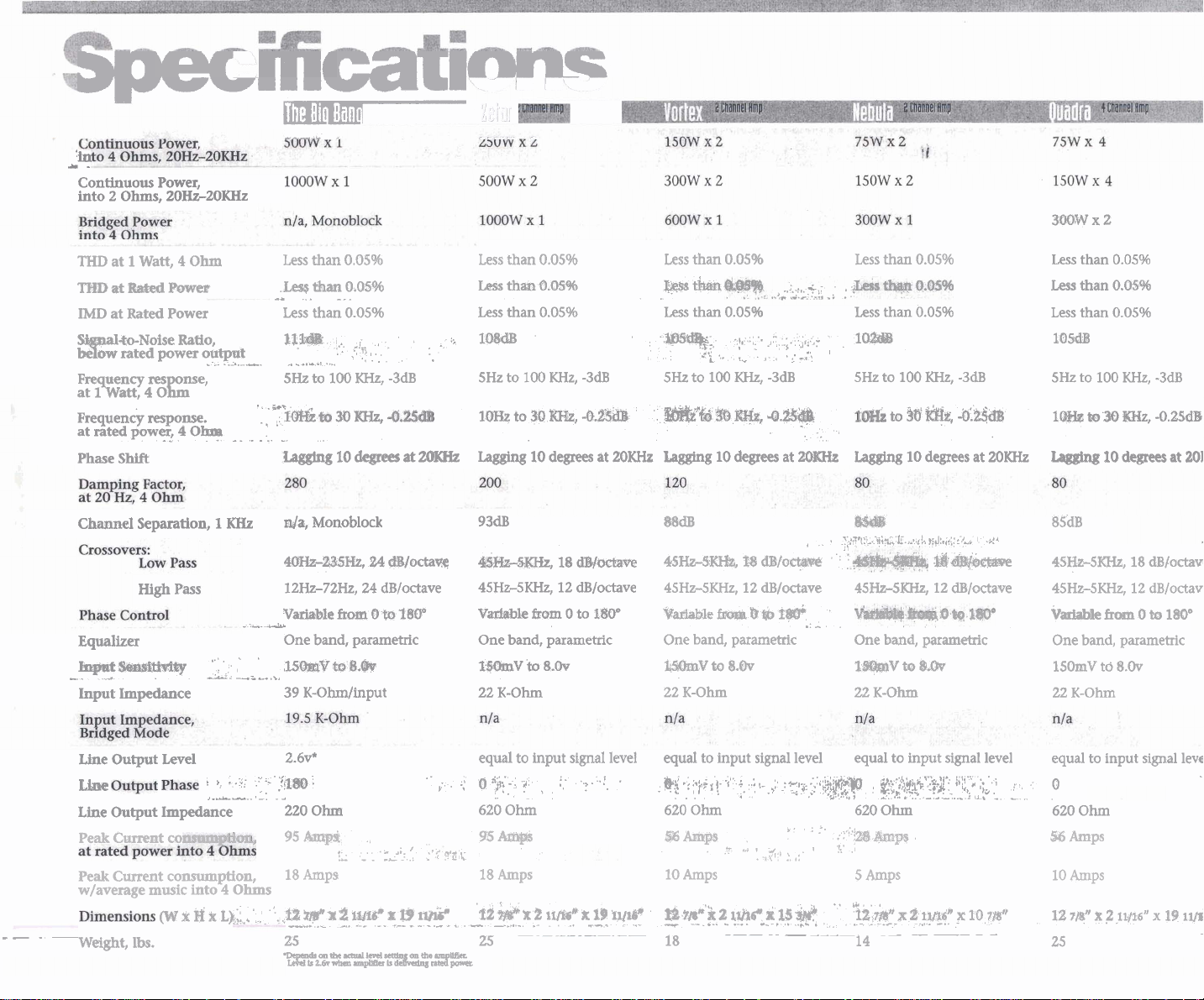
Continuous Power,
into
q;~kq
-
2
Ohms,
20Hz-ZOKHz
The
Bi
Ban
ral
;L-
3MW
x
2
THD
at 1 Watt, 4 Ohm
at^^^
IMD
at Rated Power
to-Noise Ratio,
w-
ow rated power output
at
Tn?
1
att
4
mgrnel
0
Frequency
atratedpower,40-
Phase
Channel
response.
A
-
Shift
Separation, 1 KHz
High
Pass
Equalizer
Wt-E-
->
Input
Impedance
Less
than
.lm$
tbn
--
.
Less than
m4%
-
.......
-.....
--A
.-
&--
-=--...
.-
..
5Hz
to
'
----
I&
"'
Lagging
da,
Monoblock
40%-23!SHz,
12Hz-72Hz,
Variable
One band, parametric
'
,UWVtoB+fiW
39 K-Obdtnput
-
..
,.
..,
100 KHz,
tom,
10
fbm
0.05%
0.05%
-
0.05%
.,,,
,
.
x),
,
.
degrees at
24
24
dlloctave
0
to
-3dB
20KHz
&/octaW
1BCP
,
Less than
Lesa
Less than
IO8d-B
SHz
10%
Lagging
thaa
to
100
to
0.05%
O.QS%
0.05%
30
10
93dB
4S&-dK&,
45Hz-SKHz, 12
V&bk
&om
One band, parametric
1mv
to
22
K-Ohm
KHz,
-3dB
m,
-@a&
degrees at
18
dE/W@Vt?
dB/octave
0
to
8Shr
180"
20KHz
Less than
0.05%
Less than
~~
Less
than
0.05%
mM&-,
5Hz
@d&td
Lagging
,*.
'
,.
to
100 KHz,
.)
.
1,
#@
El&,
10
degrees at
...
,-
,
-3dB
4.%&&
;.
A$.,:
','-*%
201Mz
88dB
45W§~,
45Hz-5KHz, 12
'yktariable
One
l&knV
22
K-Ohm
D
&to-
dB/octave
~gcaraaplrf~
T*
band, parametric One band, parametric
to
8.h
.,
.
.
4
7
..
.
Less
than
1W
SHZ
to
100 KHz,
to
%
Lagging
&St@
'.S'l'-
1)
'
45Hz-5KHzI 12
tB@&lY
22
Xi&
Il
to
K-Ohm
10
,.*g!%
0.05%
0.05%
&I?,
degrees at
fi$m4,:',<wc
d@&k%iSv
dB/octave
8Bv
-3dB
-bk$TB
20KHz
-24
Less than
Less
Less
105dB
5Hz
1-
Lagging
85dB
45Hz-5;KHzl 18
45Hz-5KHz, 12
Variable
than
than
to
100 KHz,
ho
30
10
fmm
0.05%
0.05%
0.05%
KW,
degrees at
dB/octave
dB/octave
0
to
-3dB
-0.25db
1%)"
One band, parametric
150mV
td
8.0~
22
K-Ohm
20KHz
--
Line Output Level
Lime
Line Output Impedance
Peak Current
Peak
Current consumption,
w/average music
-
-
Weight, lbs.
co
(w
r
into
B
'
',
. .
,.A-
4 Ohms
r
L),::.,
2.6v*
"'
-
-.
"
.fit@@
-
.
.
2
220
Oh
95
Amps
18
Amps
'.
vs
XM
x
--
.-
25
W~%L~&~~nFpolk
L
2
-..
---L
i1/16~
,.-
--
"
x
"
---..
f
19
.
....
,..
,
.
IVY~
-.-
.,
equal to input signal level equal to input signal level equal to input signal level
.
0
y;.-;
.,
&
620
56
18
'12
-
25
.?,
.
,.
... - .
Ohm
~~
Amps
kx
2
A
.,.-
.-
,
:
.
II/I%~
..
.
.
.>..
.
,
'
x
19
---
.
111le~
-
.-
&i
.;
:-,.;
,.j.
.;..;
,,;
:-
,,
,
-,..-
..
,
.
,
.
,
....
620
Ohm
am$
10
Amps
I*
tl~_"'+~
-
18 14 25
,
(.
9
.
-3
qm<x>~
,
.
'
.
,,
..
4.;.
,
:
0:
+
- - ---
:;,;.J#r$p
../
...
'.
8
,,
620
I.
.
:"'a
7;
8
5
Amps
-.
U.
i_ayg'-x
o..;!;&,'
j
$-l.:l:l..
;
:
..:...
:...
Ohm
bps
.
.
2
-
-
--
~l
;;y
x
-
-
'.
,
;
:a.
10
-
'
.
:
--
_.
IU~"
-
equal to input signal level
0
. ....
620
Ohm
%Amps
10
Amps
12
7Bn
x
2
1yt6"
.
x
19
lime
--
Page 6
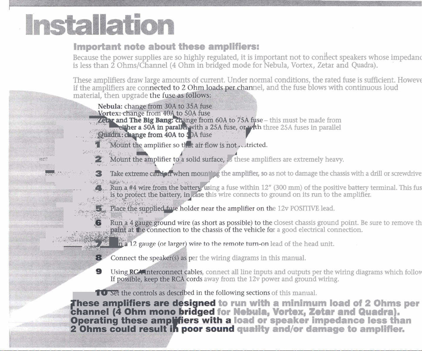
important note about these
amplifiers:
Because the power supplies are so highly regulated, it is important not to condect speakers whose impedance
is less than
2
Ohms/Channel(4 Ohm in bridged mode for Nebula, Vortex, Zetar
and
Quadra).
These amplifiers draw large amounts of went. Under normal conditions, the rated fuse is sufficient. However,
if
the amfilifiers
are
con
nel, and the fuse blows with continuous loud
material, then upgrade
Lo
50A
fuse
Leti
.
,
,,
,
'I'
-
3
-
~
*
q'
,,.
>:!:,
7
. .
,,
.
.
,L
,
,
2
.%
,
.
!
z,,,
,
2-
3
.
,
-,
.
-
.<4
,
lc.
,;
..
'..
!$
.t;*?Y
,
"
%
.?I
!;*,<>yL;i?:
,
%
.
>$;$;'*.y
.
r:3.q,
','P
&F:YIT:
7G.,vV
-@@b:
.P
'5
5
.
c-7
.
u&&f!+
.
'
>i
Mobnt the
..'
2
,
Take
-
.2,i.41i:.
:..
$114
is
,'I
'.*
'
,Racefie supplied
,
>
Run a
-
,",,J
'"
$;
a
.
i
extreme
'
.
a
#4
to
protect the battery, i5
-,
,..,;>I?:,~-
.,
.
*
4
ai
<
:,
..+$L,
na
i
C~UF~LI
wire
fromthe b$tl:erZ
,
.
I.
1-
fill
nge from 60~,t0
with a
j~
.,t air
a
solid surface,
r
fuse
flow
25A
when mount-'--
I
Ksing a fuse
*
Kse this wire connects to ground on its
is hot
75k
fi
-
this must be made from
fuse, or
A
i
Fthese amplifiers are extremely heavy.
three 25A fuses in parallel
-4
as not to damage the chassis
,yithin
12"
(300
e 12v
mm)
of the positive battery terminal.
run
to the amplifier.
POSITIVE
lead.
closest chassis ground point. Be sure to remove the
r a good electrical connection.
lead of the head unit.
with
a
drill
or screwdriver.
This
fuse
,.,.
,
interconnect
sible, keep the
I
u
3et
the
controls as descr
RCl
rhese amplifiers are de
(4
channel
Ohm mono
Operating these ampl"'
2
Ohms could result
i
cr the wiring diagrams
,
conned
away from the
to
E
for Nebula,
in
this manual.
all
line inputs and outputs per the wiring diagrams which follow.
12v power and ground wiring.
of this manual.
run with
load
qwalRy
a
minimum
Vorkx,
or speaker
mmdtw
lord
ktar
and
impedance
damage
of
2
Quadrs
ieoo
ta
antpHfler.
Ohms
d;
an
per
Page 7

The
Bio
Bano
Single flmplfier Sqsteiii
to INPUTS OF FRONT
SATELLITE
OVrPVTrof
(sold
from
HEAD
UNIT
Y-ADAPTORS
separately)
I I
REAR
to
INPUTS
OF
SATELLITE AMPLIFIER
REAR
/-
Set
Amp Selector
"Normal" or "Direct
Switch
to
EQ"
NOTE:
The
++
and
-
-
connections are duplicated. Use
+
either
and -for your connections.
speaker
to
REMOTE
NRMN
from
HEAD
wrr
Amplifier
Selector switch to either Normal or Direct
If
If
Note:
The amplifier may get its input signal from a head unit or equalizer's subwoofer output.
Use of the Line Out connectors on the Big Bang rear panels may not be necessary in all systems.
Two terminals are provided for each
to these terminals, be sure the total impedance is at least
Settings:
EQ
set
to
Normal
...
set
to
Direct
The high frequency amplifier(s) are fed their input signals(s) from the same front and rear signal source as the Big Bang.
all front panel controls
EQ.
..
only
the parametric and level controls will affect the signal
(+)
and
will
affect the signal
(-)
speaker connection to accomodate large gauge speaker wire. If multiple loudspeakers are connected
2
Ohms. If you are not sure of the total impedance, consult an installation specialist.
GROUND
777
m
WOOFER
MINIMUM
IMPEDANCE
7
nHMCI1
SYtAKEK
IS
1
Page 8

Page 9

Page 10

Page 11

Page 12

Page 13

MINIMUM SPEAKER
IMPEDANCE
2
OHMS/CHANNEL!!!!
IS
Amplifier
Set
If speakers are
If speakers are
If
speakers are subwoofers.
Settings:
all
EQ
Phase and level controls to suit your musical taste.
@I1
range..
.
Set Selector to Flat
midhigh
Set Selector to High Pass, and set High Pass crossover to suit your preferred frequency response.
frequency
drivers
...
..
Set Selector to
Low
Pass, and set
Low
Pass crossover as desired.
Page 14

Page 15

Page 16

Hints on setting
the
controls
on
the Parametric Equalizer
The Parametric Equalizer on this amplifier series differs from "conventional" equalizers
boost or cut is applied is variable, as is the
(Fo),
a fixed center frequencies
with the
"Q"
(or bandwidth). Conventional equalizers only allow the boost or cut to affect
"Q"
is fixed at a certain value
as
well.
Very
(High
nmrow
"Q")
bandwidth
selected
in
that the frequency at which the
Modemte
,-
boost
Center
applied
frequency
set
to
High
Q
scenario:
Boost
EXAMPLE
of
13dB
or
#2
more occurs
in
the
93Hz-107HL
range
Page 17

mplifier will
3t
power up*
,
totection
ED
comes on
c
hen the
nplifier is
pwered Up.
Check for good ground connection.
Check that Remote Input (turn-on)
at amplifier has at least
Check that there is battery power on
+
terminal.
the
Check all fuses.
Check that'hotection LED
If it is lit, shut off amplifier briefly
and then
Check for short circuits on speaker
leads.
~um
head unit to prevent overdriving.
Remove speaker leads, and reset the
amplifier. If the Protection LED still
comes on, then the
repower it.
down the volume control on the
3
volts DC.
is
not lit.
amplifier is faulty.
High hiSs
in
speakers.
High squeal
noise from
speakers.
Distorted
sound
Disconnect
amplifier($ - if hiss disappears, then
plug in the component driving the
-ampli£ier and unplug its inputsyIf
disappears, go on until the
faultylnoisy component is found.
i)
It is best to set the amplifier's input
level as insensitive as possible. The
best subjective
this way.
level from the head unit as possible.
Thisis almost always caused by a
poorly-grounded RCA interconnect.
Check that the Level control(s) is set
to match the signal level of the head
unit. Always begin at the lowest
setting.
Check that all crossover frequencies
have been properly set.
Check for short
leads.
all
HCA
inputs to the
SIN
Try
ratio is obtainable
to drive as high a signal
circuits
on the speaker
hiss
0
output.
,w output.
nly one
~annel
orks.
Check that all fuses are
Check that amplifier is properly
grounded.
Check that Remote Input (turn-on)
at amplifier has at least
Check that RCA patch cords are
plugged into correct inputs.
Check speaker wiring.
Reset Level Control.
Check Crossover Control settings.
Check RCA interconnect cables.
Check speaker wiring.
OK.
3
volts DC.
Amplifier(s)
gets
very hot.
Engine noise
(static type)
-
Engine noise
(alternator
whine)
Check that the minimum speaker
impedance for that model is correct.
Check that there is good airflow
around the amplifier. In some
applications, an external cooling fan
may be required.
This is caused primarily by poor
quality
RCA cables picking up radiated
noise. Route
power wires, and use only the best
quality cables.
Check that the speaker leads are not
shorted to the vehicle chassis.
Check that the RCA grounds are not
shorted to the vehicle chassis.
Check that the head unit is correctly
grounded.
all
RCA cables away from
 Loading...