

Page 1

Page 2
t
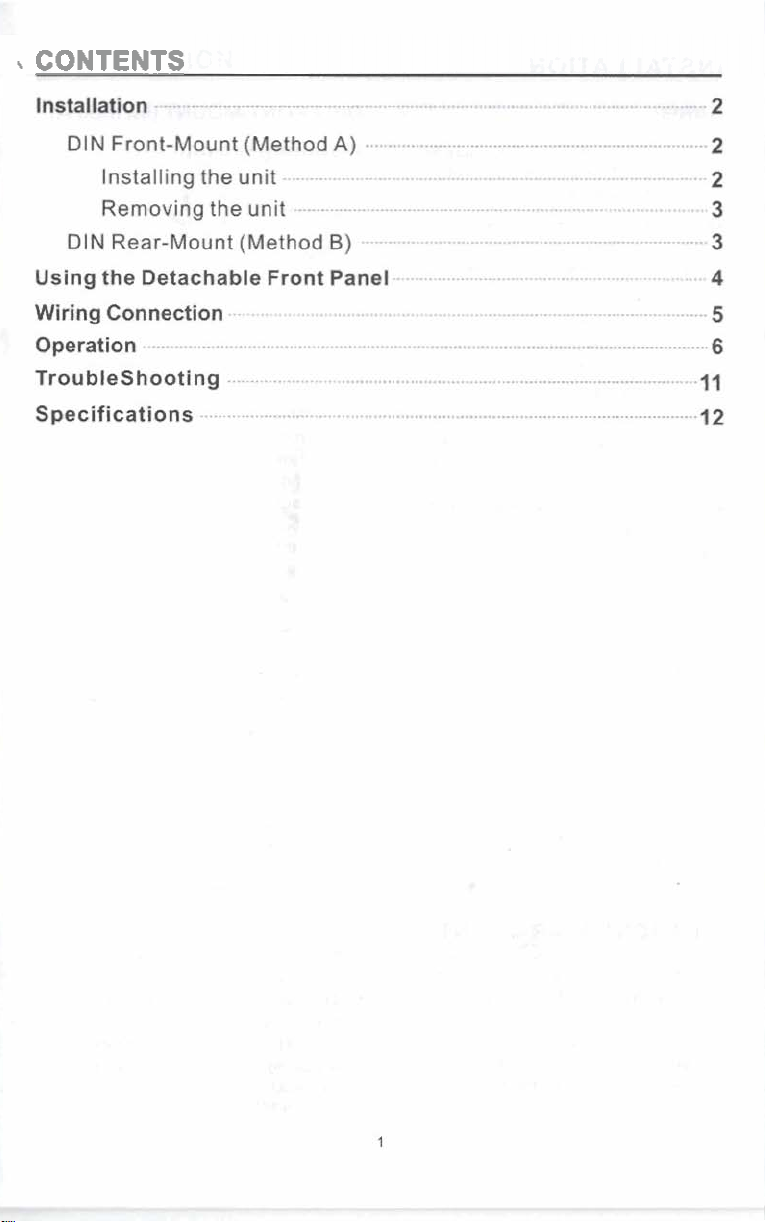
CONTENTS
Page 3
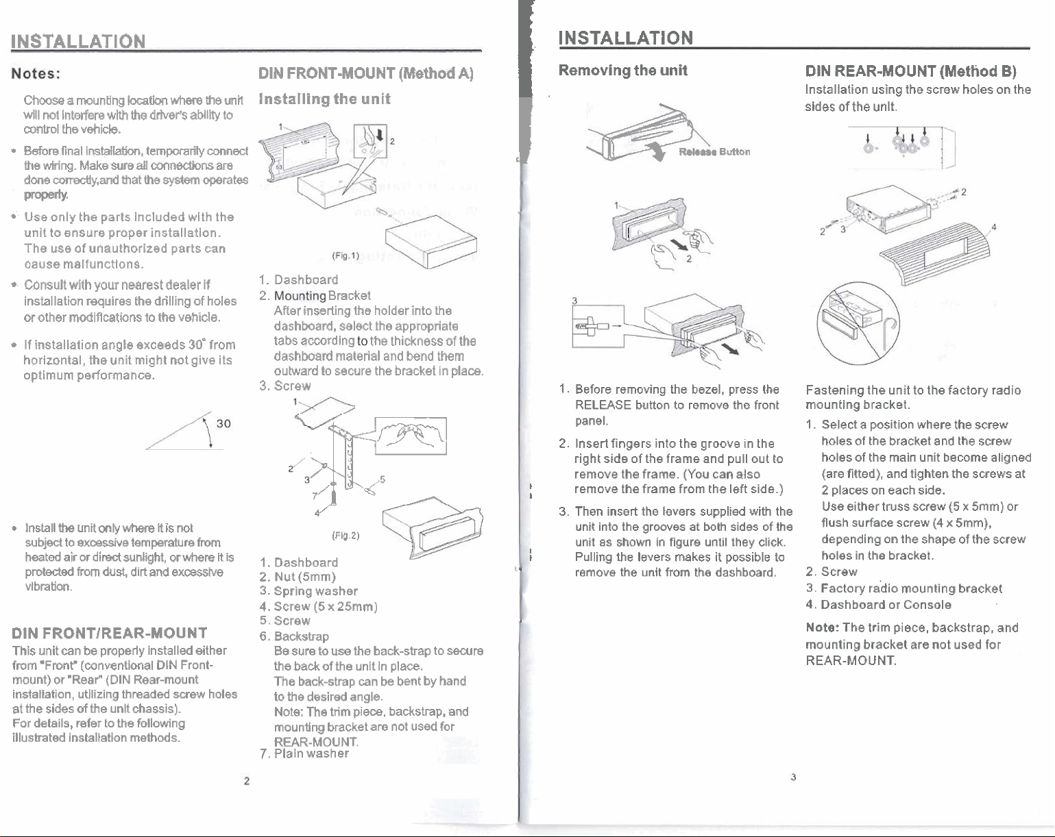
INSTALLATION
ChmseamuntlngloGatlWlwharetheunil
wlll
not
hWem
cwrtrol
the
-re
final lmtallahn, tempwarily
the
wking.
done
mmdy,artd
Use
only
unit
to
ensure proper installatlan.
The
use
oause rnalfunctlons.
Consult
installatiin requires
or
other
If installation
horizontal,
optlmum
Install
the
subid
to
heated
air
proteded
vibration.
DIN
FRONTIREAR-MOUNT
Thls
unit
can
from
'Front"
mount)
or
installation,
at
the sides
For
details,
illustrated instaltatlon
wlth
the
drhrePs
vehicle.
Make
sure
&I
mnWons
that
the
the
parts Included wlth the
of
unauthorized parts
with
your
nearest
the
drilling
modlflcartions
angle
the
to
the
exceeds
unit might
performance.
unit
only
where
It
excessive
or
from
be
(wnventlonal
"Rear"
utilizing
of
refer
dim
sunhght,
dust,
properly
(DIN
threaded
the
unlt chassis).
to
the
temperature
dirt
and
Installed either
DIN
Rear-mount
following
methods.
aaMlhy
system
dealer
of
vehicle.
30'
not
give its
is
nat
frwn
or
where
ewsslve
Front-
screw
to
mnect
are
mtes
can
If
holes
from
R
holes
DIN
FRONT-MOUNT
!n~tallin~the!~nit
I.
Dashboard
*.
After
dashhard, select
tabs
dashboard
outward
3.
Screw
Bracket
inserting
awrding
material
to
secure
the
31:"
/-
(Flg.2)
Is
1.
Dashboard
2.
Nut
(Smrn)
3.
Spring
washer
4.
Screw
(5
x
25mm)
5.
Screw
6.
Backstrap
Be
sure
to
use
the
the
back
of
the
unlt In
The
back-strap
to
the
desired angle.
The
Note:
mountlng bracket
REAR-MOU
7.
Plaln
washer
trim
NT.
can
piece,
(Method
holder
into
the
appropriate
the
thickness
and
bend
the
bracket in place.
back-strap
place.
be
bent
by
backstrap,
are
not used
the
of
them
to
secure
hand
and
for
A)
the
INSTALLATION
I
Removing
I.
I
1.
2.
I
1
3.
I
t
the
unit
Button
Before removing
RELEASE
panel.
Insert fingers into the groove
right
side
remove the frame.
remove the frame
Then insert the levers supplied with the
unit into the grooves at both sides
unit
as
shown in
Pulling
the
remove
the
the
button
to remove the front
of
the
frame and pull out
(You
from
figure
levers
makes
unit
from
bezel, press
in
the
can
also
the
left side.)
until
they
click.
it possible
the dashboard.
the
of
to
the
to
DIN REAR-MOUNT
Installation using the screw holes on the
sides
of
the
unlt.
Fastening the unit to the factory radio
mountlng bracket.
I.
Select a position
hales
of
the bracket
holes of
(are
2
Use
flush
depending
holes in the
2.
Screw
3.
Factory
4.
Dash
Note:
mounting
REAR-MOUNT.
the
main unit
fitted), and tighten
places on each side.
either truss
surface
screw
on
bracket.
rho
board or Console
The
trim piece, backstrap,
bracket
(Method
where
and
become
screw
(4
the
shape
mounting
are
not
the
screw
the
the
screws
(5
x
5mm)
x
5mm),
of
the
bracket
used for
B)
screw
aligned
at
or
screw
and
Page 4

USING
THE
DETACHABLE
FRONT
PANEL
:
WIRING
CONNECTION
DETACHING
Press
the
RELEASE
from
rlght
slde
Grasp
the
right
remove
Immediately
case
for
It.
safe
ptaca
and
of
side
THE
button
the
of
fie
dean
FRONT
hebd
the
front
storage.
to
release
untt.
panel
panat
PANEL
the
and
pull
in
its protective
panel
to
~RELEASEw~tMhont~
...
IONiTION
SWITCH
REARLM
SPEAKER
MAIN
(8.1
GAEEFUBLA
K
UNIT
Rch
RED
Ich
WHITE
SUBWOOFER
CABLE
RUh
RED
Lch
WHITE
RUi
RED
Lch
WHITE
REAR
Rch
*,
. .
REINSTALLING
Push
the
front
panel
should
hear a
"click"
NOTE:
properly,
be
display
occurs,
front
If
the
the
impaired,
may not
press RELEASE
panel.
panel
function
and
become
THE
Into
fails
some
FRONT
the
maln
to
lock
of
some
segments
illuminated,
and
relnstail
PAHEL
body.
Into
positlon
controls
of
the
If
You
may
this
the
prash
panel
hb
meln
LUH
untU
you
M
s
"W.
AUXILIARY
This
CD
Receiver features
An
external
connected
audio
via
INPUT FEATURE
an
Auxiliary
source
such
as
a
thls
Input
lack.
Input
portable
jack
audio
on
the
player
back
or
a
side
DVD
of
the
unit.
player may
be
Page 5

Page 6

Page 7

Page 8

SPECIFICATIONS
CD
PLAYER
Slgnal
to
Noise
Ratio
Channel
Frequency
Separation
Response
:
More
:
More
:
20
than
than
Hz-
60
60
20KHr
dB
dB
RADIO
Frequency
IF
Sensitivity
Stereo
Separation
GENERAL
Tone
Controls
-
Bass(at
-
Treble
Maxlmum
Power
Current
Dimensions
Weight
100
(at
Output
Supply
Consumption
Coverage
(SIN
=
30dB)
Hz)
10
KHz)
Power
Requirements
FM
:
87.5
to
107.0
:
10.7
MHz
:3
crv
:
530
dB
:f
IOdB
:t
lOd8
:
SO
Watts
x
4
:
DC
12
Volts,
Negatlve
:
8
Amperes
:
178
7-x85/is"x2-
:2kg
4.4
Ib
0
{max.)
x
161
MHz
(D)
x
50
Ground
(H)
mm
 Loading...