

1
1,
I
-.:
Welcome
.i'$
'
?
'6
$4
Introducing six new amplifiers, all made in the United States of America. Orbiting Planet Audio are three 2-Channel
P502 and PI002 feature a pair of individually-adjbstable high and low pass crossovers, a low frequency variable
-:
boost control, independent routing switches for both the amplifier and line out sections. in addition, the low and
to
a
new
a
pair of 4-Channel amplifiers, and a 516 Channel unit.
crossovers can be cascaded to form a bandpass (midrange) section for use in triamplified systems.
plane
I
I
*
.q
of vacuum tubes as its active elements.
has identical features to the above amplifiers, with one addition - the main preamp features a pair
LS
4
One of the four channel amps, P704, has three sets of crossovers, two high pass and an
-1
course, all are independently adjustable. Selector switches allow both pairs of channels and the line output to pass
1
flat frequency, high and low pass signals.
+A
crossover.
#
.
HVT754 is identical to the P704 with the addition of the vacuum tube front end.
--7Sv
I
The
P706
One pair of channels is controlled by a high pass crossover. The second pair is controlled by both a high and a low
pass crossover, so a
is an extremely flexible amplifier. Four crossovers allow this unit to perform many different functions.
bandpass function can be achieved. The last pair have a 24 dB/octave low pass crossover.
A
I
18
dB/octave low pass. Of
low frequency variable boost control is "married" with the low pass
I
1
I
Planet
Audio.
/
021tput
-9
Map10
hllo40hnu
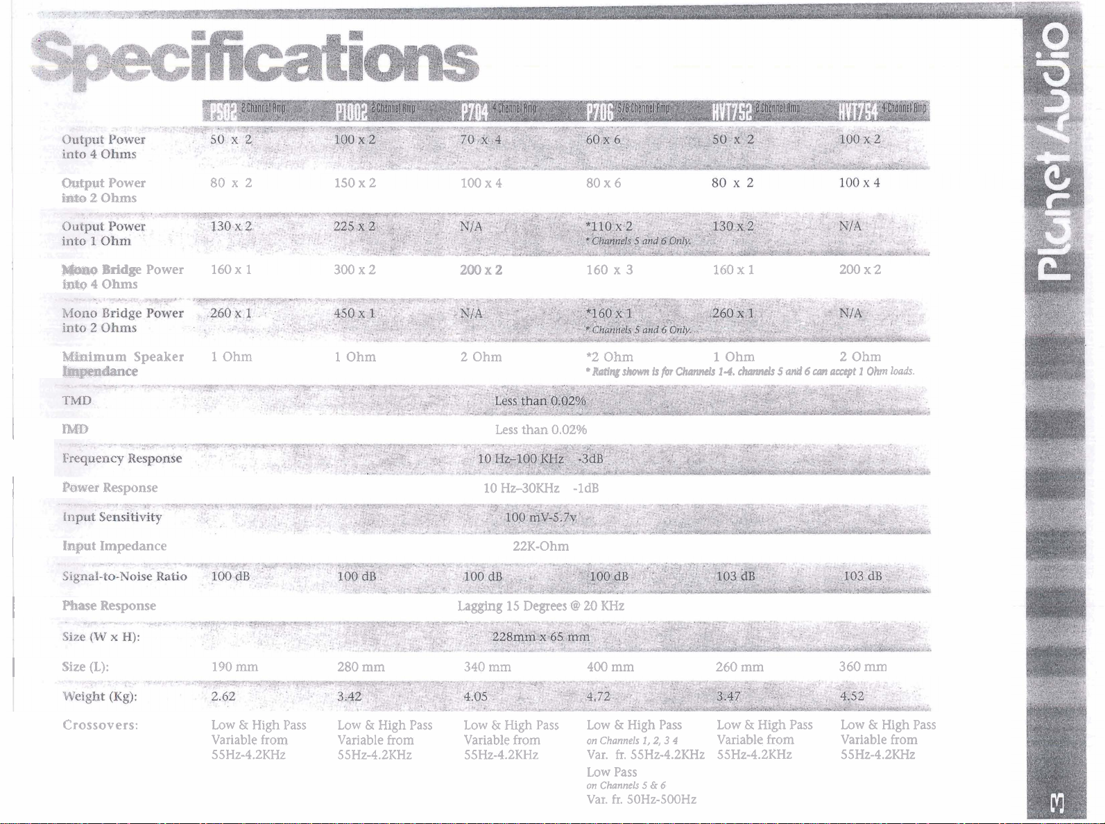
Rower 80 x 2 150 x 2 100 x
2
Ohms
Bridge Power 160
x
4
1
300x2 160 x
80 x 6
3
160~
1
200 x2
I
1
I
I
I
I
I
Mknimum
EMD
Paw@
Response
input
Impedance
mase
Response
Size
(L):
Crossovers:
Speaker
1
Ohm 1 Ohm 2 Ohm *2
Less than 0.02%
10
HZ-30KHz -1dB
22K-Ohm
Lagging
190 mm 280 mm 340 mm 400 mm
Low & High Pass
Variable from Variable from
55Hz-4.2KHz 55Hz-4.2KHz
Low
&
High Pass
Low
Variable from
55Hz-4.2KHz Var. fr. 55Hz-4.2KHz 55Hz-4.2KHz
&
15
Degees
High
Pass Low & High Pass
Ohm
Rating
@
20 KHz
on Channels
Low Pass
on Channels
Var.
shown
fr.
is
for
Channels
1,
2, 3 4
5
&
6
50Hz-500Hz
1
Ohm
1-4.
ciKuvlefs
5
and
260 mm
Low
&
High
Pass Low & High Pass
Variable from Variable from
6
can
accept 1 Ohm
2
Ohm
loads.
360
mm
55Hz-4.2KHz
Find a suitable location in the vehicle to mount the amplifier.
1
2
Make sure there is sufficient air flow around the intended mounting location.
3
Bolt the amplifier to the mountj--
--.-Fn-n
A
kpoint on the chassis of the car.
ngth. Use
#8
wire.
rlect the remote termi,
empty fuse hol
kuality cable
Lis no
7
t
fuss
battery fuse holder(s).
before powering up.
of the head unit using
")
of the battery and run a
#14
wire.
#8
or
1
connection to the
cables (each with its own
r-
ble from the fuse holder at the battery to a
am~lifier's location.
A
using high-quality
:
least
frequ
up, set the volume control on the head unit to about the
set all the amplifers' level controls for maximum sound
itive positions and set all crossover
or position.
RCA-RCA
cables.
"BATT"
controls,
arious controls may
I
be
necessary to obtain the desired

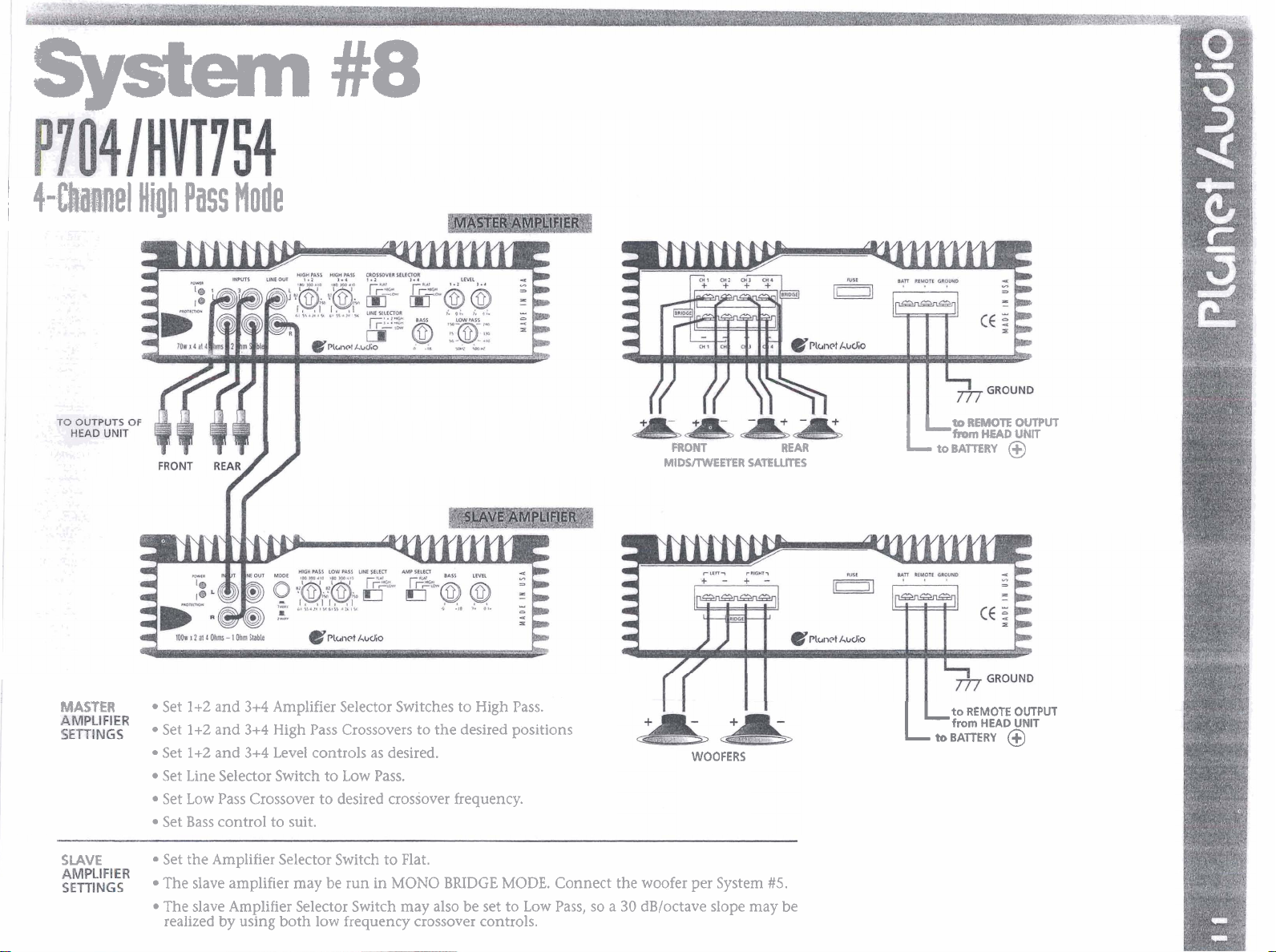
System
I
4-Cha81el
High
Pass
Node
#8
FRONT REAR
MlDSllWEETER
SATELUTE5
L
toBATIZRY
to REMOTE OUTPUT
hOm
HEAD
UNlT
@
WASTER
SLAVE
Set
1+2
and
3+4
Amplifier Selector Switches to High Pass.
0
Set
l+Z
and
3+4
High Pass Crossovers to the desired positions
Set
1+2
and
3+4
Level controls as desired.
Set Line Selector Switch to Low Pass.
Set Low Pass Crossover to desired crossover frequency.
Set Bass control to suit.
Set the Amplifier Selector Switch to Flat.
The slave amplifier may be run in MONO BRIDGE MODE. Connect the woofer per System
The slave Amplifier Selector Switch may also be set to Low Pass, so a
realized by using both low frequency crossover controls.
30
dB/octave slope may be
WOOFERS
65.
LL
to
from
to
BATTERY
REMOTE
HEAD
OUTPUT
UNlT
@

(
2-Channel
Mono
Bridge:
Flat,
High
or
lolu
Pass

Amplifier will
not
power
up*
Check for good ground connection.
Check that remote
at least 3v DC.
DC
termina1 has
Amplifier(s)
gets very
hot.
Check that the minimum speaker
impedance for that model is correct.
Check for speaker shorts.
Check that there is battery power on
+
terminal.
the
Check all fuses.
Check that
If it is lit-
k
&hen repower it.
Prn+nr+
-dm
h
all RCA inputs to the
a
aown low.
hcontro~
7
on the
e
noise
type)
Engine noise
(alternator
whine)
Check that there is good airflow
around the amplifier. In some
applications, an external cooling fan
may be required.
This is caused primarily
quality RCA patch cords picking
radiated noise. Route all
cords away from power W~TCS, and
only the best quality patch cords.
Disconnect all RCA inputs
amplifier
plug in the component dr~ving the
amplifier and unplug its inputs.
noise disappears, then repeat until
component that is causing whine is
found.
It is best to set the amplifier's input
level as insensitive as possible. This
also helps to reduce the audible
alternator whine.
-
if
noise disappears,
by
RCA
poor
to
the
tip
patcn
use
then
If
the
the
High squeal
noise from
speakers.
This is almost always caused by
poorly-grounded RCA patch cord.
a
 Loading...