

Page 1
Page 2
Page 3
Page 4
Page 5
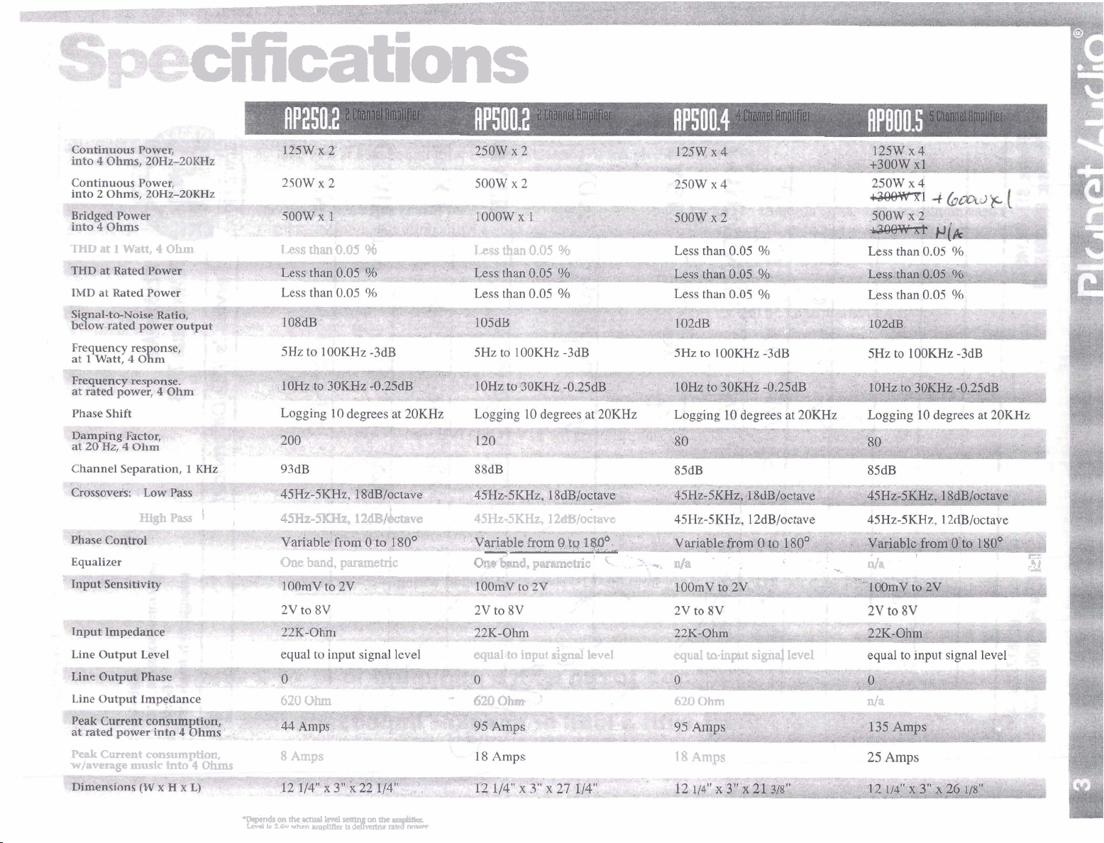
THD
at
1
watt,
cifications
4
ohm
Less thanO.05
98
Less
than
0.05
%
Peak
Current
wfavemge
High
pass
.
-
-..
.
consumption,
rn~sic
into
4
1
Ohins
,
*Depends
Ltd
4SHz-SKHz, 1 &B/o&ave
ariable
-
from
Q
t~
1$pO_
one
band,
parametric
equaltto
620
Ohm 620
8
Amps
a
the
~ual
b
2.6~
level
when
uqplLfkr~s
m
the
am
iBu.
rad!
input
Ggnal
kvel
equal
18
Amps
.
torinp~t
Ohm
,
sign4
i
level
.
:
-
da
C
a
n/a
Page 6
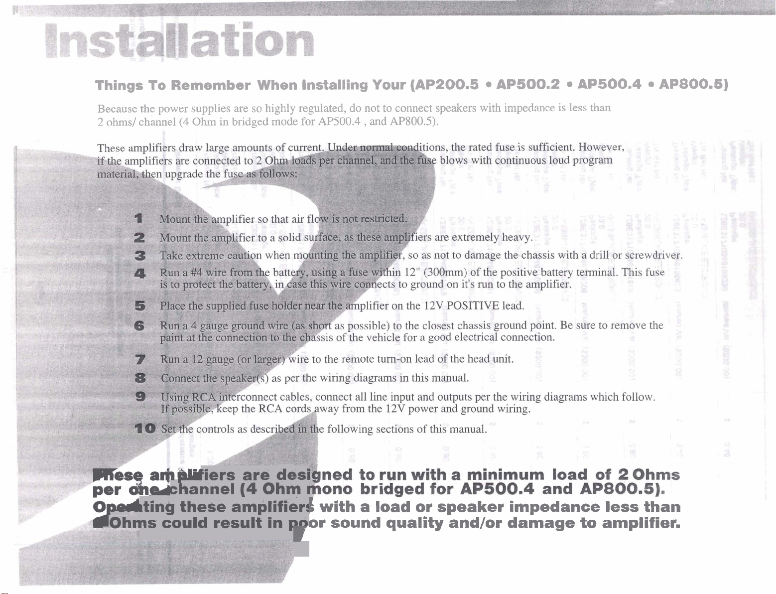
Things To Remember When Installing Your
Because the power supplies are so highly regulated, do not to connect speakers with impedance is less than
2
ohms/ channel
(4
Ohm in bridged mode for
AP500.4
,
and
(AP200.5 AP500.2 AP500.4 AP800.5)
AP800.5).
Iiers are desi
channel
I---
~ting these amplifier!
-
Ohms could result in
(4
Ohm
pal
I
1
with a load or speaker impedance less than
or sound quality and/or damage to amplifier.
r
Page 7

system
Tluo
Channel
Amplifier
Sqstem
#
1
RP2502
I
AP500.2
%PUTS
HEAD
UNIT
of
f?
)
to
REMOTE
WEL
CONTROL
Amplifier
Set
If speakers are
If speakers are
If speakers are subwoofers
Settings:
all
EQ
Phase
and
Nl
range
Set Selector to Hat
Set selector to
Set Selector to Low Pass,
midfigh
High
Pass,
level controls to suit
...
frequency
and
...
drivers
set
High
and
Set Low Pass Crossover as desired.
...
Pass
To REMOTE OUTPUT
your
musical taste.
crossover to suit your preferred frequency response.
+
I
I
SPEAKER
Page 8

I)'
-0
ZE
F=
0-
-cD
==
Lert
I
U
'I
R=
4.
=
Page 9

Page 10

Page 11

Four
ehannel
Amplifier
Sqstem
APS00.4
,
g
QI
I
-.:
0UTPU-p
HEAD
@IT
i
',
-.
.
-
8
..
.
.
of
,
..
.
:7
+
,
to
REMOTE
\
L
.
.
WR
.
.
COMWL
.
.
Amplifier
Set all
Lf
speakers are
Settings:
EQ
Phase and level controls to suit your musical
full
range..
Set Selector to Flat
If
speakers are
Set selector to
If speakers are
midhigh
High
Pass, and set
sub
woofers
frequency drivers
Set Selector to Low Pass, and Set
.
...
High
...
Pass crossover to
Low
Pass Crossover
taste.
suit
your prefemd frequency response.
as
desired.
Page 12

FOU~
Channel
Rmplifier
In
Tfi-Mode
~nrefe~,hukaneous~andbridgedoperation,
Page 13

Page 14

&'
mu*
u
m2.3
.
9=4;34fi
rZ
QFMffi
.:mu:
Pf
T3
-6
Page 15

dl
-
I"',
P
3'EIV
s~LP~~~vs
38
8
lsn,w
iiSWHO
~3300~
IhlIIVUINIW
H3V3 SwHO
-
plos)
I
SSVd M013AISSVd
tllaxe~edas
t
SI UJ3OCJMAI
salriialws
8
WnWlNlW
lsnw
-SWHO
38
iiHDW3 SWHO
Page 16

Page 17

P~tric
EQ
I
Hints
on
setting the controls
on
the
Parametric
Equalizer
The Parametric Equalizer on this amplifier series differs from "conventional" equalizers in that the frequency at which the
as
boost or cut is applied is variable,
a
fixed center frequencies (Fo), with the
is the "QU(or bandwidth). Conventional equalizers only allow the boost or cut to affect
"Q"
fixed
at
a certain value as well.
"Q" is a number which describes how wide the bandwidth is on either side of the center frequency (Fo) at which the response
is down
A
16dB boost, then an example of a
at
Similarly, if the
at a very narrow
The simplest way to use the parmetric equalizer is to hook up a
equalizer controls temporarily to provide a flat response. Since most installers lack such
Assuming
adjust the frequency control until
3dB.
simple example (example #1, below): if the center frequency(Fo)is set at 100Hz, and the boost/cut control is set to provide
45Hz
"low"(that is, a wide bandwidth), might be one where the
on the low side and 220Hz on the high side. The bandwidth
3dB
decrease is measured at 93Hz on the low side, and 107Hz on the high side, the bandwidth can
14Hz,
a
boosted response is required, set the boost control to about 30'clock, the bandwidth control to 120'clock and then
which is and example of a high Q value (example
an
improvement
in
response is heard. Then adjust the bandwidth and boost/cut controls back
in
this case is 175Hz.
#2,
below).
real
time analyzer to the system and tempora the parametric
3dB
decrease in bandwidth
an
analyzer, our ears must suffice.
is
be
calculated
found
and forth until the desired result is obtained. Further adjustment of the frequency control should be made at this point.
Wide
bandwidth (Low
selected
EXAMPLE
Low
Q
scenario: Boost of
*<,
,.,
.
2..
.. t
"
"*'J
13dB
.,
"Q")
#1
or more occurs in the
..
.
*-r,
Modemte
45Hz-2OOHz
I.
boost applied
Center
range
.
-
frequency
,,<
set to
,
.
lOOHz
High
..
,
Vety
(High
Q
scmrfo: Boost of
narrow
bandwidth
"Q")
selected
EXAMPLE
t3dB
I__.
#2
or more occurs
in
the
Moderate
93Hz-107Hz
boost applied
ter
frequency
range
set to
lOOHz
Page 18

Amplifier will
not
power up*
Check for good ground connection.
Check that Remote Input (Wrn-on)
at amplifier has at least 3 volts DC.
High hiSs in
speakers.
Disconnect all RCA inputs to the
amplifier(s) - if hiss disappears, then
plug in the component driving the
amplifier and unplug its inputs.
hiss disappears, go on until the
faultylnoisy component is found.
It is best to set the amplifier's input
level as insensitive as possible. The
best subjective
this wav.
level fr6m <he head
S/N
Trv to drive as high a simal
ratio is obtainable
unit
as"possib1e.
If
Ir
is properly
High squeal
noise from
speakers.
Distorted
sound
Amplifier(s)
gets very hot.
-
Engine noise
(static
type)
-
-
This is almost always caused by a
poorly-grounded RCA interconnect.
Check that the Level control(s) is set
to match the signal level of the
head unit. Always begin at the
lowest setting.
Check that all crossover frequencies
have been properly set.
Check for short circuits on the
speaker leads.
Check that the minimum speaker
impedance for that model is correct.
Check that there is good airflow
around the amplifier. In some
applications, an external cooling
fan may be required.
This is caused primarily by poor
quality RCA cables picking up
radiated noise. Route all RCA cables
away from power wires, and use
only the best quality cables.
es.
Engine noise
(alternator
whine)
Check that the speaker leads are not
shorted to the vehicle chassis.
Check that the RCA grounds are not
shorted to the vehicle chassis.
Check that the head unit is
correctly grounded.
 Loading...