

Page 1

Internet Broadband Router
XRT-501
User’ s Manual
Page 2

Copyright
Copyright (C) 2008 PLANET Technology Corp. All rights reserved.
The products and programs described in this User’s Manual are licensed products of
PLANET Technology, This User’s Manual contains proprietary information protected by
copyright, and this User’s Manual and all accompanying hardware, software, and
documentation are copyrighted. No part of this User’s Manual may be copied, photocopied,
reproduced, translated, or reduced to any electronic medium or machine-readable form by
any means by electronic or mechanical. Including photocopying, recording, or information
storage and retrieval systems, for any purpose other than the purchaser's personal use,
and without the prior express written permission of PLANET Technology.
Disclaimer
PLANET Technology does not warrant that the hardware will work properly in all
environments and applications, and makes no warranty and representation, either implied
or expressed, with respect to the quality, performance, merchantability, or fitness for a
particular purpose PLANET has made every effort to ensure that this User’s Manual is
accurate; PLANET disclaims liability for any inaccuracies or omissions that may have
occurred.Information in this User’s Manual is subject to change without notice and does not
represent a commitment on the part of PLANET. PLANET assumes no responsibility for
any inaccuracies that may be contained in this User’s Manual. PLANET makes no
commitment to update or keep current the information in this User’s Manual, and reserves
the right to make improvements to this User’s Manual and/or to the products described in
this User’s Manual, at any time without notice.If you find information in this manual that is
incorrect, misleading, or incomplete, we would appreciate your comments and suggestions.
FCC Compliance Statement
This equipment generates and uses radio frequency energy and if not installed and used
properly, that is, in strict accordance with the instructions provided with the equipment, may
cause interference to radio and TV communication. The equipment has been tested and
found to comply with the limits for a Class A computing device in accordance with the
specifications in Subpart B of Part 15 of FCC rules, which are designed to provide
reasonable protection against such interference in a residential installation. However, there
is no guarantee that interference will not occur in a particular installation. If you suspect this
equipment is causing interference, turn your Ethernet Switch on and off while your radio or
TV is showing interference, if the interference disappears when you turn your Ethernet
Switch off and reappears when you turn it back on, there is interference being caused by
the Ethernet Switch. You can try to correct the interference by one or more of the following
measures:
1. Reorient the receiving radio or TV antenna where this may be done safely.
2. To the extent possible, relocate the radio, TV or other receiver away from the Switch.
3. Plug the Ethernet Switch into a different power outlet so that the Switch and the receiver
are on different branch circuits.
2
Page 3

If necessary, you should consult the place of purchase or an experienced radio/television
technician for additional suggestions.
CE mark Warning
The is a class A device, In a domestic environment, this product may cause radio
interference, in which case the user may be required to take adequate measures.
WEEE
To avoid the potential effects on the environment and human health as a result of the
presence of hazardous substances in electrical and electronic equipment, end users of
electrical and electronic equipment should understand the meaning of the crossed-out
wheeled bin symbol. Do not dispose of WEEE as unsorted municipal waste and have
to collect such WEEE separately.
Trademarks
The PLANET logo is a trademark of PLANET Technology. This documentation may refer to
numerous hardware and software products by their trade names. In most, if not all cases,
these designations are claimed as trademarks or registered trademarks by their respective
companies.
Revision
User’s Manual for PLANET Internet Broadband Router:
Model: XRT-501v1
Rev: 1.0 (Feb. 2008)
Part No.: 2081-B40100-000
3
Page 4

TABLE OF CONTENTS
Chapter1 Introduction ........................................................................................................ 6
1.1 Features.................................................................................................................. 6
1.2 Package Contents................................................................................................... 7
1.3 Physical Details....................................................................................................... 7
1.4 Requirements.......................................................................................................... 9
1.5 Physical Installation................................................................................................. 9
1.6 Configuration......................................................................................................... 10
Chapter2 General Setup.................................................................................................. 15
2.1 Setup Wizard ........................................................................................................ 15
Step1) Choose your ISP type ............................................................................ 15
2.1.1 Cable mode(TV-Style cable)..................................................................... 16
2.1.2 DSL/ADSL modem(phone-type cable)...................................................... 17
2.1.2.1 PPPoE..............................................................................................18
2.1.2.2 PPTP ................................................................................................ 19
2.1.2.3 L2TP.................................................................................................20
2.1.2.4 Dynamic (no user name and password) ........................................... 21
2.1.3 Telstra Bigpond Cable (Australia) ............................................................. 21
2.1.4 SingTel RAS............................................................................................. 22
2.1.5 Other ........................................................................................................ 22
Step2) DNS ....................................................................................................... 23
Step3) Test Internet Connection ........................................................................ 23
2.2 LAN....................................................................................................................... 24
2.3 Password.............................................................................................................. 26
2.4 Status.................................................................................................................... 27
Connection Details - Fixed/Dynamic IP Address ............................................... 29
Connection Status - PPPoE............................................................................... 30
Connection Status - PPTP................................................................................. 32
Connection Status - L2TP.................................................................................. 34
Connection Status - Telstra Big Pond................................................................ 35
Connection Details - SingTel RAS..................................................................... 36
Chapter3 Advance Features............................................................................................ 38
3.1 Access Control ...................................................................................................... 39
3.1.1 Services.................................................................................................... 41
3.1.2 Access Control Log................................................................................... 43
3.2 DDNS(Dynamic DNS)........................................................................................... 43
3.3 Advanced Internet.................................................................................................45
3.3.1 Communication Applications.....................................................................45
3.3.2 Special Applications.................................................................................. 46
3.3.3 DMZ.......................................................................................................... 49
3.3.4 Multi-DMZ................................................................................................. 49
3.4 URL Filter.............................................................................................................. 50
4
Page 5

3.5 Define Schedule.................................................................................................... 52
3.6 User Groups.......................................................................................................... 52
3.7 Virtual Servers....................................................................................................... 54
3.8 QoS....................................................................................................................... 58
3.9 Streaming Accelerator........................................................................................... 59
3.10 IGMP................................................................................................................... 59
3.11 Packet Captuer Utility.......................................................................................... 60
3.12 WAN Port Configuation....................................................................................... 61
Chapter 4 Administrator................................................................................................... 65
4.1 Config File............................................................................................................. 66
4.2 Logs...................................................................................................................... 67
4.3 Network Diagnostics ............................................................................................. 70
4.4 Options.................................................................................................................. 71
4.5 PC Database......................................................................................................... 72
4.6 Remote Administration.......................................................................................... 76
4.7 Routing.................................................................................................................. 77
4.8 Security................................................................................................................. 81
4.9 Upgrade Firmware ................................................................................................ 83
4.10 Logout................................................................................................................. 84
Appendix A ...................................................................................................................... 85
Glossary........................................................................................................................... 85
EC Declaration................................................................................................................. 89
5
Page 6

Chapter1 Introduction
Congratulations on purchasing PLANET XRT-501. This XRT-501 is a cost-effective IP
Sharing Router that enables multiple users to share the Internet through an ADSL or cable
modem. Simply configure your Internet connection settings in XRT-501 and plug your PC
to the LAN port and you're ready to share files and access the Internet. As your network
grows, you can connect another hub or switch to the router’s LAN ports, allowing you to
easily expand your network. XRT -501 provides a tot al solution for the Small Business (SMB)
and the Small Office/Home Office (SOHO) markets, giving you an instant network today,
and the flexibility to handle tomorrow's expansion and speed.
1.1 Features
Internet Access Features
All Gigabit Ports Support With 5 Auto-negotiation, Auto MDI/MDI-X Ethernet ports.
XRT-501 eliminates most cabling inconvenience. One WAN port, 10/100/1000Base-T is
connected to your DSL or Cable modem. The other 4 LAN port, 10/100/1000Base-T are
used to connect to local LAN.
Shared Internet Access All users on the LAN can access the Internet through the
XRT-501 using only a single external IP Addr ess. The local (invalid) IP Addresses are
hidden from external sources. This process is called NAT (Network Address
Translation).
Fixed, PPPoE, Dynamic, and Direct Connection Support Various WAN connections
are supported by XRT- 501.
Advanced Internet Functions
Internet Communication Applications. XRT -501 supports for Internet
communication applications, such as interactive Games, Telephony, and Conferencing
applications, which are often difficult to use when behind a Firewall
Special Internet Applications. Using non-standard connections or port numbers
are normally blocked by the Firewall. The ability to define and allow such applications
is provided, to enable such applications to be used normally.
Virtual Servers Support. This feature allows Internet users to access Internet servers
on your LAN. The required setup is quick and easy.
DMZ. Support. XRT-501 can translate public IP addresses to private IP address to
allow unrestricted 2-way communication with Servers or individual users on the
Internet. This provides the most flexibility to run programs, which are incompatible with
Firewalls.
URL Filter. Keyword based URL Filter to block access to undesirable Web sites by
LAN users.
Firewall. It supports Stateful Packet Inspection firewall for DoS (Denial of Service)
attacks.
Dynamic DNS Support. When used with the Virtual Servers feature, allows users to
connect to Servers on your LAN using a Domain Name, even if you have a dynamic IP
address which changes every time you connect.
VPN Pass through Support. PCs with VPN (Virtual Private Networking) software
using PPTP, L2TP and IPSec are transparently supported - no configuration is
required.
Access Control .Using the Access Control feature, you can assign LAN users to
different groups, and determine which Internet services are available to each group.
Password protected Configuration. Optional password protection is provided to
prevent unauthorized users from modifying the configuration data and settings.
6
Page 7

LAN Features
DHCP Server Support. Dynamic Host Configuration Protocol provides a dynamic IP
address to PCs and other devices upon request. XRT-501 can act as a DHCP Server
for devices on your local LAN and WLAN.
PC database. All LAN users can be added manually or discovered automatically by
XRT-501, through this built-in user database, administrators are able to have a
centralized networking management.
Routing. LANs containing one or more segments are supported via RIP1 (Routing
Information Protocol) support and built-in static routing table.
Configuration & Management
Easy Setup. Built-In configuration wizard helps users to complete network installation in
a very short time via standard Internet browsers such as Microsoft Internet Explorer,
Netscape Communicator…etc.
Remote Management.XRT-501 can be managed from any PC on LAN or via Internet
anywhere around the world.
UPnP Support. UPnP (Universal Plug and Play) allows automatic discovery and
configuration of the XRT-501. UPnP is by supported by Windows ME, XP, or later.
Logs. It provides system log and security log, and log can be saved or mail to a specific
account.
Configuration File Upload/Download. Save (download) the configuration data from
the Broadband Router to your PC, and restore (upload) a previously-saved
configuration file to the Broadband Router.
Packet Capture Utility. XRT-501 provides Easy Installation Utility via enable the
capture packet function on the Web UI for monitor the LAN or WAN traffic, and also
sends capture log to the specific client which installed capture tool.
1.2 Package Contents
XRT-501 Unit
Power Adapter
Quick Installation Guide
CD-ROM include User’s Manual and Utility
1.3 Physical Details
Weight
400g
Dimensions
141 x100 x 27 mm
Front Panel
Front Panel LED definition
7
Page 8
Power
ON
Power on
Status
(Red)
LAN
WAN
OFF
ON
OFF
BLINKING
No power.
Error condition.
Normal operation.
This LED blinks during start up.
10 Corresponding LAN port is using 10Mpbs
100 Corresponding LAN port is using 100Mpbs
1000
10
100
ON
OFF
Corresponding LAN port is using 1000Mpbs
Corresponding LAN port connection is no
active connection.
1000
10
100
FLASHING
Data is being transmitted or received via the
corresponding LAN port.
1000
10 Corresponding WAN (hub) port is using
10Mpbs
100 Corresponding WAN (hub) port is using
ON
100Mpbs
Rear Panel
1000
10
100
1000
10
100
1000
OFF
FLASHING
Corresponding WAN (hub) port is using
1000Mpbs.
Corresponding WAN port connection is no
active connection.
Data is being transmitted or received via the
WAN port.
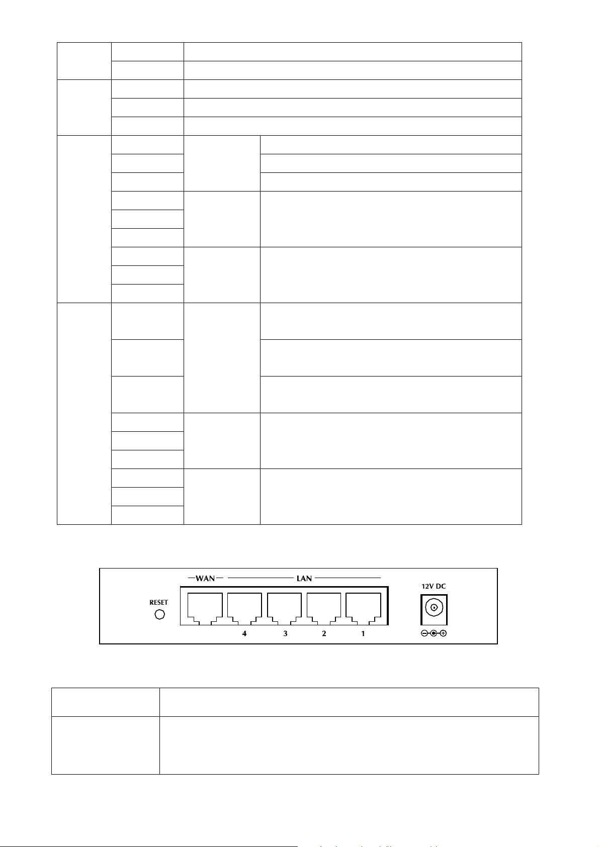
Rear Panel Port and Button Definition
Port Description
RESET
This button has two (2) functions:
Reboot When pressed and released, XRT-501 will reboot (restart).
Clear All Data Hold the button longer than 5 seconds then release,
8
Page 9
this can be clear ALL data and restore ALL settings to the factory
default values.
WAN
LAN (1-4)
12VDC
Connect your xDSL or Cable modem and is linked to the Internet.
Connect your LAN’s PCs, printer servers, hubs and switches etc.
DC Power in.
1.4 Requirements
DSL or Cable modem for broadband Internet access.
Network cables. Use standard 10/100/1000BaseT network (UTP) cables with RJ45
connectors.
TCP/IP network protocol installed on each PC.
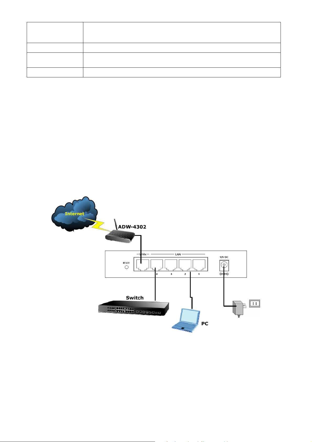
1.5 Physical Installation
Setup your network as shown in the setup diagram below
1. Use standard LAN cables to connect PCs to the Switching Hub ports on the XRT-501,
or you can directly connect PCs to XRT-501, you may use 10Base-T, 100Base-TX, or
1000Base-T connections, and all connection types can be used simultaneously.
2. If required, connect any port to a normal port on another Hub, using a standard LAN
cable. Any LAN port on the XRT-501 will automatically function as an "Uplink" port
when required.
9
Page 10

3. Connect the DSL or Cable modem to the WAN port on the XRT-501. Use the cable
supplied with your DSL/Cable modem. If no cable was supplied, use a standard cable.
4. Connect the supplied Power Adapter and power on.
5. Check the LEDs
The Power LED should be ON.
Status LED should flash, and then turn off. If it stays on, there is a hardware error.
For each LAN connection, one of the LAN LEDs (10, 100, or 1000) should be ON
(provided the PC is also ON.)
One of the WAN LEDs (10, 100, or 1000) should be ON, provided the Broadband
modem is powered up.
1.6 Configuration
Then, you need to setup your LAN PC clients, so that it can obtain an IP address
automatically. By default the XRT-501’s DHCP server is enabled, so you can obtain an IP
address automatically.
Please make sure that the XRT-501’s DHCP server is the only DHCP
Note
server available on your LAN. If there is another DHCP on your network,
then you’ll need to switch one of the DHCP servers off.
Step1 Configure your PC to obtain an IP address automatically
This section will show you how to configure your PC’s so that it can obtain an IP address
automatically for either Windows 98/Me, 2000 or later operating systems.
For other operating systems (Macintosh, Sun, etc.), please follow the manufacturer’s
instructions. The following is a step-by-step illustration on how to configure your PC to
obtain an IP address automatically for 2a) Windows XP, 2b) Windows 2000, and 2c)
Windows 98/Me
2a) Configuring PC in Windows XP
1. Go to Start / Control Panel (in Classic View). In the Control Panel, double-click on
Network Connections
2. Double-click Local Area Connection.
10
Page 11
3. In the Local Area Connection Status window, click Properties.
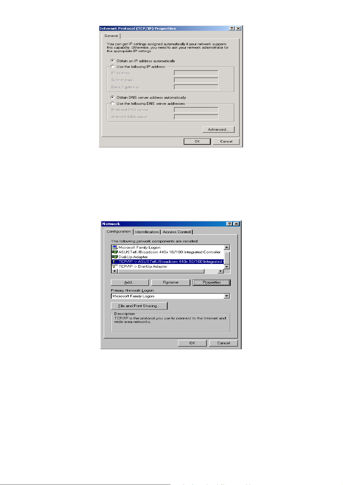
4. Select Internet Protocol (TCP/IP) and click Properties.
11
Page 12
5. Select the Obtain an IP address automatically and the Obtain DNS server address
automatically radio buttons.
6. Click OK to finish the configuration.
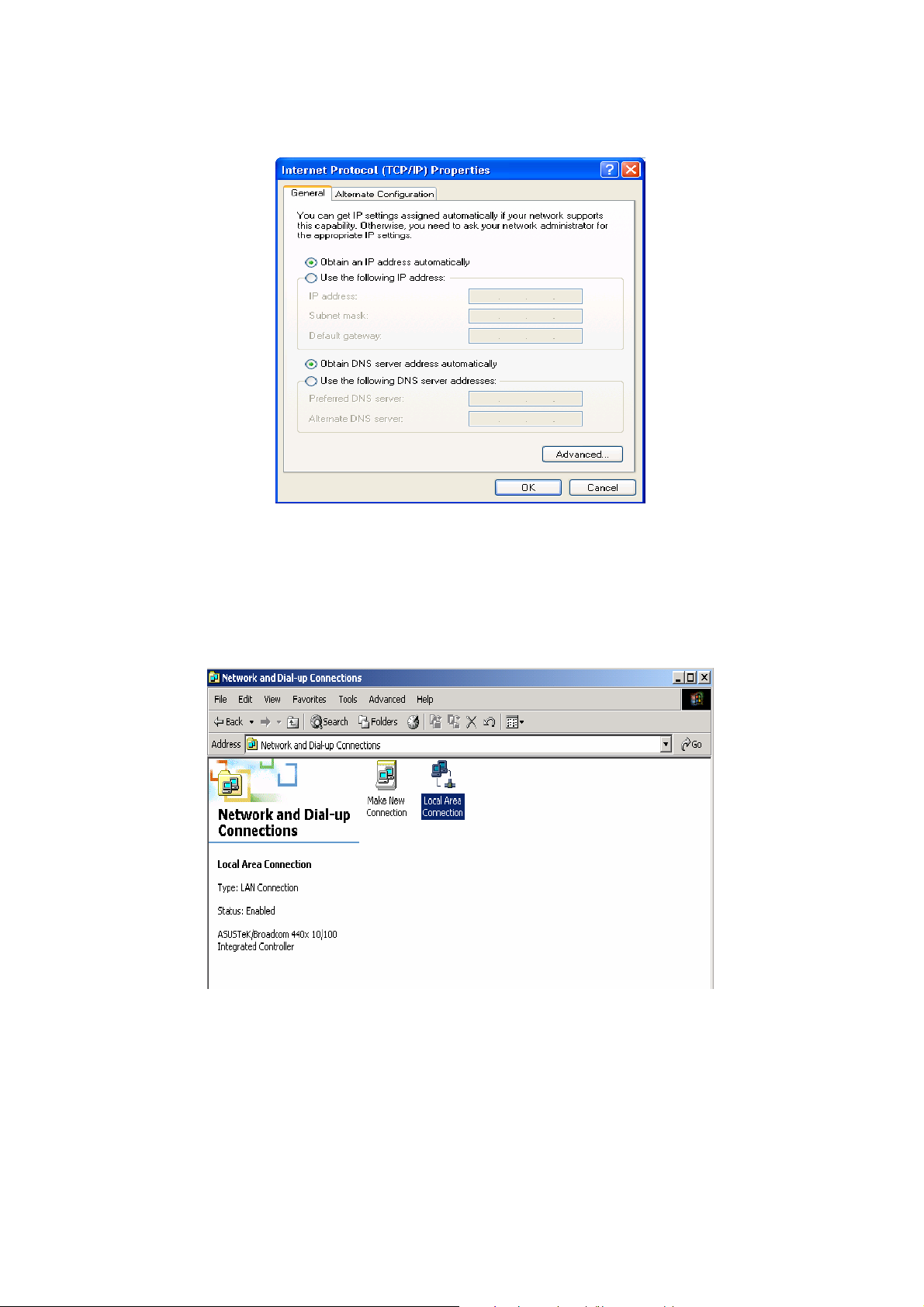
2b) Configuring PC in Windows 2000
1. Go to Start / Settings / Control Panel. In the Control Panel, double-click on Network
and Dial-up Connections.
2. Double-click Local Area Connection.
3. In the Local Area Connection Status window click Properties.
4. Select Internet Protocol (TCP/IP) and click Properties.
5. Select the Obtain an IP address automatically and the Obtain DNS server address
automatically radio buttons.
6. Click OK to finish the configuration.
12
Page 13
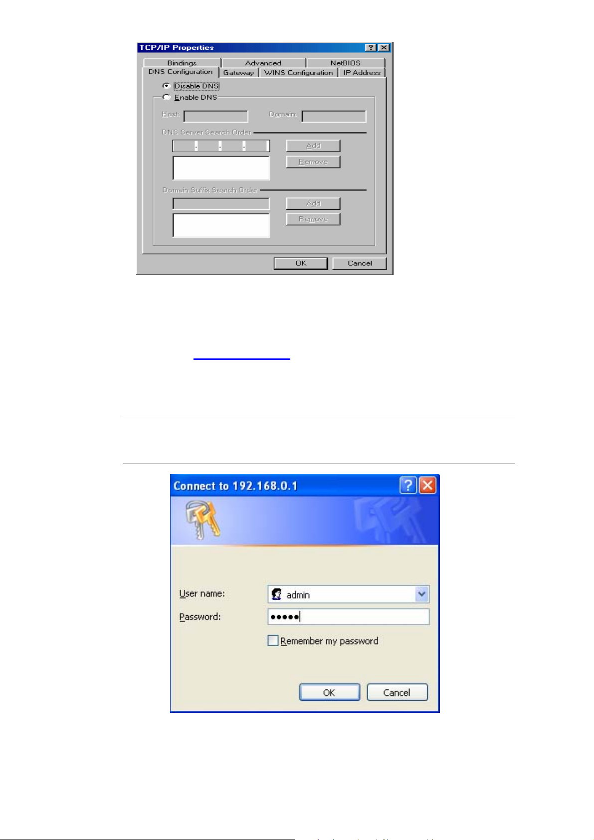
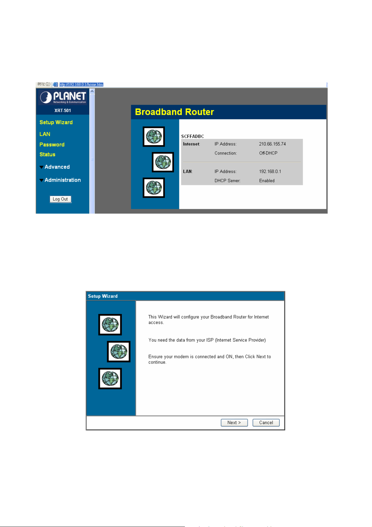
2c) Configuring PC in Windows 98/Me
1. Go to Start / Settings / Control Panel. In the Control Panel, double-click on Network
and choose the Configuration tab.
2. Select TCP/IP NE2000 Compatible, or the name of your Network Interface Card
(NIC) in your PC.
3. Select the Obtain an IP address automatically radio button.
4. Then select the DNS Configuration tab.
5. Select the Disable DNS radio button and click OK to finish the configuration.
13
Page 14
Step2 Configuring with Web Browser
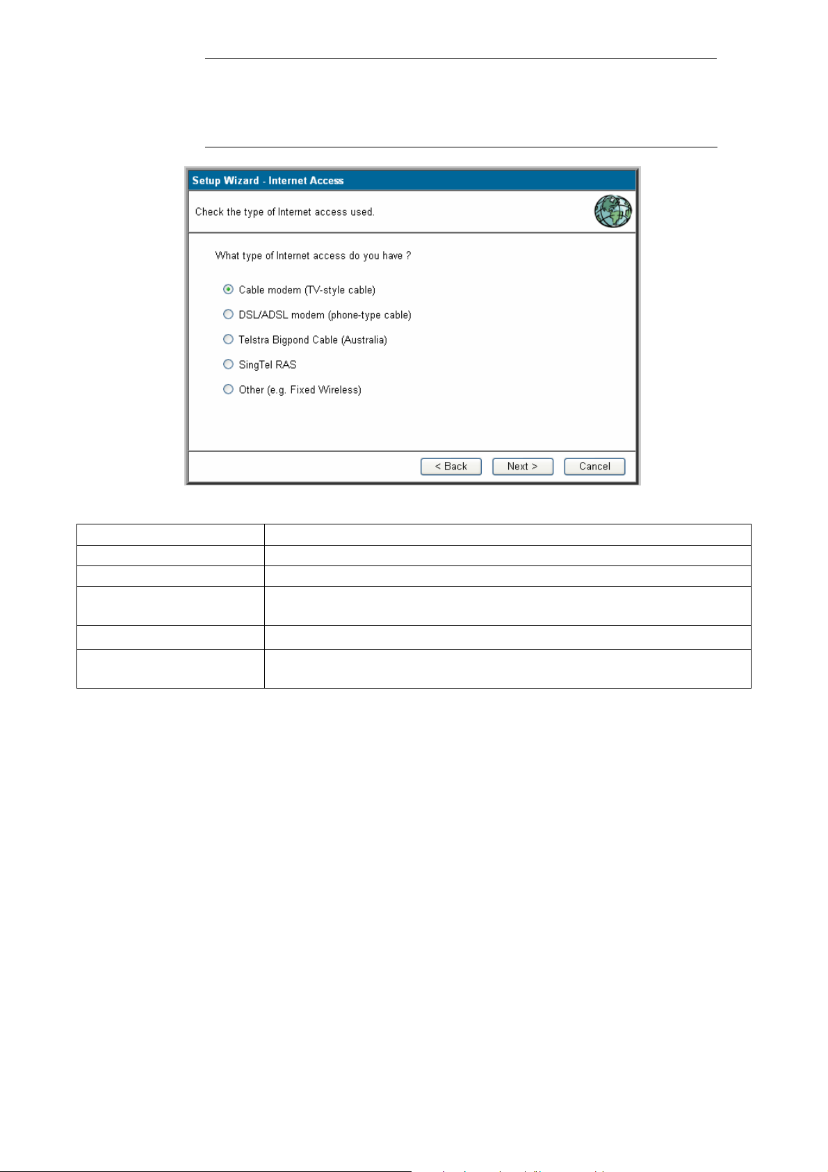
Once your PC has obtained an IP address from your router, please start your Web Browser.
In the Address box, enter http://192.168.0.1,and then press <enter>
The login screen below will appear. Enter the “User Name” and “Password” and then click
<OK> to login.
By default, the user name and password both are “admin”. For security
Note
reasons it is recommended to change the password at the first login and
memorize it.
14
Page 15
Chapter2 General Setup
2.1 Setup Wizard
The following picture is XRT-501’s home screen:
This section intends to help you setup the XRT-501 as fast as possible. The setup includes
Wizard setup, and different type of Internet connection. For more information about the
settings, please also refer to the user’s manual in the supplied CD-ROM.
In the Setup Wizard you are required to fill in only the information necessary to access the
Internet. Once you click on the Wizard, you will see the screen below.
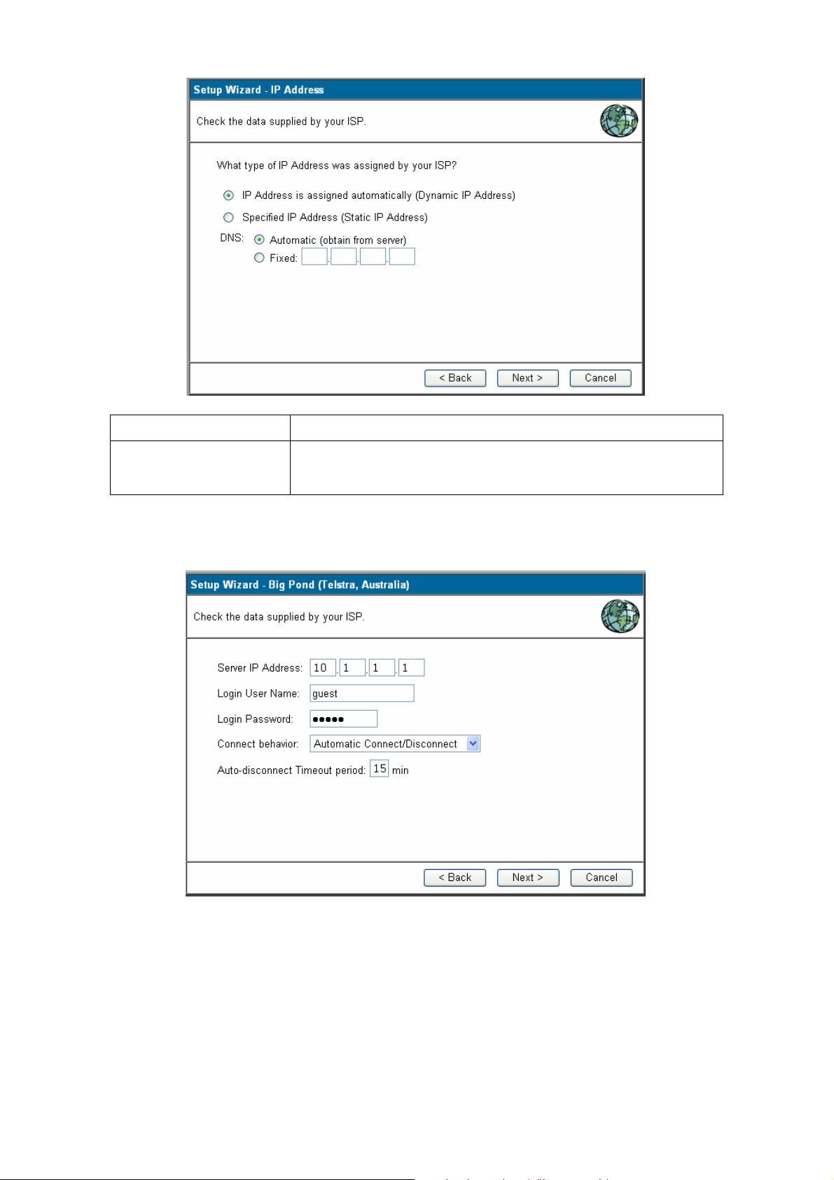
Step1) Choose your ISP type
In this section you have to select one of these types of connections that you will be using to
connect your XRT-501’s WAN port to your ISP (see screen below).
15
Page 16
Different ISP’s require different methods of connecting to the
Note
Internet, please check with your ISP as to the type of connection it
requires.
Parameter Description
2.1.1 Cable Modem
2.1.2 DSL/ADSL
2.1.3 Telstra Bigpond
Your ISP will automatically give you an IP address.
Your ISP has given you an IP address already
For Telstra BigPond (Australia) use only.
Cable
2.1.4 SingTel RAS
2.1.5 Other
For SingTel RAS (Singapore) use.
You can directly to setup the ISP type with Specified (Fixed) or
Dynamic IP Address
Click on one of the WAN types and then proceed to the manual’s relevant sub-section
(2.1.1, 2.1.2, 2.1.3, 2.1.4, or 2.1.5). Click on Back to return to the previous screen.
2.1.1 Cable mode(TV-Style cable)
Choose Cable Modem if you’re ISP will automatically give you an IP address. Some ISP’s
may also require that you fill in additional information such as MAC address (see screen
below).
16
Page 17
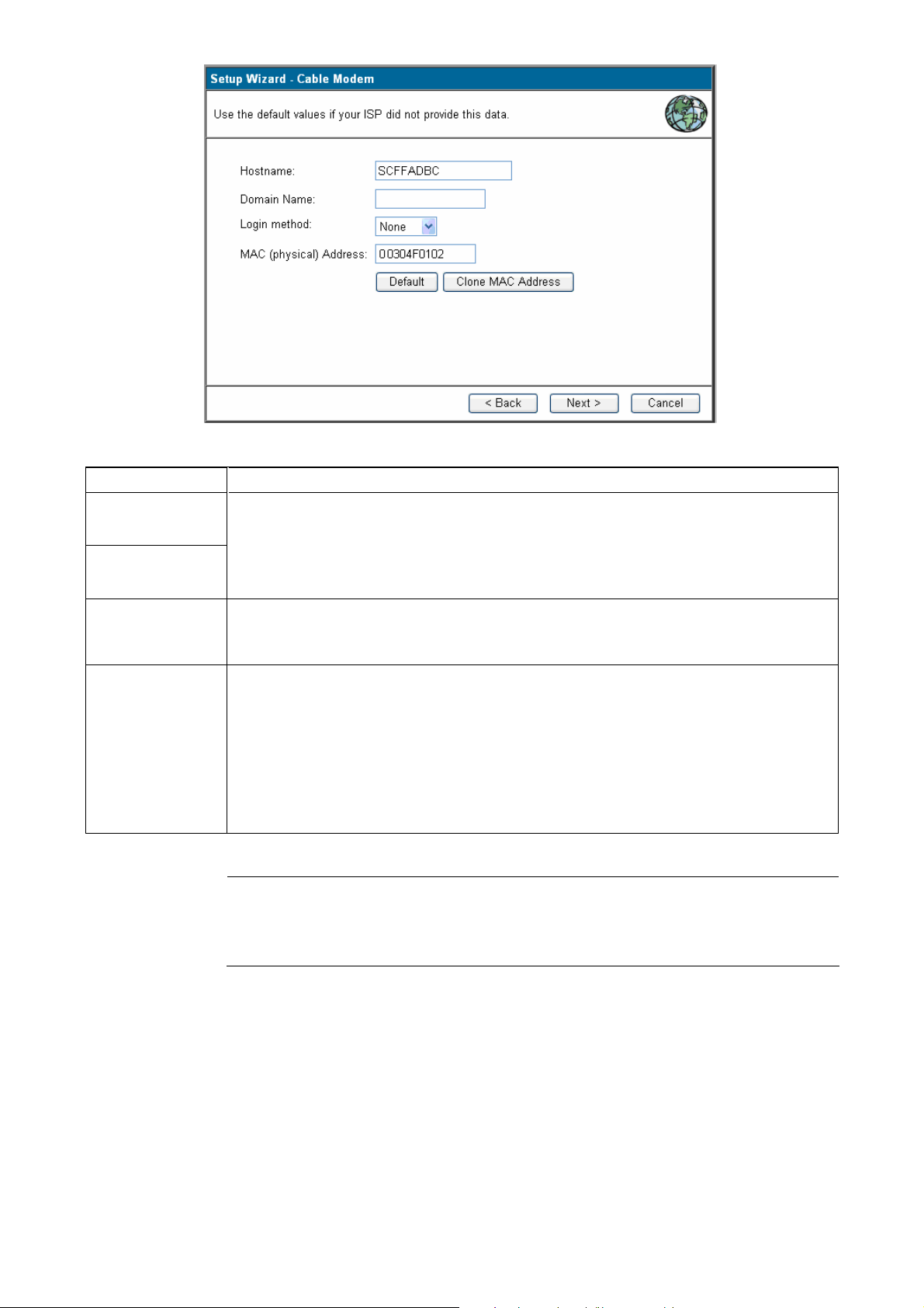
Parameter Description
Host Name
Some ISP's may also require you to use a particular Hostname, Domain
name, or MAC (physical) address. If required, please enter Hostname,
Domain Name
Domain name provided by your ISP.
Clone MAC
Address
MAC(physical)
Address
Use “Clone MAC address" button to copy the MAC (physical) address
from your PC to the XRT-501.
Your ISP may require a particular MAC address in order for you to connect
to the Internet. This MAC address is the PC’s MAC address that your ISP
had originally connected your Internet connection to. Type in this MAC
address in this section or use the Clone MAC Address button to replace
the WAN MAC address with the MAC address of that PC (you have to be
using that PC for the Clone MAC Address button to work).
Note
The MAC address section is optional and you can skip this section if your
ISP does not require these settings for you to connect to the Internet.
2.1.2 DSL/ADSL modem(phone-type cable)
In this section you have to select one of these DSL/ADSL types that you will be using to
connect your XRT-501’s WAN port to your ISP (see screen below).
17
Page 18
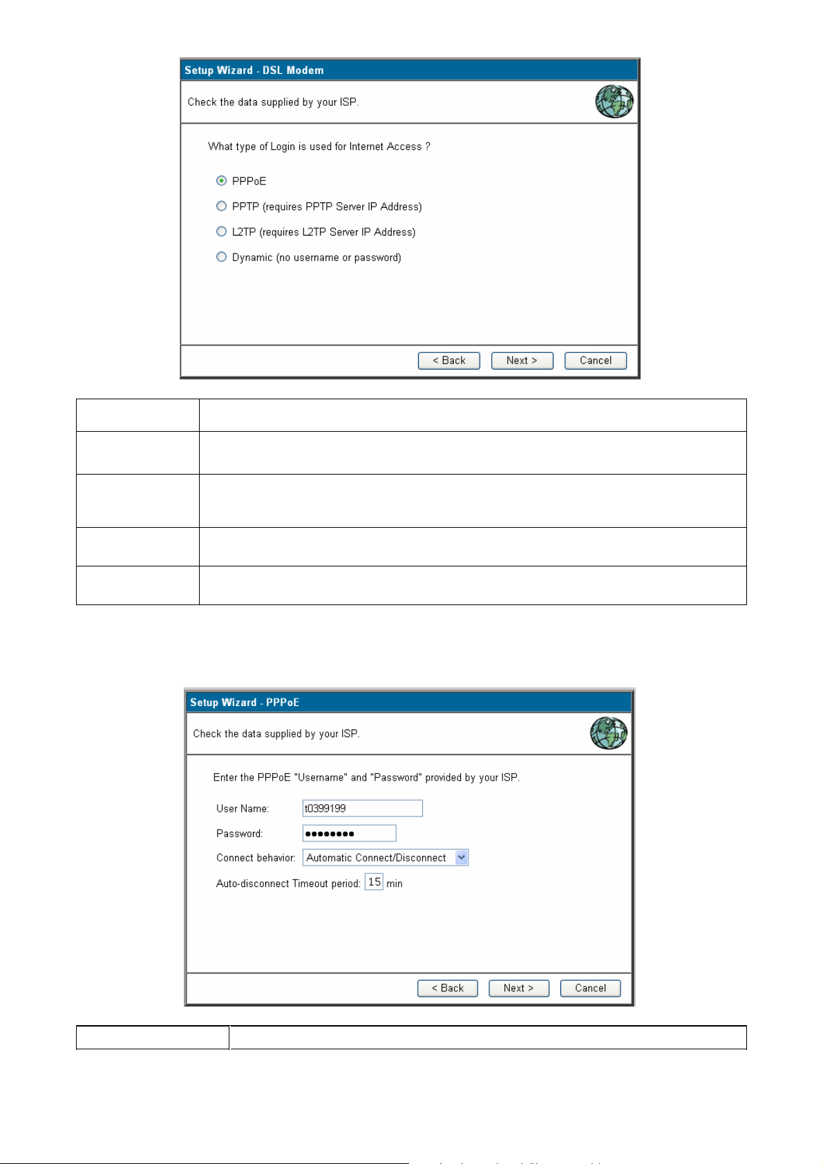
Parameter Description
2.1.2.1 PPPoE
Your ISP requires you to use a Point-to-Point Protocol over Ethernet
(PPPoE) connection.
2.1.2.2 PPTP
Your ISP requires you to use a Point-to-Point Tunneling Protocol (PPTP)
connection.
2.1.2.3 L2TP
Layer 2 Tunneling Protocol is a common connection method used in xDSL
connections.
2.1.2.4
Your ISP will automatically give you an IP address.
Dynamic
2.1.2.1 PPPoE
Select Dial-Up xDSL (PPPoE) if you’re ISP requires the PPPoE protocol to connect you to
the Internet. Your ISP should provide all the information required in this section.
Parameter Description
18
Page 19
User Name Enter the User Name provided by your ISP for the PPPoE connection.
Password Enter the Password provided by your ISP for the PPPoE connection.
Connect behavior Select the connection behaviors that you wish it be to Automatic
Connect, Manual Connect, or Keep alive.
Auto-disconnect
Timeout period
You can specify an idle time threshold (minutes) for the WAN port.
This means if no packets have been sent (no one using the Internet)
during this specified period, the router will automatically disconnect
the connection with your ISP.
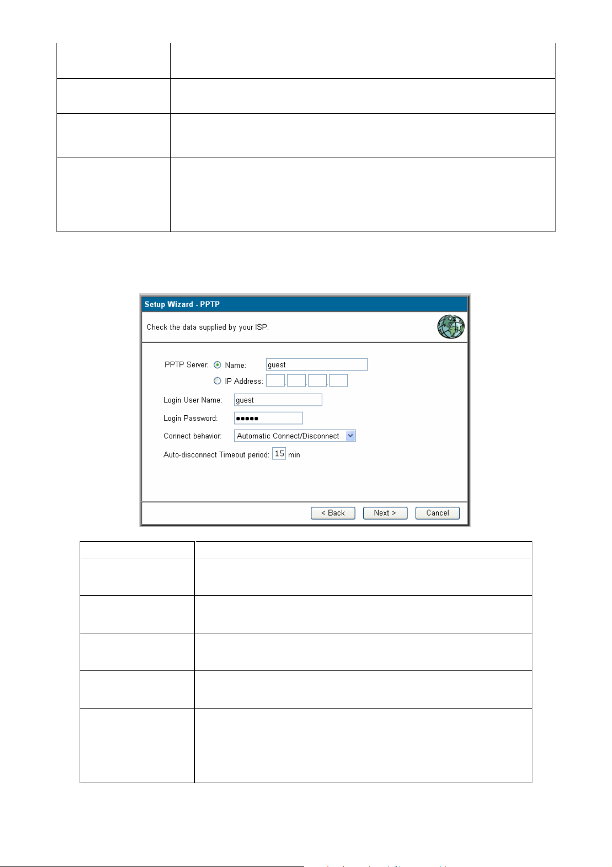
2.1.2.2 PPTP
Select PPTP if your ISP requires the PPTP protocol to connect you to the Internet. Your
ISP should provide all the information required in this section.
Parameter Description
PPTP Server Specify PPTP Server Name or IP address that you want to
connect to.
Login User Name Enter the User Name provided by your ISP for the PPTP
connection.
Login Password Enter the Password provided by your ISP for the PPTP
connection.
Connect behavior Select the connection behaviors that you wish it be to
Automatic Connect, Manual Connect, or Keep alive.
Auto-disconnect
Timeout period
You can specify an idle time threshold (minutes) for the WAN
port. This means if no packets have been sent (no one using
the Internet) during this specified period, the router will
automatically disconnect the connection with your ISP.
19
Page 20
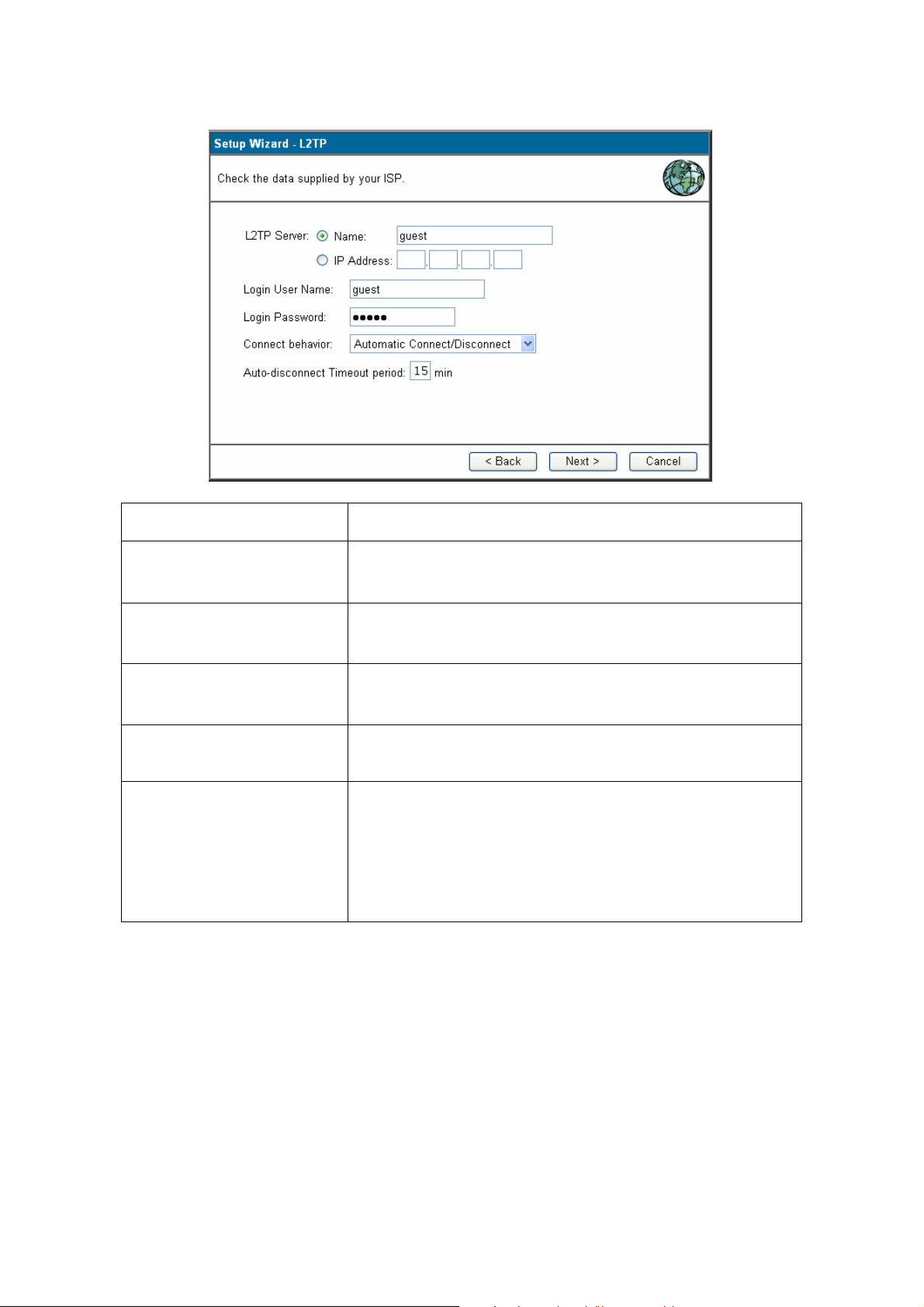
2.1.2.3 L2TP
Select L2TP if your ISP requires the L2TP protocol to connect you to the Internet. Your ISP
should provide all the information required in this section.
Parameter Description
L2TP Sever Specify L2TP Server Name or IP address that you
want to connect to.
Login User Name Enter the User Name provided by your ISP for the
L2TP connection.
Login Password Enter the Password provided by your ISP for the L2TP
connection.
Connect behavior Select the connection behaviors that you wish it be to
Automatic Connect, Manual Connect, or Keep alive.
Auto-disconnect Timeout
period
You can specify an idle time threshold (seconds) for
the WAN port. This means if no packets have been
sent (no one using the Internet) during this specified
period, the router will automatically disconnect the
connection with your ISP.
20
Page 21
2.1.2.4 Dynamic (no user name and password)
Parameter Description
Dynamic IP Address Your IP Address is allocated automatically, when you
connect to you ISP.
2.1.3 Telstra Bigpond Cable (Australia)
This connection is only for Telstra BigPond (Australia) use.
For this connection method, the following data is required, and these information provided
by your ISP.
User Name
Password
Big Pond Server IP address
21
Page 22
2.1.4 SingTel RAS
This connection is only for SingTel RAS (Singapore) use.
For this connection method, the following data is required, and these information provided
by your ISP.
User Name
Password
RAS Plan
2.1.5 Other
Specified (Fixed)
IP Address
Parameter Description
The IP Address provided by your ISP, and related
information.
22
Page 23
Dynamic IP Address Your IP Address is allocated automatically, when you
connect to you ISP.
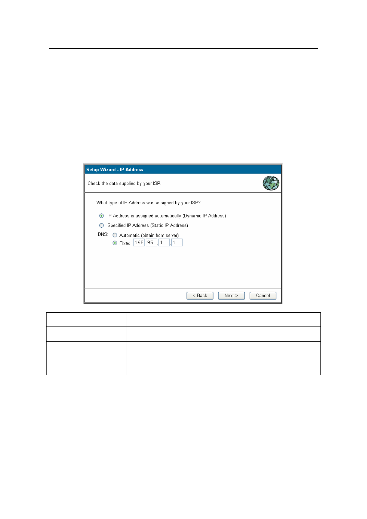
Step2) DNS
A Domain Name System (DNS) server is like an index of IP addresses and W eb addresses.
If you type a Web address into your browser, such as www.router.com, a DNS server will
find that name in its index and the matching IP address. Most ISPs provide a DNS server
for speed and convenience. If your Service Provider connects you to the Internet with
dynamic IP settings, it is likely that the DNS server IP address is provided automatically.
However, if there is a DNS server that you would rather use, you need to specify the IP
address of that DNS server here.
Parameter Description
Automatic It will detect the DNS server automatically
Fixed This is the ISP’s DNS server IP address that they gave
you; or you can specify your own preferred DNS server IP
address
Step3) Test Internet Connection
23
Page 24
Select “Test Internet Connection”, and then click <Finish> when you have finished the
configuration above. It will run the test and check the Internet connection can be
established or not.
Congratulations! You have completed the connection configuration after test successful,
and now you can start using the router.
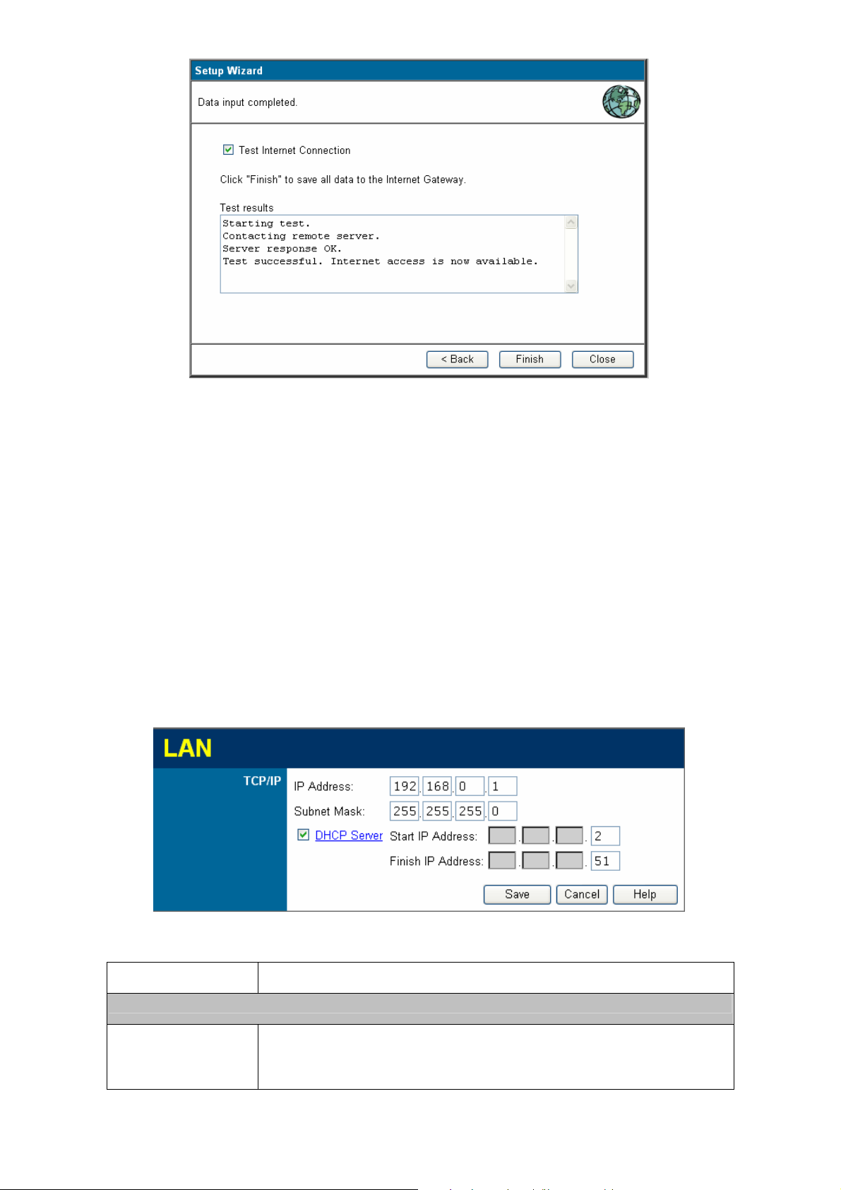
2.2 LAN
Use the LAN link on the main menu to reach the LAN screen. An example screen is shown
below.
You can specify the LAN segment’s IP address, subnet Mask,enable/disable DHCP and
select an IP range for your LAN, you also can check DHCP client list in here.
TCP/IP
IP Address
Parameter Description
This is the XRT-501’s LAN port IP address, and your
LAN clients default gateway IP address. (For XRT-501’s default
LAN IP address is 192.168.0.1)
24
Page 25

Subnet Mask
The default value 255.255.255.0 is standard for small (class
"C") networks. For other networks, use the Subnet Mask for the
LAN segment to which the XRT-501 is attached (the same
value as the PCs on that LAN segment).
DHCP Server If Enabled, the XRT-501 will allocate IP Addresses to PCs
(DHCP clients) on your LAN automatically when they start
up.The default (and recommended) value is Enabled.
If you are already using a DHCP Server, this setting must
be Disabled, and the existing DHCP server must be
re-configured to treat the XRT-501 as the default Gateway.
See thefollowing section for further details.
The Start IP Address and Finish IP Address fields set the
values used by the DHCP server when allocating IP Addresses
to DHCP clients. This range also determines the number of
DHCP clients supported.See the following section for further
details on using DHCP.
Buttons
Save Save the data on screen.
Cancel The "Cancel" button will discard any data you have
entered and reload the file from the XRT-501.
What DHCP Does
A DHCP (Dynamic Host Configuration Protocol) Server allocates a valid IP address to a
DHCP Client (PC or device) upon request.
The client request is made when the client device starts up (boots).
The DHCP Server provides the Gateway and DNS addresses to the client, as well as
allocating an IP Address.
The XRT-501 can act as a DHCP server.
Windows 95/98/ME and other non-Server versions of Windows will act as a DHCP
client. This is the default Windows setting for the TCP/IP network protocol. However,
Windows uses the term Obtain an IP Address automatically instead of "DHCP
Client".
You must NOT have two or more DHCP Servers on the same LAN segment. (If
your LAN does not have other Routers, this means there must only be one DHCP
Server on your LAN.)
25
Page 26
Using the XRT-501's DHCP Ser ver
This is the default setting. The DHCP Server settings are on the LAN screen. On this
screen, you can:
Enable or Disable the XRT-501's DHCP Server function.
Set the range of IP Addresses allocated to PCs by the DHCP Server function.
You can assign Fixed IP Addresses to some devices while using DHCP,
Note
provided that the Fixed IP Addresses are NOT within the range used by the
DHCP Server.
Using another DHCP Server
You can only use one DHCP Server per LAN segment. If you wish to use another DHCP
Server, rather than the XRT-501's, the following procedure is required.
Disable the DHCP Server feature in the XRT-501. This setting is on the LAN
screen.
Configure the DHCP Server to provide the XRT-501's IP Address as the
Default Gateway.
To Configure your PCs to use DHCP
This is the default setting for TCP/IP under Windows 98/Me, 2000 or later operating
systems.See 1.6 Configuration for the procedure to check these settings.
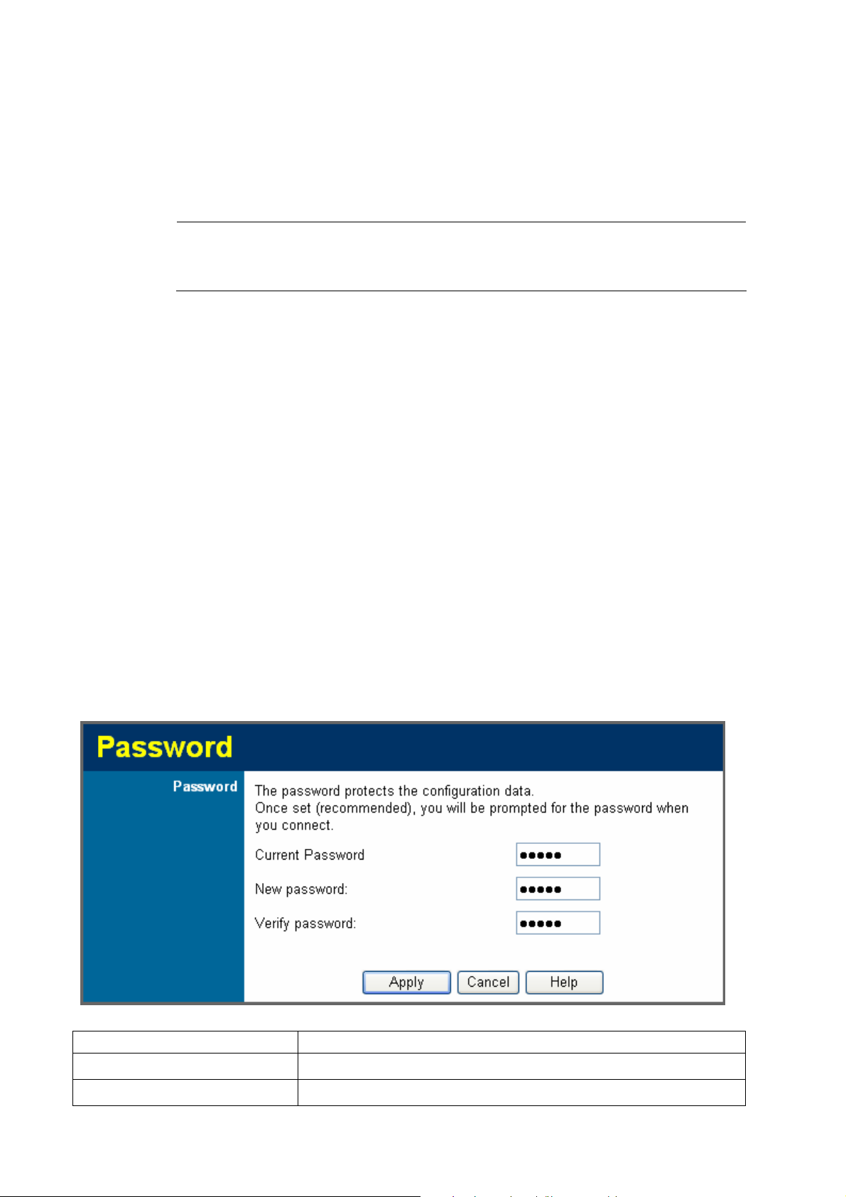
2.3 Password
The Password settings function allows you to design password to the XRT-501.
Parameter Description
Current assword
Password
Enter the current password for verification.
Type a new password in order to access the Web-Based
26
Page 27
Verify Password
2.4 St atus
management website.
Re-Type the password for confirmation.
Use the Status link on the main menu to check XRT-501 system status and concurrent
hardware information.
27
Page 28

Parameter Description
Internet
Connection Method
Broadband Modem
Internet Connection
Internet IP Address
WAN MTU
LAN
IP Address
Network Mask
DHCP Server
This indicates the current connection method, as set in
the Setup Wizard.
This shows the connection status of the modem.
Current connection status: Active,Idle,Unknown, and
Failed. If there is an error, you can click the "Connection
Details" button to find out more information.
This IP Address is allocated by the ISP (Internet Service
Provider).
Displays the current value of MTU.
The IP Address of the XRT-501.
The Network Mask (Subnet Mask) for the IP Address
above.
This shows the status of the DHCP Server function either "Enabled" or "Disabled".
System
Device Name
Firmware Version
Buttons
"Connection Details"
Button
System Data
System Data
Restart
For additional information about the PCs on your LAN,
and the IP addresses allocated to them, use the PC
Database option on the Advanced menu.
This displays the current name of the XRT-501.
The current version of the firmware installed in the
XRT-501.
Click this button to open a Sub-Window and view a
detailed description of the current connection.
Depending on the type of connection, a "log" may also
be available.
Display all system information in a sub-window.
Display all system log in a sub-window.
Clicking this button will restart (reboot) the XRT-501. All
Refresh Screen
existing connections though the XRT- 501 will be
terminated, but will usually re-connect automatically.
Update the data displayed on screen.
28
Page 29

Connection Details - Fixed/Dynamic IP Address
If your access method is "Direct" (no login), a screen like the following example will be
displayed when the "Connection Details" button is clicked.
Parameter Description
Internet
Physical Address
IP Address
Network Mask
Default Gateway
DNS IP Address
The hardware address of this device, as seen by remote
devices on the Internet.(This is different as the hardware
address by the devices on the local LAN.)
The IP Address of this device, as seen by Internet users.
This address is allocated by your ISP (Internet Service
Provider).
The Network Mask associated with the IP Address
above.
The IP Address of the remote Gateway or Router
associated with the IP Address above.
The IP Address of the Domain Name Server which is
DHCP Client
currently used.
This will show "Enabled" or "Disabled", depending on
whether or not this device is functioning as a DHCP
client.
If "Enabled", the "Remaining lease time" field indicates
when the IP Address allocated by the DHCP Server will
expire. The lease is automatically renewed on expiry;
29
Page 30

Buttons
use the "Renew" button if you wish to manually renew
the lease immediately.
Release/Renew Button
will display EITHER
"Release" OR "Renew"
Refresh
This button is only useful if the IP address shown above
is allocated automatically on connection. (Dynamic IP
address). If you have a Fixed (Static) IP address, this
button has no effect.
If the ISP's DHCP Server has NOT allocated an IP
Address for the XRT-501, this button will say
"Renew". Clicking the "Renew" button will attempt to
re-establish the connection and obtain an IP Address
from the ISP's DHCP Server.
If an IP Address has been allocated to XRT-501
(by the ISP's DHCP Server), this button will say
"Release". Clicking the "Release" button will break
the connection and release the IP Address.
Update the data shown on screen.
Connection Status - PPPoE
If using PPPoE (PPP over Ethernet), a screen like the following example will be displayed
when the "Connection Details" button is clicked.
30
Page 31

Internet
Parameter Description
Physical Address
IP Address
Network Mask
PPPoE Link Status
Connection Log
Connection Log
The hardware address of this device, as seen by remote
devices on the Internet. ((This is different as the
hardware address by the devices on the local LAN.)
The IP Address of this device, as seen by Internet users.
This address is allocated by your ISP (Internet Service
Provider).
The Network Mask associated with the IP Address
above.
This indicates whether or not the connection is currently
established.
If the connection does not exist, the "Connect" button
can be used to establish a connection.
If the connection currently exists, the "Disconnect"
button can be used to break the connection.
The Connection Log shows status messages relating to
Buttons
Connect
Disconnect
Clear Log
Refresh
Connection Log Messages
Parameter Description
the existing connection.
The most common messages are listed in the table
below.
The "Clear Log" button will restart the Log, while the
Refresh button will update the messages shown on
screen.
If not connected, establish a connection to your ISP.
If connected to your ISP, hang up the connection.
Delete all data currently in the Log. This will make it
easier to read new messages.
Update the data on screen.
Connection Log Messages
31
Page 32

Connect on Demand Connection attempt has been triggered by the "Connect
automatically, as required" setting.
Manual connection Connection attempt started by the "Connect" button.
Reset physical connection Preparing line for connection attempt.
Connecting to remote
Attempting to connect to the ISP's server.
server
Remote Server located ISP's Server has responded to connection attempt.
Start PPP Attempting to login to ISP's Server and establish a PPP
connection.
PPP up successfully Able to login to ISP's Server and establish a PPP
connection.
Idle time-out reached The connection has been idle for the time period
specified in the "Idle Time-out" field. The connection will
now be terminated.
Disconnecting The current connection is being terminated, due to
either the "Idle Time-out" above, or "Disconnect" button
being clicked.
Error: Remote Server not
found
Error: PPP Connection
ISP's Server did not respond. This could be a Server
problem, or a problem with the link to the Server.
Unable to establish a PPP connection with the ISP's
failed
Server. This could be a login problem (name or
password) or a Server problem.
Error: Connection to
Server lost
The existing connection has been lost. This could be
caused by a power failure, a link failure, or Server
failure.
Error: Invalid or unknown
packet type
The data received from the ISP's Server could not be
processed. This could be caused by data corruption
(from a bad link), or the Server using a protocol which is
not supported by this device.
Connection Status - PPTP
If using PPTP (Peer-to-Peer Tunneling Protocol), a screen like the following example will
be displayed when the "Connection Details" button is clicked.
32
Page 33

Connection
Parameter Description
Physical Address
IP Address
PPTP Status
Connection Log
Connection Log
The hardware address of this device, as seen by remote
devices on the Internet. (This is different as the
hardware address by the devices on the local LAN.)
The IP Address of this device, as seen by Internet users.
This address is allocated by your ISP (Internet Service
Provider).
This indicates whether or not the connection is currently
established.
If the connection does not exist, the "Connect" button
can be used to establish a connection.
If the connection currently exists, the "Disconnect"
button can be used to break the connection.
The Connection Log shows status messages relating to
the existing connection.The "Clear Log" button will
Buttons
Connect
restart the Log, while the Refresh button will update the
messages shown on screen.
If not connected, establish a connection to your ISP.
33
Page 34

Disconnect
If connected to your ISP, hang up the connection.
Clear Log
Delete all data currently in the Log. This will make it
easier to read new messages.
Refresh
Update the data on screen.
Connection Status - L2TP
If using L2TP, a screen like the following example will be displayed when the "Connection
Details" button is clicked.
Parameter Description
Connection
Physical Address
IP Address
Connection Status
The hardware address of this device, as seen by remote
devices on the Internet. (This is different as the
hardware address by the devices on the local LAN.)
The IP Address of this device, as seen by Internet users.
This address is allocated by your ISP (Internet Service
Provider).
This indicates whether or not the connection is currently
established.
If the connection does not exist, the "Connect" button
can be used to establish a connection.
If the connection currently exists, the "Disconnect"
button can be used to break the connection.
34
Page 35

Connection Log
Connection Log
The Connection Log shows status messages relating to
the existing connection.
The "Clear Log" button will restart the Log, while the
Refresh button will update the messages shown on
screen.
Buttons
Connect
Disconnect
Clear Log
If not connected, establish a connection to your ISP.
If connected to your ISP, hang up the connection.
Delete all data currently in the Log. This will make it
easier to read new messages.
Refresh
Update the data on screen.
Connection Status - Telstra Big Pond
An example screen is shown below.
Parameter Description
Connection
Physical Address
IP Address
The hardware address of this device, as seen by remote
devices. (This is different as the hardware address by
the devices on the local LAN.)
The IP Address of this device, as seen by Internet users.
35
Page 36

This address is allocated by your ISP (Internet Service
Provider).
Connection Status
Connection Log
Connection Log
Buttons
Connect
This indicates whether or not the connection is currently
established.
If the connection does not exist, the "Connect"
button can be used to establish a connection.
If the connection currently exists, the "Disconnect"
button can be used to break the connection.
Normally, it is not necessary to use the Connect and
Disconnect buttons unless the setting "Connect
automatically, as required" is disabled.
The Connection Log shows status messages relating to
the existing connection.
If not connected, establish a connection to Telstra Big
Pond.
Disconnect
If connected to Telstra Big Pond, terminate the
connection.
Clear Log
Delete all data currently in the Log. This will make it
easier to read new messages.
Refresh
Update the data on screen.
Connection Details - SingTel RAS
If using the SingTel RAS access method, a screen like the following example will be
displayed when the "Connection Details" button is clicked.
36
Page 37

Parameter Description
Internet
RAS Plan
Physical Address
IP Address
Network Mask
Default Gateway
DNS IP Address
DHCP Client
The RAS Plan which is currently used.
The hardware address of this device, as seen by remote
devices on the Internet. (This is different as the
hardware address by the devices on the local LAN.)
The IP Address of this device, as seen by Internet users.
This address is allocated by your ISP (Internet Service
Provider).
The Network Mask associated with the IP Address
above.
The IP Address of the remote Gateway or Router
associated with the IP Address above.
The IP Address of the Domain Name Server which is
currently used.
This will show "Enabled" or "Disabled", depending on
whether or not this device is functioning as a DHCP
client.
Buttons
Release/Renew Button
will display EITHER
"Release" OR "Renew"
If "Enabled" the "Remaining lease time" field
indicates when the IP Address allocated by the
DHCP Server will expire. The lease is automatically
renewed on expiry; use the "Renew" button if you
wish to manually renew the lease immediately.
This button is only useful if the IP address shown above
is allocated automatically on connection. (Dynamic IP
address). If you have a Fixed (Static) IP address, this
button has no effect.
If the ISP's DHCP Server has NOT allocated an IP
Address for the XRT-501, this button will say
"Renew". Clicking the "Renew" button will attempt to
re-establish the connection and obtain an IP Address
from the ISP's DHCP Server.
If an IP Address has been allocated to the XRT-501
(by the ISP's DHCP Server), this button will say
"Release". Clicking the "Release" button will break
the connection and release the IP Address.
37
Page 38

Refresh
Update the data shown on screen.
Chapter3 Advance Features
If you have already configured the Wizard, you do NOT need to configure anything for you
to start using the Internet.
Advance features that allow you to configure the router to meet your network’s needs such
as: Special Applications, DMZ, Virtual Servers, Qos, and Firewall options…etc.
Below is a general description of what advance functions are available for the XRT-501.
Parameter Description
3.1 Access Control
3.2 Dynamic DNS
3.3 Internet
3.4 URL Filiter
3.5 Schedule
3.6 User Groups
3.7 Virtual Servers
To restrict the level of Internet Access available to PCs on your
LAN
You can configure DDNS service in this section.
This section allows you to configure the Communication
Applications, Special Applications, DMZ, and Mulit-DMZ
functions relating to Internet access.
This section allow you to restrict access to some Web sites
from particular PCs by entering a full URL address or just
keyword of the Web site.
Two separate sessions or periods can be defined.
This section allow you to configure PCs to different group and
using the specify service.
You can configure the Virtual Server in this section. This
38
Page 39

allows you to specify what user/packet can pass your router’s
NAT.
3.8 QoS
3.9 Streaming
Accelerator
3.10 IGMP
3.11 Packet Capture
3.12 WAN Port
Select one of the above advance features selections and proceed to the manual’s relevant
subsection.
You can configure the QoS control by four level.
Thist will get accelerate via enable this function.
IGMP (Internet Group Multicast Protocol): It is a session-layer
protocol used to establish membership in a multicast group.
It provides the feauture can monitor the LAN or WAN traffic.
This section allows you to select the connection method in
order to establish a connection with your ISP (same as the
Wizard section)
3.1 Access Control
The Access Control feature allows administrators to restrict the level of Internet Access
available to PCs on your LAN. With the default settings, everyone has unrestricted Internet
access.
To use this feature:
Set the desired restrictions on the "Default" group. All PCs are in the "Default" group
unless explicitly moved to another group.
Set the desired restrictions on the other groups ("Group 1", "Group 2", "Group 3" and
"Group 4") as needed.
Assign PC to the groups as required.
Restrictions are imposed by blocking "Services", or types of connections.
Note
All common Services are Pre-Defined.If required, you can also define your
own Services.
39
Page 40

Parameter Description
Group
Group
Internet Access
Restrictions
Block by Schedule
Select the desired Group. The screen will update to
display the settings for the selected Group. Groups are
named "Default", "Group 1", "Group 2", "Group 3" and
"Group 4", and cannot be re-named.
Select the desired options for the current group:
None:Nothing is blocked. Use this to create the least
restrictive group.
Block all Internet access: All traffic via the WAN
port is blocked. Use this to create the most restrictive
group.
Block selected Services: You can select which
Services are to block. Use this to gain fine control
over the Internet access for a group.
If Internet access is being blocked, you can choose
to apply the blocking only during scheduled times.
Services
If access is not blocked, no Scheduling is possible,
and this setting has no effect.
You can define or modify the Schedule using the
Schedule option on the Advanced menu.
This lists all defined Services. Select the Services you
40
Page 41

wish to block. To select multiple services, hold the CTRL
key while selecting. (On the Macintosh, hold the SHIFT
key rather than CTRL.)
Edit Service List Button
Buttons
Edit Service List
Save
Cancel
View Log
Clear Log
If you wish to define additional Services, or manage the
Service list, click this button to open the "Services"
screen.
If you wish to define additional Services, or manage the
Service list, click this button to open the "Services"
screen.
Save the data on screen.
Reverse any changes made since the last "Save".
Click this to open a sub-window where you can view the
"Access Control" log. This log shows attempted Internet
accesses which have been blocked by the Access
Control feature.
Click this to clear and restart the "Access Control" log,
making new entries easier to read.
Refresh
Update the data on screen.
3.1.1 Services
This screen is displayed when the Edit Service List button on the Access Control screen is
clicked.
41
Page 42

Parameter Description
Available Services
Available Services
"Delete" button
Add New Service
Name
Type
Start P ort
Finish Port
ICMP Type
This lists all the available services.
Use this to delete any Service you have added.
Pre-defined Services can not be deleted.
Enter a descriptive name to identify this service.
Select the protocol (TCP, UDP, ICMP) used to the
remote system or service.
For TCP and UDP Services, enter the beginning of the
range of port numbers used by the service. If the service
uses a single port number, enter it in both the "Start" and
"Finish" fields.
For TCP and UDP Services, enter the end of the range
of port numbers used by the service. If the service uses
a single port number, enter it in both the "Start" and
"Finish" fields.
For ICMP Services, enter the type number of the
Buttons
required service.
42
Page 43

Delete
A
Delete the selected service from the list.
Add
dd a new entry to the Service list, using the data shown
in the "Add New Service" area on screen.
Cancel
Clear the " Add New Service " area, ready for entering
data for a new Service.
3.1.2 Access Control Log
To check the operation of the Access Control feature, an Access Control Log is provided.
Click the View Log button on the Access Control screen to view this log.
This log shows attempted Internet accesses which have been blocked by the Access
Control function.
Parameter Description
Date/Time
Name
Source IP address
Date and Time of the attempted access.
If known, the name of the PC whose access was blocked.
The IP Address of the PC or device whose access request
was blocked
MAC address
The hardware or physical address of the PC or device whose
access request was blocked
Destination
Port
The destination URL or IP address
It shows the port number.
3.2 DDNS(Dynamic DNS)
Dynamic DNS (Domain Name Server)
This free service is very useful when combined with the Virtual Server feature. It allows
Internet users to connect to your Virtual Servers using a URL, rather than an IP Address.
This also solves the problem of having a dynamic IP address. With a dynamic IP address,
your IP address may change whenever you connect, which makes it difficult to connect to
you.
The Service works as follows:
You must register for the service at one of the listed DDNS Service Providers.
After registration, follow the service provider's procedure to request a Domain Name
and have it allocated to you.
Enter your DDNS data on the XRT-501's DDNS screen.
The XRT-501 will then automatically ensure that your current IP Address is
recorded at the DDNS server.
If the DDNS Service provides software to perform this "IP address update"; you
43
Page 44

should disable the "Update" function, or not use the software at all.
From the Internet, users will be able to connect to your Virtual Servers (or DMZ PC)
using your Domain Name.
Select Advanced on the main menu, then Dynamic DNS, to see a screen like the following:
Parameter Description
DDNS Service
DDNS Service
Web Site Button
DDNS Status
DDNS Data
User Name
Select the desired DDNS Service provider.
Click this button to open a new window and connect to
the Web site for the selected DDNS service provider.
This message is returned by the DDNS Server.
Normally, this message should be something like
"Update successful" (current IP address was updated on
the DDNS server).
If the message is "No host", this indicates the host
name entered was not allocated to you.
If you see some other error message, you need to
contact the DDNS Service and correct the problem.
Enter your Username for the DDNS Service.
Password/Key
Domain Name
Buttons
Enter your current password for the DDNS Service.
Enter the domain name allocated to you by the DDNS
Service. If you have more than one name, enter the
name you wish to use.
44
Page 45

Save
Save the data on screen.
Cancel
Reverse any changes made since the last "Save".
3.3 Advanced Internet
This section allows configuration of all advanced features relating to Internet access.
Communication Applications
Special Applications
DMZ
Multi-DMZ
An example screen is shown below.
3.3.1 Communication Applications
Most applications are supported transparently by the XRT-501. But sometimes it is not
clear which PC should receive an incoming connection. This problem could arise with the
Communication Applications listed on this screen.
If this problem arises, you can use this screen to set which PC should receive an incoming
connection, as described below.
Parameter Description
45
Page 46

Communication Applications
Select an Application
This lists applications which may generate incoming
connections, where the destination PC (on your local
LAN) is unknown.
Send incoming calls to
This lists the PCs on your LAN.If necessary, you can
add PCs manually, using the "PC Database" option on
the advanced menu.
For each application listed above, you can choose a
destination PC.There is no need to "Save" after each
change; you can set the destination PC for each
application, then click "Save".
3.3.2 Special Applications
If you use Internet applications which use non-standard connections or port numbers, you
may find that they do not function correctly because they are blocked by the XRT-501's
firewall. In this case, you can define the application as a "Special Application".
Special Applications Screen
This screen can be reached by clicking the Special Applications button on the Internet
screen.
You can then define your Special Applications. You will need detailed information about the
application; this is normally available from the supplier of the application.
Also, note that the terms "Incoming" and "Outgoing" on this screen refer to traffic from the
client (PC) viewpoint
46
Page 47

Parameter Description
Checkbox
Name
Incoming
Ports
Outgoing
Ports
Use this to Enable or Disable this Special Application as
required.
Enter a descriptive name to identify this Special
Application.
Type: Select the protocol (TCP or UDP) used when
you receive data from the special application or
service. (Note: Some applications use different
protocols for outgoing and incoming data).
Start: Enter the beginning of the range of port
numbers used by the application server, for data you
receive. If the application uses a single port number,
enter it in both the "Start" and "Finish" fields.
Finish:Enter the end of the range of port numbers
used by the application server, for data you receive.
Type:Select the protocol (TCP or UDP) used when
you send data to the remote system or service.
Start:Enter the beginning of the range of port
numbers used by the application server, for data you
send to it. If the application uses a single port
47
Page 48

Buttons
number, enter it in both the "Start" and "Finish" fields.
Finish: Enter the end of the range of port numbers
used by the application server, for data you send to
it. If the application uses a single port number, enter
it in both the "Start" and "Finish" fields.
Save
Cancel
Save the data on screen.
Reverse any changes made since the last "Save".
Using a Special Application
Configure the Special Applications screen as required.
On your PC, use the application normally. Remember that only one PC can use each
Special application at any time. Also, when one PC is finished using a particular
Special Application, there may need to be a "Time-out" before another PC can use the
same Special Application. The "Time-out" period may be up to 3 minutes.
Note
If an application still cannot function correctly, try using the "DMZ"
feature.
48
Page 49

3.3.3 DMZ
The "DMZ" PC will receive all "Unknown" connections and data. This feature is
normally used with applications which do not usually work when behind a Firewall.
The DMZ PC is effectively outside the Firewall, making it more vulnerable to attacks.
For this reason, you should only enable the DMZ feature when required.
If Enabled, you must select the PC to be used as the "DMZ" PC.
Select the desired option
Disabled:DMZ is disabled.
Enabled:The selected PC will receive any "unknown" connections and data, as
described above.
3.3.4 Multi-DMZ
This feature is only available if your ISP has allocated you multiple Internet IP addresses.
If you have multiple Internet IP addresses, you can assign one DMZ PC for each Internet IP
address.
The "DMZ PC" will receive all "Unknown" connections and data received for the
Internet IP address associated with it.
49
Page 50

All outgoing traffic from the DMZ PC will be assigned the WAN IP address associated
with it, rather than the shared IP address on the WAN port. Note that ONLY the DMZ
PC will use the WAN (Internet) IP address you enter on this screen.
To use this feature:
Enter an IP address allocated to you by your ISP into the WAN IP address field.
Select the PC to be the DMZ PC for traffic sent to this IP address.
Enable this DMZ.
The "DMZ PC" is effectively outside the Firewall, making it more vulnerable
Note
to attacks. For this reason, you should only enable the DMZ feature when
required.
3.4 URL Filter
The URL Filter allows you to block access to undesirable Web site, and use this feature,
you must define "filter strings". If the "filter string" appears in a requested URL, the request
is blocked.
Enabling the URL Filter also affects the Internet Access Log. If Enabled, the "Destination"
field in the log will display the URL. Otherwise, it will display the IP Address.
An example screen is shown below.
50
Page 51

Settings
Parameter Description
Enable
Schedule
Apply Filter to
Filter Strings
Filter Strings
Delete
This lists any existing entries. If you have not entered
any values, this list will be empty.
If you always want filtering to be active, select "Always".
Otherwise, select the schedule to use. You can define
the schedule using the Schedule menu option, on the
Advanced menu.
Select the groups you wish the filter to apply to. Group
membership can be set on the "User Groups" screen, on
the "Administration" menu.
This lists any existing entries. If you have not entered
any values, this list will be empty.
Use this to delete the selected entry or entries, as
required. Multiple entries can be selected by holding
down the CTRL key while selecting. (On the Macintosh,
hold the SHIFT key while selecting.)
Delete All
Buttons
Use this button to delete all entries, if required.
51
Page 52

Delete/Delete All
Use these buttons to delete the selected entry or all
entries, as required. Multiple entries can be selected by
holding down the CTRL key while selecting.(On the
Macintosh, hold the SHIFT key while selecting.)
Add
Use this to add the current Filter String to the site list.
3.5 Define Schedule
The schedule can be used for the Access Control and URL Filter features.
Two separate sessions or periods can be defined.
Times must be entered using a 24 hours clock.
If the time for a particular day is blank, no action will be performed.
Parameter Description
Day
Session 1
Session 2
Start Time
Finish Time
3.6 User Groups
Each day of the week can scheduled independently.
Two separate sessions or periods can be defined.
Session 2 can be left blank if not required.
Enter the start using a 24 hours clock.
Enter the finish time using a 24 hours clock.
52
Page 53

User Groups are used by the Access Control and the URL Filter features.
Groups are pre-named "Default", "Group 1", "Group 2", "Group 3" and "Group 4", and
cannot be renamed.
All PCs are in the "Default" group, unless moved to another group.
A PC can be a member of 1 group only.
PCs must be in the "PC Database". If required, you can manually add PCs to the PC
Database, using the PC Database option on the Administration menu.
Parameter Description
Group List
Group Members
Other PCs
Del >>
<< Add
Select the desired Group. The screen will update to
display the PCs for the selected Group.
This lists all PCs, which are currently members of the
selected group.
This lists all other PCs – those, which are not currently
members of the selected group.
Use this button to remove members from the current
Group.Select the members you wish to delete from this
group, and click this button. (Members can not be
deleted from the "Default" group.)
Use this button to add members to the current Group.
In the "Other PCs" list, select the members you wish to
add to this group, and click this button. The PCs will be
Note
moved from their existing group to the current group.
If PCs are not assigned to any group will be in the “Default” Group,
and also PCs deleted from any other Group will be added to the
“Default” Group.
53
Page 54

3.7 Virtual Servers
This feature, sometimes called Port Forwarding, allows you to make Servers on your LAN
accessible to Internet users. Normally, Internet users would not be able to access a server
on your LAN because:
Your Server does not have a valid external IP Address.
Attempts to connect to devices on your LAN are blocked by the firewall in this device.
The "Virtual Server" feature solves these problems and allows Internet users to connect to
your servers, as illustrated below.
IP Address seen by Internet Users
Note that, in this illustration, both Internet users are connecting to the same IP Address, but
using different protocols.
For Internet users, all virtual Servers on your LAN have the same WAN IP Address. This
WAN IP Address is allocated by your ISP.
This address should be static, rather than dynamic, to make it easier for Internet users to
connect to your Servers. However, you can use the DDNS (Dynamic DNS) feature to allow
users to connect to your Virtual Servers using a URL, instead of an IP Address.
Connecting to the Virtual Servers
54
Page 55

Once configured, anyone on the Internet can connect to your Virtual Servers. They must
use the Internet IP Address (the IP Address allocated to you by your ISP).
e.g.
http://61.62.236.12
ftp://61.62.236.12
It is more convenient if you are using a Fixed IP Address from your ISP, rather than
Dynamic. However, you can use the Dynamic DNS feature, described in the following
section, to allow users to connect to your Virtual Servers using a URL, rather than an IP
Address.
The Virtual Servers screen is reached by the Virtual Servers link on the Advanced screen.
An example screen is shown below.
This screen lists a number of pre-defined Servers, and allows you to define your own
Servers. Details of the selected Server are shown in the "Properties" area.
Parameter Description
Servers
Servers
Properties
This lists a number of pre-defined Servers, plus any
Servers you have defined. Details of the selected Server
are shown in the "Properties" area.
55
Page 56

Enable
Use this to Enable or Disable support for this Server, as
required.
If Enabled, any incoming connections will be
forwarded to the selected PC.
If Disabled, any incoming connection attempts will
be blocked.
PC (Server)
Protocol
Internal Ports
External Ports
Buttons
Defaults
Select the PC for this Server. The PC must be running
the appropriate Server software.
Select the protocol (TCP or UDP) used by the Server.
Enter the range of port numbers which the Server
software is configured to use. If only one port number is
required, enter it in both the start and finish fields.
The port numbers used by Internet users when
connecting to the Server. These are normally the same
as the Internal Port Numbers. If it is different, this device
will perform a "mapping" or "translation" function,
allowing the server to use one port address, while clients
use a different port address.
This will delete any Servers you have defined, and set
the pre-defined Servers to use their default port
numbers.
Disable All
Update Selected Server
Add as new Server
Delete
Clear Form
Note
For each entry, the PC must be running the appropriate Server software
This will cause the "Enable" setting of all Virtual Servers
to be set OFF.
Update the current Virtual Server entry, using the data
shown in the "Properties" area on screen.
Add a new entry to the Virtual Server list, using the data
shown in the "Properties" area on screen. The entry
selected in the list is ignored, and has no effect.
Delete the current Virtual Server entry. Note that the
pre-defined Servers can not be deleted. Only Servers
you have defined yourself can be deleted.
Clear all data from the "Properties" area, ready for input
of a new Virtual Server entry.
Defining your own Virtual Servers
56
Page 57

If the type of Server you wish to use is not listed on the Virtual Servers screen, you can
define and manage your own Servers:
Parameter Description
Create a new Server:
I. Click "Clear Form"
II. Enter the required data, as described above.
III. Click "Add".
IV. The new Server will now appear in the list.
Modify (Edit) a Server:
Delete a Server:
Note
From the Internet, ALL Virtual Servers have the IP Address allocated
by your ISP.
I. Select the desired Server from the list
II. Make any desired changes (for example, change the
Enable/Disable setting).
III. Click "Update" to save changes to the selected
Server.
I. Select the entry from the list.
II. Click "Delete".
Note: You can only delete Servers you have defined.
Pre-defined Server cannot be deleted.
57
Page 58

3.8 QoS
The QoS screen is on the Advanced screen. An example screen shown below.
Parameter Description
Enable QoS
Buttons
Use this to Enable or Disable this QoS as required.
Add
Edit
Delete
Apply
Canel
Defining your own QoS
Add the new enrty
Edit the entry you are selected
Delete the entry you are selected
Apply the data on screen.
Reverse any changes made since the last "Save".
Parameter Description
Enable QoS
Policy Name
Use this to Enable or Disable this QoS as required.
The description of this policy.
58
Page 59

Priority
You can configure the QoS control by four level.
Protocol
Source Port Range
Dest. Port Range
Source IP Range
Dest. IP Range
Buttons
Apply
Canel
Back
Select the protocol which sed by the QoS.
Enter the range of port numbers for the Source Client
which the QoS is configured to use.
Enter the range of port numbers for the Destination Client
which the QoS is configured to use.
Enter the range of IP address for the Source Client which
the QoS is configured to use.
Enter the range of IP address for the Destination Client
which the QoS is configured to use.
Apply the data on screen.
Reverse any changes made since the last "Save".
Click on Back button to go back the presvious page.
3.9 Streaming Accelerator
This feature accelerate the performance of UDP packet (size lower than 1K), means, if
Video is using UDP packet, that will get accelerate via enable this function.
Click <Enalbe Streaming Accelerator> to make the Streaming Accelerator effect.
3.10 IGMP
The Internet Group Management Protocol (IGMP) is a communications protocol used to
manage the membership of Internet Protocol multicast groups. IGMP is used by IP hosts
and adjacent multicast routers to establish multicast group memberships.
IGMP Snooping is the process of listening to IGMP traffic, its feature that allows the switch
to "listen in" on the IGMP conversation between hosts and routers by processing the layer
3 packets IGMP packets sent in a multicast network.
When IGMP snooping is enabled in a switch it analyses all the IGMP packets between
hosts connected to the switch and multicast routers in the network. When a switch hears an
59
Page 60

IGMP report from a host for a given multicast group, the switch adds the host's port number
to the multicast table list for that group. And, when the switch hears an IGMP leave, it
removes the host's port from the multicast table list.
IGMP snooping can very effectively reduce multicast traffic from streaming and other
bandwidth intensive IP applications. While a switch that does not understand multicast will
broadcast the multicast traffic to all the ports in a collision domain (a LAN), a switch using
IGMP snooping will only forward multicast traffic to the hosts interested in that traffic. This
reduction of multicast traffic reduces the packet processing at the switch (at the cost of
needing additional memory to handle the multicast tables) and also reduces the workload
at the end hosts since their network cards (or operating system) will not have to receive
and filter all the multicast traffic generated in the network.
Click <Enalbe Multicast> to make the IGMP Snooping effect.
3.11 Packet Captuer Utility
This feature need to work with Caputer Utility in the suppied CD-ROM, and it provides the
feauture can monitor the LAN or WAN traffic if enable this function on the Web UI, and it
can also send capture log to the specific client which installed capture tool.
Parameter Description
Enable LAN Traffic
Debugging
Enable the packet capture for LAN traffic.
Enable WAN Traffic
Debugging
Send Debug Result To:
Enable the packet capture for WAN traffic.
Send the traffic result to a fix IP address which inatlled
caputer tool.
60
Page 61

Buttons
Retrieve Defauls
Apply
Canel
This will cause the "Enable" setting of all the settings of
Packet Capurures to be set OFF.
Apply the data on screen.
Reverse any changes made since the last "Save".
3.12 WAN Port Configuation
The WAN Port option is on the Advanced menu.
Port Settings
Port Speed
MTU Size
Parameter Description
Normally, this can be left at "Automatic". If the device
attached to the WAN Port has problems making a
connection, you can select the setting required or
preferred by the other device.
MTU (Maximum Transmission Unit) value should
only be changed if advised to do so by Technical
Support.
61
Page 62

Identification
A
Enter a value between 1 and 1500.
This device will still auto-negotiate with the remote
server, to set the MTU size. The smaller of the 2
values (auto-negotiated, or entered here) will be
used.
For direct connections (not PPPoE or PPTP), the
MTU used is always 1500.
Hostname
Domain Name
WAN Port MAC Address
IP Address
Automatic
Normally, there is no need to change the default name,
but if your ISP requests that you use a particular
Hostname, enter it here.
If your ISP provided a domain name, enter it here.
Otherwise, this may be left blank.
Also called Network Adapter Address or Physical
Address. This is a low-level identifier, as seen from the
WAN port.
Normally there is no need to change this, but some ISPs
require a particular value, often that of the PC initially
used for Internet access.
You can use the Copy from PC button to copy your PC's
address into this field, the Default button to insert the
default value, or enter a value directly.
lso called Dynamic IP Address. This is the default, and
Specified IP Address
DNS
the most common.
Leave this selected if your ISP allocates an IP Address
to the Broadband Router upon connection.
Also called Static IP Address. Select this if your ISP has
allocated you a fixed IP Address. If this option is
selected, the following data must be entered.
IP Address
The IP Address allocated by the ISP. Network Mask
(Not required for PPPoE).This is also supplied by
your ISP. It must be compatible with the IP Address
above.
Gateway IP Address (Not required for PPPoE)
The address of the router or gateway, as supplied
by your ISP.
62
Page 63

Automatically obtain
The DNS (Domain Name Server) address will be
from Serve
Use this DNS
Login
Login Method
obtained automatically from your ISP's server.
Note: If using a fixed IP address, with no login (login is
set to "None"), then no Server is used, so this option
cannot be used.
If this option is selected, you must enter the IP address
of the DNS (Domain Name Server) you wish to use.
If your ISP does not use a login method (username,
password) for Internet access, leave this at the default
value
None (Direct connection): Otherwise, check the
documentation from your ISP, select the login
method used, and enter the required data.
PPPoE: This is the most common login method,
widely used with DSL modems. Normally, your ISP
will have provided some software to connect and
login. This software is no longer required, and should
not be used.
PPPoE (Unnumbered IP): This can only be used if
your ISP supports this system, and has allocated you
multiple IP addresses. If selected, you must also
select "Specified IP Address" above and enter one of
the IP addresses allocated to you by your ISP. The
other IP addresses must be assigned to PCs on your
LAN.
PPTP: This is mainly used in Europe. You need to
know the PPTP Server address as well as your name
and password.
L2TP: This is not widely used. You need to know the
PPTP Server address as well as your name and
password.
Big Pond Cable: For Australia only.
63
Page 64

SingTel RAS : For Singapore only.
Login User Name
Login Password
RAS Plan
Server Address
Connection
Behavior
The User Name (or account name) provided by your
ISP.
Enter the password for the login name above.
For SingTel customers only , select the RAS plan you are
on.
This is not required for PPPoE or SingTel RAS.
For PPTP, L2TP and BPA, enter the Server address as
provided by your ISP.
Select the desired option:
Automatic Connect/Disconnect
An Internet connection is automatically made when
required, and disconnected when idle for the time
period specified by the "Auto-disconnect Idle
Time-out".
Manual Connect/Disconnect
You must manually establish and terminate the
Auto-disconnect Idle
Time-out
Buttons
Default
connection.
Keep alive (maintain connection)
The connection will never be disconnected by this
device. If disconnected by your ISP, the connection
will be re-established immediately. (However, this
does not ensure that your Internet IP address will
remain unchanged.)
This field has no effect unless using the Automatic
Connect/Disconnect setting.
If using this setting, enter the desired idle time-out
period (in minutes). After the connection to your ISP has
been idle for this time period, the connection will be
terminated.
Inserts the default MAC address into the MAC address
field. You must click "Save" to actually change the
Copy from PC
Save
address used.
Inserts the MAC address from your PC into the MAC
address field. You must click "Save" to actually change
the address used.
Save your changes to the XRT-501.
64
Page 65

Cancel
Reverse any changes made since the last "Save".
Chapter 4 Administrator
This Chapter explains the settings available via the "Administration" section of the menu.
Normally, it is not necessary to use these screens, or change any settings. These screens
and settings are provided to deal with non-standard situations, or to provide additional
options for advanced users.
The available settings and features are:
Parameter Description
4.1 Config File
4.2 Logs
4.3 Network Diag
4.4 Options
4.5 PC Databse
4.6 Remote Admin
Backup or restore the configuration file for the XRT-501.This
file contains all the configuration data.
View or clear all logs, set E-Mailing of log files.
Ping, DNS Lookup.
Various options, such as backup DNS, UPnP, and enable
TFTP firmware upgrade option.
This is the list of PCs shown when you select the "DMZ PC" or
a "Virtual Server". This database is maintained automatically,
but you can add and delete entries for PCs which use a Fixed
(Static) IP Address.
Allow settings to be changed from the Internet..
65
Page 66

4.7 Routing
Only required if your LAN has other Routers or Gateways.
4.8 Security
4.9 Upgrade
Firmware
4.10 Log Out
Firewall and other security-related settings. Normally, the
default settings do not need to be changed.
Upgrade the Firmware (software) installed in your XRT-501
Router.
Logout XRT-501.
4.1 Config File
This feature allows you to download the current settings from the XRT-501, and save them
to a file on your PC. You can restore a previously-downloaded configuration file to the
XRT-501, by uploading it to the XRT-501.
This screen also allows you to set the XRT -501 back to it s factory default configuration. Any
existing settings will be deleted.
An example Config File screen is shown below.
Parameter Description
Backup Config
Restore Config
Use this to download a copy of the current configuration,
and store the file on your PC. Click Download to start the
download.
This allows you to restore a previously-saved
configuration file back to the XRT-501.
Click Browse to select the configuration file, then click
66
Page 67

Restore to upload the configuration file.
WARNING !
Uploading a configuration file will destroy (overwrite)
ALL of the existing settings.
Default Config
Clicking the Restore Defaults button will reset the
Broadband Router to its factory default settings.
WARNING !
This will delete ALL of the existing settings.
4.2 Logs
The Logs record various types of activity on the XRT-501. This data is useful for
troubleshooting, but enabling all logs will generate a large amount of data and adversely
affect performance.
Since only a limited amount of log data can be stored in the XRT-501, log data can also be
E-mailed to your PC.
67
Page 68

Enable Logs
Parameter Description
Outgoing
Connections
Access Control
DoS Attacks
If selected, Outgoing Internet connections are logged.
Normally, the (Internet) "Destination" will be shown as
an IP address. But if the "URL Filter" is enabled, the
"Destination" will be shown as a URL.
If enabled, the log will include attempted outgoing
connections which have been blocked by the "Access
Control" feature.
If enabled, this log will show details of DoS (Denial of
Service) attacks which have been blocked by the built-in
Firewall.
68
Page 69

Timezone
Select the correct Timezone for your location. This is
required for the date/time shown on the logs to be
correct.
View Log Button
Clear Log Button
E-Mail Alerts
Send E-mail alert..
E-Mail Logs
Send Logs
Use this to view each log, as required.
Use this to restart the required log. This makes it easier
to read the latest entries.
If enabled, an E-mail will be sent immediately if a DoS
(Denial of Service) attack is detected. If enabled, the
E-mail address information (below) must be provided.
Select the desired option for sending the log by E-mail.
Never: E-mailing of Logs is disabled.
When log is full:The time is not fixed. The log will
be sent when the log is full, which will depend on the
volume of traffic.
Every day, Every Monday:The log is sent on the
interval specified.
Include
E-mail Subject
If "Every day" is selected, the log is sent at the
time specified.
If the day is specified, the log is sent once per
week, on the specified day.
Select the time of day you wish the E-mail to be
sent.
If the log is full before the time specified to send
it, it will be sent regardless.
Enabled the logs you wish to send. If no checkboxes are
enabled, no logs will be sent.
For each type of log, you can set the "Subject" field
which is displayed in your inbox when you receive the
mail.
For each type of log, you can set the "Subject" field
which is displayed in your inbox when you receive the
E-Mail Address
E-mail Address
mail.
Enter the E-mail address the Log is to be sent to. The
E-mail will also show this address as the Sender's
69
Page 70

address.
SMTP Server
Address
Port No.
Server requires
Login to send mail
Enter the address (domain name) or IP address of the
SMTP (Simple Mail Tr ansport Protocol) Server you use
for outgoing E-mail.
Enter the port number used to connect to the SMTP
Server. The default value is 25.
If your SMTP Server requires you to login in order to
send mail:
Check the setting "Server requires login to send mail"
Enter your Login Name and Password for the SMTP
Server in the fields provided.
4.3 Network Diagnostics
This screen allows you to perform a "Ping" or a "DNS lookup". These activities can be
useful in solving network problems.
An example Network Diagnostics screen is shown below.
Ping
Ping this
Parameter Description
Enter the IP address you wish to ping. The IP address
70
Page 71

IP Address
A
A
can be on your LAN, or on the Internet. Note that if the
address is on the Internet, and no connection currently
exists, you could get a "Timeout" error. In that case, wait
a few seconds and try again.
Ping Button
DNS Lookup
Domain name/URL
Lookup Button
4.4 Options
fter entering the IP address, click this button to start the
"Ping" procedure. The results will be displayed in the
Ping Results pane.
Enter the Domain name or URL for which you want a
DNS (Domain Name Server) lookup. Note that if the
address in on the Internet, and no connection currently
exists, you could get a "Timeout" error. In that case, wait
a few seconds and try again.
fter entering the Domain name/URL, click this button to
start the "DNS Lookup" procedure. The results will be
displayed in the DNS Lookup Results pane.
This screen allows advanced users to enter or change a number of settings. For normal
operation, there is no need to use this screen or change any settings.
An example Options screen is shown below.
Parameter Description
Backup DNS
71
Page 72

IP Address
UPnP
Enter the IP Address of the DNS (Domain Name
Servers) here. These DNS will be used only if the
primary DNS is unavailable.
Enable UPnP
Services
Allow Configuration...
Allow Internet access to
be disabled
UPnP (Universal Plug and Play) allows automatic
discovery and configuration of equipment attached to
your LAN. UPnP is by supported Windows ME, XP, or
later.
If Enabled, this device will be visible via UPnP.
If Disabled, this device will not be visible via UPnP.
If checked, then UPnP users can change the
configuration.
If Disabled, UPnP users can only view the
configuration.
If checked, then UPnP users can disable Internet
access via this device.
If Disabled, UPnP users can NOT disable Internet
access via this device.
4.5 PC Database
The PC Database is used whenever you need to select a PC (e.g. for the "DMZ" PC). It
eliminates the need to enter IP addresses. Also, you do not need to use fixed IP addresses
on your LAN.
72
Page 73

PCs which are "DHCP Clients" are automatically added to the database, and updated
as required.
By default, non-Server versions of Windows act as "DHCP Clients"; this setting is
called "Obtain an IP Address automatically".
The XRT-501 uses the "Hardware Address" to identify each PC, not the name or IP
address. The "Hardware Address" can only change if you change the PC's network card
or adapter.
This system means you do NOT need to use Fixed (static) IP addresses on your LAN.
However, you can add PCs using Fixed (static) IP Addresses to the PC database if
required.
Parameter Description
Known PCs
Name
IP Address
Buttons
Add
Delete
This lists all current entries (PCs or network devices).
If adding a new PC to the list, enter its name here. It is best if this
matches the PC's "hostname".
If adding a new PC to the list, enter the IP Address of the PC here.
The PC will be sent a "ping" to determine its hardware address. If
the PC is not available (not connected, or not powered On) you will
not be able to add it.
This will add the new PC to the list. The PC will be sent a "ping" to
determine its hardware address. If the PC is not available (not
connected, or not powered On) you will not be able to add it.
Delete the selected PC from the list. This should be done in 2
situations:
The PC has been removed from your LAN.
The entry is incorrect.
Refresh
Generate
Report
Advanced
Update the data on screen.
Display a read-only list showing full details of all entries in the PC
database.
Click this to view the advanced "PC Database" screen.
Administration
The below screen shown PC Databse List after click the Generate Report button,
73
Page 74

PC Database (Admin)
This screen is displayed if the "Advanced Administration" button on the PC Database is
clicked. It provides more control than the standard PC Database screen.
Parameter Description
Known PCs
Edit
This lists all current entries. Data displayed is name (IP Address)
type. The "type" indicates whether the PC is connected to the LAN.
Use this to change the data for the selected PC in the list. The data
for the selected PC will then be shown in the "Properties" area,
where it may be edited. (Click "Update" to save any changes.)
74
Page 75

Delete
PC Properties
Use this to Delete the selected PC from the list. This should be
done in 2 situations:
The PC has been removed from your LAN.
The entry is incorrect.
Name
IP Address
If adding a new PC to the list, enter its name here. It is best if this
matches the PC's "hostname".
Select the appropriate option:
Automatic:The PC is set to be a DHCP client (Windows:
"Obtain an IP address automatically"). The XRT-501 will
allocate an IP address to this PC when requested to do so. The
IP address could change, but normally won't.
DCHP Client:Reserved IP Address: Select this if the PC is
set to be a DCHP client, and you wish to guarantee that the
XRT-501 will always allocate the same IP Address to this PC.
Enter the required IP address. Only the last field is required; the
other fields must match theXRT-501's IP address.
Fixed IP Address: Select this if the PC is using a Fixed (Static)
IP address. Enter the IP address allocated to the PC. (The PC
must be configured to use this IP address.)
MAC Address
Buttons
Add as New
Entry
Update Selected
Select the appropriate option
Automatic discovery: Select this to have the XRT-501
contact the PC and find its MAC address. This is only possible if
the PC is connected to the LAN and powered On.
MAC is - Enter the MAC address on the PC. The MAC address
is also called the "Hardware Address", "Physical Address", or
"Network Adapter Address". The XRT-501 uses this to provide
a unique identifier for each PC. Because of this, the MAC
address can NOT be left blank.
Add a new PC to the list, using the data in the "Properties" box.
If "Automatic discovery" (for MAC address) is selected, the PC will
be sent a "ping" to determine its hardware address. This will fail
unless the PC is connected to the LAN, and powered on.
Update (modify) the selected PC, using the data in the "Properties"
PC
box.
75
Page 76

Clear Form
Clear the "Properties" box, ready for entering data for a new PC.
Refresh
Generate
Report
Standard
Update the data on screen.
Display a read-only list showing full details of all entries in the PC
database.
Click this to view the standard PC Database screen.
Screen
4.6 Remote Administration
If enabled, this feature allows you to manage the XRT-501 via the Internet.
Parameter Description
Remote Administration
Enable Remote
Management
Enable to allow management via the Internet. If Disabled, this
device will ignore management connection attempts from the
Internet.
Port Number
Enter a port number between 1024 and 65535. The default for
HTTP (Web) connections is port 80, but using port 80 will
prevent the use of a Web "Virtual Server" on your LAN. So
using a different port number is recommended. The default
value is 8080.
The port number must be specified in your Browser when you
connect. To specify the port number :
1. From a remote location, start your Browser.
2. In the "Address" or "Location" field, enter the Internet IP
address of this device (NOT the LAN IP address),
followed by the port number, as follows:
http://ip_address:port_numberm
Where:
76
Page 77

ip_address is the Internet IP address of this device.
port_number is the port number assigned on this screen.
You should then be prompted for the password for this device.
(You must assign a password!)
Current IP
Address
To manage this device via the Internet, you need to know the
IP Address of this device, as seen from the Internet. This IP
Address is allocated by your ISP, and is shown here. But if
using a Dynamic IP Address, this value can change ea ch time
you connect to your ISP. There are 2 solutions to this problem:
Have your ISP allocate you a Fixed IP address.
Use the DDNS feature (Advanced menu) so you can
connect using a Domain Name, rather than an IP address.
To connect from a remote PC via the Internet
Ensure your Internet connection is established, and start your Web Browser.
In the "Address" bar, enter "HTTP://" followed by the Internet IP Address of the XRT-501. If
the port number is not 80, the port number is also required. (After the IP Address, enter
":" followed by the port number.)
e.g.
http://test.dyndns.org:8080
This example assumes the WAN IP Address is PPPoE, and the port number is 8080.
4.7 Routing
Overview
If you don't have other Routers or Gateways on your LAN, you can ignore the "Routing"
page completely.
77
Page 78

If the XRT-501 is only acting as a Gateway for the local LAN segment, ignore the
"Routing" page even if your LAN has other Routers.
If your LAN has a standard Router (e.g. Cisco) on your LAN, and the XRT-501 is to act
as a Gateway for all LAN segments, enable RIP (Routing Information Protocol) and
ignore the Static Routing table.
If your LAN has other Gateways and Routers, and you wish to control which LAN
segments use each Gateway, do NOT enable RIP (Routing Information Protocol).
Configure the Static Routing table instead. (You also need to configure the other
Routers.)
If using Windows 2000 Data center Server as a software Router, enable RIP on the
XRT-501, and ensure the following Windows 2000 settings are correct:
Open Routing and Remote Access
In the console tree, select Routing and Remote Access , [server name], IP Routing,
RIP
In the "Details" pane, right-click the interface you want to configure for RIP version 2,
and then click "Properties".
On the "General" tab, set Outgoing packet protocol to "RIP version 2 broadcast",
and Incoming packet protocol to "RIP version 1 and 2".
Routing Screen
The routing table is accessed by the Routing link on the Administration menu.
Using this Screen
Generally, you will use either RIP (Routing Information Protocol) OR the Static Routing
Table, as explained above, although is it possible to use both methods simultaneously.
Static Routing Table
If RIP is not used, an entry in the routing table is required for each LAN segment on
your Network, other than the segment to which this device is attached.
The other Routers must also be configured. See Configuring Other Routers on your
LAN later in this chapter for further details and an example.
78
Page 79

Parameter Description
RIP
Enable RIP V1
Static Routing
Static Routing
Table Entries
Check this to enable the RIP (Routing Information Protocol)
feature of the Broadband Router
The XRT- 501 supports RIP 1 only.
This list shows all entries in the Routing Table.
The "Properties" area shows details of the selected item in
the list.
Change any the properties as required, then click the
"Update" button to save the changes to the selected entry.
79
Page 80

Properties
Buttons
Destination Network:The network address of the remote
LAN segment. For standard class "C" LANs, the network
address is the first 3 fields of the Destination IP Address. The
4th (last) field can be left at 0.
Network Mask:The Network Mask for the remote LAN
segment. For class "C" networks, the default mask is
255.255.255.0
Gateway IP Address:The IP Address of the Gateway or
Router which the XRT-501 must use to communicate with the
destination above. (NOT the router attached to the remote
segment.)
Metric: The number of "hops" (routers) to pass through to
reach the remote LAN segment. The shortest path will be
used. The default value is 2.
Save
Save the RIP setting. This has no effect on the Static Routing
Table.
Add
Add a new entry to the Static Routing table, using the data shown
in the "Properties" area on screen. The entry selected in the list is
ignored, and has no effect.
Update
Update the current Static Routing Table entry, using the data
shown in the "Properties" area on screen.
Delete
Clear Form
Delete the current Static Routing Table entry.
Clear all data from the "Properties" area, ready for input of a new
entry for the Static Routing table.
Generate Report
Generate a read-only list of all entries in the Static Routing table.
Configuring Other Routers on your LAN
It is essential that all IP packets for devices not on the local LAN be p assed to the XR T-501,
so that they can be forwarded to the external LAN, WAN, or Internet. To achieve this, the
local LAN must be configured to use the XRT- 501 as the Default Route or Default
Gateway.
Local Router
The local router is the Router installed on the same LAN segment as the XRT-501. This
router requires that the Default Route is the XRT-501 itself. Typically, routers have a special
entry for the Default Route. It should be configured as follows.
80
Page 81

Destination IP
Normally 0.0.0.0, but check your router
Address
Network Mask
Gateway IP Address
Metric
Static Routing - Example
Window 2003
AD Server
documentation.
Normally 0.0.0.0, but check your router
documentation.
The IP Address of the Broadband Router.
2
Internet
XRT-501
LAN 1- 192.168.0.X
192.168.0.3/24
PC1
192.168.0.2/24
203.73.67.1/24
LAN 2- 203.73.67.X
PC2
203.73.67.2/24
For the XRT-501's Routing Table
Entry 1
Destination IP Address 203.73.67.0
Network Mask 255.255.255.0 (Standard Class C)
Gateway IP Address 192.168.0.3
Metric 2
4.8 Security
This screen allows you to set Firewall and other Security-Related options.
81
Page 82

Parameter Description
DoS Firewall
Enable DoS
Firewall
Firewall
Settings Button
Options
Respond to ICMP
If enabled, DoS (Denial of Service) attacks will be detected and
blocked. The default is enabled. It is strongly recommended that
this setting be left enabled.
Note:
A DoS attack does not attempt to steal data or damage your
PCs, but overloads your Internet connection so you can not
use it - the service is unavailable.
This device uses "Stateful Inspection" technology. This
system can detect situations where individual TCP/IP packets
are valid, but collectively they become a DoS attack.
If you wish to adjust the settings used by the DoS firewall, click
this button to open a sub-window.
The ICMP protocol is used by the "ping" and "traceroute"
programs, and by network monitoring and diagnostic programs.
If checked, the XRT-501 will repond to ICMP packets
received from the Internet.
If not checked, ICMP packets from the Internet will be
ignored. Disabling this option provides a slight increase in
security.
82
Page 83

Allow VPN
Passthrough
The IPSec, PPTP, and L2TP protocols are used to establish a
secure connection, and are widely used by VPN (Virtual Private
Networking) programs.
If checked, these VPN connections are allowed.
If not checked, these VPN connections are blocked.
Note: IPSec sessions must NOT use AH (Authentication
Header). Packets using AH cannot be routed correctly.
Drop fragmented
IP packets
Block TCP Flood
Block UDP Flood
Block
non-standard
packets
If enabled, fragmented IP packets are discarded, forcing
re-transmission of these packets. In some situations, this could
prevent successful communication.
A TCP flood is excessively large number of TCP connection
requests. This is usually a DoS (Denial of Service) attack. This
setting should be normally be enabled.
A UDP flood is excessively large number of UDP packets. This
is usually a DoS (Denial of Service) attack. This setting should
be normally be enabled.
Abnormal packets are often used by hackers and in DoS
attacks, but may also be generated by mis-configured network
devices. (PCs will normally not generate non-standard packets.)
This setting should normally be enabled.
4.9 Upgrade Firmware
The firmware (software) in the XRT-501 can be upgraded using your Web Browser.
You must first download the upgrade file, then select Upgrade on the Administration menu.
83
Page 84

You will see a screen like the following.
To perform the Firmware Upgrade:
1. Click the "Browse" button and navigate to the location of the upgrade file.
2. Select the upgrade file. Its name will appear in the Upgrade File field.
3. Click the "Start Upgrade" button to commence the firmware upgrade.
The XRT-501 is unavailable during the upgrade process, and must
Note
restart when the upgrade is completed. Any connections to or through
the XRT-501 will be lost.
4.10 Logout
You must logout XRT-501 first, otherwise other clients wont be able to login XRT-501, it
only allow one client to access to it at the same time.
Click <Log Out> to Logout XRT-501.
84
Page 85

Appendix A
How to Manually find your PC’s IP and MAC address
1) In Window’s open the Command Prompt program
2) Type ipconfig /all and <enter>
• Your PC’s IP address is the one entitled IP address (192.168.0.7)
• The router’s IP address is the one entitled Default Gateway (192.168.0.1)
• Your PC’s MAC Address is the one entitled Physical Address (00-48-54-12-41-44)
Glossary
Default Gateway (Router): Every non-router IP device needs to configure a default
gateway’s IP address. When the device sends out an IP packet, if the destination is not on
the same network, the device has to send the packet to its default gateway, which will then
85
Page 86

send it out towards the destination.
DHCP: Dynamic Host Configuration Protocol. This protocol automatically gives every
computer on your home network an IP address.
DNS Server IP Address: DNS stands for Domain Name System, which allows Internet
servers to have a domain name (such as www.Broadbandrouter.com) and one or more IP
addresses (such as 192.34.45.8). A DNS server keeps a database of Internet servers and
their respective domain names and IP addresses, so that when a domain name is
requested (as in typing "www.planet.com.tw" into your Internet browser), the user is sent to
the proper IP address. The DNS server IP address used by the computers on your home
network is the location of the DNS server your ISP has assigned to you.
DSL Modem: DSL stands for Digital Subscriber Line. A DSL modem uses your existing
phone lines to transmit data at high speeds.
Ethernet: A standard for computer networks. Ethernet networks are connected by special
cables and hubs, and move data around at up to 10/100 million bits per second (Mbps).
Idle Timeout: Idle Timeout is designed so that after there is no traffic to the Internet for a
preconfigured amount of time, the connection will automatically be disconnected.
IP Address and Network (Subnet) Mask: IP stands for Internet Protocol. An IP address
consists of a series of four numbers separated by periods, that identifies a single, unique
Internet computer host in an IP network. Example: 192.168.0.1. It consists of 2 portions: the
IP network address, and the host identifier.
The IP address is a 32-bit binary pattern, which can be represented as four cascaded
decimal numbers separated by “ aaa.aaa.aaa.aaa”, where each “aaa” can be anything from
000 to 255, or as four cascaded binary numbers separated by
“bbbbbbbb.bbbbbbbb.bbbbbbbb.bbbbbbbb”, where each “b” can either be 0 or 1.
A network mask is also a 32-bit binary pattern, and consists of consecutive leading
1’s followed by consecutive trailing 0’s, such as 11111111.11111111.11111111.00000000.
Therefore sometimes a network mask can also be described simply as “x” number of
leading 1’s.
When both are represented side by side in their binary forms, all bits in the IP address that
correspond to 1’s in the network mask become part of the IP network address, and the
remaining bits correspond to the host ID.
For example, if the IP address for a device is, in its binary form,11011001.10110000.
10010000.00000111, and if its network mask is, 11111111.11111111.11110000.00000000
86
Page 87

It means the device’s network address is 11011001.10110000.10010000.00000000, and
its host ID is, 00000000.00000000.00000000.00000111. This is a convenient and efficient
method for routers to route IP packets to their destination.
ISP Gateway Address: (see ISP for definition). The ISP Gateway Address is an IP
address forthe Internet router located at the ISP's office.
ISP: Internet Service Provider. An ISP is a business that provides connectivity to the
Internet for individuals and other businesses or organizations.
LAN: Local Area Network. A LAN is a group of computers and devices connected together
in a relatively small area (such as a house or an office). Your home network is considered a
LAN.
MAC Address: MAC stands for Media Access Control. A MAC address is the hardware
address of a device connected to a network. The MAC address is a unique identifier for a
device with an Ethernet interface. It is comprised of two parts: 3 bytes of data that
corresponds to the Manufacturer ID (unique for each manufacturer), plus 3 bytes that are
often used as the product’s serial number.
NAT: Network Address Translation. This process allows all of the computers on your home
network to use one IP address. Using XRT-401E’s NAT capability, you can access the
Internet from any computer on your home network without having to purchase more IP
addresses from your ISP.
Port: Network Clients (LAN PC) uses port numbers to distinguish one network
application/protocol over another. Below is a list of common applications and protocol/port
numbers:
PPPoE: Point-to-Point Protocol over Ethernet. Point-to-Point Protocol is a secure data
transmission method originally created for dial-up connections; PPPoE is for Ethernet
connections. PPPoE relies on two widely accepted standards, Ethernet and the
87
Page 88

Point-to-Point Protocol. It is a communications protocol for transmitting information over
Ethernet between different manufacturers
Protocol: A protocol is a set of rules for interaction agreed upon between multiple parties
so that when they interface with each other based on such a protocol, the interpretation of
their behavior is well defined and can be made objectively, without confusion or
misunderstanding.
Router: A router is an intelligent network device that forwards packets between different
networks based on network layer address information such as IP addresses.
Subnet Mask: A subnet mask, which may be a part of the TCP/IP information provided by
your ISP, is a set of four numbers (e.g. 255.255.255.0) configured like an IP address. It is
used to create IP address numbers used only within a particular network (as opposed to
valid IP address numbers recognized by the Internet, which must be assigned by InterNIC).
TCP/IP, UDP: Transmission Control Protocol/Internet Protocol (TCP/IP) and Unreliable
Datagram Protocol (UDP). TCP/IP is the standard protocol for data transmission over the
Internet. Both TCP and UDP are transport layer protocol. TCP performs proper error
detection and error recovery, and thus is reliable. UDP on the other hand is not reliable.
They both run on top of the IP (Internet Protocol), a network layer protocol.
WAN: Wide Area Network. A network that connects computers located in geographically
separate areas (e.g. different buildings, cities, countries). The Internet is a wide area
network.
Web-based management Graphical User Interface (GUI): Many devices support a
graphicaluser interface that is based on the web browser. This means the user can use the
familiar Netscape or Microsoft Internet Explorer to Control/configure or monitor the device
being managed.
88
Page 89

EC Declaration of Conformity
For the following equipment:
*Type of Product : Gigabit Broadband Router
*Model Number : XRT-501
* Produced by:
Manufacturer‘s Name: Planet Technology Corp.
Manufacturer‘s Address: 11F, No. 96, Min Chuan. Road, Hsin Tien
Taipei, Taiwan, R.O.C.
is herewith confirmed to comply with the requirements set out in the Council Directive
on the Approximation of the Laws of the Member States relating to Electromagnetic
Compatibility (89/336/EEC, Amended by 92/31/EEC, 93/68/EEC & 98/12/EC).
For the evaluation regarding the Electromagnetic Compatibility, the following standards
were applied:
Emission EN 55022 (2006, Class B)
Harmonic EN 61000-3-2 (2000 + A2: 2005)
Flicker EN 61000-3-3 (1995 + A1:2001)
Immunity EN 55024 (1998 + A1:2001 + A2:2003)
ESD IEC 61000-4-2 (1995 + A1: 1998 + A2: 2000)
RS IEC 61000-4-3 (2002 + A1: 2002)
EFT/ Burst IEC 61000-4-4 (2004)
Surge IEC 61000-4-5 (1995 + A1: 2000)
CS IEC 61000-4-6 (1996 + A1: 2001)
Magnetic Field IEC 61000-4-8 (1993 + A1: 2000)
Voltage Disp IEC 61000-4-11 (2004)
Responsible for marking this declaration if the:
⌧ Manufacturer Authorized representative established within the EU
Authorized representative established within the EU (if applicable):
Company Name: Planet Technology Corp.
Company Address: 11F, No.96, Min Chuan Road, Hsin Tien, Taipei, Taiwan, R.O.C
Person responsible for making this declaration
Name, Surname Allen Huang
Position / Title : Product Manager
Taiwan
4th Feb., 2008
Place Date Legal Signature
PLANET TECHNOLOGY CORPORATION
e-mail: sales@planet.com.tw http://www.planet.com.tw
11F, No. 96, Min Chuan Road, Hsin Tien, Taipei, Taiwan, R.O.C. Tel:886-2-2219-9518
Fax:886-2-2219-9528
 Loading...