

Page 1

Internet Broadband Router
XRT-401E
User’ s Manual
Page 2

Copyright
Copyright (C) 2008 PLANET Technology Corp. All rights reserved.
The products and programs described in this User’s Manual are licensed products of
PLANET Technology, This User’s Manual contains proprietary information protected by
copyright, and this User’s Manual and all accompanying hardware, software, and
documentation are copyrighted. No part of this User’s Manual may be copied, photocopied,
reproduced, translated, or reduced to any electronic medium or machine-readable form by
any means by electronic or mechanical. Including photocopying, recording, or information
storage and retrieval systems, for any purpose other than the purchaser's personal use,
and without the prior express written permission of PLANET Technology.
Disclaimer
PLANET Technology does not warrant that the hardware will work properly in all
environments and applications, and makes no warranty and representation, either implied
or expressed, with respect to the quality, performance, merchantability, or fitness for a
particular purpose PLANET has made every effort to ensure that this User’s Manual is
accurate; PLANET disclaims liability for any inaccuracies or omissions that may have
occurred.Information in this User’s Manual is subject to change without notice and does not
represent a commitment on the part of PLANET. PLANET assumes no responsibility for
any inaccuracies that may be contained in this User’s Manual. PLANET makes no
commitment to update or keep current the information in this User’s Manual, and reserves
the right to make improvements to this User’s Manual and/or to the products described in
this User’s Manual, at any time without notice.If you find information in this manual that is
incorrect, misleading, or incomplete, we would appreciate your comments and suggestions.
FCC Compliance Statement
This equipment generates and uses radio frequency energy and if not installed and used
properly, that is, in strict accordance with the instructions provided with the equipment, may
cause interference to radio and TV communication. The equipment has been tested and
found to comply with the limits for a Class A computing device in accordance with the
specifications in Subpart B of Part 15 of FCC rules, which are designed to provide
reasonable protection against such interference in a residential installation. However, there
is no guarantee that interference will not occur in a particular installation. If you suspect this
equipment is causing interference, turn your Ethernet Switch on and off while your radio or
TV is showing interference, if the interference disappears when you turn your Ethernet
Switch off and reappears when you turn it back on, there is interference being caused by
the Ethernet Switch. You can try to correct the interference by one or more of the following
measures:
1. Reorient the receiving radio or TV antenna where this may be done safely.
2. To the extent possible, relocate the radio, TV or other receiver away from the Switch.
3. Plug the Ethernet Switch into a different power outlet so that the Switch and the receiver
are on different branch circuits.
2
Page 3

If necessary, you should consult the place of purchase or an experienced radio/television
technician for additional suggestions.
CE mark Warning
The is a class A device, In a domestic environment, this product may cause radio
interference, in which case the user may be required to take adequate measures.
WEEE
To avoid the potential effects on the environment and human health as a result of the
presence of hazardous substances in electrical and electronic equipment, end users of
electrical and electronic equipment should understand the meaning of the crossed-out
wheeled bin symbol. Do not dispose of WEEE as unsorted municipal waste and have
to collect such WEEE separately.
Trademarks
The PLANET logo is a trademark of PLANET Technology. This documentation may refer to
numerous hardware and software products by their trade names. In most, if not all cases,
these designations are claimed as trademarks or registered trademarks by their respective
companies.
Revision
User’s Manual for PLANET Internet Broadband Router:
Model: XRT-401Ev3
Rev: 3.0 (Jan. 2008)
Part No.: 2080-B40060-003
3
Page 4

TABLE OF CONTENTS
Chapter 1 Introduction ....................................................................................................... 6
1.1 Features .................................................................................................................. 6
1.2 Minimum Requirements.......................................................................................... 7
1.3 Package Contents................................................................................................... 7
1.4 Physical Details....................................................................................................... 7
1.5 Getting Started........................................................................................................8
Chapter 2 Wizard............................................................................................................. 14
2.1 Cable Modem........................................................................................................ 15
2.2 Fixed-IP xDSL....................................................................................................... 16
2.3 Dial-Up xDSL(PPPoE) .......................................................................................... 17
2.4 PPTP..................................................................................................................... 18
2.5 L2TP ..................................................................................................................... 19
Chapter 3 Advance Features........................................................................................... 20
3.1 System.................................................................................................................. 21
3.1.1 System Status........................................................................................... 22
3.1.2 System Settings........................................................................................ 23
3.1.3 Administrator Settngs ............................................................................... 24
3.1.4 Firmware Upgrade.................................................................................... 25
3.1.5 Configuration Tool ..................................................................................... 25
3.1.6 System Log............................................................................................... 26
3.2 WAN...................................................................................................................... 27
3.2.1 Dynamic IP............................................................................................... 28
3.2.2 Static IP .................................................................................................... 30
3.2.3 PPPoE (PPP over Ethernet)..................................................................... 30
3.2.4 PPTP........................................................................................................ 32
3.2.5 L2TP......................................................................................................... 34
3.2.6 DNS.......................................................................................................... 36
3.3 LAN........................................................................................................................ 36
3.3.1 LAN Setting .............................................................................................. 36
3.3.2 DHCP Client List....................................................................................... 38
3.4 NAT ....................................................................................................................... 38
3.4.1 Virtual Server............................................................................................ 39
3.4.2 Special Applications.................................................................................. 41
3.4.3 Port Forwarding........................................................................................ 42
3.4.4 ALG Settings............................................................................................. 43
3.4.5 DMZ.......................................................................................................... 43
3.5 Firewall.................................................................................................................. 44
3.5.1 Firewall Options........................................................................................ 45
3.5.2 Client Filtering........................................................................................... 46
3.5.3 URL Filtering............................................................................................. 47
3.5.4 MAC Control............................................................................................. 48
4
Page 5

3.6 Routing.................................................................................................................. 49
3.6.1 Routing Table............................................................................................ 49
3.6.2 Static Routing ........................................................................................... 50
3.6.3 Dynamic Routing...................................................................................... 51
3.7 UPnP..................................................................................................................... 51
3.7.1 UPnP........................................................................................................ 51
3.7.2 Port Mapping............................................................................................ 52
3.8 DDNS .................................................................................................................... 53
Appendix A ...................................................................................................................... 54
Glossary........................................................................................................................... 55
EC Declaration................................................................................................................. 59
5
Page 6

Chapter1 Introduction
Congratulations on purchasing PLANET XRT-401E. This Broadband Router is a
cost-effective IP Sharing Router that enables multiple users to share the Internet through
an ADSL or cable modem. Simply configure your Internet connection settings in XRT-401E
and plug your PC to the LAN port and you're ready to share files and access the Internet.
As your network grows, you can connect another hub or switch to the router’s LAN ports,
allowing you to easily expand your network. XRT-401E provides a total solution for the
Small Business (SMB) and the Small Office/Home Office (SOHO) markets, giving you an
instant network today, and the flexibility to handle tomorrow's expansion and speed.
1.1 Features
Firewall/Security Features
Built in NAT firewall with Stateful Packet Inspection for DoS (Denial of Service)
attacks
Client Filtering by IP address with time schedule
URL Filtering: Keyword based URL Filter to block access to undesirable W eb sites
by LAN users
MAC Control
Advanced Internet Functions
Virtual Servers: This feature allows Internet users to access Internet servers on
your LAN. The required setup is quick and easy
Special Internet Applications: Applications, which use non-standard connections
or port numbers, are normally blocked by the Firewall. The ability to define and
allow such applications is provided, to enable such applications to be used
normally
Port Mapping: The Port Mapping allows you to re-direct a particular range of
service port numbers (from the Internet/WAN ports) to a p articular LAN IP address.
It helps you to host some servers behind the router NAT firewall
ALG (Application Layer Gateway): You can select to enable “Application Layer
Gateway” of an application and then the router will let that application correctly
pass though the NAT gateway
DMZ Support: XRT-401E can translate public IP address to private IP address to
allow unrestricted 2-way communication with Servers or individual users on the
Internet. This provides the most flexibility to run programs
LAN Features
With four Auto-Negotiation, Auto MDI/MDI-X Ethernet ports. XRT-401E eliminates
most cabling inconvenience. One (the WAN port, 10/100Base-TX) is connected to
your DSL or Cable modem. The other 4 (LAN port) are used to connect to local
LAN
DHCP Server Support: Dynamic Host Configuration Protocol provides a dynamic
IP address to PCs and other devices upon request. XRT-401E can act as a DHCP
Server for devices on your local LAN
Configuration & Management
Easy Setup: Built-In configuration wizard helps users to complete network
installation in a very short time via standard Internet browsers such as Microsoft
Internet Explorer, Netscape Communicator…etc
6
Page 7

Remote Management: XRT-401E can be managed from any PC on LAN or via
Internet anywhere around the world
UPnP Support: UPnP (Universal Plug and Play) allows automatic discovery and
configuration of the XRT-401E. UPnP is by supported by Windows ME, XP, or
later
Provide system log and security log, log can be saved at syslog server or mail to a
specific account
1.2 Minimum Requirements
One External xDSL (ADSL) or Cable modem with an Ethernet port (RJ-45)
Network Interface Card (NIC) for each Personal Computer (PC)
PCs with a Web-Browser (Internet Explorer 4.0 or higher, or Netscape Navigator 4.7 or
higher)
1.3 Package Contents
One XRT-401E unit
One Quick Installation Guide
One User Manual CD
One Power Adapter
1.4 Physical Details
Front panel
Front Panel LED definition
LED Description
PWR On - Power on.
Off - No power.
WAN 100
On - Corresponding LAN (hub) port is using 100Base-T
Off - Corresponding LAN (hub) port connection is using
10Base-T.
LNK/ACT
On - Corresponding LAN (hub) port is active.
Off - No active connection on the corresponding LAN (hub) port.
Flashing - Data is being transmitted or received via the
corresponding LAN (hub) port.
LAN 100
On - Corresponding LAN (hub) port is using 100Base-T.
7
Page 8

Off - Corresponding LAN (hub) port connection is using
10Base-T.
LNK / ACT
On - Corresponding LAN (hub) port is active.
Off - No active connection on the corresponding LAN (hub) port.
Flashing - Data is being transmitted or received via the
corresponding LAN (hub) port.
Rear Panel
Rear panel Port and Button Definition
Port Description
LAN (1-4)
WAN
RESET
Connect your LAN’s PCs, printer servers, hubs and switches etc.
Connect your xDSL or Cable modem and is linked to the Internet.
This button has two (2) functions:
If problems occur with your router, press the router’s reset button
with a pencil tip (for less than 3 seconds) and the router will re-boot
itself, keeping your original configurations.
If problems persist or you experience extreme problems or you
forgot your password, press the reset button for longer than 3
seconds and the router will reset itself to the factory default settings
(warning: your original configurations will be replaced with the
factory default settings)
12V DC
DC Power in.
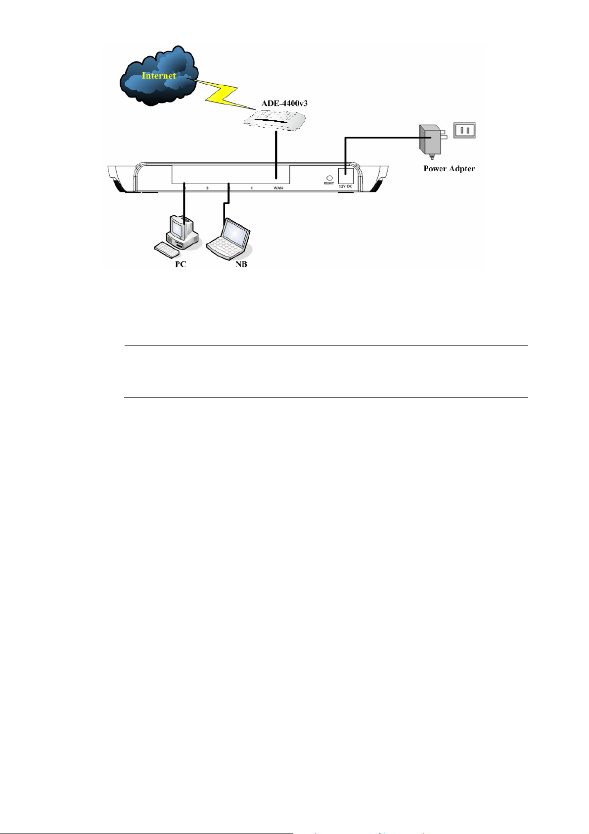
1.5 Getting Started
This is a step-by-step instruction on how to start using the router and get connected to the
Internet.
1) Setup your network as shown in the setup diagram below.
8
Page 9
2) Then, you need to setup your LAN PC clients so that it can obtain an IP address
automatically. By default the XRT-401E’s DHCP server is enabled so that you can obtain
an IP address automatically.
Please make sure that the XRT-401E’s DHCP server is the only DHCP
"Note
server available on your LAN. If there is another DHCP on your network,
then you’ll need to switch one of the DHCP servers off.
Step1ÎConfigure your PC to obtain an IP address automatically
This section will show you how to configure your PC’s so that it can obtain an IP address
automatically for either Windows 98/Me, 2000 or later operating systems. For other
operating systems (Macintosh, Sun, etc.), please follow the manufacturer’s instructions.
The following is a step-by-step illustration on how to configure your PC to obtain an IP
address automatically for 2a) Windows XP, 2b) Windows 2000, and 2c) Windows 98/Me
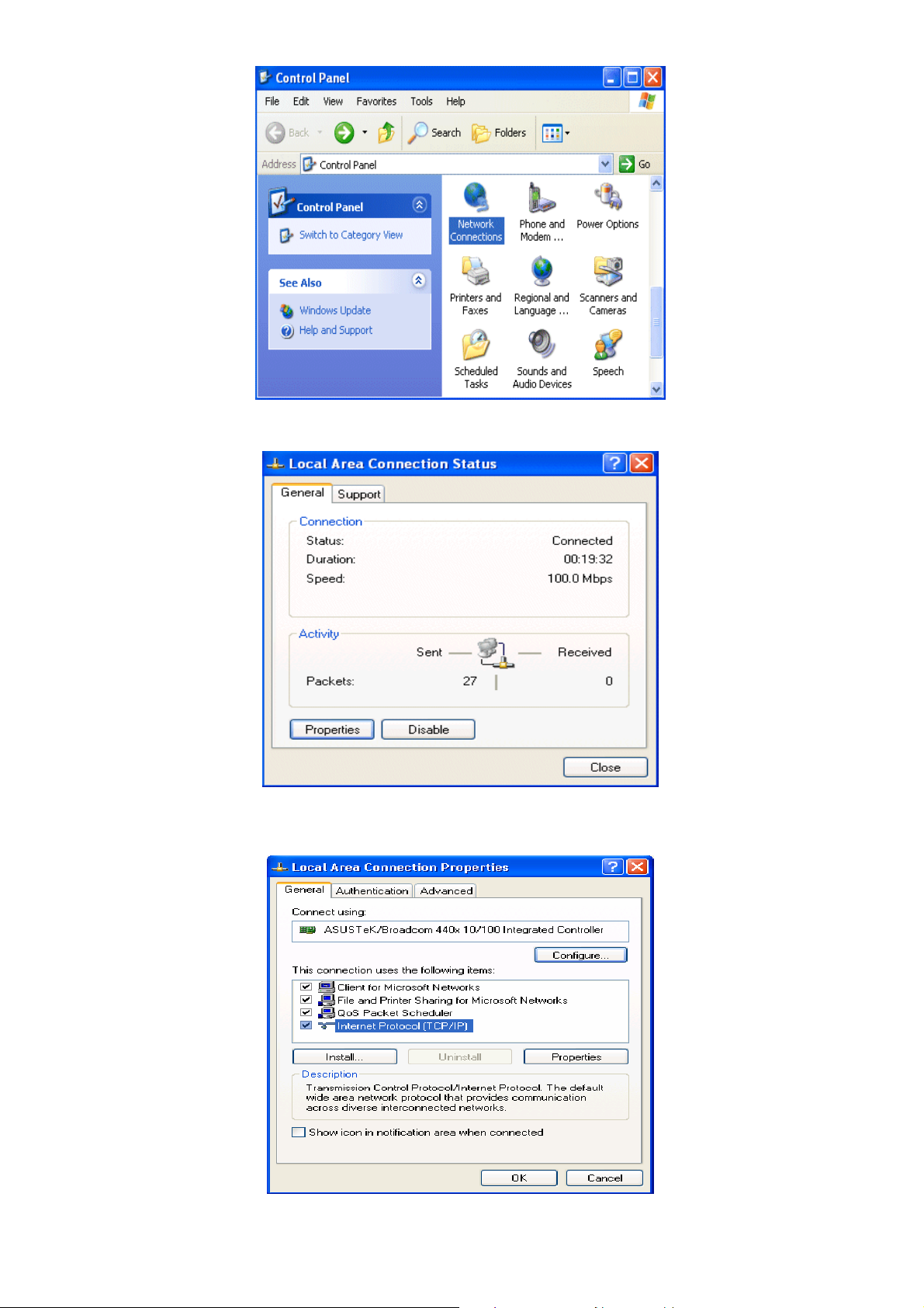
2a) Configuring PC in Windows XP
1. Go to Start / Control Panel (in Classic View). In the Control Panel, double-click on
Network Connections
2. Double-click Local Area Connection.
9
Page 10
3. In the Local Area Connection Status window, click Properties.
4. Select Internet Protocol (TCP/IP) and click Properties.
10
Page 11
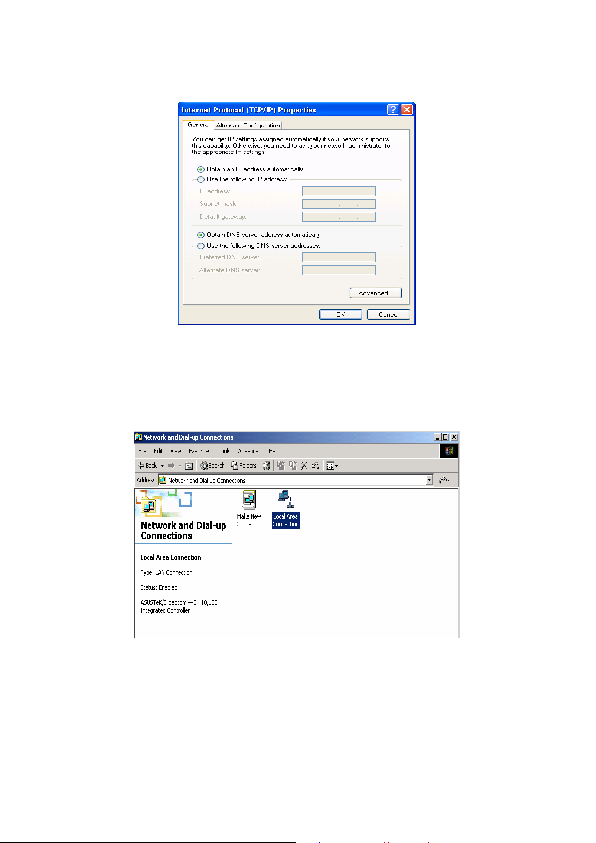
5. Select the Obtain an IP address automatically and the Obtain DNS server address
automatically radio buttons.
6. Click OK to finish the configuration.
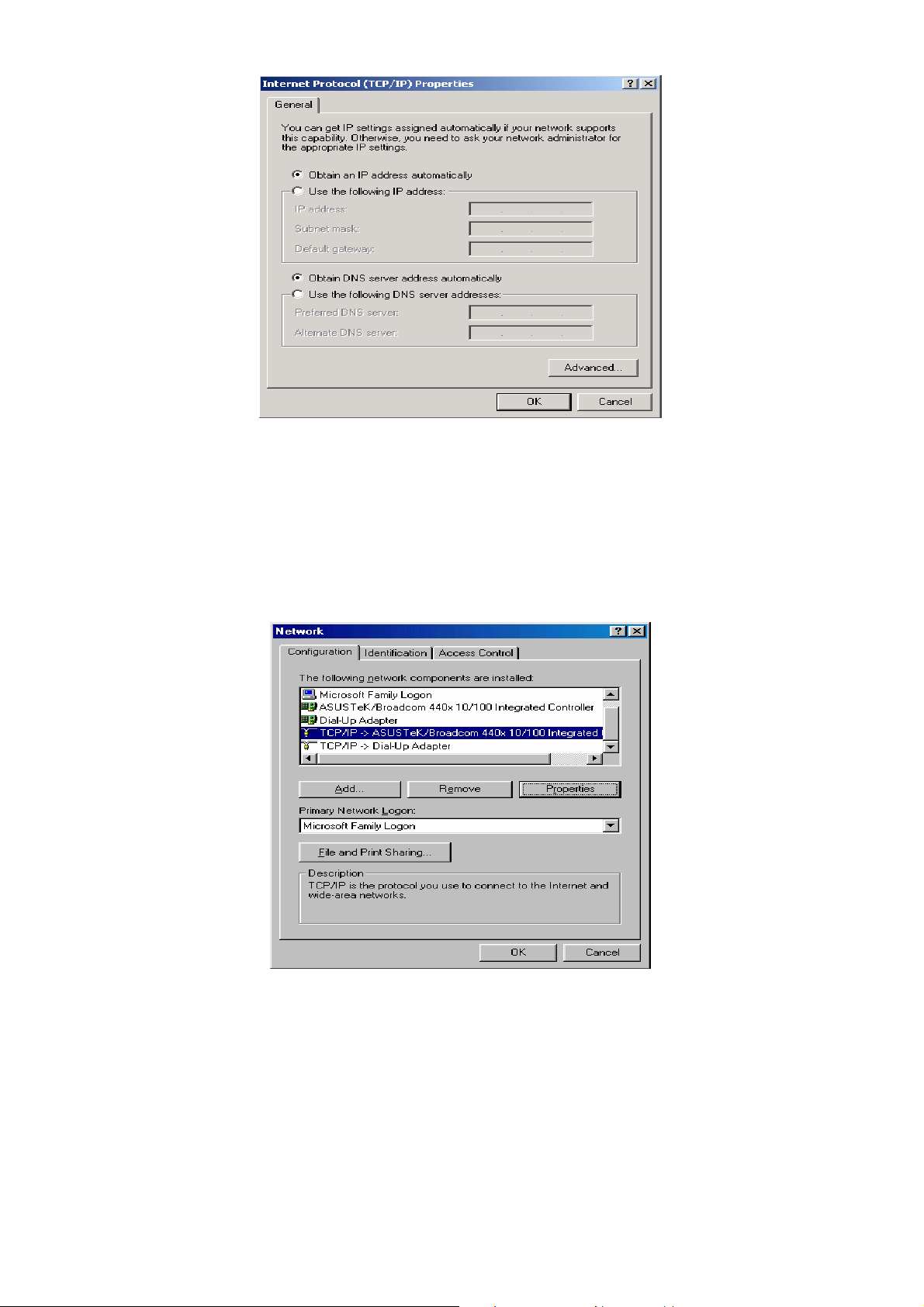
2b) Configuring PC in Windows 2000
1. Go to Start / Settings / Control Panel. In the Control Panel, double-click on Network
and Dial-up Connections.
2. Double-click Local Area Connection.
3. In the Local Area Connection Status window click Properties.
4. Select Internet Protocol (TCP/IP) and click Properties.
5. Select the Obtain an IP address automatically and the Obtain DNS server address
automatically radio buttons.
6. Click OK to finish the configuration.
11
Page 12
2c) Configuring PC in Windows 98/Me
1. Go to Start / Settings / Control Panel. In the Control Panel, double-click on Network
and choose the Configuration tab.
2. Select TCP/IP Æ NE2000 Compatible, or the name of your Network Interface Card
(NIC) in your PC.
3. Select the Obtain an IP address automatically radio button.
4. Then select the DNS Configuration tab.
5. Select the Disable DNS radio button and click OK to finish the configuration.
12
Page 13
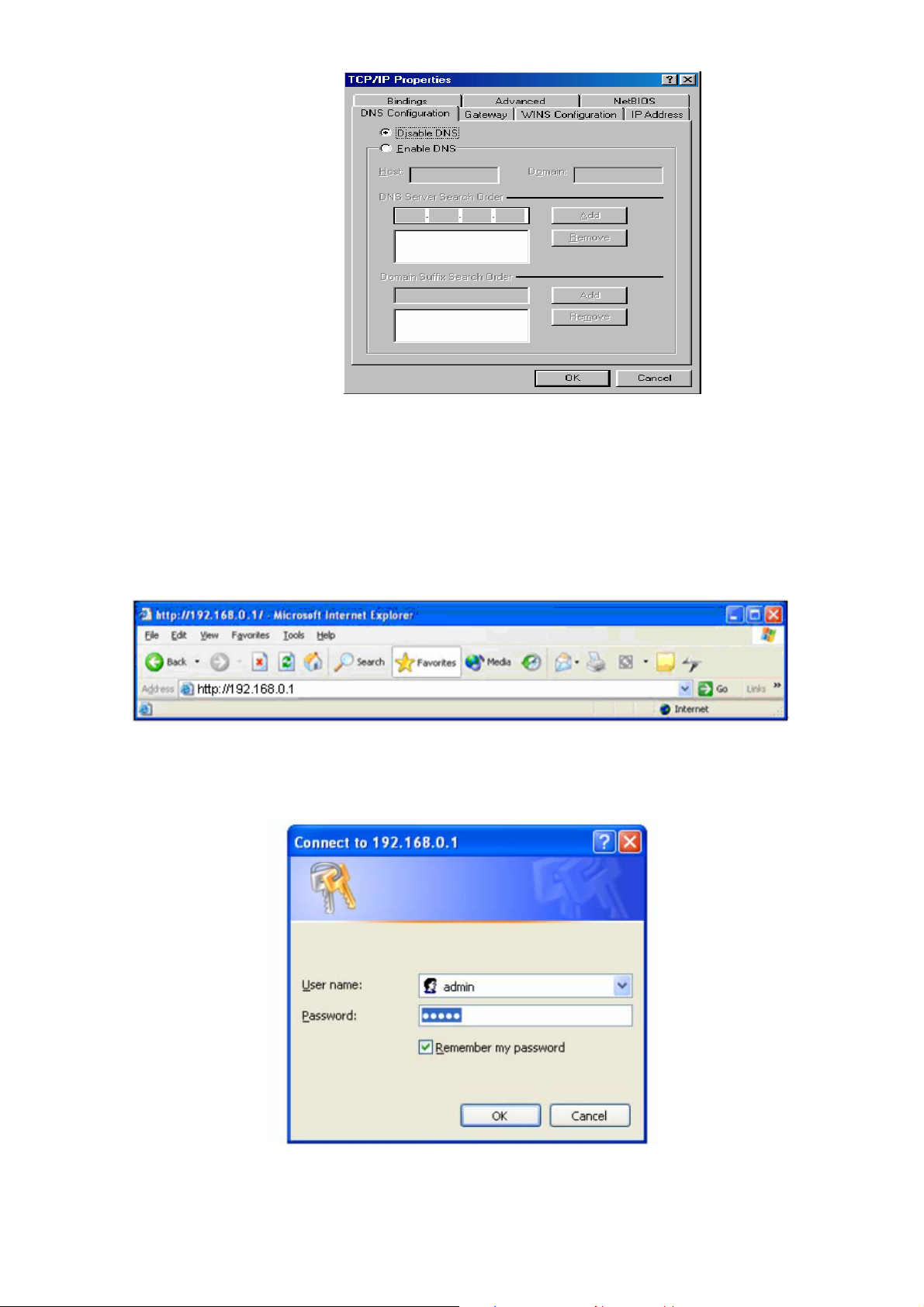
Step2Î Configuring with Web Browser
Once your PC has obtained an IP address from your router, enter the default IP address
“http: //192.168.01” (XRT-401E’s LAN IP address) into your PC’s web browser and press
<enter>
Save this address in your Favorites for future reference.
At the User name prompt, type “admin”. And the Password prompt, type “admin”. You
can change these later if you wish. Click “OK”.
13
Page 14
Chapter2 Wizard
The Wizard section is designed to get you using XRT-401E as quick as possible. In the
Wizard, you are required to fill in only the information necessary to access the Internet.
Once you click on the Wizard in the web page, you should see the screen below.
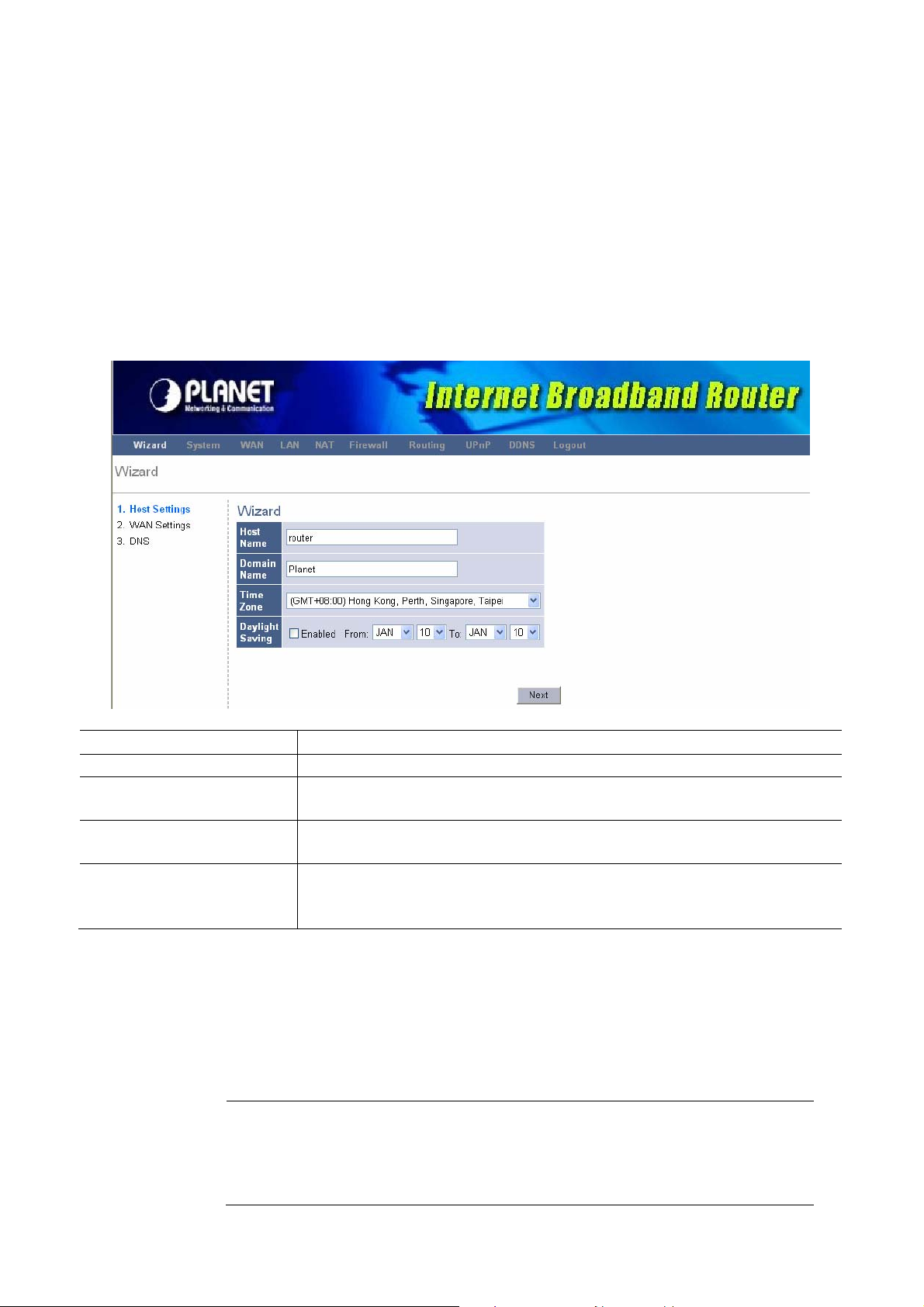
Step 1) Host Settings
The Host Settings allows your router to set up Host name and Domain name, it also can set
up its Time Zone and Daylight Saving Time, these will affect functions such as Log entries
and Firewall settings.
Parameter Description
Host Name
Domain Name
Time Zone
Daylight Savings
Click on NEXT to proceed to the next page (step 2) WAN Settings.
Step 2) WAN Settings
In this section you have to select one of these types of connections that you will be using to
connect your XRT-401E’s WAN port to your ISP (see screen below).
"Note
Different ISP’s require different methods of connecting to the Internet,
please check with your ISP as to the type of connection it requires.
This is optional. You can specify a Host name for XRT-401E.
This is optional. You can specify a Domain name to annotate
your LAN area.
Select the time zone of the country where you currently are. The
router will set its time based on your selection.
The XRT-401E can also take Daylight savings into account. If
you wish to use this function, you must select the enable box to
enable your daylight saving configuration.
14
Page 15
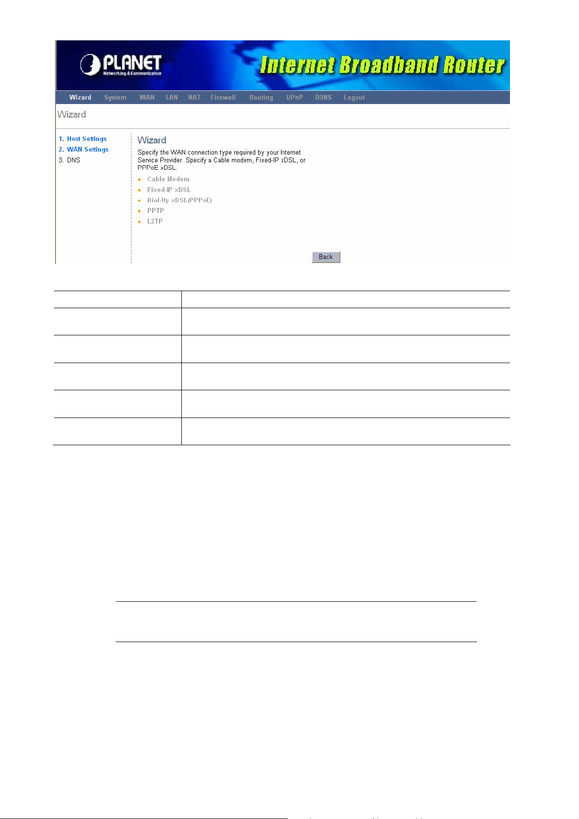
Parameter Description
2.1 Cable Modem
Your ISP will automatically give you an IP address.
2.2 Fixed-IP xDSL
2.3 Dial-Up xDSL
(PPPoE)
2.4 PPTP
2.5 L2TP
Click on one of the WAN types and then proceed to the manual’ s relevant sub-section (2.1,
2.2, 2.3, 2.4 or 2.5). Click on Back to return to the previous screen.
Your ISP has given you an IP address already
Your ISP requires you to use a Point-to-Point Protocol over
Ethernet (PPPoE) connection.
Your ISP requires you to use a Point-to-Point Tunneling
Protocol (PPTP) connection.
Layer 2 Tunneling Protocol is a common connection method
used in xDSL connections.
2.1 Cable Modem
Choose Cable Modem if your ISP will automatically give you an IP address. Some ISP’s
may also require that you fill in additional information such as MAC address (see screen
below).
The MAC address section is optional and you can skip this section if
"Note
your ISP does not require these settings for you to connect to the
Internet.
15
Page 16
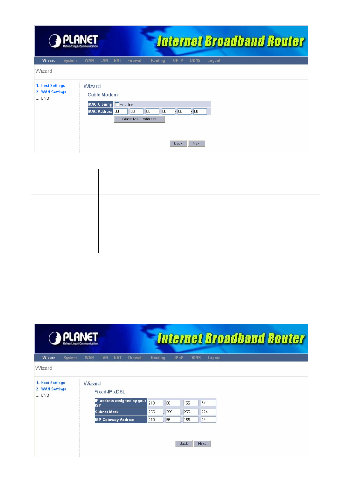
Parameter Description
MAC Cloning
MAC Address
If you want to clone your PC’s MAC address to XRT-401E, you must
enable it first.
Your ISP may require a particular MAC address in order for you to
connect to the Internet. This MAC address is the PC’s MAC address
that your ISP had originally connected your Internet connection to.
Type in this MAC address in this section or use the Clone MAC
Address button to replace the WAN MAC address with the MAC
address of that PC (you have to be using that PC for the Clone MAC
Address button to work).
2.2 Fixed-IP xDSL
Select Fixed-IP xDSL if your ISP has given you a specific IP address to use. Your ISP
should provide all the information required in this section.
16
Page 17
Parameter Description
IP address assigned by
your ISP
Subnet Mask
ISP Gateway Address
This is the IP address that your ISP has given you.
Enter the Subnet Mask provided by your ISP.
(e.g. 255.255.255.0)
This is the ISP’s IP address gateway.
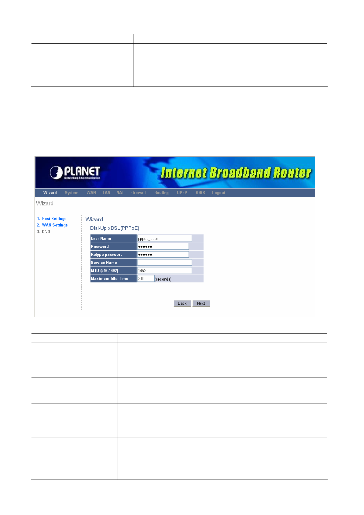
2.3 Dial-Up xDSL(PPPoE)
Select Dial-Up xDSL (PPPoE) if your ISP requires the PPPoE protocol to connect you to
the Internet. Your ISP should provide all the information required in this section.
Parameter Description
User Name
Password
Retype Password
Service Name
MTU
Maximum Idle Time
Enter the User Name provided by your ISP for the PPPoE
connection.
Enter the Password provided by your ISP for the PPPoE
connection.
Re-enter the Password for confirmation.
This is optional. Enter the Service name should your ISP
requires it, otherwise leave it blank.
This is optional. You can specify the maximum size of your
transmission packet to the Internet. Leave it as it is if you do
not wish to set a maximum packet size. (The default settings is
1492)
You can specify an idle time threshold (seconds) for the WAN
port. This means if no packets have been sent (no one using
the Internet) during this specified period, the router will
automatically disconnect the connection with your ISP. (The
default settings is 300 seconds)
17
Page 18
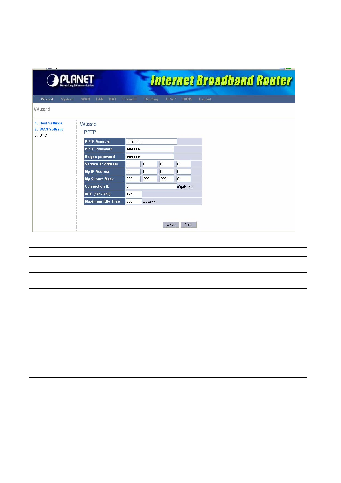
2.4 PPTP
Select PPTP if your ISP requires the PPTP protocol to connect you to the Internet. Your
ISP should provide all the information required in this section.
Parameter Description
PPTP Account
PPTP Password
Retype Password
Service IP Address
My IP Address
My Subnet Mask
Connection ID
MTU
Maximum Idle Time
Enter the PPTP Account provided by your ISP for the PPTP
connection.
Enter the Password provided by your ISP for the PPTP
connection.
Re-enter the Password for confirmation.
Specify PPTP Server IP address that you want to connect to.
This is the IP address that your ISP has given you to establish
a PPTP connection.
Enter the Subnet Mask provided by your ISP.
(e.g. 255.255.255.0)
This is the ID given by ISP. This is optional.
This is optional. You can specify the maximum size of your
transmission packet to the Internet. Leave it as it is if you do
not wish to set a maximum packet size. (The default setting is
1460)
You can specify an idle time threshold (seconds) for the WAN
port. This means if no packets have been sent (no one using
the Internet) during this specified period, the router will
automatically disconnect the connection with your ISP. (The
default settings is 300 seconds)
18
Page 19

2.5 L2TP
Select L2TP if your ISP requires the L2TP protocol to connect you to the Internet. Your ISP
should provide all the information required in this section.
Parameter Description
L2TP Account
L2TP Password
Retype Password
Service IP Address
My IP Address
My Subnet Mask
MTU
Maximum Idle Time
Step 3) DNS
A Domain Name System (DNS) server is like an index of IP addresses and W eb addresses.
If you type a Web address into your browser, such as www.router.com, a DNS server will
find that name in its index and the matching IP address. Most ISPs provide a DNS server
Enter the L2TP Account provided by your ISP for the PPTP
connection.
Enter the Password provided by your ISP for the L2TP
connection.
Re-enter the Password for confirmation.
Specify L2TP Server IP address that you want to connect to.
This is the IP address that your ISP has given you to establish
a L2TP connection.
Enter the Subnet Mask provided by your ISP. (e.g.
255.255.255.0)
This is optional. You can specify the maximum size of your
transmission packet to the Internet. Leave it as it is if you do
not wish to set a maximum packet size. (Default setting is
1460)
You can specify an idle time threshold (seconds) for the WAN
port. This means if no packets have been sent (no one using
the Internet) during this specified period, the router will
automatically disconnect the connection with your ISP. (The
default settings is 300 seconds)
19
Page 20
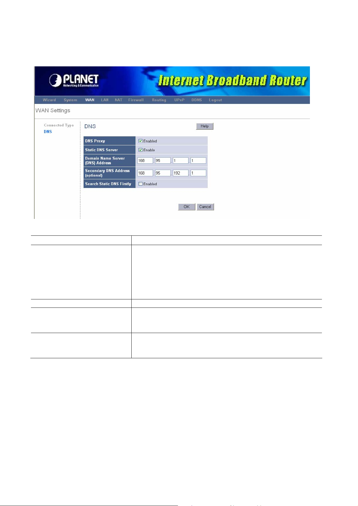
for speed and convenience. If your Service Provider connects you to the Internet with
dynamic IP settings, it is likely that the DNS server IP address is provided automatically.
However, if there is a DNS server that you would rather use, you need to specify the IP
address of that DNS server here.
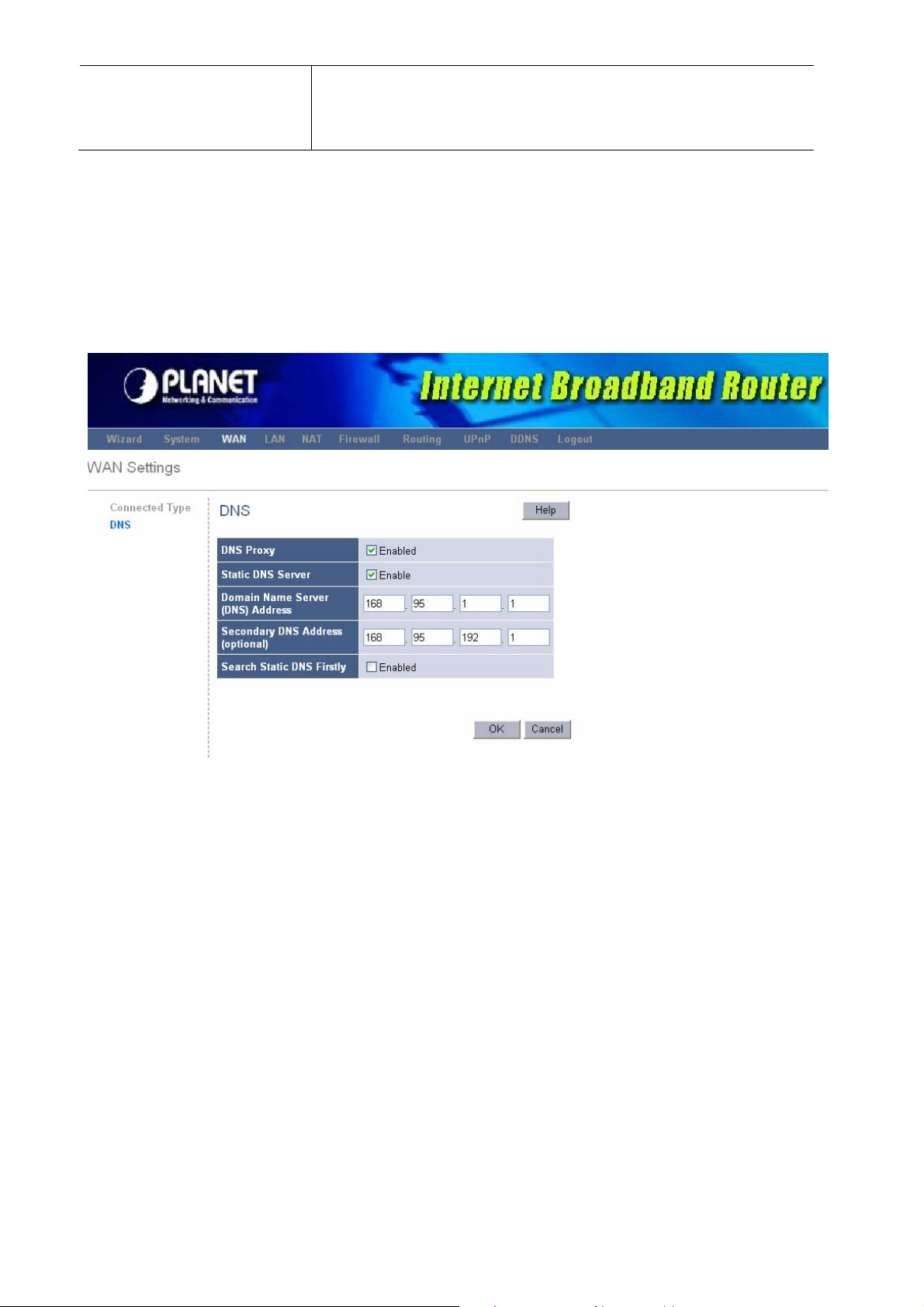
Parameter Description
DNS Proxy
Static DNS Server
Primary DNS Address
Secondary DNS Address
Click <Finish> when you have finished the configuration above. Congratulations! You
have completed the connection configuration. You can start using the router now.
Select <Enabled> that all DNS requests to a specific
Domain Name will be routed to the XRT-401E’s IP
address. If you want to use the DNS Proxy function of the
device, the end user’s main DNS server IP address
should be the same IP Address as the device.
Select “Enabled” to allow configuring DNS manually.
This is the ISP’s DNS server IP address that they gave
you; or you can specify your own preferred DNS server IP
address
This is optional. You can enter another DNS server’s IP
address as a backup. The secondary DNS will be used if
the above DNS fail.
Chapter 3 Advance Features
If you have already configured the Wizard, you do NOT need to configure anything for you
to start using the Internet.
Advance features that allow you to configure the router to meet your network’s needs such
20
Page 21

as: Special Applications, Port Mapping, DMZ, Virtual Servers, ALG, and Firewall option.
Below is a general description of what advance functions are available for this broadband
router.
Parameter Description
3.1 System
3.2 WAN
3.3 LAN
3.4 NAT
3.5 Firewall
3.6 Routing
3.7 UPnP
3.8 DDNS
This section allows you to set XRT-401E’s system settings, password
and Remote Management Administrator, it also allows you to check
system status and log, and provide you the configuration tools.
This section allows you to select the connection method in order
to establish a connection with your ISP (same as the Wizard section)
You can specify the LAN segment’s IP address, subnet Mask,
enable/disable DHCP and select an IP range for your LAN, you also
can check DHCP client list in here.
You can configure the Virtual Server, Special Applications, Port
Mapping, ALG and DMZ functions in this section. This allows you to
specify what user/packet can pass your router’s NAT.
The Firewall section allows you to configure Firewall, Client Filtering,
URL Filtering and MAC Control.
You can configure Static Routing in this section, and check the
concurrent Routing Table.
The UPnP section allows you to enable and configure UPnP function.
You can configure DDNS service in this section.
Select one of the above advance features selections and proceed to the manual’s relevant
subsection.
3.1 System
This section allows you to set XRT-401E’s system settings, password and Remote
Management Administrator, it also allows you to check system status and log, and provide
you the configuration tools.
Parameter Description
3.1.1 System Status
3.1.2 System Settings
3.1.3 Administrator
Settings
You can check system information in here, including
system status and concurrent hardware information.
This section Includes Host Name, Domain Name, Time
Zone, Daylight Saving and NAT enable/disable.
Allows you to set user name, password and the idle time
out, you can specify a Host IP address that can perform
3.1.4 Firmware Upgrade
remote management functions.
This section allows you to upgrade the router’s firmware
21
Page 22
and display the concurrent firmware version.
3.1.5 Configuration Tools
3.1.6 System Log
This section allows you to backup or restore the router’s
configuration. It also allows you to restart router or reset
it to factory default setting.
This section shows the current system and security log
of XRT-401E, you also can specify a syslog server to
save the log remotely.
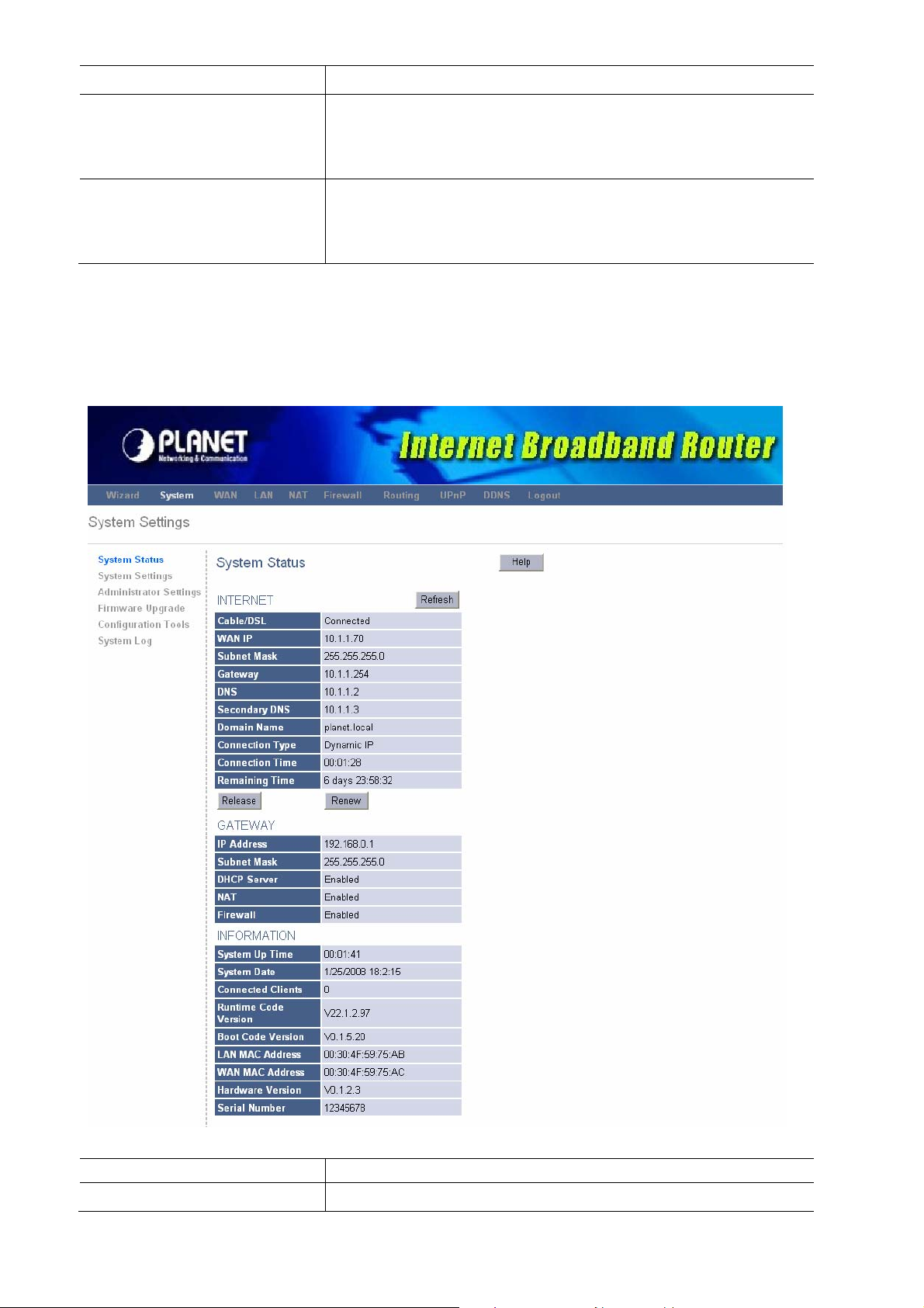
3.1.1 System Status
The section allows you to check XRT-401E system status and concurrent hardware
information.
Parameter Description
INTERNET
This item shows XRT-401E’s current device settings,
22
Page 23

including the current WAN IP Address,Subnet Mask,
Gateway, DNS and Connection Type.
GATEWAY
INFORMATION
This item displays XRT-401E’s current device settings,
including IP Address, Subnet Mask, DHCP Server,
NAT and Firewall Status.
This item displays XRT-401E hardware device
Settings, including Connected Clients, Runtime Code
Version and MAC Address.
3.1.2 System Settings
The system screen allows you to specify a time zone, Host Name and Domain Name, and
enable or disable NAT function of XRT-401E.
Parameter Description
Host Name
Domain Name
Set Time Zone
Daylight Saving
Optional. You can specify a Host name for XRT-401E.
Optional. You can specify a Domain name to annotate
your LAN area.
Select the time zone of the country where you are
currently are. The router will set its time based on your
selection.
The XRT-401E can also take Daylight savings into
account. If you wish to use this function, you must select
the enable box to enable your daylight saving
configuration.
23
Page 24

NAT
Select to enable or disable NAT function.
3.1.3 Administrator Settngs
The Administrator Settings function allows you to design user name, password and the idle
time, it also can allow you to configure Remote Management function.
Parameter Description
Password Settings
User Name
Current assword
Password
Re-type Password
Remote Management
Enable
IP Address
To specify a login name, the default is admin.
Enter the current password for verification.
Type a new password in order to access the web-based
management website.
Re-type the password for confirmation.
To enable Remote Management function.
This is the IP address of the host in the Internet that will
have management/configuration access to XRT-401E
from a remote site. If the IP Address is 0.0.0.0, this
24
Page 25
means anyone can access the router’s web console from
a remote location
Port
The port number of remote management web interface
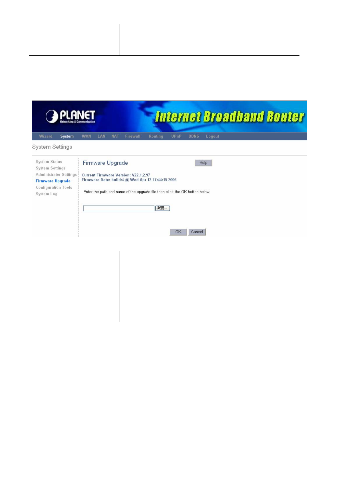
3.1.4 Firmware Upgrade
This page allows you to upgrade the router’s firmware.
Parameter Description
Firmware Upgrade
This tool allows you to upgrade XRT-401E’s system
firmware. To upgrade the firmware of your Broadband
router, you need to download the firmware file to your
local hard disk, and enter that file name and path in the
appropriate field on this page. You can also use the
Browse button to find the firmware file on your PC.
3.1.5 Configuration Tool
The Configuration Tools screen allows you to save (Backup) the router’s current
configuration setting. Saving the configuration settings provides an added protection and
convenience, if the problems occur with the router and you have to reset to factory default.
When you save the configuration setting (Backup) you can re-load the saved configuration
into the router through the Restore selection. If extreme problems occur, you can use the
Restore to Factory Defaults selection, this will set all configurations to its original default
settings (e.g. when you first purchased the router). You also can Restart the router’s
system if any problems exist.
25
Page 26

Parameter Description
Restart System
In the event that the system stops responding correctly or
in some way stops functioning, you can perform a reset.
Your settings will not be changed.
Restore Factory Default
If extreme problems occur, you can use the Restore
Factory Default selection, this will set all configurations to
its original default settings (e.g. when you first purchased
the router).
Backup Settings
Backup the configuration settings provide an added
protection and convenience, if the problems occur with the
router and you have to reset to factory default.
Restore Settings
When you save the configuration setting (Backup) you can
reload the saved configuration into the router through the
Restore Settings selection.
3.1.6 System Log
The Logs record various types of activity on XRT-401E. This data is useful for
troubleshooting,but enabling all logs will generate a large amount of data and adversely
affect performance. Since only a limited amount of log data can be stored in XRT-401E, log
data can also be e-mailed to your PC or sent to a Syslog Server.
26
Page 27
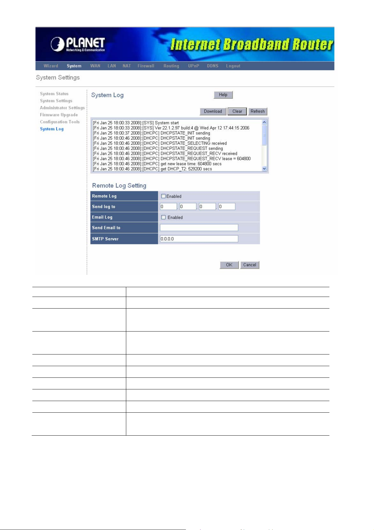
Parameter Description
System Log
System Log
Security Log
Remote Log Setting
Remote Log
Send Log to
Email Log
Send Email to
SMTP Server
The Log records the router operating of activity on
XRT-401E.
The Log shows the current security log of XRT-401E. At
the top of the content, the security log can be saved.
Select <Enabled> to allow saving the log to Syslog Server.
Enter the IP address of your Syslog Server.
Select <Enabled> to allow mailing the log to specific user.
Enter the mail address that your want to mail log to.
Enter the address or IP address of the SMTP (Simple Mail
Transport Protocol) Server you use for outgoing E-mail.
3.2 WAN
Use the WAN Settings screen if you have already configured the Wizard section and you
27
Page 28

would like to change your Internet connection type. The WAN Settings screen allows you to
specify the type of WAN port connect you want to establish with your ISP. The WAN
settings offer the following selections for the router’s WAN port, Dynamic IP, Static IP
Address, PPPoE, PPTP, L2TP and DNS.
Parameter Description
3.2.1 Dynamic IP
3.2.2 Static IP address
3.2.3 PPPoE
3.2.4 PPTP
3.2.5 L2TP
Your ISP will automatically give you an IP address
Your ISP has given you an IP address already
Your ISP requires PPPoE connection
Your ISP requires you to use a Point-to-Point Tunneling
Protocol (PPTP) connection.
Your ISP requires L2TP connection.
3.2.1 Dynamic IP
Choose the Dynamic IP selection if your ISP will automatically give you an IP address.
Some ISP’s may also require that you fill in additional information such as MAC address
(see chapter 2 “Cable Modem” for more detail). Select Big Pond if your ISP requires the Big
Pond protocol to connect you to the Internet.
28
Page 29
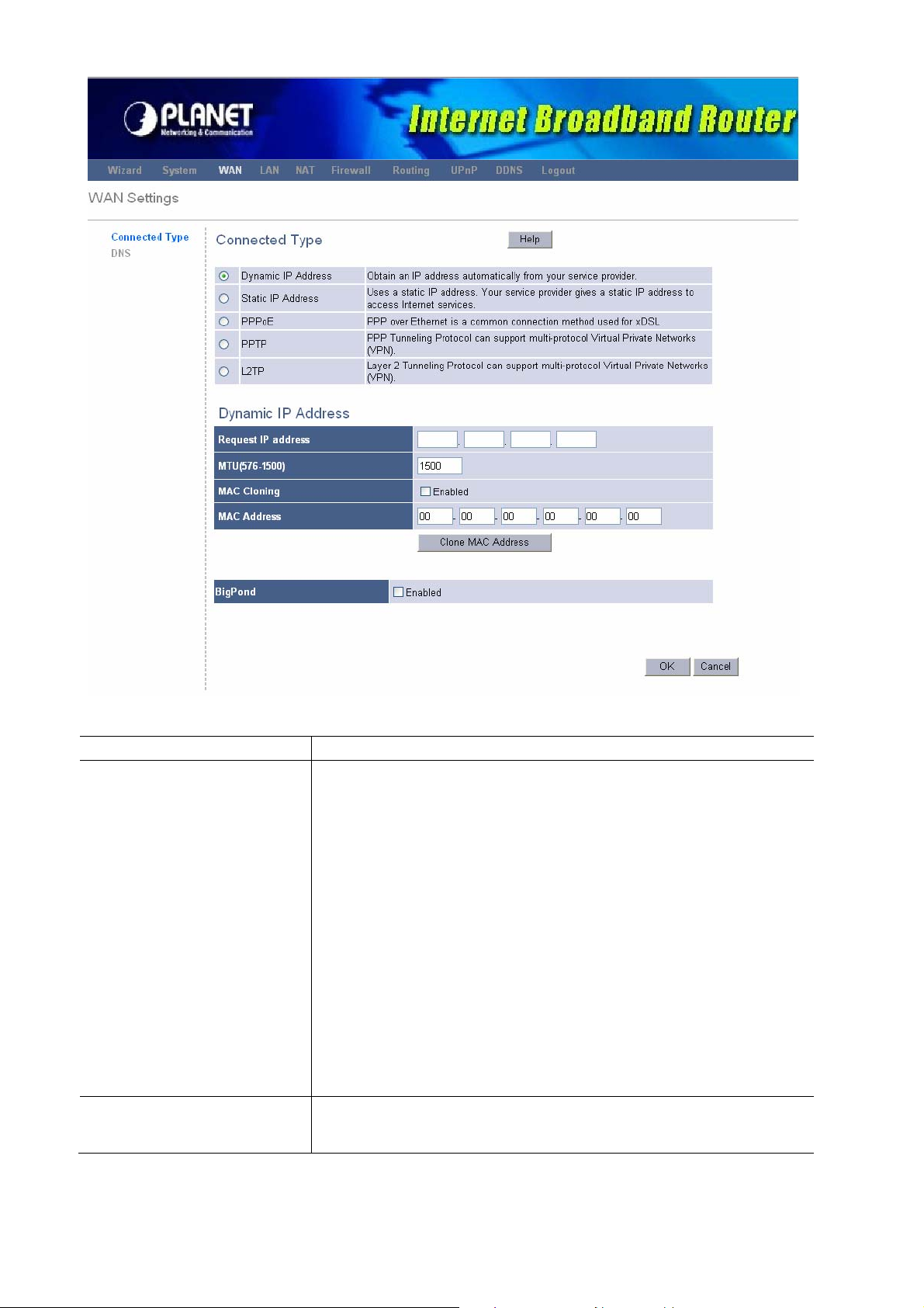
Parameter Description
Dynamic IP
Your ISP will automatically give you an IP address
Clone MAC Address
Select <Enabled> to allow replacing the WAN MAC
address with a specific MAC address.
MAC Address
Your ISP may require a particular MAC address in order for
you to connect to the Internet. This MAC address is the
PC’s MAC address that your ISP had originally connected
your Internet connection to. Type in this MAC address in
this section or use the “Clone MAC Address” button to
replace the WAN MAC address with the MAC address of
that PC.
BigPond
Select <Enabled> if your ISP requires the Big Pond
protocol to connect you to the Internet.
29
Page 30

3.2.2 Static IP
Select Static IP address if your ISP has given you one or more IP address for you to use.
Your ISP should provide all the information required in this section. (See chapter 2 “Fixed
IP” for more detail)
Parameters Description
Static IP
Your ISP has given you an IP address already, and you
must type in the related IP address such as IP Address,
Subnet Mask and Gateway.
Does ISP provide more
IP addresses?
More IP address
Select <Yes> if your ISP provide more than one IP
address.
Type the other IP address that ISP provide to you, this IP
address will be useful in DMZ function.
3.2.3 PPPoE (PPP over Ethernet)
Select PPPoE if your ISP requires the PPPoE protocol to connect you to the Internet. Your
ISP should provide all the information required in this section. (See chapter 2 “PPPoE” for
more detail)
30
Page 31
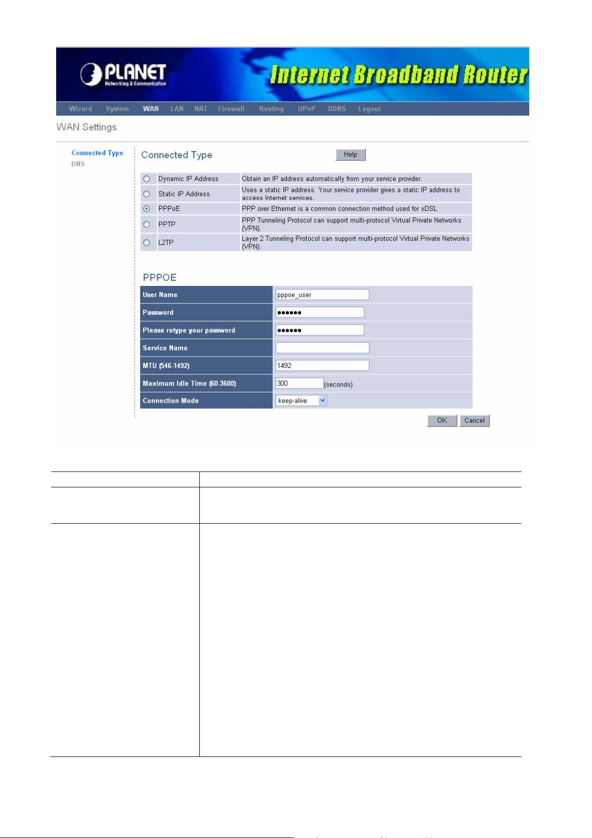
PPPoE
Parameter Description
Your ISP requires PPPoE connection, and you must type in
the User Name, Password that your ISP provide.
Connection Mode
Select the desired option:
Keep-alive (maintain connection)
The connection will never be disconnected by this device. If
disconnected by your ISP, the connection will be
re-established immediately. (However, this does not
ensure that your Internet IP address will remain
unchanged.)
Auto-Connect
An Internet connection is automatically made when
required, and disconnected when idle for the time period
specified by the "Maximum Idle Time (60~3600)".
Manual-on
You must manually establish and terminate the connection.
31
Page 32
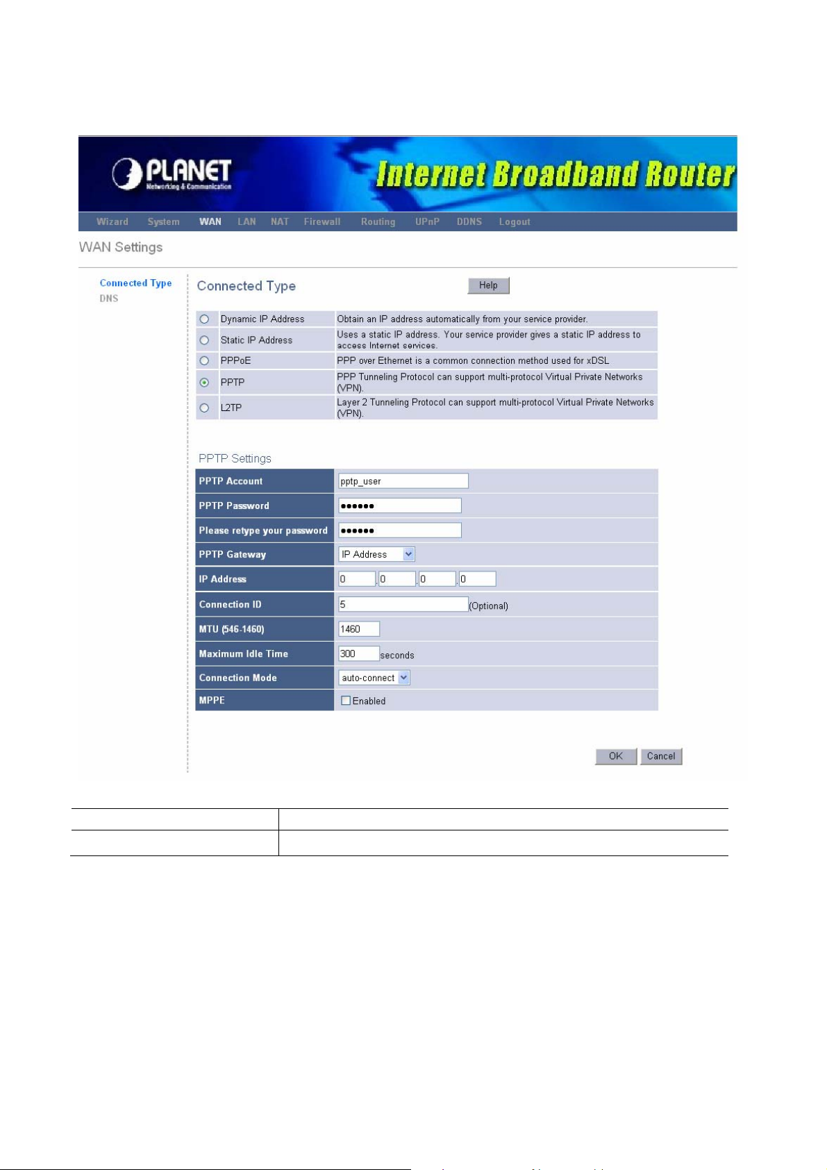
3.2.4 PPTP
Select PPTP if your ISP requires the PPTP protocol to connect you to the Internet. Your
ISP should provide all the information required in this section.
Parameter Description
WAN Interface Settings
To configure WAN Interface IP
32
Page 33

Dynamic IP
The ISP requires you to obtain an IP address by DHCP
before connecting to the PPTP server.
Clone MAC Address
Select <Enabled> to allow replacing the WAN MAC
address with a specific MAC address.
MAC Address
Your ISP may require a particular MAC address in order for
you to connect to the Internet. This MAC address is the
PC’s MAC address that your ISP had originally connected
your Internet connection to. Type in this MAC address in
this section or use the “Clone MAC Address” button to
replace the WAN MAC address with the MAC address of
that PC.
Static IP
PPTP Settings
PPTP Account
PPTP Password
Retype Password
PPTP Gateway
Connection ID
Maximum Idle Time
The ISP gives you a static IP to be used to connect to the
PPTP server. You must type in the related IP address such
as IP Address, Subnet Mask and Gateway.
Enter the PPTP Account provided by your ISP for the
PPTP connection.
Enter the Password provided by your ISP for the PPTP
connection.
Re-enter the Password for confirmation.
If your LAN has a PPTP gateway, then enter that PPTP
gateway IP address or domain name here. If you do not
have a PPTP gateway then enter the ISP’s Gateway IP
address above or domain name.
This is the ID given by ISP. This is optional.
You can specify an idle time threshold (seconds) for the
WAN port. This means if no packets have been sent (no
Connection Mode
one using the Internet) during this specified period, the
router will automatically disconnect the connection with
your ISP.
Select the desired option:
Keep-alive (maintain connection)
The connection will never be disconnected by this device. If
disconnected by your ISP, the connection will be
reestablished immediately. (However, this does not ensure
that your Internet IP address will remain unchanged.)
Auto-Connect
An Internet connection is automatically made when
33
Page 34
required, and disconnected when idle for the time period
specified by the "Maximum Idle Time (60~3600)".
Manual-on
You must manually establish and terminate the connection.
MPPE
Select <Enabled> to enable “Microsoft Point to Point
Encryption” ability.
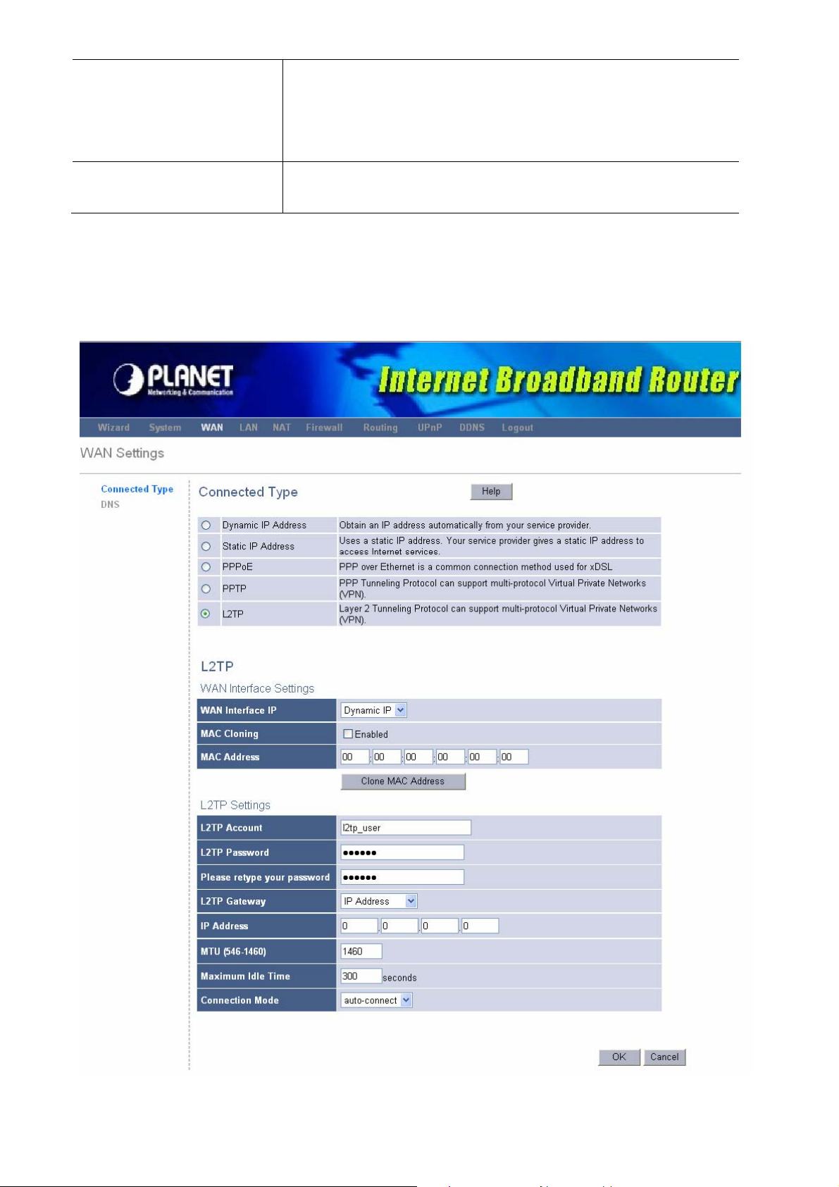
3.2.5 L2TP
Select L2TP if your ISP requires the L2TP protocol to connect you to the Internet. Your ISP
should provide all the information required in this section.
34
Page 35

Parameter Description
WAN Interface Settings
To configure WAN Interface IP
Dynamic IP
The ISP requires you to obtain an IP address by DHCP
before connecting to the L2TP server.
MAC Cloning
Select <Enabled> to allow replacing the WAN MAC
address with a specific MAC address.
MAC Address
Your ISP may require a particular MAC address in order for
you to connect to the Internet. This MAC address is the
PC’s MAC address that your ISP had originally connected
your Internet connection to. Type in this MAC address in
this section or use the “Clone MAC Address” button to
replace the WAN MAC address with the MAC address of
that PC.
Static IP
The ISP gives you a static IP to be used to connect to the
PPTP server. You must type in the related IP address such
as IP Address, Subnet Mask and Gateway.
L2TP Settings
L2TP Account
L2TP Password
Retype Password
L2TP Gateway
Maximum Idle Time
Connection Mode
Enter the L2TP Account provided by your ISP for the L2TP
connection.
Enter the Password provided by your ISP for the L2TP
connection.
Re-enter the Password for confirmation.
gateway IP address or domain name here. If you do not
have a L2TP gateway then enter the ISP’s Gateway IP
address above or domain name.
You can specify an idle time threshold (seconds) for the
WAN port. This means if no packets have been sent (no
one using the Internet) during this specified period, the
router will automatically disconnect the connection with
your ISP.
Select the desired option:
Keep-alive (maintain connection)
The connection will never be disconnected by this device. If
disconnected by your ISP, the connection will be
reestablished immediately. (However, this does not ensure
that your Internet IP address will remain unchanged.)
Auto-Connect
An Internet connection is automatically made when
required, and disconnected when idle for the time period
35
Page 36
specified by the "Maximum Idle Time (60~3600)".
Manual-on
You must manually establish and terminate the connection.
3.2.6 DNS
A Domain Name System (DNS) server is like an index of IP addresses and Web addresses.
If you type a Web address into your browser, such as www.router.com, a DNS server will
find that name in its index and the matching IP address. (See chapter 2 “DNS” for more
detail)
3.3 LAN
The LAN Port screen below allows you to specify a private IP address for your router’s LAN
ports as well as a subnet mask for your LAN segment.
3.3.1 LAN Setting
36
Page 37

Parameter Default Description
IP address
192.168.0.1 This is the router’s LAN port IP address (Your
LAN clients default gateway IP address)
IP Subnet Mask
DHCP Server
IP Pool
Starting/Ending
Address
Lease Time
255.255.255.0 Specify a Subnet Mask for your LAN segment
Enabled You can enable or disable the DHCP server. By
enabling the DHCP server the router will
automatically give your LAN clients an IP
address. If the DHCP is not enabled then you’ll
have to manually set your LAN client’s IP
addresses; make sure the LAN Client is in the
same subnet as this broadband router if you want
the router to be your LAN client’s default
gateway.
The IP range is
from 192.168.0.2
to 192.168.0.254.
The DHCP when enabled will temporarily give
You can select a particular IP address range for
your DHCP server to issue IP addresses to your
LAN Clients.
your LAN clients an IP address. In the Lease
Time setting you can specify the time period that
the DHCP lends an IP address to your LAN
clients. The DHCP will change your LAN client’s
IP address when this time threshold period is
reached
37
Page 38

3.3.2 DHCP Client List
You can check your current status of the DHCP client here, it also allow you to add the
client IP address with specific MAC address manually.
Parameter Description
DHCP Clinet List
Host Name
IP Address
MAC Address
Remainging Time
Staic
Static Client
Host Name
IP Address
MAC Address
The DHCP client list allows you to see which clients are
connected to the Router via IP address, host name,
remaing time and MAC address.You can select static to
fixed it
You can specify the current client to be a staic client.
This is optional, you can specify a host name for your
static client.
Fill in the IP address which you wish to be a static client.
Fill in the MAC address which you wish to be a static
client.
3.4 NAT
Network Address Translation (NAT) allows multiple users at your local site to access the
Internet through a single Public IP Address or multiple Public IP Addresses. NAT provides
Firewall protection from hacker attacks and has the flexibility to allow you to map Private IP
Addresses to Public IP Addresses for key services such as Websites and FTP. To meet
various field applications, XRT-401E NAT function can be disabled to as a regular router. If
NAT is disabled, all LAN side workstations must have valid IP addresses for Internet
38
Page 39

access. If the router is usedfor routing application, not for Internet access, then the NAT
function can be disabled.
Parameter Description
3.4.1 Virtual Server
You can have different services (e.g. email, FTP, Web
etc.) going to different service servers/clients in your LAN.
The Virtual Server allows you to re-direct a particular
service port number (from the Internet/WAN Port) to a
particular LAN IP address and its service port number.
3.4.2 Special Applications
3.4.3 Port Forwarding
3.4.4 ALG Setting
3.4.5 DMZ
Some applications require multiple connections, such as
Internet games, video conferencing, Internet telephony
and others. In this section you can configure the router
to support these types of applications.
You can have different services (e.g. email, FTP, Web
etc.) going to different service servers/clients in your LAN.
The Port Forwarding allows you to re-direct a particular
range of service port numbers (from the Internet/WAN
Ports) to a particular LAN IP address.
You can select special applications that need “Application
Layer Gateway” to support here.
The DMZ function allows you to re-direct all packets
going to your WAN port IP address to a particular IP
address in your LAN.
3.4.1 Virtual Server
Use the Virtual Server function when you want different servers/clients in your LAN to
handle different service/Internet application type (e.g. Email, FTP, Web server etc.) from
the Internet.Computers use numbers called port numbers to recognize a particular
service/Internet application type. The Virtual Server allows you to re-direct a particular
service port number (from the Internet/WAN Port) to a particular LAN private IP address
and its service port number.
39
Page 40
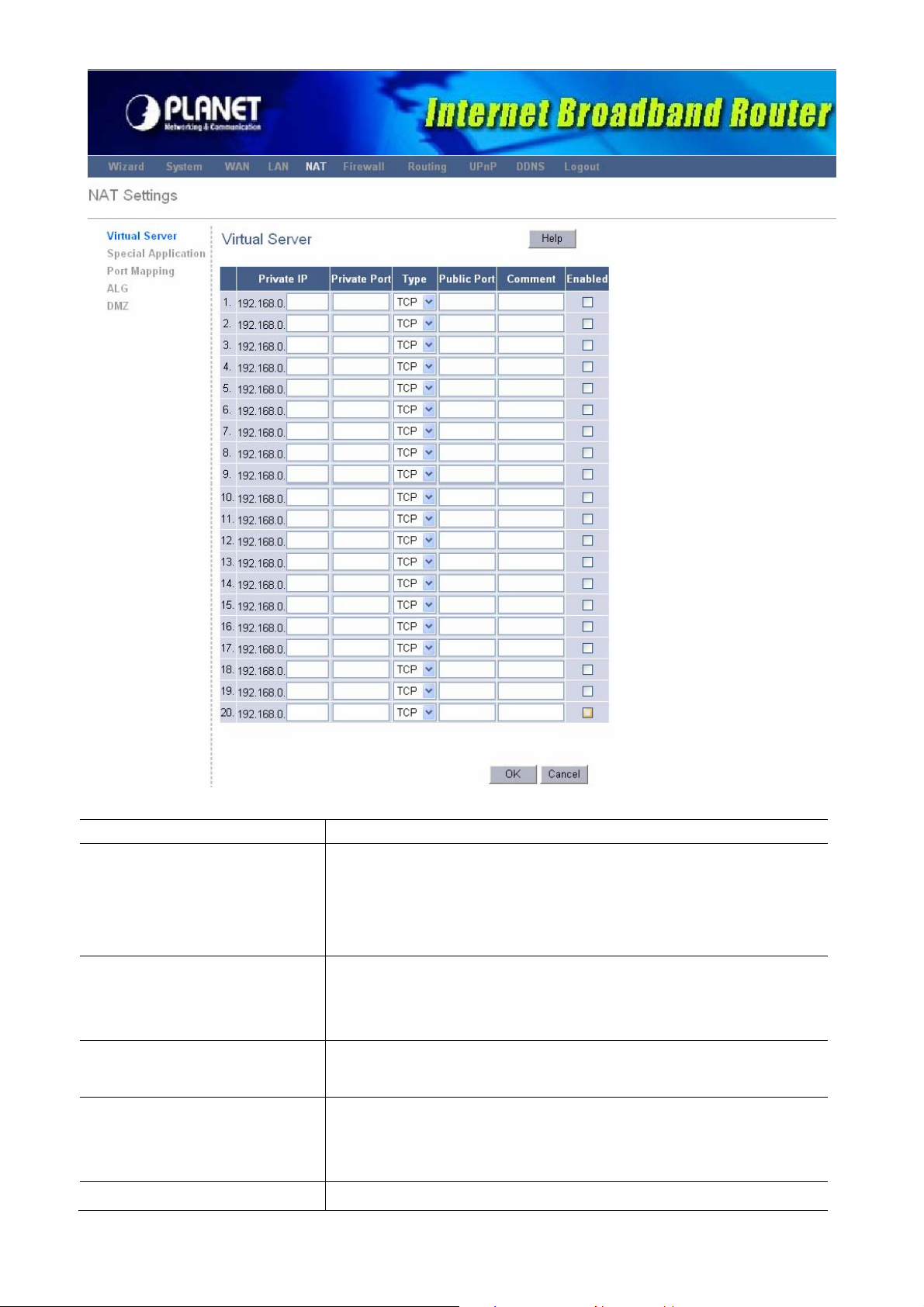
Parameter Description
Private IP
This is the LAN client/host IP address that the Public Port
number packet will be sent to.
Note: You need to give your LAN PC clients a fixed/static
IP address for Virtual Server to work properly.
Private Port
Type
Public Port
Comment
This is the port number (of the above Private IP host) that
the below Public Port number will be changed to when the
packet enters your LAN (to the LAN Server/Client IP)
Select the port number protocol type (TCP, UDP or both). If
you are unsure, then leave it to the default both protocols.
Enter the service (service/Internet application) port number
from the Internet that will be re-directed to the above
Private IP address host in your LAN
The description of this setting.
40
Page 41
Enable
To enable the rule of Virtual Server.
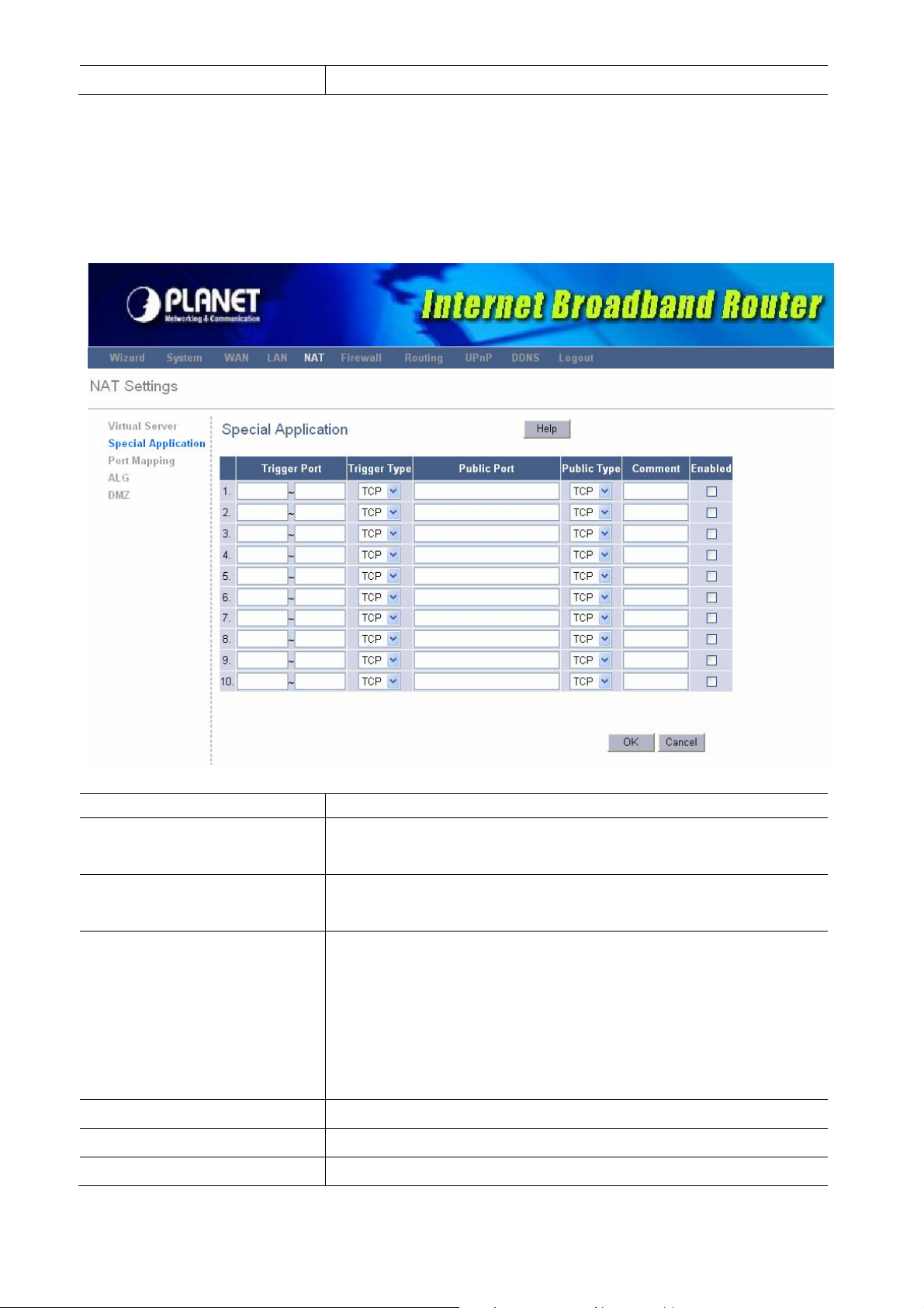
3.4.2 Special Applications
Some applications require multiple connections, such as Internet games, video
conferencing, Internet telephony and others. In this section you can configure the router to
support multiple connections for these types of applications.
Parameter Description
Trigger Port
Trigger Type
Public Port
Public Type
Comment
Enable
This is the out going (Outbound) range of port numbers for
this particular application
Select whether the outbound port protocol is “TCP”, “UDP”
or both.
Enter the In-coming (Inbound) port or port range for this
type of application (e.g. 2300-2400, 47624)
Note: Individual port numbers are separated by a comma
(e.g. 47624, 5775, 6541 etc.). To input a port range use a
“dash” to separate the two port number range (e.g.
2300-2400)
Select the Inbound port protocol type: “TCP”, “UDP” or both
The description of this setting.
To enable the rule of the Special Application function.
41
Page 42

Example: Special Applications
If you need to run applications that require multiple connections, then specify the port
(outbound) normally associated with that application in the "Trigger Port" field. Then select
the protocol type (TCP or UDP) and enter the public ports associated with the trigger port to
open them up for inbound traffic.
Example:
ID Trigger Port Trigger Type Public Port Public Type Comment
1 28800 UDP 2300-2400,47624 TCP MSN Game Zone
2 6112 UDP 6112 UDP Battle.net
In the example above, when a user trigger’s port 28800 (outbound) for MSN Game Zone
then the router will allow incoming packets for ports 2300-2400 and 47624 to be directed to
that user.
Note: Only one LAN client can use a particular special application at a time.
3.4.3 Port Forwarding
The Port Forwarding allows you to re-direct a particular range of service port numbers (from
the Internet/WAN Ports) to a particular LAN IP address. It helps you to host some servers
behind the router NAT firewall.
42
Page 43
Parameter Description
Server IP
This is the private IP of the server behind the NAT firewall.
Note: You need to give your LAN PC clients a fixed/static
IP address for Port Forwarding to work properly.
Mapping Ports
Type
Comment
Enable
The range of ports to be forward to the private IP.
This is the protocol type to be forwarded. You can choose
to forward “TCP” or “UDP” packets only or select “both” to
forward both “TCP” and “UDP” packets.
The description of this setting.
To enable the rule of Port Forwarding
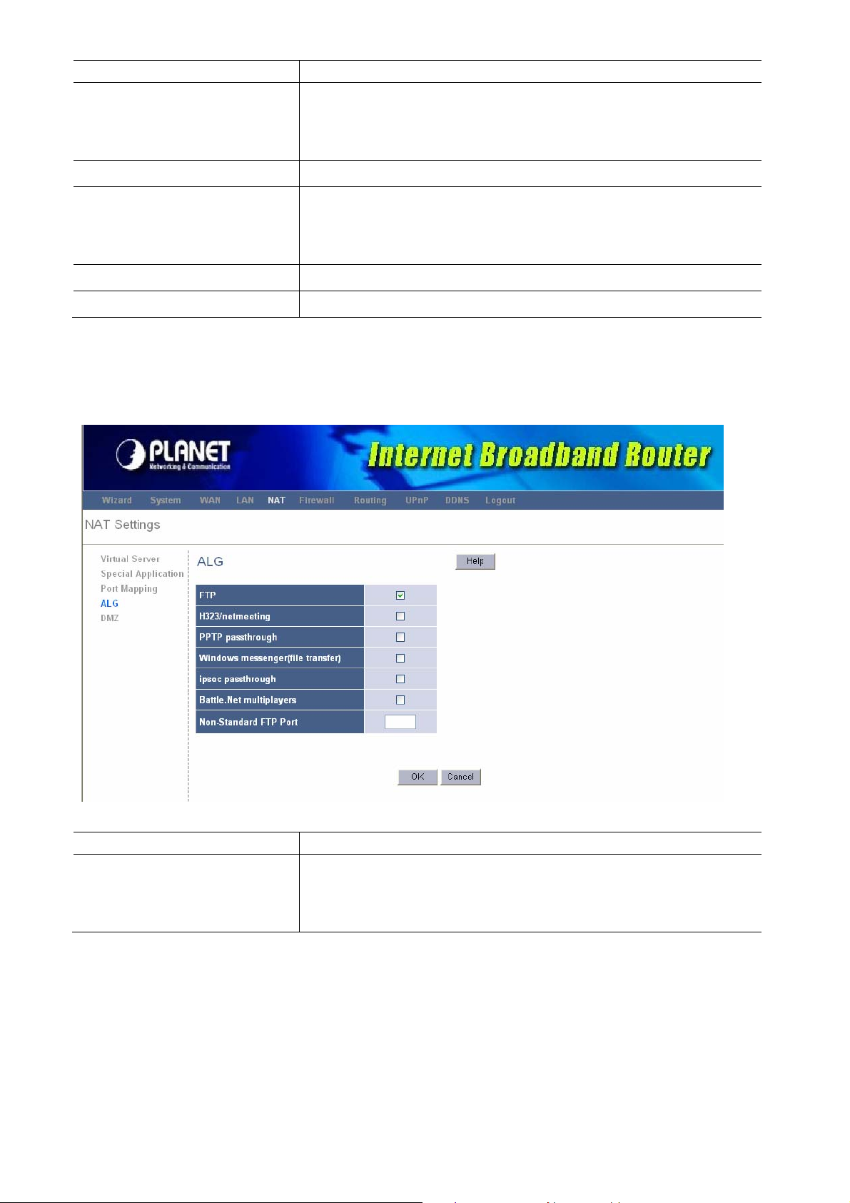
3.4.4 ALG Settings
You can select applications that need “Application Layer Gateway” to support.
Parameter Description
Enable
You can select to enable “Application Layer Gateway” of an
application and then the router will let that application
correctly pass though the NAT gateway.
3.4.5 DMZ
If you have a local client PC that cannot run an Internet application (e.g. Games) properly
from behind the NAT firewall, then you can open the client up to unrestricted two-way
Internet access by defining a DMZ Host. The DMZ function allows you to re-direct all
packets going to your WAN port IP address to a particular IP address in your LAN. The
43
Page 44

difference between the virtual server and the DMZ function is that the virtual server
re-directs a particular service/Internet application (e.g. FTP, websites) to a particular LAN
client/server, whereas DMZ re-directs all packets (regardless of services) going to your
WAN IP address to a particular LAN client/server.
Parameter Description
Enable
Public IP Address
IP Address of Virtual DMZ
Action
Enable/disable DMZ
The IP address of the WAN port or any other Public IP
addresses given to you by your ISP
Input the IP address of a particular host in your LAN that
will receive all the packets originally going to the WAN
port/Public IP address above.
Press <Add> to add DMZ rule.
3.5 Firewall
XRT-401E provides extensive firewall protection by restricting connection parameters, thus
limiting the risk of hacker attack, and defending against a wide array of common Internet
attacks.
Parameter Description
3.5.1 Firewall Options
3.5.2 Client Filtering
XRT-401E's firewall can block common hacker attacks and
can log the attack activities.
Client Filtering allows you to specify which hosts users can
or cannot access to certain Internet applications by IP
address.
44
Page 45

3.5.3 URL Filtering
URL Filtering allow you to specify which URLs can not be
accessed by users.
3.5.4 MAC Control
MAC Control allows you to specify which hosts users can
or cannot access to Internet by MAC address.
3.5.1 Firewall Options
XRT-401E's firewall can block common hacker attacks, including Denial of Service, Ping of
Death, Port Scan and Sync Flood. If Internet attacks occur the router can log the events.
Parameter Description
Firewall Options
Enable Hacker Attack Protect
Select it to enable Firewall Options function.
45
Page 46

Discard Ping From WAN
The router’s WAN port will not respond to any Ping
requests
Unallow to Ping the Gateway
Drop Port Scan Packets
Allow to Scan Security Port
(113)
Discard NetBIOS Packets
Accept Fragment Packets
Send ICMP packets when
error
Advanced settings
IP Spoofing
Smurf Attack
Ping of Death
Land Attack
Snork Attack
The router’s LAN port will not respond to any Ping
requests
Protection the router from Port Scan.
Select to allow Identification Protocol (Port 113) to be
scanned.
Select to not allow NetBIOS protocol to pass through
router
Select to allow Fragment Packets passing through.
Select to allow sending ICMP error packets to the
node who send out the wrong packets..
Protection the router from IP Spoofing attack.
Protection the router from Smurf Attack attack.
Protection the router from Ping of Death attack.
Protection the router from Land Attack attack.
Protection the router from Snork Attack attack.
UDP Port Loop
Sync Flood
Short Packet
Protection the router from UDP Port Loop attack.
Protection the router from Sync Flood attack.
Protection the router from Short Packet attack.
3.5.2 Client Filtering
You can filter Internet access for local clients based on IP addresses, application types,
(i.e.,HTTP port), and time of day.
46
Page 47

Parameter Description
Enable Client Filter
Select to enable “Client Filtering” function.
IP
Port
Type
Block Time
Day
Time
Comment
Enable
Enter the IP address range that you wish to apply this
rule.
You can assign the specific port ranges. The router
will block clients from accessing Internet services that
use these ports.
This allows you to select UDP, TCP or both protocols
that you want to block.
Select <Always> router will block the access forever.
Select <Block> router will block the access according
to the time schedule.
Select a certain days in the week to block the access.
Select a certain time in a day that you want to block.
The description of this setting.
To enable the rule of Client Filtering
3.5.3 URL Filtering
You can block access to some Web sites from particular PCs by entering a full URL
47
Page 48
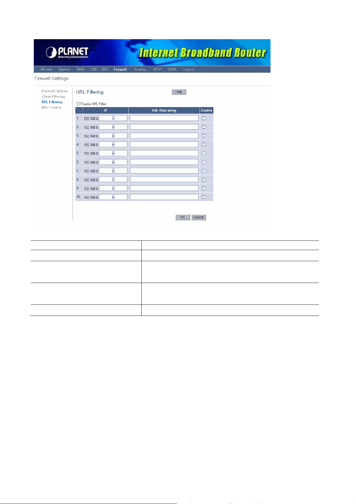
address or just keyword of the Web site.
Parameter Description
Enable URL Blocking
IP
URL filter string
Enable
Enable/disable URL Blocking
Enter the IP address range that you wish to apply this
rule.
You can enter the full URL address or the keyword of
the web site you want to block.
To enable the rule of URL Filtering.
3.5.4 MAC Control
You can filter Internet access for local clients based on MAC Address.
48
Page 49

Parameters Description
MAC Address Control
Check “Enabled” to enable MAC Filtering.
Configure MAC Address
Select Filter out or only accept the following MAC
address connects to Internet.
Fill in or “MAC Address” and “Comment” of the PC, or
select the MAC Address from “Action”, and then click
“Add”.
3.6 Routing
This section allows you to configure XRT-401E’s static route and check the current routing
table. The routing is only for internal routing using, so you do not need to disable NAT
function, and there are two ways to manage the device’s routing information, it includes RIP
and Static.
3.6.1 Routing Table
The routing table display the current routing information in system.
49
Page 50
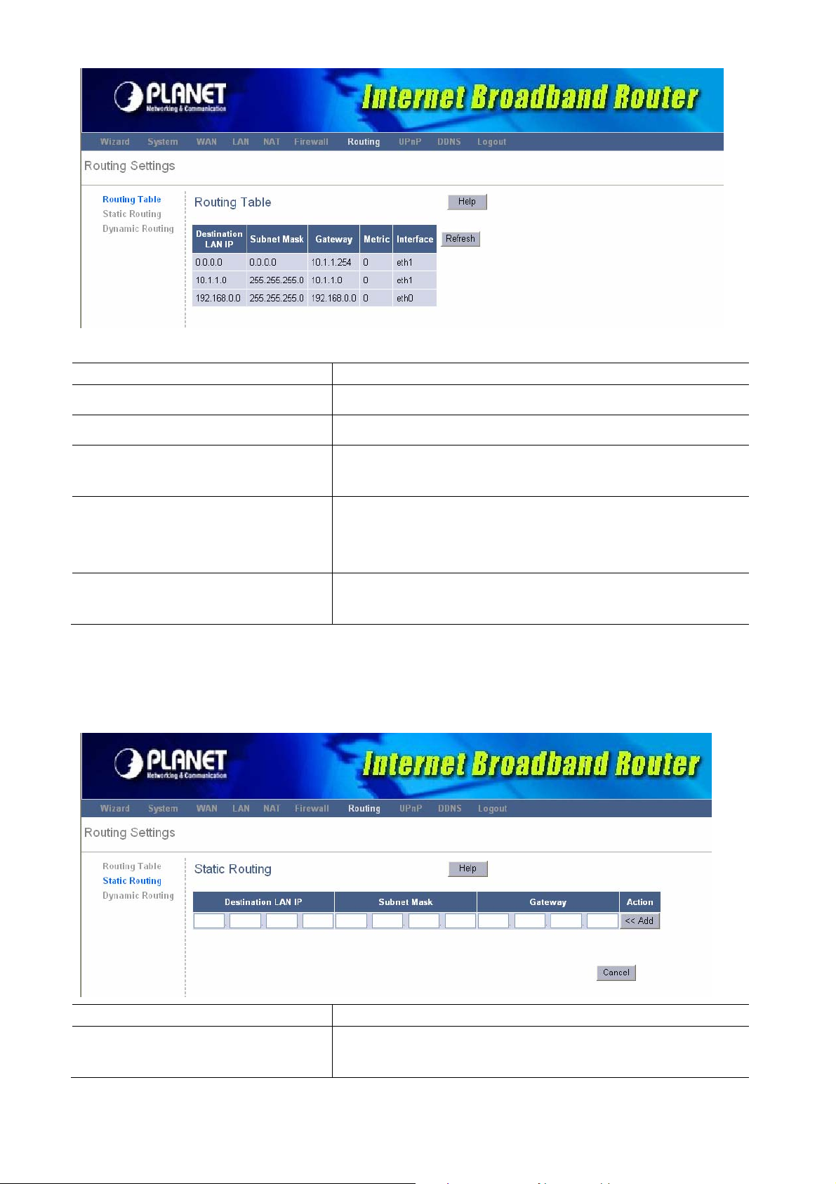
Parameter Description
Destination LAN IP
The IP address where packets will go to.
Subnet Mask
Gateway
Metric
Interface
The subnet mask of the destination IP address.
The gateway that the packets will pass by during
transmission.
Metric represents the “cost” of transmission for routing
purposes. IP Routing uses hop count as the
measurement of cost.
The interface that the packets pass through on the
device.
3.6.2 Static Routing
This page is used to configure the routing information. Here you can add / delete IP routes.
Parameter Description
Destination LAN IP, Subnet
Mask
Specify the destination LAN IP where the packets will
be routing to packets will be routing to.
50
Page 51

Gateway
Specify the other gateway IP that will route the
packets to the destination.
Add
Click “Add” to add this routing information.
3.6.3 Dynamic Routing
Dynamic Routing can be used to cache routes learned by routing protocols, thus allowing
the automation of static routing maintenance. The router, using the RIP (Routing
Information Protocol) protocol, determines the network packet's route based on the fewest
number of hops between the source and the destination. In this case, you could
automatically adjust to physical changes in the network layout.
Parameter Description
Working Mome
Listen Mode
Supply Mode
Specify your XRT-401E work as Router or Gateway.
Select the RIP version, and to start or stop RIP based
on the Global RIP mode selected.
This parameter determines if the XRT-401E includes
the router to this remote node in its RIP broadcasts or
RIP Multicast. Select the Mode you want to use.
3.7 UPnP
3.7.1 UPnP
With UPnP, all PCs in you Intranet will discover this router automatically. So you do not
have to do any configuration for your PC and can access the Internet through this router
easily.
51
Page 52
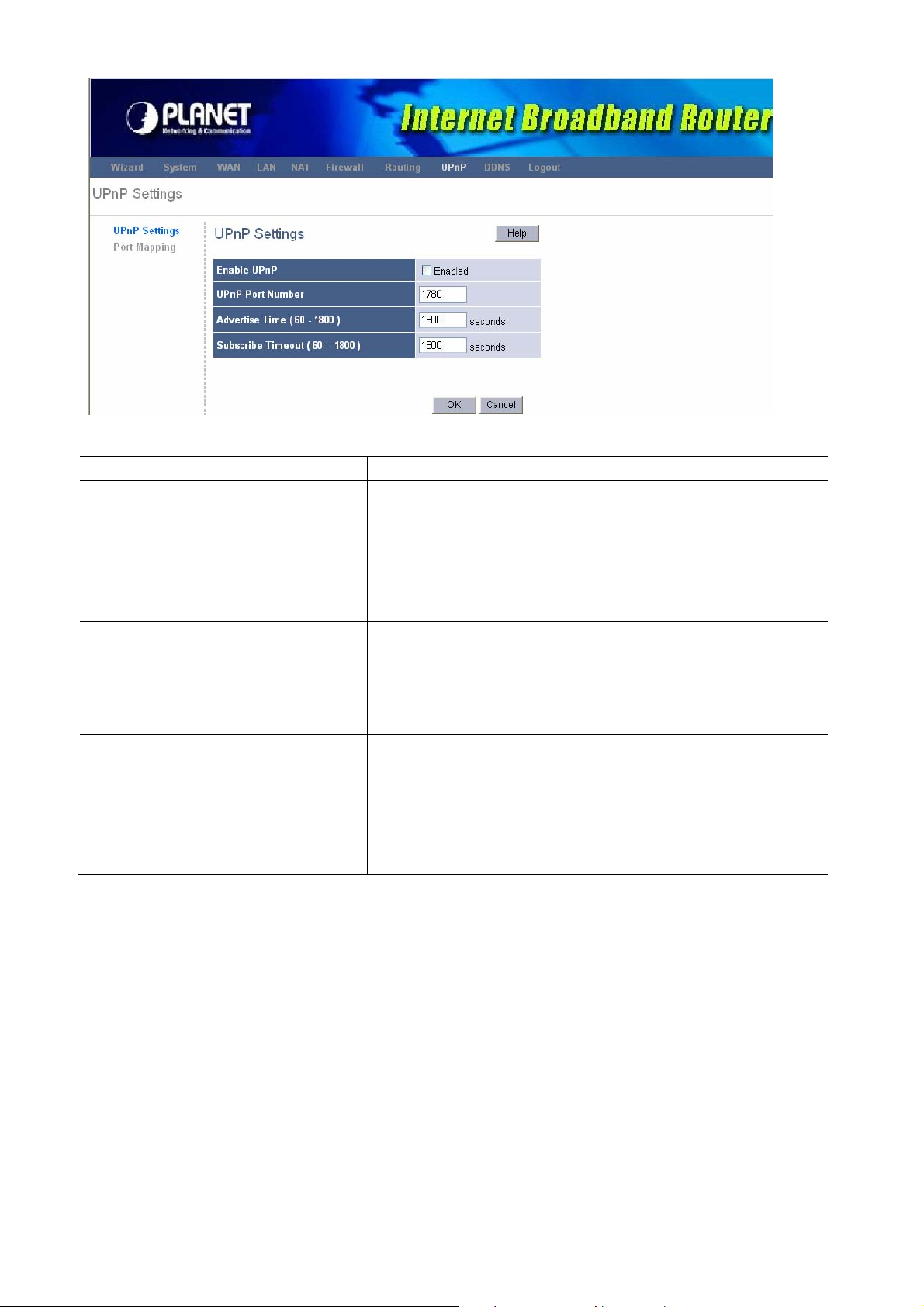
Parameter Description
Enable UPnP
After you enable the UPnP feature, all client systems
that support UPnP, like Windows XP can discover this
router automatically and access the Internet through
this router without any configuration.
UPnP Port Number
Advertise Time (60 ~ 1800)
Subscribe Timeout (60 ~ 1800)
Specify the port number for UPnP service using.
When UPnP service is working, router will broadcast a
message to LAN that the specific port number has
been used in a period of time. The maximum timing is
up to 1800 seconds.
When client stops responding UPnP service for a
period of time, router will break down the UPnP
connection automatically and UPnP service will be in
standby mode. The maximum time is up to 1800
seconds.
3.7.2 Port Mapping
The table display the current UPnP Port Mapping information in system.
52
Page 53

Parameter Description
Remote Host
It shows the IP address of the remote Host.
External Port
Internal Port, Internal Client
Protocol
Duration
Description
It shows the external port number
It shows the internal port number and clinet.
It shows the protocol.
It shows the duration time.
It describes this setting.
3.8 DDNS
DDNS allows you to map the static domain name to a dynamic IP address. You must get an
account, password and your static domain name from the DDNS service providers.
53
Page 54

Parameters Description
Enable/Disable
Enable/Disable the DDNS function of this router
Host Name
DDNS Server
User Name
Password
DDNS Retry Time
Your static domain name that use DDNS.
Select a DDNS service provider.
The account that your DDNS service provider
assigned to you.
The password you set for the DDNS service account
above.
To set up the time schedule to refresh DDNS setting.
Appendix A
How to Manually find your PC’s IP and MAC address
1) In Window’s open the Command Prompt program
2) Type ipconfig /all and <enter>
54
Page 55

• Your PC’s IP address is the one entitled IP address (192.168.0.7)
• The router’s IP address is the one entitled Default Gateway (192.168.0.1)
• Your PC’s MAC Address is the one entitled Physical Address (00-48-54-12-41-44)
Glossary
Default Gateway (Router): Every non-router IP device needs to configure a default
gateway’s IP address. When the device sends out an IP packet, if the destination is not on
the same network, the device has to send the packet to its default gateway, which will then
send it out towards the destination.
DHCP: Dynamic Host Configuration Protocol. This protocol automatically gives every
computer on your home network an IP address.
DNS Server IP Address: DNS stands for Domain Name System, which allows Internet
servers to have a domain name (such as www.Broadbandrouter.com) and one or more IP
addresses (such as 192.34.45.8). A DNS server keeps a database of Internet servers and
their respective domain names and IP addresses, so that when a domain name is
requested (as in typing "www.planet.com.tw" into your Internet browser), the user is sent to
the proper IP address. The DNS server IP address used by the computers on your home
network is the location of the DNS server your ISP has assigned to you.
DSL Modem: DSL stands for Digital Subscriber Line. A DSL modem uses your existing
phone lines to transmit data at high speeds.
Ethernet: A standard for computer networks. Ethernet networks are connected by special
cables and hubs, and move data around at up to 10/100 million bits per second (Mbps).
Idle Timeout: Idle Timeout is designed so that after there is no traffic to the Internet for a
preconfigured amount of time, the connection will automatically be disconnected.
IP Address and Network (Subnet) Mask: IP stands for Internet Protocol. An IP address
consists of a series of four numbers separated by periods, that identifies a single, unique
Internet computer host in an IP network. Example: 192.168.0.1. It consists of 2 portions: the
IP network address, and the host identifier.
The IP address is a 32-bit binary pattern, which can be represented as four cascaded
decimal numbers separated by “ aaa.aaa.aaa.aaa”, where each “aaa” can be anything from
000 to 255, or as four cascaded binary numbers separated by
“bbbbbbbb.bbbbbbbb.bbbbbbbb.bbbbbbbb”, where each “b” can either be 0 or 1.
55
Page 56

A network mask is also a 32-bit binary pattern, and consists of consecutive leading
1’s followed by consecutive trailing 0’s, such as 11111111.11111111.11111111.00000000.
Therefore sometimes a network mask can also be described simply as “x” number of
leading 1’s.
When both are represented side by side in their binary forms, all bits in the IP address that
correspond to 1’s in the network mask become part of the IP network address, and the
remaining bits correspond to the host ID.
For example, if the IP address for a device is, in its binary form,11011001.10110000.
10010000.00000111, and if its network mask is, 11111111.11111111.11110000.00000000
It means the device’s network address is 11011001.10110000.10010000.00000000, and
its host ID is, 00000000.00000000.00000000.00000111. This is a convenient and efficient
method for routers to route IP packets to their destination.
ISP Gateway Address: (see ISP for definition). The ISP Gateway Address is an IP
address forthe Internet router located at the ISP's office.
ISP: Internet Service Provider. An ISP is a business that provides connectivity to the
Internet for individuals and other businesses or organizations.
LAN: Local Area Network. A LAN is a group of computers and devices connected together
in a relatively small area (such as a house or an office). Your home network is considered a
LAN.
MAC Address: MAC stands for Media Access Control. A MAC address is the hardware
address of a device connected to a network. The MAC address is a unique identifier for a
device with an Ethernet interface. It is comprised of two parts: 3 bytes of data that
corresponds to the Manufacturer ID (unique for each manufacturer), plus 3 bytes that are
often used as the product’s serial number.
NAT: Network Address Translation. This process allows all of the computers on your home
network to use one IP address. Using XRT-401E’s NAT capability, you can access the
Internet from any computer on your home network without having to purchase more IP
addresses from your ISP.
Port: Network Clients (LAN PC) uses port numbers to distinguish one network
application/protocol over another. Below is a list of common applications and protocol/port
numbers:
56
Page 57

PPPoE: Point-to-Point Protocol over Ethernet. Point-to-Point Protocol is a secure data
transmission method originally created for dial-up connections; PPPoE is for Ethernet
connections. PPPoE relies on two widely accepted standards, Ethernet and the
Point-to-Point Protocol. It is a communications protocol for transmitting information over
Ethernet between different manufacturers
Protocol: A protocol is a set of rules for interaction agreed upon between multiple parties
so that when they interface with each other based on such a protocol, the interpretation of
their behavior is well defined and can be made objectively, without confusion or
misunderstanding.
Router: A router is an intelligent network device that forwards packets between different
networks based on network layer address information such as IP addresses.
Subnet Mask: A subnet mask, which may be a part of the TCP/IP information provided by
your ISP, is a set of four numbers (e.g. 255.255.255.0) configured like an IP address. It is
used to create IP address numbers used only within a particular network (as opposed to
valid IP address numbers recognized by the Internet, which must be assigned by InterNIC).
TCP/IP, UDP: Transmission Control Protocol/Internet Protocol (TCP/IP) and Unreliable
Datagram Protocol (UDP). TCP/IP is the standard protocol for data transmission over the
Internet. Both TCP and UDP are transport layer protocol. TCP performs proper error
detection and error recovery, and thus is reliable. UDP on the other hand is not reliable.
They both run on top of the IP (Internet Protocol), a network layer protocol.
WAN: Wide Area Network. A network that connects computers located in geographically
separate areas (e.g. different buildings, cities, countries). The Internet is a wide area
network.
Web-based management Graphical User Interface (GUI): Many devices support a
graphicaluser interface that is based on the web browser. This means the user can use the
familiar Netscape or Microsoft Internet Explorer to Control/configure or monitor the device
57
Page 58

being managed.
58
Page 59

EC Declaration of Conformity
For the following equipment:
*Type of Product: Internet Broadband Router
*Model Number: XRT-401E
* Produced by:
Manufacturer‘s Name : PLANET Technology Corp.
Manufacturer‘s Address : 11F, No 96, Min Chuan Road
Hsin Tien, Taipei, Taiwan, R.O.C.
is herewith confirmed to comply with the requirements set out in the Council Directive on the
Approximation of the Laws of the Member States relating to Electromagnetic Compatibility
Directive on (89/336/EEC).
For the evaluation regarding the EMC, the following standards were applied:
Conducted / Radiated EN 55022 (1998 Class A)
Harmonic EN 61000-3-2 (2000)
Flicker EN 61000-3-3 (1995)
Immunity EN 55024 (1998)
ESD EN 61000-4-2 (1995)
RS EN 61000-4-3 (1995)
EFT/ Burst EN 61000-4-4 (1995)
Surge EN 61000-4-5 (1995)
CS EN 61000-4-6 (1996)
Magnetic Field EN 61000-4-8 (1993)
Voltage Disp EN 61000-4-11 (1994)
Responsible for marking this declarati o n i f the:
⌧ Manufacturer Authorized representative established within the EU
Authorized representative established within the EU (if applicable):
Company Name: Planet Technology Corp.
Company Address: 11F, No.96, Min Chuan Road, Hsin Tien, Taipei, Taiwan, R.O.C
Person responsible for making this declaration
Name, Surname Allen Huang
Position / Title : Product Manager
Taiwan
18th Feb., 2008
Place Date Legal Singnature
PLANET TECHNOLOGY CORPORATION
e-mail: sales@planet.com.tw http://www.planet.com.tw
11F, No. 96, Min Chuan Road, Hsin Tien, Taipei, Taiwan, R.O.C. Tel:886-2-2219-9518 Fax:886-2-2219-9528
 Loading...