

Page 1
1. Overview
Thank you for purchasing PLANET 150-watt DC -48V power
supply.
Power Supply Unit Input Range
XGS3-PWR150-48 -40 to -60V DC
-40
-
4.7 -2.8A
-60V
Open the box of the Redundant Power Supply unit and
carefully unpack it. The box should contain the following
items:
The -48V DC Power Supply unit x 1
User’s Manual x 1
If any item is found missing or damaged, please contact
your local reseller for replacement.
2. Introduction
Before installation, please be sure to read this user’s
manual carefully to complete machine installation. This
manual shows how to quickly install the power from the
XGS3-24042, unless specied as “redundant power” that
will be used for these four models.
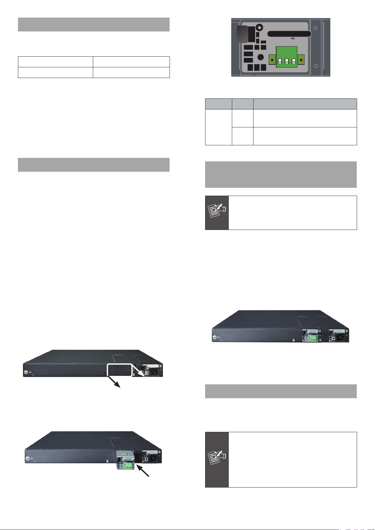
The following gure illustrates the front panel of the
XGS3-PWR150-48.
– 1 – – 2 –
Figure 2-1 XGS3-PWR150-48 Front View
LED Color Function
Green
LNK/ACT
Red
Lights to indicate DC power input has
power.
Blinks to indicate DC power input has
failed or warning.
3. Installing Redundant Power Supply
Unit
The XGS3-PWR150-48 is hot-swappable during
operation; there is no need to power off the
Note
Switch before sliding or removing the module.
Follow these steps to install the redundant power into the
Switch:
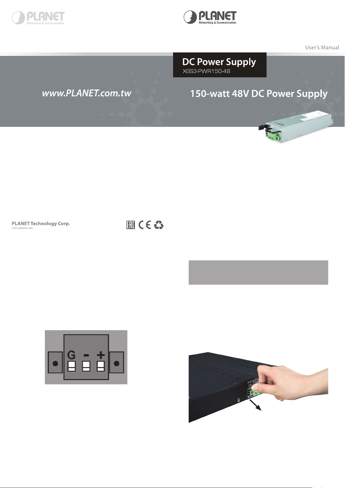
1. Place the Switch on a at surface. Grasp the thumbscrew
on the sides of the blank bracket and turn counter-clockwise to unscrew them. You can also use a screwdriver
to remove the blank bracket. Do not discard the blank
bracket. Put the blank bracket back if you remove the
module out of the Switch.
Figure 3-1 Removing the blank bracket
2. Install the redundant power by inserting it into the rails
and sliding it.
Figure 3-2 Inserting the XGS3-PWR150-48
3. Hear the redundant power snap in place to nish insertion.
Figure 3-3 Inserting the XGS3-PWR150-48
4. Wiring the DC Power Input
The 3-pin terminal block connector on the redundant power
uses DC power input. Please follow the steps below to
insert the power wire.
1. Before connecting the DC power wires, please
check whether your local DC power source is
stable.
Note
2. The wire gauge for the power cable should be in
the range of 12 ~ 24 AWG.
3. The DC power input range is -40 ~ -60V DC.
– 3 – – 4 –
Page 2
1. Insert the positive DC power wire into the positive(+)
contact (right pin) and tighten the wire-clamp for
preventing the DC power wire from loosening.
2. Insert the negative DC power wire into the negative(-)
contact (middle pin) and tighten the wire-clamp for
preventing the DC power wire from loosening.
3. Insert the grounding power wire into the grounding(G)
contact (left pin) and tighten the wire-clamp for
preventing the power wire from loosening.
5. Removing Redundant Power
Supply Unit
Follow these steps to install the redundant power into the
Switch:
1. Remove all DC power wires from terminal block of the
XGS3-PWR150-48.
2. To remove the redundant power from the XGS3-24042,
move the lever to the right and pull it out.
Figure 4-1 Power pin design of XGS3-PWR150-48
– 5 – – 6 –
Figure 5-1 Removing the XGS3-PWR150-48
 Loading...