

Planet WSW-2620 User Manual

Web Switch
WSW-2620
Web/SNMP Manageable Switch

Trademarks
Copyright PLANET Technology Corp. 1999.
Contents subject to revision without prior notice.
PLANET is a registered trademark of PLANET Technology Corp.
All other trademarks belong to their respective owners.
FCC Warning
This device has been tested and found to comply with limits for a Class A
digital device, pursuant to Part 15 of the FCC Rules. These limits are
designed to provide reasonable protection against harmful interference when
the equipment is operated in a commercial environment. This equipment
generates, uses and can radiate radio frequency energy and, if not installed
and used in accordance with the user’s manual, may cause interference in
which case user will be required to correct the interference at his own
expense.
CE Mark Warning
This is a Class A product. In a domestic environment, this product may
cause radio interference in which case the user may be required to take
adequate measures.
REVISION
PLANET Web Switch Series User’s Guide for model
WSW-2620
Revision 1.0 (April 1999)
Part No.: EM-WSW26v1

Table of Contents
Chapter 1 Introduction.............................................................1-1
About Web Switch WSW-2620...................................1-1
Key Features................................................1-1
Front Panel.................................................1-3
Ports.......................................................1-4
10BASE-T ports.......................................................................1-4
10BASE-T/100BASE-TX port..................................................1-4
Mini-Console................................................1-4
Console Keys................................................1-5
Rear Panel..................................................1-5
Chapter 2 Installation and Setup............................................2-1
Rack Mounting...............................................2-1
Connecting a Terminal to the Console Port ...................2-2
100BASE-TX Connections......................................2-3
Connecting Workstations.....................................2-4
Connecting to Other Ethernet Hubs ...........................2-4
Chapter 3 Mini-Console ..........................................................3-1
Message Zone................................................3-2
Observing Basic Port Information ............................3-2
Port Group Indicators....................................................................3-3
Port Indicators..............................................................................3-4
Port Indicator Definitions..............................................................3-4
Bar Gauge ....................................................................................3-5
Unit ID.........................................................................................3-5
Lock.............................................................................................3-5
Console Keys................................................3-6
Port Group Selection........................................3-7
Menu Tree...................................................3-8
Utilization ....................................................................................3-8
Collision.......................................................................................3-8
Group Selection............................................................................3-9

Statistics.......................................................................................3-9
Port Status..................................................................................3-10
Port Configuration......................................................................3-11
Unit Configuration......................................................................3-12
Observing Utilization......................................3-13
Observing Collision Level..................................3-14
Monitoring Ports Status....................................3-14
Monitoring Port Statistics .................................3-15
Configuring Ports..........................................3-15
Lock the Mini-Console......................................3-15
Unlock the Mini-Console....................................3-16
Secure Your Switch.........................................3-18
Set Password ..............................................................................3-18
In Case You Forget the Mini-Console Password..........................3-19
Restart the Switch.........................................3-19
Chapter 4 Setting-Up for Management...................................4-1
Managing The Switch.........................................4-1
Console Program.............................................4-1
Terminal Program.....................................................................4-2
Navigating the Console Program Screens ......................4-7
Booting the Switch for the first time .......................4-8
Login Screen ................................................................................4-9
Main Menu.................................................................................4-10
System Download.......................................................................4-11
Network Configuration...............................................................4-12
Chapter 5 Console Management............................................5-1
Using a Telnet Session......................................5-1
Console Management Command Overview .........................5-2
Configuring the System......................................5-3
Main Menu...................................................................................5-4
System Information ......................................................................5-4
Management Setup.......................................................................5-6
Network Configuration .............................................................5-7
Management Port Configuration ...............................................5-8
SNMP Community Setup..........................................................5-9
Trap Receiver Menu ...............................................................5-10
Management Capability Setup.................................................5-12
Trap Filter Setup.........................................................................5-13

Device Control ...........................................................................5-14
Switch Control/Status .............................................................5-16
Switch Port Control/Status......................................................5-17
Static Address Configuration...................................................5-20
Static Unicast Address Configuration Menu.........................5-21
Static Group Address Configuration....................................5-23
Static Group Address Forward Unregister Configuration .....5-25
VLAN Control........................................................................5-26
VLAN Configuration Menu.................................................5-27
GVRP Configuration...........................................................5-30
GVRP Port Configuration ...................................................5-32
Spanning Tree Protocol Group Configuration..........................5-33
Spanning Tree Protocol Port Configuration .............................5-35
Trunk Group Configuration.....................................................5-37
User Authentication....................................................................5-37
System Utility.............................................................................5-39
System Download...................................................................5-40
System Restart........................................................................5-43
Factory Reset..........................................................................5-44
Download Port Setting............................................................5-45
Login Timeout Interval...........................................................5-46
Configuration Upload Setting..................................................5-47
Configuration Upload Request/Status......................................5-48
Ping To Another Host .............................................................5-49
Appendix A Product Specifications.......................................A-1

Introduction 1-1
WSW-2620 User’s Guide
Chapter 1
Introduction
About Switch WSW-2620
Switch WSW-2620 is an innovative new design in network switching, with
many features that make monitoring, configuring and expanding a network,
better and easier than ever before.
Key Features
w Smart Mini-Console Operation
The Mini-Console (Vacuum Florescent Display) is a major new
technological breakthrough, a brilliant display panel that provides
text and graphics information and extensive management capability
for the user.
w Web-Based Management
Built in Web-Based management enables management from a web
browser allowing management from any remote location.
w SNMP Network Management
SNMP functionality has been built in providing comprehensive
management capabilities for HP OpenView and other network
management platforms.
w VLANs (Virtual LANs)
VLAN capability provides up to 31 LANs within the Switch. The
GVRP function allows you to designate dynamic VLANs.
1-2 Introduction
Non Printing
w Ports
• 24 10BASE-T (RJ-45) ports
• 1 10BASE-T/100BASE-TX auto-sensing port (RJ-45)
• 1 MDI-II Uplink port (RJ-45) shared with port 1
• 2 expansion slots allow you to add 10BASE-T/100BASE-
TX or 100BASE-FX ports
• 1 EIA-232 port
w Expansion Slot
Switch WSW-2620 provides two expansion slots for the addition of
2 10BASE-T/100BASE-TX MDI-II or MDI-X ports or 1 100BASEFX port.
w Optional Modules
The following two types of expansion modules are available for this
system.
Note: The power must be turned off before inserting or
removing Modules.
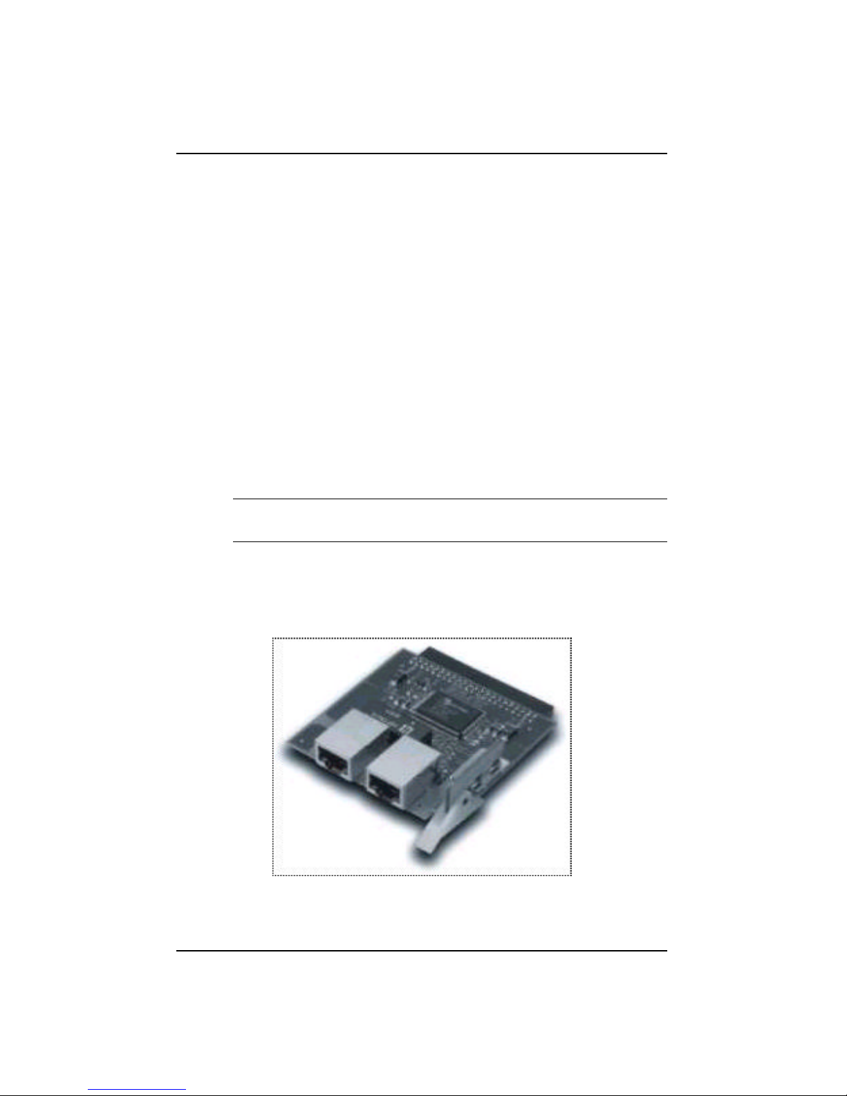
• Module WSW-BTX
This 10BASE-T/100BASE-TX module with two RJ-45
connectors is configured for either MDI-II or MDI-X.
Figure 1.1 Module WSW-BTX
Introduction 1-3
WSW-2620 User’s Guide
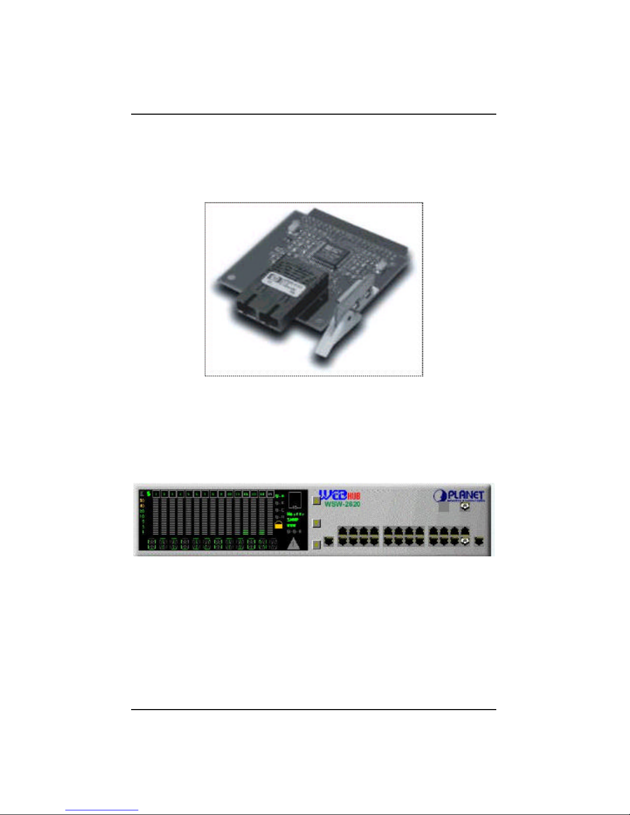
• Module WSW-BSC
This 100BASE-FX module is for use with fiber optics
cable with one SC type connector.
Figure 1.2 Module WSW-BSC
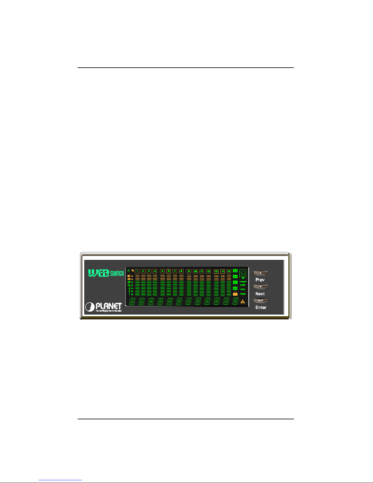
Front Panel
The front panel consists of the Mini-Console, the Console Keys and Ethernet
ports.
Figure 1.3 Front Panel
1-4 Introduction
Non Printing
Ports
10BASE-T ports
The front panel supports 24 10Mbps ports (ports 1 through 24) and 1 MDI-II
port shared with Port 1.
10BASE-T/100BASE-TX port
Also located on the right side of the front panel, Port 25 is a 10/100Mbps
auto-sensing port. This port is one way the WSW-2620 can connect to Fast
Ethernet devices with RJ-45 plugs.
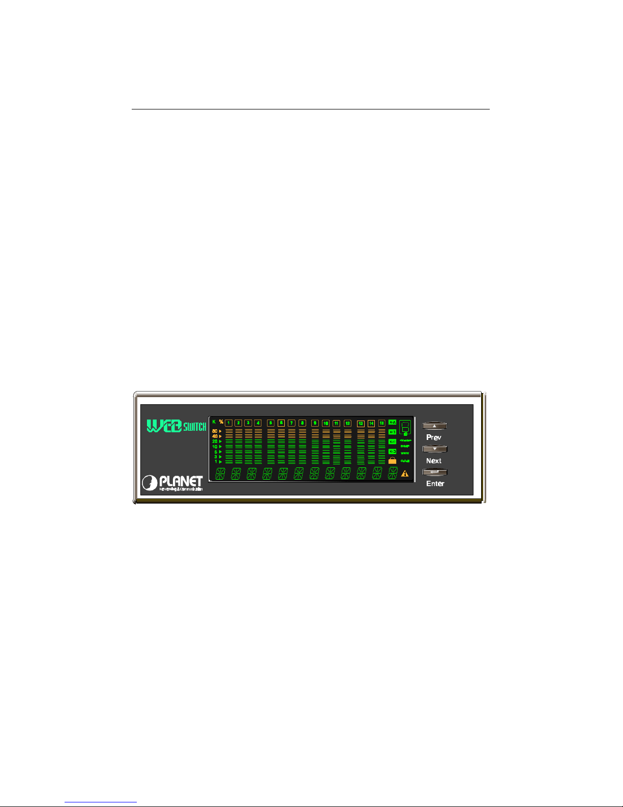
Mini-Console
The Mini-Console actively displays the network status information. Together
with the build-in Console Keys, users are able to monitor and configure all
the ports simultaneously or individually.
WSW-2620
Figure 1.4 Mini-Console
Introduction 1-5
WSW-2620 User’s Guide
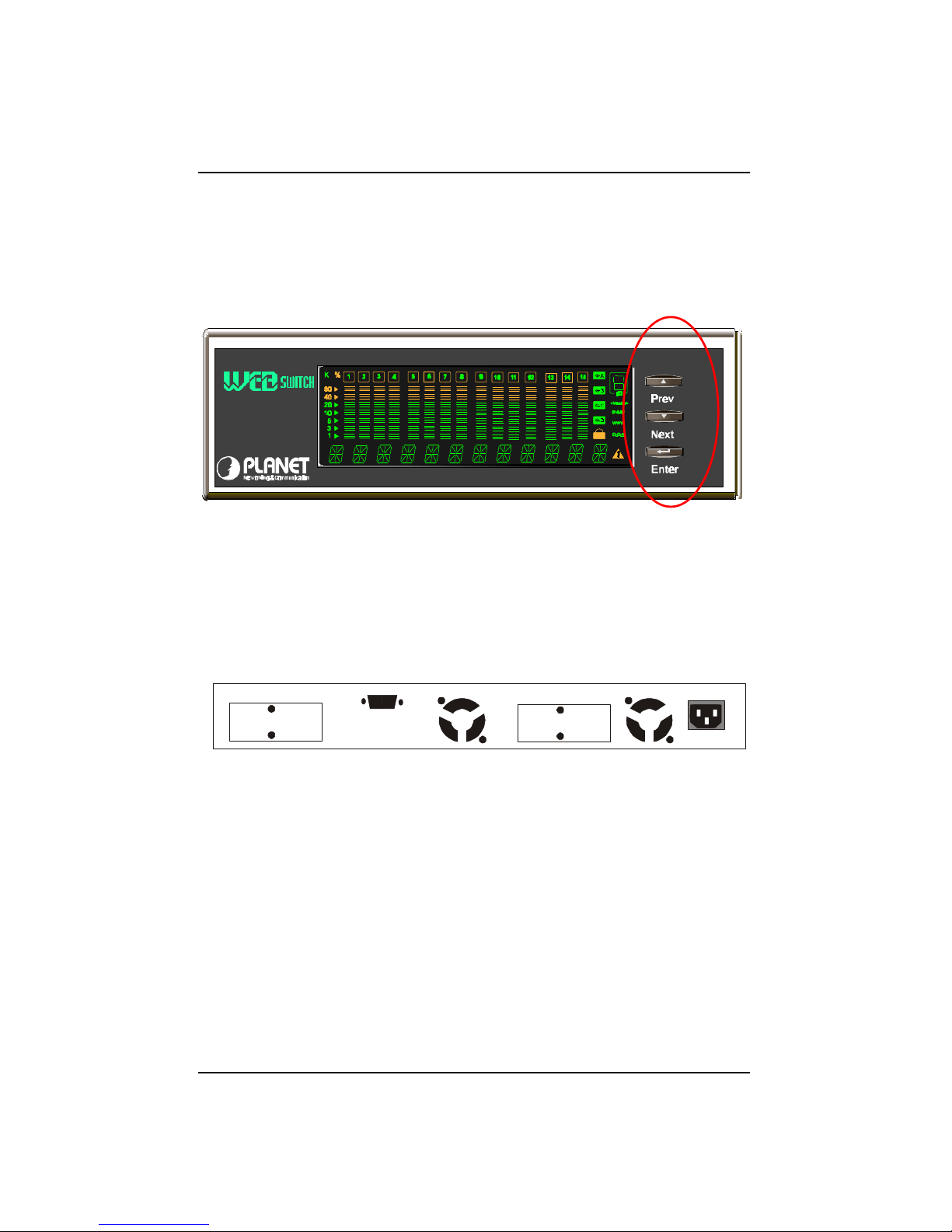
Console Keys
The Console Keys are used to cycle through the menu tree, make selections
and configure settings.
WSW-2620
Figure 1.5 Console Keys
Rear Panel
Ports 26 and 27 are located on the rear panel and accept slide-in modules for
high-speed data transfer. Module WSW-BTX or Module WSW-BSC can be
added to meet the requirement of complex network environments.
Figure 1.6 Rear Panel
Installation and Setup____________________________________ 2-1
WSW-2620 User’s Guide
Chapter 2
Installation and Setup
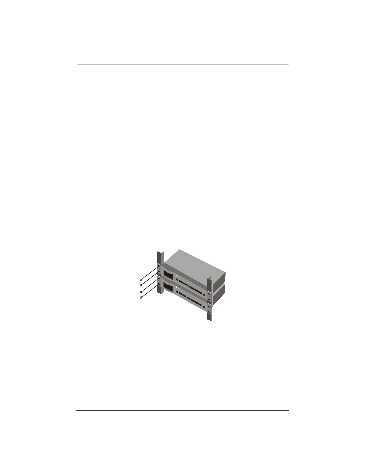
Rack Mounting
Switch WSW-2620 is 1.25U high and fits into standard 19-inch racks. Put
the mounting brackets over the mounting holes on the sides of unit. Insert
screws and fully tighten with suitable screwdriver. Then insert the device
into the 19-inch rack. Please make sure that the ventilation holes are not be
obstructed.
Figure 2.1 Rack Mounting
2-2 Installation and Setup
WSW-2620 User’s Guide
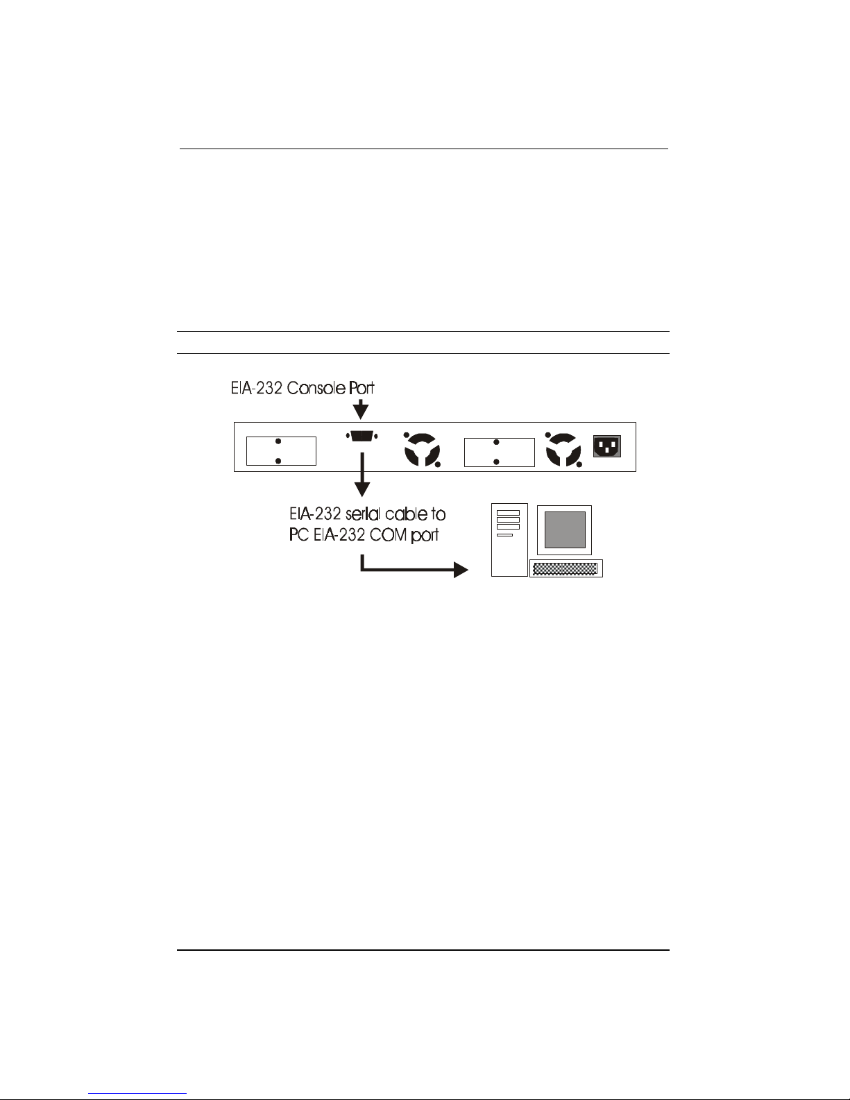
Connecting a Terminal to the Console
Port
Connect an EIA-232 serial cable to a COM port on a PC or notebook
computer and to the Console Port of the Switch WSW-2620 as show below.
Note: Do not use a null modem cable.
Figure 2.2 Connecting a PC via Console Port.
Installation and Setup____________________________________ 2-3
WSW-2620 User’s Guide
100BASE-TX Connections
Switch WSW-2620 provides 100BASE-TX connections at port 25 through
UTP cables with RJ-45 plugs as well as through the optional slide-in
modules.
Figure 2.3 100BASE-TX Connections
2-4 Installation and Setup
WSW-2620 User’s Guide
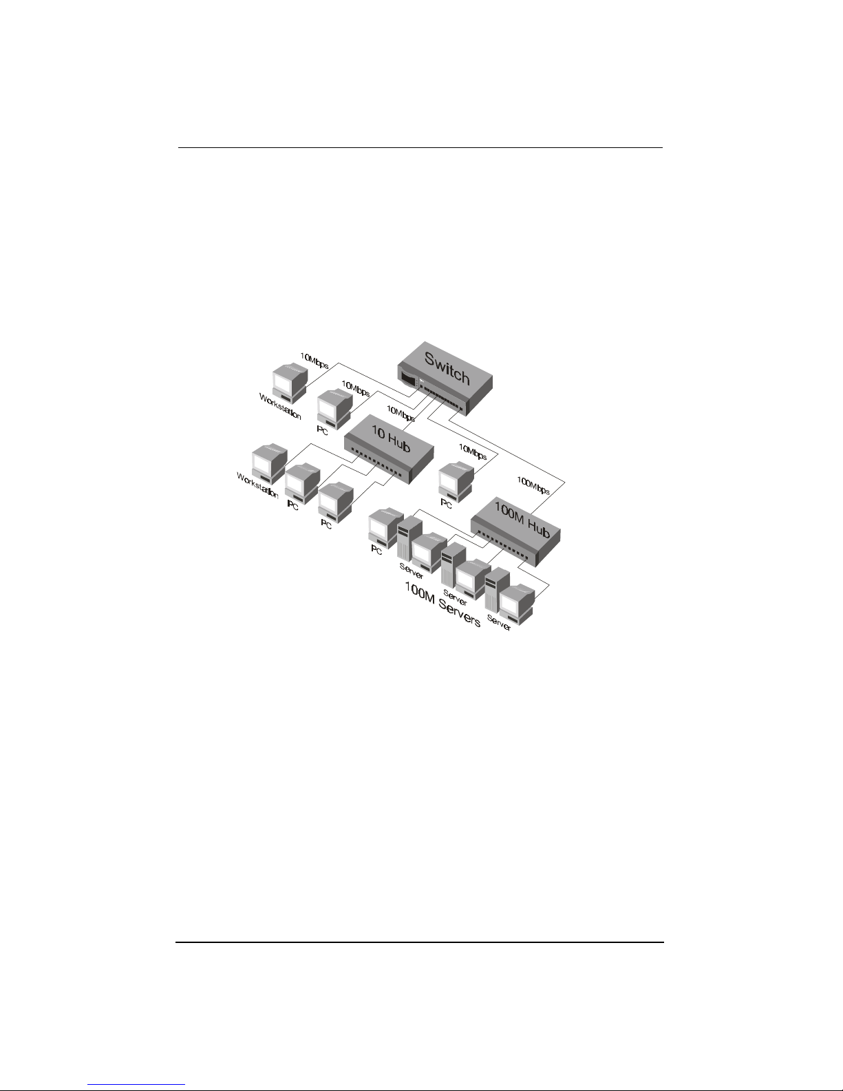
Connecting Workstations
Figure 2.4 shows Switch WSW-2620 as a desktop switch in a client server
mode.
Figure 2.4 Connecting Workstations.
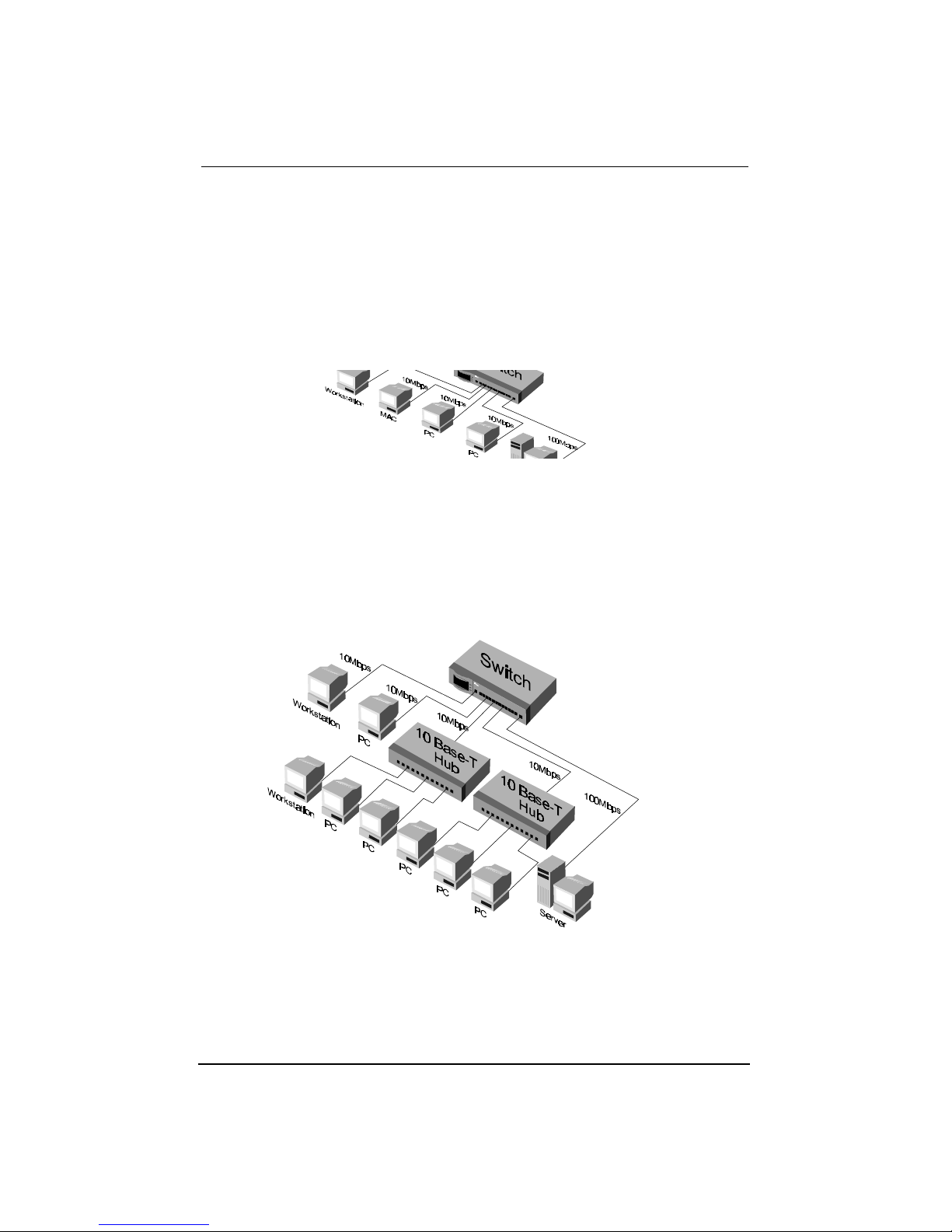
Connecting to Other Ethernet Hubs
10BASE-T hubs can be connected to ports 1~24 as shown in Figure 2.5.
Figure 2.5 Connecting to other Ethernet hubs
Mini-Console 3-1
WSW-2620 User Guide
Chapter 3
Mini-Console
The Mini-Console is a high definition vacuum florescent display panel that
provides brilliant text and graphics. It continuously displays information
about the ports status. Configuration settings can be viewed or changed when
used in combination with the Console Keys.
WSW-2620
Figure 3.1 Mini-Console
3-2 Mini-Console
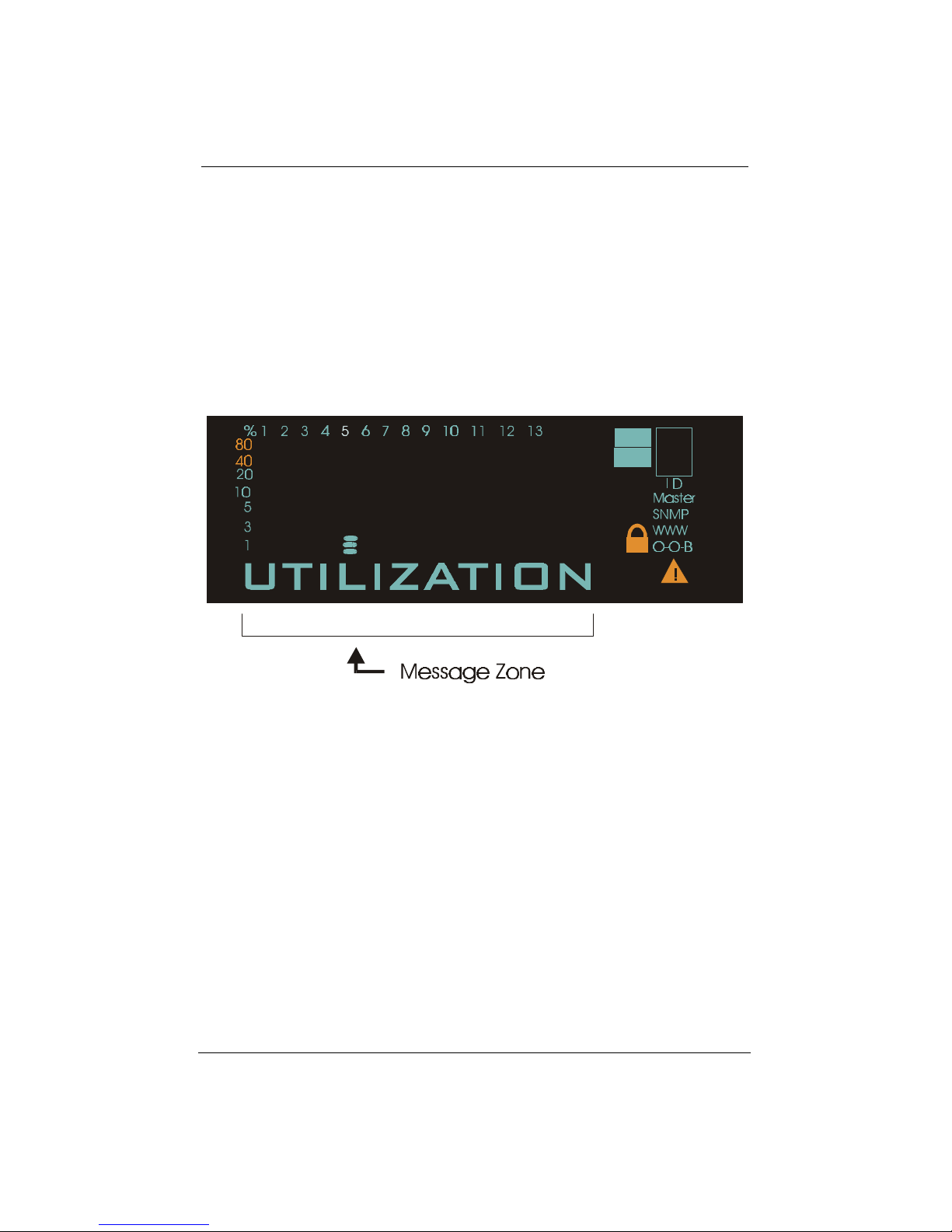
Message Zone
The Message Zone displays the menu items of the menu tree. The large
alphanumeric characters are easy to read and are an important navigational
tool.
G-A
G-B
Figure 3.2 Message Zone
Observing Basic Port
Information
The basic port information, such as link up, link down, transmit/receive
activity, enabled/disabled as well as auto partition can be easily spotted
through the Port Indicators located in the first row of the Mini-Console.
Mini-Console 3-3
WSW-2620 User Guide
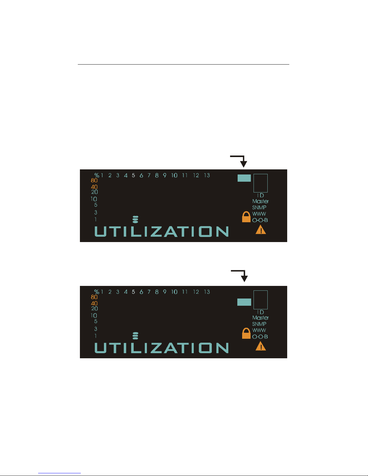
Port Group Indicators
On the right-hand side of the Message Zone, there are two port group
indicators, G-A and G-B. When the G-A icon is illuminated, port indicators 1
through 13 represent ports 1 through 13. When the G-B icon is illuminated,
port indicators 1 through 14 represent ports 14 through 27.
G-A
Port Group G-A Indicator
Figure 3.3 Port Group G-A, Representing Ports 1 Through 13
G-B
Port Group G-B Indicator
Figure 3.4 Port Group G-B, Representing Ports 14 Through 27

3-4 Mini-Console
Port Indicators
The Port Indicators show the ports that are linked up by intensifying the light
for the ports that are available. While the ports are receiving or transmitting
data, the port’s number will be flashing.
Port Indicators show the ports that are not linked as slightly on or dimmed.
An amber rectangular frame appears around the port number of ports that are
disabled through the Mini-Console or other management programs. If the
amber rectangular frame is blinking, it means it has been partitioned
automatically due to some error condition such as a loop or broadcast storm
that has been detected.
Figure 3.5 Port Indicators
Port Indicator Definitions
The port indicators define the ports status and activity by the way they are
illuminated, such as ON, OFF, blinking, flashing and a frame around the
numbers.
The following table summarizes the definition of the port indicators.
Port Indicator Definitions
Port No. Frame Indicates
Slightly on Off Port is available but link is down.
On Off Port is available and link is up.
Flashing Off Link is up and transmitting/receiving data.
On On The port is disabled by the administrator.
On Blinking The port is partitioned by machine itself due to
errors.
Table 3.1 Port Indicator Definitions

Mini-Console 3-5
WSW-2620 User Guide
Bar Gauge
There are Bar Gauges below every port indicator that ascend/descend
indicating an approximate percentage of usage relevant to the menu item in
the message zone. As the bar gauge rise the relevant percentage can
measured against the percentage scale.
Figure 3.6 Bar Gauge
Unit ID
A unique ID number in the ID frame identifies each switch in the stack. The
master switch assumes the ID number “1”. Additional managed switches
such as 10S will assume ID numbers based on the port that they are
connected to, plus one. For instance a 10S switch connected to port one will
assume the ID number “2”.
Lock
When the system is powered up, a lock icon appears below the ID number in
Mini-Console indicating the console is locked. Unlocking the console
removes the lock icon. See the section “Locking the Console” in this chapter
for more information.
3-6 Mini-Console
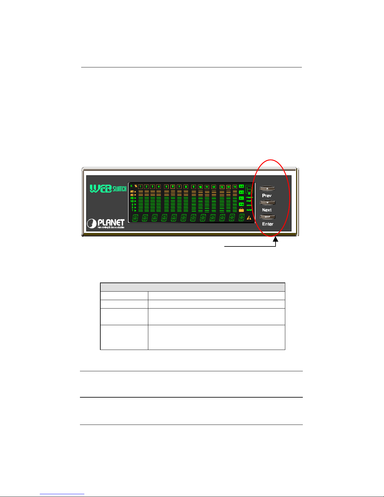
Console Keys
The Console Keys are used to cycle through the menu tree, to make
selections and settings. Pressing the Prev or Next Console Keys moves one
position in the menu. Do not hold the keys down in an effort to auto cycle
through the menus. Holding down keys is used to change default settings.
WSW-2620
The Console Keys
Figure 3.7 Console Keys
The following table summarizes the Console Keys functions.
Console Keys
Previous Key Cycles back through the menus.
Next Key Cycles forward through the menus.
Enter Key Select the displayed menu item or when
pressed and held changes a setting.
Enter Key
Hold Down
Holding down the Enter key changes the
default setting and places an “*” before the
item indicating it is the current default.
Table 3.2 Console Keys
Note: When the Message Zone is in Collision or Utilization mode, the
Enter key can be pressed to scroll between port group A and port
group B.

Mini-Console 3-7
WSW-2620 User Guide
Port Group Selection
The port group selection function allows you to monitor and configure all of
the ports available on the switch. Including expansion modules, there can be
a total of 27 ports available.
In both the UTILIZATION and COLLISION modes, you can select a port
group by pressing the Enter button. The corresponding port group indicator
will be illuminated.
To configure the default port group to be displayed, follow these steps:
1. Press the Prev or Next buttons to select GROUP SEL from the main
menu.
2. Press the Enter button.
3. Press the Prev or Next buttons to select the port group that you want to
be displayed as the default port group.
4. Press and hold the Enter button for 4 seconds. An asterisk will appear to
the left of the port group, indicating that it is the default port group to be
displayed.
5. Press the Prev or Next buttons to select MAIN MENU.
6. Press the Enter button to return to the main menu.

3-8 Mini-Console
Menu Tree
The menu tree consists of six main menu items, Utilization, Collision, Group
Selection, Statistics, Port Status, Port Configuration and Unit Configuration.
Utilization
The main menu item Utilization, displays utilization status for all linked ports
by the rising/falling gauge bars below the linked ports.
MAIN MENU
UTILIZATION
Actively displays the utilization for linked ports.
Table 3.3 Utilization
Collision
The main menu item Collision, displays collision status for all linked ports by
the rising/falling gauge bars below the linked ports.
MAIN MENU
COLLISION
Actively displays collision for linked ports.
Table 3.4 Collision

Mini-Console 3-9
WSW-2620 User Guide
Group Selection
The main menu item Group Selection allows you to select the default port
group that is displayed in the Message Zone. An asterisk indicates the default
port group. To select a default port group, press the Next/Prev key to cycle to
the desired group. When the desired port group is displayed, press and hold
the Enter key until an asterisk is displayed.
MAIN MENU
GROUP SEL
Select default port group display.
Table 3.5 Group Selection
Statistics
The main menu item Statistics has 16 sub menus, one for each port 1~27 and
one to return to the main menu. Press the Next/Prev key to cycle to a port and
then press the Enter key to view the different statistics available. Pressing the
Enter key again shows the count for the selected statistic.
Cycle to Back to select another statistic or cycle to MAIN MENU to exit to the
main menu.

3-10 Mini-Console
MAIN MENU
STATISTICS
Sub-Menu Statistic Count
PORT 1~27 RX-FRAMES
RX OCTETS
MULTICAST-RX
BROADCAST-RX
RX-ALIGN ERR
RX-CRC ERR
RX-JABBERS
RX-FRAGMENTS
OVERSIZE RX
UNDERSIZE RX
TX FRAMES
TX OCTETS
MULTICAST-TX
BROADCAST-TX
RX OVERUN
BACK
MAIN MENU
Press Enter
at any of the
Statistic to
view the
count for
that statistic
Table 3.6 Statistics
Port Status
The Port Status menu displays status information about each port
individually or all the ports simultaneously. When viewing individual ports
the status will automatically cycle through the current settings for the port.
When ALL PORTS is selected, use the Next/Prev key to cycle through the
settings. The gauge bars indicate the ports that are set to the particular setting
and the message zone displays the status setting for the ports.

Mini-Console 3-11
WSW-2620 User Guide
MAIN MENU
PORT STATUS
PORT 1~27 SHOW STATUS Auto cycles
through all
settings
ALL PORTS 10M PORTS
100M PORTS
HALF DUPLEX
FULL DUPLEX
ENABLED
DISABLED
STORE—FWD
BACK
MAIN MENU
Press the Enter
console key once
and then the
Prev/Next keys to
cycle through all
settings, the
gauge bars
indicate the ports
setting.
Table 3.7 Port Status
Port Configuration
The Port Configuration menu allows the configuring of ports 1~27 when the
console is unlocked. Table 3.6 lists typical default settings and the possible
optional settings. An “*” appears before each current setting. To change a
setting hold down the Enter key until an “*” appears before the setting, the
“*” is removed from the previous setting.
Note: Only ports 25, 26 and 27 can be configured to 100Mbps speed.
When the Console is locked, this menu cannot be entered. See “Unlocking
the Console” for information on unlocking the console.

3-12 Mini-Console
MAIN MENU
PORT CONFIG
Sub Menu Default Setting Options
PORT 1~27
ALL PORTS
MAIN MENU
*AUTO-NEGO FULL DUPLEX
HALF
DUPLEX
*ENABLE DISABLE
*BS ENABLE BS DISABLE
BACK
MAIN MENU
Table 3.8 Port Configuration
Unit Configuration
The Unit Configuration menu allows configuring the system and viewing the
current system information.
MAIN MENU
UNIT CONFIG
Sub-Menu Options
CONSOLE LOCK ENABLE
DISABLE/BACK
IP ADDRESS
SUBNET MASK
DEF GATEWAY (Default Gateway)
SLIP ADDR (Slip Address)
NETWORK CONF
BACK
SET PASSWORD
SYS RESTART Pressing Enter will restart the Switch

Mini-Console 3-13
WSW-2620 User Guide
SYS INFO Pressing Enter will scroll through
the Switch’s setting information.
Pressing any key will return you to
the SYS INFO menu.
MAIN MENU
Table 3.9 Unit Configuration
Observing Utilization
The network manager may want to see the traffic load for every segment and
try to balance the load. It is easy to do so with Switch WSW-2620 by
selecting the UTILIZATION item, the system startup default. While the item
is selected, the level of Utilization for the enabled ports goes up and down as
the traffic load varies.
The reference for the level of utilization is based on the speed of the port that
is running. For example, a port that is running in 10M half duplex, the 100%
stands for the bandwidth of 10M. The following table shows the relation for
each speed:
Observing Utilization
SPEED 100% Stands for:
10M half duplex 10M
10M full duplex 20M
100M half duplex 100M
100M full duplex 200M
Table 3.10 Port Speed

3-14 Mini-Console
Observing Collision Level
When “COLLISION” is the menu item in the Message Zone, the Port
Number will flash for each port that is connected and the Bar Gauge will
indicate the percentage of collision for these ports. Collision occurs when
two or more ports send data to the same port at approximately the same time.
The Collision percent can be calculated with the following formula.
Collision Ratio = (number of packets collided / number of packets
transmitted) * 100.
Monitoring Ports Status
The status of each port can be viewed by selecting Ports Status from the
Main Menu. Ports 1~24 can be running in Full Duplex or Half Duplex.
Furthermore, Ports 25, 26 and 27 can be running at different speeds, say 10M
or 100Mbps. It is useful to check the port setting to see if it has been running
in the right mode. When the ports are running in Auto Negotiation Mode, it is
easier to manage them.
Note: If it is difficult to connect to a remote device, the first thing to
check is that both sides are running at the same mode.
You can watch the status of all the ports at same time when “ALL PORTS”,
a sub menu of PORT STATUS, is selected. Press the PREV/NEXT console
keys to scroll through all items. The bar gauge illuminates for the ports that
are configured with the setting in the message zone.
After selecting a port to view, press the Enter console key and the message
zone will automatically display and rotate through all the current settings. To
stop displaying the settings press any console key.

Mini-Console 3-15
WSW-2620 User Guide
Monitoring Port Statistics
The statistic counters of individual ports can be read from the STATISTICS
menu. It may be helpful to look at the counters to isolate network problems.
All the counters display the accumulated value from Power On.
With STATISTICS in the message zone, press the Enter console key and
PORT 1 appears. Use the Prev/Next console keys to scroll between ports.
Press the Enter console key to view the type of statistic and press the Enter
console key again to view the count.
Configuring Ports
Ports are configured through the main menu PORT CONFIG. Press the Enter
console key and “PORT 1” appears in the message zone. Press the Prev/Next
console key until the port number to be configured is in the message zone.
Press the Enter console key to select the port. Use the Prev/Next console keys
to rotate through the possible settings. When the desired setting appears in
the message zone, press and hold the Enter console key until an “*” appears
before the setting option. Return to the main menu.
Note: If the console is locked, “SYS LOCKED” appears in the message
zone and automatically returns to the main menu. To unlock the
system see the “Unlock the Console” section.
Lock the Mini-Console
The Console’s default setting is locked and can be changed to unlocked,
however, will return to the locked setting whenever the Switch is powered
down or reset to protect the settings from being altered by unauthorized
personnel.

3-16 Mini-Console
Note: The Console will automatically “Lock” when there is no key
activity for 15 minutes.
To lock the Console, the Console Lock must be set to “*ENABLE”. Follow
these steps:
1. From the main menu of the Console, press the NEXT key until “UNIT
CONFIG” appears in the message zone.
2. Press the Enter Console key once.
3. You will see “CONSOLE LOCK” displayed.
4. Press the Enter console key. “ENABLE” will be shown in the message
zone.
5. Press and hold down the Enter console key. The Utilization display will
be seen in the Message Zone and the Lock Icon will be illuminated.
Unlock the Mini-Console
The Console’s default setting is locked and can be unlocked, however will
return to the locked setting whenever the Switch is powered down, reset, or
when there is no Console Key activity for 15 minutes. This is intentional to
protect the settings from being altered by unauthorized personnel. When the
console is locked, a yellow lock icon is displayed in the Mini-Console. To
unlock the console, the Console Lock must be set to “*DISABLE”. The
correct password will need to be entered before the console can be unlocked.
Follow these steps to unlock the Mini-Console:
1. From the main menu of the Mini-Console press the Next console key
until “UNIT CONFIG” appears in the message zone.
2. Press the Enter key once. “SYS LOCKED” will appear in the Message
Zone for a moment, then “_****_____PSW” will be displayed. The first
“*” will blink indicating that it is ready to be set.
 Loading...