

Planet WDAP-C1750 User Manual

Copyright
Copyright 2016 by PLANET Technology Corp. All rights reserved. No part of this publication may be
reproduced, transmitted, transcribed, stored in a retrieval system, or translated into any language or
computer language, in any form or by any means, electronic, mechanical, magnetic, optical, chemical,
manual or otherwise, without the prior written permission of PLANET.
PLANET makes no representations or warranties, either expressed or implied, with respect to the
contents hereof and specifically disclaims any warranties, merchantability or fitness for any particular
purpose. Any software described in this manual is sold or licensed "as is". Should the programs prove
defective following their purchase, the buyer (and not PLANET, its distributor, or its dealer) assumes
the entire cost of all necessary servicing, repair, and any incidental or consequential damages resulting
from any defect in the software. Further, PLANET reserves the right to revise this publication and to
make changes from time to time in the contents hereof without obligation to notify any person of such
revision or changes.
All brand and product names mentioned in this manual are trademarks and/or registered trademarks of
their respective holders.
Federal Communication Commission Interference Statement
This equipment has been tested and found to comply with the limits for a Class B digital
device, pursuant to Part 15 of FCC Rules. These limits are designed to provide reasonable
protection against harmful interference in a residential installation. This equipment
generates, uses, and can radiate radio frequency energy and, if not installed and used in accordance
with the instructions, may cause harmful interference to radio communications. However, there is no
guarantee that interference will not occur in a particular installation. If this equipment does cause
harmful interference to radio or television reception, which can be determined by turning the equipment
off and on, the user is encouraged to try to correct the interference by one or more of the following
measures:
1.
Reorient or relocate the receiving antenna.
2. Increase the separation between the equipment and receiver.
3. Connect the equipment into an outlet on a circuit different from that to which the receiver is
connected.
4. Consult the dealer or an experienced radio technician for help.
FCC Caution
To assure continued compliance, use only shielded interface cables when connecting to computer or
peripheral devices. Any changes or modifications not expressly approved by the party responsible
for compliance could void the user’s authority to operate the equipment.
This device complies with Part 15 of the FCC Rules. Operation is subject to the following two
conditions:
(1) This device may not cause harmful interference
(2) This device must accept any interference received, including interference that may cause undesired
operation.
Any changes or modifications not expressly approved by the party responsible for compliance could
void the user’s authority to operate the equipment.
I

Federal Communication Commission (FCC) Radiation Exposure Statement
This equipment complies with FCC radiation exposure set forth for an uncontrolled environment. In
order to avoid the possibility of exceeding the FCC radio frequency exposure limits, human proximity
to the antenna shall not be less than 20 cm (8 inches) during normal operation.
R&TTE Compliance Statement
This equipment complies with all the requirements of DIRECTIVE 1999/5/CE OF THE EUROPEAN
PARLIAMENT AND THE COUNCIL OF 9 March 1999 on radio equipment and telecommunication
terminal equipment and the mutual recognition of their conformity (R&TTE). The R&TTE Directive
repeals and replaces in the directive 98/13/EEC (Telecommunications Terminal Equipment and
Satellite Earth Station Equipment) as of April 8, 2000.
Safety
This equipment is designed with the utmost care for the safety of those who install and use it.
However, special attention must be paid to the dangers of electric shock and static electricity when
working with electrical equipment. All guidelines of this and of the computer manufacture must
therefore be allowed at all times to ensure the safe use of the equipment.
National Restrictions
This device is intended for home and office use in all EU countries (and other countries following the EU
directive 1999/5/EC) without any limitation except for the countries mentioned below:
Country Restriction Reasons/remarks
Bulgaria None
Outdoor use; limited to 10
France
Italy None
Luxembourg None
Norway Implemented
Russian
Federation
mW e.i.r.p. within the band
2454-2483.5 MHz
None Only for indoor applications
General authorization required for outdoor use and
public service
Military Radiolocation use. Refarming of the 2.4 GHz
band has been ongoing in recent years to allow current
relaxed regulation. Full implementation planned 2012
If used outside of own premises, general authorization is
required
General authorization required for network and service
supply(not for spectrum)
This subsection does not apply for the geographical area
within a radius of 20 km from the centre of Ny-Ålesund
Note: Please don’t use the product outdoors in France.
WEEE regulation
To avoid the potential effects on the environment and human health as a result of the
presence of hazardous substances in electrical and electronic equipment, end users of
electrical and electronic equipment should understand the meaning of the crossed-out
wheeled bin symbol. Do not dispose of WEEE as unsorted municipal waste and have to
collect such WEEE separately.
II

IMPORTANT SAFETY PRECAUTIONS:
This device requires professional installation.
Revision
User Manual of PLANET 1750Mbps 802.11ac Dual Band Ceiling-mount Enterprise Wireless Access Point
Model: WDAP-C1750
Rev: 1.0 (Apr., 2016)
Part No. EM-WDAP-C1750_v1.0
III

CONTENTS
Chapter 1. Product Introduction...........................................................................................................1
1.1 Package Contents............................................................................................................... 1
1.2 Product Description............................................................................................................2
1.3 Product Features................................................................................................................. 5
1.4 Product Specifications .......................................................................................................7
Chapter 2. Hardware Installation ........................................................................................................ 11
2.1 Product Outlook ................................................................................................................ 11
2.1.1 Panel Layout...........................................................................................................12
2.1.2 Hardware Description ............................................................................................. 13
Chapter 3. Connecting to the AP........................................................................................................ 14
3.1 System Requirements ......................................................................................................14
3.2 Installing the AP ................................................................................................................14
Chapter 4. Quick Installation Guide ...................................................................................................18
4.1 Manual Network Setup - TCP/IP Configuration.............................................................. 18
4.1.1 Configuring the IP Address Manually .....................................................................18
4.2 Starting Setup in the Web UI ............................................................................................ 21
4.3 Basic Settings ...................................................................................................................22
4.3.1 LAN IP Address ......................................................................................................22
4.3.2 2.4GHz & 5GHz SSID & Security ...........................................................................23
4.3.3 Administrator Name & Password............................................................................ 23
4.3.4 Time & Date............................................................................................................ 24
Chapter 5. Configuring the AP............................................................................................................ 25
5.1 Information ........................................................................................................................25
5.1.1 System Information.................................................................................................25
5.1.2 Wireless Clients ......................................................................................................27
5.1.3 Wireless Monitor .....................................................................................................28
5.1.4 DHCP Clients.......................................................................................................... 29
5.1.5 Log.......................................................................................................................... 30
5.2 Networking Settings ......................................................................................................... 31
5.2.1 LAN-side IP Address...............................................................................................31
5.2.2 LAN Port .................................................................................................................32
5.2.3 VLAN.......................................................................................................................33
5.3 Wireless Settings .............................................................................................................. 34
5.3.1 2.4GHz 11bgn Basic Settings................................................................................. 34
5.3.2 Advanced................................................................................................................ 36
5.3.3 Security................................................................................................................... 37
IV

5.3.4 WDS........................................................................................................................41
5.3.5 5GHz 11ac 11an Basic Settings .............................................................................43
5.3.6 Advanced................................................................................................................ 44
5.3.7 Security................................................................................................................... 46
5.3.8 WDS........................................................................................................................50
5.3.9 WPS........................................................................................................................52
5.3.10 RADIUS Settings ....................................................................................................53
5.3.11 Internal Server ........................................................................................................54
5.3.12 RADIUS Accounts...................................................................................................55
5.3.13 MAC Filter...............................................................................................................56
5.3.14 WMM.......................................................................................................................57
5.3.15 Schedule.................................................................................................................59
5.3.16 Traffic Shaping ........................................................................................................60
5.4 Management ...................................................................................................................... 61
5.4.1 Admin......................................................................................................................61
5.4.2 Date and Time ........................................................................................................ 63
5.4.3 Syslog Server .........................................................................................................64
5.4.4 Ping Test .................................................................................................................64
5.4.5 I’m Here ..................................................................................................................65
5.5 Advanced ...........................................................................................................................65
5.5.1 Reboot Schedule ....................................................................................................65
5.5.2 LED Settings...........................................................................................................66
5.5.3 Update Firmware ....................................................................................................66
5.5.4 Save/Restore Settings ............................................................................................67
5.5.5 Factory Default .......................................................................................................68
5.5.6 Reboot ....................................................................................................................69
5.6 Operation Mode.................................................................................................................70
5.6.1 AP Mode .................................................................................................................70
5.6.2 Repeater Mode .......................................................................................................70
5.6.3 AP Controller Mode ................................................................................................72
5.6.4 Managed AP Mode .................................................................................................73
Chapter 6. NMS 74
6.1 Dashboard..........................................................................................................................75
6.2 Zone Plan ...........................................................................................................................75
6.3 NMS Monitor ......................................................................................................................76
6.3.1 Managed AP ...........................................................................................................76
6.3.2 Managed AP Group ................................................................................................78
6.3.3 Active WLAN........................................................................................................... 78
6.3.4 Active WLAN Group................................................................................................79
6.3.5 Active Clients ..........................................................................................................79
6.3.6 All Events/Activities................................................................................................. 79
V

6.4 NMS Settings .....................................................................................................................80
6.4.1 Access Point ...........................................................................................................80
6.4.2 WLAN......................................................................................................................86
6.4.3 RADIUS ..................................................................................................................88
6.4.4 Access Control........................................................................................................92
6.4.5 Zone Edit ................................................................................................................93
6.4.6 Firmware Upgrade.................................................................................................. 94
6.4.7 Advanced................................................................................................................ 94
6.5 Local Network.................................................................................................................... 95
6.6 Local Settings.................................................................................................................... 95
6.7 Toolbox...............................................................................................................................96
Chapter 7. Quick Connection to a Wireless Network....................................................................... 97
7.1 Windows XP (Wireless Zero Configuration)................................................................... 97
7.2 Windows 7 (WLAN AutoConfig)....................................................................................... 99
7.3 Mac OS X 10.x.................................................................................................................. 102
7.4 iPhone/iPod Touch/iPad ................................................................................................. 106
Appendix A: Planet Smart Discovery Utility...................................................................................109
Appendix B: Troubleshooting.......................................................................................................... 110
Appendix C: Glossary....................................................................................................................... 112
VI

FIGURES
FIGURE 2-1 WDAP-C1750 – TRIPLE VIEW .......................................................................................................... 11
FIGURE 2-2 WDAP-C1750 FRONT PANEL LAYOUT ..............................................................................................12
FIGURE 2-3 WDAP-C1750 SIDE PANEL LAYOUT .................................................................................................12
FIGURE 3-1 WDAP-C1750 INSTALLATION DIAGRAM 1........................................................................................15
FIGURE 3-2 WDAP-C1750 INSTALLATION DIAGRAM 2........................................................................................15
FIGURE 3-3 WDAP-C1750 T-RAIL MOUNT DIAGRAM 1.......................................................................................16
FIGURE 3-4 WDAP-C1750 T-RAIL MOUNT DIAGRAM 2.......................................................................................17
FIGURE 3-5 WDAP-C1750 INSTALLATION – CONNECT TO POE SWITCH...............................................................17
FIGURE 4-1 TCP/IP SETTING................................................................................................................................19
FIGURE 4-2 WINDOWS START MENU ....................................................................................................................19
FIGURE 4-3 SUCCESSFUL RESULT OF PING COMMAND .........................................................................................20
FIGURE 4-4 FAILED RESULT OF PING COMMAND..................................................................................................20
FIGURE 4-5 LOGIN BY DEFAULT IP ADDRESS.........................................................................................................21
FIGURE 4-6 LOGIN WINDOW ................................................................................................................................21
FIGURE 4-7 BASIC SETTINGS - DHCP...................................................................................................................22
FIGURE 4-8 BASIC SETTINGS - WIRELESS SETTINGS .............................................................................................23
FIGURE 4-9 BASIC SETTINGS - ADMINISTRATOR SETTING.....................................................................................23
FIGURE 4-10 BASIC SETTINGS - TIME & DATE ......................................................................................................24
FIGURE 5-1 INFORMATION - MAIN MENU .............................................................................................................25
FIGURE 5-2 INFORMATION -- WIRELESS CLIENTS .................................................................................................27
FIGURE 5-3 INFORMATION -- WIRELESS MONITOR ...............................................................................................28
FIGURE 5-4 INFORMATION – DHCP CLIENTS........................................................................................................29
FIGURE 5-5 INFORMATION -- LOG.........................................................................................................................30
FIGURE 5-6 NETWORK SETTINGS -- LAN-SIDE IP ADDRESS.................................................................................31
FIGURE 5-7 NETWORK SETTINGS -- LAN PORT....................................................................................................32
FIGURE 5-8 NETWORK SETTINGS -- VLAN ..........................................................................................................33
FIGURE 5-9 2.4GHZ WIRELESS SETTINGS ............................................................................................................34
FIGURE 5-10 2.4GHZ WIRELESS SETTINGS -- ADVANCED ....................................................................................36
FIGURE 5-11 2.4GHZ WIRELESS SETTINGS -- SECURITY ......................................................................................37
FIGURE 5-12 2.4GHZ WIRELESS SETTINGS -- WEP..............................................................................................38
FIGURE 5-13 2.4GHZ WIRELESS SETTINGS -- IEEE802.1X/EAP..........................................................................39
FIGURE 5-14 2.4GHZ WIRELESS SETTINGS -- WPA-PSK .....................................................................................39
FIGURE 5-15 2.4GHZ WIRELESS SETTINGS -- WPA-EAP.....................................................................................40
FIGURE 5-16 2.4GHZ WIRELESS SETTINGS -- WDS .............................................................................................42
FIGURE 5-17 5GHZ WIRELESS SETTINGS .............................................................................................................43
FIGURE 5-18 5GHZ WIRELESS SETTINGS - ADVANCED ........................................................................................45
FIGURE 5-19 5GHZ WIRELESS SETTINGS -- SECURITY .........................................................................................46
FIGURE 5-20 5GHZ WIRELESS SETTINGS -- WEP.................................................................................................47
FIGURE 5-21 5GHZ WIRELESS SETTINGS -- IEEE802.1X/EAP.............................................................................48
FIGURE 5-22 5GHZ WIRELESS SETTINGS -- WPA-PSK ........................................................................................48
FIGURE 5-23 5GHZ WIRELESS SETTINGS -- WPA-EAP........................................................................................49
FIGURE 5-24 5GHZ WIRELESS SETTINGS -- WDS ................................................................................................51
VII

FIGURE 5-25 WPS................................................................................................................................................52
FIGURE 5-26 RADIUS SETTINGS .........................................................................................................................53
FIGURE 5-27 INTERNAL SERVER ...........................................................................................................................54
FIGURE 5-28 RADIUS ACCOUNTS .......................................................................................................................55
FIGURE 5-29 MAC FILTER....................................................................................................................................56
FIGURE 5-30 WMM .............................................................................................................................................57
FIGURE 5-31 SCHEDULE .......................................................................................................................................59
FIGURE 5-32 TRAFFIC SHAPING............................................................................................................................60
FIGURE 5-33 ADMIN.............................................................................................................................................61
FIGURE 5-34 TIME AND DATE ...............................................................................................................................63
FIGURE 5-35 SYSLOG SERVER ..............................................................................................................................64
FIGURE 5-36 PING TEST........................................................................................................................................64
FIGURE 5-37 I’M HERE .........................................................................................................................................65
FIGURE 5-38 REBOOT SCHEDULE .........................................................................................................................65
FIGURE 5-39 LED SETTINGS ................................................................................................................................66
FIGURE 5-40 UPDATE FIRMWARE..........................................................................................................................66
FIGURE 5-41 SAVE/RESTORE SETTINGS ................................................................................................................67
FIGURE 5-42 FACTORY DEFAULT ..........................................................................................................................68
FIGURE 5-43 REBOOT...........................................................................................................................................69
FIGURE 5-44 AP MODE.........................................................................................................................................70
FIGURE 5-45 REPEATER MODE .............................................................................................................................71
FIGURE 5-46 REPEATER MODE -- SITE SURVEY ....................................................................................................71
FIGURE 5-47 AP CONTROLLER MODE ..................................................................................................................72
FIGURE 5-48 MANAGED AP MODE.......................................................................................................................73
FIGURE 6-1 DASHBOARD......................................................................................................................................75
FIGURE 6-2 ZONE PLAN........................................................................................................................................76
FIGURE 6-3 NMS MONITOR—MANAGED AP.......................................................................................................76
FIGURE 6-4 NMS MONITOR—MANAGED AP GROUP...........................................................................................78
FIGURE 6-5 NMS MONITOR—ACTIVE WLAN.....................................................................................................78
FIGURE 6-6 NMS MONITOR—ACTIVE WLAN GROUP ........................................................................................79
FIGURE 6-7 CLIENTS—ACTIVE CLIENTS..............................................................................................................79
FIGURE 6-8 INFORMATION—ALL EVENTS/ACTIVITIES.........................................................................................80
FIGURE 6-9 NMS SETTINGS—ACCESS POINT ......................................................................................................80
FIGURE 6-10 NMS SETTINGS—ACCESS POINT BASIC SETTINGS .........................................................................81
FIGURE 6-11 NMS SETTINGS—ACCESS POINT VLAN SETTINGS.........................................................................82
FIGURE 6-12 NMS SETTINGS—ACCESS POINT RADIO SETTINGS.........................................................................83
FIGURE 6-13 NMS SETTINGS—ACCESS POINT ADVANCED SETTINGS..................................................................84
FIGURE 6-14 NMS SETTINGS—ACCESS POINT PROFILE SETTINGS......................................................................85
FIGURE 6-15 NMS SETTINGS—WLAN................................................................................................................86
FIGURE 6-16 NMS SETTINGS—WLAN SETTINGS ...............................................................................................87
FIGURE 6-17 NMS SETTINGS—WLAN GROUP SETTINGS ...................................................................................88
FIGURE 6-18 NMS SETTINGS—EXTERNAL RADIUS SERVER..............................................................................89
FIGURE 6-19 NMS SETTINGS—INTERNAL RADIUS SERVER...............................................................................90
FIGURE 6-20 NMS SETTINGS—RADIUS ACCOUNT............................................................................................91
FIGURE 6-21 NMS SETTINGS—ACCESS CONTROL...............................................................................................92
VIII IX

FIGURE 6-22 NMS SETTINGS—ZONE EDIT..........................................................................................................93
FIGURE 6-23 NMS SETTINGS—FIRMWARE UPGRADE..........................................................................................94
FIGURE 6-24 NMS SETTINGS—ADVANCED .........................................................................................................94
FIGURE 6-25 LOCAL NETWORK............................................................................................................................95
FIGURE 6-26 LOCAL SETTINGS.............................................................................................................................95
FIGURE 6-27 TOOLBOX.........................................................................................................................................96
FIGURE 7-1 SYSTEM TRAY – WIRELESS NETWORK ICON......................................................................................97
FIGURE 7-2 CHOOSE A WIRELESS NETWORK .........................................................................................................97
FIGURE 7-3 ENTER THE NETWORK KEY.................................................................................................................98
FIGURE 7-4 CHOOSE A WIRELESS NETWORK -- CONNECTED .................................................................................98
FIGURE 7-5 NETWORK ICON .................................................................................................................................99
FIGURE 7-6 WLAN AUTOCONFIG ........................................................................................................................99
FIGURE 7-7 TYPE THE NETWORK KEY.................................................................................................................100
FIGURE 7-8 CONNECTING TO A NETWORK..........................................................................................................100
FIGURE 7-9 CONNECTED TO A NETWORK............................................................................................................101
FIGURE 7-10 MAC OS – NETWORK ICON............................................................................................................102
FIGURE 7-11 HIGHLIGHT AND SELECT THE WIRELESS NETWORK.........................................................................102
FIGURE 7-12 ENTER THE PASSWORD ..................................................................................................................103
FIGURE 7-13 CONNECTED TO THE NETWORK .....................................................................................................103
FIGURE 7-14 SYSTEM PREFERENCES ..................................................................................................................104
FIGURE 7-15 SYSTEM PREFERENCES -- NETWORK.............................................................................................. 104
FIGURE 7-16 SELECT THE WIRELESS NETWORK .................................................................................................105
FIGURE 7-17 IPHONE – SETTINGS ICON...............................................................................................................106
FIGURE 7-18 WI-FI SETTING ..............................................................................................................................106
FIGURE 7-19 WI-FI SETTING – NOT CONNECTED ...............................................................................................107
FIGURE 7-20 TURN ON WI-FI..............................................................................................................................107
FIGURE 7-21 IPHONE -- ENTER THE PASSWORD ..................................................................................................108
FIGURE 7-22 IPHONE -- CONNECTED TO THE NETWORK .....................................................................................108
User Manual of WDAP-C1750
Chapter 1. Product Introduction
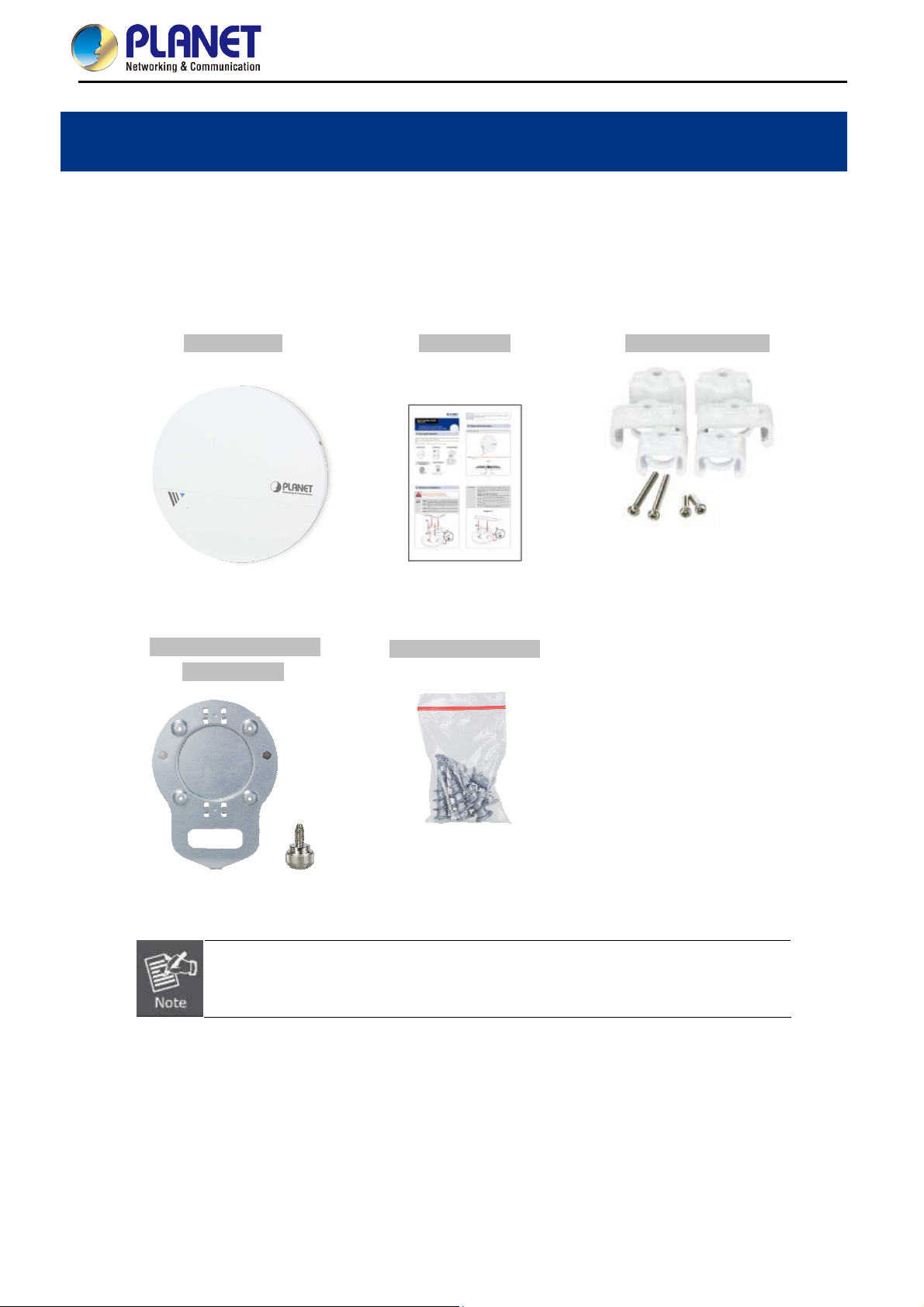
1.1 Package Contents
Thank you for choosing PLANET WDAP-C1750. Before installing the AP, please verify the contents inside the
package box.
WDAP-C1750 Quick Guide T-rail Mounting Kit
Plastic spacer x 2
Long T-rail clip x 2
Short T-rail clip x 2
Long screw x 2
Short screw x 2
Mounting Bracket with
Ceiling Mounting Kit
Thumb Screw
Self-tapping screw x 4
Screw anchor x 4
If there is any item missing or damaged, please contact the seller immediately.
-1-
User Manual of WDAP-C1750
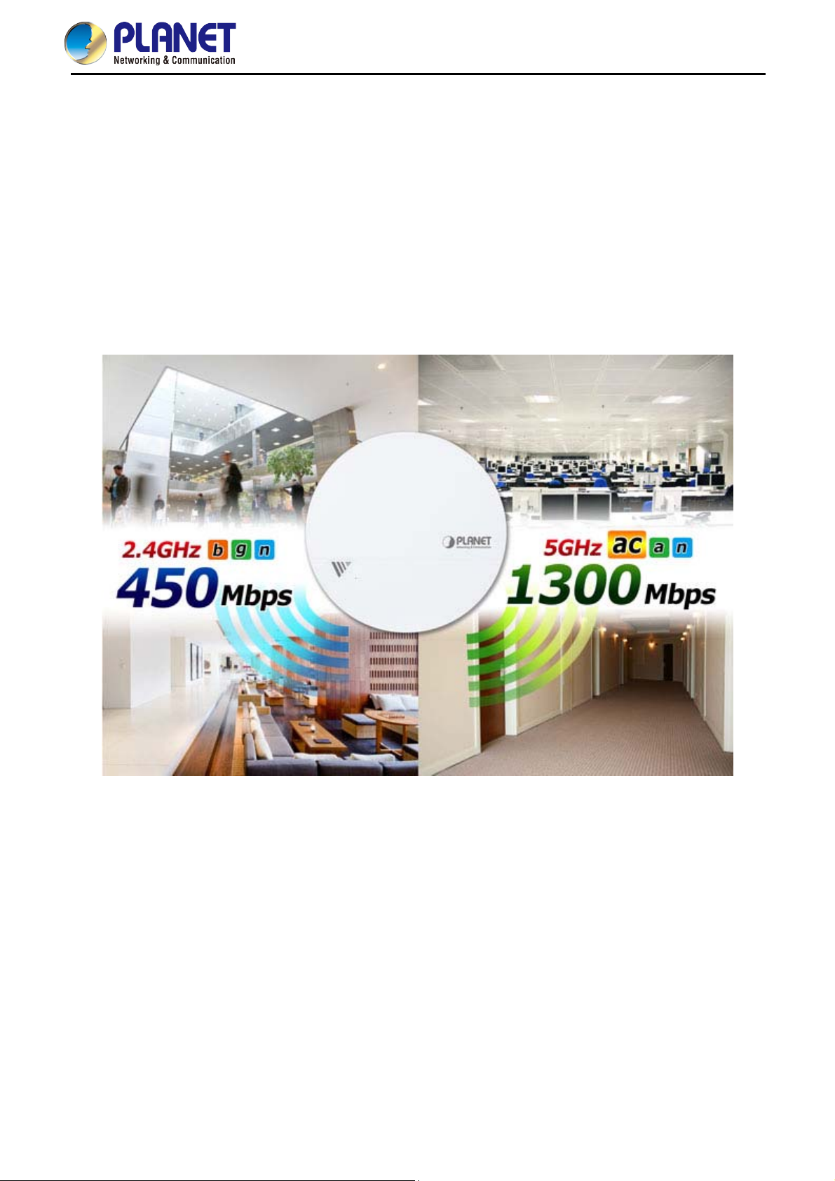
1.2 Product Description
Ultra-high-speed, Enterprise-class Wireless LAN Solution
To meet enterprise demand, PLANET WDAP-C1750 has enhanced security and management features including
SSID-based VLAN, SNMP, internal RADIUS Server and cost-effective NMS (Network Management System). With 3T3R
MIMO IEEE 802.11ac dual-band technology, the WDAP-C1750 provides extreme wireless speed up to 450 +
1300Mbps (2.4GHz + 5GHz). The incredible wireless speed makes it ideal for handling multiple HD video
streams, VoIPs and data sessions stably at the same time, specifically designed for SMBs, hotels, hospitals or
anywhere with high-density network application.
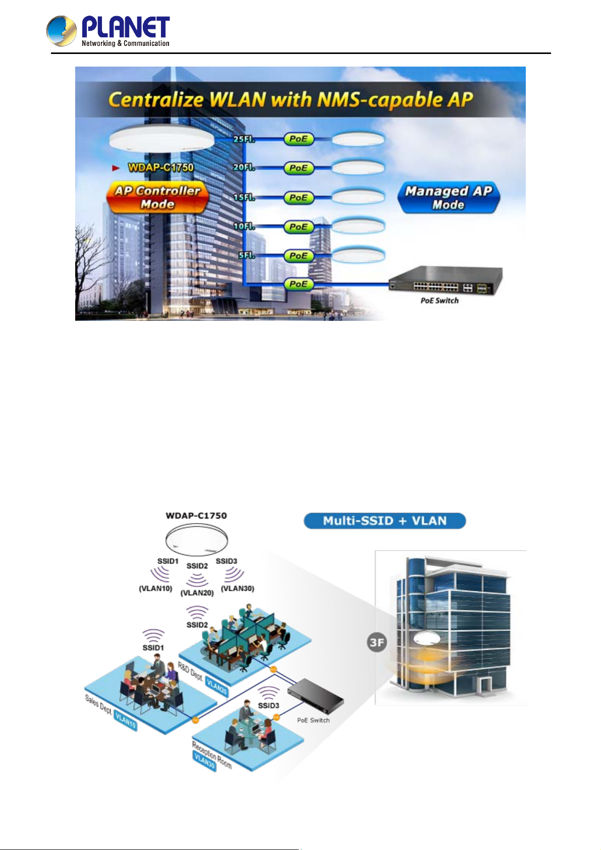
Central Management with NMS
The WDAP-C1750 with NMS (Network Management System) permits users to monitor and manage their entire operations
when in the operation mode. When entering the NMS control platform, the dashboard displays an at-a-glance view of their
wireless networks including system information, managed AP, managed AP group and active client list with real-time
scanning. The graphical zone plan showing the wireless coverage including heat maps, devices and location can be
customized with the floor map you uploaded. With NMS, any WDAP-C1750 can be the controller of a manageable wireless
network.
-2-
User Manual of WDAP-C1750
Secure and Manageable Wireless Network
Besides the WEP/WPA/WPA2 encryption for stations, the WDAP-C1750 is integrated with an internal RADIUS
server and MAC-based ACL to authenticate and protect your wireless LAN to prevent unauthorized wireless
connections. For management purposes, the WDAP-C1750 enables the system administrator to remotely
monitor the wireless network status through the SNMP and the syslog server, and the IEEE 802.1Q tagged
VLAN to be mapped to multiple SSIDs (16 sets of SSIDs per radio) to distinguish the wireless access in the
Internal VLAN topology. The tagged VLAN also allows to be transmitted across the WDS connection and thus it
is the best Wireless LAN solution to enterprises to isolate traffic guests from internal usage.
-3-

User Manual of WDAP-C1750
T-rail Ceiling-mount Design Perfect for Office
The WDAP-C1750 has an elegant, ultra slim, durable ceiling-mount housing, which provides more flexible
deployment options for enterprises. By supporting the standard IEEE 802.3at PoE PD power scheme, the
WDAP-C1750 can be powered and networked by a single UTP cable, effectively eliminating the needs of
dedicated electrical outlets on the ceiling and reducing the cabling cost. Furthermore, the system administrator is
able to arrange PoE schedule by using the managed PoE switch. Besides the standard ceiling-mounting kit, the
WDAP-C1750 provides an extra T-rail mounting kit allowing IT engineers to easily hang bulky APs without any
construction.
Multiple Operation Modes for Various Applications
In the aspect of management, the WDAP-C1750 supports AP Controller and Managed AP modes in NMS
scheme. The WDAP-C1750 being an AP Controller is able to centrally manage up to 5 WDAP-C1750 units
acting as managed APs. As to common wireless application, it supports WDS Bridge PtP, WDS Bridge PtMP
and Repeater modes, through which it provides more flexibility for users when wireless network is established.
Compared with general wireless access point, the WDAP-C1750 offers more powerful and flexible capability for
wireless clients.
-4-
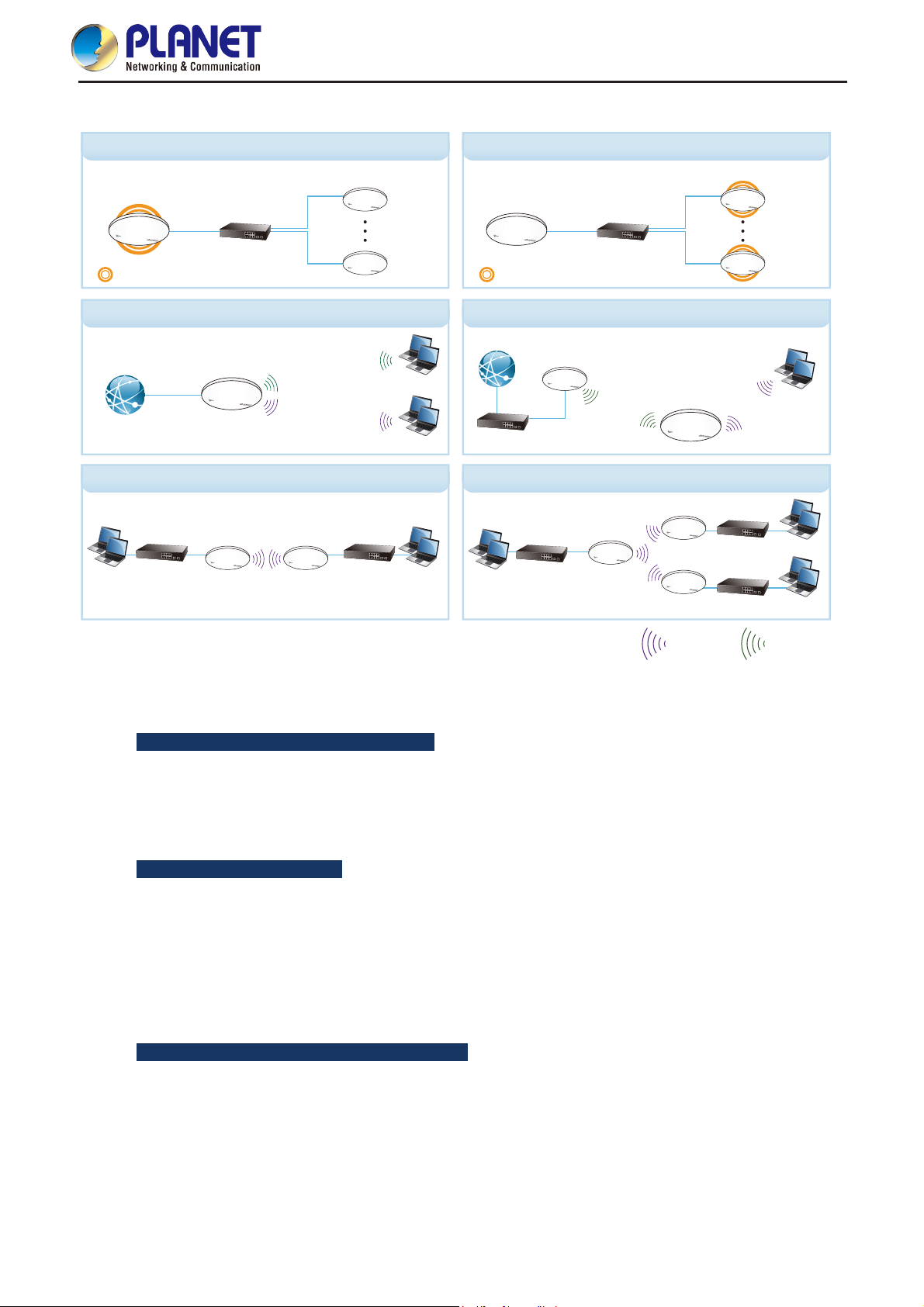
AP Controller Mode Managed AP Mode
WDAP-C1750
WDAP-C1750
Switch
AP Controller Mode Managed AP Mode
AP-1
Up to 5 APs Up to 5 APs
AP-5
WDAP-C1750
AP (Multi-SSID) Mode WDS Repeater Mode
User Manual of WDAP-C1750
WDAP-C1750
AP-1
Switch
AP-5
Internet
WDAP-C1750
SSID-1
SSID-2
Clients
Clients
WDS Bridge-PtP Mode WDS Bridge-PtMP Mode
WDAP-C1750 WDAP-C1750
Clients Clients
Switch
Switch
1.3 Product Features
Standard Compliant Hardware Interface
Complies with IEEE 802.11ac and IEEE 802.11a/b/g/n standards
Internet
Switch
Clients
WDAP-C1750
WDAP-C1750
Switch
WDS
WDAP-C1750
AP
AP
2.4GHz Link
Switch
Switch
Clients
Clients
Clients
5GHz Link
1 x 10/100/1000BASE-T port with IEEE 802.3at PoE PD supported
1 x micro USB 2.0 port for image upgrade and configuration backup/restore
RF Interface Characteristics
2.4GHz (802.11b/g/n) and 5GHz (802.11a/n/ac) concurrent dual band for more efficiency of
carrying high traffic loads
3T3R MIMO technology for enhanced throughput and coverage
Provides multiple adjustable transmit power control
Wireless data transfer rate of up to 1.75Gbps (450Mbps at 2.4GHz + 1300Mbps at 5GHz)
Comprehensive Wireless Advanced Features
Multiple Wireless Modes: AP, Repeater , WDS PtP, WDS PtMP
NMS Operation Modes: AP Controller, Managed AP
Supports up to 16 multi-SSIDs per radio (32 multi-SSIDs per AP)
Supports SSID-based VLAN, tagged VLAN over WDS connection
Supports WMM (Wi-Fi Multimedia) and wireless QoS to enhance the efficiency of multimedia
application
-5-

User Manual of WDAP-C1750
Self-healing (Schedule Reboot) mechanism for reliable connection
Multicast rate adaptation guarantees wireless bandwidth and service quality
Load balancing achieved through the defined number of associated clients per SSID or station idle
timeout control
Secure Network Connection
Advanced security for clients: 64/128-bit WEP, WPA/WPA2, WPA-PSK/WPA2-PSK (TKIP/AES
encryption) and 802.1x RADIUS authentication
Supports WPS (Wi-Fi Protected Setup)
Built-in RADIUS server for authenticating up to 256 user accounts
Supports MAC address filtering up to 256 entries
Wireless Isolation between SSIDs or clients connected to the same SSID
Easy Installation & Management
Ultra slim and durable ceiling-mount design with extra T-rail mounting kit provided for office
environment
Flexible deployment with standard IEEE 802.3at PoE PD supported
Web-based configuration through HTTP/HTTPS/SSH/CLI interface
SNMP-based management interface
Central management with firmware-based NMS (Network Management System) interface
Diagnostic LED and built-in buzzer will sound temporarily to help identify and locate the AP
Supports Syslog Server for sending syslog messages to the external servers for remote tracking
System status monitoring includes DHCP Client and System Log
NMS Management Features
Supports up to 5 managed APs with no additional wireless AP controller
Dashboard display for the system, AP, AP group and associated client information
Zone Plan with heat map view allows user to upload customized floor plan
AP Cluster Management and AP Cluster provisioning
AP bulk firmware upgrade
AP/Client status monitoring
-6-
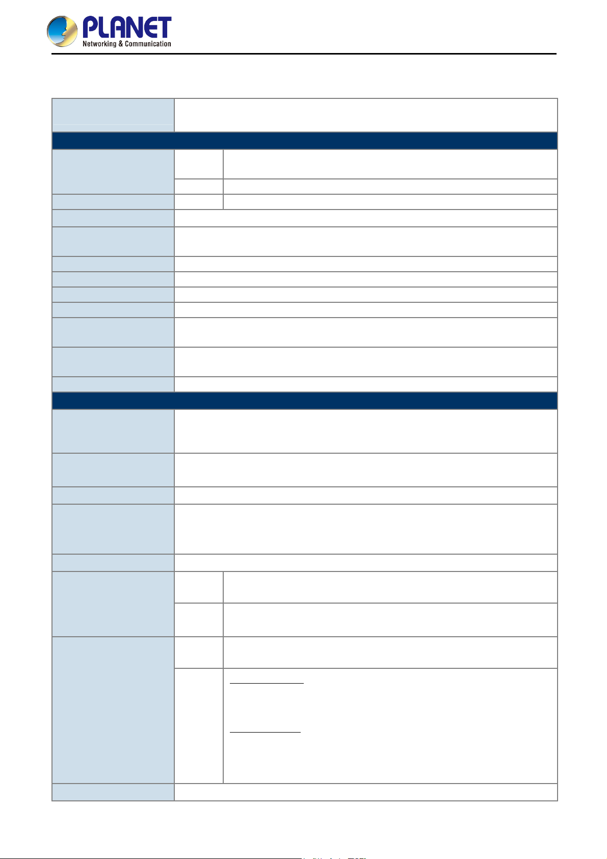
1.4 Product Specifications
User Manual of WDAP-C1750
Product
WDAP-C1750
1750Mbps 802.11ac Dual Band Ceiling-mount Enterprise Wireless Access Point
Hardware Specifications
1 x 10/100/1000BASE-T RJ45 port
Auto-negotiation and auto MDI/MDI-X
Interfaces
LAN
USB 1 x micro USB 2.0 port
Antennas Gain Internal PIFA antenna (3 x 2.4GHz 4dBi, 3 x 5GHz 5dBi)
Button
LED Indicators
Reset button
PWR/Diag LED
Allow LED to turn off via software control
Other Internal buzzer
Material Plastic front panel, metal rear panel
Dimensions (Φ x H) 208 x 31.5 mm
Weight 590g
Power Requirements
Power Consumption
(Max.)
PoE: 802.3at PoE-PD Class 4
12V DC, 2.5A (not included in the standard package)
15W, 19.2W (with USB)
Mounting Ceiling mount
Wireless Interface Specifications
IEEE 802.11ac 5GHz
Standard
IEEE 802.11a/n 5GHz
IEEE 802.11b/g/n 2.4GHz
Antenna Structure
802.11ac: 3T3R MU-MIMO
802.11n: 3T3R MIMO
Modulation DSSS
802.11ac: OFDM (BPSK/QPSK/16QAM/64QAM/256QAM)
Data Modulation
802.11a/g/n: OFDM (BPSK/QPSK/16QAM/64QAM)
802.11b: DSSS (DBPSK/DQPSK/CCK)
Band Mode
Frequency Range
Operating Channels
Channel Width
2.4G/5G concurrent mode
2.4GHz
America -- FCC: 2.412~2.462GHz
Europe -- ETSI: 2.412~2.484GHz
5GHz
America -- FCC: 5.180~5.240GHz, 5.725~5.850GHz
Europe -- ETSI: 5.180~5.240GHz
2.4GHz
America -- FCC: 1~11
Europe -- ETSI: 1~13
America -- FCC:
36, 40, 44, 48, 149, 153, 157, 161, 165
5GHz
Europe -- ETSI:
36, 40, 44, 48
5GHz channel list will vary in different countries according to their regulations.
802.11ac: 20/40/80MHz
-7-
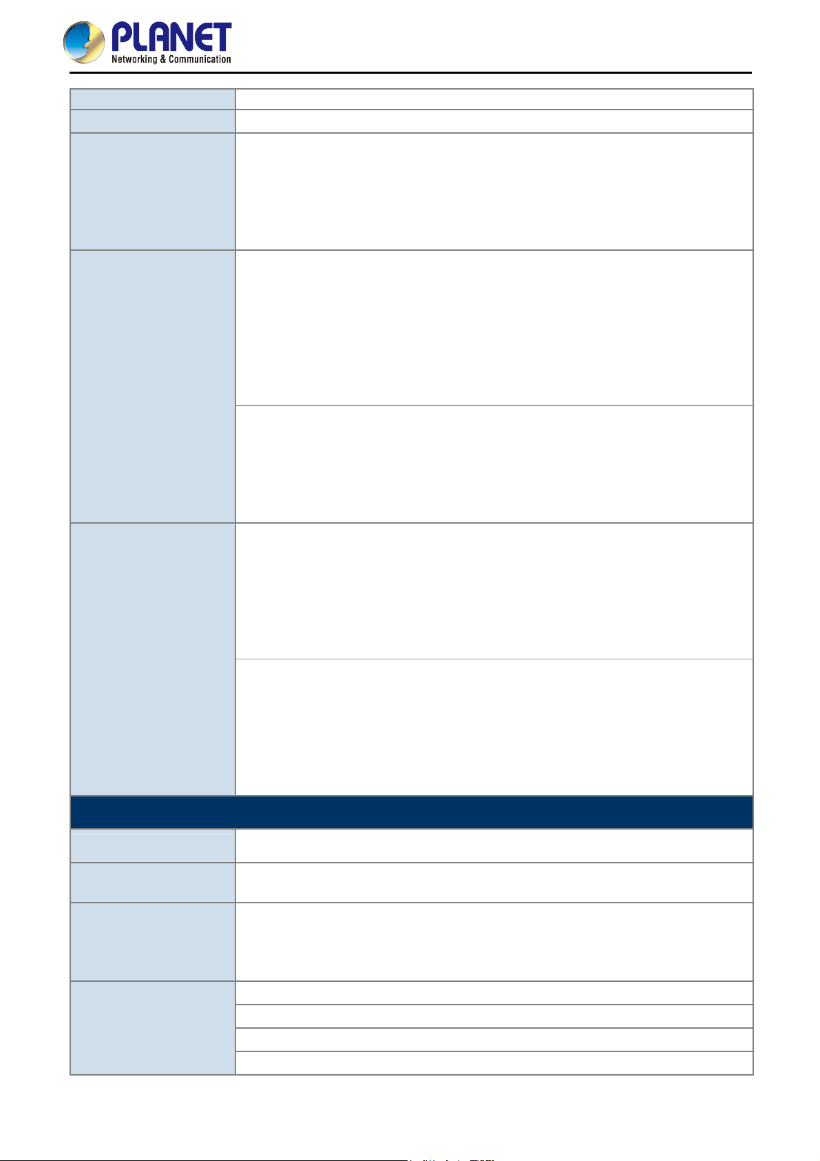
Transmission Speed
Transmission Distance
Max. RF Power
(limited by local
regulation)
Receive Sensitivity
User Manual of WDAP-C1750
802.11n: 20/40MHz
450 + 1300Mbps (2.4GHz + 5GHz)
802.11ac: up to 35m
802.11n: up to 70m
802.11a/b/g: up to 30m
The estimated transmission distance is based on the theory. The actual distance will vary in different
environments.
5GHz:
802.11ac (VHT20/40/80): 27.5dBm @MCS0
802.11ac (VHT20/40/80): 22.5dBm @MCS7
802.11ac (VHT20/40/80): 19.5dBm @MCS9
802.11n (HT20/40): 27.5dBm @MCS0/MCS8
802.11n (HT20/40): 22.5dBm @MCS7/MCS15
802.11a: 26.5dBm @6Mbps
22.5dBm @54Mbps
2.4GHz:
802.11n (HT20/40): 27.5dBm @MCS0
802.11n (HT20/40): 22.5dBm @MCS7
802.11g: 27.5dBm @6Mbps
802.11g: 23.5dBm @54Mbps
802.11b: 27.5dBm @1Mbps
5GHz:
802.11ac (VHT20/40/80): -84dBm @MCS0
802.11ac (VHT20/40/80): -58dBm @MCS9
802.11n (HT20): -90dBm @MCS0, -70dBm @MCS7
802.11n (HT40): -87dBm @MCS0, -68dBm @MCS7
802.11a: -90dBm @6Mbps
802.11a: -71dBm @54Mbps
2.4GHz:
802.11n (HT20/40): -83dBm @MCS0
802.11n (HT20/40): -66dBm @MCS7
802.11g: -86dBm @54Mbps
802.11g: -72dBm @54Mbps
802.11b: -93dBm @1Mbps
802.11b: -85dBm @11Mbps
Software Features
Operation Mode (NMS)
Wireless Mode
Encryption Security
Wireless Security
AP Controller Managed AP
AP (Access Point)
Repeater
WDS PTP (Point to Point)
WDS PTMP (Point to Multipoint)
WEP (64/128-bit) encryption security
WPA/WPA2 (TKIP/AES)
WPA-PSK/WPA2-PSK (TKIP/AES)
802.1x authentication
Wireless MAC address filtering up to 256 entries
Wireless Client Isolation: STA separator, SSID separator
Supports WPS (Wi-Fi Protected Setup)
Enable/Disable SSID broadcast
-8-
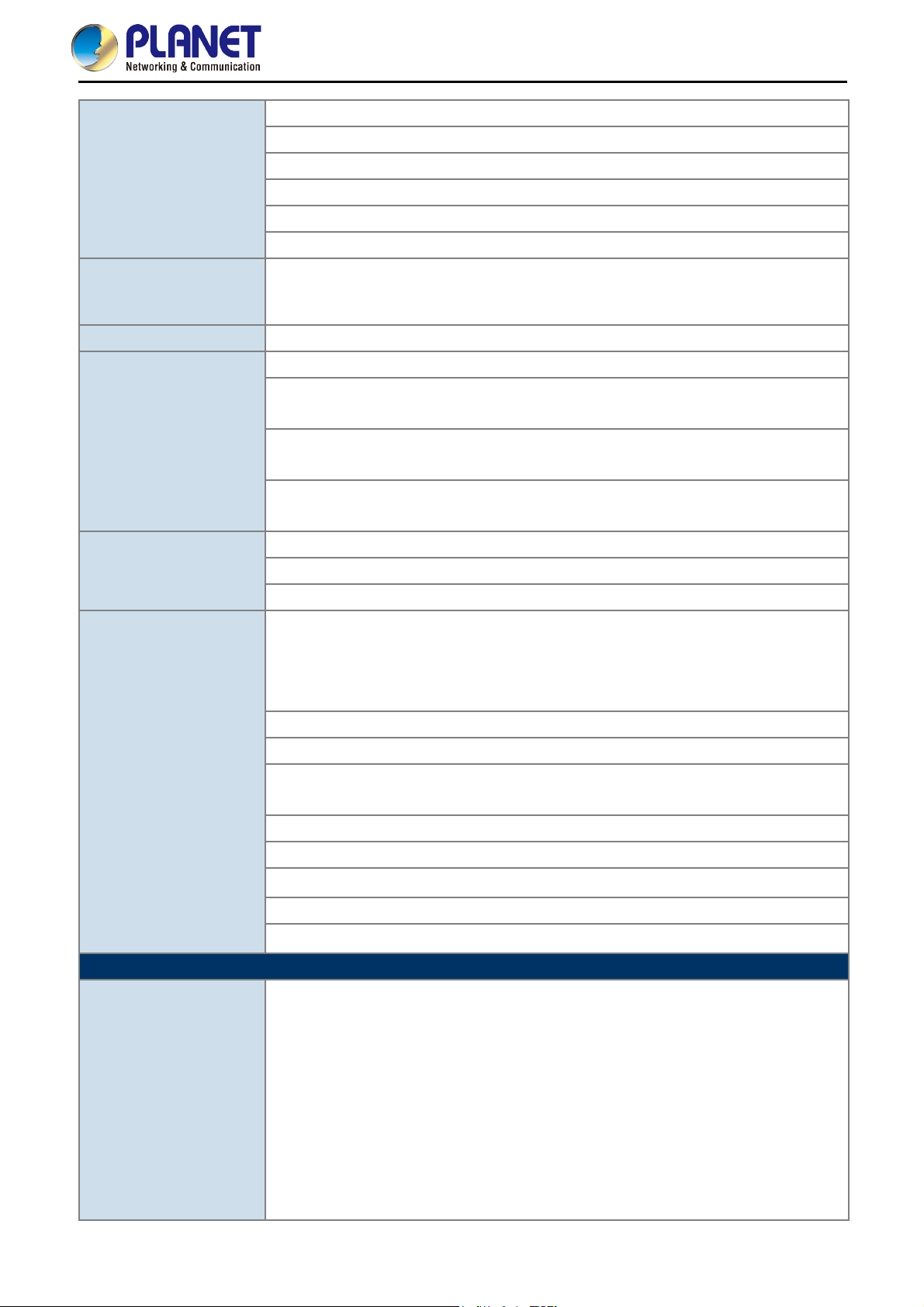
6-level adjustable Tx power (100%, 90%, 75%, 50%, 25%, 10%)
Multiple SSIDs: up to 16 at 2.4GHz and 16 at 5GHz
Wireless Advanced
Tagged VLAN per SSID, tagged VLAN over WDS
Auto-channel selection: enables an AP to determine the best channel available
Rogue AP detection
Provides wireless statistics for system administrator monitoring
Wired: 253
Max. Clients
2.4GHz Wireless: 50
5GHz Wireless: 50
Max. WDS Peers Up to 4 at 2.4GHz and 4 at 5GHz
IEEE 802.11e WMM (Wi-Fi Multimedia)
Station Idle Timeout: Enables and configures it to prevent inactivated clients from
occupying the connection.
QoS
AP Load Balancing: To balance the distribution of wireless client connections across
multiple APs.
Supports multicast rate adaptation mechanism to guarantee the wireless bandwidth
and service quality.
Static IP, DHCP Client, DHCP Server
LAN
Supports 802.1d Spanning Tree (RTSP)
User Manual of WDAP-C1750
System Management
Standards Conformance
IEEE Standards
Supports 802.1Q tagged/untagged VLAN (VID: 1-4095)
NMS firmware-based management interface:
Supports up to 5 managed APs with no additional wireless controller
Features dashboard and zone plan with heat map, AP cluster management,
AP bulk firmware upgrade, AP/client status monitoring
Web-based (HTTP/HTTPS/SSH/CLI) management interface
SNMP v1, v2c, v3 management interface
Built-in RADIUS server with EAP authentication (MS-PEAP)
User account up to 256
SNTP synchronization
Easy firmware upgrade
Supports self-healing (schedule reboot) mechanism for reliable connection
Supports PLANET Smart Discovery Utility
Supports system log and syslog server
IEEE 802.11ac (wave 1, 3T3R, up to 1300Mbps)
IEEE 802.11n (3T3R, up to 450Mbps)
IEEE 802.11g
IEEE 802.11a
IEEE 802.11b
IEEE 802.11i
IEEE 802.3 10BASE-T
IEEE 802.3u 100BASE-TX
IEEE 802.3ab 1000BASE-T
IEEE 802.3x Flow Control
IEEE 802.3az Energy Efficient Ethernet
-9-

IEEE 802.3at Power over Ethernet plus
Other Protocols and
Standards
CSMA/CA, CSMA/CD, TCP/IP, DHCP, ICMP, SNTP
Environment & Certification
Operating: 0 ~ 50 degrees C
Temperature
Storage: -20 ~ 60 degrees C
Operating: 10 ~ 90% (non-condensing)
Humidity
Storage: 5 ~ 90% (non-condensing)
User Manual of WDAP-C1750
Regulatory
FCC, CE
-10-
User Manual of WDAP-C1750
Chapter 2. Hardware Installation
Please follow the instructions below to connect WDAP-C1750 to the existing network devices and your
computers.
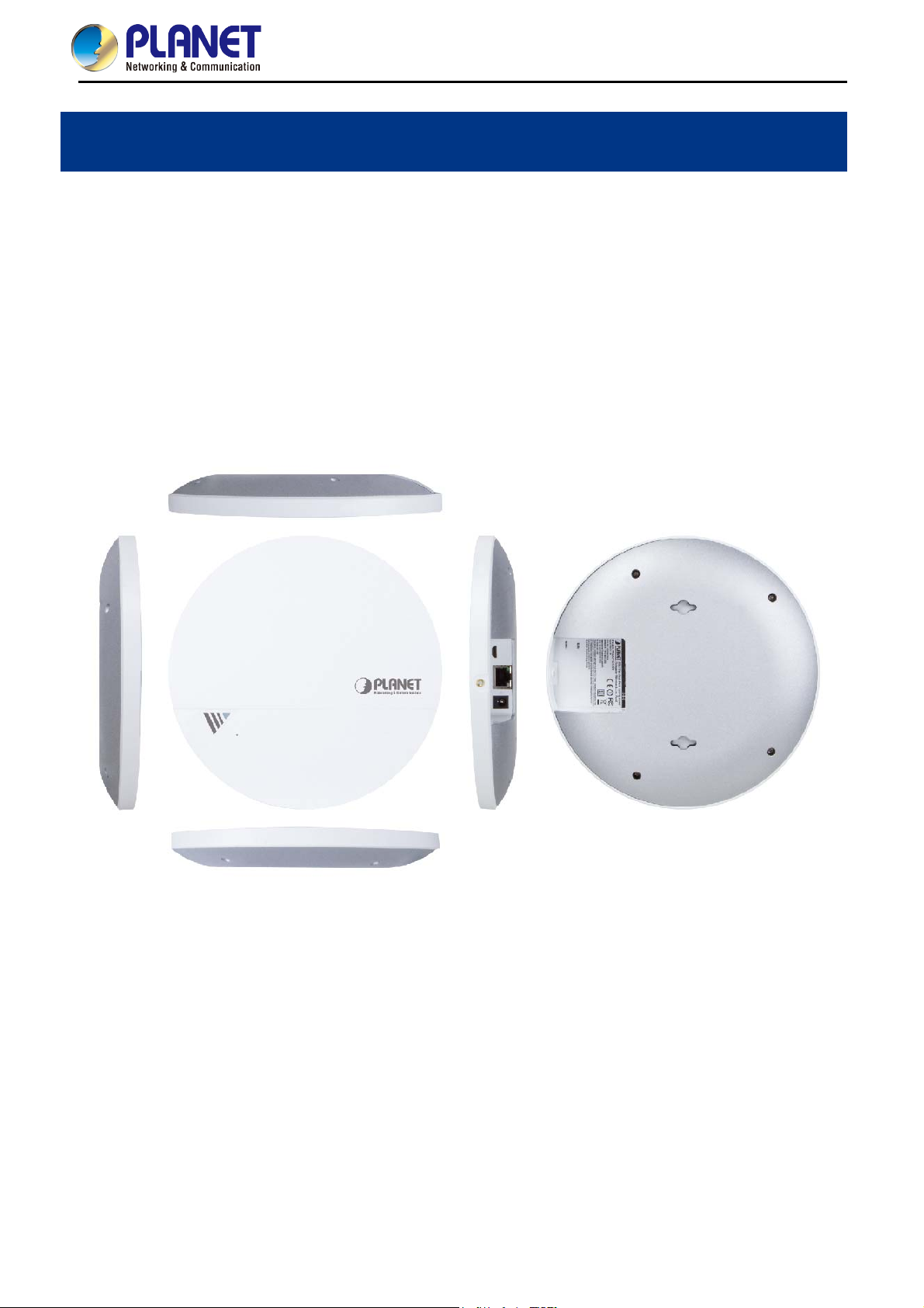
2.1 Product Outlook
Dimensions: (Φ x H)
208 x 31.5 mm
Weight :
590g
Figure 2-1 WDAP-C1750 – Triple View
-11-
User Manual of WDAP-C1750
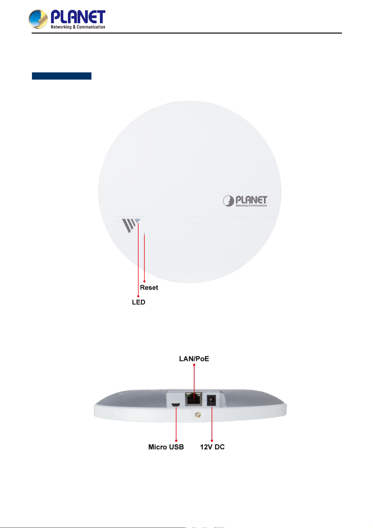
2.1.1 Panel Layout
Figure 2-2 and Figure 2-3 show the hardware interface of the WDAP-C1750.
Hardware Interface
Figure 2-2 WDAP-C1750 Front Panel Layout
Figure 2-3 WDAP-C1750 Side Panel Layout
-12-
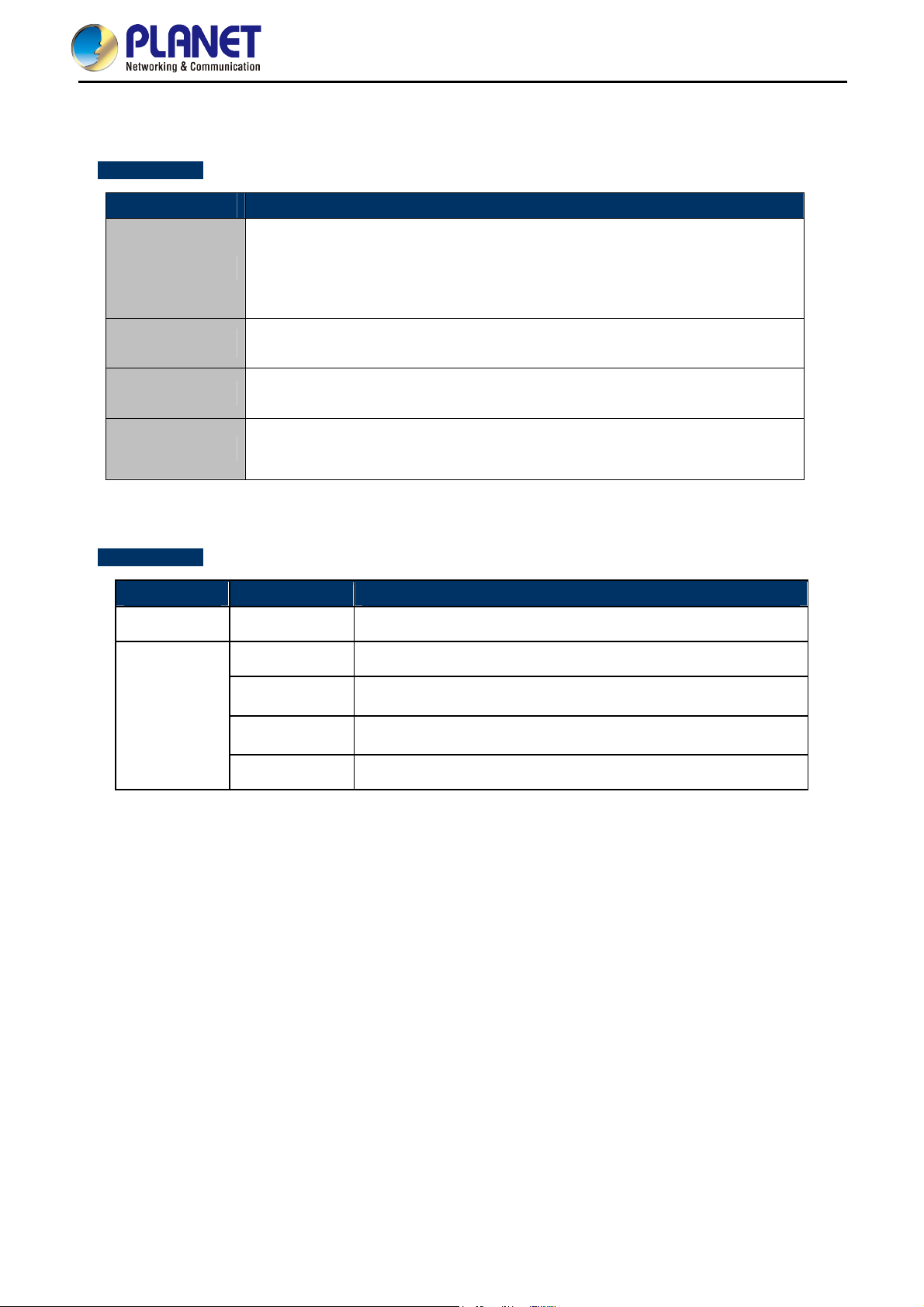
2.1.2 Hardware Description
Port definition
Object Description
DC port supports 12V DC/2.5A power adapter.
12V DC
The WDAP-C1750 can be powered by 802.3at PoE switch. The power adapter
is not included in the standard package and should be purchased separately if
required.
User Manual of WDAP-C1750
LAN/PoE
LAN port with Power over Ethernet (PoE) IN.
Connect any USB memory stick to the micro USB 2.0 port for firmware image
Micro USB
upgrade and system configuration file backup/restore.
To restore to the factory default setting, press and hold the Reset Button by
Reset
using the paper clip for at least 8 seconds, and then release it.
LED definition
LED Color LED STATUS FUNCTION
Purple On The system is initializing.
On
Off
The access point is finished initializing and ready.
The access point is powered off or LED is disabled.
Blue
Slow Flashing
Fast Flashing
Firmware upgrade in progress.
Resetting to factory defaults in progress.
-13-
User Manual of WDAP-C1750
Chapter 3. Connecting to the AP
3.1 System Requirements
Broadband Internet Access Service (Cable/xDSL/Ethernet connection)
One IEEE 802.3at PoE switch (supply power to the WDAP-C1750)
PCs with a working Ethernet Adapter and an Ethernet cable with RJ45 connectors
PCs running Windows 98/ME, NT4.0, 2000/XP, Windows Vista/Win 7, MAC OS 9 or later, Linux, UNIX
or other platforms are compatible with TCP/IP protocols
1. The AP in the following instructions refers to PLANET WDAP-C1750.
2. It is recommended to use Internet Explore 7.0 or above to access the AP.
3.2 Installing the AP
Before installing the AP, make sure your PoE switch is connected to the Internet through the broadband service
successfully at this moment. If there is any problem, please contact your local ISP. After that, please install the
AP according to the following steps. Don't forget to pull out the power plug and keep your hands dry.
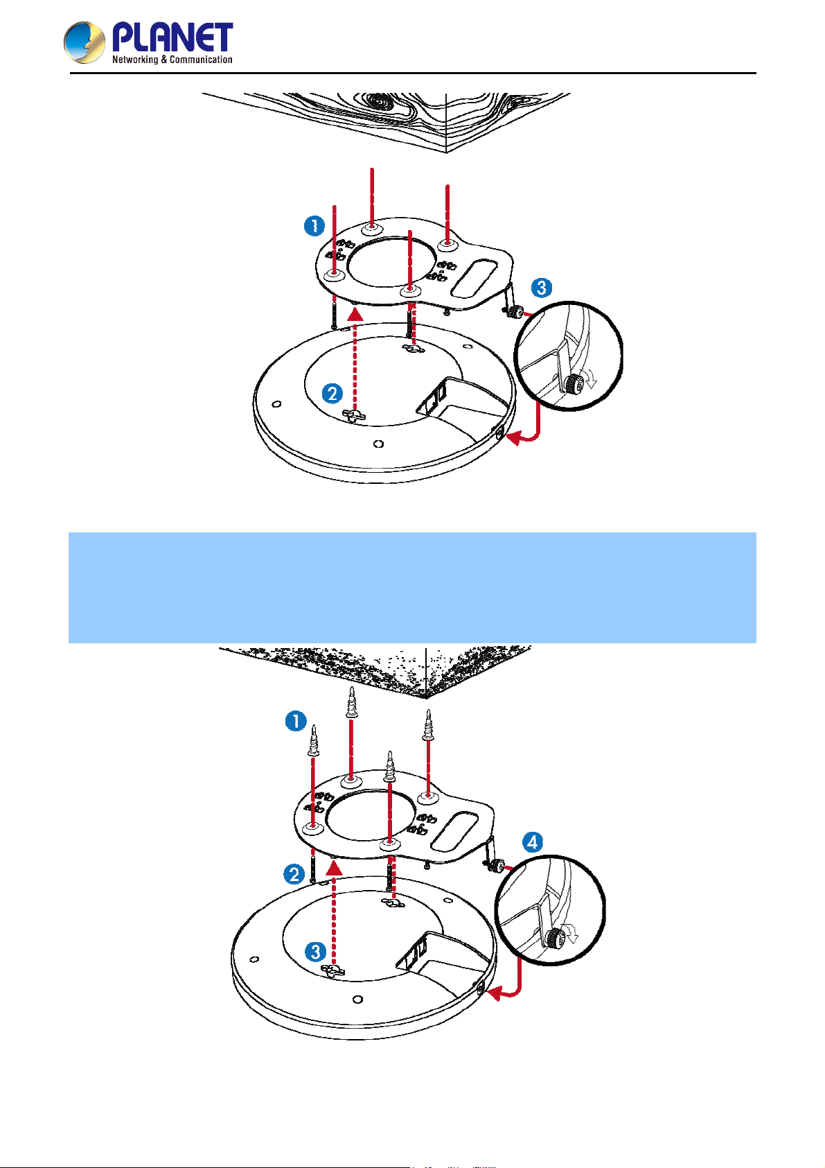
Step 1.
For Wooden Ceilings
1. Place the mounting bracket to a ceiling in your desired location and use the four self-tapping screws
included in the ceiling mounting kit to fix it into place.
2. Attach the AP to the mounting bracket by aligning the grooves in the AP to the ceiling mount.
3. Secure the AP firmly in place using the thumb screw.
-14-
User Manual of WDAP-C1750
Figure 3-1 WDAP-C1750 Installation Diagram 1
For Other Ceilings
1. Drill four holes in your ceiling using the mounting bracket as a guide, and insert the four screw anchors.
2. Align the mounting bracket with your screw anchors and use the four self-tapping screws to fix it into place.
3. Attach the AP to the mounting bracket by aligning the grooves in the AP.
4. Secure the AP firmly in place using the thumb screw.
Figure 3-2 WDAP-C1750 Installation Diagram 2
-15-
User Manual of WDAP-C1750
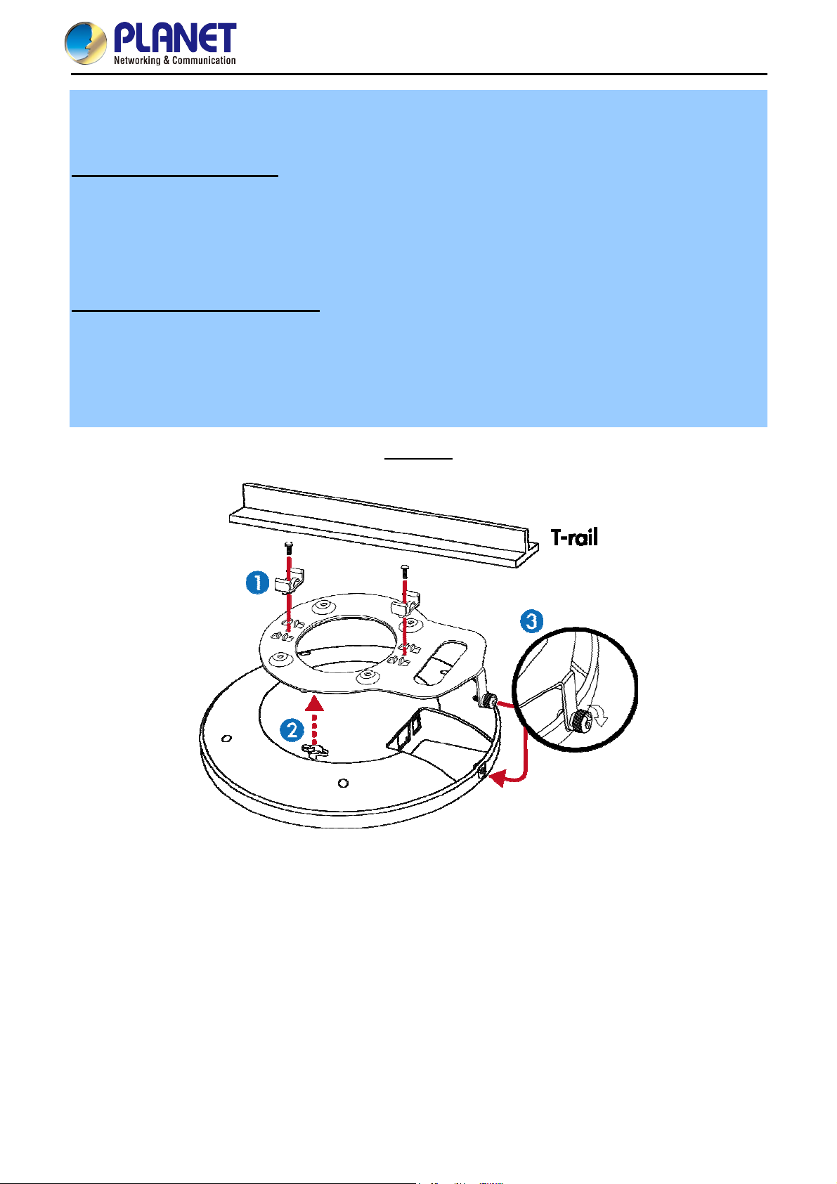
T-rail Mount
To mount the AP to a T-rail, you need to select a T-rail clip whose size must go with the width of the T-rail. Please
follow the instructions below and refer to Diagram 1 or 2.
Diagram 1: Tight-fit installation
1. Attach the T-rail clips to the mounting bracket using the included two short screws.
2. Attach the AP to the mounting bracket by aligning it with the grooves in the AP.
3. Secure the AP firmly in place using the thumb screw.
4. Hang the AP onto the T-rail on the ceiling with the assembled mounting bracket.
Diagram 2: Retention gap installation
1. Pre-assemble the T-rail clips and the plastic spacers to the mounting bracket using the included two long
screws.
2. Attach the AP to the mounting bracket by aligning the grooves in the AP.
3. Secure the AP firmly in place using the thumb screw.
4. Hang the AP onto the ceiling via T-rail with assembled mounting bracket.
Diagram 1
Figure 3-3 WDAP-C1750 T-rail Mount Diagram 1
-16-
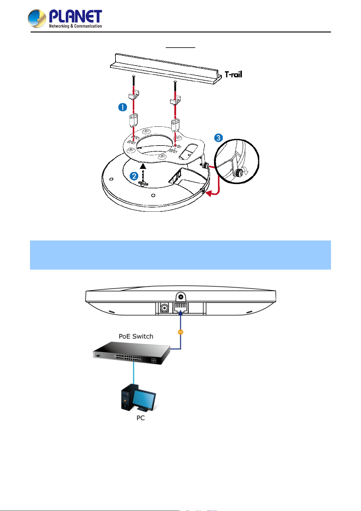
Diagram 2
User Manual of WDAP-C1750
Figure 3-4 WDAP-C1750 T-rail Mount Diagram 2
Step 2.
Plug the RJ45 Ethernet cable into the PoE port of the WDAP-C1750 and the other end of Ethernet cable into the
PoE switch.
Figure 3-5 WDAP-C1750 Installation – connect to PoE switch
-17-

User Manual of WDAP-C1750
Chapter 4. Quick Installation Guide
This chapter will show you how to configure the basic functions of your AP within minutes.
A computer with wired Ethernet connection to the Wireless AP is required for the first-time
configuration.
4.1 Manual Network Setup - TCP/IP Configuration
The default IP address of the WDAP-C1750 is 192.168.1.253. And the default Subnet Mask is 255.255.255.0.
These values can be changed as you want. In this guide, we use all the default values for description.
Connect the WDAP-C1750 with your PC by an Ethernet cable plugging in LAN port on one side and in LAN port
of PC on the other side. Please power on the WDAP-C1750 by PoE switch through the PoE port.
In the following sections, we’ll introduce how to install and configure the TCP/IP correctly in Windows 7. And the
procedures in other operating systems are similar. First, make sure your Ethernet Adapter is working, and refer
to the Ethernet adapter manual if needed.
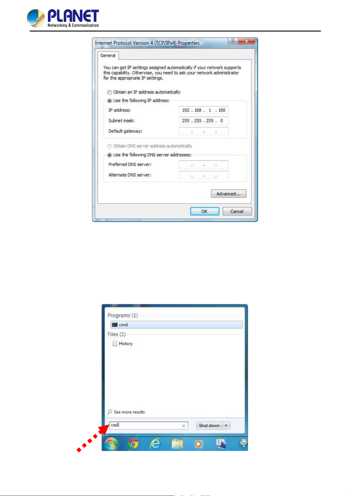
4.1.1 Configuring the IP Address Manually
Summary:
Set up the TCP/IP Protocol for your PC.
Configure the network parameters. The IP address is 192.168.1.xxx (if the default IP address of the
WDAP-C1750 is 192.168.1.253, and the DSL router is 192.168.1.254, the "xxx" can be configured to
any number from 1 to 252), Subnet Mask is 255.255.255.0.
1 Select Use the following IP address radio button, and then configure the IP address of the PC.
2 For example, as the default IP address of the WDAP-C1750 is 192.168.1.253 and the DSL router is
192.168.1.254, you may choose from 192.168.1.1 to 192.168.1.252.
-18-
User Manual of WDAP-C1750
Figure 4-1 TCP/IP Setting
Now click OK to save your settings.
Now, you can run the ping command in the command prompt to verify the network connection between your
PC and the AP. The following example is in Windows 7 OS. Please follow the steps below:
1. Click on Start > Run.
2. Type “cmd” in the Search box.
Figure 4-2 Windows S
-19-
tart Menu
User Manual of WDAP-C1750
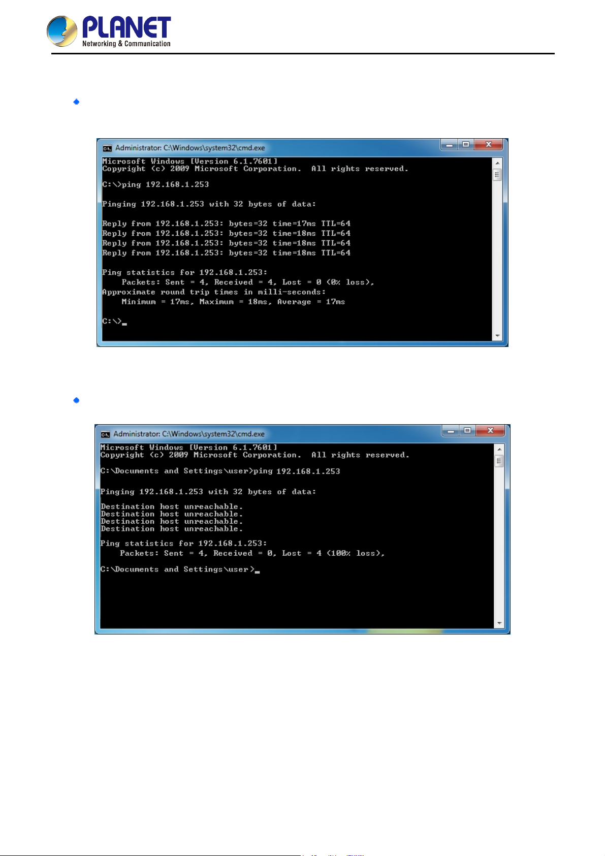
3. Open a command prompt, type ping 192.168.1.253 and then press Enter.
If the result displayed is similar to Figure 4-3, it means the connection between your PC and the AP
has been established well.
Figure 4-3 Successful Result of Ping Command
If the result displayed is similar to Figure 4-4, it means the connection between your PC and the AP
has failed.
Figure 4-4 Failed Result of Ping Command
If the address is 0.0.0.0, check your adapter installation, security settings, and the settings on your AP. Some
firewall software programs may block a DHCP request on newly installed adapters.
-20-
 Loading...