

Page 1

User’s Manual
802.11n 300Mbps
Outdoor Wireless CPE
WBS-202N/WBS-502N
www.PLANET.com.tw
Page 2

Copyright
Copyright 2018 b y PLAN ET Technology Corp. All rights reserved. No part of this publication may be
reproduced, transm itted, transcribed, stored in a retrieval system , or translated into an y language or
computer language, in a n y f orm or b y an y means , electronic, mechanical, magnetic, optical, chemical,
manual or otherwise, without the prior written permission of PLANET.
PLANET makes no representations or warranties, either expressed or implied, with respect to the
contents hereof and specif ically disclaim s any warranties, m erchantability or fitnes s for any particular
purpose. Any soft ware d es c ribed in th is manual is sold or licensed "as is". Sh ou l d th e pr o grams prove
defective following their purchase, th e buyer (and not PL ANET, its distributor, or its dealer) assum es
the entire cost of all necessary servicing, repair, and any incidental or consequential damages resulting
from any defect in the soft ware. Further, PLANET reserves the right to revise thi s publication and to
make changes fr om time to tim e in the c onte nts h ereof withou t obl igati on to not if y any person of such
revision or changes.
All brand and product names mentioned in this manual are trademarks and/or registered trademarks of
their respective holders.
Federal Communication Commission Interference Statemen t
This equipment has be en tested and found to com ply with the limits for a Class B digital
device, pursuant to Part 15 of FCC Rules. These limits are designed to provide reasonable
protection against harmful interference in a residential installation. This equipment
generates, uses, and can radi ate radio f requenc y energ y and, if not ins talled and used in ac cordanc e
with the instructions , may cause harm ful interference to radio comm unications. However, there is no
guarantee that interference will not occur in a particular installation. If this equipment does cause
harmful interference to radio or television reception, which can be determined by turning the equipment
off and on, the user is enc ouraged to try to correct th e interference by one or mor e of the following
measures:
1. Reorient or relocate the receiving antenna.
2. Increase the separation between the equipment and receiver.
3. Connect the equipm ent into an outlet on a circuit differ ent from that to which the recei ver is
connected.
4. Consult the dealer or an experienced radio technician for help.
FCC Caution
To assure continued compliance, use only shielded interface cables when connecting to computer or
peripheral devices. An y changes or modifications not expressl y approved by the party responsible
for compliance could void the user’s authority to operate the equipment.
This device complies with Part 15 of the FCC Rules. Operation is subject to the following two
conditions:
(1) This device may not cause harmful interference
(2) This device must accept any interference received, including interference that may cause undesired
operation.
I
Page 3

limited to 10
Military Radiolocation use. Refarming of the 2.4 GHz
FCC Radiation Exposure Statement
This equipment complies with FCC radiation exposure limits set forth for an uncontrolled
environment. This equipment should be installed and operated with minimum distance 26cm
between the radiator & your body.
CE Compliance Statement
This device meets the R ED 2014/53/EU requirements on the lim itation of exposure of the g eneral
public to electromagnetic fields by way of health protection. The device complies with RF
specifications when it is used at a safe distance of 20 cm fr om your body.
Safety
This equipment is designed with the utmost care for the safety of those who install and use it.
However, special attention must be paid to th e dangers of electric shock and st atic electricit y when
working with electrical equipment. All guidelines of this and of the computer manufacture must
therefore be allowed at all times to ensure the safe use of the equipment.
National Restrictions
This device is intended for home and office use in all EU countries (and other countries following the EU
directive 1999/5/EC) without any limitation except for the countries mentioned below:
Country Restriction Reasons/remarks
Bulgaria None
Outdoor use;
France
Italy None
Luxembourg None
Norway Implemented
Russian
Federation
Note: Please don’t use the product outdoors in Fran ce.
mW e.i.r.p. within the band
2454-2483.5 MHz
None Only for indoor applications
General authorization r eq uire d f or out door use and
public service
band has been ongoing in recent years to allow current
relaxed regulation. Full implem entat ion plan ned 2012
If used outside of own premises, general authorization is
required
General authorization required for network and service
supply(not for spectrum)
This subsection does not appl y f or the geogra phical ar ea
within a radius of 20 km from the centre of Ny-Ålesund
WEEE regulation
To avoid the potential effects on the environment and human health as a result of the
presence of hazardous substances in electrical and electronic equipment, end users of
electrical and electronic equipment should understand the meaning of the crossed-out
wheeled bin symbo l. Do not dispose of W EEE as unsorted municipal waste and have to
collect such WEEE separately.
I
Page 4

Revision
User Manual of PLANET 802.11n 300Mbps Outdoor Wireless CPE
Model: WBS-202N / WBS-502N
Rev: 1.0 (June, 2018)
Part No. EM-WBS-202N_WBS-502N _v1.0 (2081-E10730-000)
II
Page 5

CONTENTS
Chapter 1.Product Introduction ........................................................................................................... 1
Package Contents ............................................................................................................... 1 1.1
Product Description ............................................................................................................ 2 1.2
Product Features ................................................................................................................. 6 1.3
Product Specifications ....................................................................................................... 7 1.4
Chapter 2.Hardware Installation ........................................................................................................ 10
Product Outlook ................................................................................................................ 10 2.1
Port and Button ....................................................................................................... 12
2.1.1
2.1.2 Hardware Des cr ipt ion ............................................................................................. 12
Chapter 3.Connecting to the CPE ..................................................................................................... 13
System Requirements ...................................................................................................... 13 3.1
Installing the CPE .............................................................................................................. 13 3.2
Chapter 4.Quick Installation Guide ................................................................................................... 15
Manual Network Setup -- TCP/IP Configuration ............................................................. 15 4.1
Configuring the IP Address Manually ..................................................................... 15
4.1.1
Starting Setup in the Web UI ............................................................................................ 19 4.2
Chapter 5.Configuring the CPE ......................................................................................................... 20
Wizard ................................................................................................................................. 20 5.1
Gateway Mode ................................................................................................................... 21 5.2
WAN Settings .......................................................................................................... 22
5.2.1
5.2.2 Wireless .................................................................................................................. 23
Repeater Mode .................................................................................................................. 24 5.3
WISP Mode ......................................................................................................................... 26 5.4
AP Mode ............................................................................................................................. 27 5.5
Super WDS Mode .............................................................................................................. 28 5.6
Advanced ........................................................................................................................... 30 5.7
Device Status .......................................................................................................... 30
5.7.1
5.7.2 Wireless .................................................................................................................. 34
5.7.3 Network ................................................................................................................... 39
5.7.4 Firewall.................................................................................................................... 45
5.7.5 Management ........................................................................................................... 48
Chapter 6.Quick Connection to a Wireless Network ....................................................................... 55
Windows XP (Wireless Zero Configuration) ................................................................... 55 6.1
Windows 7 (WLAN AutoConfig) ....................................................................................... 57 6.2
Mac OS X 10.x .................................................................................................................... 60 6.3
III
Page 6

iPhone/iPod Touch/iPad ................................................................................................... 64 6.4
Appendix A: Planet Smart Discovery Utility ..................................................................................... 67
Appendix B: FAQs ............................................................................................................................... 68
Q1: How to set up the AP Client Connection ........................................................................... 68
Q2: How to set up the WDS Connection .................................................................................. 72
Appendix B: Troubleshooting ............................................................................................................ 78
Appendix C: Glossary ......................................................................................................................... 80
IV
Page 7

FIGURE
FIGURE 2-1 WBS-202N/502N FRONT SIDE ............................................................................................. 10
FIGURE 2-2 WBS-202N/502N REAR SIDE ............................................................................................... 10
FIGURE 2-3 WBS-202N RIGHT SIDE ........................................................................................................ 11
FIGURE 2-4 WBS-502N RIGHT SIDE ........................................................................................................ 11
FIGURE 2-5 WBS-202N/WBS-502N INTERFACE ...................................................................................... 12
FIGURE 3-1 CONNECT THE ANTENNA ........................................................................................................ 13
FIGURE 3-2 CONNECT THE ETHERNET CABLE ............................................................................................ 14
FIGURE 3-3 CONNECT THE POE INJECTOR ................................................................................................ 14
FIGURE 4-1 TCP/IP SETTING ................................................................................................................... 16
FIGURE 4-2 WINDOWS START MENU ........................................................................................................ 17
FIGURE 4-3 SUCCESSFUL RESULT OF PING COMMAND .............................................................................. 17
FIGURE 4-4 FAILED RESULT OF PING COMMAND ....................................................................................... 18
FIGURE 4-5 LOGIN BY DEFAULT IP ADDRESS ............................................................................................. 19
FIGURE 4-6 LOGIN WINDOW ..................................................................................................................... 19
FIGURE 5-1 MAIN MENU .......................................................................................................................... 20
FIGURE 5-2 OPERATION MODE ................................................................................................................. 21
FIGURE 5-3 GATEWAY MODE .................................................................................................................... 21
FIGURE 5-4 GATEWAY- STATIC IP ............................................................................................................. 22
FIGURE 5-5 GATEWAY – PPPOE (ADSL).................................................................................................. 22
FIGURE 5-6 GATEWAY – DHCP ................................................................................................................ 23
FIGURE 5-7 GATEWAY – WIRELESS .......................................................................................................... 23
FIGURE 5-8 REPEATER MODE .................................................................................................................. 24
FIGURE 5-9 REPEATER MODE - SCAN AP ................................................................................................. 25
FIGURE 5-10 REPEATER MODE - SELECT AP ............................................................................................ 25
FIGURE 5-11 WISP MODE ....................................................................................................................... 26
FIGURE 5-12 WISP MODE – SELECT AP .................................................................................................. 26
FIGURE 5-13 WISP MODE – SELECT WAN TYPE ...................................................................................... 27
FIGURE 5-14 AP MODE ........................................................................................................................... 27
FIGURE 5-15 SUPER WDS MODE ............................................................................................................ 28
FIGURE 5-16 SUPER WDS MODE – AP1 .................................................................................................. 29
FIGURE 5-17 SUPER WDS MODE – AP2 .................................................................................................. 29
FIGURE 5-18 ADVANCED .......................................................................................................................... 30
FIGURE 5-19 STATUS ............................................................................................................................... 30
FIGURE 5-20 WIRELESS STATUS .............................................................................................................. 31
FIGURE 5-21 LAN STATUS ....................................................................................................................... 32
FIGURE 5-22 WAN STATUS ...................................................................................................................... 33
FIGURE 5-23 BASIC SETTINGS ................................................................................................................. 34
FIGURE 5-24 VIRTUAL AP ........................................................................................................................ 35
FIGURE 5-25 ACCESS CONTROL - ACCESS ALL ......................................................................................... 35
FIGURE 5-26 ACCESS CONTROL – ALLOW LISTED ..................................................................................... 36
FIGURE 5-27 ADVANCED SETTINGS .......................................................................................................... 37
FIGURE 5-28 LAN SETTINGS ................................................................................................................... 39
V
Page 8

FIGURE 5-29 IP-MAC BIND ..................................................................................................................... 39
FIGURE 5-30 VLAN ................................................................................................................................. 40
FIGURE 5-31 SNMP ................................................................................................................................ 41
FIGURE 5-32 STATIC IP ............................................................................................................................ 41
FIGURE 5-33 PPPOE (ADSL) .................................................................................................................. 42
FIGURE 5-34 DHCP ................................................................................................................................ 43
FIGURE 5-35 WAN ADVANCED SETTINGS .................................................................................................. 44
FIGURE 5-36 IP/PORT FILTERING ............................................................................................................. 45
FIGURE 5-37 MAC FILTERING .................................................................................................................. 46
FIGURE 5-38 URL FILTERING ................................................................................................................... 46
FIGURE 5-39 PORT FORWARDING............................................................................................................. 47
FIGURE 5-40 DMZ .................................................................................................................................. 48
FIGURE 5-41 SYSTEM TIME ...................................................................................................................... 48
FIGURE 5-42 SIGNAL TRAC KI NG ............................................................................................................... 49
FIGURE 5-43 DDNS SETTINGS ................................................................................................................. 50
FIGURE 5-44 QOS ................................................................................................................................... 51
FIGURE 5-45 LOGS .................................................................................................................................. 52
FIGURE 5-46 UPGRADE FIRMWARE .......................................................................................................... 53
FIGURE 5-47 SYSTEM .............................................................................................................................. 53
FIGURE 5-48 USER .................................................................................................................................. 54
FIGURE 6-1 SYSTEM TRAY – WIRELESS NETWORK ICON ........................................................................... 55
FIGURE 6-2 CHOOSING A WIRELESS NETWORK ......................................................................................... 55
FIGURE 6-3 ENTERING THE NETWORK KEY ............................................................................................... 56
FIGURE 6-4 CHOOSING A WIRELESS NETWORK -- CONNECTED .................................................................. 56
FIGURE 6-5 NETWORK ICON ..................................................................................................................... 57
FIGURE 6-6 WLAN AUTOCONFIG ............................................................................................................. 57
FIGURE 6-7 TYPING THE NETWORK KEY ................................................................................................... 58
FIGURE 6-8 CONNECTING TO A NETWORK ................................................................................................. 58
FIGURE 6-9 CONNECTED TO A NETWORK .................................................................................................. 59
FIGURE 6-10 MAC OS – NETWORK ICON .................................................................................................. 60
FIGURE 6-11 HIGHLIGHTING AND SEL EC TIN G THE WIRELESS NETWORK ..................................................... 60
FIGURE 6-12 ENTER THE PASSWORD ....................................................................................................... 61
FIGURE 6-13 CONNECTED TO THE NETWORK ............................................................................................ 61
FIGURE 6-14 SYSTEM PREFERENCES ....................................................................................................... 62
FIGURE 6-15 SYSTEM PREFERENCES -- NETWORK ................................................................................... 62
FIGURE 6-16 SELECTING THE WIRELESS NETWORK .................................................................................. 63
FIGURE 6-17 IPHONE – SETTINGS I CON .................................................................................................... 64
FIGURE 6-18 WI-FI SETTING .................................................................................................................... 64
FIGURE 6-19 WI-FI SETTING – NOT CONNECTED ...................................................................................... 65
FIGURE 6-20 TURNING ON WI-FI .............................................................................................................. 65
FIGURE 6-21 IPHONE -- ENTERING THE PASSWORD ................................................................................... 66
FIGURE 6-22 IPHONE -- CONNECTED TO THE NETWORK ............................................................................ 66
VI
Page 9
User Manual of WBS-202N/WBS-502N
Chapter 1. Product Introduction
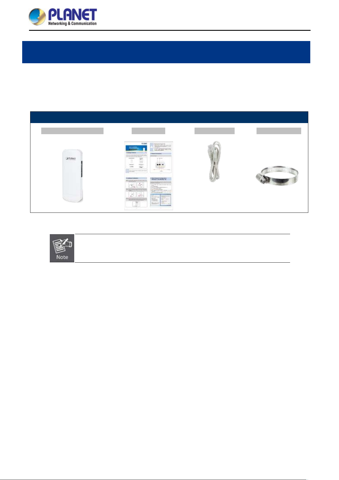
Package Contents 1.1
Thank you for choosing P LANET WBS-202N or WBS-502Ne Wireless AP. Please verify the contents inside t he
package box.
Package Contents of WBS-202N/WBS-502N
WBS-202N / WBS-502N Quick Guide Ethernet Cable Mounting Strap
If there is any item missing or damaged, please contact the seller immediately.
-1-
Page 10

User Manual of WBS-202N/WBS-502N
Product Description 1.2
Flexible and Reliable Outdoor Characteristics
With the standard IEEE 802.3af/at Power over Ethernet (PoE) design, the WBS-202N and WBS-502N (outdoor
wireless CPE) can be easily installed in the areas wh ere power outlets ar e not availa ble. The outdoor wireless
CPE is definitely suitable f or wireless IP surveillance, and bridg e link of building to building and b ackbone of
public service. Addition ally, the self-healing capab ility keeps connec tion alive all the tim e. With the IP55-rated
outdoor enclosure, the o utd oor w irel ess CPE can perform normally under rigorous weather conditions, meaning
it can be installed in any harsh, outdoor environments
Designed for Various Requirements
The outdoor wireless CPE is specially des igned for long-distance outd oor surveillance and wire less backhaul
solutions that are c apable of establishing s table bridg e connection through the e mbedded ante nna. To provide
maximum performance, the outdo or wir e less CP E can implement up to 8 operation modes where a multitude of
applications in communities, warehouses, campuses, harbors, etc. can be made.
-2-
Page 11

User Manual of WBS-202N/WBS-502N
-3-
Page 12
User Manual of WBS-202N/WBS-502N
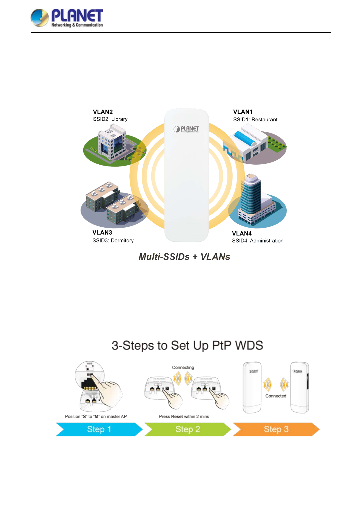
Multiple SSIDs with VLAN Tagging
The outdoor wire les s CP E supports WPA/WPA2, an d t he 802. 1X R ADI U S auth ent ic ati on to sec ure the wireless
connection. Besides, the supported IEEE 802.1Q VLAN allows mult iple VLAN tags to be mapped to multiple
SSIDs to distinguish t he wireless access. This makes it possible for the outdoor wireless CPE to work with
managed Ethernet switches to have VLANs assigned to a different access level and authority.
3 Simple Steps to Set Up WDS
Without needing to enter the Web interface for configuration, the outdoor wireless CPE needs three simple steps
to establish the WDS PtP connection without any difficulty . By just clicking the Pair button on the WBS-202N and
within 2 minutes, you can connect two WBS-202Ns without complicated configuration.
-4-
Page 13

User Manual of WBS-202N/WBS-502N
Optimized Efficiency in AP Management
The brand-new GUI conf ig ur atio n wizar d he lps the system administrator easily set up the outdo or w ire les s C PE
step by step. Besides, the built-in Wi-Fi analyzer provides real-time channel utilization to prevent channel
overlapping to assure greater performance. With the automatic transmission power mechanism, distance control
and scheduling reboot sett ing, the outdoor wireles s CPE is easier for the administrator to deploy and manage
without on-site maintenance. Moreover, you can simply use PLANET AP controller and SAPC (Smart AP
Control), to deliver wireless profiles to multiple APs simultaneously, thus making the central management
simple.
-5-
Page 14

User Manual of WBS-202N/WBS-502N
Product Features 1.3
Industrial Compliant Wireles s LAN and LAN
Compliant with the IEEE 802.11b/g/n and IEEE 802.11a/n wireless technology
2T2R architecture with data rate of up to 300Mbps
Equip ped wit h two 10/100Mbps RJ45 ports with auto MDI/MDI-X supported
Fixed Network Broadband Router
Supported WAN connection types: DHCP, Static IP, PPPoE
Supports Port Forwarding and DMZ for various networking applications
Supports DHCP server in Gateway/WISP mode
RF Interface Characteristics
Built-in 14dBi dual-polarization ant enn a (WBS-202N)
Built-in 15dBi dual-polarization antenn a (WBS-502N)
High output power with multiply-adjustable transmit power control
Outdoor Environmental Character istics
IP55 rating
IEEE 802.3af/at Power over Ethernet design
Operating temperature: -20~70 degrees C
Multiple Operation Modes and Wireless Features
Multiple operation modes: AP, Gateway, Repeater, WDS, WISP
WMM (Wi-Fi multimedia) provides higher priority to multimedia transmitting over wireless
Coverage threshold to limit the weak signal of clients occupying session
Real-time Wi-Fi channel analysis chart and client limit control for better performance
Secure Network Connection
Full encryption supported: WPA/WPA2, WPA-PSK/WPA2-PSK and 802.1X RADIUS authentication
Supports 802.1Q VLAN and SSID-to-VLAN mapping
Supports IP/Port/MAC address/URL filtering, DoS, SPI Firewall
Supports DMZ and Port Forwarding
Bandwidth control per IP address to increase network stability
Easy Installation and Management
3 simple steps to establish WDS connection easily
Supports PLANET AP Controllers in AP mode
Easy discovery by PLANET Smart Discovery
Self-healing mechanism through system auto reboot setting
System status monitoring through remote Syslog Server
Supports PLANET DDNS/ Easy DDNS
-6-
Page 15

User Manual of WBS-202N/WBS-502N
Hardware Features
antenna with
directional antenna with dual
OFDM (BPSK/ QPSK/ 16Q AM/
FCC: 36, 40, 44, 48, 1 49, 153, 157, 161,
ETSI: 36, 40, 44, 4 8, 52, 56, 60, 64, 1 00,
104, 108, 112, 116, 132, 136, 140 (16
Product Specifications 1.4
Model Name
Description
WBS-202N WBS-502N
WBS-202N: 2.4GHz 802.11n 300Mbps Outdoor Wireless CPE
WBS-502N: 5GHz 802.11n 300Mbps Outdoor Wireless CPE
Wireless IEEE802.11b/g/n, 2T2R Wireless IEEE 802.11a/n, 2T2R
Interfaces
PoE: 1 x 10/100BASE-TX, auto-MDI/MDIX, 802.3af/at PoE In
LAN: 1x 10/100BASE-TX, auto-MDI/MDIX
Antennas
Button
Dimensions
Weight
Power Requirements 48V 0.5A, IEEE 802.3af/at PoE+
Power Consumption < 13W
Wireless Interface Specifications
Built-in 14dBi directional
dual polarization
Reset/Pair button, WDS Switch
87 x 38 x 260mm
405g
IEEE 802.11b/g/n
IEEE 802.11i
Standard
IEEE 802.3 10BASE-T
IEEE 802.3u 100BASE-TX
Media Access Control
IEEE 802.3x flow control
CSMA/CA
Built-in 15dBi
polarization
IEEE 802.11a/n
IEEE 802.11i
IEEE 802.3 10BASE-T
IEEE 802.3u 100BASE-TX
IEEE 802.3x flow control
Modulation
Frequency Band
Operating Channels
Max. Transmit Power
(dBm)
802.11g/n: OFDM (BPSK/ QPSK/
16QAM/ 64QAM)
802.11b: DSSS (DBPSK/ DQPSK/
CCK)
FCC: 2.412~2.462GHz
ETSI: 2.412~2.472GHz
FCC: 1~11 Channels
ETSI: 1~13 Channels
FCC: up to 29 ± 1dBm
ETSI: < 20dBm (EIRP)
Receive
Network
Mode
Data Rate
Sensitivity
(dBm)
802.11a/n:
64QAM)
FCC: 5.180~5.240GHz, 5.745~5.825GHz
ETSI: 5.180~5.700GHz
165 (9 channels)
channels)
5GHz channel list will vary in different
countries according to their
regulations.
FCC: up to 27 ± 2dBm
ETSI: < 20dBm (EIRP)
Receive
Network
Mode
Data Rate
Sensitivity
(dBm)
-7-
Page 16

User Manual of WBS-202N/WBS-502N
WAN Type (GW/WISP
Environment & Certification
Operating Temperature
Operating Humidity
802.11b
1Mbps -95
11Mbps -90
6Mbps -90
802.11g
54Mbps -72 54Mbps -75
MCS0/MCS
802.11n
HT20
8
MCS7/MCS
15
MCS0/MCS
802.11n
HT40
8
MCS7/MCS
15
-20 ~ 70 degrees C
5 ~ 90% (non-condensing)
-90
-72/-68
-90
-72/-68
802.11a
802.11n
HT20
802.11n
HT40
6Mbps -92
MCS0/MC
-91
S8
MCS7/MC
-72
S15
MCS0/MC
-88
S8
MCS7/MC
-70
S15
IP Level
ESD Protection
Surge Protection
Regulatory
Software
LAN
mode)
Wireless Modes
Channel Width
IP55
± 8kV air-gap discharge
± 4kV contact discharge
± 4kV
CE, RoHS
Static IP
Supports IP-MAC binding
Static IP
Dynamic IP
PPPoE
Access Point
Gateway
Repeater
WDS (AP/Bridge/Station)
WISP
20MHz, 40MHz
Encryption Type
Wireless Securit y
Max. SSIDs
WPA, WPA-PSK, WPA2, WPA2-PSK, 802.1X
Enable/Disable SSID Broadcast
Wireless MAC address filtering
User Isolation
4
-8-
Page 17

User Manual of WBS-202N/WBS-502N
Max. Wireless Clients
Max. WDS Peers
Wireless QoS
Wireless Advanced
Status Monitoring
VLAN
Self-healing
64 per radio (50 is suggested, depending on usage)
4 (Up to 3 peers by using “One-click WDS”)
Supports Wi-Fi Multimedia (WMM)
Auto Channel Selection
5-level Transmit Power Control (100%, 75%, 50%, 25%, 12.5%)
Client Limit Control, Coverage Threshold
Distance control (Auto Ack Timeout)
Wi-Fi channel analysis chart
Device status, wireless client List
PLANET Smart Discovery
DHCP client table
System Log supports remote syslog server
IEEE 802.1Q VLAN (VID: 3~4094)
SSID-to-VLAN mapping up to 4 SSIDs
Supports auto reboot settings per day/hour
Remote management through PLANET DDNS/ Easy DDNS
Management
Central Management
Configuration backup and restore
Supports UPnP
Supports IGMP Proxy
Supports PPTP/L2TP/IPSec VPN Pass-through
SNMP v1/v2c/v3 support, MIB I/II, Private MIB
Applicable controllers: WAPC-500, WAPC-1000 and Smart AP Control(SAPC)
-9-
Page 18
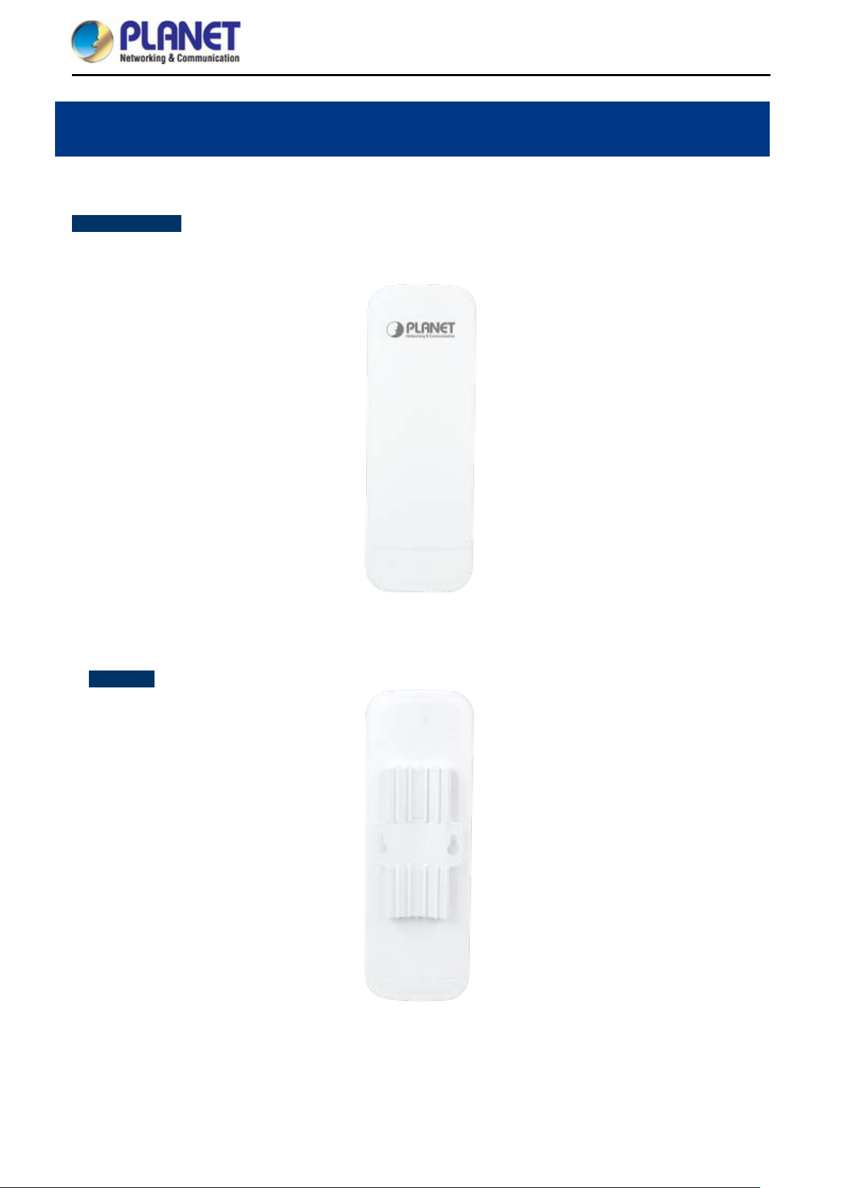
Product Outlook 2.1
WBS-202N/502N
Dimensions: 87 x 38 x 260mm
Front Side :
User Manual of WBS-202N/WBS-502N
Chapter 2. Hardware Installation
Rear Side
Figure 2-1 WBS-202N/502N Front Sid e
Figure 2-2 WBS-202N/502N Rear Side
-10-
Page 19
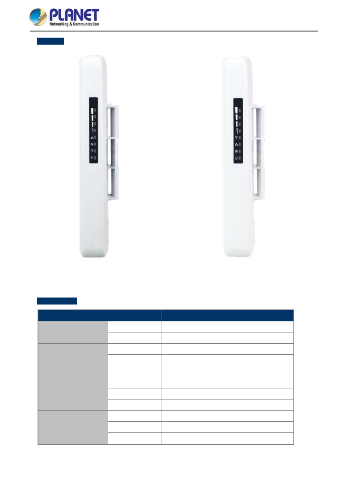
RightSide
User Manual of WBS-202N/WBS-502N
Figure 2-3 WBS-202N Right Side
LED Definition
LED State Meaning
On The device is powered on
Power
Off The device is powered off
On Port linked
WAN Port
Blinking Data is transmitting or receiving data
Off No link
On Port linked
LAN Port
Blinking Data is transmitting or receiving data
Off No link
On The wireless radio is on
Figure 2-4 WBS-502N Right Side
WLAN
Blinking Data is transmitting or receiving over wireless
Off The wireless radio is off
-11-
Page 20
User Manual of WBS-202N/WBS-502N
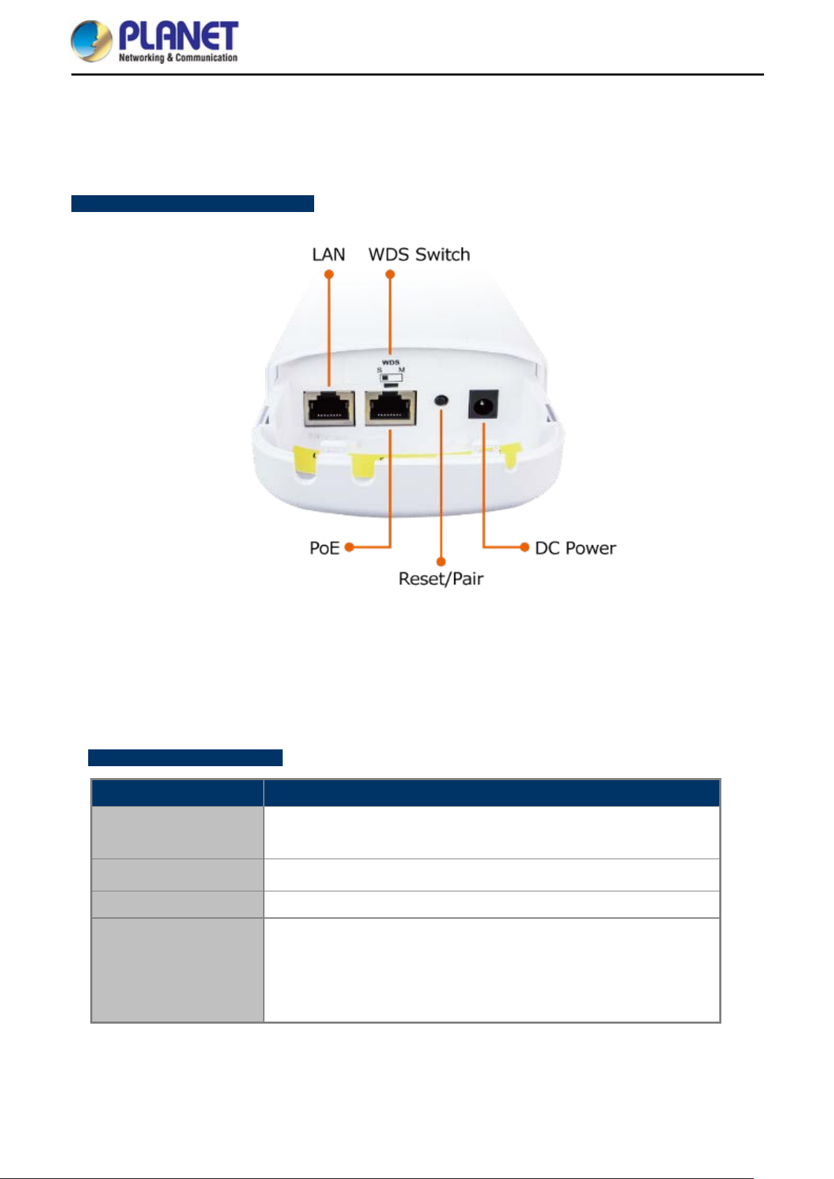
2.1.1 Port and Button
It provides a simple interface monitoring the AP. Figure 2-5 shows the hardware interface of the
WBS-202N/502N.
WBS-202N/502N Hardware Interface:
2.1.2 Hardware Description
Hardware Interface Definition
Object Description
PoE LAN Port
LAN Port
WDS Switch
Reset/Pair Button
Figure 2-5 WBS-202N/WBS-502N Interface
10/100Mbps RJ45 port, auto MDI/MDI-X
10/100Mbps RJ45 port, auto MDI/MDI-X
Position “S” to “M” on the master AP. Stay in “S” on the slave AP.
Press and hold the Reset button on the device for over 15 s econds to
return to the factory default setting.
Press the Pair button within 2 minutes on both sides t o establ ish W DS
PtP connection.
-12-
Page 21
User Manual of WBS-202N/WBS-502N
Chapter 3. Connecting to the CPE
System Requirements 3.1
Broadband Internet Access Service (Cable/xDSL/Ethernet connection)
One IEEE 802.3at PoE switch (supply power to the WBS-202N/502N)
PCs with a working Ethernet adapter and an Ethernet cable with RJ45 connectors
PCs running Windows 98/ME, NT4.0, 2000/XP, Windows Vista / Win 7, MAC OS 9 or later, Linux,
UNIX or other platforms compatible with TCP/IP protocols
1. The CPE in the following instructions refers to PLANET WBS-202N/WBS-502N.
2. It is recommended to use Internet Explorer 11, Firefox or Chrome to access the CPE.
Installing the CPE 3.2
Before installing the CPE, make sure your PoE switch is connected to the Internet through the broadband
service successfully at this moment. If there is any problem, please contact your local I SP. After that, please
install the AP according to the following steps. Don't forget to pull out the power plug and keep your hands dry.
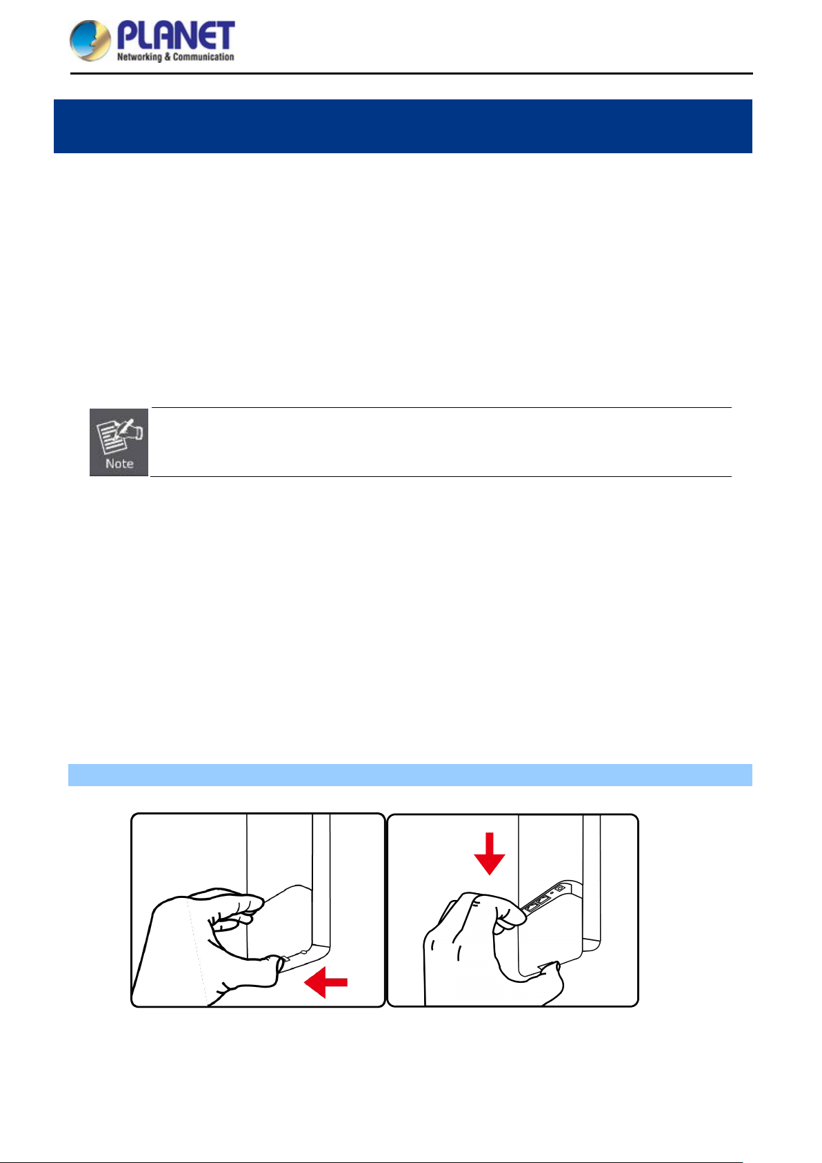
Please install the AP according to the follo wing steps. Don't forget to pull out the power plug and k eep your
hands dry.
Step 1. Push the latch on the bottom of the Outdoor Wireless CPE to remove the sliding cover.
Figure 3-1 Connect the Antenna
-13-
Page 22
User Manual of WBS-202N/WBS-502N
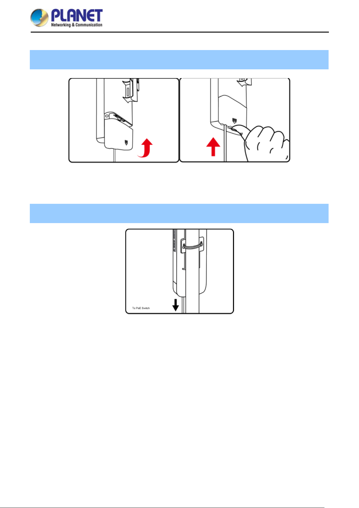
Step 2. Plug the RJ45 Ethernet ca ble into the PoE Port of the O utdoor W ireless CPE. Then, s lide back the
cover to finish the installation.
Figure 3-2 Connect the Ethernet cable
Step 3. Place the mounting strap through the slot o n the back of th e Outdo or W ireless CPE and the n aroun d
the pole. Tighten the mounting strap to secure the Outdoor Wireless CPE.
Figure 3-3 Connect the PoE injector
-14-
Page 23

User Manual of WBS-202N/WBS-502N
Chapter 4. Quick Installation Guide
This chapter will show you how to configure the basic functions of your CPE within minutes.
A computer with wired Ethernet connection to the Wireless CPE is required for the first-time
configuration.
Manual Network Setup -- TCP/IP Configuration 4.1
The default IP address of the WBS-202N/WBS-502N is 192.168.1.253. And the default Subnet Mask is
255.255.255.0. These values can be changed as you want. In this guide, we use all the default values for
description.
Connect the WBS-202N/WBS-502N with your PC by a n Eth ernet c a bl e pl ug gin g i n LAN port on one side and in
LAN port of PC on the othe r side. Please p ower on t he WBS-202N/WBS-502N by PoE switch through the PoE
port.
In the following sections, we’l l introduce how to i nstall and conf igure the T CP/IP correctly in Windows 10. And
the procedures in other oper ating systems are sim ilar. First, make sure your Ethernet A dapter is working, and
refer to the Ethernet adapter manual if needed.
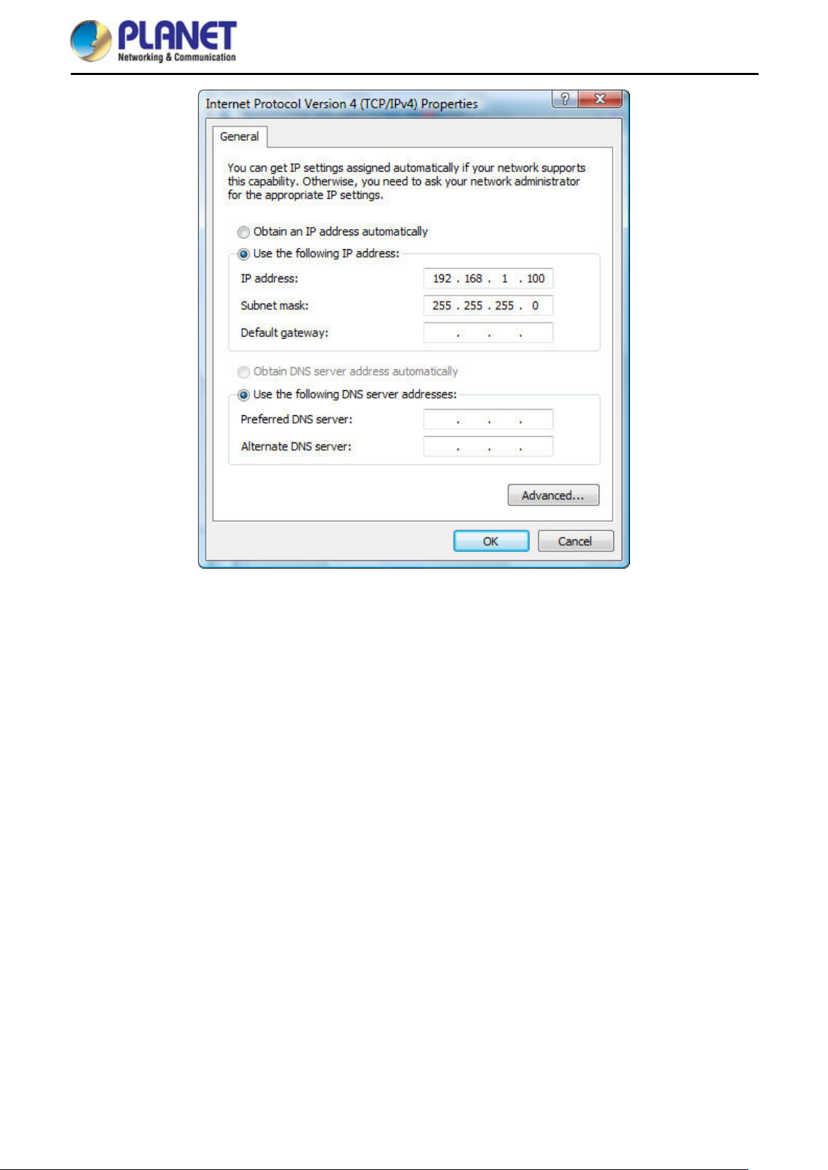
4.1.1 Configuring the IP Address Manually
Summary:
Set up the TCP/IP Protocol for your PC.
Configure the network parameters . The IP address is 192.168.1.xxx (If the d efault IP address of the
WBS-202N/WBS-502N is 192.168.1.253, and the DSL router is 192.168.1.254, the "xxx" can be
configured to any number from 1 to 252.) and subnet mask is 255.255.255.0.
1 Select Use the following IP address, and then configure the IP address of the PC.
2 For example, as the default IP address of the WBS-202N/WBS-502N is 1 92.168. 1.253 and the DSL router
is 192.168.1.254, you may choose from 192.168.1.1 to 192.168.1.252.
-15-
Page 24
User Manual of WBS-202N/WBS-502N
Figure 4-1 TCP/IP Setting
Now click OK to save your settings.
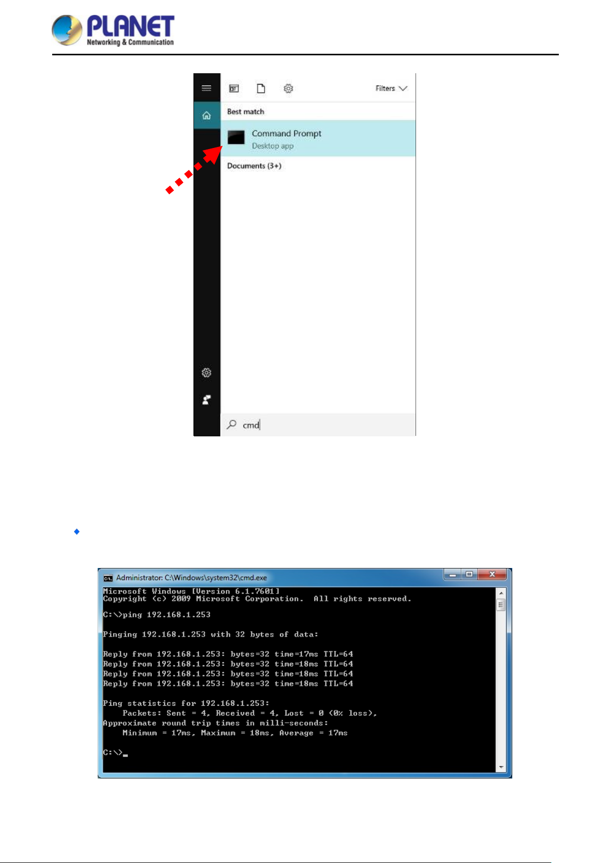
Now, you can run the ping comm and in the command prompt to verif y the network connection between your
PC and the AP. The following example is in Windows 10 OS. Please follow the steps below:
1. Click on Start > Run.
2. Type “cmd” in the Search box.
-16-
Page 25
User Manual of WBS-202N/WBS-502N
Figure 4-2 Windows Start Menu
3. Open a command prompt, type ping 192.168.1.253 and then press Enter.
If the result displa yed is sim ilar to Figure 4-3, it means the connect ion between your PC and the AP
has been established well.
Figure 4-3 Successful Result of Ping Command
-17-
Page 26

User Manual of WBS-202N/WBS-502N
If the result displa yed is similar to Figure 4-4, it means the connection between your PC and the AP
has failed.
Figure 4-4 Failed Result of Ping Command
If the address is 0.0.0 .0, check your adapt er installation, sec urity settings, and the settings on your AP. Som e
firewall software programs may block a DHCP request on newly installed adapters.
-18-
Page 27
User Manual of WBS-202N/WBS-502N
n the screen that
Starting Setup in the Web UI 4.2
It is easy to configure and manage the CPE with the web browser.
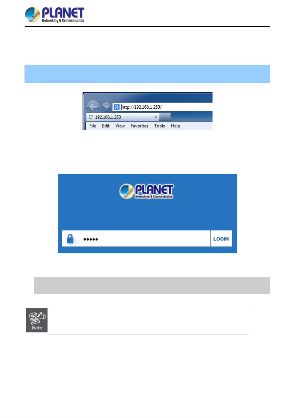
Step 1. To access the configuration utility, open a web-browser and enter the default IP address
http://192.168.1.253 in the web address field of the browser.
Figure 4-5 Login by Default IP Address
After a moment, a login window will appear. Enter admin for the password in lower case letters. T hen click
LOGIN or press the Enter key.
Default IP Address: 192.168.1.253
Default Password: admin
If the above screen does not pop up, it may mean that your web-browser has been set to a
proxy. Go to Tools menu> Internet Options> Connections> LAN Settin g s o
appears, uncheck Using Proxy and click OK to finish it.
Figure 4-6 Login Window
-19-
Page 28

User Manual of WBS-202N/WBS-502N
Chapter 5. Configuring th e CPE
This chapter deli vers a d et ailed pr esent ation of CPE’s functionalities and features 3 main items below, all owing
you to manage the CPE with ease. The screen shots use the WBS-202N as an example.
Figure 5-1 Main Menu
The page includes the following fields:
Object Description
CPU Usage
Wireless Settings
LAN Settings
Super WDS Settings
It shows the CPU usage
Enter the Wireless settings to enable or disable wireless LAN
Enter the LAN settings to change the LAN IP address.
Enter the page to configure the WDS settings
Wizard 5.1
The Wizard guides you to configuring the WBS-202N/WBS-502N in a different mode, including Gateway,
Repeater, WISP, AP and Super WDS mode.
-20-
Page 29

User Manual of WBS-202N/WBS-502N
Figure 5-2 Operation Mode
The default operation mode is Super WDS.
Ga t eway Mode 5.2
Click “Wizard” “Gateway Mode” and the following page will be displayed. This section allows y ou to configure
the Gateway mode.
Figure 5-3 Gateway Mode
-21-
Page 30

User Manual of WBS-202N/WBS-502N
5.2.1 WAN Settings
Static IP
If your ISP offers you static IP Internet connection t ype, select “Static IP" and then enter IP address, subnet
mask, default gateway and primary DNS information provided by your ISP in the corresponding fields.
Figure 5-4 Gateway- Static IP
The page includes the following fields:
Object Description
IP Address
Enter the WAN IP address provide d b y your I SP. Enquire your I SP if you
are not clear
Subnet Mask
Default Gateway
Primary DNS
Enter WAN Subnet Mask provided by your ISP
Enter the WAN Gateway address provided by your ISP
Enter the necessary DNS address provided by your ISP
PPPoE (ADSL)
Select PPPOE if your ISP is using a PPPoE connection and pr ovide you with PP PoE user name and password
info.
Figure 5-5 Gateway – PPPoE (ADSL)
The page includes the following fields:
Object Description
PPPoE Name
PPPoE Password
Enter the User Name provided by your ISP
Enter the password provided by your ISP
-22-
Page 31

User Manual of WBS-202N/WBS-502N
DHCP
Choose “DHCP” and the router will automatically obtain IP address es, subnet masks and gatewa y addresses
from your ISP.
Figure 5-6 Gateway – DHCP
5.2.2 Wireless
Figure 5-7 Gateway – Wireless
The page includes the following fields:
Object Description
WLAN Status Select ON or OFF to enable or disable wireless LAN
Wireless Analyzer
SSID
Press the button to check your wireless environment
It is the wireless network name. The default SSID is PLANET_2.4G or
PLANET_5G
Channel
Select the operating channel you would like to use. The channel
range will be changed by selecting a different domain.
Encryption Select the wireless encryption. The default is None
-23-
Page 32

User Manual of WBS-202N/WBS-502N
Repeater Mode 5.3
Click “Wizard” “Repeater Mode” and the following page wil l be displayed. This section allows you to
configure the Repeater mode.
Figure 5-8 Repeater Mode
The page includes the following fields:
Object Description
Repeater SSID Enter the root AP’s SSID or press “Scan AP” to select
Lockmac
Authentication
Check to lock the root AP’ MAC address
Select the wireless encryption of root AP
Bandwidth Select the operating channel width, “20MHz” or “40MHz”
WDS Passthrough
Check to enable WDS pass through if the root AP is the same model as
client
Press Scan AP to show the root AP that you need to repeat and press Choice to select the AP.
-24-
Page 33

User Manual of WBS-202N/WBS-502N
Figure 5-9 Repeater Mode - Scan AP
Select the authentication and bandwidth which are the same as root AP to establish the connection.
Figure 5-10 Repeater Mode - Select AP
-25-
Page 34

User Manual of WBS-202N/WBS-502N
WISP Mode 5.4
Click “Wizard” “WISP Mode” and the following page will be displa yed. This section al lows you to configure
the WISP mode.
The page includes the following fields:
Object Description
Repeater SSID Enter the root AP’s SSID or press “Scan AP” to select
Lockmac
Authentication
Check to lock the root AP’ MAC address
Select the wireless encryption of root AP
Figure 5-11 WISP Mode
Figure 5-12 WISP Mode – Select AP
-26-
Page 35

User Manual of WBS-202N/WBS-502N
Figure 5-13 WISP Mode – Select WAN type
AP Mode 5.5
Click “Wizard” “AP Mode” and t he follow ing page will be displa yed. This sec tion allows you to configure the
AP mode.
Figure 5-14 AP Mode
The page includes the following fields:
Object Description
WLAN Status Select “ON” or “OFF” to enable or disable wireless LAN
Wireless Analyzer
SSID
Press the button to check your wireless environment
It is the wireless network name. The def ault SSID is “PLANET_2.4G”
or “PLANET_5G”
Channel
Select the operating channel you would like to use. The channel
range will be changed by selecting a different domain.
-27-
Page 36

User Manual of WBS-202N/WBS-502N
Encryption Select the wireless encryption. The default is “None”
AP Name
AP Location
Enter the LAN IP address.
Super WDS Mode 5.6
Enter the name of CPE
Enter the location of CPE
Figure 5-15 Super WDS Mode
-28-
Page 37

The page includes the following fields:
Object Description
User Manual of WBS-202N/WBS-502N
SSID
It is the wireless network name. The def ault SSID is “PLANET_2.4G”
or “PLANET_5G”
Bandwidth Select the operating channel width, “20MHz” or “40MHz”
Channel
Select the operating channel you would like to use. The channel
range will be changed by selecting a different domain.
MAC
Enter the MAC address of slave AP
Encryption Select the wireless encryption. The default is “None”
AP Name
AP Location
Enter the name of CPE
Enter the location of CPE
AP1 enters the MAC a ddr e s s of AP2. A nd A P2 e nter s the MAC address of AP1. Then select the same Channel
to establish the connection.
Figure 5-16 Super WDS Mode – AP1
Figure 5-17 Super WDS Mode – AP2
-29-
Page 38

Advanced 5.7
5.7.1 Device Status
User Manual of WBS-202N/WBS-502N
Figure 5-18 Advanced
5.7.1.1. Status
The page includes the following fields:
Object Description
Software Version
It shows the firmware version of CPE
Figure 5-19 Status
Hardware Version
Uptime
It shows the hardware version of CPE
It shows the CPE uptime
-30-
Page 39

5.7.1.2. Wireless Statu s
User Manual of WBS-202N/WBS-502N
The page includes the following fields:
Object Description
Wireless Status It shows the wirele ss status is Enable or Disable
SSID It shows the SSID of the CPE. Default is PLANET_2.4G or
PLANET_5G
MAC
Channel
It shows the MAC address of the CPE
It shows the channel of the CPE. Default 2.4GHz is channel 6 and
5GH z i s channel 36.
Encryption
Connected Users
It shows the wireless encryption
It shows the wireless connected users
Figure 5-20 Wireless Status
-31-
Page 40

5.7.1.3. LAN Status
User Manual of WBS-202N/WBS-502N
The page includes the following fields:
Object Description
LAN IP It shows the IP of the CPE. Default is 192.168.1.253
Subnet Mask It shows the subnet mask of the CPE. Default is 255.255.255.0
MAC
It shows the MAC address of the LAN port
DHCP Status It sho ws t he D HCP is Enable or Disable if selected to Gateway
mode or WISP mode
DHCP Address Range
It shows the DHCP range. Default is 192.168.1.100 to
192.168.1.200
Assigned IP
It shows the client assigned IP address by DHCP server
Figure 5-21 LAN Status
-32-
Page 41

5.7.1.4. WAN Status
User Manual of WBS-202N/WBS-502N
Figure 5-22 WAN Status
The page includes the following fields:
Object Description
WAN Connection Type It shows WAN connection type, PPPoE, DHCP or STA TIC IP
WAN IP
Enter the WAN IP address provided by y our ISP. Enquire your ISP
if you are not clear
Subnet Mask
Gateway
Primary DNS
Secondary DNS
MAC
Enter WAN Subnet Mask provided by your ISP
Enter the WAN Gateway address provided by your ISP
Enter the necessary DNS address provid ed b y your ISP
Enter the secondary DNS address provided by your ISP
It shows the MAC address of WAN port
-33-
Page 42

5.7.2 Wireless
5.7.2.1. Basic Settings
User Manual of WBS-202N/WBS-502N
The page includes the following fields:
Object Description
Wireless Status It shows the wirele ss status is Enable or Disable
SSID It shows the SSID of the CPE. Default is PLANET_2.4G or
PLANET_5G
Broadcast SSID Select Enable or Disable the SSID
WMM
It supports Wi-Fi multimedia and default is enabled
Bandwidth It displays operating channel width which is 20MHz or 40MHz
Channel It shows the channe l of the CPE. Default 2.4GH z is Channel 6 and
5GH z i s Channel 36.
Encryption
It shows the wireless encryption
Figure 5-23 Basic Settings
-34-
Page 43

5.7.2.2. Virtual AP
User Manual of WBS-202N/WBS-502N
The page includes the following fields:
Object Description
Wireless Status It shows the wireless status is ON or OFF
SSID It shows the SSID of the CPE. Default is PLANET_2.4G_1 or
PLANET_5G_1
Broadcast SSID Select Enable or Disable the SSID
WMM
Encryption
It supports Wi-Fi multimedia and default is enabled
It shows the wireless encryption
5.7.2.3. Access Control
Figure 5-24 Virtual AP
Figure 5-25 Access Control - Access All
-35-
Page 44

User Manual of WBS-202N/WBS-502N
Figure 5-26 Access Control – Allow Listed
The page includes the following fields:
Object Description
Access Control Select MAC Access All, Allow Listed or Deny Listed
MAC
Clear
Enter the MAC address that you need to allow or deny to access
Delete the MAC address that you select
-36-
Page 45

5.7.2.4. Advanced Settings
User Manual of WBS-202N/WBS-502N
Figure 5-27 Ad vanc e d Sett ings
The page includes the following fields:
Object Description
Regional It shows FCC or ETSI depending on the firmware
Mode Select 802.11N/G or 802.11B/G in 2.4G CPE
Select 802.11A or 802.11AN in 5G CPE
RF Output Power The range of transm it power is 100%, 75%, 50%, 25% or 12.5%. In
case of shortening the distance and the coverage of the wireless
network, input a smaller value to reduce the radio transmission power
Packet Threshold
When the length of a d ata packet exceeds this value, the ro uter will
send an RTS frame to the des tin ation wireless node, and the latter will
reply with a CTS frame, and thus th ey are r ead y to com m unicate. T he
default value is 2346
Beacon interval
Set beacon interval, the value range is f rom 100 to 1024. The default
value is 100
Maximum Users The maximum users are 64
Coverage Threshold
The coverage threshol d is t o lim it the we ak s ignal of clients occup ying
session. The default is -95dBm
Distance
Aggregation
Select a specified distance of the two nodes.
A part of the 802.11n standard that allows sending multiple frames per
single access to the medium by combining fram es together into one
larger frame. It creat es the larger frame b y combining smaller f rames
-37-
Page 46

Short GI
User Manual of WBS-202N/WBS-502N
with the same physical source, destination end points, and traffic class
(QoS) into one large frame with a common MAC header
Guard intervals are used to ensure that distinct transm issions do not
interfere with one another.
User Isolation
Enable it to isolate each c onnecte d wireless client so that they cannot
access mutually.
-38-
Page 47

5.7.3 Network
5.7.3.1. LAN Settings
User Manual of WBS-202N/WBS-502N
The page includes the following fields:
Object Description
IP
Subnet Mask
Enter an IP address of LAN
Enter a subnet mask of LAN
DHCP Status Select ON or OFF to enable or disable DHCP server
DHCP Client IP Start
Enter the starting IP address for the DHCP server’s IP assignment.
Figure 5-28 LAN Settings
Figure 5-29 IP-MAC Bind
DHCP Client IP End
Lease Time (hour)
Add
Scan
Clear
Enter the ending IP address for the DHCP server’s IP assignment.
Select the time for using one assigned IP fr om the DHCP server. After
the lease time, the CPE automatically assigns new IP addresses to all
connected clients.
Press to add the IP and MAC address
Scan the client list
Delete the IP and MAC address that you select
-39-
Page 48

5.7.3.2. VLAN
User Manual of WBS-202N/WBS-502N
The page includes the following fields:
Object Description
VLAN ID
AP
Enter the VLAN ID from 3 to 4094
Select AP or VAP included in the VLAN
Figure 5-30 VLAN
-40-
Page 49

5.7.3.3. SNMP
The page includes the following fields:
User Manual of WBS-202N/WBS-502N
Figure 5-31 SNMP
Object Description
Read Community Enter the read community, default is public
Write Community Enter the wr ite community, default is private
Trap Des tinati on Address Enter the SNMP trap IP address, default is 192.168.1.1
5.7.3.4. WAN Settings
Static IP
If your ISP offers you static IP Internet connectio n type, select “Static IP" and then enter IP address, sub net
mask, default gateway and primary DNS information provided by your ISP in the corresponding fields.
The page includes the following fields:
Figure 5-32 Static IP
-41-
Page 50

Object Description
User Manual of WBS-202N/WBS-502N
IP Address
Enter the WAN IP address provide d b y your I SP. Enquire your I SP if you
are not clear
Subnet Mask
Default Gateway
MTU
Primary DNS
Secondary DNS
Enter WAN Subnet Mask provided by your ISP
Enter the WAN Gateway address provided by your ISP
Maximum Transmission Unit. Default is 1500
Enter the necessary DNS address provid ed b y your ISP
Enter the secondary DNS address provided by your ISP
PPPoE (ADSL)
Select PPPOE if your ISP is using a PPPoE connection and pr ovide you with PP PoE user name and password
info.
The page includes the following fields:
Object Description
PPPoE Name
PPPoE Password
MTU
Primary DNS
Secondary DNS
Enter the User Name provided by your ISP
Enter the password provided by your ISP
Maximum Transmission Unit. Default is 1452
Enter the necessary DNS address provid ed b y your ISP
Enter the secondary DNS address provided by your ISP
Figure 5-33 PPPoE (ADSL)
-42-
Page 51

User Manual of WBS-202N/WBS-502N
DHCP
Choose “DHCP” and the router will automatically obtain IP address es, subnet masks and gatewa y addresses
from your ISP.
The page includes the following fields:
Object Description
MTU
Primary DNS
Secondary DNS
Maximum Transmission Unit. Default is 1500
Enter the necessary DNS address provid ed b y your ISP
Enter the secondary DNS address provided by your ISP
Figure 5-34 DHCP
-43-
Page 52

5.7.3.5. WAN advanced settings
User Manual of WBS-202N/WBS-502N
Figure 5-35 WAN advanced settings
The page includes the following fields:
Object Description
MAC clone
Enable and scan to clone the MAC address
Enable Web Server Access
on WAN
Web Port
Enable to access from WAN
Enter the web port to access
Check to enable the UPnP function.
Enable uPnP
The UPnP feature allows the devices, such as Internet computers, to
access the local host resources or devices as needed. UPnP devices can
be automatically discovered by the UPnP service application on the LAN.
Enable IGMP Proxy
Enable Ping Access on WAN
Check to enable the IGMP P roxy function.
Enable or Disable this function
Enable IPsec passthrough on
VPN connection
Enable PPTP passthrough on
VPN connection
Enable L2TP passthrough on
VPN connection
Enable or disable IPSec to pass through IPSec communication data.
Enable or disable PPTP to pass through PPTP communication data.
Enable or disable L2TP to pass through L2TP communication data.
-44-
Page 53

5.7.4 Firewall
5.7.4.1. IP/Port Filtering
User Manual of WBS-202N/WBS-502N
The page includes the following fields:
Object Description
IP Filtering
IP
Port
Protocol
Add
Clear
Select Black List or White List
Enter the IP that you need to put in black or white list
Enter the web port to access
Select TCP, UDP or TCP+UDP
Press to add in the black or white list
Press to delete the black or white list
Figure 5-36 IP/Port Filtering
-45-
Page 54

5.7.4.2. MAC Filtering
User Manual of WBS-202N/WBS-502N
Figure 5-37 MAC Filtering
The page includes the following fields:
Object Description
MAC Filtering
MAC
Add
Clear
Select Black List or White List
Enter the MAC address that you need to put in black or white list
Press to add in the black or white list
Press to delete the black or white list
5.7.4.3. URL Filtering
Figure 5-38 URL Filtering
-46-
Page 55

The page includes the following fields:
Object Description
User Manual of WBS-202N/WBS-502N
URL Filtering
URL
Add
Clear
5.7.4.4. Port Forwarding
Select Disable or Black List
Enter the URL that you need to put in black list
Press to add in the black list
Press to delete the black list
The page includes the following fields:
Object Description
IP
Internal Port
External Port
Add
Clear
Enter the IP address that you need for port forwarding
Enter the internal port
Enter the external port
Press to add the IP address
Press to delete the IP address
Figure 5-39 Port Forwarding
-47-
Page 56

5.7.4.5. DMZ Host
The page includes the following fields:
Object Description
User Manual of WBS-202N/WBS-502N
Figure 5-40 DMZ
DMZ Settings
DMZ LAN IP
5.7.5 Management
5.7.5.1. System Time
Select Enable DMZ or Disable
Enter the DMZ IP
Figure 5-41 Sy st e m Time
-48-
Page 57

The page includes the following fields:
Object Description
User Manual of WBS-202N/WBS-502N
Synchronous Mode
System Time
Choose Time Zone
NTP Server
Auto Restart
5.7.5.2. Signal Tracking
Select Sync with Host or Sync with Server
It shows the system time
Select the time zone of your country/regi on. If your countr y/region is not
listed, please select another country/region whose time zone is the same
as yours.
Select the NTP server from the list or enter the host name or IP address
of the time server if you wish.
Select the time that you want to reboot
The page includes the following fields:
Object Description
SSID
MAC
Signal Strength
Select the SSID you need to check by pressing the Scan AP button
It shows the MAC address of the tracked AP
It shows the signal strength of the AP
Figure 5-42 Signal tracking
-49-
Page 58

5.7.5.3. DDNS settings
User Manual of WBS-202N/WBS-502N
Figure 5-43 DDNS settings
The page includes the following fields:
Object Description
Dynamic DNS
User Name
Password/Key
Domain
Public IP
Select PLANET DDNS or PLANET Easy DDNS
Enter the DDNS user name of the DDNS account.
Enter the DDNS password of the DDNS account.
Enter the domain name provided by PLANET DDNS
It shows the public IP if you connect to the DDNS successfully
-50-
Page 59

5.7.5.4. QoS
User Manual of WBS-202N/WBS-502N
The page includes the following fields:
Object Description
Upload
Download
IP Range
Mode
Enter the Internet upload speed
Enter the Internet download speed
Enter the IP range of bandwidth control
Select Share total bandwidth with all IP address or Assign
bandwidth for each IP address
Bandwidth
Comment
Enter the limitation of bandwidth
Enter the comment of the QoS configuration
Figure 5-44 QoS
-51-
Page 60

5.7.5.5. Logs
User Manual of WBS-202N/WBS-502N
The page includes the following fields:
Object Description
Remote Log Server
IP
Refresh
Clear
Enable remote log server
Enter the IP of remote log server
Press to refresh the system log
Press to clear the system log
Figure 5-45 Logs
-52-
Page 61

5.7.5.6. Upgrade Firmware
The page includes the following fields:
User Manual of WBS-202N/WBS-502N
Figure 5-46 Upgrade Firmware
Object Description
Browse
Upgrade
Restore Factory Settings
Press to select the firmware file
Press to upgrade the firmware
Select to reset the device to default when upgrading firmware
5.7.5.7. System
Figure 5-47 System
-53-
Page 62

The page includes the following fields:
Object Description
User Manual of WBS-202N/WBS-502N
Backup
Browse
Restore
Reset Default
Reboot
5.7.5.8. User
Press to back up the configuration
Press to select the configuration file
Press to restore the configuration
Press to reset the device to default
Press to reboot the device
The page includes the following fields:
Object Description
Old Password
Password
Confirm Password
Enter the old password
Enter the new password
Enter the new password again
Figure 5-48 User
-54-
Page 63

User Manual of WBS-202N/WBS-502N
Chapter 6. Quick Connection to a Wireless Network
In the following sections, the default SSID of the WBS-202N/WBS-502N is configured to “default”.
Windows XP ( Wirel e s s Zer o Conf iguration) 6.1
Step 1: Right-click on the wireless network icon displayed in the system tray
Figure 6-1 System Tray – Wireless Network Icon
Step 2: Select [View Available Wireless Networks]
Step 3: Highlight and select the wireless network (SSID) to connect
(1) Select SSID [default]
(2) Click the [Connect] button
Figure 6-2 Choosing a Wireless Network
-55-
Page 64

Step 4: Enter the encryption key of the wireless AP
(1) The Wireless Network Connection box will appear
(2) Enter the encryption key that is configured in section 5.7.2.1
(3) Click the [Connect] button
Figure 6-3 Entering the Network Key
User Manual of WBS-202N/WBS-502N
Step 5: Check if “Connected” is displayed
Figure 6-4 Choosing a Wireless Network -- Connected
-56-
Page 65

User Manual of WBS-202N/WBS-502N
ake
Some laptops are equipped wit h a “W ireless ON/OFF” switch for the internal wireless LAN. M
sure the hardware wireless switch is switched to “ON” position.
Windows 7 (WLAN AutoConfig) 6.2
WLAN AutoConfig s ervice i s built-i n in W indows 7 that can be use d to detec t and connect t o wirel ess net work .
This built-in wireless network connection tool is similar to wireless zero configuration tool in Windows XP.
Step 1: Right-click on the network icon displayed in the sys tem tray
Figure 6-5 Network Icon
Step 2: Highlight and select the wireless network (SSID) to connect
(1) Select SSID [default]
(2) Click the [Connect] button
Figure 6-6 WLAN AutoConfig
-57-
Page 66

If you will be connecting to this Wireless AP in the future, check [Connect automatically].
Step 4: Enter the encryption key of the wireless AP
(1) The Connect to a Network box will appear
(2) Enter the encryption key that is configured in section 5.7.2.1
(3) Click the [OK] button
User Manual of WBS-202N/WBS-502N
Figure 6-7 Typing the Network Key
Figure 6-8 Connecting to a Network
-58-
Page 67

Step 5: Check if “Connected” is displayed
User Manual of WBS-202N/WBS-502N
Figure 6-9 Connected to a Network
-59-
Page 68

User Manual of WBS-202N/WBS-502N
Mac OS X 10.x 6.3
In the following sections, the default SSID of the WBS-202N/WBS-502N is configured to “default”.
Step 1: Right-click on the network icon displayed in the sys tem tray
The AirPort Network Connection menu will appear
Figure 6-10 Mac OS – Network Icon
Step 2: Highlight and select the wireless network (SSID) to connect
(1) Select and SSID [default]
(2) Double-click on the selected SSID
Figure 6-11 Highlighting and Selecting the Wireless Network
Step 4: Enter the encryption key of the wireless AP
(1) Enter the encryption key that is configured in section 5.7.2.1
(2) Click the [OK] button
-60-
Page 69

User Manual of WBS-202N/WBS-502N
Remember this
Figure 6-12 Enter the Password
If you will be connecting to this Wireless AP in the future, check [
network].
Step 5: Check if the AirPort is connected to the selected wireless network.
If “Yes”, then there will be a “check” symbol in front of the SSID.
Figure 6-13 Connected to the Network
-61-
Page 70

User Manual of WBS-202N/WBS-502N
There is another way to configure the MAC OS X wireless settings:
Step 1: Click and open the [System Preferences] by going to Apple > System Preference or Applications
Figure 6-14 System Preferences
Step 2: Open Network Preference by clicking on the [Network] icon
Figure 6-15 System Preferences -- Network
-62-
Page 71

User Manual of WBS-202N/WBS-502N
Step 3: Check Wi-Fi setting and select the avai lab le wi reles s net work
(1) Choose the AirPort on the left-menu (make sure it is ON)
(2) Select Network Name [default] here
If this is the first time to connect to the Wireless AP, it should show “Not network selected”.
Figure 6-16 Selecting the Wireless Network
-63-
Page 72

User Manual of WBS-202N/WBS-502N
i P hone /iPod Touch/iPad 6.4
In the following sections, the default SSID of the WBS-202N/WBS-502N is configured to “default”.
Step 1: Tap the [Settings] icon displayed in the home screen
Figure 6-17 iPhone – Settings icon
Step 2: Check Wi-Fi setting and select the available wireless network
(1) Tap [General] \ [Network]
(2) Tap [Wi-Fi]
If this is the first time to connect to the Wireless AP, it should show “Not Connected”.
Figure 6-18 Wi-Fi Setting
-64-
Page 73

User Manual of WBS-202N/WBS-502N
Figure 6-19 Wi-Fi Setting – Not Connected
Step 3: Tap the target wireless network (SSID) in “Choose a Network…”
(1) Turn on Wi-Fi by tapping “Wi-Fi”
(2) Select SSID [default]
Figure 6-20 Turning on Wi-Fi
Step 4: Enter the encryption key of the Wireless AP
(1) The password input screen will be displayed
(2) Enter the encryption key that is configured in section 5.7.2.1
(3) Tap the [Join] button
-65-
Page 74

User Manual of WBS-202N/WBS-502N
Figure 6-21 iPhone -- Entering the Pas sword
Step 5: Check if the device is connected to the selected wireless network.
If “Yes”, then there will be a “check” symbol in front of the SSID.
Figure 6-22 iPhone -- Connected to the Network
-66-
Page 75

User Manual of WBS-202N/WBS-502N
Appendix A: Planet Smart Discovery Utility
To easily list the WBS-202N/WBS-502N in your Ethernet environment, the Pl anet Smart D iscovery Ut ility is an
ideal solution.
The following installation instructions guide you to running the Planet Smart Discovery Utility.
Step 1: Deposit the Planet Smart Discov er y Utility in administrator PC.
Step 2: Run this utility and the follo wing scr ee n appears.
Step 3: Press “Refresh” for the current connected devices in the discovery list as shown in the following
screen:
Step 3: Press “Connect to Device” and then the Web login screen appears.
The fields in white bac kground can be m odified directly and then you can apply the n ew
setting by clicking “Update Device”.
-67-
Page 76

Q1: How to set up the AP Client Connection
Topology:
User Manual of WBS-202N/WBS-502N
Appendix B: FAQs
Step1. Use static IP in the PCs that are connected with AP-1(Site-1) and AP-2(Site-2). In this case, Site-1 is
“192.168.1.100”, and Site-2 is “192.168.1.200”.
-68-
Page 77

User Manual of WBS-202N/WBS-502N
Step2. In AP-2, change t he default IP to the same IP range but different from AP-1. In this case, the IP is
changed to 192.168.1.252.
Step 3. In AP-1, go to “Wizard” to configure it to AP Mode. In AP-2, configure it to Repeater Mode.
AP-1
AP-2
Step 4. In AP-2, press Scan AP to search the AP-1. You can also enter the MAC address, SSID, encryption and
bandwidth if you know what they are.
-69-
Page 78

User Manual of WBS-202N/WBS-502N
Step 5. Click “Next” to finish the setting.
Step 6. Click “Device Status” to check connection status.
-70-
Page 79

User Manual of WBS-202N/WBS-502N
Step 7. Use command line tool to ping each other to ensure the link is successfully established.
From Site-1, ping 192.168.1.200; and in Site-2, ping 192.168.1.100.
Step 8. Configure the TCP/IP settings of Site-2 to “Obtain an IP address automatically”.
-71-
Page 80

User Manual of WBS-202N/WBS-502N
The following hints should be noted:
Step 9. Use command line tool to ping the DNS (e.g., Google) to ensure Site-2 can access internet through the
wireless connection.
1) The encryption method must be the same as that of both sites if configured.
2) Both sites should be Line-of-Sight.
3) For the short dis tance connection less than 1km , please reduce the "RF Out put Power" of
both sites.
4) For the long distance connection over 1km, please adjust the "Distance" to the actual distance
or double the actual distance.
Q2: How to set up the WDS Connection
Topology:
-72-
Page 81

User Manual of WBS-202N/WBS-502N
Step 1. Use static IP in the PCs that are connected with WBS-202N/WBS-502N-1 (Site-1) and
WBS-202N/WBS-502N -2 (Site-2). In this case, Site-1 is “192.168.1.100”, and Site-2 is “192.168.1.200”.
-73-
Page 82

User Manual of WBS-202N/WBS-502N
Step 2. In AP-2, change the default IP to the same IP range but different from AP-1. In this case, t he IP is
changed to 192.168.1.252.
Step 3. In both APs, go to “Wizard” to configure it in Super WDS Mode.
Step 4. Go to “ Wireless” and press Scan AP to search the ot her AP. Yo u can als o enter th e MAC ad dress and
SSID if you know what they are.
-74-
Page 83

Step 5. Click “Apply” to finish the setting.
Step 6. Click “Return home” to check WDS status.
User Manual of WBS-202N/WBS-502N
Step 7. It can also use the WDS button to establish connection easily.
-75-
Page 84

Step 8.
Step 9.
User Manual of WBS-202N/WBS-502N
Step 10. Use command line tool to ping each other to ensure the link is successfully established.
From Site-1, ping 192.168.1.200; and in Site-2, ping 192.168.1.100.
-76-
Page 85

The following hints should be noted:
User Manual of WBS-202N/WBS-502N
1) The encryption method must be the same as that of both sites if configured.
2) Both sites should be Line-of-Sight.
3) For the short dis tance connection less than 1km , please reduce the "RF Output Power" of
both sites.
4) For the long distance connection over 1km, please adjust the "Distance" to the actual distance
or double the actual distance.
-77-
Page 86

User Manual of WBS-202N/WBS-502N
Appendix B: Troubleshooting
If yo u find the AP is working im properly or stop respo nding to you, please re ad this troublesho oting first before
contacting the dealer for help. Some problems can be solved by yourself within a very short time.
Scenario Solution
The AP is not responding to
me when I want to access it
by Web browser.
I can’t get connected to the
Internet.
a. Please check the connection of the power cord and the
Ethernet cable of this AP. All cords and cables should be
correctly and firmly inserted into the AP.
b. If all LEDs on this AP are off, please check the status of
power adapter, and make sure it is correctly powered.
c. You must use the same IP address section which AP
uses.
d. Are you using MAC or IP address filter? Try to connect
the AP by another computer and see if it works; if not,
please reset the AP to the factory default settings by
pressing the ‘reset’ button for over 7 seconds.
e. Use the Smart Discovery Tool to see if you can find the
AP or not.
f. If you did a firmware upgrade and this happens, contact
your dealer of purchase for help.
g. If all the solutions above don’t work, contact the dealer
for help.
a. Go to ‘Status’ -> ‘Internet Connection’ menu on the router
connected to the AP , and check Internet connection
status.
b. Please be patient, sometimes Internet is just that slow.
c. If you’ve connected a computer to Internet directly
before, try to do that again, and check if you can get
connected to Internet with your computer directly
attached to the device provided by your Internet service
provider.
d. Check PPPoE / L2TP / PPTP user ID and password
entered in the router’s settings again.
e. Call your Internet service provider and check if there’s
something wrong with their service.
f. If you just can’t connect to one or more website, but you
can still use other internet services, please check
URL/Keyword filter.
g. Try to reset the AP and try again later.
h. Reset the device provided by your Internet service
provider too.
-78-
Page 87

I can’t locate my AP by my
wireless device.
File downloading is very slow
or breaks frequently.
I can’t log into the web
management interface; the
password is wrong.
The AP becomes hot
User Manual of WBS-202N/WBS-502N
i. Try to use IP address instead of host name. If you can
use IP address to communicate with a remote server,
but can’t use host name, please check DNS setting.
a. ‘Broadcast ESSID’ set to off?
b. Both two antennas are properly secured.
c. Are you too far from your AP? Try to get closer.
d. Please remember that you have to input ESSID on your
wireless client manually, if ESSID broadcast is disabled.
a. Are you using QoS function? Try to disable it and try
again.
b. Internet is slow sometimes. Please be patient.
c. Try to reset the AP and see if it’s better after that.
d. Try to know what computers do on your local network. If
someone’s transferring big files, other people will think
Internet is really slow.
e. If this never happens before, call you Internet service
provider to know if ther e is som ethin g wron g with the ir
network.
a. Make sure y ou’re connecting to the correct IP address of
the AP!
b. Password is case-sensitive. Make sure the ‘Caps Lock’
light is not illuminated.
c. If you really forget the password, do a hard reset.
a. This is not a malfunction, if you can keep your hand on
the AP’s case.
b. If you smell something wrong or see the smoke coming
out from AP or A/C power adapter, please disconnect
the AP and power source from utility power (make sure
it’s safe before you’re doing this!), and call your dealer of
purchase for help.
-79-
Page 88

User Manual of WBS-202N/WBS-502N
Appendix C: Glossary
802.11ac - 802.11ac is a wireless network ing standard in the 802.11 family (which is marketed under the
brand name Wi-Fi), developed in the IEEE Standards Assoc iation process, providing
high-throughput
wireless local area networks (WLANs) on the 5 GHz band.
802.11n - 802.11n builds upon previous 802.11 standards by adding MIMO (multiple-input
multiple-outpu t). MIMO uses multiple transmitter and receiver antennas to allow for increase d data
throughput via spatia l multiplexing and i ncreased range by exploiting the spatia l diversity, perhaps
through coding schem es like Alamouti coding. The E nhanced Wireless Consortium (EWC) [3] was
formed to help accelerate the IEEE 802.11n development process and promote a technology
specification for interoperability of next-generation wireless local area networking (WLAN) products.
802.11a
- 802.11a was an amendment to the IEEE 802.11 wireless local network specifications tha t
defined requirements for an orthogonal frequency division multiplexing (OFDM) communication
system. It was originally designed to support wireless communication in the unlicensed national
information infras tructure (U-N II) bands (in the 5–6 GH z frequency r ange) as re gulated in t he United
States by the Code of Federal Regulations, Title 47, Section 15.407.
802.11b - The 802.11b standard specifies a wire less networking at 11 Mbps using direct-sequence
spread-spectrum (DSSS) technolog y and operating i n the unlicens ed radio spectr um at 2.4GHz, and
WEP encryption for security. 802.11b networks are also referred to as Wi-Fi networks.
802.11g - specification for wireless networking at 54 Mbps using direct-sequence spread-spectrum
(DSSS) technology, using OFDM modulation and operating in the unlicensed radio spectrum at
2.4GHz, and backward compatibility with IEEE 802.11b devices, and WEP encryption for security.
DDNS (Dynamic Domain Name System) - The capability of assigning a fixed host and domain name to
a dynamic Internet IP Address.
DHCP (Dynamic Host Configuration Protocol) - A protocol that automatically configure the TCP/IP
parameters for the all the PC(s) that are connected to a DHCP server.
DMZ (Demilitarized Zone) - A Demilitarized Zone allows one local host to be expos ed to the Internet
for a special-purpose service such as Internet gaming or videoconferencing.
DNS (Domain Name System) - An Internet Service that translates the names of websites into IP
addresses.
Domain Name - A descriptive name for an address or group of addresses on the Internet.
DSL (Digital Subscriber Line) - A technology that allows data to be sent or received over existing
traditional phone lines.
ISP (Internet Service Provider) - A company that provides access to the Internet.
-80-
Page 89

User Manual of WBS-202N/WBS-502N
MTU (Maximum Transmission Unit) - The size in bytes of the largest packet that can be transmitted.
NAT (Network Address Translation) - NAT technol ogy translates IP addresses of a local are a network
to a different IP address for the Internet.
PPPoE (Point to Point Protocol over Ethernet) - PPPoE is a protoco l for connecting rem ote hosts to
the Internet over an always-on connection by simulating a dial-up connection.
SSID - A Service Set Ident if ication is a thir ty-two c hara cter (m axim um) alphanum eric k ey identif ying a
wireless local area n et work. For the wireless devices in a n et wor k to communicate with each other, al l
devices must be conf igured with the same SSID. Thi s is typically the configuration param eter for a
wireless PC card. It corresponds to the ESSID in the wireless Access Point and to the wireless network
name.
WEP (Wired Equivalent Privacy) - A data privacy mechanism based on a 64-bit or 128-b it or 152-bit
shared key algorithm, as described in the IEEE 802.11 standard.
Wi-Fi - A trade name for the 802.11b wireless networking standard, given by the Wireles s Ethernet
Compatibility Alliance (WECA, see http://www.wi-fi.net), an industry standards group promoting
interoperability among 802.11b devices.
WLAN (Wireless Local Area Network) - A group of computer s and associated devices comm unicate
with each other wirelessl y, which networ k serving users are limited in a local area.
-81-
Page 90

EC Declaration of Conformity
English
Česky
Dansk
Deutsch
Eestikeeles
Ελληνικά
Español
Français
Italiano
Latviski
Hereby, PLANET Technology Corporation,
declares that this 300Mbps 802.11n Wireless
Outdoor CPE is in compliance with the essential
requirements and other relevant provisions of
Directive 2014/53/EU.
Společnost PLANET Technology Corporation,
tímto prohlašuje, že tato 300Mbps 802.11n
Wireless Outdoor CPE splňuje základní
požadavky a další příslušná ustanovení směrnice
2014/53/EU.
PLANET Technology Corporation, erklærer
herved, at følgende udstyr 300Mbps 802.11n
Wireless Outdoor CPE overholder de væsentlige
krav og øvrige relevante krav i direktiv 2014/53/EU
Hiermit erklärt PLANET Technology Corporation,
dass sich dieses Gerät 300Mbps 802.11n
Wireless Outdoor CPE in Übereinstimmung mit
den grundlegenden Anforderungen und den
anderen relevanten
Vorschriften der Richtlinie 2014/53/EU befindet".
(BMWi)
Käesolevaga kinnitab PLANET Technology
Corporation, et see 300Mbps 802.11n Wireless
Outdoor CPE vastab Euroopa Nõukogu direktiivi
2014/53/EU põhinõuetele ja muudele olulistele
tingimustele.
ΜΕ ΤΗΝ ΠΑΡΟΥΣΑ , PLANET Technology
Corporation, ΔΗΛΩΝΕΙ ΟΤΙ ΑΥΤ Ο 300Mbps
802.11n Wireless Outdoor
CPEΣΥΜΜΟΡΦΩΝΕΤΑΙ ΠΡΟΣ ΤΙΣ ΟΥΣΙΩΔΕΙΣ
ΑΠΑΙΤΗΣΕΙΣ ΚΑΙ ΤΙΣ ΛΟΙΠΕ Σ
ΣΧΕΤΙΚΕΣ ΔΙΑΤΑΞΕΙΣ ΤΗΣ ΟΔΗΓΙΑΣ 2014/53/EU
Por medio de la presente, PLANET Technology
Corporation, declara que 300Mbps 802.11n
Wireless Outdoor CPE cumple con los requisitos
esenciales y cualesquiera otras disposiciones
aplicables o exigibles de
la Directiva 2014/53/EU
Par la présente, PLANET Technology
Corporation, déclare que les appareils du
300Mbps 802.11n Wireless Outdoor CPE sont
conformes aux exigences essentielles et aux
autres dispositions pertinentes de la directive
2014/53/EU
Con la presente , PLANET Technology
Corporation, dichiara che questo 300Mbps
802.11n Wireless Outdoor CPE è conforme ai
requisiti essenziali ed alle altre disposizioni
pertinenti stabilite dalla direttiva
2014/53/EU.
Ar šo PLANET Technology Corporation,
apliecina, ka šī 300Mbps 802.11n Wireless
Outdoor CPE atbilst Direktīvas 2014/53/EU
pamatprasībām un citiem atbilstošiem
noteikumiem.
Lietuviškai
Magyar
Malti
Nederlands
Polski
Português
Slovensky
Slovensko
Suomi
Svenska
Šiuo PLANET Technology Corporation,, skelbia,
kad 300Mbps 802.11n Wireless Outdoor CPE
tenkina visus svarbiausius 2014/53/EU direktyvos
reikalavimus ir kitas svarbias nuostatas.
A gyártó PLANET Technology Corporation, kijelen ti,
hogy ez a 300Mbps 802.11n Wireless Outdoor CPE
megfelel az 2014/53/EK irányelv
alapkövetelményeinek és a kapcsolódó
rendelkezéseknek.
Hawnhekk, PLANET Technology Corporation,
jiddikjara li dan 300Mbps 802.11n Wireless Outdoor
CPE jikkonforma mal-ħtiġijiet essenzjali u ma
provvedimenti oħrajn relevanti li hemm fid-Dirrettiva
2014/53/EU
Hierbij verklaart , PLANET Technology orporation,
dat 300Mbps 802.11n Wireless Outdoor CPE in
overeenstemming is met de essentiële eisen en de
andere relevante bepalingen van richtlijn 2014/53/EU
Niniejszym firma PLANET Technology Corporation,
oświadcza, że 300Mbps 802.11n Wireless Outdoor
CPE spełnia wszystkie istotne wymogi i klauzule
zawarte w dokumencie „Directive 2014/53/EU”.
PLANET Technology Corporation, declara que este
300Mbps 802.11n Wireless Outdoor CPE está
conforme com os requisitos essenciais e outras
disposições da Directiva 2014/53/EU.
Výrobca PLANET Technology Corporation, týmto
deklaruje, že táto 300Mbps 802.11n Wireless
Outdoor CPE je v súlade so základnými
požiadavkami a ďalšími relevantnými predpismi
smernice 2014/53/EU.
PLANET Technology Corporation, s tem potrjuje,
da je ta 300Mbps 802.11n Wireless Outdoor CPE
skladen/a z osnovnimi zahtevami in ustreznimi določili
Direktive 2014/53/EU.
PLANET Technology Corporation, vakuuttaa täten
että 300Mbps 802.11n Wireless O utdoor CPE
tyyppinen laite on direktiivin 2014/53/EU oleellisten
vaatimusten ja sitä koskevien direktiivin muiden
ehtojen mukainen.
Härmed intygar, PLANET Technology Corporation,
att denna 300Mbps 802.11n Wireless Outdoor CPE
står i överensstämmelse med de väsentliga
egenskapskrav och övriga relevanta bestämmelser
som framgår av direktiv 2014/53/EU.
 Loading...