

Planet WAP-200N, WBS-200N User Manual

I

Copyright
Copyright 2017 by PLANET Technology Corp. All rights reserved. No part of this publication may be
reproduced, transmitted, transcribed, stored in a retrieval system, or translated into any language or
computer language, in any form or by any means, electronic, mechanical, magnetic, optical, chemical,
manual or otherwise, without the prior writ ten permission of PLANET.
PLANET makes no representations or warranties, either expressed or implied, with respect to the
contents hereof and specifically disclaims any warranties, merchantability or fitness for any particular
purpose. Any software described in this manual is sold or licensed "as is". Should the programs
prove defective following their purchase, the buyer (and not this company, its distributor, or its dealer)
assumes the entire cost of all necessary servicing, repair, and any incidental or consequential
damages resulting from any defect in the software. Further, this company reserves the right to revise
this publication and to make changes from time to time in the contents hereof without obligation to
notify any person of such revision or changes.
All brand and product names mentioned in this manu al are tradem arks and/or r egistered trademar ks of
their respective holders.
FCC Interference Statement
This equipment has been tested and found to comply with the limits for a Class B digital device,
pursuant to Part 15 of FCC Rules. These limits are designed to provide reasonable
protection against harmful interference in a residential installation. This equipment
generates, uses, and can radiate radio frequency energy and, if not installed and used in accordance
with the instructions, may cause harmful interference to radio communications. However, there is no
guarantee that interference will not occur in a particular installation. If this equipment does cause
harmful interference to radio or television reception, which can be determin ed by turning the eq uipment
off and on, the user is encouraged to try to correct the interference by one or more of the following
measures:
- Reorient or relocate the receiving antenna.
- Increase the separation between the equipment and receiver.
- Connect the equipment into an outlet on a circuit different f rom that to which the receiver is
connected.
- Consult the dealer or an experienced radio/TV technician for help.
FCC Caution:
Any changes or modifications not expressly approved by the party responsible for compliance could
void the user’s authority to operate the equipment . This transmitter must not be co-located or operat ing
in conjunction with any other antenna or transmit ter. T o assu re continued complia nce, for example, use
only shielded interface cables when connecting to computer or peripheral devices.
This device complies with Part 15 of the FCC Rules. Operation is subject to the following two conditions:
(1) This device may not cause harmful interference
(2) This device must accept any interference received, including interference that may cause undesired
operation.
I

This transmitter must not be co-located or operating in conjunction with any other antenna or
transmitter.
FCC Radiation Exposure Statement
This equipment complies with FCC radiation exposure limits set forth for an uncontrolled environment.
This equipment should be installed and operated with a minimum distance of 21cm between the
radiator and your body.
CE Compliance Statement
This device meets the RED directive 2014/53/EU of EU requirements on the limitation of exposure of
the general public to electromagnetic fields by way of health protection.
specifications in that the distance between the device and your bod y should not be less than 20 cm.
The device complies with RF
Safety
This equipment is designed with the utmost ca re for the safety of those who inst all and us e it. However,
special attention must be paid to the dangers of electric shock and static electricity when working with
electrical equipment. All guidelines must be followed at all times to ensure the safe use of the
equipment.
WEEE regulation
To avoid the potential effects on the environment and human health as a result of the presence of
hazardous substances in electrical and electronic equipment, end users of electrical and
electronic equipment should understand the meaning of the crossed-out wheeled bin
symbol. Do not dispose of WEEE as unsorted municipal waste; WEEE should be collec ted
separately.
Revision
User Manual of PLANET 2.4GHz 300Mbps 802.11n Outdoor Wireless AP/CPE
Model: WAP-200N/WBS-200N
Rev: 1.0 (August, 2017)
Part No. EM-WAP-200N_WBS-200N_v1.0
II

CONTENTS
Chapter 1. Product Introduction ........................................................................................................... 7
1.1 Package Contents ............................................................................................................... 7
1.2 Product Description ............................................................................................................ 8
1.3 Product Features ............................................................................................................... 10
1.4 Product Specifications ..................................................................................................... 11
Chapter 2. Hardware Installation ........................................................................................................ 14
2.1 Hardware Description ....................................................................................................... 14
2.1.1 The Bottom Panel ................................................................................................... 16
Chapter 3. Connecting to the AP ........................................................................................................ 18
3.1 Preparation before Install ation ........................................................................................ 18
3.1.1 Professional Installation Required .......................................................................... 18
3.1.2 Safety Precautions .................................................................................................. 18
3.2 Installation Precautions .................................................................................................... 18
3.3 Installing the AP ................................................................................................................ 20
Chapter 4. Quick Installation Gui de ................................................................................................... 22
4.1 Manual Network Setup -- TCP/IP Configuration ............................................................. 22
4.1.1 Configuring the IP Address Manually ..................................................................... 22
4.2 Starting Setup in the Web UI ............................................................................................ 25
Chapter 5. Configuring the AP ............................................................................................................ 27
5.1 Operation Mode ................................................................................................................. 27
5.1.1 Access Point (AP) ................................................................................................... 29
5.1.2 Client Bridge (CB) ................................................................................................... 30
5.1.3 WDS Access Point (WDS AP) ................................................................................ 31
5.1.4 WDS Station (WDS STA) ........................................................................................ 32
5.1.5 WDS Bridge (WDS PtP/WDS PtMP) ...................................................................... 33
5.1.6 Client Router (CR/WISP) ........................................................................................ 39
5.1.7 Repeater ................................................................................................................. 45
5.2 Status.................................................................................................................................. 49
5.2.1 Main ........................................................................................................................ 49
5.2.2 Save/Reload ........................................................................................................... 51
5.2.3 Wireless Client List ................................................................................................. 52
5.2.4 WDS Link List ......................................................................................................... 53
5.2.5 DHCP Client Table .................................................................................................. 53
5.2.6 Connection Status ................................................................................................... 54
5.2.7 System Log ............................................................................................................. 55
5.3 System ................................................................................................................................ 56
5.3.1 IP Settings ............................................................................................................... 56
III

5.3.2 Spanning Tree Settings (STP) ................................................................................ 57
5.4 Router (WISP Mode Only) ................................................................................................. 58
5.4.1 DHCP Server Settings ............................................................................................ 58
5.4.2 WAN Settings .......................................................................................................... 59
5.4.2.1. DHCP ............................................................................................................................. 60
5.4.2.2. Static IP .......................................................................................................................... 61
5.4.2.3. PPPoE ........................................................................................................................... 63
5.4.2.4. PPTP ............................................................................................................................. 64
5.4.3 VPN Pass Through ................................................................................................. 65
5.4.4 Port Forwarding ...................................................................................................... 66
5.4.5 DMZ Settings .......................................................................................................... 67
5.5 Wireless .............................................................................................................................. 68
5.5.1 Wireless Network .................................................................................................... 68
5.5.2 WDS Link Settings .................................................................................................. 71
5.5.3 Security Settings ..................................................................................................... 73
5.5.4 Wireless MAC Filter ................................................................................................ 83
5.5.5 Wireless Advanced Settings ................................................................................... 84
5.6 Management ...................................................................................................................... 85
5.6.1 Administration (Password Settings) ........................................................................ 85
5.6.2 Management VLAN ................................................................................................ 86
5.6.3 SNMP Settings ....................................................................................................... 87
5.6.4 Backup/Restore Settings ........................................................................................ 88
5.6.5 Auto Reboot Settings .............................................................................................. 89
5.6.6 Firmware Upgrade .................................................................................................. 89
5.6.7 Time Settings .......................................................................................................... 91
5.6.8 Wi-Fi Schedule ....................................................................................................... 92
5.6.9 CLI Settings ............................................................................................................ 93
5.6.10 Log .......................................................................................................................... 93
5.6.11 Diagnostics ............................................................................................................. 94
5.6.12 Logout ..................................................................................................................... 95
Appendix A: Troubleshooting ............................................................................................................ 96
Appendix B: Use Planet Smart Discovery to find AP ...................................................................... 98
Appendix C: FAQ ................................................................................................................................. 99
Q1: How to set up the AP Client Connection ........................................................................... 99
Q2: How to set up the WDS Connection ................................................................................ 108
IV

FIGURES
FIGURE 2-1 THREE-WAY VIEW (WAP-200N) ........................................................................................................ 14
FIGURE 2-2 THREE-WAY VIEW (WBS-200N) ........................................................................................................ 14
FIGURE 2-3 REAR PANEL (WAP-200N) ................................................................................................................ 15
FIGURE 2-4 REAR PANEL (WBS-200N) ................................................................................................................ 15
FIGURE 2-5 BOTTOM PANEL (WAP-200N/WBS-200N) ........................................................................................ 17
FIGURE 2-6 POE WARNING LABEL ....................................................................................................................... 17
FIGURE 3-1 POE AND LAN PORT CONNECTION ..................................................................................................... 20
FIGURE 3-2 FINISH INSTALLA TION AND CONNECT TO ANTENNAS (WAP-200N ONLY) ........................................... 20
FIGURE 3-3 POLE MOUNTING ............................................................................................................................... 21
FIGURE 3-4 WALL MOUNTING .............................................................................................................................. 21
FIGURE 4-1 TCP/IP SETTING ................................................................................................................................ 23
FIGURE 4-2 WINDOWS START MENU .................................................................................................................... 24
FIGURE 4-3 SUCCESSFUL RESULT OF PING COMMAND .......................................................................................... 24
FIGURE 4-4 FAILED RESULT OF PING COMMAND ................................................................................................... 25
FIGURE 4-5 LOGIN BY DEFAULT IP ADDRESS ......................................................................................................... 25
FIGURE 4-6 LOGIN WINDOW ................................................................................................................................ 25
FIGURE 4-7 WEB UI SCREENSHOT ........................................................................................................................ 26
FIGURE 5-1 OPERATION MODE – ALL ................................................................................................................... 28
FIGURE 5-2 OPERATION MODE – AP ..................................................................................................................... 29
FIGURE 5-3 OPERATION MODE – CLIENT BRIDGE ................................................................................................. 30
FIGURE 5-4 OPERATION MODE – WDS AP ........................................................................................................... 31
FIGURE 5-5 OPERATION MODE – WDS STATI ON ................................................................................................... 32
FIGURE 5-6 OPERATION MODE – WDS BRIDGE .................................................................................................... 33
FIGURE 5-7 OPERATION MODE – CLIENT ROUTER (WISP) ................................................................................... 39
FIGURE 5-8 OPERATION MODE – REPEATER ......................................................................................................... 45
FIGURE 5-9 SYSTEM MENU - RESET ..................................................................................................................... 49
FIGURE 5-10 SYSTEM MENU – LANGUAGE OPTION .............................................................................................. 49
FIGURE 5-11 MAIN STATUS ................................................................................................................................... 50
FIGURE 5-12 SAVE/RELOAD ................................................................................................................................. 51
FIGURE 5-13 SAVE/RELOAD - DEFAULT ................................................................................................................ 52
FIGURE 5-14 WIRELESS CLIENT LIST ................................................................................................................... 52
FIGURE 5-15 KICK THE CLIENT ............................................................................................................................. 52
FIGURE 5-16 WDS LINK STATUS .......................................................................................................................... 53
FIGURE 5-17 DHCP CLIENT LIST ......................................................................................................................... 53
FIGURE 5-18 CONNECTION STATUS ...................................................................................................................... 54
FIGURE 5-19 SYSTEM LOG ................................................................................................................................... 55
FIGURE 5-20 LAN IP SETTINGS ............................................................................................................................ 56
FIGURE 5-21 SPANNING TREE SETTINGS ............................................................................................................... 57
FIGURE 5-22 DHCP SERVER SETTINGS ................................................................................................................ 58
FIGURE 5-23 WAN SETTINGS – ALL ..................................................................................................................... 59
FIGURE 5-24 WAN SETTINGS – DHCP ................................................................................................................. 61
FIGURE 5-25 WAN SETTINGS – STATIC IP ............................................................................................................ 62
V

FIGURE 5-26 WAN SETTINGS – PPPOE ................................................................................................................ 63
FIGURE 5-27 WAN SETTINGS – PPTP .................................................................................................................. 64
FIGURE 5-28 VPN PASS THROUGH ....................................................................................................................... 65
FIGURE 5-29 PORT FORWARDING .......................................................................................................................... 66
FIGURE 5-30 PORT FORWARDING .......................................................................................................................... 67
FIGURE 5-31 DMZ ............................................................................................................................................... 68
FIGURE 5-32 WIRELESS NETWORK – AP/WDS AP MODE .................................................................................... 69
FIGURE 5-33 WIRELESS NETWORK – SSID PROFILE............................................................................................. 69
FIGURE 5-34 WIRELESS NETWORK – CB/WDS STA/CR/REPEATER MODE ......................................................... 71
FIGURE 5-35 WDS LINK SETTINGS – WDS BRIDGE MODE .................................................................................. 72
FIGURE 5-36 SECURITY SETTINGS – AP/WDS AP MODE ..................................................................................... 73
FIGURE 5-37 SECURITY SETTINGS – CB/WDS STA/CR/REPEATER MODE ........................................................... 73
FIGURE 5-38 SECURITY SETTINGS – WDS BRIDGE MODE .................................................................................... 74
FIGURE 5-39 SECURITY SETTINGS – WEP ............................................................................................................ 75
FIGURE 5-40 SECURITY SETTINGS – WPA-PSK .................................................................................................... 76
FIGURE 5-41 SECURITY SETTINGS – WPA2-PSK .................................................................................................. 77
FIGURE 5-42 SECURITY SETTINGS – WPA-PSK MIXED ........................................................................................ 77
FIGURE 5-43 SECURITY SETTINGS – WPA (WPA ENTERPRISE) ............................................................................. 78
FIGURE 5-44 SECURITY SETTINGS – WPA2 (WPA2 ENTERPRISE) ........................................................................ 79
FIGURE 5-45 SECURITY SETTINGS – WPA MIXED (WPA MIXED ENTERPRISE) ..................................................... 81
FIGURE 5-46 WIRELESS MAC FILTER .................................................................................................................. 83
FIGURE 5-47 WIRELESS ADVANCED SETTINGS ..................................................................................................... 84
FIGURE 5-48 ADMINISTRATION (PASSWORD SETTINGS) ........................................................................................ 86
FIGURE 5-49 MANAGEMENT VLAN ..................................................................................................................... 86
FIGURE 5-50 SNMP SETTINGS ............................................................................................................................. 87
FIGURE 5-51 BACKUP/RESTORE SETTINGS ........................................................................................................... 88
FIGURE 5-52 AUTO REBOOT SETTINGS ................................................................................................................. 89
FIGURE 5-53 FIRMWARE UPGRADE ....................................................................................................................... 89
FIGURE 5-54 TIME SETTINGS ................................................................................................................................ 91
FIGURE 5-55 WI-FI SCHEDULE ............................................................................................................................. 92
FIGURE 5-56 CLI SETTINGS .................................................................................................................................. 93
FIGURE 5-57 LOG ................................................................................................................................................. 93
FIGURE 5-58 DIAGNOSTICS................................................................................................................................... 94
FIGURE 5-59 LOGOUT ........................................................................................................................................... 95
VI
User Manual of WAP-200N/WBS-200N
Chapter 1. Product Introduction
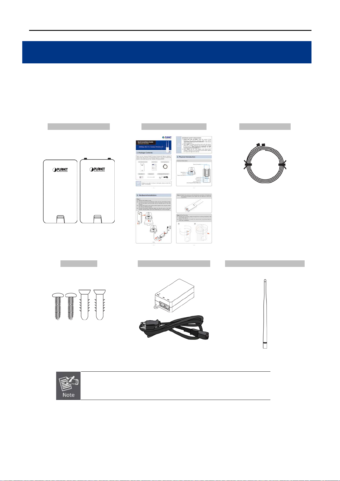
1.1 Package Contents
Thank you for choosing PLANET WAP-200N/WBS-200N series. Before installing the AP/CPE, please verify the
contents inside the packag e box.
WBS-200N / WAP-200N Quick Installation Guide Mounting Strap x 2
Screw Set x 1 PoE Injector & Power Cord Antenna x 2 (WAP-200N only)
If there is any item missing or damaged, please contact the seller
immediately.
-7-
User Manual of WAP-200N/WBS-200N
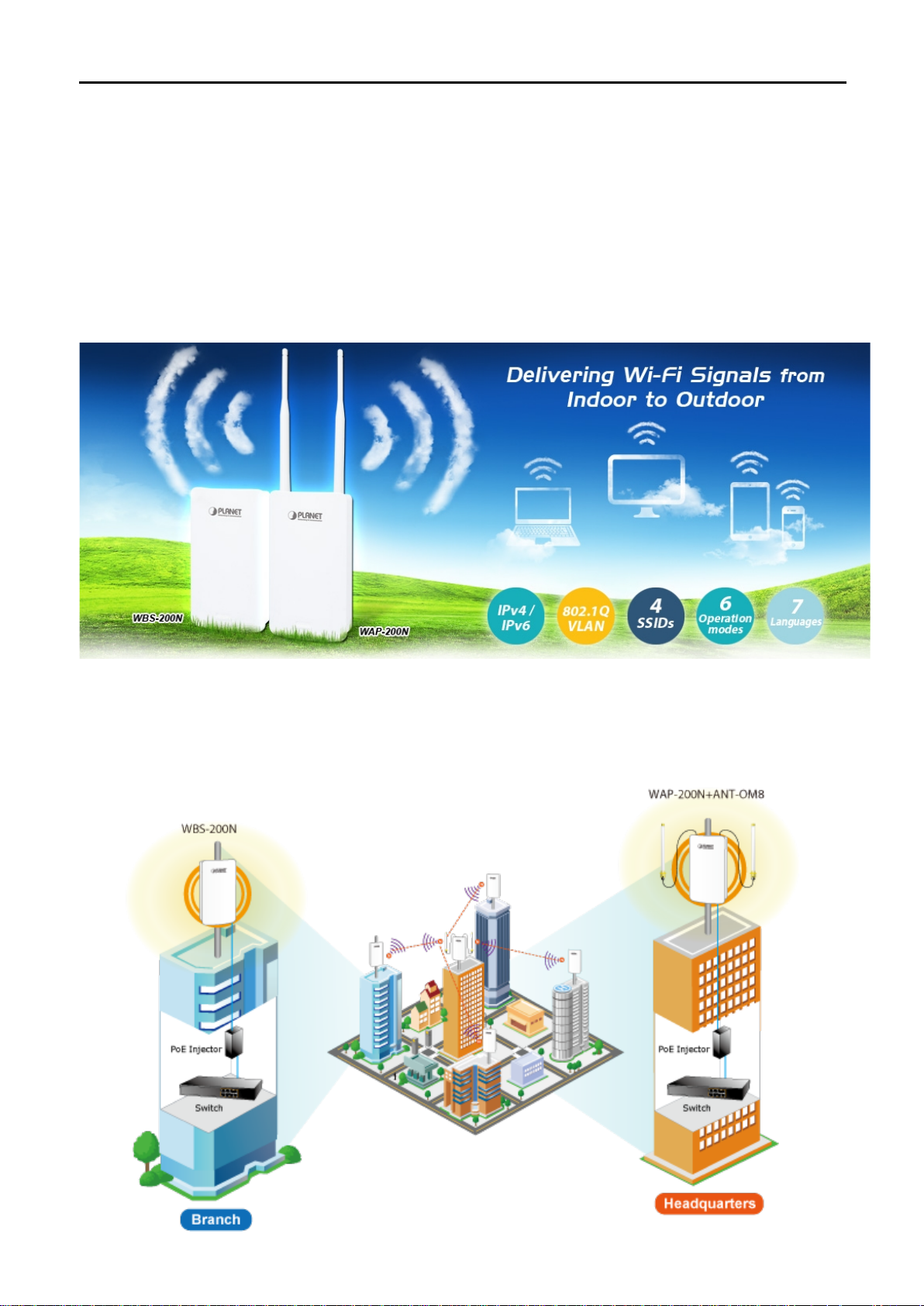
1.2 Product Description
Cost-effective Wireless Solution with Superior Performance
PLANET WAP-200N/WBS-200N 300Mbps 802.11n Outdoor Wireless AP/CPE offers a better range and
excellent throughput. Via the WAP-200N's RP-SMA antenna connectors and the WBS-200N's embedded 8dBi
dual-polarity directional antenna, it is easy to build different point to multi-point applications with good diversity
coverage and better noise immunity effect, thus heightening the performance and stability of a long-distance
connectivity.
Designed for Vari ous Req ui rements
The WAP-200N/WBS-200N is dedicatedly designed for WISP solution that provides CPE users with Internet
access via the WISP provider in rural areas. Besides, it caters to various wireless communication connectivities
(AP, Client, WDS, Repeater and WISP), thus meeting users’ application requirements.
-8-
User Manual of WAP-200N/WBS-200N
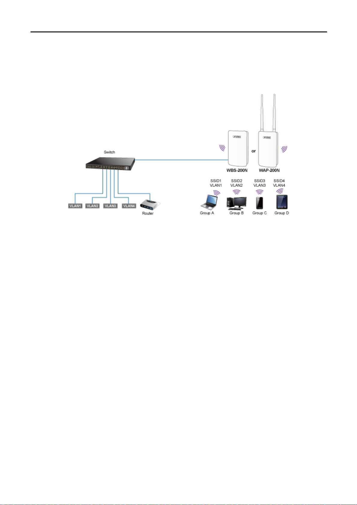
Multiple SSIDs with VLAN Tagging
Multiple SSIDs can broadcast up to four wireles s netw orks with di f ferent names. For ma nagement pur pose s, the
IEEE 802.1Q VLAN supported allows multiple VLAN tags to be mapped to multiple SSIDs to distinguish the
wireless access. This makes it possible for the WAP-200N/WBS-200N to work with managed Ethernet switches
to have VLANs assigned for a different access level and authority.
Flexible and Reliable Outdoor Characteristics
The WAP-200N/WBS-200N is definitely suitable for wireless IP sur veillanc e to enabl e to have wide deployments
between buildings and to act as the backbone of public service. Additionally, its self-healing capability keeps
connection alive all the time. With the IP55-rated outdoor UV-resistant enclosure, the WAP-200N/WBS-200N
can perform normally under rigorous weather conditions, meaning it can be installed in any harsh, outdoor
environments. With the proprietary Power over Ethernet (PoE) design, the WAP-200N/WBS-200N can be
easily installed in the areas where power outlets are not available.
Advanced Security and Rigorous Authen ti cation
The WAP-200N/WBS-200N supports 152-bit WEP, WPA/WPA2, WPA-PSK and WP A2-PSK wireless encryptions,
the advanced WPA2-AES mechanism and 802.1X RADIUS authentication, which can effectively prevent
eavesdropping by unauthorized users or bandwid th occupied by unauthenticated wireless access. Furthermore,
any users are granted or denied access to the wireless LAN network based on the ACL (Access Control List)
that the administrator pre-established.
Easy Deployment and Management
With user-friendly Web UI and comprehensive management features including client limit control and wireless
traffic shaping, the WAP-200N/WBS-200N is easy to limit the client access and inbound/outbound bandwidth
control, even for users who have no experience in setting up a wireless network. Furthermore, with the Planet
Smart Discovery Utility, SNMP and diagnostics tools, the WAP-200N/WBS-200N is convenient to be managed
remotely.
-9-

1.3 Product Features
Industrial Compliant Wireless LAN
Compliant with the IEEE 802.1 1 b/g/n wireless technology
2T2R architecture with data rate of up to 300Mbps
Equipped with two 10/100Mbps RJ45 ports, with auto MDI/MDI-X supported
Fixed Network Broadband Router
Supported WAN connection types in WISP mode: DHCP, Static IP, PPPoE, PPTP
Supports Port Forwarding and DMZ for various networking appli cat ions
Supports DHCP server in WISP mode
RF Interface Characteristics
Built-in 5dBi detachable antennas with RP-SMA connectors (WAP-200N)
Built-in 8dBi dual-polarization antenna (WBS-200N)
User Manual of WAP-200N/WBS-200N
High output power with multiply-adjustable transmit power control
Outdoor Environmental Characteristics
IP55 rating
Passive Power over Ethernet design
Operating temperature: -20~70°C
Multiple Operation Modes and Wireless Features
Multiple operation modes: AP, Client Bridge, Client Router (WIS P), WDS, Repeater
WMM (Wi-Fi multimedia) provides higher priority to multimedia transmitting over wireless
Wireless Traffic Shaping to control the upload/download bandwidth
Wi-Fi scheduler allows to be enabled or disabled based on predefined schedule
Secure Network Connection
Full encryption supported: 64-/128-/152-bit WEP, WPA/WPA2, WPA-PSK/WPA2-PSK and 802.1X
RADIUS authentication
Supports 802.1Q VLAN pass-through over WDS and SSID-to-VLAN mapping
Supports up to 50 entries of MAC address filtering
Easy Installation and Management
IPv4/IPv6 dual-stack management networks
Multilingual Web User Interface: English, Spanish, French, German, Portuguese, Russian, and
Simplified Chinese
CLI command and SNMP-based management interface
Self-healing mechanism through system auto reboot setting
System status monitoring through remote Syslog Server and Devic e Discovery
Diagnostic tools include Ping, Traceroute, Speed
Planet Smart Discovery Utility allows administrator to discover and locate each AP
-10-
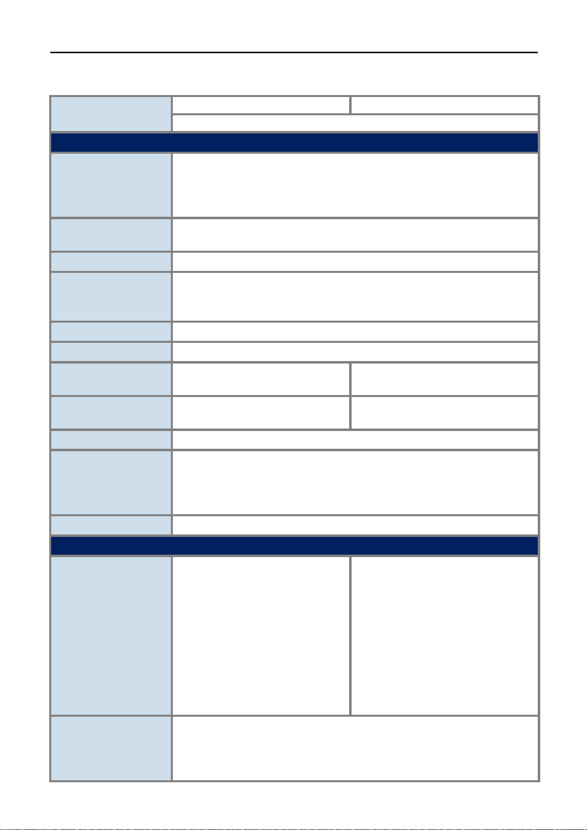
1.4 Product Specifications
WAP-200N
WBS-200N
SMA
in 8dBi directional antenna with dual
Product
2.4GHz 300Mbps 802.11n Outdoor Wireless AP/CPE
Hardware Features
IEEE802.11b/g/n
Standard Support
IEEE 802.3
IEEE 802.3u
IEEE 802.3x
User Manual of WAP-200N/WBS-200N
Memory
PoE
Interface
Button
LED
Dimensions (W x D x H)
Weight
Power Consumption
Power Requirements
64 Mbytes DDR SDRAM
16 Mbytes Flash
Passive PoE
Wireless IEEE 802.11b/g/n, 2T2R
PoE LAN (LAN 1): 1 x 10/100BASE-TX, auto-MDI/MDIX, 24V passive PoE In
LAN 2: 1 x 10/100BASE-TX, auto-MDI/MDIX
Reset button
PWR, LAN, WLAN, Signal Strength
100 x 29 x 186mm (without antennas)
100 x 29 x 380mm (with antennas)
300g (without antennas)
332g (with antennas)
100 x 29 x 186mm
300g
Maximum 7.2W
LAN1
24V DC, 0.6A (Passive PoE)
Pin 4, 5 V DC+
Pin 7, 8 V DC-
Mounting T y pe
Mast, wall mount
Wireless Interface Specifications
Built-in 5dBi detachable
omnidirectional antennas with RPconnectors
HPBW Horizontal: 360 degrees
Antenna
HPBW Ve rtical: 30 degrees
IEEE 802.11b: 1, 2, 5.5, 11Mbps
Data Rate
IEEE 802.11g: up to 54Mbps
IEEE 802.11n (20MHz): up to 150Mbps
IEEE 802.11n (40MHz): up to 300Mbps
Builtpolarization
[Port1]
HPBW Horizontal: 78 degrees
HPBW Ve rtical: 45 degrees
[Port2]
HPBW Horizontal: 54 degrees
HPBW Ve rtical: 59 degrees
-11-
User Manual of WAP-200N/WBS-200N
Media Access Control
Modulation
Frequency Band
Operating Channel
RF Output Power (dBm)
Receiver Sensitivity
(dBm)
CSMA/CA
Transmission/Emission type: OFDM
Data Modulation type: OFDM with BPSK, QPSK, 16-QAM, 64-QAM
2.412GHz ~ 2.472GHz
United States -- FCC: 2.414~2.462GHz (11 chan nels)
Europe -- ETSI: 2.412~2.472GHz (13 channels)
FCC: IEEE 802.11b/g/n: up to 26 ± 2dBm
ETSI: IEEE 802.11b/g/n: < 20dBm (EIRP)
IEEE 802.11b:
-95/ -93dBm (1~2/ 5.5~11Mbps)
IEEE 802.11g:
-95/ -93/ -92/ -80/ -77/ -75dBm (6/ 9~18/ 24/ 36/ 48/ 54Mbps)
IEEE 802.11n:
MCS0/ MCS8: -95dBm
MCS1/ MCS9: -93dBm
MCS2/ MCS10: -92dBm
MCS3/ MCS11: -90dBm
MCS4/ MCS12: -86dBm
MCS5/ MCS13: -83dBm
MCS6/ MCS14: -76dBm
MCS7/ MCS15: -73dBm
Environment & Certification
Operating Temperature
Operating Humidity
IP Level
Regulatory
-20~70 degrees C
10~90% (non-condensing)
IP55
CE, FCC, RoHS
Software Features
LAN
Supports 802.1d STP (Spanning Tree)
WAN Connection Type
(WISP Mode only)
Wireless Modes
Static IP
Dynamic IP
DHCP server in WISP mode
Static IP
Dynamic IP
PPPoE
PPTP
Access Point
Client Bridge
WDS (AP/Bridge/Station)
Client Router (WISP)/Client AP Router (WISP+AP)
Repeater
-12-

User Manual of WAP-200N/WBS-200N
Offers DoS protection to guard user's content network against DoS attac ks
Built-in DMZ and Port Forwarding
Firewall
Channel Width
Encryption Type
Wireless Security
Max. Wireless Client s
Max. SSIDs
Max. WDS Peers
Wireless QoS
Wireless Advanced
Control
VPN Pass-through:
PPTP Pass-through
L2TP Pass-through
IPSec Pass-through
20MHz/40MHz
64-/128-/152-bit WEP, WPA, WPA-PSK, WPA2, WPA2-PSK, 802.1X
Enable/Disable SSID Broadcast
Wireless MAC address filtering up to 50 entries
VAP Separation, Station Separation
Max. 64 (Suggested 32, depending on usage)
Up to 4
Up to 4
Supports Wi-Fi Multimedia (WMM)
Supports Wireless Traffic Shaping per Radio
Auto Channel Selection
Auto Tran smit Power by Regular Domains
Client Limit Control
Distance Control (Auto Ack Timeout)
Status Monitoring
VLAN
Self-healing
NTP
Management
Diagnostic Tools
Wi-Fi Schedule
Connection Status
Device Discovery, PLANET Smart Discovery
Wireless Client List/WDS Link List
DHCP Client Table
System Log supports remote syslog server
Signal Streng th LEDs in Client Bridge and WDS Station modes
VLAN pass-through over WDS
SSID-to-VLAN mapping
Management VLAN (VID: 1~4094)
Supports auto reboot settings
Network Time Management
Web-based UI, CLI (Command Line Interface) supported
Configuration backup and restore
SNMP v1/v2c/v3 support, MIB I/II, Private MIB
Built-in Ping, Trace Route, S peed Test Tools
-13-
User Manual of WAP-200N/WBS-200N
Chapter 2. Hardware Installation
2.1 Hardware Description
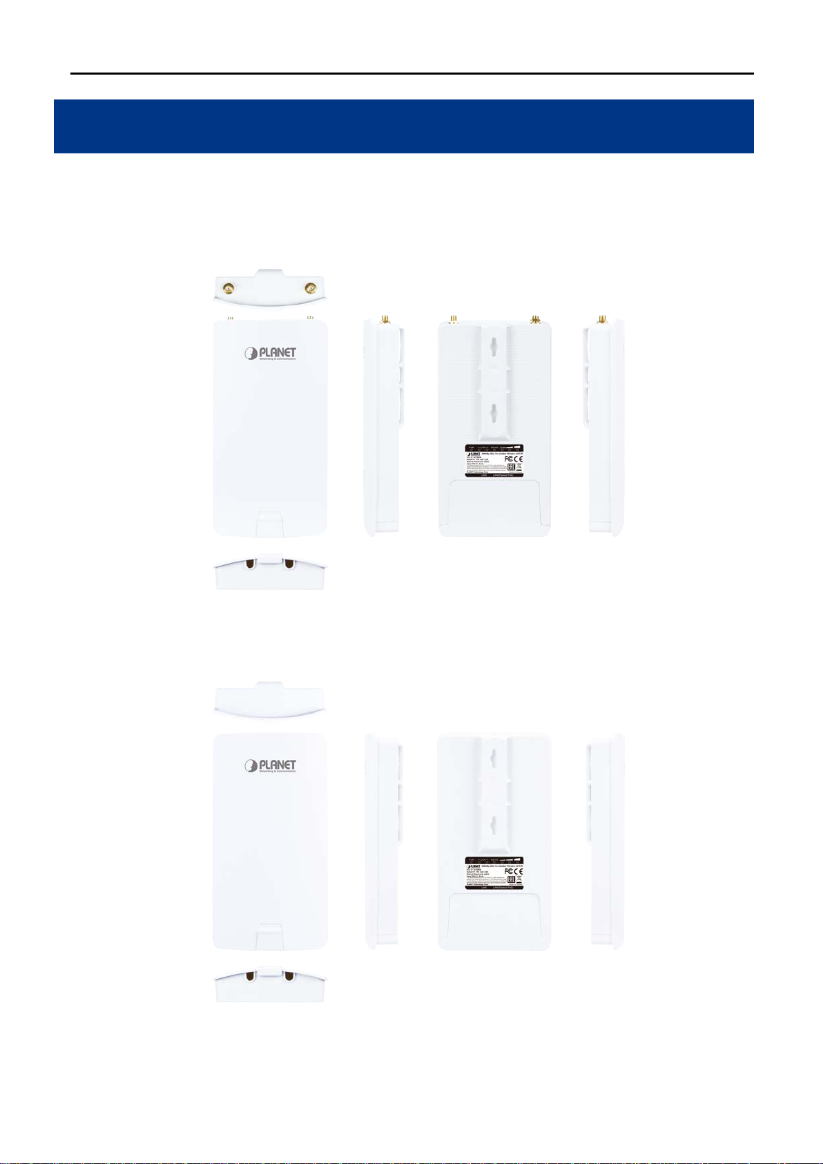
Dimensions (W x D x H): 100 x 29 x 186mm (without antennas)/100 x 29 x 380mm (with 5dBi antennas)
Figure 2-1 Three-way View (WAP-200N)
Figure 2-2 Three-way View (WBS-200N)
-14-
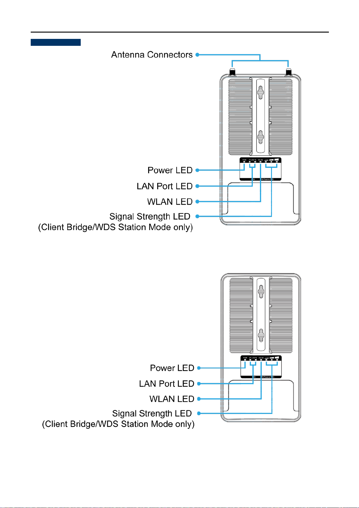
Rear Panel – LED
User Manual of WAP-200N/WBS-200N
Figure 2-3 Rear Panel (WAP-200N)
Figure 2-4 Rear Panel (WBS-200N)
-15-

LED Definition
LED State Meaning
On The device is powered on
Power
Off The device is powered off
On Port linked
User Manual of WAP-200N/WBS-200N
LAN Ports
Blinking Data is transmitting or receiving data
Off No link
On The wireless radio is on
WLAN
Blinking Data is transmitting or receiving over wireless
Off The wireless radio is off
Signal Strength
(Client Bridge/WDS
Green LED on
Orange LED on
Signal is good
Signal is normal
Station/Client Router
mode only)
Red LED on
Signal is poor
Table 2-1 The LED indication
2.1.1 The Bottom Panel
The Bottom panel provides the physical connectors connected to the power adapter and any other network
device. Figure 2-5 shows the bottom panel of the WAP-200N/WBS-200N.
-16-
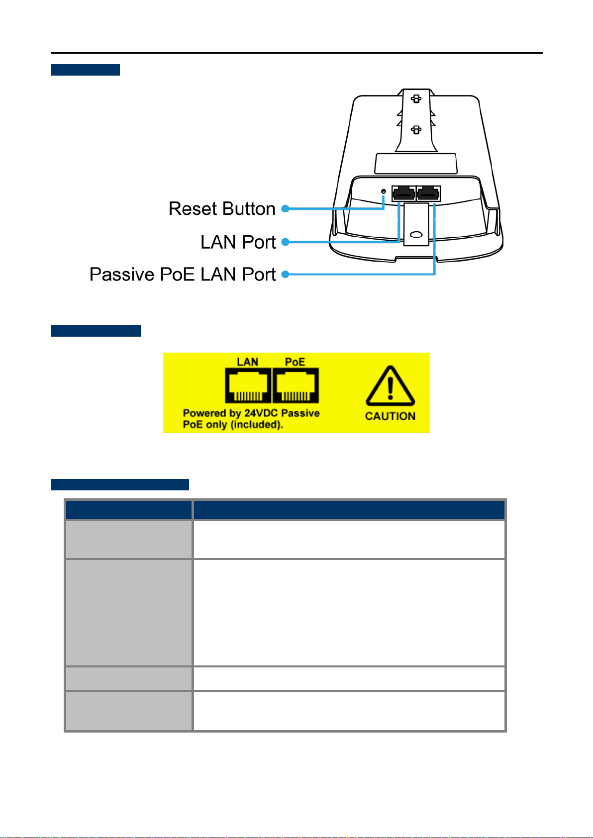
Bottom Panel
NOTE: Please use the 24V DC Passive PoE only (included)
PoE Warning Label
User Manual of WAP-200N/WBS-200N
Figure 2-5 Bottom Panel (WAP-200N/WBS-200N)
Hardware Interface Definition
Object Description
Antenna Connectors
2 RP-SMA (Fem al e) antenna connectors
(WAP-200N only)
10/100Mbps RJ45 port, auto MDI/MDI-X
Passive PoE/PD supported, 24V DC In
Passive PoE LAN Port
Pin assignment:
Pins 4, 5 (+)
Pins 7, 8 (-)
LAN Port
10/100Mbps RJ45 port, auto MDI/MDI-X
Press and hold the Reset button on the device for over 10 seconds
Reset Button
to return to the factory default setting.
Figure 2-6 PoE Warning Label
Table 2-2 Hardware Interface Definition
-17-

User Manual of WAP-200N/WBS-200N
Chapter 3. Connecting to the AP
3.1 Preparation before Installation
3.1.1 Professional Installation Required
Please seek assistance from a profes sional inst aller who is well trained in the RF inst allation and knowle dgeable
in the local regulations.
3.1.2 Safety Precautions
1. To keep you safe and install the hardware properly, please read and follow these safety precautions.
2. If you are installing the WBS-200N or WAP-200N for the first time, for your safety as well as others’,
please seek assistance from a professional installer who has received safety training on the hazards
involved.
3. Keep safety as well as performance in mind when selecting your installation site, especially where there
are electric power and phone lines.
4. When installing the WBS-200N or WAP-200N, please note the following things:
♦ Do not use a metal ladder;
♦ Do not work on a wet or windy day;
♦ Wear shoes with rubber soles and heels, rubber gloves, long sleeved shirt or ja cket.
5. When the system is operational, avoid st andin g directl y in front of it. Strong RF fields are present when the
transmitter is on.
3.2 Installation Precautions
Users MUST use a proper and well-installed surge arrestor and grounding kit with WBS-200N or
WAP-200N; otherwise, a random lightning could easily cause fatal damage to the WBS-200N or
WAP-200N. EMD (Lightning) DAMAGE IS NOT COVERED UNDER WARRANTY .
Users MUST use the “Power Cord and PoE Injector” shipped in the box with the WBS-200N or
WAP-200N. Use of other options will cause damage to the WBS-200N or WAP-200N.
-18-

User Manual of WAP-200N/WBS-200N
!
OUTDOOR INSTALLATION WARNING
IMPORTANT SAFETY PRECAUTIONS:
LIVES MAY BE AT RISK! Carefully observe these instructions and any special instructions that are included with the
equipment you are installing.
CONTACTING POWER LINES CAN BE LETHAL. Make sure no power
lines are anywhere where po ssible contact can b e made. A ntennas, mas ts,
towers, guy wires or cables may lean or fall and contact thes e li nes. Peo ple
may be injured or killed if they are touching or holding any part of equipment
when it contacts electric lines. Make sure th at equipment or personnel do
not come in contact directly or indirectly with power lines.
The horizontal distance from a t ower, mast or antenna to the nearest po wer
line should be at least twice the total length of the mast/antenna
combination. This will ensure that the mast will not contact po wer if it falls either during installati on or later.
TO AVOID FALLING, USE SAFE PROCEDURES WHEN WORKING AT HEIGHTS ABOVE GROUND.
Select equipment locations that will allow safe, simple equipment ins tall ation.
Don’t work alone. A friend or co-worker can save your life if an accident happens.
Use approved non-conducting lasers and other safety equipment. Make sure all equipment is in good repair.
If a tower or mast begins falling, don’t attempt to catch it. Stand back and let it fall.
If anything such as a wire or mast does come in contact with a power line, DON’T TOUCH IT OR ATTEMPT TO
MOVE IT. Instead, save your life by calling the power company.
Don’t attempt to erect antennas or t owers on windy days.
MAKE SURE ALL TOWERS AND MASTS ARE SECUREL Y GROUNDED, AND ELECTRICAL CABLES CONNECTED TO
ANTENNAS HAVE LIGHTNING ARRESTORS. This will help prevent fire damage or human injury in case of lightning, static
build-up, or short circuit within equipment connected to the antenna.
The base of the antenna mast or tower must be connected directly to the building protective ground or to one or more
approved grounding rods, using 1 OAWG ground wire and c orrosion-resistant connectors.
Refer to the National Electrical C ode for grounding details.
IF A PERSON COMES IN CONTACT WITH ELECTRICAL POWER, AND CANNOT MOVE:
DON’T TOUCH THAT PERSON, OR YOU MAY BE ELECTROCUTED.
Use a non-conductive dry board, stick or rope to push or drag them s o they no longer are in contact wit h electrical
power.
Once they are no longer contacting e lectrical power, administer CPR if you are cert ified, and make sure that emergency
medical aid has been requested.
-19-
User Manual of WAP-200N/WBS-200N
3.3 Installing the AP
Please install the AP according to the following steps. Don't forget to pull out the power plug and keep your
hands dry.
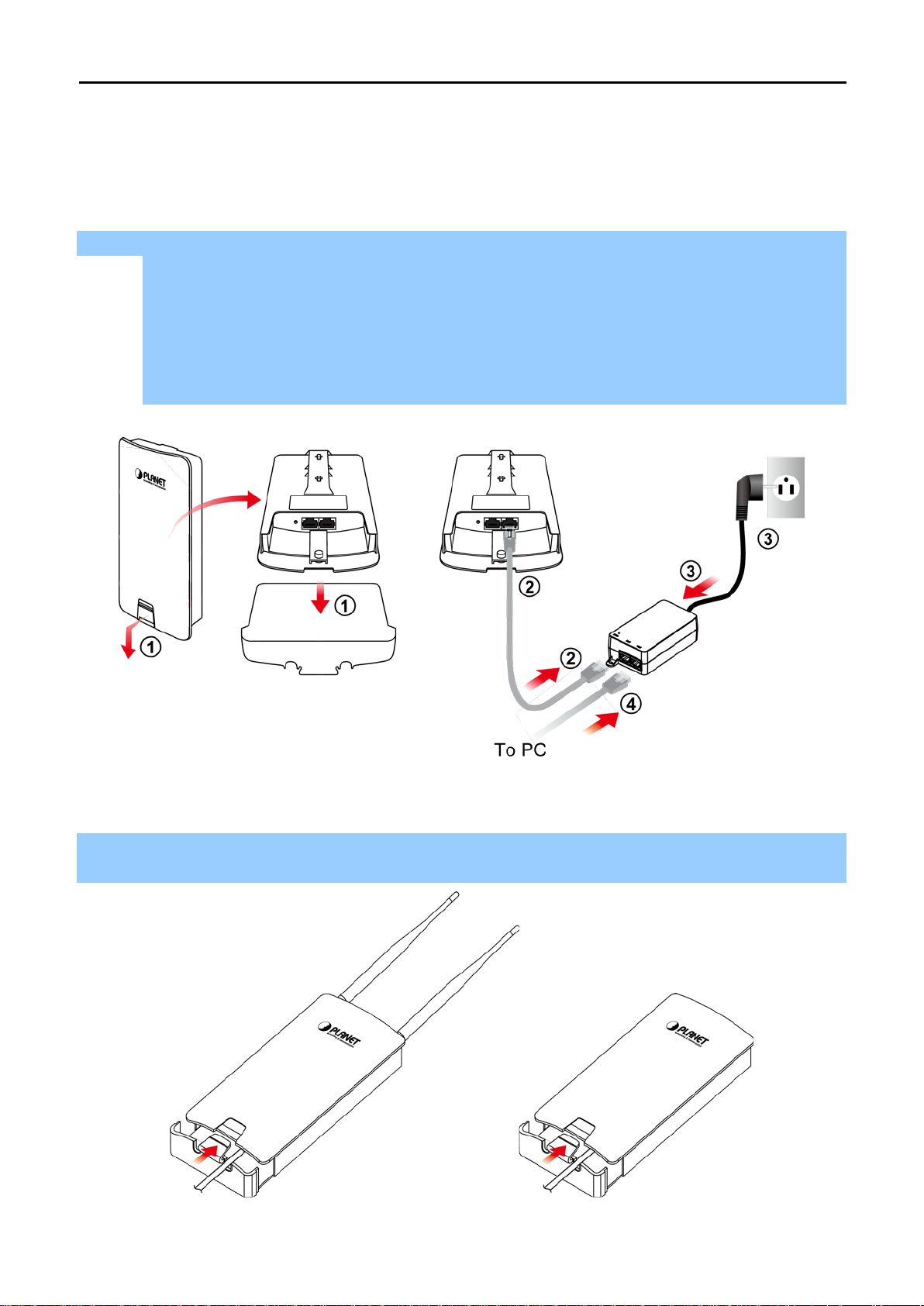
Step 1. PoE and LAN port connection:
(1) Remove the bottom cover.
(2) Connect one end of the Ethernet cable into the LA N (Passive PoE) port of the de vice and the other
end to the PoE port on the PoE Injector.
(3) Connect the power cord with the PoE Injector and pl ug the other end into an electrical outlet.
(4) Connect the second Ethernet cable into the LAN port of the PoE Injector and the other end to the
Ethernet port on the computer.
Figure 3-1 PoE and LAN port connection
Step 2. Attach the antennas onto the antenna connectors of the device and place the bottom cover back into
the device to finish the installation.
Figure 3-2 Finish installation and connect to antennas (WAP-200N only)
-20-
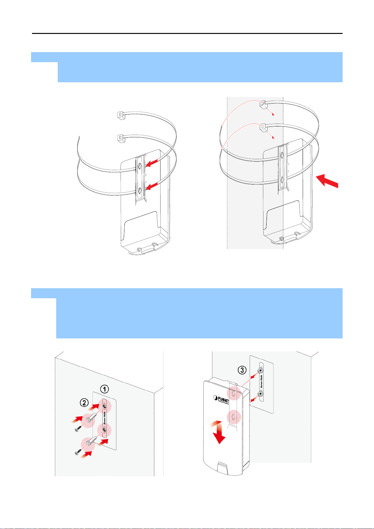
Step 3. Pole Mounting:
(1) Thread two mounting straps through the m ounting bracket on the back of the device.
(2) Position the device on a pole and secure both mounting straps to finish the installation.
User Manual of WAP-200N/WBS-200N
Step 4. Wall Mounting:
(1) Secure the adhesive label to a position on the wall where you would like to install the device.
(2) Follow the plotting sticker to drill two holes and secure the plastic anchors.
(3) Align the screw holes on the mounting bracket with the screws and then install the device on the
wall to finish the installation.
Figure 3-3 Pole Mounting
Figure 3-4 Wall Mounting
-21-

User Manual of WAP-200N/WBS-200N
time
Chapter 4. Quick Installation Guide
This chapter will show you how to configure the basic functions of your AP within minutes.
A computer with wired Ethernet connection to the Wireless AP is required for the firstconfiguration.
4.1 Manual Network Setup -- TCP/IP Configuration
The default IP address of the WBS-200N and WAP-200N is 192.168.1.253. And the default Subnet Mask is
255.255.255.0. These values can be changed as you desire. In this guide, we use all the default values for
description.
Connect the WBS-200N or WAP-200N with your PC via an Ethernet cable whi ch is then plugged into a LAN port
of the PoE injector with one end and into a LAN port of the PC with the other end. Then power on the WBS-200N
and WAP-200N via PoE injector or PoE switch.
In the following sections, w e’ll introdu ce how to instal l and configure the TCP/I P correctly in Windows 7. And the
procedures in other operating systems are similar. First, make sure your Ethernet adapter is working, and refer
to the Ethernet adapter’s manual if needed.
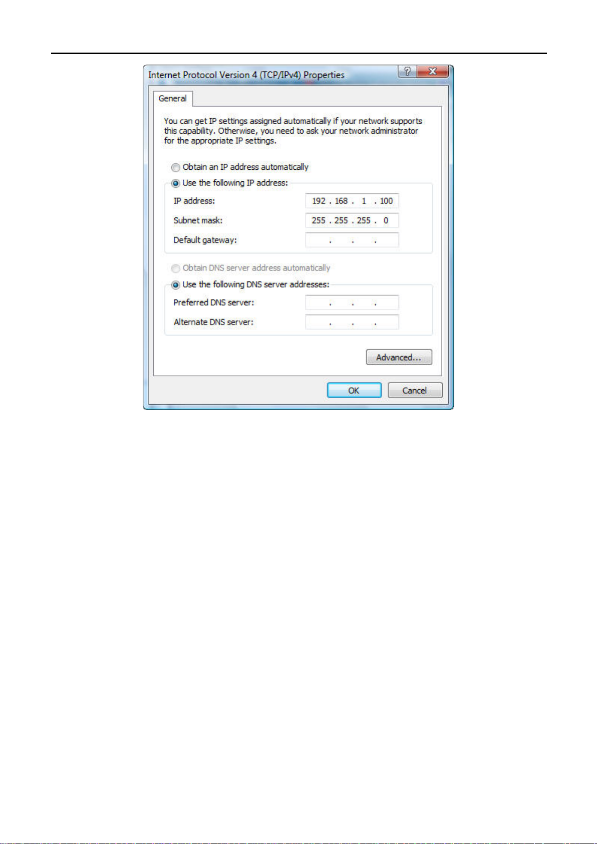
4.1.1 Configuring the IP Address Manually
Summary:
Set up the TCP/IP Protocol for your PC.
Configure the network parameters. The IP address is 192.168.1.xxx ("xxx" is any number from 2 to
252), Subnet Mask is 255.255.255.0.
1 Select Use the following IP address radio button.
2 If the AP's LAN IP address is 192.168.1.253, enter IP address 192.168.1.x (x is from 2 to 254 except
192.168.1.253), and Subnet mask is 255.255.255.0.
3 Select Use the following DNS server addresses radio button. In t he Preferred DNS Server field, you can
enter the DNS server IP address whi ch has been provided by your ISP
-22-
User Manual of WAP-200N/WBS-200N
Figure 4-1 TCP/IP Setting
Now click OK to save your settings.
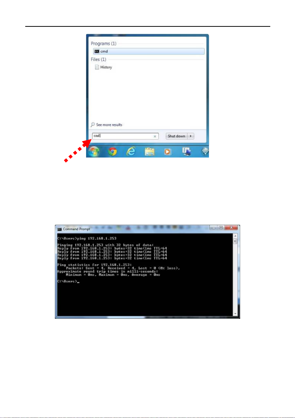
Now, you can run the ping command in the command prompt to verify the network connection between your
PC and the AP. The following example is in Windows 7 OS. Please follow the Steps below:
1. Click on Start > Run.
2. Type “cmd” in the Search box.
-23-
User Manual of WAP-200N/WBS-200N
Figure 4-2 Windows Start Menu
3. Open a command prom pt and type ping 192.168.1.253, and then pres s Enter.
If the result displayed is similar to Figure 4-3, it means the connection between your PC and the AP
has been established well.
Figure 4-3 Successful result of Ping command
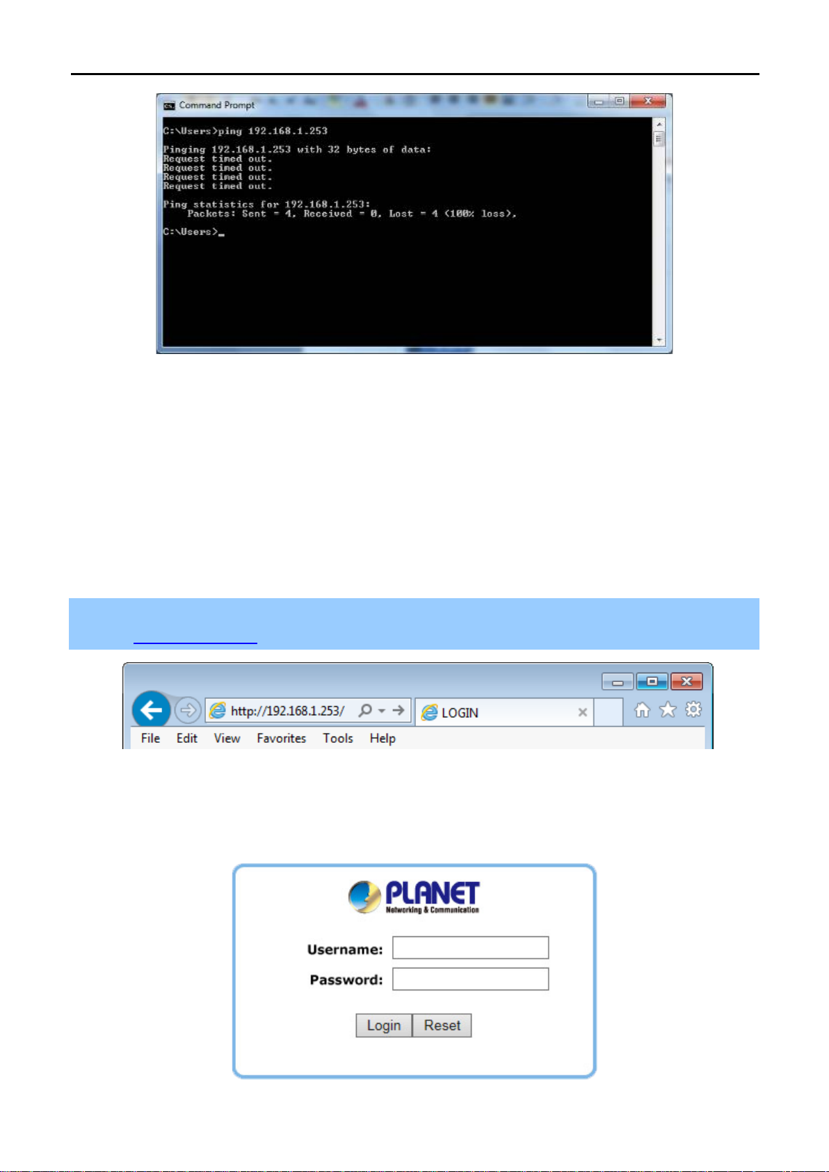
If the result displayed is similar to Figure 4-4, it means the connection between your PC and the AP
has failed.
-24-
User Manual of WAP-200N/WBS-200N
Figure 4-4 Failed result of Ping command
If the address is 0.0.0.0, check your adapter installation, security settings, and the settings on your AP. Some
firewall software programs may block a DHCP request on newly inst all ed adapters.
4.2 Starting Setup in the Web UI
It is easy to configure and manage the WBS-200N or WAP-200N with the web browser.
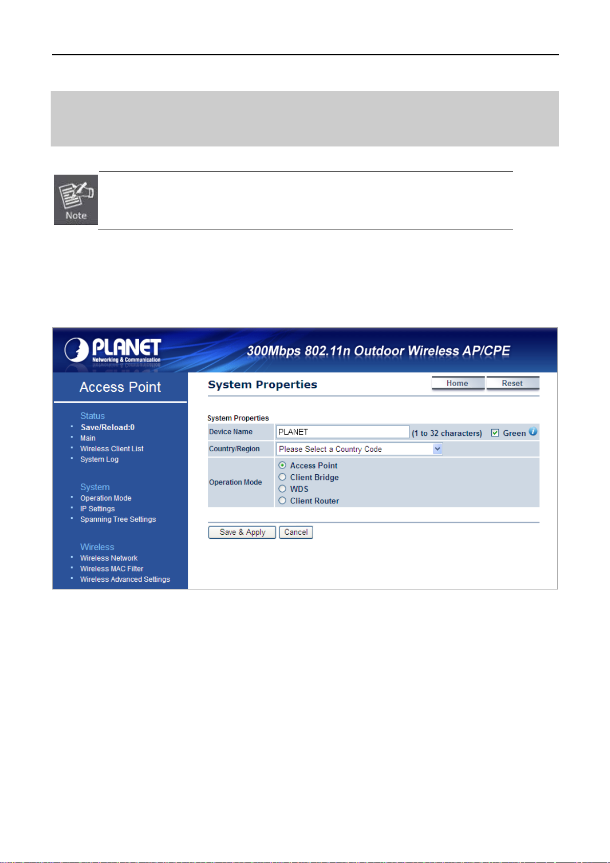
Step 1. To access the configuration page, open a web browser and enter the default IP address
http://192.168.1.253 in the web address field of the browser.
Figure 4-5 Login by default IP address
After a moment, a login window will appear. Enter admin for the User Name and Password, both in lower case
letters. Then click the OK button or press the Enter key.
Figure 4-6 Login Window
-25-
User Manual of WAP-200N/WBS-200N
Default IP Address: 192.168.1.253
Default User Name: admin
Default Password: admin
If the above screen does not pop up, it may mean that your web browser has been set to a
proxy. Go to Tools menu> Internet Options> Connections> LAN Settings in the screen
that appears, cancel the Using Proxy checkbox, and click OK to finish it.
After you enter into the Web User Interface, click Operation Mode at the left hand side of the screen to
configure the wireless connection. Once the basic configuration of the device is done, go to the Save/Reload
page to save and apply the changes.
Figure 4-7 Web UI Screenshot
You can choose an Operation Mode according to your application. Please refer to the instructions in the next
chapter for configuring different Operation Modes.
-26-

User Manual of WAP-200N/WBS-200N
The advantage of WDS is the Layer 2 transparent
all connected
standard extension to the IEEE 802.11
standard, which implemented differently in wireless driver and firmware
making them incompatible with each other. In order to use WDS, the same
model of devices should be used.
can connect to a wireless
the wireless coverage with same SSID and
Chapter 5. Configuring the AP
This chapter instructs you how to quickly configure the AP/CPE in different operation modes.
5.1 Operation Mode
On this page, you can select different operation modes of the AP depending on your application, including:
Operation Modes
Access Point
Client Bridge
WDS Access Point
WDS Bridge
Description
Access Point mode is used to provide wireless connectiv it y to wireless clients. This
mode is compatible with general wireless clients.
Client Bridge mode allows the Access Point to become a wirel ess client to associat e
to another AP thus enabling the wireless capabi l i ty of wired clients.
In WDS Access Point mode, the device functions as a WDS bridge with Access
Point Mode. For WDS Access Point, it can be connected by same series of devices
which using the WDS station mode. In this mode, the setting is same as Access
Point Mode.
In WDS Bridge mode, the device can bridge with remote LAN networks through
MAC address. This application can create two individual networks for two groups of
users sharing one Internet.
bridging and broadcasting across wireless connections so that
network devices form one common broadcast domain.
NOTE: The WDS mode is a non-
WDS Station
Client Router
Repeater
Go to “System Operation Mode” page to configure the device in the operation mode which is suitable for
your application. Then go to “Wireless
mode.
In WDS Station mode, the device functions as a wireless client which can bridge t he
remote WDS Access Point with SSID. In this mode, the setting is same as Client
Bridge mode.
With Client Router (Wireless ISP) mode, the device
network and share the Internet connection to the WISP subscribers.
On the LAN side, the device acts like a wired router for IP sharing function. In this
mode, the wireless interface acts as WAN side.
Repeater mode is used to extend
security.
Wireless Network” to configure the related wireless settings of each
-27-
User Manual of WAP-200N/WBS-200N
Disable the green option to enable transmit power to be configured
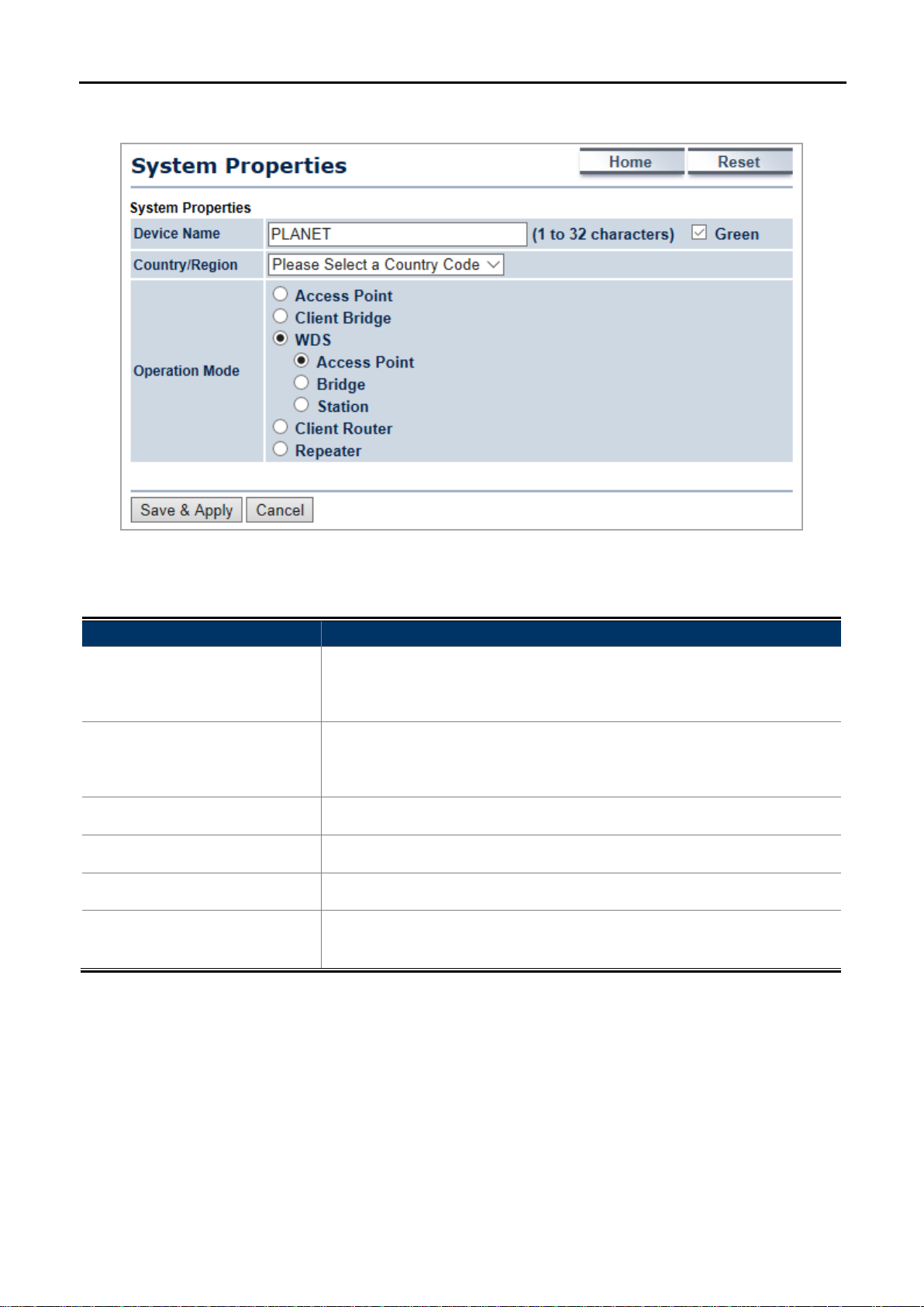
Figure 5-1 Operation Mode – All
The page includes the following settings:
Object Description
Enter a name for the device (1-32 characters). The name you type
• Device Name
appears in SNMP management. This name is not the SSID and is not
broadcast to other devices.
• Green
manually. Keep it as default setting t o prevent violating regional regulation
unless your configuration meets the regulation.
• Country/Region
• Operation Mode
• Save & Apply
Select a Country/Region to conform to local regulations.
Use the radio button to select an operation mode.
Click Save & Apply to save changes.
Click Cancel to cancel the unsaved changes and revert to t he previous
• Cancel
settings.
-28-
User Manual of WAP-200N/WBS-200N
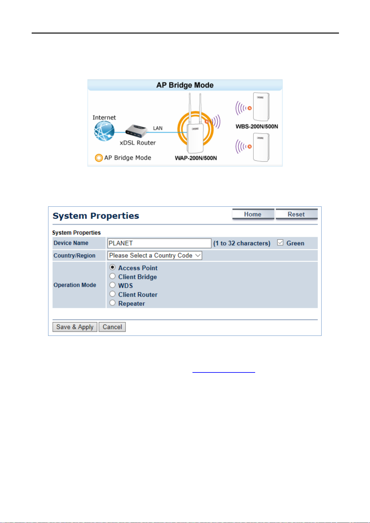
5.1.1 Access Point (AP)
This section allows you to configure the AP Bridge mode to provide wireless connectivity for wireless clients.
Go to the “System Operation Mode” page to configure the device as “Access Point” and then go to
“Wireless
Wireless Network” to configure the related wireless settings.
Figure 5-2 Operation Mode – AP
For the configuration example, please refer to the section “
Appendix C: FAQ, Q1”.
-29-
 Loading...