

Page 1

802.11g Wireless LAN Outdoor CPE AP
WAP-6100
User’s Manual
Version 2.0
Page 2

Copyright
Copyright © 2008 by PLANET Technology Corp. All rights reserved. No part of this publication may
be reproduced, transmitted, transcribed, stored in a retrieval system, or translated into any language
or computer language, in any form or by any means, electronic, mechanical, magnetic, optical,
chemical, manual or otherwise, without the prior written permission of PLANET.
PLANET makes no representations or warranties, either expressed or implied, with respect to the
contents hereof and specifically disclaims any warranties, merchantability or fitness for any particular
purpose. Any software described in this manual is sold or licensed "as i s". Should the programs
prove defective following their purchase, the buyer (and not this company, its distributor, or its dealer)
assumes the entire cost of all necessary servicing, repair, and any incidental or consequential
damages resulting from any defect in the software. Further, this company reserves the right to revise
this publication and to make changes from time to time in the conte nts hereof without obligation to
notify any person of such revision or changes..
All brand and product names mentioned in this manual are trademarks and/or register ed trademarks
of their respective holders.
FCC Caution:
To assure continued compliance.(example-use only shielded interface cables when connecting to
computer or peripheral devices). Any changes or modifications not expressly approved by the party
responsible for compliance could void the user’s authority to operate the equipment.
This device complies with Part 15 of the FCC Rules. Operation is subject to the Following two
conditions: (1) This device may not cause harmful interference, and (2) this Device must accept any
interference received, including interference that may cause undesired operation.
Federal Communication Commission (FCC) Radiation Exposure
Statement
This equipment complies with FCC radiation exposure set forth for an uncontrol led environment. In
order to avoid the possibility of exceeding the F CC radio frequency expos ure limits, human proximit y
to the antenna shall not be less than 20cm (8 inches) during normal operation.
CE Mark Warning
This is a Class B product. In a domestic environment, this product may cause radio interference, in
which case the user may be required to take adequate measures.
Protection requirements for health and safety – Article 3.1a
Testing for electric safety according to EN 60950 has been conducted. These are considered relevant
and sufficient.
Protection requirements for electromagnetic compatibility – Article 3.1b
Testing for electromagnetic compatibility accordi ng to EN 301 489-1, EN 301 489-17 and EN 55 024
has been conducted. These are considered relevant and sufficient.
Page 3

Effective use of the radio spectrum – Article 3.2
Testing for radio test suites according to EN 300 328-2 ha s been conducted. These are considered
relevant and sufficient.
CE in which Countries where the product may be used freely:
Germany, UK, Italy, Spain, Belgium, Netherlands, Portugal, Greece, Irela nd, Denmark, Luxembourg,
Austria, Finland, Sweden, Norway and Iceland.
France: except the channel 10 through 13, law prohibits the use of other channels
Safety
This equipment is designed with the utmost care for the safety of those who install and use it. However,
special attention must be paid to the dangers of electric shock and static electricity when working with
electrical equipment. All guidelines of this and of the computer manufacture must therefore be allowed
at all times to ensure the safe use of the equipment.
WEEE regulation
To avoid the potential effects on the environment and human health as a result of
the presence of hazardous substances in electrical and electronic equipment, end
users of electrical and electronic equipment should understand the meaning of the
crossed-out wheeled bin symbol. Do not dispose of WEEE as unsorted municipal
waste and have to collect such WEEE separately.
Revision
User’s Manual for PLANET 802.11g WLAN Outdoor CPE AP
Model: WAP-6100
Rev: 2.0 (October, 2008)
Part No. EM-WAP6100
Page 4

TABLE OF CONTENTS
CHAPTER 1 INTRODUCTION...........................................................................................................6
1.1 PACKAGE CONTENTS ......................................................................................................................6
1.2 FEATURES .......................................................................................................................................6
1.3 SPECIFICATION................................................................................................................................7
1.4 LED INDICATORS............................................................................................................................8
1.5 WIRELESS PERFORMANCE ..............................................................................................................9
CHAPTER 2 HARDWARE INSTALLATION..................................................................................10
CHAPTER 3 INITIAL SETUP ...........................................................................................................13
3.1 SETUP PROCEDURES .....................................................................................................................13
CHAPTER 4 WEB CONFIGURATION............................................................................................15
4.1 ACCESS POINT MODE....................................................................................................................15
4.1.1 System Summary..................................................................................................................15
4.1.2 W ireless Station List.............................................................................................................16
4.1.3 System Properties.................................................................................................................17
4.1.4 Administration...................................................................................................................... 18
4.1.5 IP Settings............................................................................................................................19
4.1.6 W ireless Network..................................................................................................................19
4.1.7 W ireless Security..................................................................................................................20
4.1.8 W ireless Advanced Settings..................................................................................................24
4.1.9 SNMP..............................................................................................................................26
4.1.10 MAC Filter.................................................................................................................26
4.1.11 Backup / Restore Settings...................................................................................................27
4.1.12 Firmware Upgrade.............................................................................................................27
4.1.13 Reboot................................................................................................................................28
4.2 WIRELESS CLIENT MODE..............................................................................................................29
4.2.1 Connection Status ................................................................................................................30
4.2.2 W ireless Network..................................................................................................................31
4.2.3 W ireless Security..................................................................................................................32
4.2.4 Ethernet Client List..............................................................................................................33
4.3 REPEATER MODE .......................................................................................................................... 34
4.3.1 W ireless Network..................................................................................................................34
4.3.2 W ireless Security..................................................................................................................35
4.4 WIRELESS BRIDGE........................................................................................................................36
4.4.1 WDS Link Settings................................................................................................................36
4.4.2 WDS Security Settings..........................................................................................................37
Page 5

APPENDIX A GLOSSARY...................................................................................................................1
APPENDIX B GLOSSARY...................................................................................................................1
Page 6

Chapter 1 Introduction
The WAP-6100 is an outdoor 802.11g CPE AP with 12dBi antenna built in. This manual describes the
details of how to manage this equipment.
1.1 Package Contents
Make sure that you have the following items:
• One WAP-6100
• One Power Cord
• One PoE Injector
• One Metal Ring
• One 25m CAT5 Cable with RJ-45 plug and ODU connector
• One 1.9m CAT5 Cable with RJ-45 plugs
• One User’s Manual and Utility CD
• One Quick Installation Guide
Note:
If any of the above items are missing, contact your supplier as soon as
possible.
1.2 Features
‧ Wireless LAN IEEE802.11b/g compliant
‧ Solid housing provides protection against rigorous weather conditions
‧ Four operating modes support: AP, Wireless Bridge, Wireless Client, and Repeater
‧ Strong network security with 64/128/152-bit WEP encryption, WPA and WPA-PSK
‧ Built-in 12dBi patch antenna
‧ 5 levels of adjustable transmit power control
‧ Super G mode raises the data rate up to 108Mbps
‧ Support DHCP Client
‧ Provides “Connection Status” indication for Repeater and Client modes
‧ Power over Ethernet design
Page 7

1.3 Specification
Model WAP-6100
Standard IEEE 802.11b, 802.11g
Signal Type DSSS (Direct Sequ ence Spread Spectrum)
Modulation OFDM with BPSK, QPSK, 16QAM, 64QAM, DBPSK, DQPSK, CCK
Port 10/100Mbps RJ-45 port * 1
Antenna Built-in 12dBi patch antenna
Output Power 18dBm@11Mbps / 17dBm@54Mbps (typical)
5 levels adjustable (Full, Half, Quarter, Eighth, Minimum)
Sensitivity
-74dBm@54Mbps OFDM, 10% PER
-88dBm@11Mbps CCK, 8% PER
Operating Mode AP, Wireless Bridge, Wireless Client, Repeater
WEP setting
− Authentication type: Open System / Shared Key
− Shared keys input type: HEX / ASCII
− Shared keys length: (64-bit, 128-bit, 152-bit)
− Default WEP Key to use (1-4)
WPA-PSK setting
Security
− PassPhrase
− WPA Cipher Type (TKIP, AES)
− Group Key Update Interval: 300
WPA setting
− Radius Server IP Address
− Radius Port: 1812
− WPA Cipher Type (TKIP, AES)
− Shared Key
Group Key Update Interval: 300
Super G mode Up to 108Mbps
Data Rate
802.11g
802.11b Up to 11Mbps (1/2/5.5/11)
Dimensions (L x W x H) 185 x 106 x 62mm
Weight 400g
Operating temperature: -10 – 70 degree C
Environmental
Storage temperature: -30 – 80 degree C
Specification
Relative humanity: 0% – 90% (non-condensing)
Up to 54Mbps (6/9/12/18/24/36/48/54)
Page 8
Power Requirement 48V DC, 0.4A
Electromagnetic
Compatibility
FCC, CE
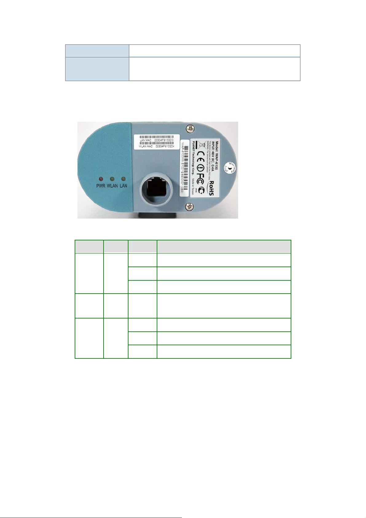
1.4 LED Indicators
WAP-6100v2 LED Indicators
LED Color Status Description
On Device power on
PWR Red
WLAN Green Blinking
LAN Green
Off Device power off
Blinking During boot up procedure
Transmitting or receiving data through the Wireless
LAN
On Link is established
Blinking Packets are transmitting or receiving
Off LAN port is not connected
Page 9

1.5 Wireless Performance
The following information will help you utilizing the wireless performance, and operating coverage of
WAP-6100.
1. Site selection
To avoid interferences, please locate WAP-6100 and wireless clients away from transformers,
microwave ovens, heavy-duty motors, refrigerators, fluorescent lights, and other industrial
equipments. Keep the number of walls, or ceilings between AP and clients as few as possible;
otherwise the signal strength may be seriously reduced. Place WAP-6100 in open space or add
additional WAP-6100 as needed to improve the coverage.
2. Environmental factors
The wireless network is easily affected by many environmental factors. Every environment is
unique with different obstacles, construction materials, weather, etc. It is hard to determine the
exact operating range of WAP-6100 in a specific location without testing.
Page 10
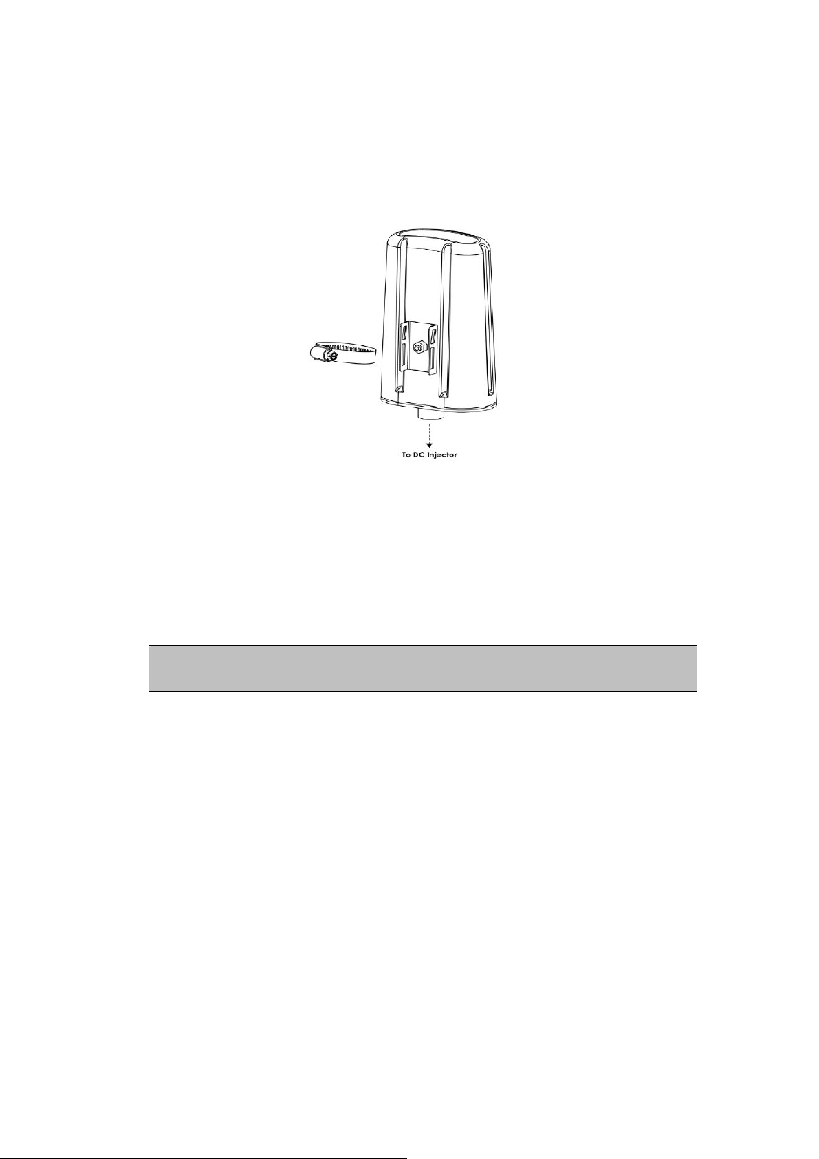
Chapter 2 Hardware Installation
Before you proceed with the installation, it is necessary t hat you have enough information about the
WAP-6100.
1. Locate an optimum location and use the provided metal ring to secure WAP-6100 to a mast.
2. Using provided CAT5 waterproof cable; connect the waterproof connector port of the WAP-6100
to the “P+DATA OUT” port of PoE Injector.
3. Using Category 3 or higher UTP or STP cable, connect the “DATA IN” port of PoE Injector to a
10Mbps or 10/100Mbps Ethernet hub or switch, and connect the management station to a hub or
switch on the same LAN.
4. Connect the power cord to the PoE Injector, and plug it into an AC outlet to power up the
WAP-6100.
Note: ONLY use the power adapter supplied with the WAP-6100. Otherwise, the product may be
damaged.
Page 11

OUTDOOR INSTALLATION WARNING
!
IMPORTANT SAFETY PRECAUTIONS:
LIVES MAY BE AT RISK! Carefully observe these instructions and any special instructions that are
included with the equipment you are installing.
CONTACTING POWER LINES CAN BE LETHAL. Make sure no power lines are anywhere where
possible contact can be made. Antennas, masts, towers,
guy wires or cables may lean or fall and contact these
limes. People may be injured or killed if they are touching
or holding any part of equipment when it contacts electric
lines. Make sure there is NO possibility that equipment or
personnel can come in contact directly or indirectly with
power lines.
Assume all overhead lines are power lines.
The horizontal distance from a tower, mast or antenna to the nearest power line should be at least twice
the total length of the mast/antenna combination. This will ensure that the mast will not contact power if it
falls either during installation or later.
TO AVOID FALLING, USE SAFE PROCEDURES WHEN WORKING AT HEIGHTS ABOVE GROUND.
z Select equipment locations that will allow safe, simple equipment installation.
z Don’t work alone. A friend or co-worker can save your life if an accident happens.
z Use approved non-conducting lasers and other safety equipment. Make sure all equipment is in
good repair.
z If a tower or mast begins falling, don’t attempt to catch it. Stand back and let it fall.
z If anything such as a wire or mast does come in contact with a power line, DON’T TOUCH IT
OR ATTEMPT TO MOVE IT. Instead, save your life by calling the power company.
z Don’t attempt to erect antennas or towers on windy days.
MAKE SURE ALL TOWERS AND MASTS ARE SECURELY GROUNDED, AND ELECTRICAL
CABLES CONNECTED TO ANTENNAS HAVE LIGHTNING ARRESTORS. This will help prevent fire
damage or human injury in case of lightning, static build-up, or short circuit within equipment connected
to the antenna.
Page 12

z The base of the antenna mast or tower must be connected directly to the building protective
ground or to one or more approved grounding rods, using 1 OAWG ground wire and
corrosion-resistant connectors.
z Refer to the National Electrical Code for grounding details.
IF A PERSON COMES IN CONTACT WITH ELECTRICAL POWER, AND CANNOT MOVE:
z DON’T TOUCH THAT PERSON, OR YOU MAY BE ELECTROCUTED.
z Use a non-conductive dry board, stick or rope to push or drag them so they no longer are in
contact with electrical power.
Once they are no longer contacting electrical power, administer CPR if you are certified, and make sure
that emergency medical aid has been requested.
Page 13
Chapter 3 Initial Setup
The WAP-6100 allows configuration either via the configuration utility, known as Locator, or Web Browser
through network. For the initial installation, we suggest using the PLANET WAP-6100 Locator. Before
using Locator, please make sure the personal firewall installed in your PC is disabled.
It is strongly recommended to configure and manage WAP-6100 using a wired LAN computer.
3.1 Setup Procedures
1. Insert the bundled CD in the CD-ROM drive to initiate the autorun program. Click on the
"PLANET WAP-6100 Locator" hyperlink to activate the program.
Or you can start the installation as follows.
A. Click on Start Menu/ Run.
B. Enter “E:\UTILITY\Locator.exe” in the appeared box, where “E” is the letter of your CD-ROM
drive.
C. Click on “OK” button.
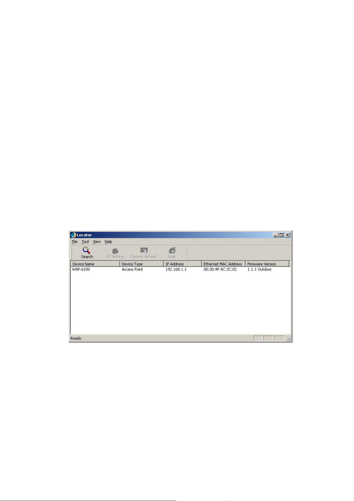
2. When the Loc ator is started, it will search the available WAP-6100 on the same network. The
Locator shows you the Device Name, Device Type, IP Address, Ethernet MAC Address and
Firmware Version. If there are multiple WAP-6100 or WAP-6100 in the same network, all of
them will be listed.
3. To change the IP address, select the target WAP-6100 if there are multiple devices, and click on
the “IP Setting” button. A login dialog box will pop up. Please input your user name and
password into the fields. Default user name and password are as below:
User Name: Admin
Password: (blank)
Please note the first character of user name is a capital letter.
Page 14
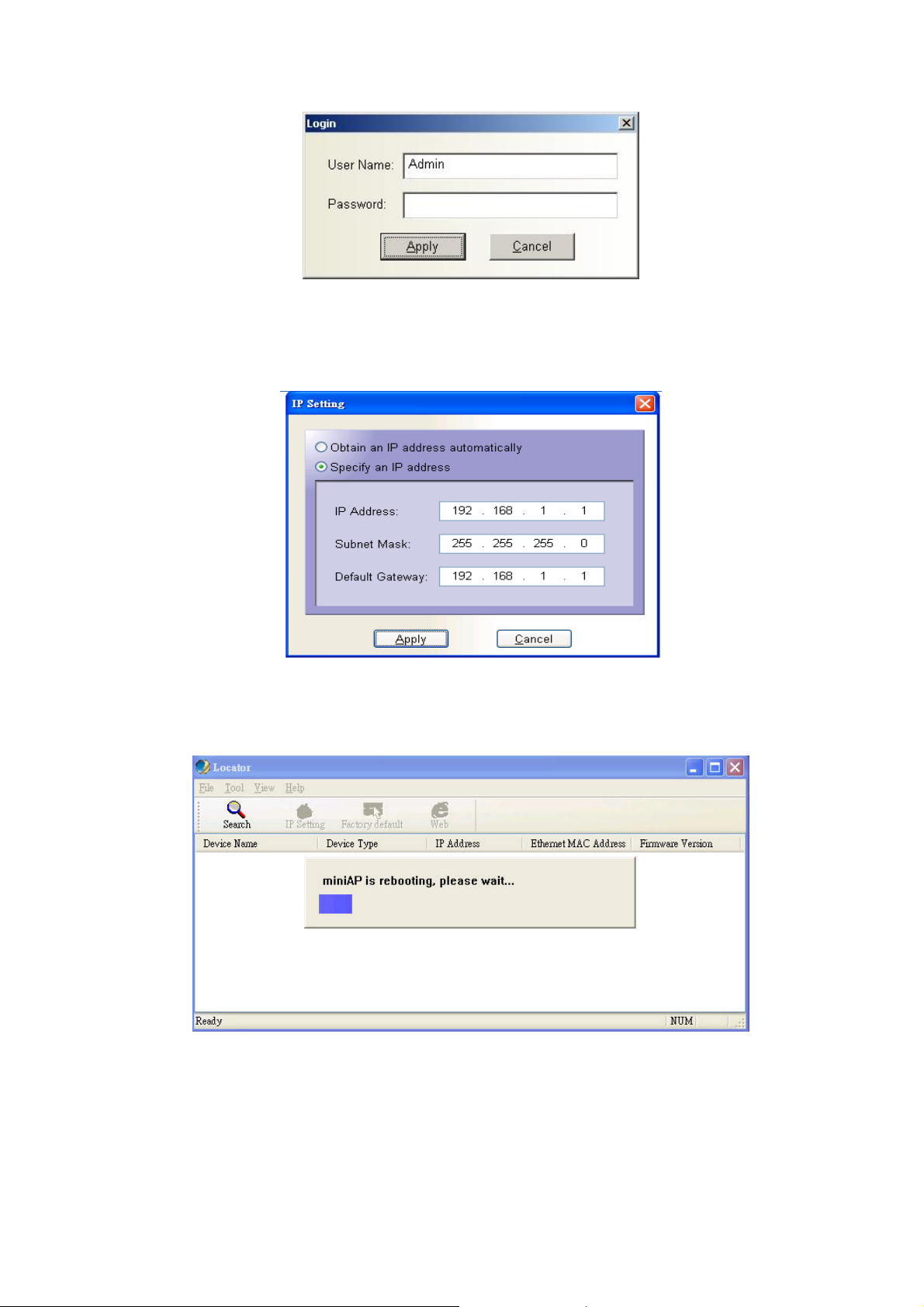
4. After type in correct user name and password, the “IP Setting” box appears. Here you can
choose to obtain IP from a DHCP server or specify IP address manually. If your environment or
ISP provide DHCP server, you can choose the first option. Other wise, you need to manually
setup IP address. Click on “Apply” button and WAP-6100 will reboot immediately. After the
reboot completes, the WAP-6100 is operating with new settings.
5. To restore WAP-6100 back to factory default values, click on the “Factory default” icon. This
operation requires you to login the WAP-6100 first. Please input correct user name and password
into the fields. The WAP-6100 will reboot immediately. After the reboot completes, the WAP-6100 is
operating with default settings.
6. Click on the “Web” icon, the Internet Explorer will be executed and connect to the web interface
of WAP-6100. Please refer to the next chapter for how to manage WAP-6100 via web.
Page 15

Chapter 4 Web Configuration
Web configuration provides a user-friendly graphical user interface (web pages) to manage your
WAP-6100. An AP with an assigned IP address (e.g. http://192.168.1.1) will allow you to monitor and
configure via web browser (e.g., MS Internet Explorer or Netscape).
1. Open your web browser.
2. Enter the IP address of your WAP-6100 in the address field (default IP address is http://192.168.1.1
Please note that your PC’s IP address should be on the same IP subnet of the WAP-6100. For
example, you can configure your PC’s IP address to 192.168.1.2 if WAP-6100 is with IP 192.168.1.1.
3. A User Name and Password dialog box will appear. Please enter your User Name and Password here.
Default User Name and Password are as below:
User Name: Admin
Password: (blank)
Please note the first character of user name is a capital letter.
4. T hen you will see the WAP-6100 web configuration page after click on “OK”.
).
4.1 Access Point Mode
4.1.1 System Summary
System Information
• This will display system name and both Ethernet MAC address and Wireless MAC
address. Current country setting and firmware version will also be available here.
Current IP Settings
• This section shows current IP address setting including IP address, Subnet Mask, Default
Gateway and DHCP status.
Page 16

Current Wireless Settings
• This area shows current wireless setting including operation mode, wireless mode, SSID,
channel and security setting.
4.1.2 Wireless Station List
This page can help user identify current clients who already associated to the WAP-6100. You can also
click on the MAC address column then the system will show the detail technical information for each
wireless station.
The page below describes the detail connection information with each station. You can get all information
needed right here.
Page 17

4.1.3 System Properties
Device Name
Country / Region
You may assign any name to the WAP-6100. Memorable, Unique names are
helpful especially if you are employing multiple acc ess points on the same
network. The device name needs to be less than 32 characters. After verify
the name you input and click “Apply” to save the setting.
Here you can set the WAP-6100 to follow different country and region
regulations.
Page 18

Operation Mode
The default operation mode is Access Point; this mode connects your
wireless clients to a wired network. In most cases, no change is necessary.
You can switch operation mode to Wireless Client, Repeater or Wireless
Bridge mode depends on your application. Wireless Cl ient mode can allow
AP act as a client within its range. Your Ethernet devices behind the AP client
can connect to a remote AP. Repeater is able to retransmit the signal of a
remote AP. Choose repeater mode if you want to extend the range of your
original AP. Wireless Bridge mode allow you to create a wireless connection
to connect the networks between different building. You may check to the
section 4.2/4.3 and 4.4 for more details of those operating mode.
4.1.4 Administration
Administrator Name
Password
Confirm Password
You change the administrator login name i n this field.
Type the new password here if you need to change it.
Re-type the new password again, then click the “Apply” below to save the
changes.
Page 19

4.1.5 IP Settings
This page can configure system IP address. Default IP address is 192.168.1.1 and Subnet Mask is
255.255.255.0. You can manually input IP address setting or get an IP from a DHCP server.
IP Network Setting
IP Address
IP Subnet Mask
Default Gateway
Here you can choose to get IP from a DHCP server or specify IP address
manually. Choose to obtain an IP address from DHCP server if your
environment or ISP provide DHCP server . Otherwise, you must manually setup
IP address.
If you select “Specify an IP address”, you must enter a unique IP address here.
The Subnet Mask must be the same as your Ethernet network setting.
Enter the IP address of your gateway here. If your network does not have a
Gateway, you can le ave this field blank.
4.1.6 Wireless Network
Page 20

SSID
The SSID is the unique name shared among all APs and clients in a wireless
network. The SSID must be identical for all points in the wireless network. It is
case-sensitive and must not exceed 32 alphanumeric characters, which may
be any keyboard character. Make sure this setting is the same for all points in
your wireless network. For added security, you should change the SSID from
the default name default, to a unique name.
Suppressed SSID
Wireless Mode Default setting is “2.4GHz 54Mbps (802.11g)”. This will support all 802.11b/g
Channel / Frequency
This option can hide the SSID. Enable this function only if you do not want the
WAP-6100 to be found by others.
clients connect to the WAP-6100. You can choose “2.4GHz 11Mbps
(802.11b)” in wireless mode column if your environment has only 802.11b
clients. The final selection “2.4GHz 108Mbps (802.11 SuperG)” supports
high-speed 108Mbps SuperG function. In order to support SuperG 108M
transmission, all wireless clients will need to be Atheros
Select the appropriate channel from the list provided to correspond with your
network settings. All points in your wireless network must use the same
channel in order to function correctly. The default setting is “SmartSelect”
means the system will pick best channel for you automatically. St ay w ith default
setting if you do not have special request on channel selection.
®
solution.
4.1.7 Wireless Security
The wireless security settings configure the security of your wireless net work. There are three wireless
security mode options supported by the WAP-6100: WEP, WPA-PSK and WPA. (WPA stands for Wi-Fi
Protected Access, which is a security standard stronger than WEP encryption. WEP stands for Wired
Equivalent Privacy.)
In Wireless Security page, you can configure the AP to work with No Security, WEP, WPA-PSK and
WPA security mode. Once you setup the AP to work in security mode, all wireless stations will also need
to have corresponding settings. System default setting is “No Security”.
Page 21

WEP
Authentication type
Shared keys input
type
Default key
Select the appropriate value - "Open System" or "Shared Key". All Wireless
stations must then be set to use the same method.
Select HEX or ASCII depends on your preference.
The default key, selected by the radio button, is required. The other keys are
optional. Other stations must have matching key values.
Page 22

Shared key
There are 4 keys available, please ensure you have enter correct number for
the key values with different Key Length and coding (Hex or ASCII).
Key length
After all changes are made, be sure to click on “Apply” to make sure all changes are saved into system.
WPA-PSK
Select the level of encryption you want among the options. WAP-6100
supports 64, 128, and 152-bit encryptions.
Passphrase
Cipher type
Group key update
interval
After all changes are made, be sure to click on “Apply” to make sure all changes are saved into system.
Enter a hard-to-guess passphrase (between 8 and 63 characters) in the field.
WPA gives you two encryption methods, TKIP and AES, with dynamic
encryption keys. Select the type of algorithm, TKIP or AES.
Enter the time interval in seconds which instructs the WAP-6100 how often it
should change the encryption keys. Usually the security level will be higher if
you set the period shorter to change encryption keys more often. Default
value is 1800 seconds. Setting 0 in this field would disable key renewal.
Page 23

WPA
RADIUS server
RADIUS port
RADIUS secret
Cipher type
Group key update
interval
Enter the IP address of your RADIUS server.
Specify the port number for RADIUS service, default value is 1812.
RADIUS secret is the key shared between WAP-6100 and RADIUS server.
WPA gives you two encryption methods, TKIP and AES, with dynamic
encryption keys. Select the type of algorithm, TKIP or AES.
Enter the time interval in seconds which instructs the WAP-6100 how often it
should change the encryption keys. Usually the security level will be higher if
you set the period shorter to change encryption keys more often. Default
value is 1800 seconds. Setting 0 in this field would disable key renewal.
After all changes are made, be sure to click on “Apply” to make sure all changes are saved into system.
Page 24

4.1.8 Wireless Advanced Settings
Data rate
Transmit power
Beacon interval
(20-1000)
Data beacon rate
(DTIM) (1-255)
You can select all data rates supported in current operati on mode. Default
value is “best” which means the system will automatically adjust the
connection speed dynamically according to your current link status.
You can reduce RF output power by selecting Half (-3dB) / Quarter (-6dB) /
Eighth (-9dB) / Minimum. To change transmit power may decrease your
wireless signal coverage.
This value indicates the frequency interval of the beacon. A beacon is a
packet broadcast by the WAP-6100 to keep the network synchronized. A
beacon includes the wireless LAN service area, the AP address, the
Broadcast destination address, a time stamp, Delivery Traffic Indicator Maps,
and the Traffic Indicator Message (TIM).
Enter a value between 1 and 255 that specifies the Delivery Traffic Indication
Message (DTIM). A DTIM is a countdown informing clients of the next
window for listening to broadcast and multicast messages. When the AP has
buffered broadcast or multicast messages for associated clients, it sends the
next DTIM with a DTIM Interval value. AP Clients hear the beacons and
awaken to receive the broadcast and multicast messages.
Page 25

Fragment length
This specifies the maximum size of a data packet. It should remain at its
(256-2346)
RTS/CTS threshold
(256-2346)
Short preamble
Protection mode
Extended Range
default setting of 2,346. A smaller setting means smaller packets, which will
create more packets for each transmission. If you have decreased this value
and experience high packet error rates, you can increase it again, but it will
likely decrease overall network performance. Only minor modifications of this
value are recommended.
Enter the preferred setting between 256 and 2346. Normally, this can be left
at the default value.
Preambles are a sequence of binary bits that help the receivers synchroniz e
and ready for receipt of a data transmission. Some older wireless systems
like 802.11b implementation use shorter preambles. If you are having
difficulty connecting to an older 802.11b device, try to enable short preamble.
Protection Mode should remain default value (Auto) unless you are having
severe problems with your 11g Wireless LAN products not being able to
transmit to the WAP-6100 in an environment with heavy 802.11b traffic. To
enable this function boosts the WAP-6100’s ability to catch all 11g Wireless
transmissions but will severely decrease performance.
Atheros eXtended Range technology is fully compatible with IEEE and Wi-Fi
Alliance standards. In outdoor environments, XR enables more economical
point to point fixed wireless system and provides for greater utility of public
hot spots infrastructure with increased numbers of users able to connect
each access point.
Distance (1-30) Setup “Distance” according to the longest link distance between the point to
point or point to multi-point in the network. The input needs to be greater
than or equal to the real distance. The range can be from 1KM to 30KM for
normal mode and 1KM to 15 KM in Super mode.
After all changes are made, be sure to click on “Apply” to make sure all changes are saved into system.
Page 26

4.1.9 SNMP
Enable the “SNMP” function , the SNMP setting will allow the WAP-6100
information to show SNMP utility system.
4.1.10 MAC Filter
Click on the “Enable MAC Filtering” button, the rule have allow only station in list (accept) or allow any
station unless in list (deny). You can edit the MAC Filtering Table in you need associated the access
point.
Page 27

4.1.11 Backup / Restore Settings
Backup the current
settings to a file
Restore settings
from a backup file
Restore factory
default settings
Click on the “Backup” button, system will prompt you where to save the
backup file. You can choose the directory to save your configurati on file.
You can restore the configuration file from where you previously saved.
Please be careful before restore system back to default since you will lose all
current settings immediately.
4.1.12 Firmware Upgrade
Enter the location of the new firmware file in the file path field, or click the “Browse” button to find the
firmware upgrade file. Then click on the “Upgrade” button, and follow the on-screen instructions. The
whole firmware upgrade process will take around 60 seconds.
Page 28

4.1.13 Reboot
Click on “Reboot” button to restart WAP-6100.
Page 29

4.2 Wireless Client Mode
WAP-6100 can also work as an Ethernet client bridge to connect up to 16 Ethernet device into wireless
network. In order to setup the WAP-6100 to work in Ethernet bridge mode, you need to choose “Wireless
Client” mode and click “Apply” at System Properties page. You also need to reboot the WAP-6100. After
the system reboot is done, you can see the page as below. Status page shows the WAP-6100 is now
working in Wireless Client mode.
Page 30

4.2.1 Connection Status
Network type
SSID
BSSID
Connection status
Wireless mode
Current channel
Security
Rx data rate (Mbps)
Tx data rate (Mbps)
Link quality
Signal strength
Here indicates the WAP-6100 works in AP mode or Client mode
(Infrastructure mode / Ad Hoc mode).
Here displays current SSID assigned to the WAP-6100.
The MAC address of the associated AP.
This column shows current connection status. If WAP-6100 already connects
to an Access Point or station, here will show “Associated”. Otherwise,
connection column will show “N/A” which means no connection to any
Access Point or station.
Here show the Access Point current work in 11b, 11g, or super G mode.
This column indicates the radio channel currently in use.
Here indicates AP security settings in client mode. Should be either
“Disabled”, “WEP” or ‘WPA-PSK”.
Displays current receive data rate.
Displays current transmit data rate.
This column shows current link quality with AP in 0 to 100 percentage scale.
This column shows current signal strength with AP in 0 to 100 percentage
Activity
scale.
Displays the number of packets received and transmitted through this
WAP-6100.
Page 31

4.2.2 Wireless Network
Network mode
Wireless mode
SSID
You can set the wireless client into 2 different modes by clicking radio button.
Wireless Client (Infrastructure) act as an AP client while Ad-hoc can support
peer-to-peer network. The Infrastructure mode can support up to 108M
SuperG transmission.
Select the proper mode according to your wireless network.
The SSID is the unique name shared among all points in a wireless network.
The SSID must be identical for all points in the wireless network. It is
case-sensitive and must not exceed 32 alphanumeric characters, which may
be any keyboard character. You can choose “Attach to any available
SSID”; system will determine the Access Point currently available and
establish connection with that Access Point. If you already understand your
wireless environment well, you can type in the SSID in “Specify the static
SSID” manually.
Moreover, you can easily click on the “Site Survey” to find all wireless
networks available in your current environment. Please refer to the
description below.
Page 32

Site Survey
The Site Survey page can help you identify all available APs in your environment. Just easily click on the
BSSID column; the system will join you to the SSID you specify after reboot. In the Site Survey page you
can also see the details of all SSID currently available.
4.2.3 Wireless Security
In Wireless client mode, WAP-6100 has support WEP and WPA-PSK security mechanisms. Please refer
to section 4.1.7 for detailed descriptions of the security configuration.
Page 33

4.2.4 Ethernet Client List
You can check all the details about Ethernet clients including IP Address and MAC Address. Press
“Refresh” if you add any new Ethernet client into network. The page will update latest status of current
Ethernet network.
Page 34

4.3 Repeater Mode
Repeater is able to retransmit the signal of a remote AP. Choose repeater mode if you want to extend the
range of your original AP. In order to setup this mode, you need to ch oose “Repeater” mode and click
“Apply” at System Properties page. You also need to reboot the WAP-6100 to make the setting effective.
4.3.1 Wireless Network
Page 35

After enable the repeater mode, you can click on “Wireless Netw ork” and choose “Site Survey” to pick
one of the SSIDs you would like to retransmit its signal. (Please be noted that while using the repeater
mode, the throughput performance maybe nearly only half compare with Access Point mode. Because
the repeater needs to communicate with original AP and also the clients associate to the repeater at the
same time.)
Site Survey
After click on the “Site Survey” button, you can choose the Access Point you need to extend its range by
clicking on “BSSID” column. Then “Apply” the change to make sure system working properly with new
setting. After all the changes are made, you can check the “Connect Status” p age to check current SSID
and link quality / signal strength. Some more information is available at that page.
4.3.2 Wireless Security
In Repeater mode, WAP-6100 supports only WEP security mechanisms. Please refer to section 4.1.7 for
detailed descriptions.
Page 36

4.4 Wireless Bridge
Wireless Bridge mode help to make the two or more Ethernet networks connected without any wire. With
multiple WAP-6100s in this mode, several LANs in distance can communicate to each other. This could
be deployed if the networks are hard to make the wire in between.
4.4.1 WDS Link Settings
In the “WDS Link Settings”, select “Enable” in the “Mode” field. Then you are able to fill in MAC
Address of each target WAP-6100.
Page 37

Considerations before installation –
z Loop Prevention – Be careful to plan you WDS connections, prevent your wireless network
topology to have loop. Once loop shows up, you network traffic will become unstable.
z Performance – The system can support up to 8 WDS links. But all links and wireless stations that
operate at the same time will all share single radio bandwidth. (Ex. 11g have 54Mbps bandwidth)
z Latency – In the chain topology configuration, if the chain becomes very long, end-to-end latency
issue may come in play. We suggest the WDS link topolo gy planning should not exceed 2 hops in
chain configuration.
4.4.2 WDS Security Settings
WDS mode supports WEP and WPA-PSK. Please refer to section 4.1.7 for the detail of the configuration.
Page 38

Appendix A Glossary
802.11b - An IEEE wireless networking standard that specifies a maximum data transfer rate
of 11Mbps and an operating frequency of 2.4GHz.
802.11g - An IEEE wireless networking standard that specifies a maximum data transfer rate
of 54Mbps, an operating frequency of 2.4GHz, and backward compatibility with 802.11b
devices.
Adapter - This is a device that adds network functionality to your PC.
Ad-hoc - A group of wireless devices communicating directly with each other (peer-to-peer)
without the use of an access point.
Backbone - The part of a network that connect s m os t of th e sy ste ms and n etw orks t ogether,
and handles the most data.
Bandwidth - The transmission capacity of a given device or network.
Beacon Interval - Data transmitted on your wireless network that keeps the net work
synchronized.
Bit - A binary digit.
Browser - An application program that provides a way to look at and interact with all the
information on the World Wide Web.
CSMA/CA (Carrier Sense Multiple Access/Collision Avoidance) - A method of data transfer
that is used to prevent data collisions.
CTS (Clear To Send) - A signal sent by a wireless device, signifying that it is ready to receive
data.
Database - A collection of data that is organized so that its contents can easily be accessed,
managed, and updated.
DHCP (Dynamic Host Configuration Protocol) - A networking protocol that allows
administrators to assign temporary IP addresses to network computers by "leasing" an IP
address to a user for a limited amount of time, instead of assigning permanent IP addresses.
Download - To receive a file transmitted over a network.
DSSS (Direct-Sequence Spread-Spectrum) - Frequency transmission with a redundant bit
pattern resulting in a lower probability of information being lost in transit.
DTIM (Delivery Traffic Indication Message) - A message included in data packets that can
increase wireless efficiency.
Encryption - Encoding data transmitted in a network.
Ethernet - IEEE standard network protocol that specifies how data is placed on and retrieved
from a common transmission medium.
Firmware - The programming code that runs a networking device.
Page 39

Fragmentation -Breaking a packet into smaller units when transmitting over a network
medium that cannot support the original size of the packet.
Gateway - A device that interconnects networks with different, incompatible communications
protocols.
Hardware - The physical aspect of computers, telecommunications, and other information
technology devices.
IEEE (The Institute of Electrical and Electronics Engineers) - An independent institute that
develops networking standards.
Infrastructure - A wireless network that is bridged to a wired network via an access point.
IP (Internet Protocol) - A protocol used to send data over a netwo r k.
IP Address - The address used to identify a computer or device on a network.
ISM band - Radio bandwidth utilized in wireless transmissions.
ISP (Internet Service Provider) - A company that provides access to the Internet.
LAN - The computers and networking products that make up your local network.
MAC (Media Access Control) Address - The unique address that a manufacturer assigns to
each networking device.
Network - A series of computers or devices connected for the purp ose of data sharing, storage,
and/or transmission between users.
Node - A network junction or connection point, typically a computer or work station.
Packet - A unit of data sent over a network.
Passphrase - Used much like a password, a p assphrase simplifies the WEP encryption process
by automatically generating the WEP encryption keys for Linksys products.
Port - The connection point on a computer or networking device used for plugging in cables or
adapters.
Roaming - The ability to take a wireless device from one access point's range to another
without losing the connection.
Router - A networking device that connects multiple networks together.
RTS (Request To Send) - A networking method of coordinating large packets through the RTS
Threshold setting.
Server - Any computer whose function in a network is to provide user access to files, printing,
communications, and other services.
SNMP (Simple Network Management Protocol) - A widely used network monitoring and
control protocol.
Software - Instructions for the computer. A series of instructions that performs a particular
task is called a "program".
SOHO (Small Office/Home Office) - Market segment of professionals who work at home or in
small offices.
Page 40

Spread Spectrum - Wideband radio frequency technique used for more reliable and secure
data transmission.
SSID (Service Set IDentifier) - Your wireless network's name.
Static IP Address - A fixed address assigned to a computer or device that is connected to a
network.
Subnet Mask - An address code that determines the size of the network.
Switch - 1. A data switch that connects computing devices to host computers, allowing a large
number of devices to share a limited number of ports. 2. A device for making, breaking, or
changing the connections in an electrical circuit.
TCP (Transmission Control Protocol) - A network protocol for transmitting data that requires
acknowledgement from the recipient of data sent.
TCP/IP (Transmission Control Protocol/Internet Protocol) - A set of instructions PCs use to
communicate over a network.
TKIP (Temporal Key Integrity Protocol) - a wireless encryption protocol that provides dynamic
encryption keys for each packet transmitted.
Topology - The physical layout of a network.
Upgrade - To replace existing software or firmware with a newer version.
WEP (Wired Equivalent Privacy) - An optional cryptographic confidentiality algorithm specified
by IEEE 802.11 that may be used to provide data confidentiality that is subjectively equivalent
to the confidentiality of a wired local area network (LAN) medium that does not employ
cryptographic techniques to enhance privacy confidentiality.
WPA (Wi-Fi Protected Access) - a wireless security protocol using TKIP (Temporal Key
Integrity Protocol) encryption, which can be used in conjunction with a RADIUS server.
Page 41

Appendix B Patch Antenna Information
Electrical Specification:
Frequency 2.4~2.5GHz
Polarization Linear
V.S.W.R. 1 : 1.5 Max
Gain 12 dBi
Power handling 30W Max
Front to back ratio 25dB
HPBW / Horizontal 45°
HPBW / Vertical 40°
Radiation Pattern - Horizontal
0
0
Page 42

Radiation Plane - Vertical
0
0
Page 43

EC Declaration of Conformity
For the following equipment:
*Type of Product: 802.11g Wireless LAN Outdoor CPE AP (12dBi Antenna Built-in)
*Model Number: WAP-6100
* Produced by:
Manufacturer‘s Name : Planet T echnology Corp.
Manufacturer‘s Address: 11F, No 96, Min Chuan Road
Hsin Tien, Taipei, T a iwan, R.O.C.
is herewith confirmed to comply with the requirements set out in the Council Directive on the
Approximation of the Laws of the Member States relating to
For the evaluation regarding the R&TTE the following standards were applied:
1999/5/EC R&TTE.
EN 300 328 V1.6.1:2004-11
EN 301 489-1 V1.5.1:2004-11
EN 301 489-17 V1.2.1:2002-08
EN 60950-1:2001
IEC 60950-1:2001
EN 55022:A1: 2000 + A2: 2003
EN 61000-3-2:2000
EN 61000-3-3:1995 + A1: 2001
EN 61000-4-2:1995 + A1: 1998 + A2: 2000
EN 61000-4-3:1996 + A1: 1998 + A2: 2000
EN 61000-4-4:1995 + A1: 2000 + A2: 2001
EN 61000-4-5:1995 + A1: 2000
EN 61000-4-6:1996 + A1: 2001
EN 61000-4-11:1994 + A1: 2001
IEC 60050-151
IEC 60050-195
EN 60065:1993 + corr. Nov. 1993 IEC 60065 (mod):1985
EN 60073:1996 IEC 60073:1996
HD 566 S1:1990 IEC 60085:1984
HD 214 S2:1980 IEC 60112:1979
HD 21 Series IEC 60227 (mod) Series
HD 22 Series IEC 60245 (mod) Series
EN 60309 Series IEC 60309 Series
EN 60320 Series IEC 60320 (mod) Series
HD 384.3 S2:1995 IEC 60364-3 (mod):1993
HD 384.4.41 S2:1996 IEC 60364-4-41 (mod):1992
IEC 60384-14:1993
EN 60417-1:1999 IEC 60417-1:1998
EN 60417-2:1999 IEC 60417-2:1998
HD 625.1 S1:1996 + corr. Nov. 1996 IEC 60664-1 (mod):1992
EN 60695-2-2/1:1996 IEC 60695-2-1/1:1994 + corr. May
1995
EN 60695-2-2:1994 IEC 60695-2-2:1991
PLANET TECHNOLOGY CORPORATION
e-mail: sales@planet.com.tw http://www.planet.com.tw
11F, No. 96, Min Chuan Road, Hsin Tien, Taipei, Taiwan, R.O.C. Tel:886-2-2219-9518 Fax:886-2-2219-9528
Page 44

IEC 60695-10-2:1995
EN 60730-1:1995 IEC 60730-1:1993 (mod)
EN 60825-1:1994 + corr. Febr. 1995 + A11:1996 IEC 60825-1:1993
EN 60851-3:1996 IEC 60851-3:1996
EN 60851-5:1996 IEC 60851-5:1996
EN 60851-6:1996 IEC 60851-6:1996
IEC 60885-1:1987
EN 60990:1999 IEC 60990:1999
IEC 61058-1:1996
1) EN 60065:1993 is superseded by EN 60065:1998 + corrigendum June 1999, which is
based on IEC 60065:1998, mod.
2) The HD 21 series is related to, but not directly equivalent with the IEC 60227 series
3) The HD 22 series is related to, but not directly equivalent with the IEC 60245 series
Responsible for marking this declaratio n i f the:
⌧ Manufacturer Authorized representative established within the EU
Authorized representative established within the EU (if applicable):
Company Name: Planet Technology Corp.
Company Address: 11F, No.96, Min Chuan Road, Hsin Tien, Taipei, Taiwan, R.O.C
Person responsible for making this declaration
Name, Surname Vincent Tseng
Position / Title : Product Manager
Taiwan
18 Jan., 2006
Place Date Legal Signature
PLANET TECHNOLOGY CORPORATION
e-mail: sales@planet.com.tw http://www.planet.com.tw
11F, No. 96, Min Chuan Road, Hsin Tien, Taipei, Taiwan, R.O.C. Tel:886-2-2219-9518 Fax:886-2-2219-9528
 Loading...