

Page 1
VDSL2 Converter
User’s Manual
FCC Certifications
This Equipment has been tested and f ound to compl y with th e limits fo r a Cl ass A
digital device, pursuant to part 15 of the FCC Rules. These limits are designed to
provide reasonable protection against harm ful interference when the equipment is
operated in a commercial environment. This equipment generat es, uses, and can
radiate radio frequency energy and, if not inst alled and us ed i n accord ance with th e
instruction manual, may cause harmful interference to radio communications.
Operation of this equipment in a residential area is likely to cause harmful interference
Mark Warning
plies with the requirements relating to el
ement of
nd it may be possible
and trademarks are the properties of their respective companies.
in which case the user will be required to correct the interference at his own expense.
This device complies with Part 15 of the FCC Rules. Operation is subject to the
following two conditions: (1) this device may not cause harmful interference, and
(2) this device must accept any interference received; including interference that
may cause undesired operation.
CE
This equipment com ectromagnetic
compatibility, EN 55022 Class A for ITE, the essential protection requir
Council Directive 89/336/EEC on the approximation of the laws of the Member
States relating to electromagnetic compatibility.
Company has an on-going policy of upgrading its products a
that information in this document is not up-to-date. Please check with your local
distributors for the latest information. No pa rt of this docum ent can be copie d or
reproduced in any form without written consent from the company.
Trademarks:
All trade names
Copyright © 2007, All Rights Reserved.
Unpacking Information
Thank you for purchasing the Ethernet over VDSL2
converter. Before installation, please check that your
package contains the following items.
1. One Ethernet over VDSL2 converter
2. One power adapter
3. One telephone line
4. One user’s manual
Introduction
General Description
The VDSL2 supports the signal conversion between
upports symmetry and
pecifications of the con nection are listed as
, Category 3, 4 or 5 UTP/STP
elephone wires
traditional Ethe rnet and innov ative VDSL2 tec hnology .
The device is a right solution to integrate current
Ethernet application with the new building phone line
networking technology, like hotel, office and
apartment environment.
The EoVDSL2 port s
asymmetry data transmission bandwidth up to
50Mbps and transmission distance up to 1000ft. It is
ideal for providing video-on-dem and and mult i-media
service to apartment, hotel and campus without
rewiring cable consideration. Moreover, the distance
expansion also provides wide range coverage.
The converter is plug-n-play without any software to
configure and also fully compliant with all kinds of
network protocols. Moreover , the rich diagnostic LEDs
on the front-panel provide the operating status of the
system.
The cable s
following:
10BASE- T
100BASE- TX, Category 5 UTP/STP
Ethernet over VDSL2, Twisted-pair t
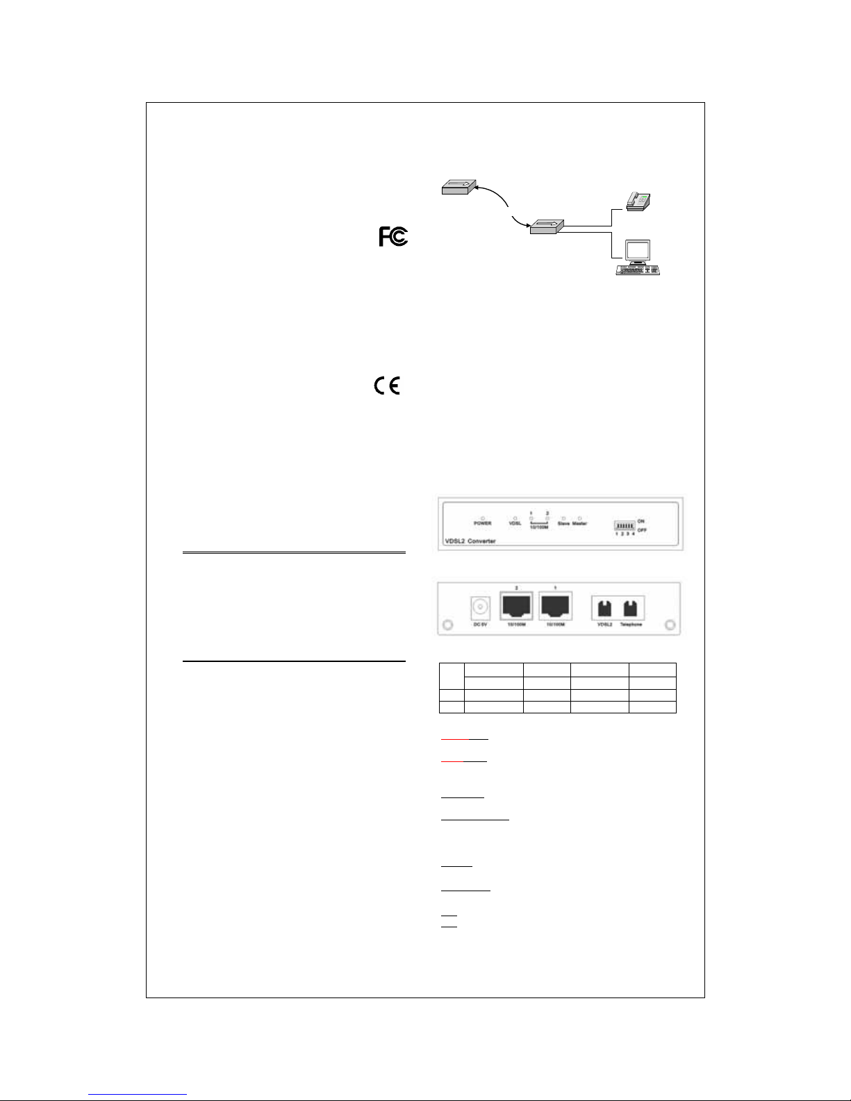
The drawing listed b e low is t y p ica l a pplication for the
Ethernet over VDSL2 converter.
Telephone
Slave
Master
Phone line
Key Features
E802.3 10BASE-T standard.
rd.
y
he Rear Panel
Dip Switch Settings
Pin3 Pin4
y Complies with IEE
y Complies with IEEE802.3u 100BASE- TX standa
y Compliance with VDSL2 ITU-T G.993.2
y Supports 1 * RJ-11 port for Ethernet over VDSL2.
y Provides 1 * RJ-11 port for telephone connection.
y Provides 2 * RJ-45 ports for 10/100Mbps Ethernet.
y Provides 1 * Dip Switch f or mode select ion
line y V oice and Data work on the same telephone
y EoVDSL2 port supports maximum
stream bandwidth 100Mbps/50Mbps (down
/upstream) over 1000ft (300m)
Long Reach VDSL2 performance around 7Mbps
downstream over 5000ft (1500m)
y Mini size design (120 x 75 x 25mm)
y Provides r ich diagnos tic LED indicat ors
y External Power Adapter
The Front Panel
T
Pin1 Pin2
Side Mode R t ate limi SNR
ON Sla E) ve (CP Fast No limit 6dB
OFF Master (CO) Interleave 5 0/20 Mbps 9dB
Pin1: Master, slave switch
Master(CO): EoVDSL2 converter acts as Master /
Central Office (CO) side.
Slave(CPE): EoVDSL2 converter acts as Slave /
Customer Premise Equipment (CPE) side.
Pin2: Impulse noise protection
Fast mode: Direct data transmission with latency less
than 1 ms.
Interleave mode: Provides communication protection
for up to 250ms impulse no ise with latency less tha n 6
ms.
Pin3: Rate limit control
No limit: Provides up to 100Mbps/50Mbps line rate in
s
short line.
50/20 Mbp : Line r ate limited to 50/20Mbps.
Pin4: General protection
6dB: Original channel nois e protection with 6 dB SNR.
9dB: Better channel noise protection with SNR up to 9
dB.
Note: SNR (Signal Noise Rate) = Signal / Noise. Switch on this
pin depends on your network demand.
Page 2
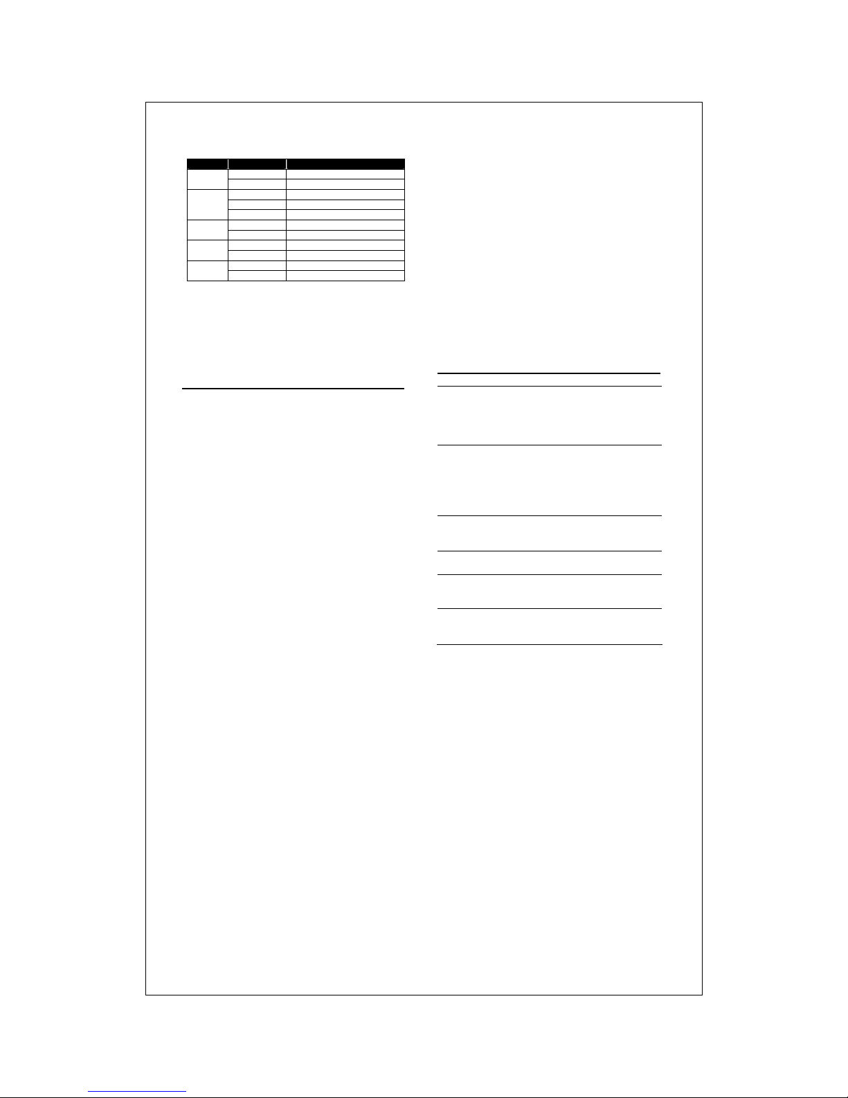
LEDs Definition
LED Status Operation
Green The device is powered on.
Power
Off The device is powered off .
Green The port is connected.
*Blinking Green Data transceiving.
VDSL
Off No valid link on this port
Green The port is connected.
10/100M
*Blinking Green Data transceiving.
Green The device acts as Mast er mode.
Master
Off The master mode is off .
Green The device acts as Slave mode.
Slave
Off The slave mode is off.
* Once the converter connects to a power source, the
LEDs of 10/100M will blink once, and the converter
begins looking for other converter automatically.
During searching, the VD SL LEDs keeps b linking; it
will stop blinking after success detection.
Installing and Usin g
VDSL2 Converter
Installing the Ethernet over VDSL2
Converter
The converter does not require any software
configuration. Users can immediately use any feature
of this product simply b y attaching the cables and plu g
power on. There is some key limitation on the
Ethernet over VDSL2 networking, please check the
following items:
y The device is used for point-to-point connection only
and allows data and voice work on the same
telephone lines.
y The two RJ-11 connectors, one for voice device
connection (like telephone) and the other one for
network line connection
This device is an ideal client access unit for the
applications of apartment, hotel, campus and
hospitality. Integration with the Internet access
Concentrator, the total infrastructure could be a
perfect solution for multi-media local Internet. This
structure could support many multi-media
applications, like VOD (Video on Demand), Distant
education, Internet caching server, … and so on.
Therefore, most of the traffic will be limited on the local
phone line network instead of flooding to the Internet.
Another application for the converter is used for LAN
to LAN extension through the normal telephone line.
Connect to Internet Access Concentrator
In order to build up a local Internet in apartment, hotel,
campus and hospitality environment, the Internet
Access Concentrators need to be placed in the wiring
center (MDF room) and connect to the telephone line
system. On the other hand, you need to install a
converter on the individual client side and connect to
the Concentrator through the telephone lines.
When deciding where to put the converter then you
must ensure:
y It is accessible and cables can be connected easily.
Cabling is away from sources of electrical noise such
as radios, transmitters and power lines and
fluorescent lighting fixtures.
y W ater or moisture cannot enter the unit.
y Airflow around the unit and through the vents in the
side of the case is not restricted (company
recommend that you provide a minimum of 25mm
clearance).
T o prolong the operational life of your units:
y Do not place objects on top of any unit or stack.
y Do not obstruct any vents at the sides of the case.
Installing Network Cables
After placing the converter on the desktop, then we
need to know how to connect the device to network.
Station Connections with Telephone Wires
Connect the network adapters in stations to the
converter’s RJ-45 port through category 3, 4 or 5
UTP/STP cables. There are two RJ-11 phone jacks;
one for telephone set connection and the other one is
used for phone line network connection. If you have
telephone wall jacks at home then all you need to do is
connecting the RJ-11 network port to the wall jack
through telephone wires.
Product Specifications
Standard
IEEE802.3 standard
IEEE802.3u standard
Ethernet over VDSL2
VDSL2 ITU-T G.993.2
Interface
2 * RJ-45 10/100Mbps Ethernet ports
1 * RJ-11 connector for EoVDSL2
1 * RJ-11 connector for telephone
connection
1 * DIP switch for selective
transmission modes
LED
indications
Power*1, VDSL*1, LAN*2,
Master mode*1, Slave mode*1
Emission FCC Class A, CE, VCCI Class A
Operating
Temperature
Operating -- 00- 400C (320- 1040F)
Storage -- -10
0
- 700C
Operating
Humidity
Operating -- 10% ~ 90%
(non-condensing)
Storage – 5%~95%
61NB-VE6840+204
 Loading...