

Page 1

User’s Manual of VCG-1500WG-LTE
1
VCG-1500WG-LTE
Vehicle 4G LTE Cellular Wireless
Gateway with 5-Port 10/100TX
Page 2

User’s Manual of VCG-1500WG-LTE
2
Trademarks
Copyright © PLANET Technology Corp. 2018.
Contents are subject to revision without prior notice.
PLANET is a registered trademark of PLANET Technology Corp. All other trademarks belong to their respective owners.
Disclaimer
PLANET Technology does not warrant that the hardware will work properly in all environments and applications, and makes no
warranty and representation, either implied or expressed, with respect to the quality, performance, merchantability, or fitness for
a particular purpose. PLANET has made every effort to ensure that this User's Manual is accurate; PLANET disclaims liability
for any inaccuracies or omissions that may have occurred.
Information in this User's Manual is subject to change without notice and does not represent a commitment on the part of
PLANET. PLANET assumes no responsibility for any inaccuracies that may be contained in this User's Manual. PLANET makes
no commitment to update or keep current the information in this User's Manual, and reserves the right to make improvements to
this User's Manual and/or to the products described in this User's Manual, at any time without notice.
If you find information in this manual that is incorrect, misleading, or incomplete, we would appreciate your comments and
suggestions.
FCC Warning
This equipment has been tested and found to comply with the limits for a Class A digital device, pursuant to Part 15 of the FCC
Rules. These limits are designed to provide reasonable protection against harmful interference when the equipment is operated
in a commercial environment. This equipment generates, uses, and can radiate radio frequency energy and, if not installed and
used in accordance with the Instruction manual, may cause harmful interference to radio communications. Operation of this
equipment in a residential area is likely to cause harmful interference in which case the user will be required to correct the
interference at his own expense.
CE Mark Warning
This is a Class A product. In a domestic environment, this product may cause radio interference, in which case the user may be
required to take adequate measures.
Energy Saving Note of the Device
This power required device does not support Standby mode operation. For energy saving, please remove the power cable to
disconnect the device from the power circuit. In view of saving the energy and reducing the unnecessary power consumption, it
is strongly suggested to remove the power connection for the device if this device is not intended to be active.
WEEE Warning
To avoid the potential effects on the environment and human health as a result of the presence of hazardous
substances in electrical and electronic equipment, end users of electrical and electronic equipment should
understand the meaning of the crossed-out wheeled bin symbol. Do not dispose of WEEE as unsorted
municipal waste and have to collect such WEEE separately.
Revision
PLANET VCG-1500WG-LTE User's Manual
Model: VCG-1500WG-LTE
Revision: 1.0 (July, 2018)
Part No: EM-VCG-1500WG-LTE _v1.0
Page 3

User’s Manual of VCG-1500WG-LTE
3
TABLE OF CONTENTS
1. INTRODUCTION .................................................................................................................... 6
1.1 Packet Contents ........................................................................................................................................... 6
1.2 Product Description ..................................................................................................................................... 7
1.3 How to Use This Manual .............................................................................................................................. 9
1.4 Product Features ........................................................................................................................................ 10
1.5 Product Specifications .............................................................................................................................. 12
2. INSTALLATION ................................................................................................................... 14
2.1 Hardware Description ................................................................................................................................ 14
2.1.1 Vehicle Gateway Front and Rear Panels ............................................................................................................. 14
2.1.2 LED Indications ................................................................................................................................................... 15
2.1.3 Power Inputs ........................................................................................................................................................ 16
2.1.4 SIM Card Installation ........................................................................................................................................... 17
2.1.5 Antenna Installation ............................................................................................................................................. 18
2.1.6 RJ45-DB9F Instruction ........................................................................................................................................ 18
2.2 Mounting Installation ................................................................................................................................. 19
3. QUICK CONFIGURATION ................................................................................................... 20
3.1 Inserting SIM Card into Gateway’s SIM Card Slot ................................................................................... 20
3.2 Connecting Antennas ................................................................................................................................ 20
3.3 Connecting LAN 2 Port of Gateway with PC ........................................................................................... 20
3.4 Logging in to the Vehicle Gateway ........................................................................................................... 20
3.5 LED and System Status ............................................................................................................................. 20
4. BASIC CONFIGURATION ................................................................................................... 22
4.1 WAN Configuration .................................................................................................................................... 22
4.2 PPPoE Configuration ................................................................................................................................. 24
4.3 LAN Configuration ..................................................................................................................................... 24
4.4 Wi-Fi Configuration .................................................................................................................................... 26
4.5 DHCPD Configuration ................................................................................................................................ 28
Page 4

User’s Manual of VCG-1500WG-LTE
4
4.6 Dynamic Domain Name Server (DDNS) Configuration ........................................................................... 28
4.6.1 PLANET DDNS ............................................................................................................................................ 29
4.7 Keep Alive ................................................................................................................................................... 32
5. ADVANCED CONFIGURATION .......................................................................................... 34
5.1 IP Table Filter .............................................................................................................................................. 34
5.1.1 IP Filter Rule Configuration .................................................................................................................................. 35
5.1.2 MAC Filter Configuration ..................................................................................................................................... 37
5.2 NAT/DMZ Configuration ............................................................................................................................. 39
5.3 Router Configuration ................................................................................................................................. 40
5.4 VPN Configuration ..................................................................................................................................... 42
5.4.1 GRE ..................................................................................................................................................................... 42
5.4.2 PPTP ................................................................................................................................................................... 43
5.4.3 IPSEC .................................................................................................................................................................. 45
5.4.4 L2TP .................................................................................................................................................................... 46
6. System Management .......................................................................................................... 48
6.1 Time Management ...................................................................................................................................... 48
6.2 User Management ...................................................................................................................................... 48
6.3 System Status ............................................................................................................................................. 49
6.4 Software Upgrade ....................................................................................................................................... 50
6.5 System Debug ............................................................................................................................................ 50
7. Internet Access Management ............................................................................................ 52
7.1 Captive Portal ............................................................................................................................................. 52
7.2 WiFidog Configure ..................................................................................................................................... 53
7.3 Application Filtering ................................................................................................................................... 54
7.4 Follower ....................................................................................................................................................... 55
7.5 Battery Power Feature Config ................................................................................................................... 55
7.6 GPS Function .............................................................................................................................................. 56
8. Other Configurations ......................................................................................................... 59
Page 5

User’s Manual of VCG-1500WG-LTE
5
8.1 Activation Mode .......................................................................................................................................... 59
8.2 Bandwidth Management ............................................................................................................................ 62
8.3 Connecting Device (MAC Address Binding) ........................................................................................... 63
8.4 Other Configurations ................................................................................................................................. 64
8.5 Timing Restart ............................................................................................................................................ 65
8.6 DTU Configuration ..................................................................................................................................... 66
Appendix: FAQs ..................................................................................................................... 68
Page 6

User’s Manual of VCG-1500WG-LTE
6
Model Name
4G LTE
Wi-Fi
FDD
TDD
VCG-1500WG-LTE-EU
B1/B3/B5/B7/B8/B20
B38/B40/B41
ETSI
VCG-1500WG-LTE-US
B1-5/7/8/13/17-20
-
FCC
1. INTRODUCTION
Thank you for purchasing PLANET Vehicle 4G LTE Cellular Gateway. Please refer to the table list below for the models used in
Europe and the U.S.:
“Vehicle Gateway” is used as an alternative name in this user’s manual.
1.1 Packet Contents
Open the box of the Vehicle Gateway and carefully unpack it. The box should contain the following items:
VCG-1500WG-LTE x 1
Quick Installation Guide x 1
4G LTE Antenna x 1
2.4G Wi-Fi Antenna x 2
GPS Antenna x 1
Ethernet Cable x 1
Console Cable x 1
Mounting Kit x 1
Power Kit x 1
Antenna Dust Cap x 4
Copper Dust Cap x 6
If any item is found missing or damaged, please contact your local reseller for replacement.
Page 7

User’s Manual of VCG-1500WG-LTE
7
1.2 Product Description
Internet of Vehicles via 4G LTE Vehicle Gateway
PLANET VCG-1500WG-LTE is a reliable, secure and high-bandwidth communications Vehicle Gateway for demanding mobile
applications and IoV deployments. It features 4G LTE (Long Term Evolution), wireless AP, five Ethernet ports (4 LAN and 1
WAN), GPS, VPN technology and bandwidth management bundled in a mountable metal case to establish a public network
connection and allow passengers to access Internet.
High-performance 4G LTE
The VCG-1500WG-LTE is able to reach a download (DL) speed of up to 100Mbps and an upload (UL) speed of 50Mbps. The
Vehicle Gateway also supports multi-band connectivity including LTE FDD, TDD, HSDPA, WCDMA and GSM for a wide range
of applications.
Wireless Access Point
With an integrated 802.11n Wireless Access Point, the gateway supports data rate up to 300Mbps and is also compatible with
2.4GHz 802.11b/g/n equipment. The Wireless Protected Access (WPA-PSK/WPA2-PSK) and Wireless Encryption Protocol
(WEP) features enhance the level of transmission security and access control over Wireless LAN.
GPS Included
The VCG-1500WG-LTE is equipped with one convenient feature and that is GPS (global positioning system). It is a positioning
system based on a network of satellites that continuously transmit necessary data. More signals transmitted from more satellites
can triangulate its location on the ground, meaning any location can be easily tracked anytime.
Cost-effective VPN Solution
The VCG-1500WG-LTE provides a complete data security and privacy feature for access and exchange of sensitive data. The
full VPN capability of the VCG-1500WG-LTE including built-in PPTP, LT2P, and IPSec VPN client functions with
DES/3DES/AES encryption and MD5/SHA-1 authentication makes the shared connection more secure and flexible. The IPSec
VPN also makes the private tunnel over Internet more secure for enterprises doing business transactions.
Dual TF Cards for Wi-Fi Advertising Contents
The VCG-1500WG-LTE provides dual TF cards and the capacity of each card is up to 128GB. The TF cards can store
thousands of advertising data and movie files. The administrator is able to upload these files to TF cards via FTP locally.
Besides, through the CMS (central management system), administrator is able to upload and maintain these files remotely.
The device will display advertising contents when users access to the Wi-Fi after authentication.
Superior Management Functions
For networking management features, the VCG-1500WG-LTE provides such functions as DMZ, QoS, Wifidog and SNMP, as
well as full secure functions including Network Address Translation (NAT) and IP/URL/MAC filtering. The VCG-1500WG-LTE
has 4G and WAN connection failover characteristics, which can automatically switch over to the redundant, stable WAN
connection to keep users always online without missing any fascinating moments.
Page 8

User’s Manual of VCG-1500WG-LTE
8
User-friendly and Secure Management
For efficient management, the VCG-1500WG-LTE is equipped with console, web and Wifidog management interfaces. With the
built-in web-based management interface, the VCG-1500WG-LTE offers an easy-to-use, platform independent management
and configuration facility. The VCG-1500WG-LTE supports Wifidog and it can be managed via the CMS for remote
management and Wi-Fi advertising.
Page 9

User’s Manual of VCG-1500WG-LTE
9
1.3 How to Use This Manual
This User Manual is structured as follows:
Section 2, INSTALLATION
The section explains the functions of the Vehicle Gateway and how to physically install the Vehicle Gateway.
Section 3, QUICK CONFIGURATION
The section contains the procedure of installing hardware and accessing the Web UI.
Section 4, BASIC CONFIGURATION
The section explains how to manage the Vehicle Gateway by Web interface.
Section 5, ADVANCED CONFIGURATION
The chapter explains how to set up the advanced function of the Vehicle Gateway.
Section 6, SYSTEM MANAGEMENT
The chapter explains how to troubleshoot the Vehicle Gateway.
Section 7, INTERNET ACCESS MANAGEMENT
The chapter explains how to set up remote management and advertising.
Section 8, OTHER CONFIGURATIONS
The chapter explains related functions of the Vehicle Gateway.
Appendix A
The section contains FAQ information of the Vehicle Gateway.
Page 10

10
1.4 Product Features
Physical Port
■ 4 10/100BASE-TX RJ45 LAN ports, auto-negotiation, auto MDI/MDI-X
■ 1 10/100BASE-TX RJ45 WAN port, auto-negotiation, auto MDI/MDI-X
■ 1 4G LTE 2.3 dBi antenna
■ 2 2.4G Wi-Fi 2dBi antennas
■ 1 GPS antenna
■ 1 SIM card slot
■ 1 console port
■ 2 TF card slots to save files for Wi-Fi advertising
Cellular Interfaces
■ Supports multi-band connectivity with FDD LTE/ TDD LTE/ WCDMA/ GSM/ LTE Cat4
■ Built-in SIM and broadband backup for network redundancy
■ One detachable antenna for 4G LTE connectiion
■ LED indicators for connection status (3G/4G)
User’s Manual of VCG-1500WG-LTE
Wi-Fi Interfaces
■ Complies with IEEE802.11b/g/n 2.4GHz
■ Two detachable antennas for wireless connection
■ 64/128-bit WEP, WPA/WPA2 and WPA-PSK/WPA2-PSK (TKIP/AES encryption)
■ LED indicators for status
Case and Installation
■ IP30 aluminum case
■ Mounting brackets for vehicles
■ Power requirement: 6~32V DC
■ Supports 15KV DC Ethernet ESD protection
■ -25 to 65 degrees C operating temperature
Advanced Features
■ Supports demilitarized zone (DMZ)
■ Supports VPN client, including GRE, PPTP, IPSec, L2TP
■ Supports NAT port mapping function, such as SNAT and DNAT
■ Supports Static Routing to display current routing information of the gateway
■ Supports QoS for bandwidth management
■ Supports Dynamic DNS and PLANETDDNS
■ Supports WAN connection types: DHCP client, static IP and PPPoE client
■ Secures network connection
IP filter
URL filter
MAC filter
Page 11

11
Management
■ Gateway management interfaces
- Console/Telnet Command Line interface
- Web management
■ Gateway Maintenance
- Firmware upload via HTTP, and TFTP
- Restore or Reset button for reset to factory default
- Dual images
■ SNTP (Simple Network Time Protocol)
■ System log
■ System tool, such as ping and trace
■ Configuration backup and restore
■ Supports CMS and Wifidog for remote management, and Wi-Fi advertising
User’s Manual of VCG-1500WG-LTE
Page 12
12
Product
VCG-1500WG-LTE
Hardware Specifications
Copper Ports
4 LAN 10/100BASE-TX RJ45 auto-MDI/MDI-X ports
1 WAN 10/100BASE-TX RJ45 auto-MDI/MDI-X port
Console
1 x RS232-to-RJ45 serial port (115200, 8, N, 1)
SIM Interface
1 SIM card slot with mini SIM card tray
Cellular Antenna
1 2dBi external antenna with SMA connector for LTE
Wi-Fi Antenna
2 2dBi external antennas with SMA connectors for 2.4GHz
GPS Antenna
1 28dB gain external antennas with SMA connectors for GPS -3m
USB Interface
1 USB 2.0 for external storage
TF Card Interface
2 TF card for storing thousands of advertising data (max. capacity up to 128G for each)
Connector
Standard 4-pin vehicle power jack for power input
Reset Button
> 5 sec: Factory default
ESD Protection
15KV DC
Enclosure
IP30 metal case
Installation
Mounting brackets for vehicles
LED
System:
PWR (Red)
Ethernet Interfaces (Port1-4 and WAN Port):
LNK (Green)
ACT (Orange)
LTE SIM and Signal :
3G/4G (Blue)
Wi-Fi (Blue)
Internet (Blue)
Dimensions (W x D x H)
168 x 104 x 25 mm (not including antenna and connector)
Weight
537g (not including antenna)
Power Requirements –
DC
6~32V DC, 1.5A
Power Consumption
3 watts/10.23 BTU
Multi Band Supports
EU Model
FDD LTE B1/B3/B5/B7/B8/B20 (2100/1800/850/2600/900/800)
TDD LTE B38/B40/B41 (2600/2300/2500)
WCDMA B1/B5/B8 (2100/850/900)
GSM/EDGE B3/B8 (1800/900)
US Model
FDD LTE B2/B4/B12 (1900/AWS1700/700)
WCDMA B2/B4/B5 (1900/AWS1700/850)
LTE Data Rate
20MHz bandwidth: 100Mbps (DL), 50Mbps (UL)
Wireless Specifications
Standard
IEEE 802.11 b/g/n 2.4GHz
Wireless Mode
Access Point
Operating Channels
FCC: 1~11, ETSI: 1~13
Encryption Security
64-/128-bit WEP, WPA, WPA-PSK, WPA2, WPA2-PSK
1.5 Product Specifications
User’s Manual of VCG-1500WG-LTE
Page 13

User’s Manual of VCG-1500WG-LTE
13
Data Rate
Up to 300Mbps
Transmission Distance
Up to 150 meters
*The estimated transmission distance is based on the theory.
The actual distance will vary in different environments
Advanced Functions
VPN
GRE, PPTP, IPSec, L2TP
QoS
Bandwidth management
WAN Connection Type
PPPoE, Static, DHCP client
Wifidog
Wifi authentication and advertising
Secure Network
IP filter
URL filter
MAC filter
Other
Supports demilitarized zone (DMZ)
Supports NAT port mapping function, UPnP
Supports Dynamic DNS
Management
Basic Management
Interfaces
Console, Telnet, Web browser
Standards Conformance
Regulatory Compliance
CE, FCC
Standards and Protocols
Compliance
IEEE 802.3 10BASE-T
IEEE 802.3u 100BASE-TX
IEEE 802.3x flow control and back pressure
RFC 768 UDP
RFC 791 IP
RFC 792 ICMP
RFC 5321 SMTP
RFC 2068 HTTP
RFC 1939 POP3
RFC 854 TELNET
RFC 959 FTP
Environment
Operating
Temperature: -25 ~ 65 degrees C
Relative Humidity: 95% (non-condensing)
Storage
Temperature: -40 ~ 85 degrees C
Relative Humidity: 95% (non-condensing)
Page 14
User’s Manual of VCG-1500WG-LTE
14
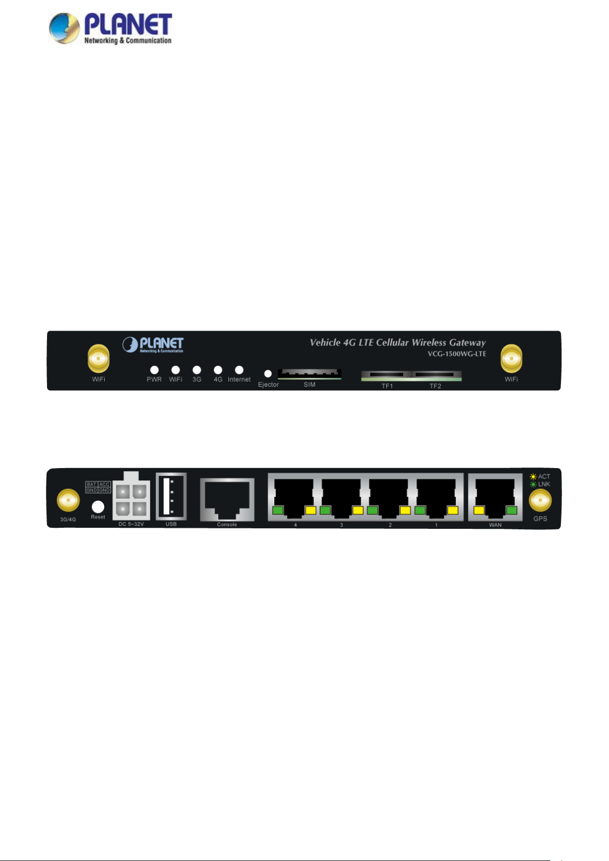
Figure 2-2 Rear Panel
Figure 2-1 Front Panel
2. INSTALLATION
This section describes the hardware features and installation of the Vehicle Gateway. For easier management and control of the
Vehicle Gateway, familiarize yourself with its display indicators and ports. Front panel illustrations in this chapter display the unit
LED indicators. Before connecting any network device to the Vehicle Gateway, please read this chapter completely.
2.1 Hardware Description
2.1.1 Vehicle Gateway Front and Rear Panels
The front panel provides the monitoring of the Vehicle Gateway’s simple interfaces. Figure 2-1 shows the front panel of the
Vehicle Gateway.
The rear panel provides the most of the connectors in the gateway. Figure 2-2 shows the rear panel of the Vehicle Gateway.
Page 15
User’s Manual of VCG-1500WG-LTE
15
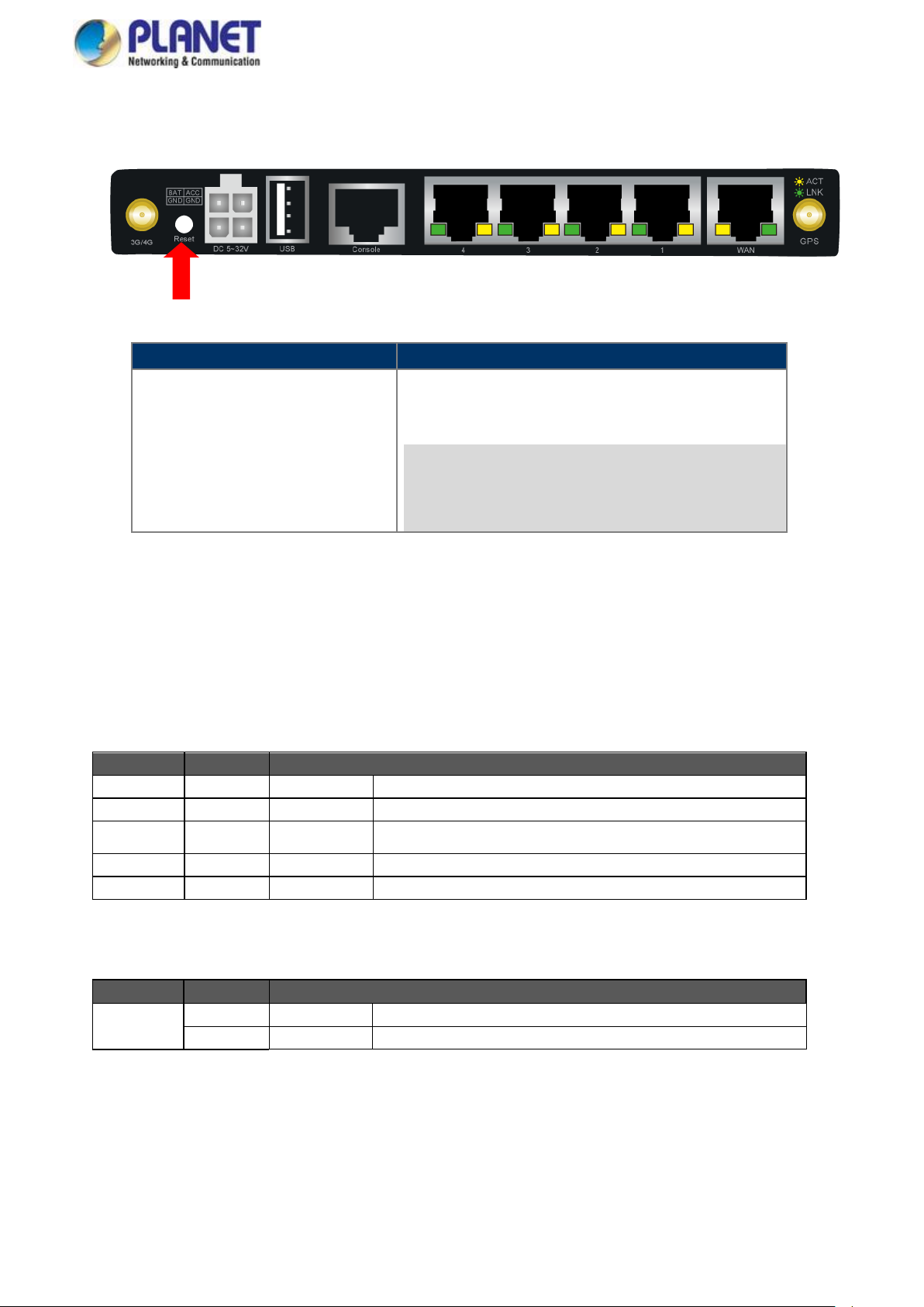
Reset Button
Function
> 5 sec: Factory Default
Reset the Vehicle Gateway to Factory Default configuration.
Vehicle Gateway will then reboot and load the default settings
shown below:
Default username: admin
Default password: admin
Default IP address: 192.168.1.1
Subnet mask: 255.255.255.0
LED
Color
Function
PWR
Red
Lights
Indicates the system is working properly.
Wi-Fi
Blue
Lights
Indicates the Wi-Fi is working. The Wi-Fi is enabled by default.
3G
Blue
Lights
Indicates the SIM card is detected via 3G
4G
Blue
Lights
Indicates the SIM card is detected via 4G.
Internet
Blue
Lights
Indicates the system is connecting to the Internet.
LED
Color
Function
Ethernet
Green
Blinking
LNK, indicates that the link is successfully established
Orange
Blinking
ACT, indicates that the port is operating at 100Mbps
Reset Button
On the rear of the VCG-1500WG-LTE, the reset button is designed to reset the Vehicle Gateway to factory default.
Figure 2-3 Reset Button of VCG-1500WG-LTE
2.1.2 LED Indications
The front and real panels’ LEDs indicate instant status related to system power, Wi-Fi, 4G and Internet. It helps monitor and
troubleshoot when needed.
System
10/100BASE-TX Port Interfaces (LAN Port-1 to Port-4, WAN)
Page 16
User’s Manual of VCG-1500WG-LTE
16
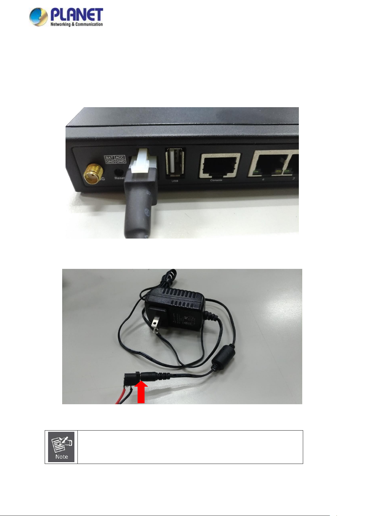
Except for the power adapter, the power cable also reserves two bare wires with positive
and negative poles so that the user can connect to the battery of the car.
2.1.3 Power Inputs
The 4-pin power connector on the rear panel of Vehicle Gateway is used for one DC power input. The power input range is from
6 to 32V DC. In the power kit, VCG-1500WG-LTE provides one power adapter and one power cable with 4-pin female power
jack. Please follow the steps below to insert the power wire.
1. Plug the 4-pin female power jack of the power cable into the power connector.
Figure 2-4: Plugging in the Power Input
2. Connecting power adapter with power cable.
Figure 2-5: Connecting Power Cable with Power Adapter
Page 17
User’s Manual of VCG-1500WG-LTE
17
Please make sure the direction first. When pulling into the SIM tray without putting the correct
direction, the tray will be stuck inside.
Please turn off Vehicle Gateway before removing the SIM card.
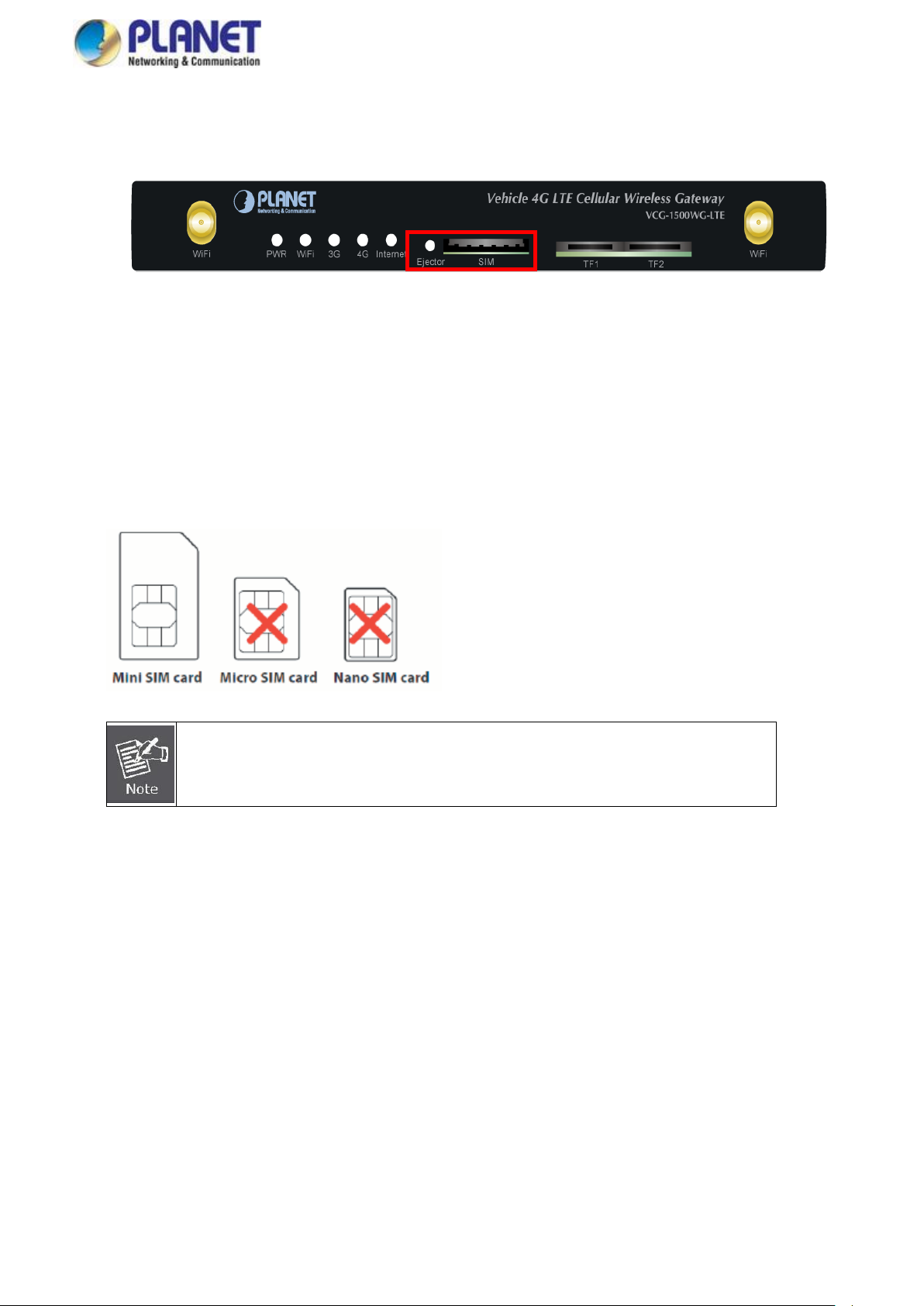
2.1.4 SIM Card Installation
1. SIM Card Drawer and Eject Button
Figure 2-6: SIM Card Slot and Ejector
2. Inserting and Removing SIM Card
(1) Before inserting or removing the SIM card, ensure that the power has been turned off and the power connector has
been removed from Vehicle Gateway.
(2) Press the ejector button with a paper clip or suitable tool to eject the SIM card from the drawer.
(3) Insert the SIM card with the contacts facing down and align it properly into the drawer. Make sure your direction of
SIM card and put it into the tray.
(4) Slide the drawer back and lock it in place.
A mini card with LTE and WCDMA subscription.
Page 18

User’s Manual of VCG-1500WG-LTE
18
RJ45
DB9F 1 8 2 6
3
2
4 1 5 5 6 3 7 4 8
7
PIN
RS232 Signal
Name
Description
Direction related to
DTU
1
DCD
carrier wave
signal check
Output
2
RXD
receive data
Output
3
TXD
send data
Input
4
DTR
data
terminal ready
Input
5
GND
power reference
ground
6
DSR
data
device ready
Output
7
RTS
request to send
Input
8
CTS
data device gets
ready to receive
data
Output
2.1.5 Antenna Installation
After SIM card installation, please connect 4G antenna, GPS antenna and Wi-Fi antennas to connectors and ensure these
antennas are fixed properly. Without installing antennas, it will affect the performance or can not receive the signal.
2.1.6 RJ45-DB9F Instruction
This Gateway supports RS232 asynchronous communication serial interface and adopts RJ45. Serial interface is mainly used
to configure control or configured to be DTU function.
Com/line: RS232 asynchronous communication serial interface
Shown below are the signal definitions of the RJ45-DB9F serial communication interfaces:
The signal definitions of the DB9F serial communication interface shown below::
Page 19
User’s Manual of VCG-1500WG-LTE
19
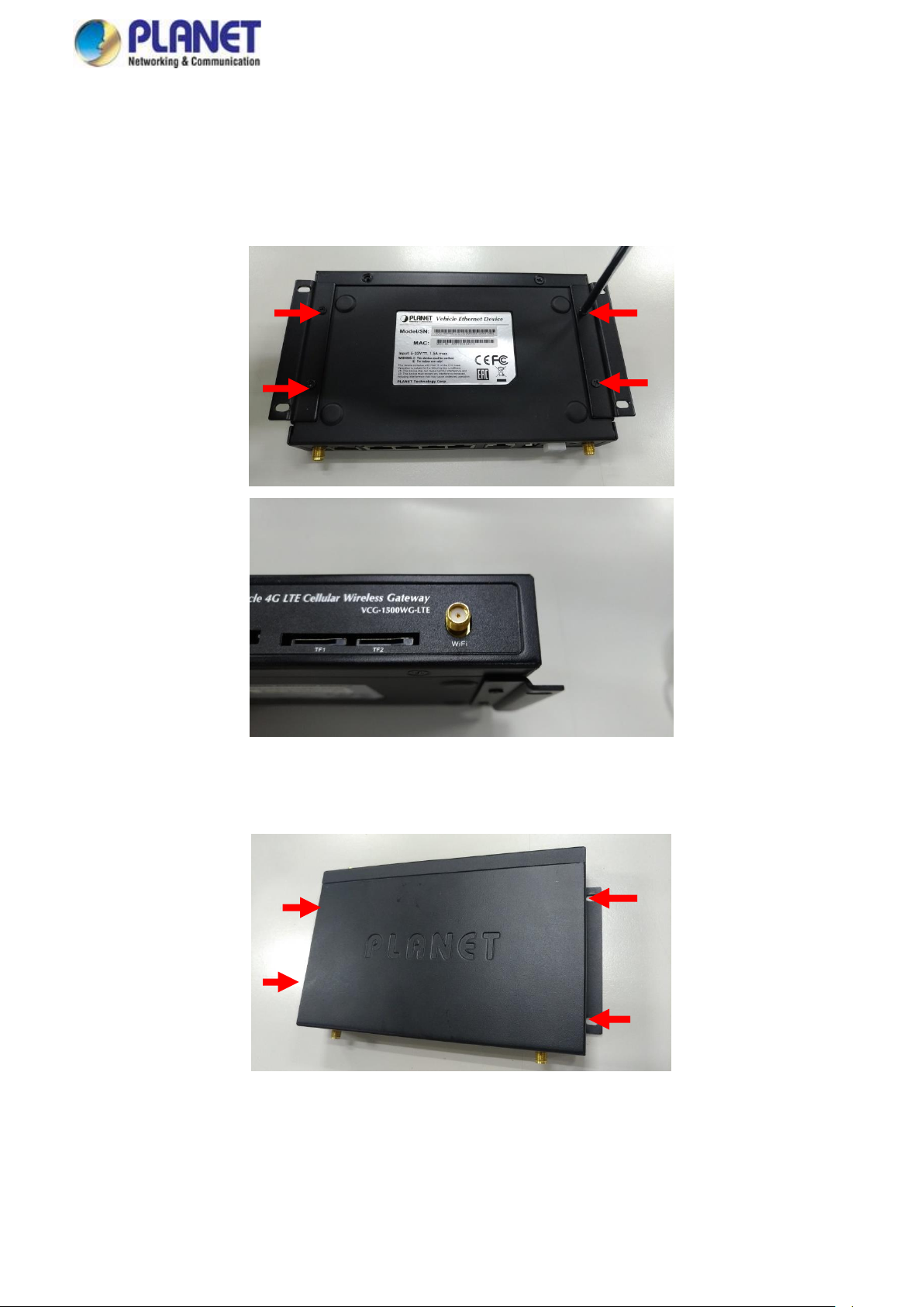
2.2 Mounting Installation
This section describes how to install your Vehicle Gateway and make connections to the Vehicle Gateway. To install your
Vehicle Gateway on a desktop or shelf, simply complete the following steps.
Step 1: Screw the brackets on the Vehicle Gateway.
Step 2: Place the Vehicle Gateway in the car where you need to install it, and then lock the screws.
Page 20
User’s Manual of VCG-1500WG-LTE
20
3. QUICK CONFIGURATION
This chapter explains the procedure that you can install and configure the Gateway in a short time. Besides, it also contains
information about port connection options.
3.1 Inserting SIM Card into Gateway’s SIM Card Slot
3.2 Connecting Antennas
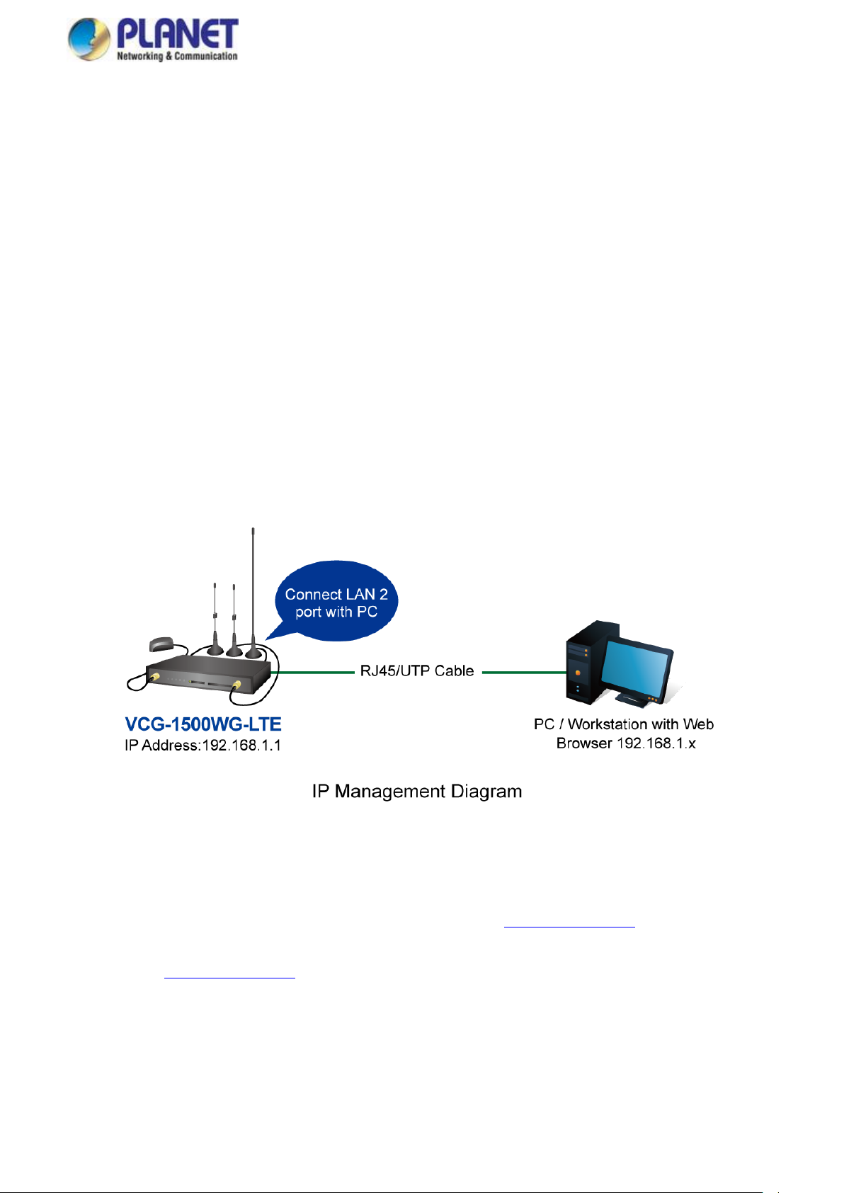
3.3 Connecting LAN 2 Port of Gateway with PC
Please connect the gateway and PC to the same switch. The default IP address of LAN 2 port is 192.168.1.1 and the port
number is 9999. In the PC, please make sure the manager PC must be set to the same IP subnet address.
For example, the default IP address of the gateway is 192.168.1.1, then the manager PC should be set to 192.168.1.x (where x
is a number between 2 and 254), and the default subnet mask is 255.255.255.0
Figure 3-3-1 Web Management
3.4 Logging in to the Vehicle Gateway
Use Internet Explorer 8.0 or above Web browser and enter default IP address http://192.168.1.1:9999 to access the Web
interface.
After entering the http://192.168.1.1:9999 the following dialog box will appear. Please enter the default user name and password
“admin”.
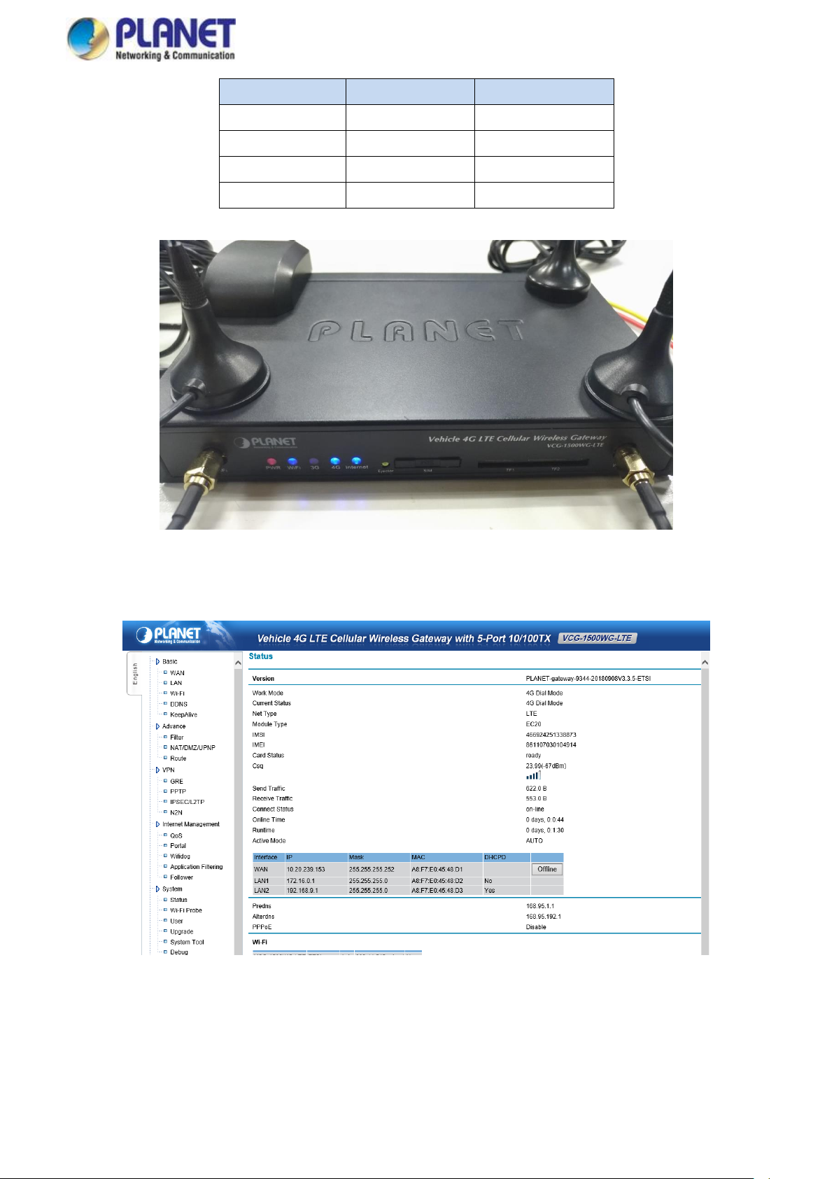
3.5 LED and System Status
When the gateway is working properly, the LED status should display as shown below:
Page 21
User’s Manual of VCG-1500WG-LTE
21
LED
Color
Status
PWR
Red
Solid Light
WiFi
Blue
Solid Light
3G/4G
Blue
Solid Light
Internet
Blue
Solid Light
Figure 3-5-1 LED Status
Figure 3-5-2 System Status
Page 22

User’s Manual of VCG-1500WG-LTE
22
Object
Description
Calling Center Number,
Access Point Name,
Username and Password
Usually the information is default setting (refer to Appendix 5). Usually it doesn’t need to
revise it. If APN/VPND is used, it needs to type these information supplied by ISP to the
exact place.
PIN Code
If mobile UIM/SIM card is used to set a PIN code, please input it here.
Extra Initialization
Commands
It is usually blank here. If customer has any especial command, customer can input here.
The Way to Obtain IP
To obtain IP automatically, specify the local IP and specify the remote client’s IP. Default
situation is to obtain IP automatically; it is the IP address assigned by ISP when wireless
dial-up is made. If “Specify IP address” is selected, please input it according to ISP
supplied information. Otherwise, it can’t be online by dial-up. If ISP requires specifying
one kind, and the other one is obtaining automatically, please input 0.0.0.0.
1. PIN code can’t be input casually to avoid locking the card.
2. Please don’t input extra initialization command casually to avoid dial-up which is unavailable.
3. Please don’t specify IP casually unless it is required to do so by ISP, otherwise, online is
4. BASIC CONFIGURATION
This section introduces the configuration and functions of the Web-based management.
4.1 WAN Configuration
Gateway dial-up configuration is the basic parameter of connecting wireless network.
Figure 4-1-1 Main Page
Page 23

User’s Manual of VCG-1500WG-LTE
23
unavailable.
Page 24

User’s Manual of VCG-1500WG-LTE
24
Object
Description
User Name
User name access to public network, supplied by ISP
PIN Code
Password access to public network, supplied by ISP
4.2 PPPoE Configuration
PPPOE is the short name of point-to-point protocol over Ethernet, and it can make Ethernet host connect with remote access
concentrator by a simple bridge equipment
Figure 4-2-1 PPPoE
4.3 LAN Configuration
Gateway Ethernet port configuration (local IP address and DHCP server)
Figure 4-3-1 LAN
Page 25

User’s Manual of VCG-1500WG-LTE
25
Object
Description
Local Interface 1 (LAN1)
Multiplex with WAN -- It can be used to connect with LAN if without using PPPOE
IP Address
The default setting of the IP address of the gateway LAN1 interface is 192.168.0.1
Subnet Mask
Set Subnet Mask corresponding local IP address
Local Interface 2 (LAN2)
Used to connect with Wi-Fi and 4-port LAN
IP Address
The default setting of the IP address of the gateway Wi-Fi and LAN1-4 interface is
192.168.1.1
Subnet Mask
Set Subnet Mask corresponding local IP address. Default setting of Subnet Mask is
255.255.255.0
Primary DNS/Second DNS
It is the domain name decoding server address, and default situation (blank) is
obtained from ISP when gateway dial-up is made. If customer has stable DNS server, it
can input customer stable DNS server address, but we suggest that it is better to
obtain from ISP when gateway dial-up is made.
Note:
1. Make sure all IPs connected to equipment are in the same Subnet Mask with gateway.
2. When multi units work in the same LAN, MAC address will restore to default setting after “load default setting”. It is easy to
make MAC address conflict with other equipment. So please revise MAC address.
3. If users input DNS server address, after dialing, please check whether DNS used by gateway can decode domain name.
4. Local interface 1 and Local interface 2 can’t be in the same subnet mask
Page 26

26
Object
Description
SSID
Sign the wireless network name. It supports a maximum of 32 characters which is default
for theVCG-1500WG-LTE. We suggest revise it to avoid conflict with our company’s
other products.
Region
Display the standard which this deivce works
Channel
Select this device working channel. It doesn’t need to revise wireless channel except
there are interferences with other access points nearby. Priority Channel are 1,6, and 11.
The default setting is Auto.
Mode
Select mode this device will work.
802.11B only: Only supports 802.11B.
802.11 G only: Only supports 802.11 G.
802.11G/N mixed: Suppors G or N.
Option
It provides None, WEP, WPA-PSK and WPA2-PSK options for Wi-Fi security.
WEP: It adopts WEP 64- or 128-bit data encryption.
WPA-PSK: It adopts WPA-PSK standard encryption; use pre-shared key protection
access.
WPA2-PSK: It adopts WPA2-PSK standard encryption; use pre-shared key protection
access. Encryption type is AES.
WEP Encryption
Authentication: Default is Auto; if default can’t work normally, customer can choose
Shared (Open system).
Encryption: 64 bits or 128 bits
Passphase: WEP key -- customer can input by hand or adopt program that creates
encryption key automatically. Customer on wireless network has to input
encryption key value correctly to make connection successfully.
4.4 Wi-Fi Configuration
User’s Manual of VCG-1500WG-LTE
Figure 4-4-1 Wi-Fi
The page includes the following fields:
Page 27

User’s Manual of VCG-1500WG-LTE
27
WPA-PSK Encryption
Encryption Mode: It supports TKIP, AES, and TKIP/AES.
Passphase: The length of the encryption key is 8 to 63 characters.
WPA2-PSK Encryption
Encryption Mode: It supports TKIP, AES, and TKIP/AES.
Passphase: The length of the encryption key is 8 to 63 characters.
Page 28

User’s Manual of VCG-1500WG-LTE
28
Object
Description
Start IP, End IP
They are start and end addresses when DHCP server assigns IP automatically. After
setting IP address, internal computer received from this gateway is between these two
addresses
4.5 DHCPD Configuration
DHCP is Dynamic Host Control Protocol. It can assign IP address to computers in the LAN automatically. For customers, it is not
easy to set TCP/IP protocol parameters to all LAN computers. There are IP address, subnet mask, gateway, DNS server and so
on. Problems can be solved easily by using DHCP. The system default is open. If customer doesn’t use DHCPD service, please
close this selection.
Figure 4-5-1 DHCP Server
Note:
1. DHCP start IP and end IP are a must, and they are in the same subnet with gateway, but can’t include gateway local IP ;
otherwise, DHCP server can’t work normally.
2. Lapped DHCP servers can’t be existed in the same LAN. If there are multi devices using DHCP server function in the same
LAN, it can cause IP address to unable to assign normally in the system. It needs to stop one DHCP server.
3. If PPPOE is used, don’t use “local interface 1” DHCPD.
4.6 Dynamic Domain Name Server (DDNS) Configuration
DDNS stands for dynamic DNS, or more specifically dynamic Domain Name System. It's a service that maps internet domain
names to IP addresses. It's a DDNS service that lets you access your home computer from anywhere in the world. The gateway
provides DYNDNS, PLANET DDNS and Easy DDNS options.
Page 29

User’s Manual of VCG-1500WG-LTE
29
Figure 4-6-1 DDNS
4.6.1 PLANET DDNS
In order to properly configure the DDNS service function, please register a free DDNS domain name and account from PLANET
DDNS first. Go to http://www.plnaetddns.com from the browser to do so.
Figure 4-6-1-1 PLANETDDNS Website
Fill in the necessary fields as illustrated below. The page will check whether or not another user has used the host name you
entered as soon as you click the “Submit” button. If you see the message below, it means the domain name is created
successfully.
Page 30

User’s Manual of VCG-1500WG-LTE
30
Figure 4-6-1-2 Domain Registration
Figure 4-6-1-3 PLANETDDNS Domain added
Go back to the gateway’s DDNS service configuration page under “Basic”. Fill in the domain name you picked during the
registration in the “Host Nme” field and the username/password you created in the “User ID” and “Password” filed and click
“Apply” to finish
Page 31

User’s Manual of VCG-1500WG-LTE
31
Figure 4-6-1-4 PLANETDDNS Configuration
Page 32

User’s Manual of VCG-1500WG-LTE
32
Object
Description
Rule 1: PING Mode
Wireless gateway checks destination IP address through PING (ICMP) packet
periodically. When the referenced destination IP address device doesn’t
respond to PING (ICMP), wireless gateway considers communication line is
disconnected already, and it will release the original link, then dial-up again
automatically, till communication link is smooth. So please make sure the
selected IP server address is stable and on; otherwise, gateway will be judged
to be off-line, and make gateway on-line and off-line frequently.
Note: The selected destination IP address server is allowed to have PING; if
not allowed, the destination IP address server doesn’t respond to PING, and
thus the gateway will be considered to be off-line, and make gateway online
4.7 Keep Alive
Keeping Online function is used to check wireless gateway online status, this function checks periodically and automatically
data channel between gateway and wireless network whether normal or not. If it is found to be off-line, software will re-dial
automatically and intelligently, so that the device can always be online to make sure data channel smooth.
Wireless gateway supplies 4 kinds of online checking modes; customer can select one or more kinds. By default, Rule2 and
Rule3 are used.
Customer inputs stable “destination IP address” and “destination address port ”and regards them as the reference of online
maintenance. Please kindly noted the input “destination IP address” and “destination address port” must be stable, because
wireless gate is referred to this server; if this server is not stable, it will cause wireless network off-line frequently. When multi
rules are used, only when all selected rules find communication line is obstructed, wireless gateway can judge whether device is
off-line or not and restart connection automatically
Figure 4-7-1 Rule and No Reboot
The page includes the following fields:
Page 33

User’s Manual of VCG-1500WG-LTE
33
and off-line frequently.
Rule 2: TCP Mode
Wireless gateway checks destination IP address and port through TCP syn
packet periodically. When the destination IP address device doesn’t respond,
wireless gateway considers communication line is disconnected already.
Wireless gateway will release the original link, then dial-up again
automatically, till communication link is smooth. So please make sure the
selected destination address IP server is stable and on; otherwise, gateway is
considered to be off-line, and make gateway on and off-line frequently.
Note: The selected destination IP address server is checking relevant port. If
the selected destination IP address server is not stable or off or without
checking relevant port, gateway is considered to be off-line, and make
gateway on and off-line frequently.
Rule 3: Data Mode
In a certain period of time, if the gateway did not receive any data package,
then it is believed that the communication link disconnected, and it will dial-up
again till communication link is smooth
Rule 4: LCP Mode
Gateway checks online through LCP. In a certain period of time, if gateway did
not receive package, it will restart.
Please kindly note that the selected destination IP address server supports
PAP/CHAP verification function in order to use LCP checking. If the selected
destination IP address server is not stable or off or without supporting
PAP/CHAP verification function, gateway will consider dropped, and then it will
be on-line and off-line frequently.
Note:
1. Make sure to select one kind of maintenance in online mode; otherwise,
gateway can’t restart after dropped.
2. The input destination address needs to be stable and supply corresponding
services.
3. Keeping Online default is for public network; it needs to re-configure in
special network to avoid dropping frequently.
No Reboot
While the gateway does not connect to Internet, the watchdog function will
think the connection is disconnected and will continue to restart. You can
enable “No Reboot” to disable the watchdog funciton.
Page 34

User’s Manual of VCG-1500WG-LTE
34
Object
Description
Filter Mode
Client IP filtering and MAC address filtering -- Client can select according to their actual
need.
Client IP Filtering
Filter data according to IP address based on appointed policy to admit or prevent
corresponding IP address data.
MAC Filtering
Filter data according to MAC address based on appointed policy to admit or prevent
corresponding MAC address data.
Running Rules
This device has two kinds of running rules.
Discard matching
following rule data
packets
Data packets complied to the following rules are not allowed to go through; other data
packets can go through.
Receiving matching
following rule data
packets
Only receives data packets complied to the following rule; others are discarded.
5. ADVANCED CONFIGURATION
5.1 IP Table Filter
It is mainly used to filter wireless network data transmitting and receiving to prevent illegal and invalid data from gateway. It
admits and refuses computers with LAN connected with gateway to get access to WAN, or admits and refuses WAN to get
access to LAN connected with gateway.
The page includes the following fields:
Figure 5-1-1 Filter
Page 35

35
Object
Description
Rule Name
It is limited to use characters 0-9, a-z, and A-Z. Repeating the name is not possible.
LAN IP
The gateway connected LAN IP address
LAN Ports
The valid value of the LAN IP host address is 0~65535; please input from small to large.
WAN IP
Data packet destination IP address.
WAN Ports
The valid vaue of the data packet destination ports is 0~65535; please input from small
to large.
Protocol
There are 3 types of the data packet protocols:
ALL: All types of data packets.
TCP: All TCP packets.
UDP: All UDP packets.
Direction
The data packet direction is used to decide which one is the original address. There are
3 types:
IN: From outside network to gateway.
OUT: Transmit from gateway LAN.
IN/OUT: Include IN and OUT
Interface
Data packet goes through interface, such as br0, PPP0 and so on.
5.1.1 IP Filter Rule Configuration
To realize IP address filtering rules by appointing, revising and deleting.
User’s Manual of VCG-1500WG-LTE
Example 1 of IP addresses filtering:
1. If select “start client IP address filtering”
2. Running rules selection: “discard packets matching following rules”; click “ Apply” to save running rule. Instructions:
If “discard packets matching following rules” is selected, default rule is: wireless gateway allows all data to go through, but
does not allow data packet to go through.
Figure 5-1-1-1 Discard Packets Matching Following Rules
3. Input parameters in IP rule.
This example parameter is:
Page 36

User’s Manual of VCG-1500WG-LTE
36
Name:enableipfilter01
LAN IP: 192.168.1.23
WAN IP: 121.204.201.13
Protocol: all
Direction: IN
Interface: PPP0
4. Explanation and Introduction
After this rule is built, gateway will start IP address filtering function. According to running rule “Discard packet matching
following rule”, gateway discards all protocol data packets (select “ALL”) from WAN “121.204.201.13” (select “IN”direction)
in PPP0 interface (select “PPP0”interface), but other IP address data packets don’t comply to this rule that can come and
go normally.
Figure 5-1-1-2 Add Filter
Example 2 of IP addresses filtering:
1. select “setup client IP filter”
2. Running rule: “receive packet matches following rules”; click “Apply” to save.
Instructions: If “receive packet matches following rules” is selected, default rule is: Gateway forbids all data packet to go
through except data packet of picture.
Figure 5-1-1-3 Received Packet Matches Following Rules
3. Input parameters in IP rule.
Page 37

User’s Manual of VCG-1500WG-LTE
37
Object
Description
Rule Name
It is limited to use characters 0-9, a-z and A-Z. Repeating the same name is not possible.
MAC
Block or permit device MAC address; input format is“00:12:23:34:45:56”
This example parameter:
Name: enableipfilter02
LAN IP: 192.168.1.23
WAN IP: 121.204.201.13
Protocol: all
Direction: IN/OUT
Interface: PPP0
Click “Submit” to save.
4、Explanation and Instruction
After this rule is built, gateway will start IP address filtering function. According to running rule “Receive packet matching
following rule”, gateway forbids all data packet to go through, but only allows protocol data packets (select “ALL”) from WAN
“121.204.201.13”(select “IN/OUT” direction) to go through PPPO interface (select PPP0 interface). Usually this rule shields
invalid IP address to go through gateway, can reduce data flow, or as bank application, can shield other IP addresses to
access to bank IP address to realize filtering function and reduce data flow.
Figure 5-1-1-4 Add Filter
5.1.2 MAC Filter Configuration
Page 38

User’s Manual of VCG-1500WG-LTE
38
Example 1:
1、If select “setup MAC address filtering”
2、Running rule select: “discard packet matching following fule ”
3、Input“00:00:23:34:45:56”in MAC.
So gateway will discard all data packets of the MAC address “00:00:23:34:45:56”, meanwhile it permits all data packets
whose MAC address is not“00:00:23:34:45:56” to go through.
Example 2:
1、If select “setup MAC address filtering”
2、Running rule select: “receive packet matching following fule”
3、Input“00:00:23:34:45:56”in MAC.
So gateway only receives data packet whose MAC address is “00:00:23:34:45:56”, and discard all other data packets
whose MAC address is not “00:00:23:34:45:56”.
Page 39

User’s Manual of VCG-1500WG-LTE
39
Object
Description
Rule Name
It is limited to use characters 0-9, a-z and A-Z. Repeating the same name is not possible.
WAN Start Port
WAN data packet TCP/UDP start port value.
LAN IP
The translated LAN IP address
LAN Start Port
LAN computer start port
Port Number
Several continuous ports from start port. For example, start port is 5001, and port
number is 5, so translate WAN 5001,5002,5003,5004,5005 into LAN computer
192.168.1.9 port 5001,5002,5003,5004,5005
Protocol
TCP/UDP, TCP, UDP
Object
Description
DMZ
Set form is to select “Start DMZ”directly, then input virtual server IP in the IP address bar.
5.2 NAT/DMZ Configuration
NAT (Network Address Translation) is a technology which translates LAN IP address into a legal network IP through different
ports.
Mode 1: NAT
According to the appointed rule, it can translate data from WAN into an appointed LAN IP address or port.
Mode 2: DMZ
Expose one LAN computer to Internet completely to realize bi-directional communication. It needs to set this computer to be
virtual server (DMZ host computer). When there is WAN user visiting this virtual server translated public address, device will
transmit data packet to this virtual server directly. If one PC of wireless gateway LAN wants to communicate with internet, this
can be finished quickly by starting DMZ.
Page 40

User’s Manual of VCG-1500WG-LTE
40
Click “Apply”to save.
Object
Description
Name
It is limited to use characters 0-9, a-z and A-Z. Repeating the same name is not possible.
Destination IP address
Router destination IP can be host IP address,and also can be IP segment.
Subnet Mask
The added subnet, if it is the host IP address , please input
255.255.255.255
Gateway IP address
The next IP of the added router, if gateway is not needed, can be“0.0.0.0”
Metric
Default is 0
Interface
System interface
5.3 Router Configuration
Setup system static router setting and display system router information. System default router is to send all data to public
internet. If user wants to visit an appointed network, please add router by hand.
Figure 5-3-1 Route
Note: If router can’t be added successfully (add rules successfully, but router information didn’t display), please confirm NSID
whether to comply to requirements or not.
Gateway router configuration example:
Page 41

User’s Manual of VCG-1500WG-LTE
41
Figure 5-3-2 Topology
Introduction: There are three 192.168.1.0/24,192.168.3.0/24,192.168.2.0/24 networks.
192.168.1.2 is the gateway Ethernet LAN1-4 IP address.
110.91.69.133 is the ISP assigned PPP0 IP address when gateway dial-up is made.
192.168.2.8 is the occurred PPP1 tunnel IP address when gateway connects with server to build VPN tunnel.
172.16.0.1 is the VPN server ETH0 IP.
121.204.199.230 is the VPN server public IP.
192.168.2.6 is the occurred tunnel0 IP address when VPN server and wireless gateway built the VPN tunnel.
If computer with IP 172.16.0.2 wants to visit computer with IP 192.168.3.2, it needs to add one routing on VPN server to
visit 192.168.3.0/24 network. As for this adding step, please read our routing configuration user manual or contact with our
technical engineers. After adding server gateway, it needs to add two routing on wireless gateway at the same time. One
routing is from WAN data packets to 192.168.3.0/24 computer, the other routing is from 192.168.3.0/24 LAN computer to
W172.16.0.0/16. The following is the introduction of gateway added configuration. Please add the following rules from
“routing” of gateway under “advanced configuration”.
Page 42

User’s Manual of VCG-1500WG-LTE
42
Figure 5-3-3 Add Route
192.168.3.0 connects with gateway LAN1-4, so interface needs to select br0. This function is to send data of gateway
destination IP address 192.168.3.0/24 from outside to br0 interface to realize sending data packet to 192.168.3.0.
Figure 5-3-4 Modify Route
This routing function is: data packet sent to wireless gateway, if destination IP address is 172.16.0.0/24; it transmits this
data packet to PPP1 interface, meanwhile, this data packet gateway IP is 192.168.2.6. So through this routing, wireless
gateway sends data packet to PPP1 directly when receiving data packet of destination IP 172.16.0.0/24, then arrive server
192.168.2.6, then transmits data packet to 172.16.0.0/24 through server’s router to finish all routing work of data packets.
Figure 5-3-5 Routing Table
5.4 VPN Configuration
5.4.1 GRE
GRE is VPN(Virtual Private Network )third tunnel protocol, that is to adopt Tunnel technology among protocols.
Page 43

User’s Manual of VCG-1500WG-LTE
43
Object
Description
Name
It is limited to use characters 0-9, a-z and A-Z. Repeating the same name is not possible.
Remote IP
Remote public network IP
Remote Subnet
Format is 192.168.1.0/24.
Interface IP address
The appointed virtual interface IP address.
Local WAN IP
IP address is used to create tunnel, if it is blank, it means to use WAN IP address.
MTU
The maximum data packets which can go through tunnel.
Figure 5-4-1-1 GRE Configuration
(Note: first to ensure that both ends of the established GRE can obtain the public IP address by dialing.)
5.4.2 PPTP
GRE is VPN(Virtual Private Network )third tunnel protocol, that is to adopt Tunnel technology among protocols.
Figure 5-4-2-1 PPTP Configuration
Page 44

User’s Manual of VCG-1500WG-LTE
44
Object
Description
Server IP
Server IP or domain name
Remote Subnet, Remote
Subnet Mask
Server LAN information
Username/Password
User name and password connected to server
Protocol
PPTP finishes ppp password validation format. There is the following authentication way
Pap
Adopt Pap, which user name and password are plain text transmitted, and the safety
level is low.
Chap
adopt Chap
MS-Chap: adopt MS-Chap.
MS-Chap-V2: adopt MS-Chap-V2
Any
Can adopt any one of above mentioned 4 kinds, if there is no special situation, please
adopt this one.
MPPE
No Mppe: Don’t supply MPPE encryption
Mppe (40/128): Supply MPPE function, support MPPE40 and MPPE128 encryption way
Mppe-Stateful: Supply MPPE stateful encryption
Add default route
If this function is used, all data visited this device will send to PPTP tunnel. Under this
situation, computer host of this device can only visit VPN network.
Other parameters
Don’t need to input usually except service requested special negotiation parameters.
Specify Local IP /Specify
Peer IP
If server allows, this device requests from server to specify local IP when ppp link is
established. If server is assigned, it fails to establish tunnel.
Tunnel check interval
(second)/Tunnel check
times
Once tunnel is established, device can send interval LCP packets to check the link. If
checking times fail, device will disconnect automatically and restart to connect.
Other parameters
It will be used when special parameters are needed to establish link. It doesn’t need to
input usually, except for the services with special negotiation parameters. Parameter
format is: novj; novjcomp, use “;” to separate parameters.
Note: If “default route” is enabled, all data packets will be sent to VPN server, that means equipment can’t visit public network.
Please revise “keeping online” parameters according to actual situation. Otherwise, it will be off-line frequently.
Page 45

45
Object
Description
Connection Mode
Initiative Mode: Initiate connection from this side
Passive Mode: Wait for remote side connection
Remote Address
Server IP or domain name (compulsive to input)
Transport Mode
Transport Mode: usually used when gateway connects server
Tunnel Mode: usually used when establishing tunnel between two gateways
Pass-through Mode: allow IPSec protocol to pass through
Local Endpoint Type
Network-to-Network: used communication between equipment of gateway and
equipment of server
Road Warrior: connect to server as mobile clients end
Subnet: It is subnet of both sides when working mode is Network-To-Network
Next-hop IP: When device is in LAN, then this IP is the IP address of gateway that the
device points to
IPSec Port: when starts L2tp at the same time, L2tp monitor port and L2tp default port is
1701
IPSec Identity: the identification supplied to the opposite side when connects
negotiation
Phase 1
If IPsec SA through consultation is established in the first stage, IPSec service for data
communication will be supplied.
Work Mode: Main and Aggressive mode
PFS: Precise forwarding secrecy. Avoid affecting the whole communication system
5.4.3 IPSEC
User’s Manual of VCG-1500WG-LTE
Figure 5-4-3-1 iPSec Configuration
Page 46

User’s Manual of VCG-1500WG-LTE
46
when single key leaks
Debug: Enable debug information
NAT Traversal: If this gateway doesn’t connect with public network directly, but transmit
through IP original address, please use “NAT Traversal”
Authentication: Pre-shared Key mode and Certificates X509 mode
Cipher: DES, 3DES, AES and AES128
Hash: SHA1 and MD5
DH group: Group1, Group2, Group5, Group14, Group15, Group16, Group17 and
Group18
SA lifetime (s): phase negotiation valid time
Key: when Pre-shared Key,it is shared key
Phase 2
Phase 2 is protected by phase 1, any message that was not protected by phase 1, SA
will be refused. In phase 2, negotiate the communication protocol fast, changing secret
key and establish communication.
DH group: Group1, Group2, Group5, Group14, Group15, Group16, Group17 and
Group18
Lifetime (s): Phase negotiation valid time
Cipher: DES, 3DES, AES and AES128
Hash: SHA1 and MD5
DPS Timeout: the default time of dps timeout is 120s
IPComp: IP Payload Compression Protocol
5.4.4 L2TP
L2TP (Layer 2 Tunneling Protocol), the Layer 2 channel protocol, is one kind of VPDN technology, used to the send layer data
channel transmission. That is, encapsulating the second data unit, such as point-to-point protocol (PPP) data unit, into IP or
UDP load to go through switch network (such as internet) successfully, then arrive.
Page 47

User’s Manual of VCG-1500WG-LTE
47
Object
Description
Server Address
Server IP or domain name
Remote Subnet, Remote
Subnet Mask
Subnet information of server side
Username/Password
LAC account and password
Tunnel ID/
Tunnel Password
LNS account and password
Figure 5-4-4-1 L2TP Configuration
Page 48

User’s Manual of VCG-1500WG-LTE
48
6. System Management
6.1 Time Management
Manage the real-time clock of this device, supporting hand-setting and network time synchronization.
Set Time Manually
Figure 6-1-1 Time Configuration
Select “Manually”, then choose the year, month, day, hour, minute and second to set.
Click “Apply” to finish set time system directly.
SNTP
Figure 6-1-2 SNTP Configuration
Select “SNTP”, the pre-settings are 3 international common time servers.
Note: The device needs to be able to access the Internet if it synchronizes with network time, so it cannot be applied in the 3G
private network. And if it once starts, it will update every other hour.
6.2 User Management
Manage the user password of login web, Telnet and the serial port logged. Once forgot, please restore to default setting (refer to
appendix 4).
Page 49

User’s Manual of VCG-1500WG-LTE
49
Figure 6-2-1 User Management
User can revise the password from here. When revising the password, please input “login Username “at first, then input “old
password”, after that, input “new password”, and next, input “confirm password”, and click “submit” to save new password.
6.3 System Status
On the web, it displays the current system software version, WAN information, VPN information, DDNS (shows after starting
DDNS), login status and information. Read the screenshot below:
Figure 6-3-1 System Status
Page 50

User’s Manual of VCG-1500WG-LTE
50
Object
Description
Save to Local
Back up the configuration file to the local PC
Restore
Restore current configuration to default status
Configuration File
Import the configuration to the device
Upgrade Image
Update the device according to the firmware supplied from the manufacturer
6.4 Software Upgrade
Configure, manage and update the system, and after that the system will be reset to default.
Figure 6-4-1 Upgrade
Note: Please don’t power off when updating firmware, until it shows “Update successfully”, and click “Confirm” when system
updates successfully, and then, restart the system.
6.5 System Debug
It enables or disables the debug information of the main functions. In order to check debug information clearly and solve
problem quickly, system has 7 optional debug modules:
Page 51

User’s Manual of VCG-1500WG-LTE
51
Object
Description
Router
Output the basic information of system, including dial-up information
DTU
Output DTU debugging of gateway
DDNS
Output DDNS debugging of gateway
PPTP
Output PPTP debugging of gateway
L2TP
Output L2TP debugging of gateway
SNTP
Output Internet Time debugging of gateway
Web
Output Web debugging of gateway
Figure 6-5-1 System Debug
Select the corresponding function debugging and submit it, system will be restarted. After that, click “refresh” to update current
debug information of system.
Page 52

User’s Manual of VCG-1500WG-LTE
52
Object
Description
Ad push Port
Port number listened by push program
Ads polling time
The interval between the first pushed ad and the final pushed ads (min).
The first ad pages
Used for the first received the ad page after accessing the Internet; it is pushed just once
under push polling time.
The Ended ad page
used for pushed ad page when polling time ends
Advertising Name
user-defined ad name
URL
User-defined ad link
Push Frequency
The repeat interval (min) for ad pushed to the client terminal
7. Internet Access Management
7.1 Captive Portal
Local push function is mainly used for pushing advertisement page link when using gateways access to the Internet. The users
can define the advertising pages link, advertising push polling time and the time-frequency. Turn on this feature when users are
in a networked process. The system will push "the first ad pages", then according to the ads URL list and frequency,when there
are users clicking in an Internet,ad pages will be pushed. When reaching the polling time ad, it will push the "end advertising
pages". The system starts to count polling time again, and do the cycles to push ads.
Figure 7-1-1 Advertising Configuration
Page 53

User’s Manual of VCG-1500WG-LTE
53
Object
Description
Gateway ID
Gateway mask which wifidog uploads messages to the server
Web server name
The user-defined server name
Internal port
The user data interface
Wifidog port
The wifidog port number
The maximum number of
concurrent users
the largest number of users simultaneously request
Detecing interval
Detecting user traffic information and device status interval (s).
User Timeout detection
times
determining user timeout detection times
Authentication Server
Address
The authentication server address
Enable SSL
Docking whether the server uses SSL decryption
7.2 Wifidog Configure
Wifidog function is used for web authentication, when users connect to a wireless hotspot, requesting to send the data. It will
first open the authentication page under the path of configured authentication server address to allow users to authenticate after
the authentication succeeded. Then users can access Internet.
Figure 7-2-1 Wifidog Configuration
Page 54

User’s Manual of VCG-1500WG-LTE
54
Authentication Server
Port
The port number used by the server
Authentication server
path
The server authentication path; the two path sides to be added with '/'.
Domain whitelist
Wifidog unshielded domain address, rule format is FirewallRule which allows tcp to XXX.
It is generally used for server using some tools such as QQ, WeChat and other
third-party tools to authenticate. It requires the corresponding domain to be added to the
white list
Internet management
rules and server
synchronization
If the server's "Internet management" configuration synchronize to a local.
Whether upload
browsing history
Choose whether to upload the user's URL browsing record.
Timing report
Report browsing history Interval; unit is sec.
Given byte report
It will be reported when it reaches set accumulated bytes’ browsing record.Unit is bytes
Note: For the timing report and given bytes report, if one of them complied with the then records has to be reported.
7.3 Application Filtering
Set up certain users’ application filtering, such as video, music, download, URL etc.
Figure 7-3-1 Filtering Configuration
Page 55

55
Object
Description
Rule name
Mark restricted rules’ name
IP range
Limit IP segment
Protocol Type
Select the type of protocol to be filtered. (video, music, download, etc.)
Direction of the packet
Select the data source to be filtered, IN, OUT, IN / OUT
Strategy
The strategy for data processing of matched rule, accept or prohibit
Object
Description
Enable
Enable the followed ads function
Rules configure
Configure replaced page content is that page inserted with advertising content, the rules
of the first row FILTER: block-weeds, Second row: regular expression rules, such as s |
page content | replaced contents $ 0 | g.
After enabling it and the device connected, the ads can be viewed on the top of page
when browsing the page
7.4 Follower
User’s Manual of VCG-1500WG-LTE
Figure 7-4-1 Follower Configuration
7.5 Battery Power Feature Config
This function is used to set the time of using battery supply when AC power is cut off. Using battery power supply is to be used
when the AC power is cut off. It can continue to use battery power to make sure that the device can operate.
Page 56

User’s Manual of VCG-1500WG-LTE
56
Object
Description
Battery backup time
The power supply duration after AC is cut off
Figure 7-5-1 Battery Power Configuration
Note: The battery supply voltage must be less than AC power supply voltage.
7.6 GPS Function
GPS function is to configure GPS data center address and port, enabling SNMP function. GPS data will be sent to the SNMP
server. When initiative report is unable, center address terminals can send AT command to the device which captures the
specified GPS data. When initiative report is enabled, the device can send GPS data content to center address during the set
reported interval.
Page 57

User’s Manual of VCG-1500WG-LTE
57
Object
Description
Enable
Enable GPS function
Disable
Disable GPS function
Center address and port
set center address and port
TCP
TCP protocol which interacts with data center
UDP
UDP protocol which interacts with data center
Yes
Initiative to report GPS data to a central address
No
Not initiative to report the GPS data to a central address
Device ID
The user-defined gateway’s mark
Custom registration
package
the user-defined registration package
The uploaded GPS data
option
Open the initiative to report and choose GPS data content uploaded to the central
address.
For GGA, GLL, GSA, GSV, RMC, VTG, ZDA data contents, see Appendix 7.
Figure 7-6-1 GPS Configuration
Note: Not the initiative to report then to receive AT command description.
Get Coordinates: AT + LOCATE: Re: Lon = 118.176565; Lat = 24.493771; (Lon = Longitude (ddmm.mmmm); Lat = Latitude
(ddmm.mmmm)).
Page 58

User’s Manual of VCG-1500WG-LTE
58
Get Time: AT + TIME: Re: Time = 125959; (12 H 59 M 59 S; Note: GPS reception time is world time, users need to convert it into
local time according to their own time zone, such as China in the East eight zone, world time +8 hours).
Get Data Status: AT + STATUS: Re: Status = A; (A positioning data valid, V position data is invalid).
Get relative speed: AT + SPEED: Re: Speed = 1.13; (rate is 1.13 nm / hr).
Get altitude: AT + ALTITUDE: Re: Altitude = 58.2; (Altitude is 58.2m).
Page 59

59
Object
Description
Automatic modem
Device enters into auto dial-up status after power on. It is a factory default setting
Phone mode
Wake up by phone (the mobile number is SIM card number that is inserted on gateway).
In this mode, gateway didn’t dial-up after power on. When there is a call, gateway dial-up
is made after checking the ringing.
Idle Time
When “force offline” is not chosen, Idle Time is a period of time value after wireless
gateway transmits and receives data packet. If arrives this time value, gateway will be
offline automatically, releasing wireless communication link, and eliminate
communication flow.
For example, idle time is 600s, and meanwhile, select “force offline”, then after wireless
gateway is online, it transmits or receives data continuously. After 600s, after finishing
the data receiving or transmitting, wireless gateway will be offline automatically and
close the communication link.
Force offline
When system is online and till it reaches the specified value of idle time, it will be offline
immediately. That is also fixed communication time. The specified time is up; the system
will be offline immediately.
8.1 Activation Mode
User’s Manual of VCG-1500WG-LTE
8. Other Configrations
Figure 8-1-1 Activation Mode
Page 60

User’s Manual of VCG-1500WG-LTE
60
Note: If selecting “Idle Time” only, without “force offline”, please confirm whether
“keeping online” rule has no data transmitting and receiving within “Idle Time”
SMS Mode
Gateway executes command after receiving SMS (it will receive SMS only when
gateway hasn’t dialed up to be online).
Idle Time
When “force offline” is not chosen, Idle Time is a period of time value after wireless
gateway transmits and receives data packet. If arrives this time value, gateway will be
offline automatically, releasing wireless communication link, and eliminate
communication flow.
For example, idle time is 600s, and in the meanwhile, selecting “force offline”, then after
wireless gateway is online, it transmits or receives data continuously. After 600s, after
finishing the data receiving or transmitting, wireless gateway will be offline automatically
and close the communication link.
Force offline
When system is online and till it reaches the specified value of idle time, it will be offline
immediately. That is also fixed communication time. The specified time is up; the system
will be offline immediately
Wakeup password
user for the password of validating command validity
Data Mode
Device monitors local TCP pre-set port, to be the status of waiting for connection. When
LAN host computer establishes TCP connection, LAN host computer sends command to
control gateway to connect with network.
After connected, LAN host computer sends the following commands to control device to
connect with network. Command format is as follows:
SMSPASSWD: password: CONNECT the device starts to connect with network
SMSPASSWD: password: CLOSE turn off the Internet connection
SMSPASSWD: password: REBOOT restarts the gateway
Note:
1. Command is without case-sensitive (including wakeup password), so once device
receives LAN host computer data, it disconnects TCP connection with LAN host
computer immediately, and enters into monitor status again.
2. If selecting “Idle Time” only, without “force offline”, please confirm whether “keeping
online” rule has no data transmitting and receiving within “Idle Time”.
Time Mode
Gateway dial-up is to be online or offline according to set timer; supports more rules.
Once one rule is met, it will be online.
Support way
self defined: Set gateway online and offline time scope according to customers’ need
every year: Set gateway online and offline time scope of the certain period every year.
every month: Set gateway online and offline time scope of the certain period every
month
every week: Set gateway online and offline time scope of the certain period every week
every day: Set gateway online and offline time scope of the certain period every day
Page 61

61
every hour: Set gateway online and offline time scope of the certain period every hour.
Note: need to confirm whether system time is correct or not
MIX mode
It is with the functions of SMS, PHONE and DATA wakeup. Once one is valid, it can
wake up the gateway
Note:
1. Command is without case-sensitive (including wakeup password), so once device
receives LAN host computer data, it disconnects TCP connection with LAN host
computer immediately and enters into monitor status again.
2. If selecting “Idle Time” only, without “force offline”, please confirm whether “keeping
online” rule has no data transmitting and receiving within “Idle Time”
SMS wakeup command format:
SMSPASSWD: password: command: parameter
Command and parameter:
REBOOT
User’s Manual of VCG-1500WG-LTE
Function:Restart gateway
Command:REBOOT
Parameter:none
Format:SMSPASSWD: xxxxxx (password): REBOOT
CONNECT
Function:gateway dial-up at the same time, log in and start to transmit the data
Command:CONNECT
Parameter:none
Format:SMSPASSWD: xxxxxx (Password): CONNECT
DNS
Function:set the main DNS and backup DNS of wireless gateway
Command:CONNECT
Parameter:none
Format:SMSPASSWD: xxxxxx (password): DNS:201.101.103.55:201101.107.55
Instruction:set the main DNS as 202.101.103.55, backup DNS is 202.101.107.55
DNS
Function:Eliminate DNS
Command:CLEAR
Parameter:none
Format:SMSPASSWD: xxxxxx (password):DNS:CLEAR
ACTMODE
Function:The device revised to be auto activation (default);wireless gateway dial-up automatically after power on.
Command:AUTO
Page 62

User’s Manual of VCG-1500WG-LTE
62
Parameter:none
Format:SMSPASSWD: xxxxxx (password): ACTMODE:AUTO
Function:Device revised to be phone activation mode. Active gateway to be online by phone
Command:RING
Parameter:none
Format:SMSPASSWD: xxxxxx (password):ACTMODE:RING
Function:Device revised to be SMS activation mode. Activate gateway to be online by SMS
Command:SMS
Parameter:none
Format:SMSPASSWD: xxxxxx (password):ACTMODE:SMS
Function:Device revised to be DATA activation mode. Active gateway to be online by data, when gateway receives data, it is
activated and be online.
Command:DATA
Parameter:none
Format:SMSPASSWD: xxxxxx (password):ACTMODE:DATA
Function:Device revised to be MIX activation mode. It is with all functions of SMS, PHONE and DATA. Once one function is met,
gateway is activated and can be online
Command:MIX
Parameter:none
Format:SMSPASSWD: xxxxxx (password):ACTMODE:MIX
Note:
1. “:” in command is English character.
2. If select “Idle Time” only, without “force offline”, please confirm whether “keeping online” rule has no data transmitting and
receiving within “Idle Time”
8.2 Bandwidth Management
Limit bandwidth of device according to IP address
Page 63

User’s Manual of VCG-1500WG-LTE
63
Object
Description
Name
It is limited to use characters 0-9, a-z and A-Z, and tautonymy is not allowed, as the
identification of distinguishing the multi-rules
IP
Limit IP address scope
Upstream
Max. upstream bandwidth.
Downstream
Max. downstream bandwidth
Figure 8-2-1 QoS Management
8.3 Connecting Device (MAC Address Binding)
Realize MAC address binding to the connected devices to avoid ARP cheating and attack.
Page 64

User’s Manual of VCG-1500WG-LTE
64
8.4 Other Configurations
Set Web visiting port and DNS re-direction
Figure 8-3-1 Connected Client Status
Figure 8-4-1 Port Management
Page 65

User’s Manual of VCG-1500WG-LTE
65
Object
Description
Web port
Revise web port, and the default is 81. If revised to be 8080, it needs to log in gateway
configuration: http://gateway IP: 8080
Advance DNS service
If start and make LAN host computer DNS address points gateway, then all LAN host
computer domain name requests of gateway are sent to DNS server appointed by the
device by force (please check system status “first DNS/standby DNS”).
Object
Description
Support way
self defined: Set gateway online time according to customers’ need
every year: Set gateway online time of the certain period every year.
every month: Set gateway online time of the certain period every month
every week: Set gateway online time of the certain period every week
every day: Set gateway online time of the certain period every day
every hour: Set gateway online time of the certain period every hour
Note: At the same time, DHCP service will supply the LAN network card address that gateway is DNS to LAN DHCP clients
8.5 Timing Restart
Specify device to restart in a certain period
Figure 8-5-1 Scheduled Reboot
Page 66

User’s Manual of VCG-1500WG-LTE
66
Object
Description
Center Number
Input number according to the number of center server, when there is only 1 center
server, please input 1. When there are more center servers, please input the
corresponding number.
Center IP address and
port
When there is only 1 center server, please input 1 in “center number”, at this time, it only
needs to configure “Main center IP and port”, inputting center server IP and port into
corresponding bars, read picture 4-5-10. If center server doesn’t use fixed IP address,
but domain name, please input domain name into corresponding IP address bar. Center
1 Address Port ~Center 4 Address Port don’t need to input.
When there are several center servers (main number is more than 1), input
corresponding center server number in “center number”, at this time, it needs to
configure “Center 1 Address Port” ~ “Center X Address Port”, X is number of center
servers, input all center server IP address and port to corresponding bars, read picture
4-5-10. If center server doesn’t use fixed IP address, but domain name, please input
domain name into corresponding IP address bar. In this time, “Main center IP Address
and Port” doesn’t need to input.
Protocol
Set the working protocol. Default is PLANET DTU protocol. If customers need their own
protocol, please select CUSTOM option.
8.6 DTU Configuration
The series port of wireless gateway (COM/LINE port) is used to configure gateway parameters or restore to default factory
setting. It is used to configure data channel to realize DTU data communication. If control port COM/LINE is used as DTU series
port, it needs to enable “DTU”. The following is the explanation of DTU parameter configuration to use COM/LINE port as DTU.
Figure 8-6-1 DTU Configuration
Page 67

User’s Manual of VCG-1500WG-LTE
67
Work Mode
Set transmission mode. There are TCP work mode and UDP work mode. Default is TCP
protocol.
Baud Rate
Set up working Baud rate of serial port, scope is 110~230400BPS. Please set that baud
rate to the same as that of user side equipment. Otherwise, series port can’t
communicate.
Data Bits
Set working data bits of serial port, and the value can be 7 and 8. Please set that data
bits to the same as that of user side equipment. Otherwise, series port can’t
communicate
Parity
Set the parity of serial port, and the values can be NONE, ODD or EVEN. Please set that
parity to the same as that of user side equipment. Otherwise, series port can’t
communicate
Stop Bits
Set stop bits of serial port, and the values can be 1 or 2. Please set that stop bits to the
same as that of user side equipment. Otherwise, series port can’t communicate.
Device ID
Number DTU, supplying one way of differentiating DTU for center server. ID is fixed to
be 8 numbers. If it is not full of 8 numbers, please add 0 in front to make it full of 8
numbers.
SIM Number
Set mobile number which uses SIM card, and it is fixed to be 11 numbers. This
parameter cannot change SIM card mobile number, but a kind of way for center server to
differentiate connected devices
Frame Interval
Default is 200ms.
Data that DTU receive packet rules as follows:
1. When serial port receives data whose length is more than appointed buffer 2048
bytes, DTU will packet the receiving data and send to center server.
2. Within the configured “frame interval” time, DTU equipment hasn’t received any serial
port data, DTU will packet the received data and send to center server.
“Frame interval” time is set too small; it can result one data packet to be separated into
more data packets. If set is too large, it can result in two or more data packets to be
packed into one data packet and send to center server together. If it adopts our default
value, one packet will be separated into more or more packets or it will be packed into
one. If customer can’t calculate the suitable value, please contact our technical support
engineer.
Times of reconnection
Times of DTU are to connect with center server, and the default is 3. If trial times are
more than configured “times of reconnection”, gateway will automatically power down
and after a moment power on again, and dail-up, reconnecting center server till it is
connected to server successfully
Interval of reconnection
Interval time of wireless gateway to reconnect with center server, the unit is second.
When the connection with center server fails, if reconnect time is less than configured
times, it will reconnect center server within the appointed time
Interval of keeping alive
Interval time of keeping alive data is sent periodically to maintain link. Unit is second.
Default is 60s. Interval of keeping alive time can’t be set too small, if so, it will cause flow
Page 68

User’s Manual of VCG-1500WG-LTE
68
increasing. It also can’t be too large, if so, device can be detected after being offline for a
long time. Suggested value is 10S<X<120S
Self-registered packet
When DTU establishes connection with center server, DTU will send registration
information to center; if registration packet needs specific definition, please install the
specific definition here
Keep alive packet define
After DTU is connected with wireless network; if there is no data transmission within a
certain time, wireless network will disconnect with DTU automatically. In order to keep
DTU connection with wireless network, it will send packet to data center from time to
time.
Option: None Function introduction: don’t send packet
Option: Use Default Function introduction: use default 0xFE
Option: Self Define Function introduction: Customers define their own packets according
to actual situation.
Appendix: FAQs
1、 Frequently on/offline
Please enter system status to check network signal situation and to confirm whether network signal is too weak.
Please check corresponding parameters of keeping online, whether rules are met.
If keeping-online destination IP uses domain name, please log in to gateway command terminal (appendix 1) to confirm
whether decoding domain name and visiting destination address are normal.
2、 Forget passwords
Please restore to default setting via reset button
3、 LAN indicator is off
Please check whether network cable connects with gateway closely.
If gateway connects with PC directly, please change cross network cable.
Please connect gateway with switch to check network link is normal or not.
4、 Can’t dial up to be online
Please check WAN configuration information whether it is the same as information ISP supplied.
Check signal by system status, if signal is weak, please check whether the antenna connects correctly.
Please check whether this place is covered by network.
Please check signal and card situation from system status. If card situation is wrong, please re-insert or change new card.
5、 Dial up to be online, but can’t visit website
Please check device gateway whether it points Gateway.
Whether DNS is the same as gateway, if not, please revise (reference Appendix 6)
If DNS information is input, please check whether they are correct.
If DNS is correct, please clear (use obtain DNS automatically), after dial-up is successful. Please input according to system
status supplied DNS
 Loading...