

Page 1
VC-810S
VC-810S48
User's Manual
8-Port VDSL2 +
1-Port Gigabit TP/SFP Combo
Web Smart Switch
Page 2

User’s Manual of VC-810S / VC-810S48
Trademarks
Copyright © PLANET Technology Corp. 2008.
Contents subject to which revision without prior notice.
PLANET is a registered trademark of PLANET Technology Corp. All other trademarks belong to their respective owners.
Disclaimer
PLANET Technology does not warrant that the hardware will work properly in all environments and applications, and
makes no warranty and representation, either implied or expressed, with respect to the quality, performance,
merchantability, or fitness for a particular purpose.
PLANET has made every effort to ensure that this User's Manual is accurate; PLANET disclaims liability for any
inaccuracies or omissions that may have occurred.
Information in this User's Manual is subject to change without notice and does not represent a commitment on the part of
PLANET. PLANET assumes no responsibility for any inaccuracies that may be contained in this User's Manual. PLANET
makes no commitment to update or keep current the information in this User's Manual, and reserves the right to make
improvements to this User's Manual and/or to the products described in this User's Manual, at any time without notice.
If you find information in this manual that is incorrect, misleading, or incomplete, we would appreciate your comments and
suggestions.
FCC Warning
This equipment has been tested and found to comply with the limits for a Class A digital device, pursuant to Part 15 of the
FCC Rules. These limits are designed to provide reasonable protection against harmful interference when the equipment is
operated in a commercial environment. This equipment generates, uses, and can radiate radio frequency energy and, if not
installed and used in accordance with the Instruction manual, may cause harmful interference to radio communications .
Operation of this equipment in a residential area is likely to caus e harmful interference in which case the user will be
required to correct the interference at whose own expense.
CE Mark Warning
This is a Class A product. In a domestic environment, this product may cause radio interference, in which case the user
may be required to take adequate measures.
WEEE Warning
To avoid the potential effects on the environment and human health as a result of the presenc e of
hazardous substances in electrical and electronic equipment, end users of electrical and electronic
equipment should understand the meaning of the crossed-out wheeled bin symbol. Do not dispose of
WEEE as unsorted municipal waste and have to collect such WEEE separately.
Revision
PLANET Web Smart VDSL2 Switch User's Manual
FOR MODELS: VC-810S / VC-810S48
REVISION: 1.0 (MARCH2008)
Part No.: 2080-AC0090-000
Page 3

User’s Manual of VC-810S / VC-810S48
TABLE OF CONTENTS
1. INTRODUCTION.............................................................................................................................................................5
1.1 PACKAGE CONTENTS....................................................................................................................................................5
1.2 ABOUT THE SWITCH......................................................................................................................................................5
1.3 HOW TO USE THIS MANUAL ...........................................................................................................................................6
1.4 PRODUCT FEATURES ....................................................................................................................................................7
1.5 PRODUCT SPECIFICATION..............................................................................................................................................8
2. INSTALLATION............................................................................................................................................................10
2.1 HARDWARE DESCRIPTION............................................................................................................................................10
2.1.1 Switch Front Panel............................................................................................................................................ 10
2.1.2 LED Indicators...................................................................................................................................................11
2.1.3 Switch Rear Panel.............................................................................................................................................12
2.2 INSTALL THE SWITCH...................................................................................................................................................14
2.2.1 Desktop Installation...........................................................................................................................................14
2.2.2 Rack Mounting..................................................................................................................................................14
2.2.3 Installing the SFP transceiver............................................................................................................................16
2.2.4 Wiring for VDSL ports .......................................................................................................................................18
2.2.5 Connecting DC Power Supply...........................................................................................................................20
3. SWITCH MANAGEMENT............................................................................................................................................. 21
3.1 OVERVIEW................................................................................................................................................................. 21
3.2 REQUIREMENTS.......................................................................................................................................................... 21
3.3 MANAGEMENT METHODS.............................................................................................................................................22
3.3.1 Web Management.............................................................................................................................................22
3.3.2 Login the Switch................................................................................................................................................22
4. CONFIGURATION........................................................................................................................................................24
4.1 MAIN MENU ...............................................................................................................................................................24
4.2 SYSTEM.....................................................................................................................................................................25
4.2.1 System Information...........................................................................................................................................25
4.2.2 IP Configuration ................................................................................................................................................26
4.2.3 SNTP Configuration ..........................................................................................................................................27
4.2.4 Password Setting..............................................................................................................................................28
4.2.5 Firmware Upgrade ............................................................................................................................................29
4.2.6 Factory Default..................................................................................................................................................31
4.2.7 System Reboot..................................................................................................................................................32
4.2.8 SNMP Management..........................................................................................................................................32
4.3 PORT MANAGEMENT ...................................................................................................................................................34
4.3.1 Port Configuration.............................................................................................................................................34
4.3.2 Port Status ........................................................................................................................................................37
4.3.3 Port Security......................................................................................................................................................37
4.4 VLAN .......................................................................................................................................................................39
4.4.1 VLAN Configuration ..........................................................................................................................................41
4.4.2 VLAN Membership............................................................................................................................................ 45
Page 4

User’s Manual of VC-810S / VC-810S48
4.4.3 VLAN setting example: ...................................................................................................................................... 47
4.5 QUALITY OF SERVICE..................................................................................................................................................55
4.5.1 802.1p Tag Priority Mode..................................................................................................................................56
4.5.2 DSCP QoS Mode..............................................................................................................................................58
4.5.3 Port-Based Priority Mode..................................................................................................................................60
4.6 MULTICAST ................................................................................................................................................................61
4.6.1 IGMP Snooping Configuration...........................................................................................................................65
4.7 ADDRESS LEARNING TABLE .........................................................................................................................................67
4.8 PORT MIRRORING.......................................................................................................................................................68
4.9 LINK AGGREGATION....................................................................................................................................................70
4.10 STATISTICS ..............................................................................................................................................................71
4.11 STORM CONTROL .....................................................................................................................................................72
4.12 LOGOUT...................................................................................................................................................................73
5. SWITCH OPERATION..................................................................................................................................................74
5.1 ADDRESS TABLE.........................................................................................................................................................74
5.2 LEARNING..................................................................................................................................................................74
5.3 FORWARDING & FILTERING..........................................................................................................................................74
5.4 STORE-AND-FORWARD................................................................................................................................................74
5.5 AUTO-NEGOTIATION....................................................................................................................................................75
5.6 VDSL2 .....................................................................................................................................................................75
6. TROUBLESHOOTING..................................................................................................................................................76
7. FAQ...............................................................................................................................................................................77
APPENDIX A....................................................................................................................................................................78
A.1 SWITCH‘S RJ-45 PIN ASSIGNMENTS ............................................................................................................................78
A.2 RJ-45 CABLE PIN ASSIGNMENT ....................................................................................................................................79
APPENDIX B....................................................................................................................................................................80
PLANET SMART DISCOVERY UTILITY ................................................................................................................................80
Page 5

1. INTRODUCTION
Thank you for purchasing PLANET VDSL2 Manageable Switch – VC-810S and VC-810S48. Terms of “VDSL2 Switch”
means the Switches mentioned titled in the cover page of this User’s manual
1.1 Package Contents
Open the box of the VDSL2 Switch and carefully unpack it. The box should contain the following items:
Check the contents of your package for following parts:
; VDSL2 Switch x1
; User's Manual CD x1
; Quick installation guide x1
; Power cord x1 (VC-810S only)
; Rubber feet x 4
; Rack mount accessory kit x 1
If any of these are missing or damaged , please contact your dealer i mmediately, if po ssible, retain the carton including the
original packing material, and use them against to repack the product in case there is a need to return it to us for repair.
1.2 About the Switch
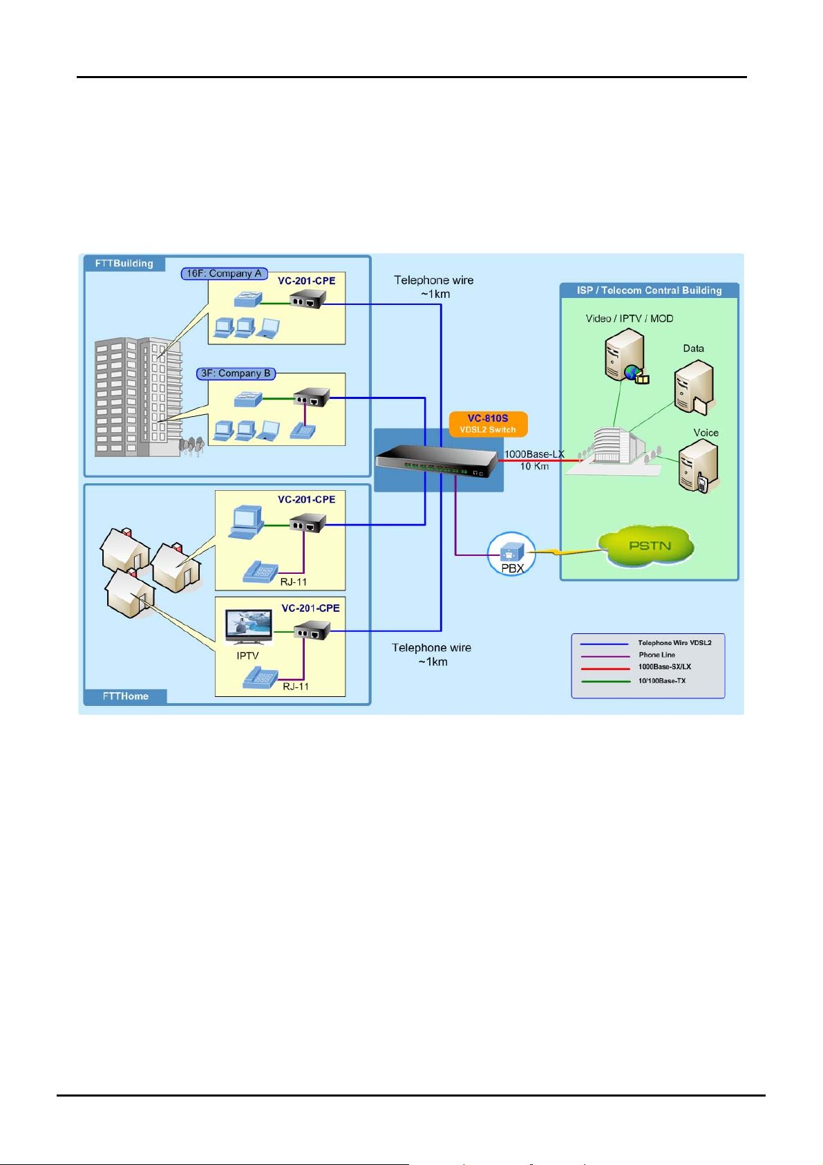
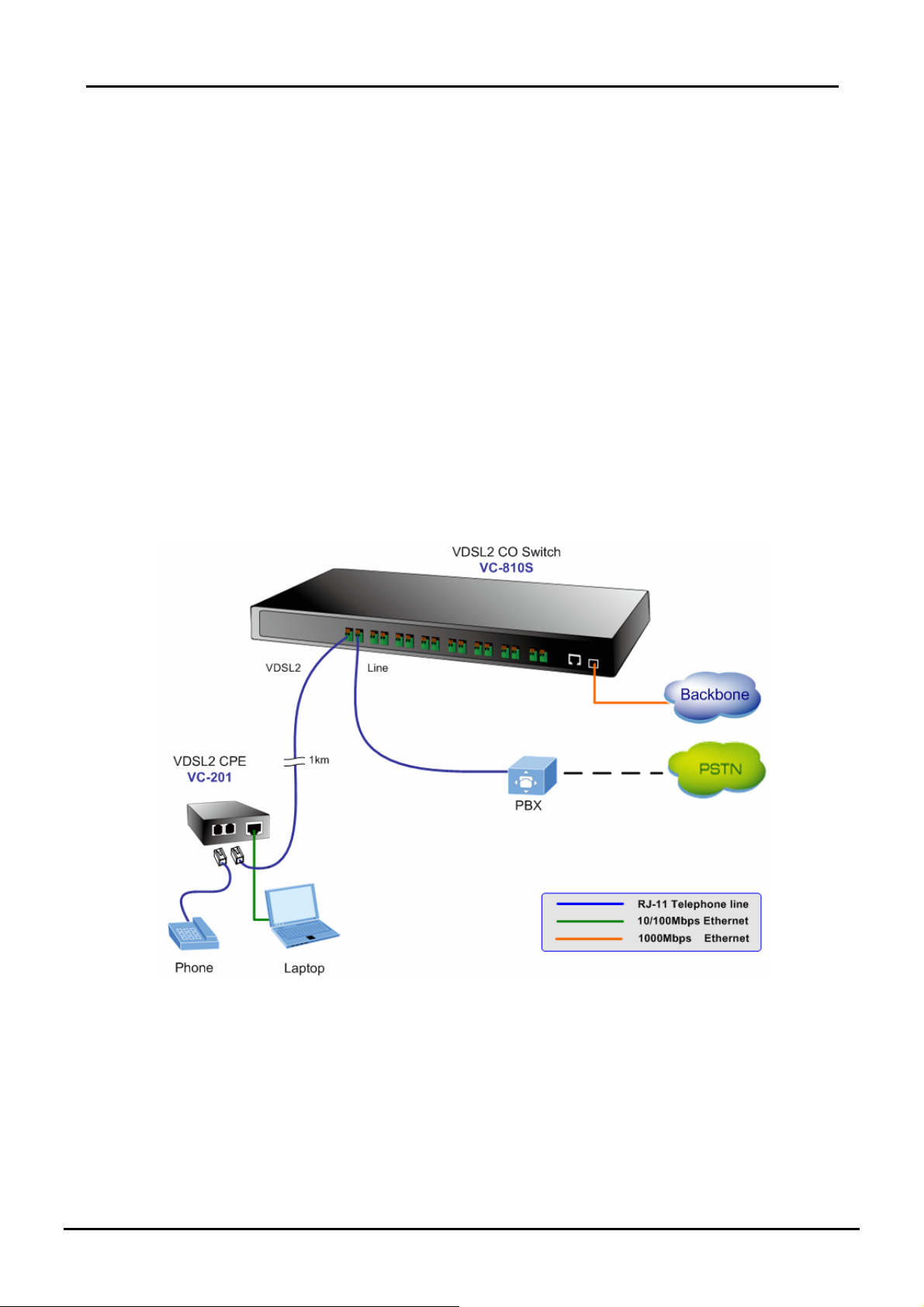
PLANET VC-810S is an 8-Port VDSL2 Manageable CO Switch (Central Office) for Telecom, ISP (Internet Service
Provider), SI (System Integration), IP Surveillance provider and etc. It is based on two core networking technology,
Ethernet and VDSL2 (Very-high-data-rate Digital Subscriber Line 2). Co-works with PLANET developed CPE (Customer
Premises Equipment) – the VC-201, they offers the absolutely fastest data transmission speeds over existing cooper
telephone lines without the need of rewiring. The ideal xDSL technology provides the best solution in the last mile.
The EoVDSL(Ethernet over VDSL) provides up to 100Mbps download capability of VC-810S enables many Multi-Media
services to come true on local Internet, such as IPTV, VOD (Video on Demand), Voice over IP, Video phone, Internet
caching server, distance education, and so on. The VC-810S provides the excellent bandwidth to satisfy the triple play
devices for home entertainment and communication.
Each VDSL2 port of the VC-810S provides two cooper phone wire interfaces–one for VDSL2 connection and the other
one for POTS (Plain Old Telephone Service) connection. To share the existing phone line with POTS, the VC-810S has
built-in POTS splitter that helps the voice of telephone and data of network applications transmitting at the same wire
without interrupted.
The VDSL2 Switch contains robust QoS features such as Port-Based, 802.1p priority and also IP TOS/DSCP; it
guarantees the best performance at VoIP and Video stream transmission and empowers the enterprises to take full
advantages of the limited network resources.
Through the Web management interface, administrator can control the data transmit speed of each VDSL2 interface.
Telecom and ISP can immediately and remotely upgrade/downgrade bandwidth service by different demand.
5
Page 6
User’s Manual of VC-810S / VC-810S48
The VDSL2 Switch contains an advanced management capability that can be remotely accessed by Web Browser. It
provides more flexible and more effectively management function via build-in VLAN, QoS(Quality of Service), storm
control, IGMP Snooping and rate control features to optimize network bandwidth and utilization for Service Providers.
Affording the current network to grow and expand, the VC-810S suppo rts standard Simple Ne twork Management Protocol
(SNMP) and can be centralize monitored the lin k status and bandwidth of each VDSL2 interface These features provide a
cost-effective way to manage the devices from the Internet whenever.
The below drawing shows the typical application of the Ethernet over VDSL:
1.3 How to Use This Manual
This Web Smart VDSL2 Switch User Manual is stru ctured as follows:
Sect ion 2, In st all ati o n
It explains the functions of VDSL2 Switch and how to physically install the VDSL2 Switch.
Section 3, Switch Management
It contains information about the how to manage the VDSL2 Switch.
Section 4, Configuration
The section explains how to manage the VDSL2 Switch by Web interface.
Section 5, Switch Operation
The section explains the basic Layer 2 theories and functions.
Appendices
It contains cable information of the VD SL2 Switch.
6
Page 7

User’s Manual of VC-810S / VC-810S48
1.4 Product Features
VDSL2 Interfaces
8 x Spring terminal block connectors for VDSL2 connection
8 x Spring terminal block connectors for telephone/POTS connection
Built-in POTS splitter for each VDSL2 port
Link to VC-201 CPE Bridge
Auto-speed function for VDSL2 link (by distance and cable quality)
Ethernet Interface
1-Port Gigabit TP/SFP combo interface
Auto-MDI/MDI-X detection on Gigabit RJ-45 port
VDSL2 Features
Cost-effect VDSL2 link and central management solution
ITU-T G.993.2 VDSL2 standard
DMT (Discrete Multi-Tone) line coding VDSL
Up to 100/55Mbps asymmetric data rate
Copper wiring distance up to 1km
Selectable target data rate and target SNR margin
Build-in surge protection to against surge damage from high energy spike
Voice and data communication can be shared on the existing telephone wire simultaneously
Layer 2 Features
Complies with IEEE 802.3 10Base-T, IEEE 802.3u 100Base-TX, IEEE 802.3z 1000Base-SX /LX, IEEE 802.3ab
1000Base-T, IEEE 802.3x flow control, IEEE 802.1Q VLAN and 802.1p priority queuing
8K MAC address table, auto-ageing, 3.6Gbps backbone
IEEE 802.3x Full-duplex flow-control, back-pressure in half-duplex eliminate packets loss
High performance Store and Forward architecture, broadcast storm control, runt/CRC filtering eliminates
erroneous packets to optimize the network bandwidth
IEEE 802.1Q Tagged based VLAN and Port-Based VLAN
IEEE 802.1Q Tagged VLAN, supports tag insertion and removal, and up to 32 VLAN groups
Support up to 2 Trunk groups, each trunk for up to maximum 4 ports per group
Quality of Service
2 priority queues on all switch ports
Support QoS and bandwidth control (Rate Limit) on each VDSL port and GbE port
Traffic class assignment based on IP TOS/DSCP mode, 802.1p priority tag mode and Port-Based mode
Support for strict priority and Weighted Round Robin (WRR) CoS policies
Multicast
IGMP Snooping v1 and v2
Security
Port mirroring for dedicated port monitoring
MAC address based port security, unknown source MAC address will be ignored on a specified port
7
Page 8
Management
WEB-based management
SNMP v1, v2c interface monitor*
SNMP Trap for VDSL port link up and link down status alarm.
48VDC power input for telecom installation ( VC-810S48)
Reset Button for system reset and Reset to factory default
Firmware upgrade by TFTP file transfer protocol through Ethernet network
Port Description (Double bit column)
PLANET Smart Discovery Utility for deploy management
EMI standards comply with FCC, CE class A
*Future Released Features
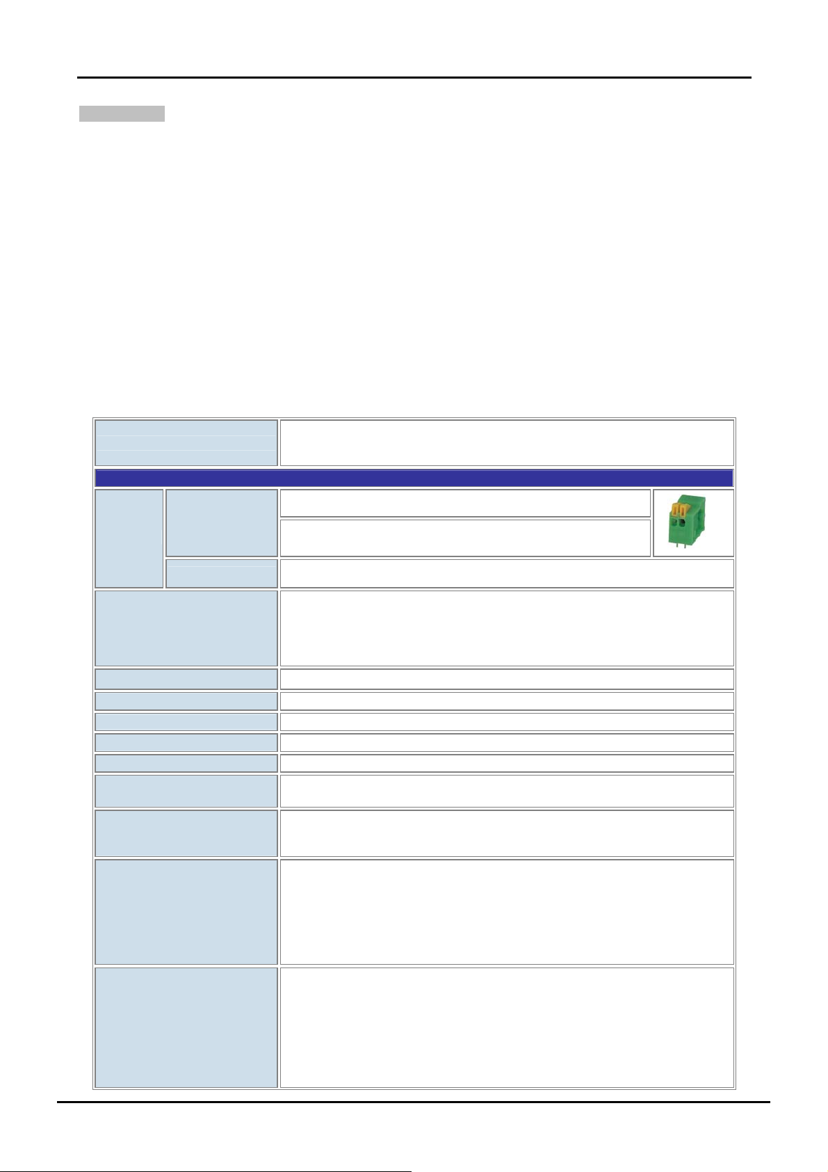
1.5 Product Specification
User’s Manual of VC-810S / VC-810S48
Product
Hardware Specification
VDSL
Interface
Ethernet
VDSL2 Features
Switch Architecture
Switch Fabric
Address Table
Share Data Buffer
Maximum Frame Size
Flow Control
LED
Cables
VC-810S / VC-810S48
8-Port VDSL2 + 1-Port Gigabit TP/SFP Web Smart CO Switch
8-Port VDSL2, 2-Pin screwless spring terminal block connectors
8-Port POTS/Telephone, 2-Pin screwless spring terminal block
connectors
1-Port Gigabit TP/SFP Combo interface, Auto-negotiation, Auto MDI/MDI-X
Selectable Fast and Interleaved mode
Selectable target data rate
Selectable target SNR (signal to Noise Ratio) mode
POTS voices pass through
Surge protected up to 8KV
Store-and-Forward
3.6Gbps / non-blocking
8K entries
1.25Mbit
1536 Bytes packet size
Back pressure for Half Duplex
IEEE 802.3x Pause Frame for Full Duplex
System: Power, Status
VDSL: Data Active, VDSL Link/Sync.
Gigabit Port: 1000 Link/Active, 100 Link/Active
。 VDSL2: twisted-pair telephone wires (AWG24 or better) up to 1km
。 10Base-T: 2-Pair UTP Cat.3,4,5 up to 100m (328ft)
。 100Base-TX: 2-Pair UTP Cat.5, up to 100m (328ft)
。 1000Base-T: 4-pair UTP Cat 5, up to 100m
。 1000Base-SX: 50/125 and 62.5/125 fiber-optic cable, up to 550m
。 1000Base-LX: 9/125 fiber optic cable, up to 10km 50/125 and 62.5/125
fiber-optic cable, up to 550m
• Full VDSL2 Down Stream / Up Stream bandwidth up to:*
。 200m -> 100/55Mbps
Performance / Distance
(Based on AWG26 wires)
8
。 400m -> 85/36Mbps
。 600m -> 60/11Mbps
。 800m -> 40/5Mbps
。 1000m -> 30/1Mbps
Page 9
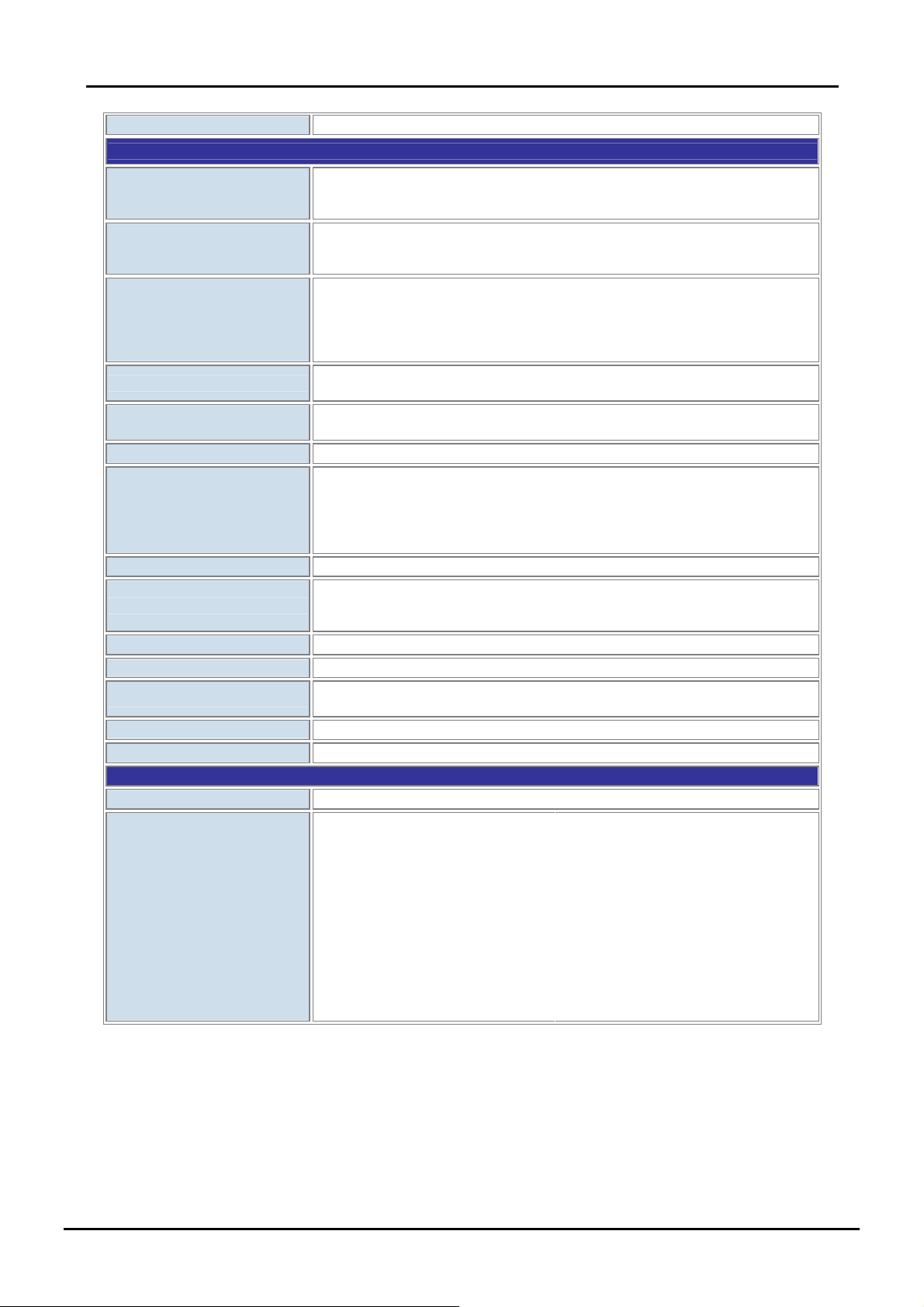
Button
Layer 2 Function
Management Interface
Port Configuration
Port Status
Port Statistics
VLAN
Link Aggregation
QoS
IGMP Snooping
Bandwidth Control
Port Mirror
Security
SNMP MIBs
Others
MAC Address Table
Standards Conformance
Regulation Compliance
User’s Manual of VC-810S / VC-810S48
Reset Button for system reset and Reset to factory default
Web Browser,
SNMP v1 and v2c, SNMP Trap*
PLANET Smart Discovery Utility
Port Enable / Disable.
Flow Control Enable / Disable.
Bandwidth control on each port.
VDSL2:
Display each port’s Status, Mode, Rate Limit and SNR
Gigabit Ethernet interface:
Display each port’s speed duplex mode, link status, Flow control status. Auto
negotiation status
。 TX/RX packet/byte
。 CRC error
Port-Based VLAN: up to 9 VLAN groups
IEEE 802.1Q Tagged Based VLAN: 4094 VLAN ID, up to 32VLAN groups
Supports 2 groups of 4-Port trunk
2 priority queues for three type of Class of Service
• Port-Based
• IEEE 802.1p priority tag
• TCP/IP header’s TOS/DSCP classifier
Weighted Round Robin queue scheduling
v1 and v2, allow to disable or enable.
Per port bandwidth control
Downstream: 1Mbps~100Mbps
Upstream: 1Mbps~60Mbps
RX or TX
Port Security (Per Port Disable MAC Address Learning )
RFC-1213 MIB-II
RFC-2863 Interface MIB
SNTP Client
Aging time: selectable Default Mode (300 Sec.) and Fast Mode (30 Sec.)
FCC Part 15 Class A, CE
IEEE 802.3 10BASE-T
IEEE 802.3u 100BASE-TX
IEEE 802.3z Gigabit SX/LX
IEEE 802.3ab Gigabit 1000T
IEEE 802.3x Flow Control
Protocols and Standards
Compliance
* The actual data rate will vary on the quality of the copper wire or coaxial cable and environment factors.
9
IEEE 802.1p Class of service
IEEE 802.1Q VLAN Tagging
ITU-T
G.993.1 (VDSL)
G.997.1
G.993.2 VDSL2 (Profile 12a
Support), Annex A
RFC 768 UDP
RFC 793 TFTP
RFC 791 IP
RFC 792 ICMP
RFC 2068 HTTP
RFC 2030 SNTP
RFC 1112 IGMP versions 1
RFC 2236 IGMP versions 2
Page 10
User’s Manual of VC-810S / VC-810S48
2. INSTALLATION
This section describes the hardware features and installation of these VDSL2 Switches on the desktop or rack mount. For
easier management and control of the VDSL2 Switch, fa miliarize yourself wi th its display indicators, and po rts. Front panel
illustrations in this chapter display the unit LED indicators. Before start to deploy the VDSL2 Switch, please read this
chapter completely.
2.1 Hardware Description
2.1.1 Switch Front Panel
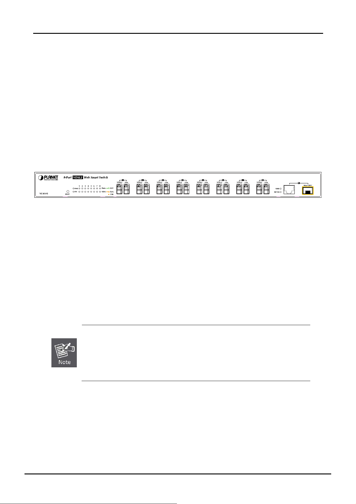
The unit front panel provides a simple in terface monito ring the VD SL2 Sw itch. Fig ure 2-1 show s a front p anel o f VC-810S
/ VC-810S48.
Figure 2-1 PLANET VC-810S / VC-810S48 Front Panel
■ VDSL2 and POTS interface (Port-1~Port-8)
There are 8 VDSL2 ports and 8 POTS ports with Screw less Spring Terminal Block connector on the front panel. The
advantage of Screw less Spring Terminal Block connector is no need to fabricate RJ-11 type phone connector in the
Equipment Room. And no need extra phone line patch panel. Each port is built-in POTS splitter that helps the voice of
telephone and data of network applications transmitting at the same wire without interrupted.
The VDSL2 supports auto detection transmission rate that operate in different band allocation and result in different
upstream and downstream bandwidth.
And Due to different telephone line quality, cross talk or extension distance may affect actual achievable speed; you can
configure individual port in built-in management interface for optimized connectivity.
1. The payload rate is about 9% less than the line rate due to framing overhead.
2. AWG 26 (0.4mm) cable can also be used but the distance is 20% to 40% shorter than
above table.
3. Each terminated b ri dg e t ap ca n r e duc e th e VDSL link distance by 90m.The quality of the
cable, the size of the cable bundles, and the cross talk within the bundle, can also affect
other overall reach.
■ Gigabit TP / SFP Combo interface (Port-9)
The one Gigabit TP/SFP combo interface provides the below link mode:
• 10/100/1000Base-T Copper, RJ-45 Twist-Pair: Up to 100 meters.
• 1000Base-SX/LX mini-GBIC slot, SFP (Small Factor Pluggable) transceiver module: From 550 meters
(Multi-mode fiber), up to 10/30/50/70/120 kilometers (Single-mode fiber).
10
Page 11
User’s Manual of VC-810S / VC-810S48
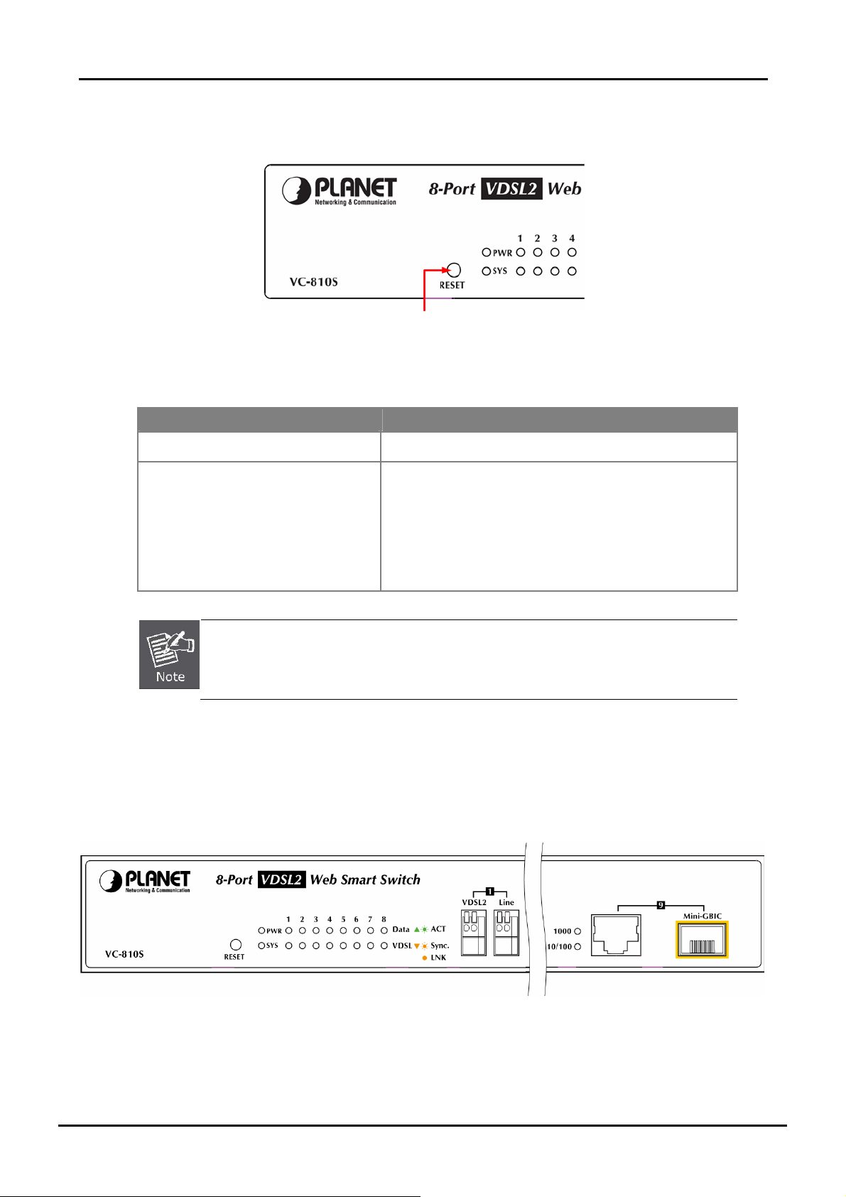
■ Reset button
At the left of front panel, the reset button is designed for reboot the VDSL2 Switch without turn off and on the power.
Figure 2-2 Reset button of VC-810S / VC-810S48
The following is the summary table of Reset button functions:
Reset Button Pressed and Released Functio n
About 1 second Reboot the VDSL2 Switch.
Reset the VDSL2 Switch to Factory Default configuration.
The VDSL2 Switch will then reboot and load the default IP.
Until the SYS LED lit off
settings as below:
。 Default Password: admin
。 Default IP address: 192.168.0.100
。 Subnet mask: 255.255.255.0
。 Default Gateway: 192.168.0.254
To press the RESET button about 10 seconds and then release. The VDSL2 Switch will back to
the factory default m ode . Be sur e th at yo u b ac ku p th e c ur r ent c o nf i gur at i o n of VDS L2 Swit c h;
else the entire configuration will be erased when pressing the “RESET” button.
2.1.2 LED Indicators
The front panel LEDs indicates instant status of port links, data activity, system operation and system power, helps
monitor and troubleshoot when needed.
Figure 2-3 PLANET VC-810S / VC-810S48 LED panel
11
Page 12
■ System
LED Color Function
PWR Green
SYS Orange Lit: Lights to indicate the system is working.
■ Per VDSL Interface ( Port-1 to Port-8)
LED Color Function
Data ACT Green
User’s Manual of VC-810S / VC-810S48
Lit: Indicate that the VDSL2 Switch is powered on.
Off: Indicate that the VDSL2 Switch is powered off.
Blink:
Indicate that the DATA link is actively sending or receiving data
over that VDSL port.
Off: Indicate that the port is link down or no data active on this port.
Lit: Indicate that the VDSL link is established.
Blink: Indicate that the VDSL is at training status with remote CPE.
Off: Indicate that the VDSL is link down.
Lit: Indicate that the port is link up.
Blink: Indicate that the VDSL2 Switch is actively sending or recei ving data
Off: Indicate that the port is link down or operate at 10Mbps or 100Mbps.
Lit: Indicate that the port is operating at 100Mbps or 10Mbps.
Blink: Indicate that the VSL2 Switch is actively sending or receiving data
Off: Indicate that the port is link down or 1000Mbps.
VDSL
LNK/Sync
■ 10/100/1000Base-T Copper / 1000Base-SX/LX SFP Interface (Port-9)
LED Color Function
1000
LNK/ACT
10/100
LNK/ACT
Orange
Green
Orange
2.1.3 Switch Rear Panel
over that port.
over that port.
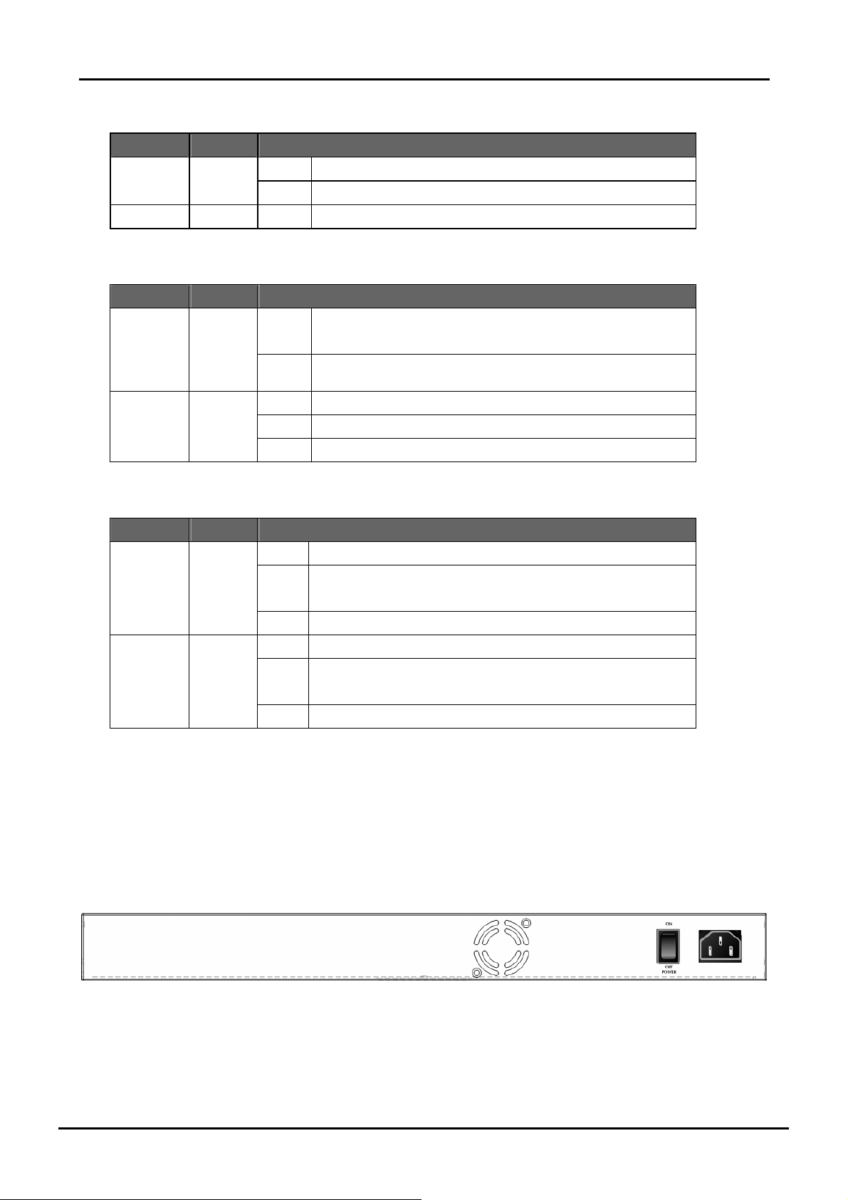
■ VC-810S
The rear panel of the VC-810S contains a power switch and an AC inlet power socket, which accepts input power from
100 to 240VAC, 50-60Hz.
Figure 2-4 Rear Panel of VC-810S
12
Page 13
User’s Manual of VC-810S / VC-810S48
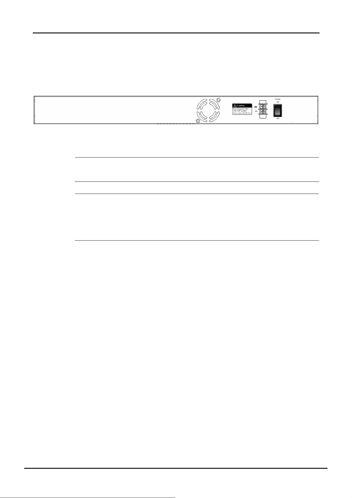
■ VC-810S48
The rear panel of the VC-810S48 contains a power switch and a DC power connector, which accepts DC power input
voltage from -30V to -60V DC. Connect the power cable to the Switch at the input terminal block. The size of the two
screws in the terminal block is M3.5.
Figure 2-5 Rear Panel of VC-810S48
Warning:
Power
Notice:
Before connect the DC power cable to the input terminal block of VC-810S48, ensure that the power
switch in the “OFF” position and the DC power is OFF.
1. The device is a power-required device, it means, it will not work till it is powered. If your networks
should active all the time, please consider using UPS (Uninterrupted Power Supply) for y ou r device .
It will prevent you from network data loss or network downtime.
2. In some area, in stalling a surge suppression de vice may also help to protect y our VDSL2 Sw itchfrom
being damaged by unregulated surge or current to the Switch or the power adapter.
13
Page 14
User’s Manual of VC-810S / VC-810S48
2.2 Install the Switch
This section describes how to install your VDSL2 Switch and make connections to the VDSL2 Switch. Please read the
following topics and perform the procedures in the order being presented. To install your VDSL2 Switch on a desktop or
shelf, simply complete the following steps.
2.2.1 Desktop Installation
To install VDSL2 Switch on a desktop or shelf, simply complete the following steps:
Step1: Attach the rubber feet to the recessed areas on the bottom of the VDSL2 Switch.
Step2: Place the VDSL2 Switch on a desktop or shelf near an AC power source.
Step3: Keep enough ventilation space between the VDSL2 Switch and the surrounding objects.
When choosing a location, please keep in mind the environmental restrictions discussed in
Chapter 1, Section 4, and Specification.
Step4: Connect your Switch to network devices.
A. Connect one end of a standard network cable to the 10/100/1000 RJ-45 ports on the front of the Gigabit
Ethernet Switch.
B. Connect the other end of the cable to the netw ork devices such as printer servers, workstations o r routers…etc.
Connection to the VDSL2 Switch requires UTP Category 5 network cabling with RJ-45 tips.
For more informatio n , p lea s e se e th e C ab l in g Sp ec if i c at i on in Appendix A.
Step5: Supply power to the Switch.
A. Connect one end of the power cable to the VDSL2 Switch.
B. Connect the power plug of the power cable to a standard wall outlet.
When the VDSL2 Switch receives power, the Power LED should remain solid Green.
2.2.2 Rack Mounting
To install the VDSL2 Switch in a 19-inch standard rack, please follows the instructions described below.
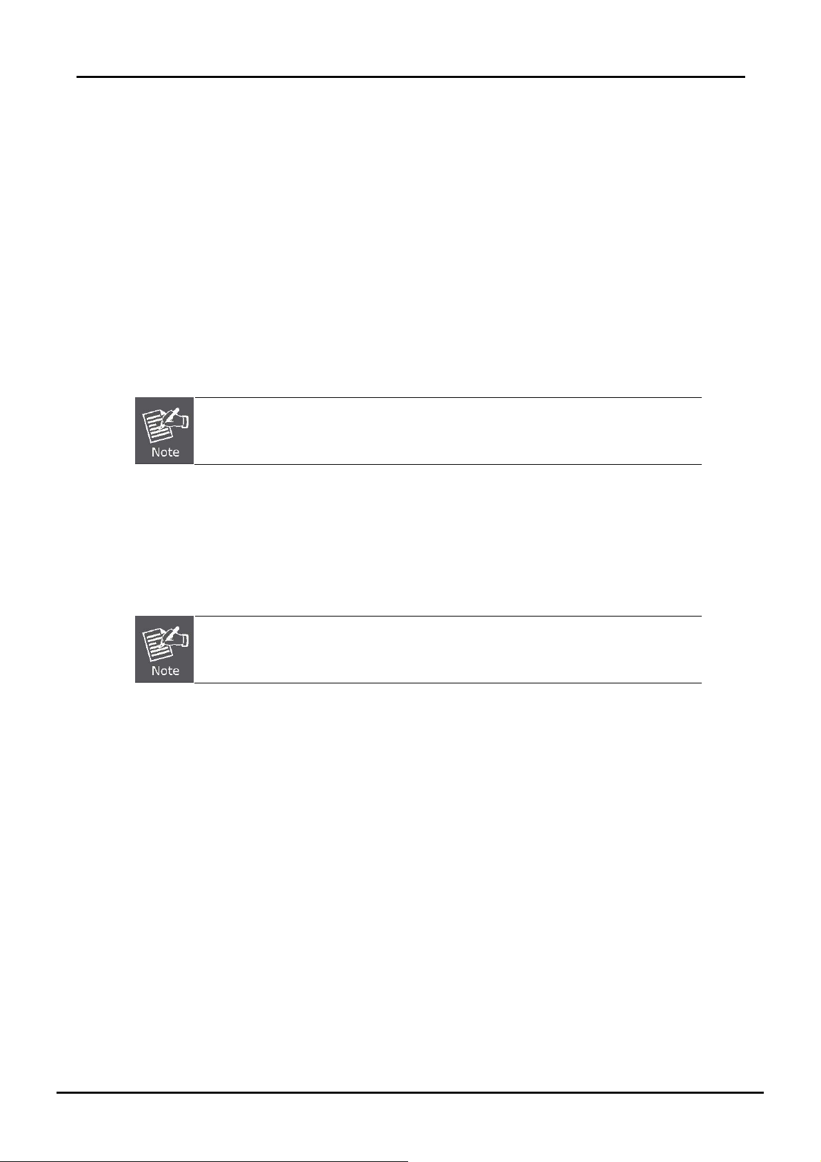
Step1: Place the VDSL2 Switch on a hard flat surface, with the front panel positioned towards the front side.
Step2: Attach the rack-mount bracket to each side of the VDSL2 Switch, with supplied screws attached to the package.
Figure 2-6 shows how to attach brackets to one side of the VDSL2 Switch.
14
Page 15
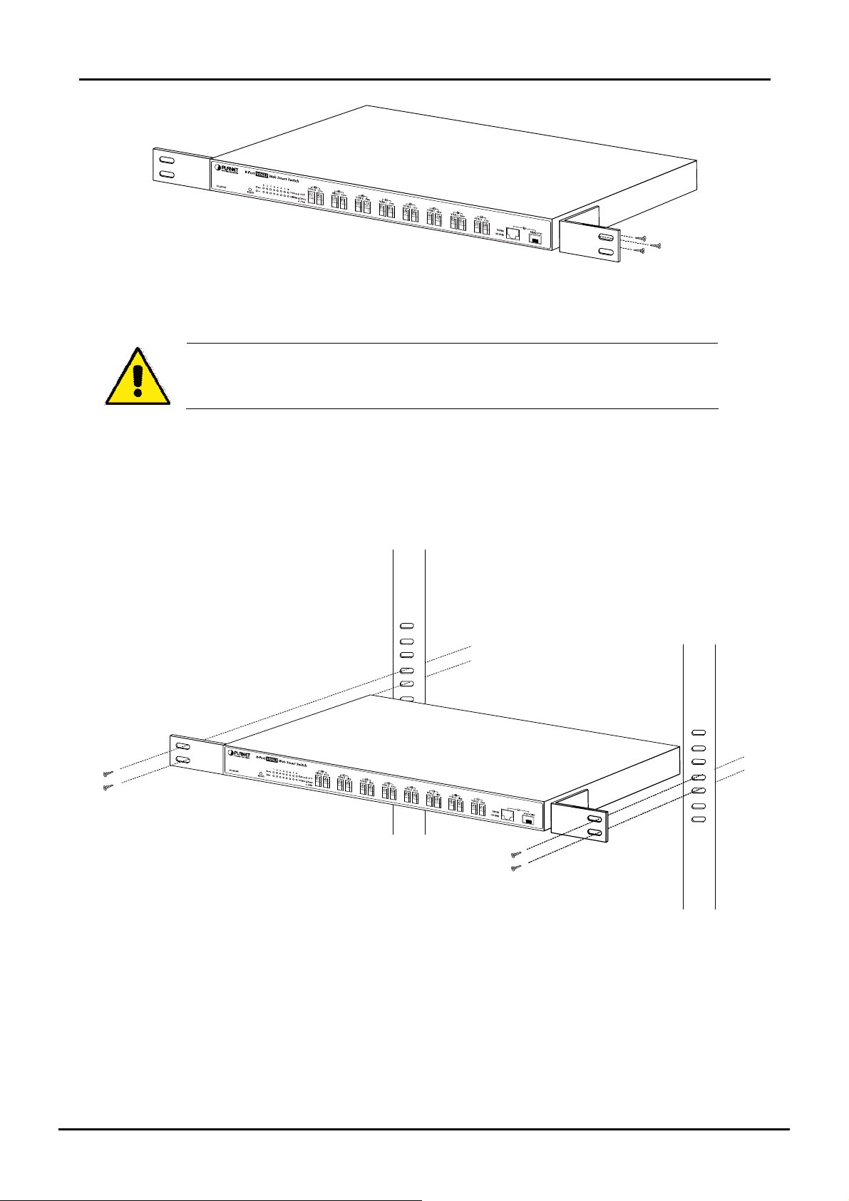
Figure 2-6 Attach brackets to the VDSL2 Switch
You must use the screws supplied with the mounting brackets. Damage caused to the parts
by using incorrect screws would inval id at e t he war r a nt y.
Step3: Secure the brackets tightly.
Step4: Follow the same steps to attach the second bracket to the opposite side.
User’s Manual of VC-810S / VC-810S48
Step5: After the brackets are attached to the VDSL2 Switch, use suitable screws to securely attach the brackets to the
rack, as shown in Figure 2-7.
Figure 2-7 Mounting the VDSL2 Switch in a Rack
Step6: Proceeds with the steps 4 and steps 5 of sessio n 2.2.1 Desktop Installation to connect the network cabling and
supply power to the VDSL2 Switch.
15
Page 16
User’s Manual of VC-810S / VC-810S48
2.2.3 Installing the SFP transceiver
The sections describe how to insert an SFP transceiver into an SFP slot.
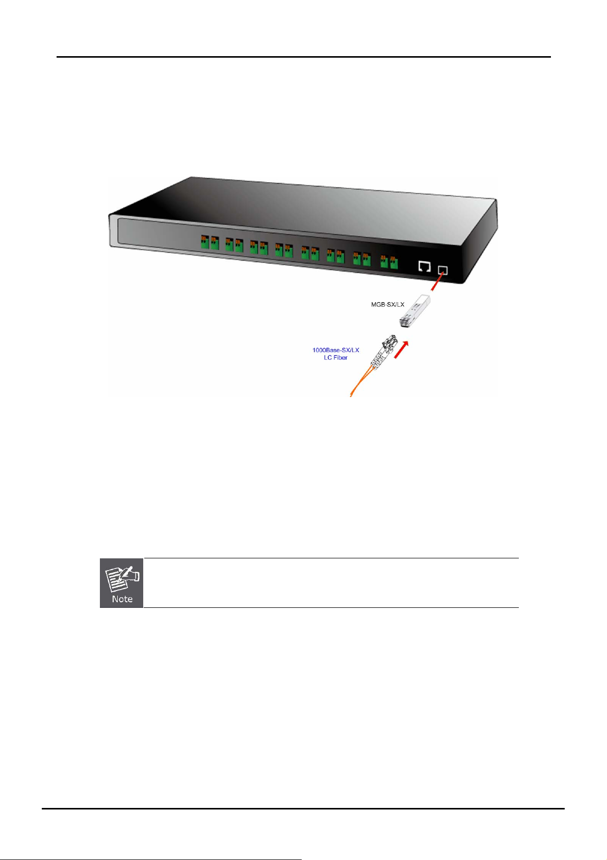
The SFP transceivers are hot-pluggable and hot-swappable. You can plug-in and out the transceiver to/from any SFP port
without having to power down the VDSL2 Switch. As the Figure 2-8 appears.
Figure 2-8 Plug-in the SFP transceiver
Approved PLANET SFP Transceivers
PLANET VDSL2 Switch supports both single mode and multi mode SFP transceiver. The following list of approved
PLANET SFP transceivers is correct at the time of publication:
■MGB-SX SFP (1000Base-SX SFP transceiver )
■MGB-LX SFP (1000Base-LX SFP transceiver )
It recommends using PLANET SFP transceiver on the VDSL2 Switch. If you insert a SFP
transceiver that is not supported, the VDSL2 Switch will not recognize it.
Before connect the other switches, workstation or Media Converter.
1. Make sure both side of the SFP transceiver are with the same media type, for example: 1000Base-SX to
1000Base-SX, 1000Bas-LX to 1000Base-LX.
2. Check the fiber-optic cable type match the SFP transceiver model.
¾ To connect to 1000Base-SX SFP transceiver, use the multi-mode fiber cable- with one side must be male
duplex LC connector type.
¾ To connect to 1000Base-LX SFP transce i ver , us e t he single-mode fiber cable-with one side must be male
duplex LC connector type.
16
Page 17
User’s Manual of VC-810S / VC-810S48
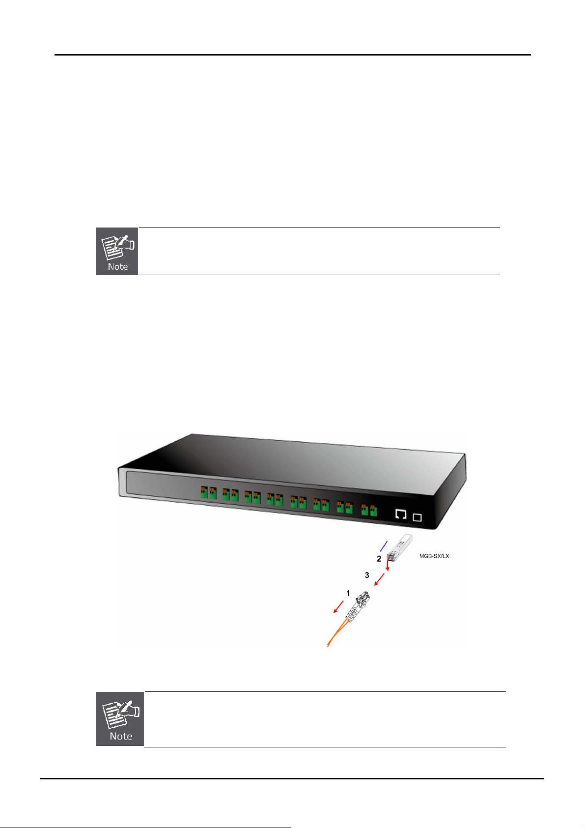
Connect the fiber cable
1. Attach the duplex LC connector on the network cable into the SFP transceiver.
2. Connect the other end of the cable to a device – switches with SFP installed, fiber NIC on a workstation or a Media
Converter..
3. Check the LNK/ACT LED of the SFP s lot on the front of the VDSL2 Switch. Ensure that the SFP transceiver is
operating correctly.
4. Check the Link mod e of the S F P por t if t he l i nk f ai led . Co works with some fiber-NICs or Media Converters, set the
Link mode to “1000 Force” is needed.
There is a known SFP operation issue, please insert the transceiver into the SFP slot first.
Then connect the fiber cable, or the Fiber link might be failed.
Remove the tran sceiver module
1. Make sure there is no network activity by consult or check with the network administrator. Or through the
management interface of the switch/converter (if available) to disable the port in advance.
2. Remove the Fiber Optic Cable gently.
3. Turn the handle of the MGB/MFB module to horizontal.
4. Pull out the module gently through the handle.
Figure 2-9 Pull out the SFP transceiver
Never pull out the module without pull the handle or the push bolts on the module . Direct pull
out the module with violent could damage the module and SFP module slot of the VDSL2
Switch.
17
Page 18
User’s Manual of VC-810S / VC-810S48
2.2.4 Wiring for VDSL ports
The VDSL2 ports of VC-810S / VC-810S48 use Screwless Spring Terminal Block connector to connect to 8 VDSL2
Converters (VC-210- Ethernet over VDSL2 Media Converter) through structured or unstructured wiring, such as existing
telephone lines. The advantages of Screwless Terminal Block as below:
- Fast and maintenance-free connection regardless of the skills of the installer
- Vibration and shock resistant
The link between the VDSL2 Switch port and each Converter can reach speeds of u p to 100/55 Mbps o ver distances of up
to1km. The network manager or ISP/Telecom operator can hot swap the VDSL2 Converters without powering down the
VDSL2 Switch or disrup ti n g t he ot h e r S wit c h por ts.
If telephone services, such as voice or Fax, use the same cabling as VDSL2 traffic, the VDSL2 port is built-in POTS (Plain
Old Telephone Service) splitter that helps the voice of telephone and data of network applications transmitting at the same
wire without interrupted. The splitter routes VDSL2 data (high-frequency) and voice (low-frequency) traffic from the
telephone line to the VDSL2 Switch and private branch exchange (PBX) switch or public switched telephone network
(PSTN).
The connection diagram is as the following:
Figure 2-10 VDSL2 link diagram
If the port is connected but the relevant LED is dark, check the following items:
1. The VDSL2 Switch and the connected device’s power are on or not.
2. The connecting cable is good and with correct type.
3. The cable is firmly seated in its connectors in the Switch and in the associated device.
4. The connecting device, including any network adapter is well installed and functioning.
5. Confirm the CPE (VC-201) is set to CPE mode. Check the DIP switch at the rear panel.
6. Confirm the CPE (VC-201) device is implemented within the scope of operative without inter f er e nce .
18
Page 19
User’s Manual of VC-810S / VC-810S48
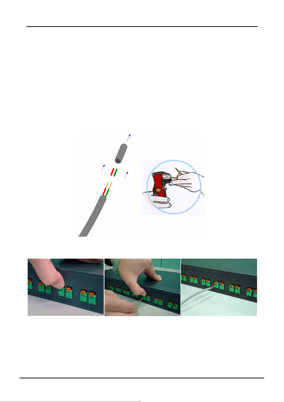
Connecting the 2-Pair telephone wire
1 Using a wire cutter, cut off the bare wire just below the plastic insulation on all two wires.
2 Then use a wire stripper to strip off about 1cm (1/2”) of the insulation from both ends of each wire. As the Figure 2-11
appears.
3 Some trial and error may be necessary to ensure the insula tion is cu t and no t the w ire w hen i t i s placed i n the no tch of
the cutting blades.
4 This will give you a clean piece of wire for the new connection to the Screwless Terminal Block connector. As the
Figure 2-12 appears.
5 The 'pu sh-in' design allows tool-less insertion of twist phone wires.
6 If needed, strip the wires that are already attached to the VDSL2 ports of the VDSL2 Switch.
Figure 2-11 Use a wire stripper to stripe the telephone wire
Figure 2-12 Tools-less push-in design
19
Page 20
User’s Manual of VC-810S / VC-810S48
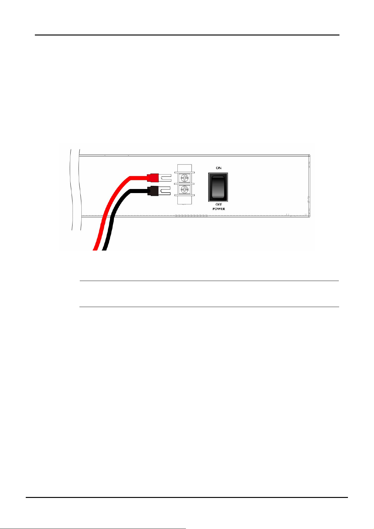
2.2.5 Connecting DC Power Supply
The VC-810S48 support -48VDC power input, connect the power cable to the VDSL2 Switch at the input terminal block.
1 The size of the two screws in the terminal block is M3.5.
2 The terminals are marked “-48V”, “FG“.
3 Loosen the two screws so you can slide the DC cable beneath it. Insert the DC cable into the connector first, and
screw it down tight.
4 Connect the power cable to the DC power supply. After power up or reset, the VC-810S48 performs a cold start
procedure.
Warning:
Figure 2-13 -48VDC connector
Before connect the DC power cable to the input terminal block of VC-810S48, ensure that the power
switch in the “OFF” position and the DC power is OFF
20
Page 21

User’s Manual of VC-810S / VC-810S48
3. SWITCH MANAGEMENT
This chapter describes how to manage the VDSL2 Switch. Topics include:
- Overview
- Management methods
- Assigning an IP address to the VDSL2 Switch
- Logging on to the VDSL2 Switch
3.1 Overview
This chapter gives an overview of switch management. The VDSL2 Switch provides a simply WEB browser interface.
Using this interface, you can perform various switch configuration and management activities, including:
System
Port Management
VLAN
Quality of Service
Multicast
Address Learning Table
Port Mirroring
Link Aggregation
Statistics
Storm Control
Please refer to the following Chapter 4 for more details.
3.2 Requirements
■ Network cables.
Use standard network (UTP) cables with RJ45 connectors.
■ Subscriber PC installed with Ethernet NIC (Network Card)
■ Workstations of subscribers running Windows 98/ME, NT4.0, 2000/2003/XP, MAC OS X or later, Linux, UNIX or
other platform compatible with TCP/IP protocols.
■ Above PC installed with WEB Browser and JAVA runtime environment Plug-in.
It is recommended to use Internet Explore 6.0 or above to access VDSL2 Switch.
21
Page 22
User’s Manual of VC-810S / VC-810S48
3. 3 Management Methods
The way to manage the VDSL2 Switch:
- Web Management via a network or dial-up connection.
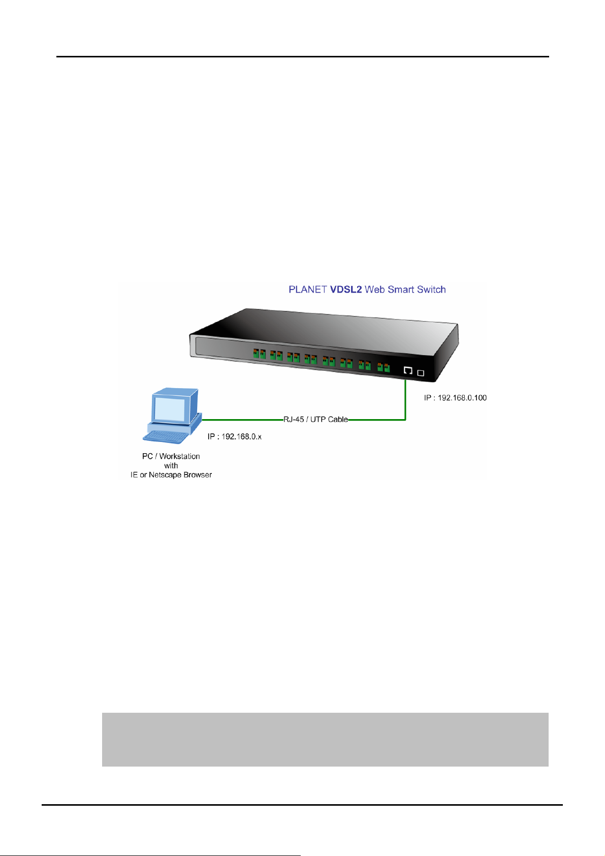
3.3.1 Web Management
The PLANET VDSL2 Switch provides a built-in browser interface. You can manage the VDSL2 Switch remotely by having
a remote host with web browser, such as Microsoft Internet Explorer, Netscape Navigator or Mozilla Firefox.
Using this management method:
The VDSL2 Switch must have an Internet Protocol (IP) address accessible for the remote host.
Figure 3-1 Web Management over Ethernet
3.3.2 Login the Switch
The following shows how to startup the Web Management of the VDSL2 Switch, please note the VDSL2 Switch is
configured through an Ethernet connection, make sure the manager PC must be set on the same IP subnet address.
For example, the default IP address of the VDSL2 Switch is 192.168.0.100, then the manager PC should be set at
192.168.0.x (where x is a number between 1 and 254, except 100), and the default subnet mask is 255.255.255.0.
1 Use Internet Explorer 6.0 or above Web browser, enter IP address http://192.168.0.100 (the factory-default IP
address) to access the Web interface.
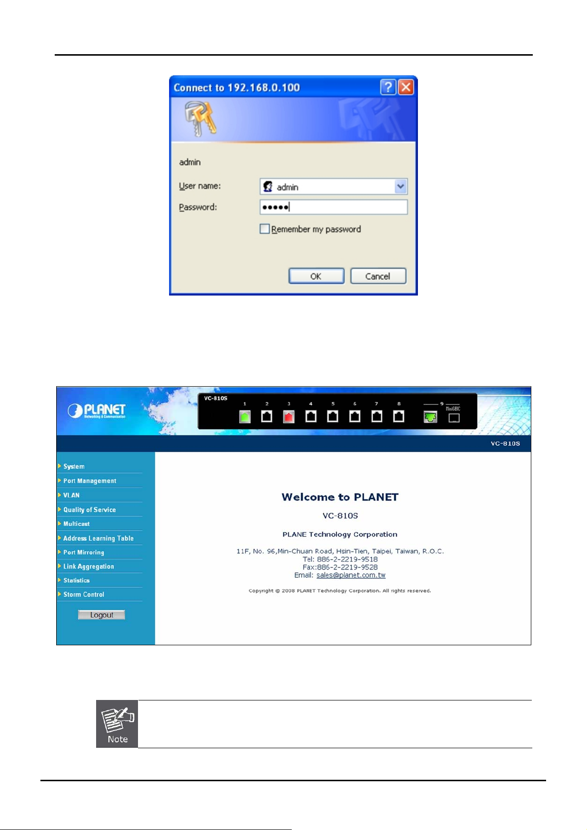
2 When the following login screen appears, please enter the default account and password - "admin" and press Apply
to enter the main screen. The login screen in Figure 3-2 appears.
Default IP Address: 192.168.0.100
Default Account: admin
Default Password: admin
22
Page 23
User’s Manual of VC-810S / VC-810S48
Figure 3-2 Login screen
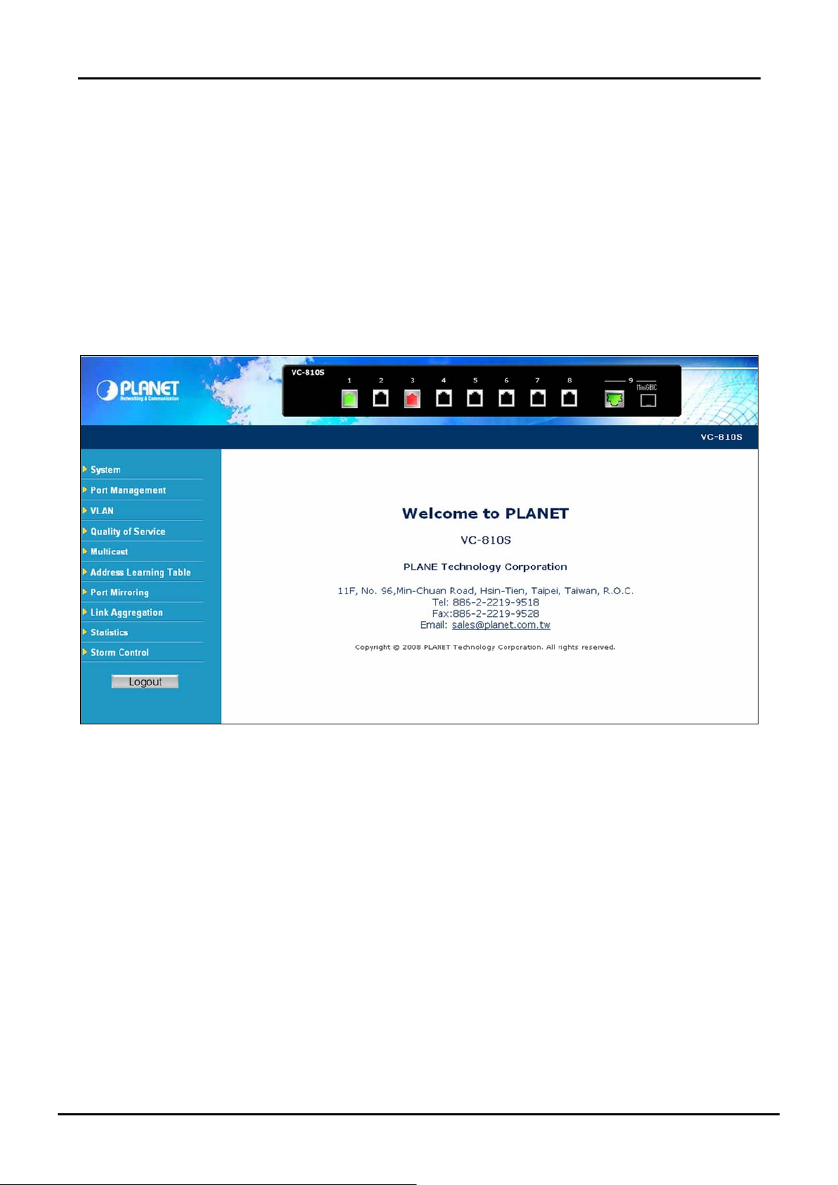
After a successful login, the main screen appears, the main screen displays the Switch status. The screen in Figure3-3
appears.
Figure 3-3 Web Login screen of VDSL2 Switch
1. For security reason, please change and memorize the new password after this first setup.
2. Only accept command in lowercase letter under web interface.
23
Page 24
User’s Manual of VC-810S / VC-810S48
4. CONFIGURATION
The VDSL2 Switch pr ov id e W eb i nt e rf ac e for S wit c h sm ar t f unction configurati o n an d m ak e th e VDS L 2 S witc h op e r at e
more effectively - They can be configured through the Web Browser. A netw ork administrator can manage and monitor the
VDSL2 Switch from the local LAN. This section indica tes how to con figure the VDSL2 Sw itch to enable it s smart function.
4.1 Main Menu
Main menu appears at left side of the WEB browser interface after successfully login VC-810S. To enter any of the
submenus, simply move the cursor to the main function and click. When select further options, the configurable interface
shows at right side. The screen in Figure 4-1 appears.
Figure 4-1 Web Main screen
Via the Web-Management, the administrator can setup the VDSL2 Switch by select the functions those listed in the Main
Function. As listed at the left of the main screen, the configurable smart functions are shown as below:
System –
Port Management VLANs –
Quality of Service –
Multicast –
Address Learning Table –
Port Mirroring Link Aggregation –
Statistics -
Storm Control -
24
Check the hardware, software version and System MAC address. Setting the IP address,
Firmware Update and SNTP management for the VDSL2 Switch.
Setup per VDSL2 port mode, Rate Limit, SNR margin Port description.
Configure VLAN Member / Po rt Co nf i gur at i o n.
Mapping the packet level to classify the packets priority.
Enables or disables IGMP Snooping on the device to filter the multicast stream.
Configure MAC address table aging, aging time mode and 802.1d BPDU packet filter.
Dedicated port monitoring for incoming packets.
Configure link aggregation groups. Up to 4 VDSL2 ports per link trunk group.
Display transmit, receive and CRC packets statistics of each port on the VDSL2 Switch.
Enable Storm Control function to reduce broadcast packets on the VDSL2 Switch.
Page 25
User’s Manual of VC-810S / VC-810S48
4.2 System
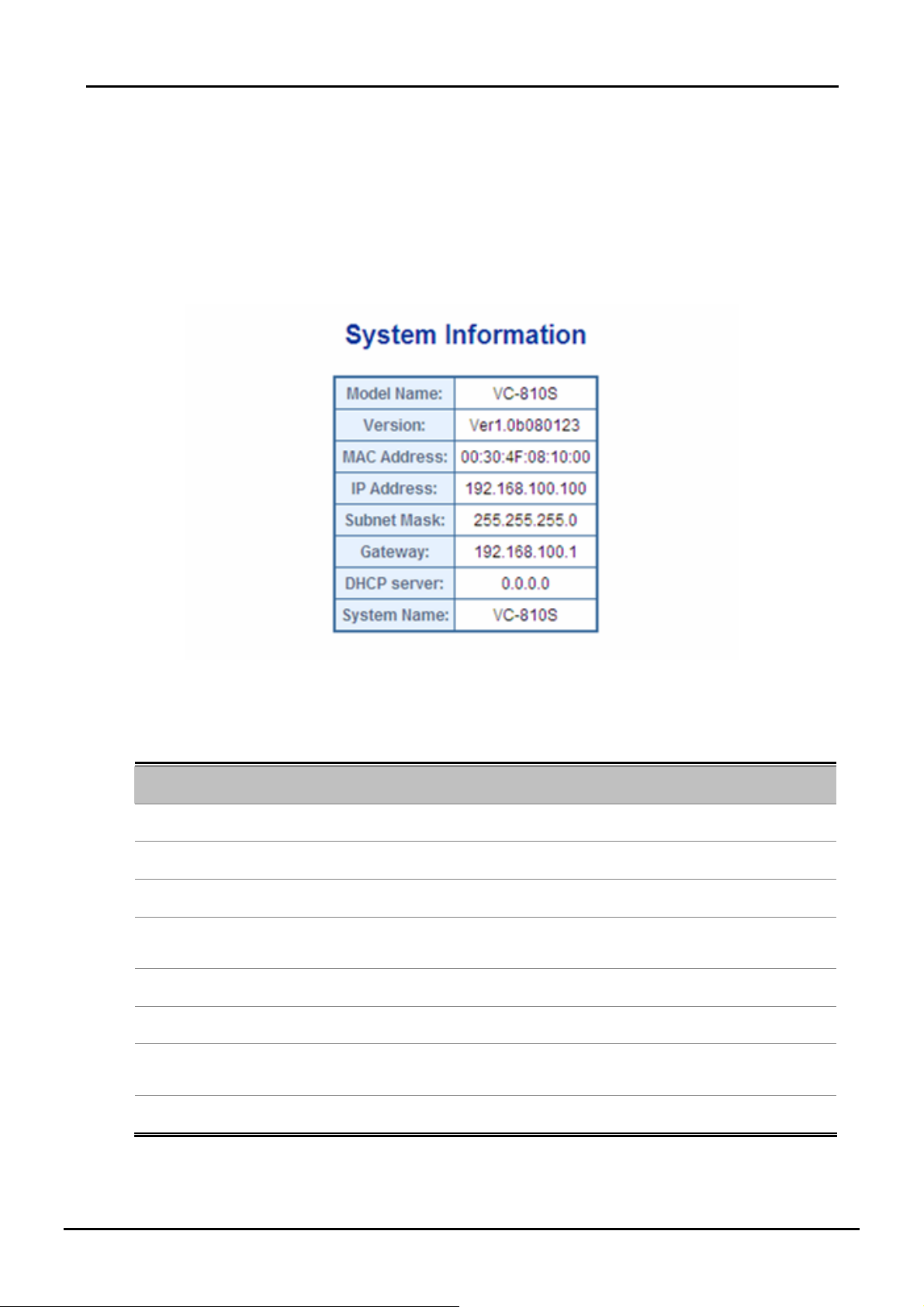
4.2.1 System Information
The System Info page provides information for the current device information. System Info page helps a switch
administrator to identify the Model Name / firmware version / MAC Address and IP subnet address / DHCP server IP
address / System Name. The screen in Figure 4-2 appears.
The page includes the following fields:
Object Description
• Model Name
• Version
• MAC Address
• IP Address
• Subnet Mask
• Gateway
• DHCP Server
Figure 4-2 System Information screen
The product name of this VDSL2 Switch.
The current software version running on the device.
Specifies the device MAC address.
The current IP Address of the device. The IP Address could be manual assigned
or get via DHCP server.
The current IP Subnet Mask setting on the device.
The current IP Gateway of the device.
If the IP address is got and assigned via a DHCP server, the field shows the IP
Address of the DHCP ser v er.
• System Name
25
Display the user- d ef i ne d d ev ice n am e.
Page 26

User’s Manual of VC-810S / VC-810S48
4.2.2 IP Configuration
The IP Configuration includes the IP Address, Subnet Mask, Gateway and DNS server. Through the Web Switch Utility,
you can easily recognize the device by usi ng the Sy stem Name. Fill up the IP Address, Subnet Mask and Gateway for the
device. The screen in Figure 4-3 appears.
Figure 4-3 IP Configuration scr e e n
The page includes the following configurable data:
Object Description
DHCP Mode
IP Address The IP address of the interface. The factory default value is 192.168.0.100
Subnet Mask The IP subnet mask for the interface. The factory default value is 255.255.255.0
Gateway
Primary DNS Enter the IP Address of the P ri m ar y D NS S e rver . T he Domain Name System
Secondary DNS
Choose what the switch should do following power-u p: transmit a DHCP request,
or manual setting (Disable). The factory default is Disable.
The default gateway for the IP interface. The factory default value is
192.168.0.254.
(DNS) converts user-defined domain names into IP addresses.
Enter the IP Address of the Secondary DNS Server.
26
Page 27

User’s Manual of VC-810S / VC-810S48
4.2.3 SNTP Configuration
In the System sub-function menu, you can see the SNTP Configuration (see Figure 4-4), by which you can configure the
time settings for the VDSL2 Switch. You can specify SNTP Servers and select GMT Time zone.
Figure 4-4 SNTP Configuration screen
The Time page includes the following fields:
Object Description
Current Time
Mode Enable: Specifies that the system time is set via an SNTP server.
GMT Time zone
SNTP Server
The device supports the Simple Network Time Protocol (SNTP). SNTP assures accurate
network device clock time synchronization up to the millisecond. Time synchronization is
performed by a network SNTP server. SNTP operates only as a client, and cannot provide time
services to other systems.
Display the current local date and time (U TC) of the last SNTP request or receipt
of an unsolicited message. The field format is Day : Month: HH : MM : SS : Year.
For example, Thu Jan 21:15:03 GMT 2008.
Disable: Specifies that the system time is not set by an external source.
The difference between Greenwich Mean Time (GMT) and local time. For
example, the Time Zone Offset for Paris is GMT +1, while the lo cal time in Taipe i
is GTM +8.
Enter a user-defined SNTP server IP addresses or hostname. This is a text string
of up to 64 characters containing the en coded unicast IP address or ho stname of
a SNTP server. Unicast SNTP requests will be sent to this address. If this
address is a DNS hostname, then that hostname should be resolved into an IP
address each time a SNTP request is sent to it.
27
Page 28

User’s Manual of VC-810S / VC-810S48
It is recommended that you research any time server selection to ensure that it can meet your
specific time server requirements. Any NTP time server selection should be evaluated to
determine if the server in question meets your specific time server requirements.
For more detail about the Time Server and Time Server List, please refer to the following URL:
http://ntp.isc.org/bin/view/Servers/WebHome
http://ntp.isc.org/bin/view/Servers/NTPPoolServers
http://support.microsoft.com/kb/262680/en-us
4.2.4 Password Setting
This section provides password change Configuration of VDSL2 Switch. After setup completed, please press “Save”
button to take effect. Please login Web interface with new password, the screen in Figure 4-5 appears.
Figure 4-5 Password Setting screen
The Password Setting page includes the following fields:
Object Description
Old Password
New Password
Confirm
After change the default password, if you forget the password. Please press the “Reset” button
in the front panel of VDSL2 Switch over 10 seconds and then release, the current setting
includes VLAN, will be lost and the VDSL2 Switch will restore to the default mode.
Enter the current password to confirm acess permission for password change.
Enter the optional new or changed pa ssword for the account. It will not di splay as
it is typed, only asterisks (*) will show. Passwords are alpha numeric characters
in length, and are case sensitive.
(Maximum Length: 16 characters)
Enter the password again, to confirm that you entered it correctly. This field will
not display, but will show asterisks (*)
28
Page 29

User’s Manual of VC-810S / VC-810S48
4.2.5 Firmware Upgrade
The Firmware Upgrade page provides the functions to allow a user to upda te the switch firmwa re from the TFTP server in
the network. Before updating, make sure you have your TFTP server ready and the firmware image is on the TFTP server.
Figure 4-6 TFTP Update Firmware screen
The page includes the following fields:
Object Description
TFTP Server IP
Filename
Upgrade button
To open Firmware Upgrade screen perform the folling:
1. Click System -> Firmware Upgrade.
2. The Firmware Upgrade screen is displayed as in Figure 4-6.
3. Fill in the TFTP server IP Address and the firmware file name, click the “Upgrade” button of the main page, the
system would pop up the confirm message
Fill in your TFTP server IP address.
The name of firmware im ag e.
(Maximum length : 24 characters)
Press the button for upgrade the switch firmware.
.
Figure 4-7 TFTP Firmware upgrade pop-up message
29
Page 30

User’s Manual of VC-810S / VC-810S48
Figure 4-8 Firmware Upgrade pop-up message
4. Click “OK”, the VDSL2 Switch will start the TFTP upgrade procedure.
5. Please check your TF T P serv er a ppl ic ation to confirm the TFTP file i s well tr a ns mit to the VDS L 2 S witc h.
6. The VDSL2 Switch will reboot then, and It will cost 2 to 3 minutes for the TFTP firmware upgrade and reboot
procedure. Please wait for the process complete.
7. Once the new software is loaded to the system successfully, the Login screen appears. Enter the user name and
password to login the VDSL2 Switch.
Figure 4-9 Login screen
DO NOT Power OFF the VDSL2 Switch until the update progress is complete.
Do not quit the Firmware Upgrade page without press the “OK” button - after the image is
loaded. Or the system won’t apply the new firmware. User has to repeat the firmware
upgrade processes again.
30
Page 31

User’s Manual of VC-810S / VC-810S48
4.2.6 Factory Default
The Factory Reset button can reset the VDSL2 Switch back to the factory default mode. Be aware that the entire
configuration will be reset; include the IP address of the VDSL2 Switch. Once the Factory Reset item is pressed, the
screen in Figure 4-10 appears.
Figure 4-10 Factory Default Reset screen
After the “Factory” button be pressed and rebooted, the system will load the default IP settings as following:
。 Default IP address: 192.168.0.100
。 Subnet mask: 255.255.255.0
。 Default Gateway: 192.168.0.254
。 The other setting value is back to disable or none.
To reset the VDSL2 Switch to the Factory default setting, you can also press the hardwar e re set
button at the front panel about 10 seconds. After the device be rebooted. You can login the
management Web interface within the same subnet of 192.168.0.xx.
Hardware Reset button
31
Page 32

User’s Manual of VC-810S / VC-810S48
4.2.7 System Reboot
The Reboot page enables the device to be rebooted from a remote location. Once the Reboot button is pressed, user
have to re-login the WEB interface about 60 seconds later, the screen in Figure 4-11 appears.
Figure 4-11 System Reboot screen
You can also check the SYS LED at the front panel to identify the System is load completely or not. If the SYS LED is
blinking, then it is in the firmware load stage; if the SYS LED light on, you can use the WEB browser to login the VDSL2
Switch.
4.2.8 SNMP Management
The SNMP is a Protocol that governs the transceiver of in fo rmation be tween management and agen t. The VDSL2 Switch
supports SNMP Trap for event alarm, such as interface link up and link down. You also can define a name, location, and
contact person for the VDSL2 Switch. Fill in the system options data, and then click Save to update the changes.
Trap Manager
A trap manager is a management station (SNMP application) that receives traps (the system alerts generated by the
switch), the system alerts generated by the VD SL2 Switch. If no trap manager is defined, no traps w ill issue. Create a trap
manager by entering the IP address of the station.
Figure 4-12 SNMP Management screenshot
32
Page 33

User’s Manual of VC-810S / VC-810S48
While SNMP mode is selected, the displayed page includes the following configurable data
Object Description
• Mode To turn on or turn off the SNMP Trap function on the VDSL2 Switch.
• System Name The system name of the V DS L 2 S wit c h which would show in the SNMP software.
• System Description
• System Contact
• System Location
• Trap Destination IP
The VDSL2 Switch supports SNMP System information read and SNMP Trap only. It is not
able to be management via SNMP SET command.
The system description of the VDSL 2 Switch which would show in the SNMP
software.
The contact person of the VDSL2 Switch which would show in the SNMP software.
The system location of the VDSL2 Switch which would show in the SNMP software.
Enter the IP address to receive SNMP traps from this device. Enter 4 numbers
between 0 and 255 separated by periods.
33
Page 34

User’s Manual of VC-810S / VC-810S48
4.3 Port Management
In this chapter, there are three sub-functions can be configure and monitor about network interfaces:
Port Configuration
Port Status
Port Security
There are two kinds of network interface on the VDSL2 Switch:
Port Index. Ethernet Type Connector Type Cable
Port-1 to Port-8
Port-9
VDSL2 over Ethernet
Gigabit Ethernet TP / SFP Combo
Screw less Spring
Terminal Block
2-wire twist pair telephone line
• RJ-45
• Optical Fiber Patch Cord
4.3.1 Port Configuration
This section introduces detail settings o f per po rt on VDSL2 Switch. Via the Port confi guration table, you can know status
of each port clear at a glance, like Link Up/Link Down, Enable/Disable, Link Speed, Up/Down Rate, Up/Down SNR,
Duplex mode and Flow Control. The screen in Figure 4-13 appears.
Figure 4-13 Port Configurati o n sc r een
34
Page 35

The page includes the following configurable data:
■ VDSL2 over Ethernet Interface (Port-1 to Port-8)
Object Description
• Port Indicate Port number.
• Type Indicate the Ethernet interface type.
• Link Indicate the Port link status: Up or Down.
User’s Manual of VC-810S / VC-810S48
• Admin
• Mode
• Rate Limit
Down
• Rate Limit Up
• SNR Margin
User can disable or enable this port control.
Enable –- Make the port to be in operation.
Disable – Make the port to be paused.
Fast mode guarantees a minimum end to end latency less than 1 ms.
Interleaved mode provides impulse noises protection for any impul se noise with a d uration
less than 250 us. Interleaved mode has a maximum end to end latency of 10m sec.
The value of inbound traffic limitation in Mbps, from the VDSL2 Switch to the CPE. Per port
in step of 1 Mbps and 5Mbps.
Default : No Limit.
The range between 1Mbps to 100Mbps.
The value of outbound traffic limitation in Mbps, from the CPE to the VDSL2 Switch. Per
port in step of 1 Mbps and 5Mbps.
Default : No Limit.
The range between 1Mbps to 60Mbps.
Target SNR (Signal Noise Ratio) Margin
When fixed SNR margin is selected, the system will maintain the SNR margin at 9 dB
across all usable loop length.
The line quality is determined by using the SNR (Signal to Noise Ratio) and applie s to VDSL
line connections only. SNR is the ratio of the amplitude of the actual signal to the amplitude
of noise signals at a given point in time. The higher the SNR is, the better the line quality.
Please manually adapt SNR margin according to line quality and distance to get better
performance or replace the line with new one.
• Description Can key in the descript i o n f or the p or t.
The maximum data rate for VDSL2 ports depends on the physical link.
35
Page 36

■ 10/100/1000Base-T Copper / 1000Base-SX/LX SFP Interface (Port-9)
Object Description
• Port Indicate Port number.
• Type Indicate the Ethernet interface type.
• Link Indicate the Port link status: Up or Down.
User’s Manual of VC-810S / VC-810S48
• Admin
• Mode
• Down
• Up
User can disable or enable this port control.
Enable –- Make the port to be in operation.
Disable – Make the port to be paused.
Allow configuring the port speed and operation mode. Draw the menu bar to select the
mode.
• Auto- Setup Auto negotiation.
• 10 half - Force sets 10Mbps/Half-Duplex mode.
• 10 Full - Force sets 10Mbps/Full-Duplex mode.
• 100 half - Force sets 100Mbps/Half-Duplex mode.
• 100 full - Force sets 100Mbps/Full-Duplex mode.
• 1000 full - Force sets 10000Mbps/Full-Duplex mode.
• Disable - Shutdown the port manually.
Input the value of packet rate sent from the connected port to this port must enabl e the flow
control feature of this port for the function to work normally . The available value ranges from
1 to 99 and rate unit: 1Mbps.
Input the value of packet rate sent from this po rt to the conne cted port. The available value
ranges from 1 to 99 and rate unit: 1Mbps.
• Flow Control Allow Enable or Disable flow control for selected port.
• Enable – 802.3x flow control is enabled on Full-Duplex mode or Backpressure is
enabled on Half-Duplex mode.
• Disable – No flow control or backpressure function on no matter Full-Duplex or
Half-Duplex mode.
• Description Can key in the descript i o n f or the p or t.
When set each port to run at 100M Full, 100M Half, 10M Full, and 10M Half-speed modes.
The Auto-MDIX function will disable.
36
Page 37

User’s Manual of VC-810S / VC-810S48
4.3.2 Port Status
It is a ports’ configurations summary table. Via the summary table, you can know status of each port clear at a glance, like
Port Type, Link Up/Link Down status, Enable/Disable, Li nk Speed, Up/Down Rate, Up/Down SNR, Duplex mode and Flow
Control.
Figure 4-14 Port Status screen
4.3.3 Port Security
The Layer 2 MAC address learning function can be per-port disable for security management purposes. When the port is
in security mode, the port will be "locked" without permission of add ress learning. Only the in coming packets with Source
MAC already existing in the address table can be forwarded normally. User can disable the port from learning any new
MAC addresses.
Figure 4-15 Port Security screen
37
Page 38

User’s Manual of VC-810S / VC-810S48
Object Description
Port
Check Box
In order to change the Learning Mode, the Lock Interface must be set to unlocked. Once the mode is
changed, the Lock Interface can be reinstated.
Which selecting this option locks the specified interface.
Enable Source MAC address lock function on specified port. By which locks the
port using the classic lock mechanism. The port is immediately locked without
permission of address learning. Only the incoming packets with Source MAC
already existing in the address table can be forwarded normally.
38
Page 39

User’s Manual of VC-810S / VC-810S48
4.4 VLAN
A V ir tua l LAN (V LA N) is a logical ne twork grouping that limits the broadcast do main. It allows you to isola te network traffic
so only members of the VLAN re ce iv e tr af fic fro m t he s am e VLA N mem b er s. Bas i ca ll y, cr e at in g a VLA N fr om a swit c h is
logically equivalent of reconnecting a group of network devices to another Layer 2 switch. However, all the network
devices are still plug into the same switch physically.
The VDSL2 Switch supports IEEE 802.1Q (tagged-based) and Po rt-Base VLAN setting in web management page. In the
default configuration, VLAN support is “No VLAN”.
Port-based VLAN
Port-based VLAN limit traffic that flows into and out of sw itch ports. Thus, all devices connected to a port are members of
the VLAN(s) the port belongs to, whether there is a single computer directly connected to a switch, or an entire
department.
On port-based VLAN.NIC do not need to be able to iden ti fy 802 .1Q tag s in pa cke t headers. NIC send and re ceive normal
Ethernet packets. If the packet's destination lies on the same segment, communications take place using normal Ethernet
protocols. Even though this is always the case, when the destination for a packet lies on another switch port, VLAN
considerations come into play to decide if the packet is dropped by the Switch or delivered.
IEEE 802.1Q VLANs
IEEE 802.1Q (tagged) VLAN are implemented on the Switch. 802.1Q VLAN require tagging, which enables them to span
the entire network (assuming all switches on the network are IEEE 802.1Q-compliant).
VLAN allow a network to be segmented in order to reduce the size of broadcast do mains. All packets en tering a VLAN w ill
only be forwarded to the stations (over IEEE 802.1Q enabled sw itches) that are members of tha t VLAN, and this includes
broadcast, multicast and unicast packets from unknown sources.
VLAN can also provide a level of security to your network. IEEE 802.1Q VLAN will only deliver packets between stations
that are members of the VLAN. Any port can be con figured a s either tagging or untagging. The untagging featu re of IEEE
802.1Q VLAN allows VLAN to work with legacy switches that don't recognize VLAN tags in packet headers. The tagging
feature allows VLAN to span multiple 802.1Q-compliant switches through a single physical connection and allows
Spanning Tree to be enabled on all ports and work normally.
Any port can be configured as either tagging or untagging. The untagging feature of IEEE 802.1Q VLAN allows VLAN to
work with legacy switches that don’t recognize VLAN tags in packet headers. The tagging feature allows VLAN to span
multiple 802.1Q-compliant switches through a single physical connection and allows Spanning Tree to be enabled on all
ports and work normally.
Some relevant terms:
Tagging - The act of putting 802.1Q VLAN information into the header of a packet.
Untagging - The act of stripping 802.1Q VLAN information out of the packet header.
802.1Q VLAN Tags
The figure below shows the 802.1Q VLAN tag. There are four additional octets inserted after the source MAC address.
Their presence is i ndi c at e d b y a va l ue of 0 x8100 in the Ether Type field. When a packet's Ether Type field is equal to
0x8100, the packet carries the IEEE 802.1Q/802.1p tag. The tag is contained in the following two octets and consists of 3
bits of user priority, 1 bit of Canonical Format Identifier (CFI - used for encapsulating Token Ring packets so they can be
carried across Ethernet backbones), and 12 bits of VLAN ID (VID ). The 3 bits of use r priority are used by 802.1p . The VID
is the VLAN identifier and is used by the 802.1Q standard. Because the VID is 12 bits long, 4094 unique VLAN can be
identified.
39
Page 40

User’s Manual of VC-810S / VC-810S48
The tag is inserted into the packet header making the entire packet longer by 4 octets. All of the information originally
contained in the packet is retained.
802.1Q Tag
User Priority CFI VLAN ID (VID)
3 bits 1 bits 12 bits
TPID (Tag Protocol Identifier) TCI (Tag Control Information)
2 bytes 2 bytes
Preamble
Destination
Address
6 bytes 6 bytes 4 bytes 2 bytes 46-1517 bytes 4 bytes
Source
Address
VLAN TAG
Ethernet
Type
Data FCS
The Ether Type and VLAN ID are inserted after the MAC source address, but before the original Ether Type/Length or
Logical Link Control. Because the packet is now a bit longer than it was originally, the Cyclic Redundancy Check (CRC)
must be recalculated.
Adding an IEEE802.1Q Tag
Dest. Addr. Src. Addr. Length/E. type Data Old CRC
Original Ethernet
Dest. Addr. Src. Addr. E. type Tag Length/E. type Data New CRC
Priority CFI VLAN ID
New Tagged Packet
Port VLAN ID
Packets that are tagged (are carrying the 802.1Q VID informa tion) can be transmi tted from one 802.1Q compliant network
device to another with the VLAN information intact. This allows 802.1Q VLAN to span network devices (and indeed, the
entire network – if all network devices are 802.1Q compliant).
Every physical port on a switch has a PVID. 802.1Q ports are a lso as signed a PVID, for use w ithin the sw itch. If no VLAN
are defined on the switch, all ports are then assigned to a default VLAN with a PVID equal to 1. Untagged packets are
assigned the PVID of the port on which they were received. Forwarding decisions are based upon this PVID, in so far as
VLAN are concerned. Tagged packets are forwarded according to the VID contained within the tag. Tagged packets are
also assigned a PVID, but the PVID is not used to make packet forwarding decisions, the VID is.
Tag-aware switches must keep a table to relate PVID within the switch to VID on the network. The switch will compare the
VID of a packet to be transmitted to the VID of the port that is to transmit the packet. If the tw o VID are different the switch
will drop the packet. Because of the existence of the PVID for untagged packets and the VID for tagged packets,
tag-aware and tag-unaware network devices can coexist on the same network.
A switch port can have only one PVID, but can have as many VID as the switch has memory in its VLAN table to store
them.
40
Page 41

User’s Manual of VC-810S / VC-810S48
Because some devices on a network may be tag-unaware, a decision must be made at each port on a tag-aware device
before packets are transmitted – should the packet to be transmitted have a tag or not? If the transmitting port is
connected to a tag-unaware device, the packet should be untagged. If the transmitting port is connected to a tag-aware
device, the packet should be tagged.
Default VLANs
The Switch initially configures one VLAN, VID = 1, called "default." The factory default setting assigns all ports on the
Switch to the "default". As new VLAN are configured in Port-based mo de, the ir re s pective member ports are r emo v ed
from the "default."
The VDSL2 Switch supports SVL(Shared VLAN Learning) , all VLAN groups share the
same Layer 2 learned MAC address table.
1 No matter what basis is used to uniquely identify end nodes and assign these nodes
VLAN membership, packets cannot cross VLAN without a network device performing a
routing function between the VLAN.
2 The Switch supports Port-based VLAN and IEEE 802.1Q VLAN. The port untagging
function can be used to remove the 802.1 tag from packet headers to maintain
compatibility with devices that are tag-unaware.
4.4.1 VLAN Configuration
The VLAN Configuration page contains fields for managing VLAN mode of the VDSL2 Switch and setting ports that are
part of a VLAN. The port default VLAN ID (PVID) is configured on the VLAN Port Configuration page. All untagged packets
arriving to the device are tagged by the ports PVID. The screen in Figure 4-16 and 4-17 appears.
The VDSL2 Switch supports Port-based and 802.1Q (Tagged-based) in Web management page. In the default
configuration, VLAN support is “No VLAN”.
Object Description
VLAN Type
There’re three VLAN mode support – 802.1Q VLAN, Port-Bas VLAN and No
VLAN.
• 802.1Q – Packets income will be tagged w ith VID as the PVID se tting. All ports
on the switch belong to default VLAN (VID 1).
• Port-Base - Packets can only be broadcast among other members of the
same VLAN group. Note all unselected ports are treated as belonging to the
default system VLAN.
• No VLAN - Forbidden ports are not included in the VLAN.
If Port-based VLAN are enabled, then VLAN-tagging feature is ignored.
Port
41
Select the physical interface for which you want to display or configure data.
Page 42

User’s Manual of VC-810S / VC-810S48
Port-Based VLAN
By setting the VLAN Type with Port-Based, Port-Based VLAN is enabled and 802.1Q VLAN tagging is ignored . The VLAN
group classification of an incoming packet on a Port-Based VLAN is defined by the port PVID (Port VLAN Identifier). The
Switch uses the PVID to search the VLAN table for the VLAN member.
Figure 4-16 VLAN Type – Port-Based VLAN screen
While Port-Based VLAN mode is selected, the displayed page includes the following configurable data:
Object Description
VLAN Type
Port
PVID
There’re three VLAN mode support – 802.1Q VLAN, Port-Based VLAN and No
VLAN.
• 802.1Q – Packets income will be tagged w ith VID as the PVID se tting. All ports
on the switch belong to default VLAN (VID 1).
• Port-Base - Packets can only be broadcast among other members of the
same VLAN group. Note all unselected ports are treated as belonging to the
default system VLAN.
• No VLAN - Forbidden ports are not included in the VLAN.
If Port-based VLAN are enabled, then VLAN-tagging feature is ignored.
Select the physical interface for which you want to display or configure data.
Allow assign PVID for selected port. The range for the PVID is 1-32.
A Port-Based VLAN Switch us es the PVID to search the VLA N table for the VLAN
member.
42
Page 43

User’s Manual of VC-810S / VC-810S48
IEEE 802.1Q VLAN
By setting the VLAN Type with 802.1Q, IEEE 802.1Q tag-based VLAN is enabled. VLAN classification is the first step
before VLAN table lookup. The VDSL2 Switch will check the VID value of the received packets and the VLAN table
ingress/egress rule, then forwards the packets to valid destination ports.
Figure 4-17 VLAN Type – 802.1Q VLAN screen
The page includes the following fields:
Object Description
VLAN Type
Port
Tag/Untag
There’re two VLAN mode support – 802.1Q VLAN and Port-Bas VLAN.
• 802.1Q – Packets income will be tagged w ith VID as the PVID se tting. All ports
• Port-Base - Packets can only be broadcast among other members of the
• No VLAN - Forbidden ports are not included in the VLAN.
If Port-Based VLAN are enabled, then VLAN-tagging feature is ignored.
Select the physical interface for which you want to display or configure data.
Allow 802.1Q Untagged or Tagged VLAN for selected port.
on the switch belong to default VLAN (VID 1).
same VLAN group. Note all unselected ports are treated as belonging to the
default system VLAN.
43
Page 44

User’s Manual of VC-810S / VC-810S48
When adding a VLAN to selected port, it tells the switch whether to keep or
remove the tag from a frame on egress.
• Untag: outgoing frames without VLAN-Tagged.
• Tagged: outgoing frames with VLAN-Tagged.
( 802.1Q mode only)
PVID
Acceptable Frame
Type
Ingress Filtering Enabled - the frame is discarded if t hi s por t is no t a m emb er of th e V LAN with
Allow assign PVID for selected port. The range for the PVID is 1-4094
The PVID will be inserted into all untagged frames entering the ingress port. The
PVID must as same as the VLAN ID that the port belong to VLAN group, or the
untagged traffic will be dropped.
Specifies the types of frames that may be received on this port. The options are
'All' and 'Tagged only'.
• All- untagged frames or priority tagged frames received on this port are
accepted and assigned the value of the Port VLAN ID for this port.
• Tagged only - untagged frames or priority tagged frames received on this port
are discarded.
With either option, VLAN tagged frames are forwarded in accordance to the
802.1Q VLAN specification.
( 802.1Q mode only)
which this frame is associated. In a tagged frame, the VLAN is identified by the
VLAN ID in the tag. In an untagged frame, the VLAN is the Port VLAN ID specified
for the port that received this frame.
Disabled - all frames are forwarded in accordance with the 802.1Q VLAN bridge
specification. The factory default is disabled.
( 802.1Q mode only)
Once [Accept Frame Type] be set to "Tagged only" and be applied, the management connection to
the switch might be lost. Please make sure your client's NIC or link partner provided with VLAN
Tagged capability or through other tagged link path.
Understand nomenclature of the 802.1Q VLAN aware Switch
Tagging and Untagging
Every port on an 802.1Q compliant switch can be configured as tagging or untagging.
。 Tagging: Ports with tagging enabled will put the VID number, priority and other VLAN information into the header o f
all packets that flow into those ports. If a packet has previously been tagged, the port will not alter the packet, thus
keeping the VLAN information intact. The VLAN information in the tag can then be used by othe r 802.1Q compliant
devices on the network to make packet-forwarding decisions.
。 Untagging: Ports with untagging enabled will strip the 802 .1Q tag from all packets that flow into those ports. If the
packet doesn't have an 802.1Q VLAN tag, the port will not alter the packet. Thus, all packets received by and
44
Page 45

User’s Manual of VC-810S / VC-810S48
forwarded by an untagging port will have no 802.1Q VLAN information. (Remember that the PVID is only used
internally within the Switch). Untagging is used to send packets from an 802.1Q-compliant network device to a
non-compliant network device.
Frame Income
Frame Leave
Leave port is tagged Frame remains tagged
Leave port is untagged T ag is removed
Income Frame is tagged Income Frame is untagged
Tag is inserted
(Tag=PVID or Original VID be remained)
Frame remain untagged
(Tag=PVID be removed)
4.4.2 VLAN Membership
This function group individual ports into a small “Virtual” network of their own to be independent of the other ports. The
screen in Figure 4-18 appears.
Figure 4-18 VLAN Membership screen
The page includes the following items:
Object Description
• VLAN
• VID
• Member Port
45
The VLAN entry index. Use the pull-down menu to specify the VLAN group for
VLAN member ports configure. The Switch supports up to 32 active VLAN groups.
Specify the VLAN Identifier for the 802.1Q VLAN, the available range of the VID is
(1 to 4094). ( 802.1Q mode only)
Select the physical interface for which you want to add or remove from the specify
VLAN group. Checked the Member box to select the members for the VLAN group.
Number 1-9 is the Physic a l int er f ac e ID of th e V DSL 2 Switch.
; ADD: To add selected ports to the specify VLAN group.
Remove: Remove the selected ports from the specify VLAN Group.
After setup completed, please press “Save” to take affect.
Page 46

User’s Manual of VC-810S / VC-810S48
4.4.2.1 Modify the VLAN Group Member
Once you want to add new VLAN groups or modify the existence VLAN group member. Refer to the following steps.
1. To add new VLAN groups, click the VLAN pull-down menu and select 2. The default VID of VLAN group 2 is 2.
You can enter a new VID value for VLAN group 2. As show in Figure 4-19 appears.
2. To add/remove a port from specific VLAN group, just check/cancel the Member check Box and press “Save” to
take affect.
Figure 4-19 VLAN Membership – VLAN member modify screen
1 There is no way to delete a VLAN group on the VDSL2 Switch. Just cancel all the check box
from Port-1 to Port-9 to make the VLAN group be not active.
2 Once the VLAN Group is deleted, the Ports with the PVID set to this VLAN Group have to
re-configure the PVID. Or the PVID will be set to “None”
46
Page 47

User’s Manual of VC-810S / VC-810S48
4.4.3 VLAN setting example:
4.4.3.1 Two se parate 802.1Q VLAN
The diagram shows how the VDSL2 Sw itch handl e Tagge d and Un tagged tra ffic flow fo r two VLANs. VLAN Group 2 and
VLAN Group 3 are separated VLAN. Each VLAN isolate network traffic so only members of the VLAN receive traffic from
the same VLAN members. The sc r een in Figure 4-20 appears and Table 4-1 describes the port configuration of VDSL2
Switch.
Figure 4-20 two separate VLAN dia gr am
VLAN Group VID Untagged Members Tagged Members
VLAN Group 1 1 Port-7~Port-9 N/A
VLAN Group 2 2 Port-1,Port-2 Port-3
VLAN Group 3 3 Port-4,Port-5 Port-6
Table 4-1 VLAN and Port Configuration
The scenario described as follow:
Untagged packet entering VALN 2
1. While [PC-1] transmit an untagged packet enters Port-1, the switch will tag it with a VLAN Tag=2. [PC-2] and
[PC-3] will received the packet through Port-2 and Port-3.
2. [PC-4],[PC-5] and [PC-6] received no packet.
3. While the packet leaves Port-2, it will be stripped away it tag becoming an untagged packet.
4. While the packet leaves Port-3, it will keep as a tagged packet with VLAN Tag=2.
47
Page 48

User’s Manual of VC-810S / VC-810S48
Tagged packet entering VLAN 2
5. While [PC-3] transmit a tagged packet with VLAN Tag=2 enters Port-3, [PC-1] and [PC-2] will received the
packet through Port-1 and Port-2.
6. While the packet leaves Port-1 and Port-2, it will be stripped away it tag becoming an untagged packet.
Untagged packet entering VLAN 3
1. While [PC-4] transmit an untagged packet enters Port-4, the switch will tag it with a VLAN Tag=3. [PC-5] and
[PC-6] will received the packet through Port-5 and Port-6.
2. While the packet leaves Port-5, it will be stripped away it tag becoming an untagged packet.
3. While the packet leaves Port-6, it will keep as a tagged packet with VLAN Tag=3.
At this example, VLAN Group 1 just set as default VLAN, but only focus on VLAN 2 and VLAN 3
traffic flow
Setup steps
1. Create VLAN Group
Set VALN Group 1 = default-VLAN with VID (VLAN ID)=1
Add two VLANs – VLAN 2 and VLAN 3
VLAN Group 2 with VID=2
VLAN Group 3 with VID=3
2. Assign VLAN Member :
VLAN 2 : Port-1,Port-2 and Port-3
VLAN 3 : Port-4, Port-5 and Port-6
VLAN 1 : All other ports – Port-7~Port-8
Figure 4-21 Assign VLAN 2 Group members screen
48
Page 49

User’s Manual of VC-810S / VC-810S48
Figure 4-22 Assign VLAN members for VLAN 3
Remember to remove the Port 1 – Port 6 from VLAN 1 membership, since the Port 1 – Port 6 had been assigned to
VLAN 2 and VLAN 3.
Figure 4-23 Remove specify ports from VLAN 1 member
It’s import to remove the VLAN members from VLAN 1 configuration. Or the ports would become
overlap setting. ( About the overlapped VLAN configuration, see next VLAN configure sample)
3. Assign PVID for each port:
Port-1,Port-2 and Port-3 : PVID=2
Port-4,Port-5 and Port-6 : PVID=3
Port-7~Port-9: PVID=1
4. Enable VLAN Tag for specific ports
Link Type: Port-3 (VLAN-2) and Port-6 (VLAN-3) be set to “Tagged”.
The Per Port VLAN config ur ation in Figure 4-24 appears.
49
Page 50

User’s Manual of VC-810S / VC-810S48
Figure 4-24 Port 1-Port 9 VLAN Config ur at i o n
4.4.3.2 Two VLANs with overlap area
Follow the example of 4.4.3.1. There’re two exist separate VLAN s – VLAN 2 and VLAN 3, and the PCs of ea ch VLANs are
not able to access each other of different VLANs. But they all need to access with the same server. The screen in Figure
4-25 appear. This section will show you how to configure the port for the serve r – that could be accessed by bo th VL AN 2
and VLAN 3.
Figure 4-25 A Server connect to the VLAN overlap area
50
Page 51

User’s Manual of VC-810S / VC-810S48
1. Specify Port-9 on the device to connect to the server.
2. Assign Port-9 to both VLAN 2 and VLAN 3 at the VLAN Member configuration page. The screen in Figure 4-26
appears.
Figure 4-26 VLAN overlap port settin g
3. Define a VLAN 1 as a “Public Area” that overlapping with both VLAN 2 members and VLAN 3 members.
Figure 4-27 VLAN 1 – The public area member assigning
4. Setup Port-9 with “PVID=1” at VLAN per Port Configuration page. The screen in Figure 4-28 appears.
51
Page 52

User’s Manual of VC-810S / VC-810S48
Figure 4-28 Setup Port-9 with PVID-1
That is, although the VLAN 2 members: Port-1 to Port-3 and VLAN 3 members: Port-4 to Port-6, are also belonging to
VLAN 1. But with different PVID settings, packets form VLAN 2 or VLAN 3 is not able to access to the other VLAN.
52
Page 53

User’s Manual of VC-810S / VC-810S48
4.4.3.3 VLAN Trunking between two 802.1Q aware switch
The most cases are used fo r “Uplink” to other switches. VLANs are separated at different switches, but they need to
access with other switches within the same VLAN group. The screen in Figure 4-29 appears.
Figure 4-29 802.1Q Trunking with other VLAN aware device
About the VLAN ports connect to the hosts, please re fer to 4.4.3.1 and 4.4.3.2 examples. The fo llowing steps will focus on
the VLAN Trunk port configuration.
1. Specify Port-9 to be the 802.1Q VLAN Trunk port, and the Trunking port must be a Tagged port while egress. The
Port-8 configuration as the following screen in Figure 4-30.
Figure 4-30 The configuration of VLAN Trunk port
Once [Tag/Untag] setting be set to "Tagged" and be applied, the management co nnec ti on to the
switch might be lost. Please make sure your client's NIC provided with VLAN Tagged capability
or through other tagged link path.
53
Page 54

User’s Manual of VC-810S / VC-810S48
2. Assign the VLAN Trunk Port to be the member of each VLAN – which wants to be aggregated. At this sample, add
Port-9 to be VLAN 2 and VLAN 3 member port.
Figure 4-31 Add VLAN Trunk port to each VLAN
3. Repeat Step 1 and Step 2, setup the VLAN Trunk port at the partner switch.
4. To add more VLANs to join the VLAN trunk, repeat Step 2 to assign the Trunk port to the VLANs.
54
Page 55

User’s Manual of VC-810S / VC-810S48
4.5 Quality of Service
Quality of Service (QoS) is an advanced traffic prioritization feature that allows you to establish control over network
traffic. QoS enables you to assign various grades of network service to different types of traffic, such as multi-media,
video, protocol-specific, time critical, and file-backup traffic.
QoS reduces bandwidth limitations, delay, loss, and jitter. It also provide s increased reliability for delivery of your data and
allows you to prioritize certain applications across your network. You can define exactly how you want the switch to treat
selected applications and types of traffic.
You can use QoS on your system to:
• Classifying traffic based on packet attributes.
• Assigning priorities to traffic (for example, to set higher priorities to time-critical or business-critical applications).
• Applying security policy through traffic filtering.
• Provide predictable throughput for multimedia applications such as video conferencing or voice over IP by
minimizing delay and jitter.
• Improve performance for specific types of traffic and preserve performance as the amount of traffic grows.
• Reduce the need to constantly add bandwidth to the network.
• Manage network congestion.
The QoS page of the VDSL2 Switch contains three types of QoS mode - the 802.1p mode, DSCP mode or Port-base
mode can be selected. Both the three mode rely on predefined fields within the packet to determine the output queue.
802.1p Tag Priority Mode –The output queue assignment is determined by the IEEE 802.1p VLAN priority
tag.
TOS/DSCP Mode - The output queue assignment is determined by the TOS or DSCP field in the IP packets.
Port-Base Priority Mode – Any packet received from the specify high p riority port will treated as a high priority
packet.
The Switch supports two priority level queue, the queue service rate is based on the WRR(Weight Round Robin)
alorithm. The WRR ratio of high-priority and low-priority can be set to “Hight first, 4:1, 8:1 and 16:1.
The screen in Figure 4-32 shows the Quality of Service configuration page.
Figure 4-32 Quality of Service screen
55
Page 56

User’s Manual of VC-810S / VC-810S48
4.5.1 802.1p Tag Priority Mode
QoS settings allow customization of packet priority in order to facilitate delivery of data traffic that might be affected by
latency problems. When 802.1p Tag Priority is applied, the VDSL2 Switch recognizes 802.1Q VLAN tag packets and
extracts the VLAN tagged packets with User Priority value.
802.1Q Tag and 802.1p priority
User Priority CFI VLAN ID (VID)
3 bits 1 bits 12 bits
TPID (Tag Protocol Identifier) TCI (Tag Control Information)
2 bytes 2 bytes
Preamble
Destination
Address
Source
Address
6 bytes 6 bytes 4 bytes 2 bytes 46-1517 bytes 4 bytes
VLAN TAG
Ethernet
Type
Data FCS
Figure 4-33 802.1p Tag Priority
The IEEE 802.1p Tag Priority specification uses 2 priority levels to classify data packets. The screen in Figure 4-34
appears.
Figure 4-34 QoS - 802.1p Tag Priority screen
56
Page 57

The page includes the following fields:
• Object • Description
User’s Manual of VC-810S / VC-810S48
• QoS Mode
Flow Control Auto
Turn off
Weighted Round
Robin Ratio
The draw menu allows customization of QoS mode for Traffic classifiers.
• 802.1p Tag Priority
• TOS / DSCP
• Port-Base Priority
Enable – the VDSL2 Switch can automatically turn off IEEE 802.3x flow control
and back pressure flow control for 1~2 se conds whenever the port receives a high
priority packet. Flow control is re-enable when no priority packets are received for
1~2 seconds.
Disable- the flow control ability of this port for any packet w ill be enabled as it was
set.
Weighted Round Robin ratio setting of priority queue.
The frame service rate of High-Priority queue to Low-Priority queue options are
shown as below:
High First (Default)
Highest:Lowest=4:1
Highest:Lowest=8:1
Highest:Lowest=16:1
The VDSL2 Switch had define the VLAN tagged packets with User Priority value 4 ~7 a re treated as high priority packets,
and the other User Priority values (0~3) as low priority packets. The User Priority follows the IEEE 802.1p standard).
IEEE 802.1p priority value from VLAN tag
High Priority
Low Priority
User priority val u es= 4~ 7
User priority val u es= 0~ 3
57
Page 58

User’s Manual of VC-810S / VC-810S48
4.5.2 DSCP QoS Mode
DiffServ Code Point (DSCP) - is the traffic prioritization bits within an IP header that are encoded by certain applications
and/or devices to indicate the level of service required by the packet across a network.
The Quality of Service page provides fields for defining output queue to specific DSCP fields. When TCP/IP’s
TOS/DSCP mode is applied, the VDSL2 Switch recognizes TCP/IP Differentiated Service Codepoint (DSCP) priority
information from the DS-field defined in RFC2474. Select the QoS mode to TOS/DSCP, the DSCP to priority mapping
page appears, as the Figure 4-35 shows.
Figure 4-35 DSCP QoS Configuration screen
The page includes the following fields:
• Object • Description
• QoS Mode
Flow Control Auto
Turn off
58
The draw menu allows customization of QoS mode for Traffic classifiers.
• 802.1p Tag Priority
• TOS / DSCP
• Port-Base Priority
Enable – the Switch can automatically turn off IEEE 802.3x flow control and back
pressure flow control for 1~2 seconds whenever the port receives a high priority
packet. Flow control is re-enable when no priority packets are received for 1~2
seconds.
Disable- the flow control ability of this port for any packet w ill be enabled as it was
set.
Page 59

User’s Manual of VC-810S / VC-810S48
Weighted Round
Robin Ratio
DSCP are defined in RFC2597 for classifying traffic into different service classes. The VDSL2 Switch extracts the
codepoint value of the DS field from IPv4 packets and identifies the priority of the incoming IP packets following the
definitions listed below:
High Priority
Weighted Round Robin ratio setting of priority queue.
The frame service rate of High-Priority queue to Low-Priority queue options are
shown as below:
High First (Default)
Highest:Lowest=4:1
Highest:Lowest=8:1
Highest:Lowest=16:1
TOS/DSCP Value
EF
DSCP 46
(101110)
AF11
DSCP 10
(001010)
AF21
DSCP 18
(010010)
AF31
DSCP 26
(011010)
AF41
DSCP 34
(100010)
Low Priority
DSCP: Differentiated Services Code Point
EF: Expected Forwarding
AF: Assured Forwarding
Other DSCP values
59
Page 60

User’s Manual of VC-810S / VC-810S48
4.5.3 Port-Based Priority Mode
When Port-Based priority is applied, any packets rece ived from a high priori ty port will be treated as a high priority packet.
Select the QoS mode to Port-Based Priority, the Port ID to queue mapping configuration page appears, as the Figure 4-36
shows.
Figure 4-36 QoS – Port-Based Priority Configuration screen
The page includes the following fields:
• Object • Description
• QoS Mode
Flow Control Auto
Turn off
60
The draw menu allows customization of QoS mode for Traffic classifiers.
• 802.1p Tag Priority
• TOS / DSCP
• Port -B as e P ri ori t y
Enable – the VDSL2 Switch can automatically turn off IEEE 802.3x flow control
and back pressure flow control for 1~2 se conds whenever the port receives a high
priority packet. Flow control is re-enable when no priority packets are received for
1~2 seconds.
Disable- the flow control ability of this port for any packet w ill be enabled as it was
Page 61

User’s Manual of VC-810S / VC-810S48
set.
Weighted Round
Robin Ratio
Weighted Round Robin ratio setting of priority queue.
The frame service rate of High-Priority queue to Low-Priority queue options are
shown as below:
High First (Default)
Highest:Lowest=4:1
Highest:Lowest=8:1
Highest:Lowest=16:1
4.6 Multicast
The Internet Group Management Protocol (IGMP) lets host and routers share information about multicast groups
memberships. IGMP snooping is a switch feature that monitors the exchange of IGMP messages and copies them to the
CPU for feature processing. The overall purpose of IGMP Snooping is to limit the forwarding of multicast frames to only
ports that are a member of the multicast group.
About the Internet Group Management Protocol (IGMP) Snooping
Computers and network devices that want to receive multicast transmissions need to inform nearby routers that they will
become members of a multicast group. The Internet Group Management Protocol (IGMP) is used to communicate this
information. IGMP is also used to periodi cally check the multi cast group for members tha t are no longer active . In the case
where there is more than one multicast router on a sub network, one router is elected as the ‘queried’. This router then
keeps track of the membership of the multicast groups that ha ve active members. The informa tion received fro m IGMP is
then used to determine if multicast packets should be forwarded to a given sub network or not. The router can check, using
IGMP, to see if there is at least one me mber of a multicast group on a given subnet w ork. If there are no me mbers on a sub
network, packets will not be forwarded to that sub network.
Figure 4-37 Multicast Service
61
Page 62

User’s Manual of VC-810S / VC-810S48
Figure 4-38 Multicast flooding
Figure 4-39 IGMP snooping multicast stream control
IGMP Versions 1 and 2
Multicast groups allow members to join or leave at any time. IGMP provides the method for members and multicast routers
to communicate when joining or leaving a multicast group.
IGMP version 1 is defined in RFC 1112. It has a fixed packet size and no optional data.
The format of an IGMP packet is shown below:
62
Page 63

IGMP Message Format
Octets
0 8 16 31
User’s Manual of VC-810S / VC-810S48
Type Response Time
Group Address (all zeros if this is a query)
Checksum
The IGMP Type codes are sho wn be low:
Type Meaning
0x11
0x11
Membership Quer y (if G r oup A dd r es s is 0.0.0.0)
Specific Group Membership Query (if Group Address is
Present)
0x16 Membership Report (version 2)
0x17 Leave a Group (version 2)
0x12 Membership Report (version 1)
IGMP packets enable multicast routers to keep track of the membership of multicast groups, on their respective sub
networks. The following outlines what is communicated between a multicast router and a multicast gr o up m em ber us i n g
IGMP.
A host sends an IGMP “report” to join a group
A host will never send a report when it wants to leave a group (for version 1).
A host will send a “leave” report when it wants to leave a group (for version 2).
Multicast routers send IGMP queries (to the all-hosts group address: 224.0.0.1) periodically to see whether any group
members exist on their sub networks. If there is no response from a particula r group, the router a ssumes tha t there a re no
group members on the network.
The Time-to-Live (TTL) field of query messages is set to 1 so that the queries will not be forw arded to other sub networks.
IGMP version 2 introduces some enhancements such as a method to elect a multicast queried for each LAN, an explicit
leave message, and query messages that are specific to a given group.
The states a computer will go through to join or to leave a multicast group are shown below:
63
Page 64

User’s Manual of VC-810S / VC-810S48
Non-Member
Leave Group
(Stop Timer)
Delaying Member Idle Member
Join Group
(Send Report,
Start Timer)
Query Received
(Start Timer)
Report Received
(Stop Timer)
Timer Expried
(Send report)
Leave Group
Figure 4-40 IGMP State Transitions
64
Page 65

User’s Manual of VC-810S / VC-810S48
4.6.1 IGMP Snooping Configuration
The IGMP Configuration page let the administrator to configure the parameters for IGMP Sn ooping, which is used to build
forwarding lists for multicast traffic.
The default status of the IGMP Snooping function is disabled. To turn on the IGMP Snooping function, select “Enable” of
the IGMP Snooping field and click on the “Save” button to save. The screen in Figure 4-41 appears.
Figure 4-41 IGMP Snooping Configuration and Status
The page includes the following fields:
Object Description
• IGMP Snooping
• Port
• Status
Enables or disables IGMP snooping on the VDSL2 Switch. Ports on the VDSL2
Switch will be applied to filter the Multicast stream. When enabled, the VDSL2
Switch can automatically snoop IGMP packets and build an IP multicast address
table.
Enable : Enable IGMP Snooping.
Disable : Disable IGMP Snooping.
Indicates the number of each port.
Display IP Multicast Router Discovery result. It Iindicates which port is an IP
Multicast Router port. The possible result might be:
• Normal
• IP multicast Router port
Once IGMP Snooping is enabled, Multicast control packets are forwarded to the
appropriate port .
65
Page 66

User’s Manual of VC-810S / VC-810S48
The Multicast tab le is com bin ed with a La yer 2 MAC t abl e wit h m axim um of 8k entries. For a
given multicast entry, the valid port member bit will auto age out after 300 seconds if the port
does not receive a corresponding group address IGMP report packet.
Enabling IGMP Snooping allows the ports to detect IGMP queries and report packets and manage IP multicast traffic
through the switch. IGMP have three fundamental types of message as follows:
Message Description
Query
Report
Leave Group
A message sent from the querier (IGMP router or switch) asking for a response
from each host belonging to the multicast group.
A message sent by a host to the querier to indicate that the ho st wants to be or is a
member of a given group indicated in the report message.
A message sent by a host to the querier to indicate that the host has quit to be a
member of a specific multi c as t gro u p.
66
Page 67

User’s Manual of VC-810S / VC-810S48
4.7 Address Learning Table
In a dynamic network topology, address aging allows the contents of the address table to always be the most recent and
correct. A learned source address entry ill be cleared (age ou t) if it is not update by the address learning process within a
set aging time period. Use this page to set the Address Ageing Timeout for the MAC Address database, and to filter
802.1D control packets. The screen in Figure 4-42 appears.
Figure 4-42 Address Learning Table screen
The Address Learning Table includes the following fields:
Object Description
• MAC Table Aging
• Aging Time mode
Global Enable or Disable MAC table aging function.
Enable – Enable MAC table aging function. A learned sou rce addre ss en try
Disable –
Default value: Enable.
Enable Fast Aging time mode.
300 Sec –
12 Sec-
will be cleared with a period of time if it is not updated by the
address learning process. IEEE 802.1D recommends a default of
300 seconds, which is the factory default.
Disable MAC table aging function.
Disable Fast aging time; Aging time set to 300 seconds.
Enable Fast aging time; Aging time set to 12 seconds.
• 802.1D specified
reserved control
frame filtering
67
Global configure 802.1D specified reserved control frame filtering.
Enable –
Disable –
When network control packets are received with a destination
MAC address as below, the Switch will drop the packets:
01-80-C2-00-00-04~01-80-C2-00-00-0F
The network control packets will be flooded.
Page 68

User’s Manual of VC-810S / VC-810S48
4.8 Port Mirroring
This function provide to monitoring network traffic tha t forwards a copy o f each incoming or outgoing packet from one port
of a network Switch to anoth er port where the packe t can be studied. It enables the manage r to keep close track o f switch
performance and alter it if necessary.
Figure 4-43 Port Mirroring
The Port Mirroring screen in Figure 4-44 appears.
Figure 4-44 Port Mirroring Setting screen
68
Page 69

The page includes the following configurable data:
Object Description
User’s Manual of VC-810S / VC-810S48
• Mirror Mode
• Destination Port
• Sour ce Po rt
Configuring the port mirroring by assigning a source port from w hich to copy all pa ckets and a destina tion port where those
packets will be sent.
When the Mirror Mode set to RX or TX and the Destination Port be selected, the packets to
and from the Destination Port will not be transmitted. The Destination Port will accept only
COPPIED packets from the Source Port.
Set mirror mode:
Disable
RX
TX
Default value is Disable.
Use this option to select the port for monitored traffic. This is the port that your
network analyzer would be connected to – such as NAI Sniffer Pro or Ethereal.
Duplicate the data transmitted from the source port and forward it to the
Destination port.
69
Page 70

User’s Manual of VC-810S / VC-810S48
4.9 Link Aggregation
Port Link Aggregation optimizes port usage by linking a group of ports together to form a single Link Aggregated Groups
(LAGs). Port Aggregation multiplies the bandwidth between the devices, increases port flexibility, and provides link
redundancy.
Each LAG is composed of ports of the same speed, se t to full-duplex op erations. Ports in a LAG, ca n be of differen t media
types (UTP/Fiber, or different fiber types), provided they operate at the same speed.
Aggregated Links are treated by the system as a single logical port. Specifically, the Aggregated Link has similar port
attributes to a non-aggregated port, including auto-negotiation, speed, Duplex setting, etc.
The device supports the following Aggregation links :
Static LAGs (Port Trunk) – Force aggregared selected ports to be a trounk group.
This function provides to cascade multiple VDSL2 converter to VDSL2 Switch with a double bandwidth.
2 Trunk Group per system, up to 4 ports per Trunk Group.
The Link Aggregation configuration screen in Figure 4-45 appears.
Figure 4-45 Link Aggregation Configuration screen
The page includes the following fields:
Object Description
• Trunk G roup
• Enabl e / Disable
The VDSL2 Switch Static supports Static Port Trunk mode. The link partne r mus t be set to Static
Port Trunk mode too, it’s not able to well work with LCAP (Link Aggregation Control Protocol)
Specify the Joined Trunk Group. There’re maximum 2 trunk groups per system,
up to 4 ports as a trunk group number. They are identified as:
Trunk Group Enable / Disable control.
The default setting is Disable.
• Trunk 1: Port 1,2, 3 ,4
• Trunk 2 : Port 5,6,7,8
70
Page 71

User’s Manual of VC-810S / VC-810S48
The VDSL2 Switch Trunk Group always sends packets over the same link path in the trunk with a
given Source and Destination MAC address to prevent frames from getting out of order, but the
reverse path may follow a different link.
4.10 Statistics
The Port Statistic Overview page displays the status of packet count from each port for basic traffic management and
diagnostic purposes. The Port statistics overview screen in Figure 4-46 appears.
The page includes the following fields:
Object Description
• Port
• RX (Packet)
• TX (Packet)
• CRC
The Port number.
Number of packets received on the port. Include the Unicast packets.
Number of packets transmitted on the port. Include the Unicast packets.
The numbers of CRC error packets transmit from the port.
Figure 4-46 Port Statistics Overview screen
71
Page 72

User’s Manual of VC-810S / VC-810S48
4.11 Storm Control
The Storm Control function enables each port to drop broadcast packets (Destination MAC Address is
“FF-FF-FF-FF-FF-FF) after a continuous received broadcast packets counter count of 64.
This function is to control the Braodcast Storm packet on each port. The screen Figure 4-47 appears.
Figure 4-47- Strom Control screen
Object Description
• Storm Control
The Strom Control func ti on wi ll r es et th e c ou nt e r to 0 ev ery 800ms or when receiv in g
non-broadcast packets.
The control function is used under 802.3x flow control mode. Strict flood mode
will drop broadcast packets if any destination packets to be flooded to all
non-congested ports
Enable – Enable Broadcast packet strict flood (Strict flood mode)
Disable –
Disable Broadcast packet strict flood (Loose flood mode)
72
Page 73

User’s Manual of VC-810S / VC-810S48
4.12 Logout
Press this function; the web interface will go back to login screen. The screen in Figure 4-48 and Figure 4-49 appears.
Figure 4-48 Logout screen
Figure 4-49 Login screen
73
Page 74

User’s Manual of VC-810S / VC-810S48
5. SWITCH OPERATION
5.1 Address Table
The VDSL2 Switch is implemented with an address table. This address table composed of many entries. Each entry is
used to store the address information of some node in network, including MAC address, port no, etc. This information
comes from the learning process of Ethernet Switch.
5.2 Learning
When one packet comes in from any port, the VDSL2 Switch w ill record the source address, port no . And the other related
information in address table. This information will be used to decide either forwarding or filtering for future packets.
5.3 Forwarding & Filtering
When one packet comes from some port of the Ethernet Switching, it will also check the destination address besides the
source address learning. The Ethernet Switching will lookup the address-table for the destination address. If not found,
this packet will be forwarded to all the other ports except the po rt, which this packet comes in. And these ports w ill transmit
this packet to the network it connected. If found, and the destination address is located at different port from this packet
comes in, the Ethernet Switching will forward this packet to the port where this de stination add ress is located a ccording to
the information from address table. But, if the destination address is located at the same port with this packet comes in,
then this packet will be filtered. There by increasing the network throughput and availability.
5.4 Store-and-Forward
Store-and-Forward is one type of packet-forwarding techniques. A Store-and-Forward Ethernet Switching stores the
incoming frame in an internal buffer, do the complete error checking before transmission. Therefore, no error packets
occurrence, it is the best choice when a network needs efficiency and stability.
The Ethernet Switch scans the destination address from the packet-header, searches the routing table provided for the
incoming port and forwards the packet, only if required. The fast forwarding makes the switch attractive for connecting
servers directly to the network, thereby increasing throughput and availability. However, the switch is most commonly
used to segment existing hubs, which nearly always improves overall performance. An Ethernet Switching can be easily
configured in any Ethernet network environment to significantly boost bandw idth using conventional ca bling and adapters.
Due to the learning function of the Ethernet switching, the source address and corresponding port number of each
incoming and outgoing packet are stored in a routing table. This information is subsequently used to filter packets whose
destination address is on the same segment a s the source address. This confines network traf fic to its re spective do main,
reducing the overall load on the network.
The VDSL2 Switch performs "Store and Forward" therefore, no error packets occur. More reliably, it reduces the
re-transmission rate. No packet loss will occur.
74
Page 75

User’s Manual of VC-810S / VC-810S48
5.5 Auto-Negotiation
The STP port on the VDSL Switch have built-in “Auto-negotiation”. This technology au tomatically se ts the best po ssible
bandwidth when a connection is established with another ne twork de vice (u sually a t Powe r On or Re se t). This is done by
detect the modes and speeds at the second of both device is connected and capable of, both 10Base -T and 100Base-TX
devices can connect with the port in either Half- or Full-Duplex mode. 1000Base-T can be only connected in Full-duplex
mode.
5.6 VDSL2
VDSL2 (Very High-Bit-Rate Digital Subscriber Line 2), G.993.2 is the newest and most advanced standard of xDSL
broadband wire line communications.
Designed to support the wide deployment of Triple Play services such as voice, data, high definition television(HDTV) and
interactive gaming, VDSL2 enable operators and carrier to gradually, flexibly, and cost efficiently upgrade exiting
xDSL-infrastructure.
75
Page 76

User’s Manual of VC-810S / VC-810S48
6. TROUBLESHOOTING
This chapter contains information to h elp yo u solve issues. If the VDSL2 Sw itch is no t function ing properly , make sure the
VDSL2 Switch was set up according to instructions in this manual.
VDSL LNK/Sync LED does not lit after wire is connected to the VDSL port.
Solution:
1. Verify the length of the wire connected between VC -810S to VC-201 is not more than 1km. Please al so try to
adjust the DIP switch or VC-201 to other SNR mode.
2. Please note you must set VC-201 wit with CPE mode, connect to each other to make it work.
Why the VDSL2 Switch doesn’t connect to the network
Solution:
Check the LNK/ACT LEDfrom the RJ-45 port from the VDSL2 Switch . Make sure the cable is installed properly Make
sure the cable is the right type Turn off the power. After a while, turn on power again.
How to deal forgotten password situation of VDSL2 Switch?
Solution:
Please press Reset button at front panel for 10 seconds then the VDSL2 Switch will reset to factory default
mode(username and password: admin)
TP LNK/ACT LED does not light after cable is connected to the port.
Solution:
1. Verify you are using the Cat.5 or better cable with RJ-45 connector to connect to the port.
2. If your device (like LAN card) supports to Auto-Negotiation, please try to manual set at a fixed speed of your
device to solve this problem.
3. The converter and the connected device’s power are on or not.
4. The port’s cable is firmly seated in its connectors in the switch and in the associated device.
5. The connecting cable is good and with correct type.
6. The connecting device, including any network adapter is functional.
76
Page 77

User’s Manual of VC-810S / VC-810S48
7. FAQ
Q1: What is the maximum distance for VC-810S (CO Switch) to VC-201(CPE)?
A1: In order to guarantee the stabili ty and better quality of network, so we would suggest the distan ce within 1 kilo meter is
the best for VC-810S and VC-201.
Q2: What is the best date rate for VC-810S?
A2: We provide the data rate of the VC-810 is up to 55Mbps/100Mpbs (upstream/downstream) in 200 meters.
Q3: Can VC-810S compatible with VC-1602?
A3: The OLANET VC-810S is base on ITU-T G.993.2 VDSL2, and VC-1602 is VDSL1, so it can not compatible with
VC-201.
Q4: Can VC-810S compatible with VC-200M/VC-200S?
A4: Currently NO, although VC-810S and VC-200M/200S are base on ITU-T G.993.2 VDSL2, but with different chipset
specification, so far they are not compatible with each other.
Q5: What is SNR and what’s the eff ect?
A5: In analog and digital communications, Signal-to-Noise Ratio, often written SNR, is a measure of signal strength
relative to background noise. The ratio is usually measured in decibels (dB).
In digital communications, the SNR will probably cause a reduction in data speed because of frequent errors that
require the source (transmitting) computer or terminal to resend some pa ckets o f da ta . SNR measu res the quality of a
transmission channel over a network channel. The greater the ra tio, the ea sier it is to identi fy and subsequen tly isolate
and eliminate the source of noise.
Generally speaking, the higher SNR value gets better line quality, but lower performance.
77
Page 78

A.1 Switch‘s RJ-45 Pin Assignments
1000Mbps, 1000Base T
Contact MDI MDI-X
1 BI_DA+ BI_DB+
2 BI_DA- BI_DB3 BI_DB+ BI_DA+
4 BI_DC+ BI_DD+
5 BI_DC- BI_DD6 BI_DB- BI_DA7 BI_DD+ BI_DC+
8 BI_DD- BI_DC-
User’s Manual of VC-810S / VC-810S48
APPENDIX A
10/100Mbps, 10/100Base-TX
RJ-45 Connector pin assignment
MDI
Contact
1 Tx + (transmit) Rx + (receive)
2 Tx - (transmit) Rx - (receive)
3 Rx + (receive) Tx + (transmit)
4, 5 Not used
6 Rx - (receive) Tx - (transmit)
7, 8 Not used
Implicit implementation of the crossover function within a twisted-pair cable, or at a wiring panel , while not expressly
forbidden, is beyond the scope of this standard.
Media Dependant
Interface
MDI-X
Media Dependant
Interface -Cross
78
Page 79

User’s Manual of VC-810S / VC-810S48
A.2 RJ-45 cable pin assignment
2 1
3 6
6
3
There are 8 wires on a standard UTP/STP cable and each wire is color-coded. The following shows the pin allocation
and color of straight cable and crossover cable connection:
2
213 6
1
Straight Cable SIDE 1 SIDE2
12345678
12345678
SIDE 1
SIDE 2
1 = White / Orange
2 = Orange
3 = White / Green
4 = Blue
5 = White / Blue
6 = Green
7 = White / Brown
8 = Brown
1 = White / Orange
2 = Orange
3 = White / Green
4 = Blue
5 = White / Blue
6 = Green
7 = White / Brown
8 = Brown
Straight Cable SIDE 1 SIDE2
12345678
12345678
SIDE 1
SIDE 2
1 = White / Orange
2 = Orange
3 = White / Green
4 = Blue
5 = White / Blue
6 = Green
7 = White / Brown
8 = Brown
1 = White / Orange
2 = Green
3 = White / Orange
4 = Blue
5 = White / Blue
6 = Orange
7 = White / Brown
8 = Brown
Figure A-1: Straight-Through and Crossover Cable
Please make sure your connected cables are with same pin assignment and color as above picture before deploying the
cables into your network.
79
Page 80

User’s Manual of VC-810S / VC-810S48
APPENDIX B
PLANET Smart Discovery Utility
For easily list the VC-810S / VC-810S48 in your Ethernet environment, the Planet Smart Discovery Utility from user’s
manual CD-ROM is an ideal solution.
The following install instructions guiding you for run the Planet Smart Discovery Utility.
1. Deposit the Planet Smart Discovery Utility in administrator PC.
2. Run this utility and the following screen appears.
Figure B-1 Planet Smart Discovery Utility Screen
If there are two LAN cards or above in the same administrator PC, choose different LAN card by
use the “Select Adapter” tool.
3. Press “Refresh” button for list current connected devices in the discovery list, the screen is shown as follow.
80
Page 81

User’s Manual of VC-810S / VC-810S48
A
Figure B-2 Planet Smart Discovery Utility Screen
3. This utility show all necessary information from the devices, such as MAC Address, Device Name, firmware version,
Device IP Subnet address, also can assign new password, IP Subnet address and description for the devices.
4. After setup completed, press “Update Device”, “Update Multi” or “Update All” button to take affect. The meaning of
the 3 buttons above are shown as below:
Update Device: use current setting on one single device.
Update Multi: use current setting on choose multi-devices.
Update All: use current setting on whole devices in the list.
The same functions mentioned above also can be finding in “Option” tools bar.
5. To click the “Control Packet Force Broadcast” function, it can allow assign new setting value to the Web Smart
Switch under different IP subnet address.
6. Press “Connect to Device” button then the Web login screen appears.
7. Press “Exit” button to shutdown the planet Smart Discovery Utility.
2080-
C0090-000
81
Page 82

EC Declaration of Conformity
For the following equipment:
*Type of Product: 8-Port VDSL2 + 1-Port Gigabit TP/SFP Combo Web Smart Switch
*Model Number: VC-810S / VC-810S48
* Produced by:
Manufacturer‘s Name : Planet Technology Corp.
Manufacturer‘s Address: 11F, No 96, Min Chuan Road
Hsin Tien, Taipei, Taiwan , R. O.C.
is herewith confirmed to comply with the requirements set out in the Council Directive on the
Approximation of the Laws of the Member States relating to Electromagnetic Compatibility
Directive on (89/336/EEC,92/31/EEC,93/68/EEC).
For the evaluation regarding the EMC, the following standards were applied:
Responsible for marking this declarati o n i f the:
Conducted / Radiated EN 55022 (1994+A1:2000+A2:2001)
Harmonic EN 61000-3-2 (2000)
Flicker EN 61000-3-3 (1995+A1:2001)
Immunity EN 55024 (1998+A1:2001+A2:2003)
ESD EN 61000-4-2 (2001)
RS EN 61000-4-3 (:2002)
EFT/ Burst EN 61000-4-4 (2001)
Surge EN 61000-4-5 (2001)
CS EN 61000-4-6 (2001)
Magnetic Field EN 61000-4-8 (2001)
Voltage Disp EN 61000-4-11 (2001)
⌧ Manufacturer Authorized representative established within the EU
Authorized representative established within the EU (if applicable):
Company Name: Planet Technology Corp.
Company Address: 11F, No.96, Min Chuan Road, Hsin Tien, Taipei, Taiwan, R.O.C
Person responsible for making this declaration
Name, Surname Kent Kang
Position / Title : Product Manager
Taiwan
10, February, 2008
Place Date Legal Signature
PLANET TECHNOLOGY CORPORATION
e-mail: sales@planet.com.tw http://www.planet.com.tw
11F, No. 96, Min Chuan Road, Hsin Tien, Taipei, Taiwan, R.O.C. Tel:886-2-2219-9518 Fax:886-2-2219-9528
 Loading...