

Page 1
VC-2400MR
VC-2400MR48
User’s Manual of VC-820M
User’s Manual
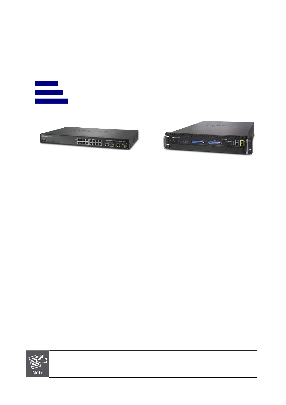
24-Port VDSL2 + 2G TP/SFP Combo
Managed Switch
VC-820M
8-Port VDSL2 + 2G TP/SFP Combo
Managed Switch
Page 2

User’s Manual of VC-820M / VC-2400MR Series
Trademarks
Copyright © PLANET Technology Corp. 2010.
Contents subject to which revision without prior notice.
PLANET is a registered trademark of PLANET Technology Corp. All other trademarks belong to their respective owners.
Disclaimer
PLANET Technology does not warrant that the hardware will work properly in all environments and applications, and makes
no warranty and representation, either implied or expressed, with respect to the quality, performance, merchantability, or
fitness for a particular purpose.
PLANET has made every effort to ensure that this User's Manual is accurate; PLANET disclaims liability for any
inaccuracies or omissions that may have occurred.
Information in this User's Manual is subject to change without notice and does not represent a commitment on the part of
PLANET. PLANET assumes no responsibility for any inaccuracies that may be contained in this User's Manual. PLANET
makes no commitment to update or keep current the information in this User's Manual, and reserves the right to make
improvements to this User's Manual and/or to the products described in this User's Manual, at any time without notice.
If you find information in this manual that is incorrect, misleading, or incomplete, we would appreciate your comments and
suggestions.
FCC Warning
This equipment has been tested and found to comply with the limits for a Class A digital device, pursuant to Part 15 of the
FCC Rules. These limits are designed to provide reasonable protection against harmful interference when the equipment is
operated in a commercial environment. This equipment generates, uses, and can radiate radio frequency energy and, if not
installed and used in accordance with the Instruction manual, may cause harmful interference to radio communications.
Operation of this equipment in a residential area is likely to cause harmful interference in which case the user will be
required to correct the interference at whose own expense.
CE Mark Warning
This is a Class A product. In a domestic environment, this product may cause radio interference, in which case the user
may be required to take adequate measures.
Energy Saving Note of the Device
This power required device does not support Standby mode operation.
For energy saving, please remove the power cable to disconnect the device from the power circuit.
Without removing power cable, the device will still consuming power from the power source. In the view of Saving the
Energy and reduce the unnecessary power consuming, it is strongly suggested to remove the power connection for the
device if this device is not intended to be active.
WEEE Warning
To avoid the potential effects on the environment and human health as a result of the presence of
hazardous substances in electrical and electronic equipment, end users of electrical and electronic
equipment should understand the meaning of the crossed-out wheeled bin symbol. Do not dispose of
WEEE as unsorted municipal waste and have to collect such WEEE separately.
Revision
PLANET 8/24-Port VDSL2 + 2 Gigabit TP/SFP Managed Switch User’s manual
FOR MODELS: VC-2400MR / VC-2400MR48 / VC-820M
REVISION: 1.5 (JUNE.2010)
Part No.: 2080-AC0160-001
2
Page 3

User’s Manual of VC-820M / VC-2400MR Series
TABLE OF CONTENTS
1. INTRODUCTION ..........................................................................................................8
1.1 Package Contents................................................................................................................................8
1.2 Product Description.............................................................................................................................9
1.3 How to Use This Manual................................................................................................................... 11
1.4 Product Features............................................................................................................................... 12
1.5 Product Specification....................................................................................................................... 14
2. INSTALLATION..........................................................................................................17
2.1 Hardware Description....................................................................................................................... 17
2.1.1 Switch Front Panel .................................................................................................................... 17
2.1.2 LED Indications.......................................................................................................................... 19
2.1.3 Switch Rear Panel ..................................................................................................................... 22
2.2 Install the Switch............................................................................................................................... 24
2.2.1 Desktop Installation ................................................................................................................... 24
2.2.2 Rack Mounting........................................................................................................................... 25
2.2.3 Installing the SFP transceiver.................................................................................................... 27
2.3 Wiring for VDSL2 Ports .................................................................................................................... 29
3. SWITCH MANAGEMENT...........................................................................................32
3.1 Requirements.................................................................................................................................... 32
3.2 Management Access Overview ....................................................................................................... 33
3.3 Web Management.............................................................................................................................. 34
3.4 SNMP-Based Network Management ............................................................................................... 35
3.5 Administration Console.................................................................................................................... 35
3.6 Protocols............................................................................................................................................ 37
3.6.1 Virtual Terminal Protocols ......................................................................................................... 37
3.6.2 SNMP Protocol .......................................................................................................................... 37
3.6.3 Management Architecture ......................................................................................................... 37
4. WEB-BASED MANAGEMENT...................................................................................38
4.1 About Web-based Management ...................................................................................................... 38
4.1.1 Requirements ............................................................................................................................ 39
4.1.2 Logging on the switch................................................................................................................ 39
4.1.3 Main WEB PAGE....................................................................................................................... 41
4.2 System................................................................................................................................................ 42
4.2.1 System Information.................................................................................................................... 43
3
Page 4

User’s Manual of VC-820M / VC-2400MR Series
4.2.2 IP Configuration......................................................................................................................... 47
4.2.3 Console Information .................................................................................................................. 49
4.2.4 SNMP Configuration.................................................................................................................. 49
4.2.5 Syslog Setting............................................................................................................................ 57
4.2.6 SNTP Setting............................................................................................................................. 58
4.2.7 Firmware Upgrade..................................................................................................................... 59
4.2.8 Configuration Backup ................................................................................................................ 61
4.2.9 Factory Default .......................................................................................................................... 64
4.2.10 System Reboot ........................................................................................................................ 64
4.3 Port Configuration ............................................................................................................................ 65
4.3.1 Port Control................................................................................................................................65
4.3.2 Port Status ................................................................................................................................. 67
4.3.3 Port Statistics............................................................................................................................. 67
4.3.4 Port Sniffer................................................................................................................................. 68
4.3.5 Protect Port................................................................................................................................70
4.4 VLAN configuration .......................................................................................................................... 71
4.4.1 VLAN Overview ......................................................................................................................... 71
4.4.2 Static VLAN Configuration......................................................................................................... 74
4.4.3 Port-based VLAN....................................................................................................................... 75
4.4.4 802.1Q VLAN............................................................................................................................. 77
4.4.5 Q-in-Q VLAN.............................................................................................................................. 82
4.4.6 GVRP VLAN .............................................................................................................................. 86
4.5 Trunking............................................................................................................................................. 89
4.5.1 Aggregator setting ..................................................................................................................... 89
4.5.2 Aggregator Information.............................................................................................................. 90
4.5.3 State Activity.............................................................................................................................. 94
4.6 Forwarding and Filtering.................................................................................................................. 95
4.6.1 Dynamic MAC Table.................................................................................................................. 95
4.6.2 Static MAC Table....................................................................................................................... 96
4.6.3 MAC Filtering............................................................................................................................. 97
4.7 IGMP Snooping ................................................................................................................................. 98
4.7.1 Theory........................................................................................................................................ 98
4.7.2 IGMP Configuration ................................................................................................................. 102
4.8 Spanning Tree Protocol.................................................................................................................. 103
4.8.1 Theory...................................................................................................................................... 103
4.8.2 Illustration of STP .................................................................................................................... 106
4
Page 5

User’s Manual of VC-820M / VC-2400MR Series
4.8.3 STP Parameters ...................................................................................................................... 107
4.8.4 STP System Configuration ...................................................................................................... 109
4.8.5 Port Configuration.................................................................................................................... 112
4.9 DHCP Relay & Option 82................................................................................................................ 114
4.10 LLDP............................................................................................................................................... 116
4.10.1 LLDP Configuration ............................................................................................................... 116
4.10.2 PerPort Configuration ............................................................................................................ 117
4.11 Access Control List ...................................................................................................................... 118
4.12 Security Manager.......................................................................................................................... 122
4.13 MAC Limit ...................................................................................................................................... 122
4.13.1 MAC Limit Configuration........................................................................................................ 122
4.13.2 MAC Limit Port Status ........................................................................................................... 124
4.14 802.1x Configuration..................................................................................................................... 125
4.14.1 Understanding IEEE 802.1x Port-Based Authentication ....................................................... 125
4.14.2 System Configuration ............................................................................................................ 128
4.14.3 802.1x Port Configuration...................................................................................................... 130
4.14.4 Misc Configuration................................................................................................................. 131
4.15 QoS Configuration........................................................................................................................ 132
4.15.1 Understand QoS.................................................................................................................... 132
4.15.2 QoS Configuration ................................................................................................................. 133
4.15.3 TOS/DSCP ............................................................................................................................ 136
4.16 VDSL Configuration...................................................................................................................... 139
4.16.1 Profile Configuration .............................................................................................................. 139
4.16.2 VDSL Port Status .................................................................................................................. 142
5. CONSOLE MANAGEMENT.....................................................................................147
5.1 Login in the Console Interface ...................................................................................................... 147
5.2 Configure IP address...................................................................................................................... 148
5.3 Commands Level ............................................................................................................................ 150
6. COMMAND LINE INTERFACE ................................................................................151
6.1 Operation Notice............................................................................................................................. 151
6.2 System Commands......................................................................................................................... 152
6.3 Switch Static Configuration........................................................................................................... 154
6.3.1 Port Configuration and show status ........................................................................................ 154
6.4 Trunk Configuration........................................................................................................................ 158
6.4.1 Trunking Commands ............................................................................................................... 158
6.4.2 LACP Command...................................................................................................................... 159
5
Page 6

User’s Manual of VC-820M / VC-2400MR Series
6.5 VLAN Configuration........................................................................................................................ 161
6.5.1 Virtual LANs............................................................................................................................. 161
6.5.2 VLAN Mode: Port-based.......................................................................................................... 162
6.5.3 Advanced 802.1Q VLAN Configuration................................................................................... 163
6.6 Misc Configuration.......................................................................................................................... 166
6.7 Administration Configuration........................................................................................................ 167
6.7.1 Change Username / Password................................................................................................ 167
6.7.2 IP Configuration....................................................................................................................... 168
6.7.3 Reboot switch .......................................................................................................................... 169
6.7.4 Reset to Default....................................................................................................................... 169
6.7.5 TFTP Update Firmware ........................................................................................................... 169
6.7.6 Restore Configure File............................................................................................................. 169
6.7.7 Backup Configure File ............................................................................................................. 170
6.8 MAC limit.......................................................................................................................................... 170
6.9 Port Mirroring Configuration.......................................................................................................... 171
6.10 Quality of Service.......................................................................................................................... 172
6.10.1 QoS Configuration ................................................................................................................. 172
6.10.2 Per Port Priority ..................................................................................................................... 173
6.11 MAC Address Configuration........................................................................................................ 174
6.12 STP/MSTP Commands.................................................................................................................. 176
6.13 SNMP.............................................................................................................................................. 183
6.13.1 System Options ..................................................................................................................... 183
6.13.2 Community Strings ................................................................................................................ 184
6.13.3 Trap Managers ...................................................................................................................... 184
6.14 IGMP............................................................................................................................................... 185
6.15 802.1x Protocol.............................................................................................................................. 187
6.16 Access Control List ...................................................................................................................... 190
6.16.1 IPv4 ACL commands............................................................................................................. 190
6.16.2 Non-IPv4 ACL commands..................................................................................................... 192
6.17 Binding........................................................................................................................................... 193
6.17.1 SIP/SMAC binding commands .............................................................................................. 193
6.18 DHCP Configuration ..................................................................................................................... 195
6.19 VDSL2 Commands........................................................................................................................ 196
6.19.1 VDSL2 interface Commands................................................................................................. 196
6.19.2 VDSL2 profile Commands..................................................................................................... 199
7. SWITCH OPERATION..............................................................................................208
6
Page 7

User’s Manual of VC-820M / VC-2400MR Series
7.1 Address Table ................................................................................................................................. 208
7.2 Learning........................................................................................................................................... 208
7.3 Forwarding & Filtering.................................................................................................................... 208
7.4 Store-and-Forward.......................................................................................................................... 208
7.5 Auto-Negotiation............................................................................................................................. 208
8. TROUBLE SHOOTING.............................................................................................210
APPENDIX A—RJ-45 PIN ASSIGNMENT...................................................................212
A.1 Switch's RJ-45 Pin Assignments.................................................................................................. 212
A.2 10/100Mbps, 10/100Base-TX.......................................................................................................... 212
A.3 RJ-21 Connector pin out for VC-2400MR Series......................................................................... 214
A.4 RJ-21 / Telco 50 Cable pin out ...................................................................................................... 215
7
Page 8
User’s Manual of VC-820M / VC-2400MR Series
1. Introduction
The PLANET Layer 2 Managed Switch series - VC-2400MR, VC-2400MR48, VC-820M are multiple VDSL2 ports Ethernet
Switched with Gigabit TP/SFP fiber optical combo connective ability and robust layer 2 features; the description of these
models as below:
VC-820M :
VC-2400MR :
VC-2400MR48 :
Terms of “Managed Switch” means the Switches mentioned titled in the cover page of this User’s manual, i.e.VC-820M,
VC-2400M Rand VC-2400MR48.
8-Port VDSL2 + 2-Port Gigabit TP/SFP Combo Managed Switch
24-Port VDSL2 + 2-Port Gigabit TP/SFP Combo Managed Switch / AC Power
24-Port VDSL2 + 2-Port Gigabit TP/SFP Combo Managed Switch / DC Power
VC-820M VC-2400MR / VC-2400MR48
1.1 Package Contents
Open the box of the Managed Switch and carefully unpack it. The box should contain the following items:
Check the contents of your package for following parts:
; The Managed Switch
; User’s Manual CD
; Quick Installation Guide
; 19” Rack mount Accessory Kit
; Power Cord
; Rubber Feet
; RS-232 DB9 female Console Cable
; 2 meter Telco-50 Cable (VC-2400MR Series
Only)
If any of these are missing or damaged, please contact your dealer immediately, if possible, retain the carton including the
original packing material, and use them against to repack the product in case there is a need to return it to us for repair.
VC-2400MR or VC-2400MR48 comes with one power system by default. The power slot 2 is vacant slot and
x1
x1
x1
x1
x1
x4
x1
x1
can be installed with VC-RPS200 or VC-RPS48, please consult your local dealer for the order information.
8
Page 9

User’s Manual of VC-820M / VC-2400MR Series
1.2 Product Description
Over view
High Performance VDSL2 Data Rate over Existing Phone Lines
PLANET VC-2400MR Series and VC-820M are multiple ports VDSL2 Managed CO Switch (Central Office) for Telecom,
ISP (Internet Service Provider), SI (System Integration), IP Surveillance provider and etc. It is based on two core networking
technology, Ethernet and VDSL2 (Very-high-data-rate Digital Subscriber Line 2). Co-works with PLANET developed CPE
(Customer Premises Equipment) – the VC-23x series CPE, they offers the absolutely fastest data transmission speeds over
existing copper telephone lines without the need of rewiring. The ideal xDSL technology provides the best solution in the
last mile.
Delivers High-Demand Services Connectivity for ISP / Triple Play Devices
As the demand for home broadband connections steadily increases, cable modems and ADSL now are not fast enough to
support the integration of home services. VDSL2 are viewed as the next step media in providing a complete
home-communication / entertainment solution. The EoVDSL(Ethernet over VDSL) provides up to 100Mbps download
capability of VDSL2 Managed Switch enables many Multi-Media services to come true on local Internet,
¾ IPTV / HDTV
¾ VOD (Video on Demand)
¾ Voice over IP
¾ Video Conference / Video Phone
¾ On-Line Game
¾ Internet Radio / On-Line Music
¾ Long distance education
The VDSL2 switch provides the excellent bandwidth to satisfy the triple play devices for home entertainment and
communication.
Implements with Existing Telephone Copper Wires
Each VDSL2 port of the VDSL2 Switch provides two copper phone wire interfaces–one for VDSL2 connection and the other
one for POTS (Plain Old Telephone Service) connection. To share the existing phone line with POTS, the VDSL2 Switch
has built-in POTS splitter that helps the voice of telephone and data of network applications transmitting at the same wire
without interrupted.
Traffic Flow QoS for application services ensured
The VDSL2 Switch contains robust QoS features such as Port-Based, 802.1p priority and also IP TOS/DSCP, it guarantees
the best performance at VoIP and Video stream transmission and empowers the enterprises to take full advantages of the
limited network resources.
9
Page 10
User’s Manual of VC-820M / VC-2400MR Series
Selectable VDSL2 data rate for Service Differentiation
Through the management interface, administrator can control the data transmit speed of each VDSL2 interface. Telecom
and ISP can immediately and remotely upgrade/downgrade bandwidth service by different demand.
Efficient Management
Afford the current network to grow and expand, the PLANET VC-2400MR series and VC-820M provide console and telnet
command line interface, advanced WEB and SNMP management interface to fill this kind of demand. With its built-in
Web-based management, the VDSL2 Switch offers an easy-to-use, platform-independent management and configuration
facility. The VDSL2 Switch supports standard Simple Network Management Protocol (SNMP) and can be monitored via any
standard-based management software. For text-based management, the VDSL2 Switch can also be accessed via Telnet
and the console port. Moreover, the VDSL2 Switch offers secure remote management by supporting Secure Socket Layer
(SSL) connection which encrypts the packet content at each session. These features provide a good cost-effective way to
manage the devices from the internet environment without to add extra Secure system of Hardware or Software.
Robust Layer 2 Features
For efficient management, via WEB interface the VC-2400MR Series can be programmed for basic switch management
functions such as port speed configuration, Port link aggregation, IEEE 802.1Q VLAN and Q-in-Q VLAN, Port Mirroring,
Rapid Spanning Tree and ACL security. Additionally, the firmware includes advanced features such as IGMP snooping,
QoS (Quality of Service), broadcast storm and bandwidth control, to enhance bandwidth utilization.
Advanced Security
The VDSL2 Switch offers comprehensive Layer 2, Layer 3 and Layer 4 Access Control List (ACL) to filter out unwanted
traffic. Its protection mechanisms comprises of RADIUS and Port-based 802.1x user and device authentication. Moreover,
the VDSL2 Switch provides MAC filter, Static MAC, IP/MAC binding and Port Security for enforcing security policies to the
edge. The administrators can now construct highly secured corporate networks with considerably less time and effort than
before.
Extremely Reliable Design to ensure continuous operation (VC-2400 MR Series)
Power Redundant – The VC-2400MR series supports the optional hot-swappable Redundant Power System (RPS) to
ensure continuous operation. The VC-2400MR equips with one 100~240V AC power supply unit andVC-2400MR48 equips
with one DC -48V power supply unit on their standard package. To enhance the reliability, both VC-2400MR and
VC-2400MR48 provide one spare power supply unit slot for optional 100~240V AC or DC -48V redundant power supply
installation. The continuous power systems are specifically designed to handle the demands of high tech facilities requiring
the highest power integrity available. Also, -48V DC power supply implemented makes the VC-2400MR series VDSL2
Switch as telecom level device that can be located at the electronic room.
VC-2400MR – One 100~240V AC VC-2400MR48 – One -48VDC
10
Page 11

User’s Manual of VC-820M / VC-2400MR Series
Temperature and FAN Status Monitoring - The Managed VDSL2 Switch is equipped with temperature senor and cooling
fans to ensure reliable operation. Whenever the abnormal temperature is detected or cooling fan stops service, the
Managed Media Converter Chassis would display related information on the Web management interface. Therefore, it
helps the administrator to efficiently manage the media conversion operation.
1.3 How to Use This Manual
This User Manual is structured as follows:
Section 2, INSTALLATION
The section explains the functions of the Switch and how to physically install the Managed Switch.
Section 3, SWITCH MANAGEMENT
The section contains the information about the software function of the Managed Switch.
Section 4, WEB CONFIGURATION
The section explains how to manage the Managed Switch by Web interface.
Section 5, CONSOLE MANAGEMENT
The section describes how to use the Console management interface.
Section 6, COMMAND LINE INTERFACE
The section explains how to manage the Managed Switch by Command Line interface.
Section 7, SWITCH OPERATION
The chapter explains how to does the switch operation of the Managed Switch.
Section 8, TROUBSHOOTING
The chapter explains how to trouble shooting of the Managed Switch.
Appendix A
The section contains cable information of the Managed Switch.
11
Page 12

User’s Manual of VC-820M / VC-2400MR Series
1.4 Product Features
¾ VDSL Interface
VC-2400MR / VC-2400MR48
24 Full-Duplex VDSL links via RJ-21(Telco-50) connector
24 corresponding POTS lines via RJ-21(Telco-50) connector
Built-in POTS splitter for each VDSL port
Auto-speed function for VDSL2 link (by distance and cable quality)
VC-820M
8 x RJ-11 connectors for VDSL2 connection
8 x RJ-11 connectors for telephone/POTS connection
Built-in POTS splitter for each VDSL port
Auto-speed function for VDSL2 link (by distance and cable quality)
¾ Ethernet Interface
2 10/100/1000Mbps TP and SFP shared combo interfaces
Auto-MDI/MDI-X detection on Gigabit RJ-45 port
¾ VDSL2 Features
Cost-effective VDSL2 link and central management solution
ITU-T G.993.2 VDSL2 standard
DMT (Discrete Multi-Tone) line coding VDSL
Selectable bandwidth control and target SNR margin
Built-in surge protection to against surge damage from high energy spike
Voice and data communication can be shared on the existing telephone wire simultaneously
¾ Layer 2 Features
Prevents packet loss Flow Control:
• IEEE 802.3x PAUSE frame Flow Control for Full-Duplex mode
• Back-Pressure Flow Control in Half-Duplex mode
High performance Store and Forward architecture, broadcast storm control, runt/CRC filtering eliminates
erroneous packets to optimize the network bandwidth
8K MAC Address Table, automatic source address learning and ageing
Support VLAN:
• IEEE 802.1Q Tag-Based VLAN
• Port-Based VLAN
• Q-in-Q tunneling (Double Tag VLAN)
• GVRP for dynamic VLAN Management
• Private VLAN Edge (PVE / Protected Port )
Supports Link Aggregation
• Up to 13 Trunk groups
• Up to 8 ports per trunk group with 1.6Gbps bandwidth (Full Duplex mode)
• IEEE 802.3ad LACP (Link Aggregation Control Protocol)
• Cisco ether-Channel (Static Trunk)
Support Spanning Tree Protocol:
12
Page 13

• STP, IEEE 802.1D (Classic Spanning Tree Protocol)
• MSTP, IEEE 802.1s (Multiple Spanning Tree Protocol, spanning tree by VLAN)
¾ Quality of Service
4 priority queues on all switch ports
Traffic classification:
• IEEE 802.1p Class of Service
• IP TOS / DSCP code priority
• Port Base priority
Strict priority and weighted round robin (WRR) CoS policies
Ingress/Egress Bandwidth control on each port
¾ Multicast
IGMP Snooping v1 and v2
IGMP Snooping v2 fast leave
IGMP Query mode for Multicast Media application
¾ Security
User’s Manual of VC-820M / VC-2400MR Series
IEEE 802.1x Port-Based network access control protocol
RADIUS users access authentication
L3 / L4 Access Control List (ACL)
Source IP-MAC / Port-Binding
Port Security for Source MAC address entries filtering
¾ Management
Switch Management Interface
- Telnet Command Line Interface
- Web switch management
- SNMP v1, v2c, v3 switch management
- SSL switch management
DHCP client for IP address assignment
DHCP Option82 and DHCP Relay
Link Layer Discovery Protocol (LLDP) for easy network management
Built-in Trivial File Transfer Protocol (TFTP) client
Firmware upgrade via TFTP or HTTP
Configuration restore / backup via TFTP or HTTP
Event message logging to remote Syslog server
Four RMON groups 1, 2, 3, 9 (history, statistics, alarms, and events)
SNMP trap for interface Link Up and Link Down notification
Supports Ping function
Reset button for system reboot or reset to factory default
1 RS-232 male DB9 console interface for Switch basic management and setup
13
Page 14
User’s Manual of VC-820M / VC-2400MR Series
1.5 Product Specification
Product VC-820M VC-2400MR VC-2400MR48
Hardware Specification
8-Port VDSL2
VDSL2 Interface
1000Mbps Copper Ports 2 10/100/1000Mbps RJ-45 Auto-MDI/MDI-X ports
SFP/mini-GBIC Slots
Surge protect
Console
Switch Architecture
Switch Fabric
Switch Throughput 4.16Mpps @64Bytes 6.547Mpps @64Bytes
Address Table
Share Data Buffer
Maximum Frame Size
Flow Control
RJ-11 connectors
8-Port POTS/Telephone
RJ-11 connectors
2 1000Base-SX/LX/BX,
shared with Port-9~Port-10
3KV 3KV
1 x RS-232 Serial Port (DB9, 57600, 8, N, 1)
Store-and-Forward
5.6Gbps / non-blocking 8.8Gbps / non-blocking
8K entries
256K Bytes 512K Bytes
9K Bytes packet
Back pressure for Half Duplex
IEEE 802.3x Pause Frame for Full Duplex
24-Port VDSL2
RJ-21(Telco-50) connectors
24-Port POTS/Telephone
RJ-21(Telco-50) connectors
2 1000Base-SX/LX/BX, shared with Port-25~Port-26
LED
Reset Button
Dimension (W x D x H)
Weight
Power Requirement
Power Consumption
System: Power Status
Alert: FAN 1, FAN2, FAN3
alert
VDSL: VDSL Link/Sync.
Gigabit Port: 1000
Link/Active, 100 Link/Active
< 5 sec: System reboot
> 5 sec: Factory Default
440 x 220 x 44mm
1U height
2.9kg
100~240V AC, 50/60Hz 100~240V AC, 50/60Hz 48V DC (Range: 30V~60V)
System ON:
26.7 Watts max.
Full Load:
57.2 Watts max.
。 VDSL: twisted-pair telephone wires (AWG24 or better) up to 1.4km
System: Power, Status
Alert: FAN 1, FAN 2, Power 1, Power 2
VDSL: VDSL Link/Sync.
Gigabit Port: 1000 Link/Active, 100 Link/Active
440 x 351 x 88mm
2U height
6.4kg - with one AC Power
module
System ON:
73.5 Watts max.
Full Load:
117 Watts max.
6.4kg - with one AC Power
module
Cables
。 10Base-T: 2-Pair UTP Cat.3,4,5 up to 100m (328ft)
。 100Base-TX: 2-Pair UTP Cat.5, up to 100m (328ft)
14
Page 15
VDSL2
User’s Manual of VC-820M / VC-2400MR Series
。 1000Base-T: 4-pair UTP Cat 5E, up to 100m
。 1000Base-SX: 50/125μm and 62.5/125μm fiber-optic cable, up to 550m
。 1000Base-LX: 9/125μm fiber optic cable, from 10km to 120km
VDSL2 Standard
Band Plan
Profile
Encoding
Performance / Distance
(Based on AWG26 wires)
VDSL2 Features
Layer 2 Function
Management Interface Console, Telnet, Web Browser, SSL, SNMPv1/v2c/v3
Gigabit Port Configuration
Gigabit Port Status
Port Mirroring
Bandwidth Control
VLAN
Link Aggregation
QoS
Comply with ITU-T G.993.1 and G.993.2.
Supports provisioning the VDSL optional band (25K to 138K Hz) usage
Selectable band plan for each VDSL line on a per port basis
Band plan A:
- Profile 998, Annex A of G.993.1
Band plan B:
- Profile 997, Annex B of G.993.1
Selectable spectrum profile of 8a/b/c/d, 12a/b, 17a, and 30a for frequency bands (Annex
A, B and C) defined in G.993.2
VDSL-DMT
• Full VDSL2 Down Stream / Up Stream bandwidth up to:
。 <Under testing>
Selectable rate limit control
Selectable target SNR (Signal to Noise Ratio) mode
POTS voices pass through
Port disable/enable
Auto-negotiation
10/100/1000Mbps full and half duplex mode selection
Flow Control disable / enable
Display each port’s speed duplex mode, link status and Flow control status.
Auto negotiation status, trunk status.
TX / RX / Both
1 to 1 monitor
Ingress / Egress rate limit control
Gigabit Port:
• Allow to configure per 128Kbps
VDSL2 Port:
• Allow to configure per 5Mbps
IEEE 802.1Q Tag-based VLAN, up to 255 VLANs groups, out of 4041 VLAN IDs
Port-based VLAN
GVRP
Q-in-Q tunneling
Private VLAN Edge(PVE / Protected port) with two protected port groups
Static Port Trunk
IEEE 802.3ad LACP (Link Aggregation Control Protocol)
Supports 13 groups of 8-Port trunk support
4 priority queue
Traffic classification based on:
- Port priority
- 802.1p priority
- DSCP/TOS field in IP Packet
15
Page 16

User’s Manual of VC-820M / VC-2400MR Series
IGMP Snooping IGMP (v1/v2) Snooping, up to 256 multicast Groups
Access Control List
SNMP MIBs
Standards Conformance
IP-Based Layer 3 / Layer 4 ACL
Up to 220 ACL rule entries
RFC-1213 MIB-II
RFC-2863 Interface MIB
RFC-2665 EtherLike MIB
RFC-1493 Bridge MIB
RFC-2819 RMON MIB (Group 1, 2, 3 and 9)
RFC-2737 Entity MIB
Regulation Compliance
Protocols and Standards
Compliance
FCC Part 15 Class A, CE
ITU-T
- G.993.1 (VDSL)
- G.997.1
- G.993.2 VDSL2
IEEE 802.3 10BASE-T
IEEE 802.3u 100BASE-TX
IEEE 802.3z Gigabit SX/LX
IEEE 802.3ab 1000BASE-T
IEEE 802.3x Flow Control
IEEE 802.1p Class of service
IEEE 802.1Q VLAN Tagging
IEEE 802.3ad Link Aggregation Control Protocol (LACP)
IEEE 802.1d Spanning Tree Protocol
IEEE 802.1s Multiple Spanning Tree
RFC 768 UDP
RFC 793 TFTP
RFC 791 IP
RFC 792 ICMP
RFC 2068 HTTP
RFC 1112 IGMP version 1
RFC 2236 IGMP version 2
16
Page 17
User’s Manual of VC-820M / VC-2400MR Series
2. INSTALLATION
This section describes the hardware features and installation of the Managed Switch on the desktop or rack mount. For
easier management and control of the Managed Switch, familiarize yourself with its display indicators, and ports. Front
panel illustrations in this chapter display the unit LED indicators. Before connecting any network device to the Managed
Switch, please read this chapter completely.
2.1 Hardware Description
2.1.1 Switch Front Panel
The unit front panel provides a simple interface monitoring the switch. Figure 2-1-1 to 2-1-2 shows the front panel of the
Managed Switches.
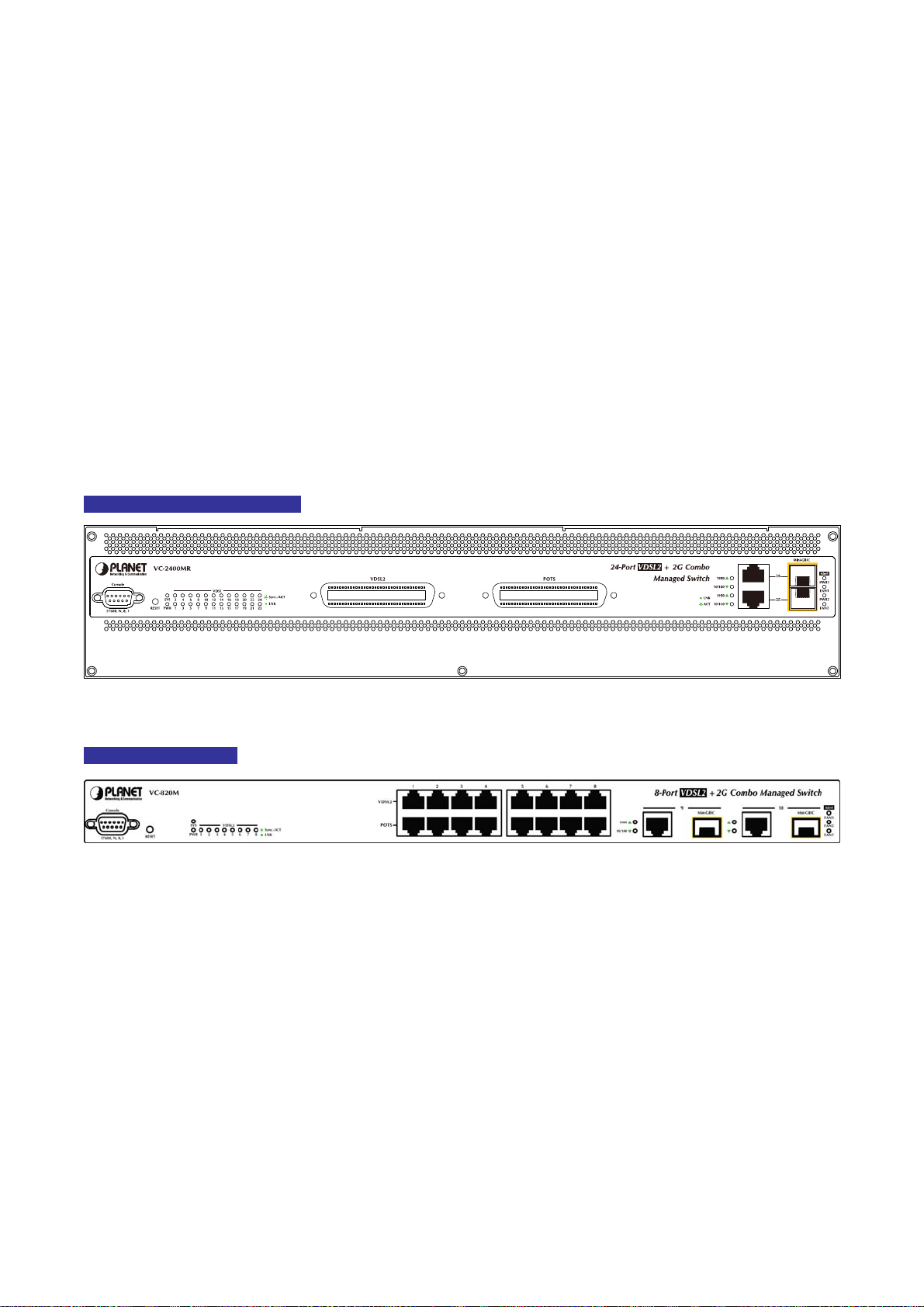
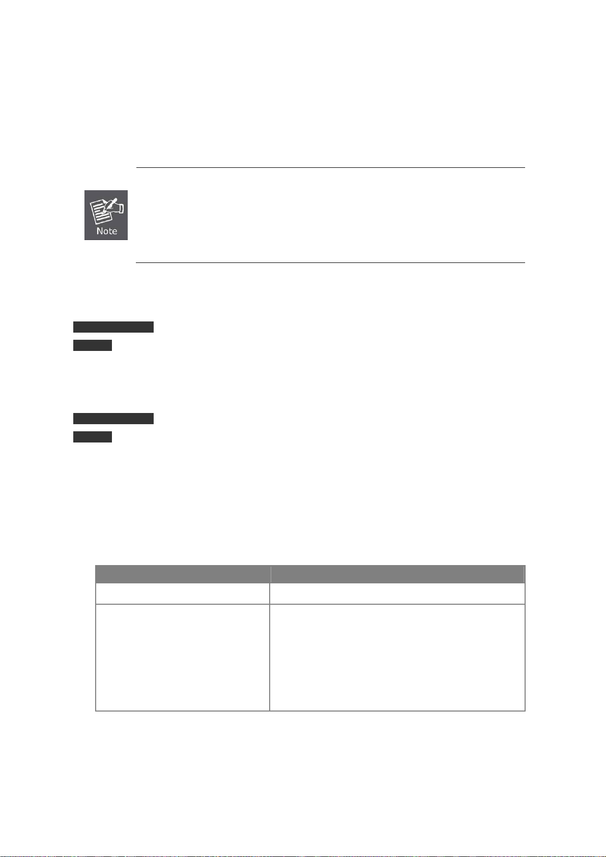
VC-2400MR Series Front Panel
Figure 2-1-1: VC-2400MR Series front panel
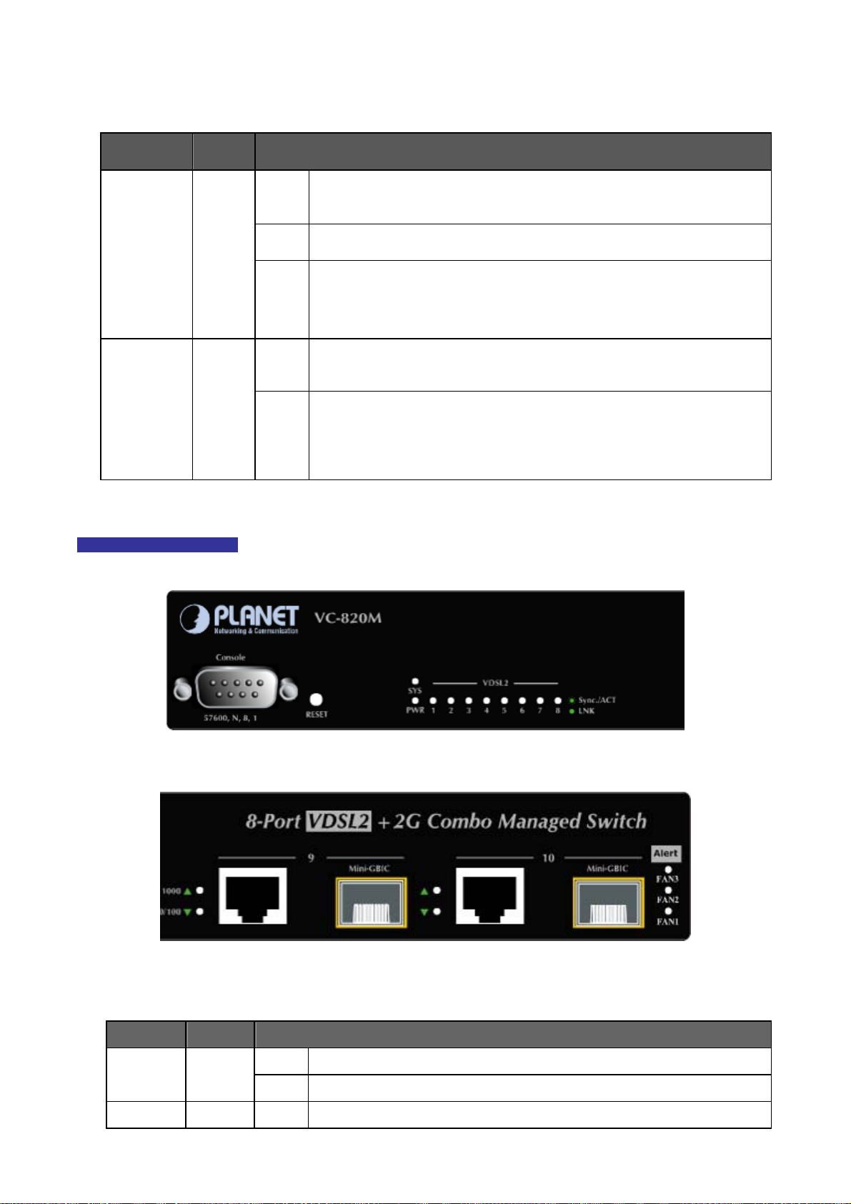
VC-820M Front Panel
Figure 2-1-2: VC-820M Switch front panel
■ Console Port
The console port is a DB9, RS-232 male serial port connector. It is an interface for connecting a terminal directly.
Through the console port, it provides rich diagnostic information includes IP Address setting, factory reset, port
management, link status and system setting. Users can use the attached RS-232 cable in the package and connect to
the console port on the device. After the connection, users an run any terminal emulation program (Hyper Terminal,
ProComm Plus, Telix, Winterm and so on) to enter the startup screen of the device.
■ VDSL2 and POTS interface
There are 24 VDSL2 ports and 24 POTS ports with 2 Telco-50 / RJ-21 type connectors on the front panel of
VC-2400MR series and there are 8 VDSL2 ports and 8 POTS ports with RJ-11 phone connectors on the front panel of
VC-820M. Each port is built-in POTS splitter that helps the voice of telephone and data of network applications
transmitting at the same wire without interrupted.
17
Page 18
User’s Manual of VC-820M / VC-2400MR Series
The VDSL2 supports auto detection transmission rate that operate in different band allocation and result in different
upstream and downstream bandwidth. And Due to different telephone line quality, cross talk or extension distance may
affect actual achievable speed; you can configure individual port in built-in management interface for optimized
connectivity.
1. The payload rate is about 9% less than the line rate due to framing overhead.
2. AWG 26 (0.4mm) cable can also be used but the distance is 20% to 40% shorter than
above table.
3. Each terminated bridge tap can reduce the VDSL link distance by 90m.The quality of the
cable, the size of the cable bundles, and the cross talk within the bundle, can also affect
other overall reach.
■ Gigabit TP Interface
VC-2400MR Series: Port-25 and Port-26
VC-820M: Port-9, Port-10
10/100/1000Base-T Copper, RJ-45 Twist-Pair: Up to 100 meters.
■ Gigabit SFP Slots
VC-2400MR Series: Port-25 and Port-26
VC-820M: Port-9, Port-10
1000Base-SX/LX mini-GBIC slot, SFP (Small Form-Factor Pluggable) transceiver module: From 550 meters
(Multi-mode fiber), up to 10/30/50/70/120 kilometers (Single-mode fiber).
■ Reset button
At the left of front panel, the reset button is designed for reboot the Managed Switch without turn off and on the power.
The following is the summary table of Reset button functions:
Reset Button Pressed and Released Function
About 1~5 second Reboot the Managed Switch
Reset the Managed Switch to Factory Default configuration.
The Managed Switch will then reboot and load the default
settings as below:
Until the SYS LED lit off
。 Default Password: admin
。 Default IP address: 192.168.0.100
。 Subnet mask: 255.255.255.0
。 Default Gateway: 192.168.0.254
18
Page 19
User’s Manual of VC-820M / VC-2400MR Series
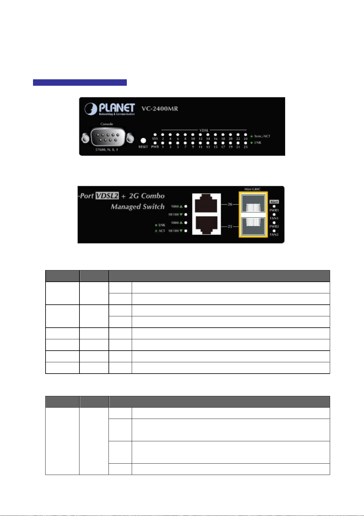
2.1.2 LED Indications
The front panel LEDs indicates instant status of port links, data activity and system power; helps monitor and troubleshoot
when needed.
VC-2400MR Series LED indication
Figure 2-1-3: VC-2400MR Series System and Port LED panel
Figure 2-1-4: VC-2400MR Series Power and fan LED panel
■ System
LED Color Function
PWR Green
SYS Orange
PWR1 Orange On:
FAN1 Orange On:
PWR2 Orange On:
FAN2 Orange On:
■ Per VDSL Interface ( Port-1 to Port-24)
LED Color Function
On: Indicate that the Switch is powered on
Off: Indicate that the Switch is powered off
Lights to indicate the system is working.
Lit:
Blink
Indicate that the system is in OS boot procedure or reset to default
Indicate that power1 is inserted and failed to work.
Indicate that fan1 is failed to work.
Indicate that power2 is inserted and failed to work.
Indicate that fan2 is failed to work.
Indicate that the VDSL link is established.
On:
VDSL
LNK/Sync
Green
Slow
Blink:
Quick
Blink:
Off:
Indicate that the VDSL is at training status with remote CPE
Indicate that the DATA link is actively sending or receiving data over that VDSL
port
Indicate that the VDSL is link down
19
Page 20
User’s Manual of VC-820M / VC-2400MR Series
■ 10/100/1000Base-T Copper / 1000Base-SX/LX SFP Interface (Port-25 and Port-26)
LED Color Function
To indicate the link through that port is successfully established with speed
On:
1000Mbps
1000
Green
LNK/ACT
10/100
Green
LNK/ACT
VC-820M LED indication
Blink:
Off:
On:
Blink:
Off:
To indicate that the switch is actively sending or receiving data over that port.
If 10/100 LNK/ACT LED is light, it indicates that the port is operating at 10Mbps
or 100Mbps
If LNK/ACT LED is Off, it indicates that the port is link down
To indicate the link through that port is successfully established with speed
10Mbps or 100Mbps
To indicate that the switch is actively sending or receiving data over that port.
If 1000 LNK/ACT LED is light, indicates that the port is operating at 1000Mbps
If 1000 LNK/ACT LED is Off, it indicates that the port is link down
Figure 2-1-5: VC-820M System and Port LED panel
Figure 2-1-6: VC-820M fan alert LED panel’
■ System
LED Color Function
PWR Green
SYS Orange On:
On: Indicate that the Switch is powered on
Off: Indicate that the Switch is powered off
Lights to indicate the system is working.
20
Page 21
User’s Manual of VC-820M / VC-2400MR Series
FAN1 Alert Orange On:
FAN2 Alert Orange On:
FAN3 Alert Orange On:
■ Per VDSL Interface ( Port-1 to Port-8)
LED Color Function
VDSL
Green
LNK/Sync
■ 10/100/1000Base-T Copper / 1000Base-SX/LX SFP Interface (Port-9 and Port-10)
LED Color Function
Blink
On:
Slow
Blink:
Quick
Blink:
Off:
Indicate that the system is in OS boot procedure or reset to default
Lights to indicate that the FAN1 failure
Lights to indicate that the FAN2 failure
Lights to indicate that the FAN3 failure
Indicate that the VDSL link is established
Indicate that the VDSL is at training status with remote CPE
Indicate that the DATA link is actively sending or receiving data over that VDSL
port
Indicate that the VDSL is link down
1000
LNK/ACT
10/100
LNK/ACT
To indicate the link through that port is successfully established with speed
On:
1000Mbps
Blink:
Green
Green
The 2 Gigabit TP/SFP combo ports are shared with Port 9/10 of VC-820M or Port25/26 of VC-2400MR
Series. Either of them can operate at the same time.
Blink:
To indicate that the switch is actively sending or receiving data over that port.
If 10/100 LNK/ACT LED is light, it indicates that the port is operating at 10Mbps
Off:
or 100Mbps
If LNK/ACT LED is Off, it indicates that the port is link down
To indicate the link through that port is successfully established with speed
On:
10Mbps or 100Mbps
To indicate that the switch is actively sending or receiving data over that port.
If 1000 LNK/ACT LED is light, it indicates that the port is operating at 1000Mbps
Off:
If 1000 LNK/ACT LED is Off, it indicates that the port is link down
21
Page 22
User’s Manual of VC-820M / VC-2400MR Series
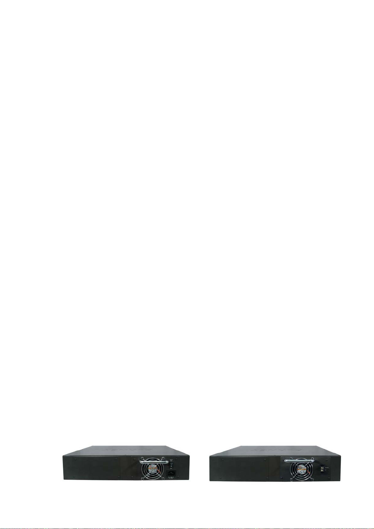
2.1.3 Switch Rear Panel
The VC-2400MR equip with one 100~240V AC power supply unit and VC-2400MR48 equip with one DC -48V power supply
unit on its standard package, both VC-2400MR and VC-2400MR48 provide one spare power supply unit slot for option
redundant power supply installation. A redundant power supply is also provided to enhance the reliability with options of
either 100~240V AC power supply unit or DC -48V power supply unit.
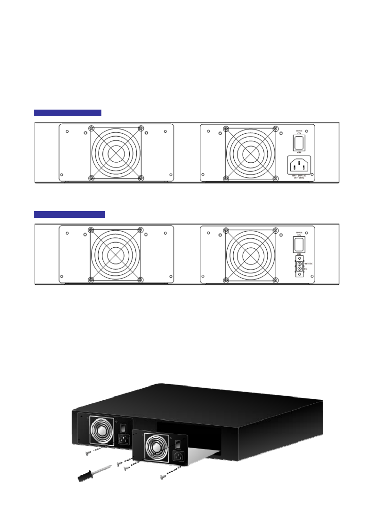
VC-2400MR Rear Panel
Figure 2-1-7: VC-2400MR rear panel with AC power module
VC-2400MR48 Rear Panel
Figure 2-1-8: VC-2400MR48 rear panel with DC power module
Install and remove the power supply unit
To install a power supply unit to VC-2400MR series, please fasten the hand screw clockwise and slide in the power supply
unit to the Managed Media Converter Chassis.
To remove a power supply unit out the VC-2400MR series, please loose the hand screw counter clockwise and pull out the
power supply unit from the VC-2400MR series.
Figure 2-1-9: Install and remove the power supply unit of VC-2400MR series
22
Page 23

User’s Manual of VC-820M / VC-2400MR Series
The rear panel of VC-8 o 240V AC, 50-60Hz. 20M indicates an AC inlet power socket, which accepts input power from 100 t
Figure 2-1-10 shows the rear panel of the Managed Switch.
VC-820M Rear Panel
Figure 2-1-10: VC-820M rear panel
1. The device is a power-required device, it means, it will not work till it is powered. If your networks
should active all the time, please consider using UPS (Uninterrupted Power Supply) for your
Power Notic
e:
device. It will prevent you from network data loss or network downtime.
2. In some area, installing a surge suppression device may also help to protect your Managed
Switch from being damaged by unregulated surge or current to the Switch or the power adap
ter.
23
Page 24
User’s Manual of VC-820M / VC-2400MR Series
2.2 Install the Switch
This section describes how to install the Managed Switch and make connections to it. Please read the following topics and
perform the procedures in the order being presented.
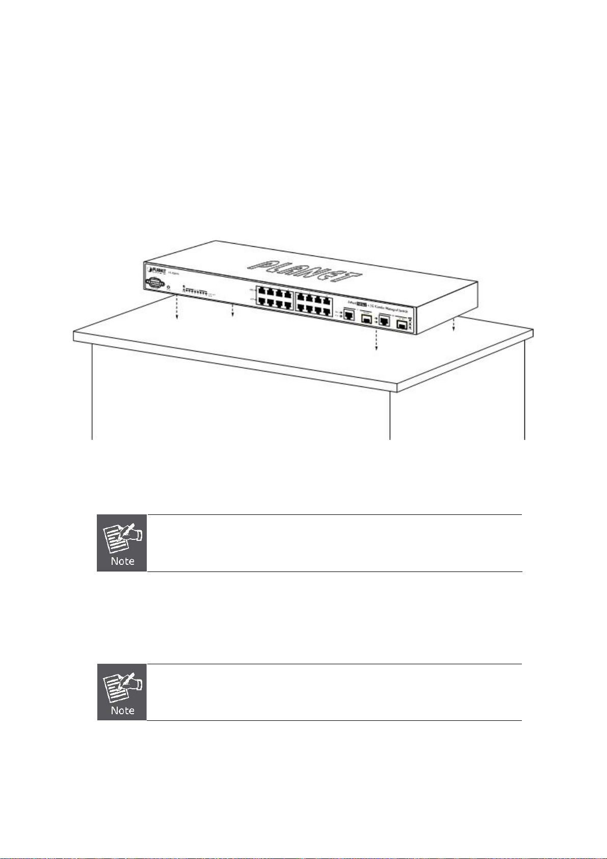
2.2.1 Desktop Installation
To install the Managed Switch on desktop or shelf, please follows these steps:
Step1: Attach the rubber feet to the recessed areas on the bottom of the Managed Switch.
Step2: Place the Managed Switch on the desktop or the shelf near an AC power source.
Figure 2-2-1: Place the Managed Switch on the desktop
Step3: Keep enough ventilation space between the Managed Switch and the surrounding objects.
When choosing a location, please keep in mind the environmental restrictions discussed in
Chapter 1, Section 4, in Specification.
Step4: Connect the Managed Switch to network devices.
A. Connect one end of a standard network cable to the 10/100/1000 RJ-45 ports on the front of the Managed Switch
B. Connect the other end of the cable to the network devices such as printer servers, workstations or routers…etc.
Connection to the Managed Switch requires UTP Category 5 network cabling with RJ-45
tips. For more information, please see the Cabling Specification in Appendix A.
Step5: Supply power to the Managed Switch.
A. Connect one end of the power cable to the Managed Switch.
B. Connect the power plug of the power cable to a standard wall outlet.
When the Managed Switch receives power, the Power LED should remain solid Green.
24
Page 25
User’s Manual of VC-820M / VC-2400MR Series
2.2.2 Rack Mounting
To install the Managed Switch in a 19-inch standard rack, please follows the instructions described below.
Step1: Place the Managed Switch on a hard flat surface, with the front panel positioned towards the front side.
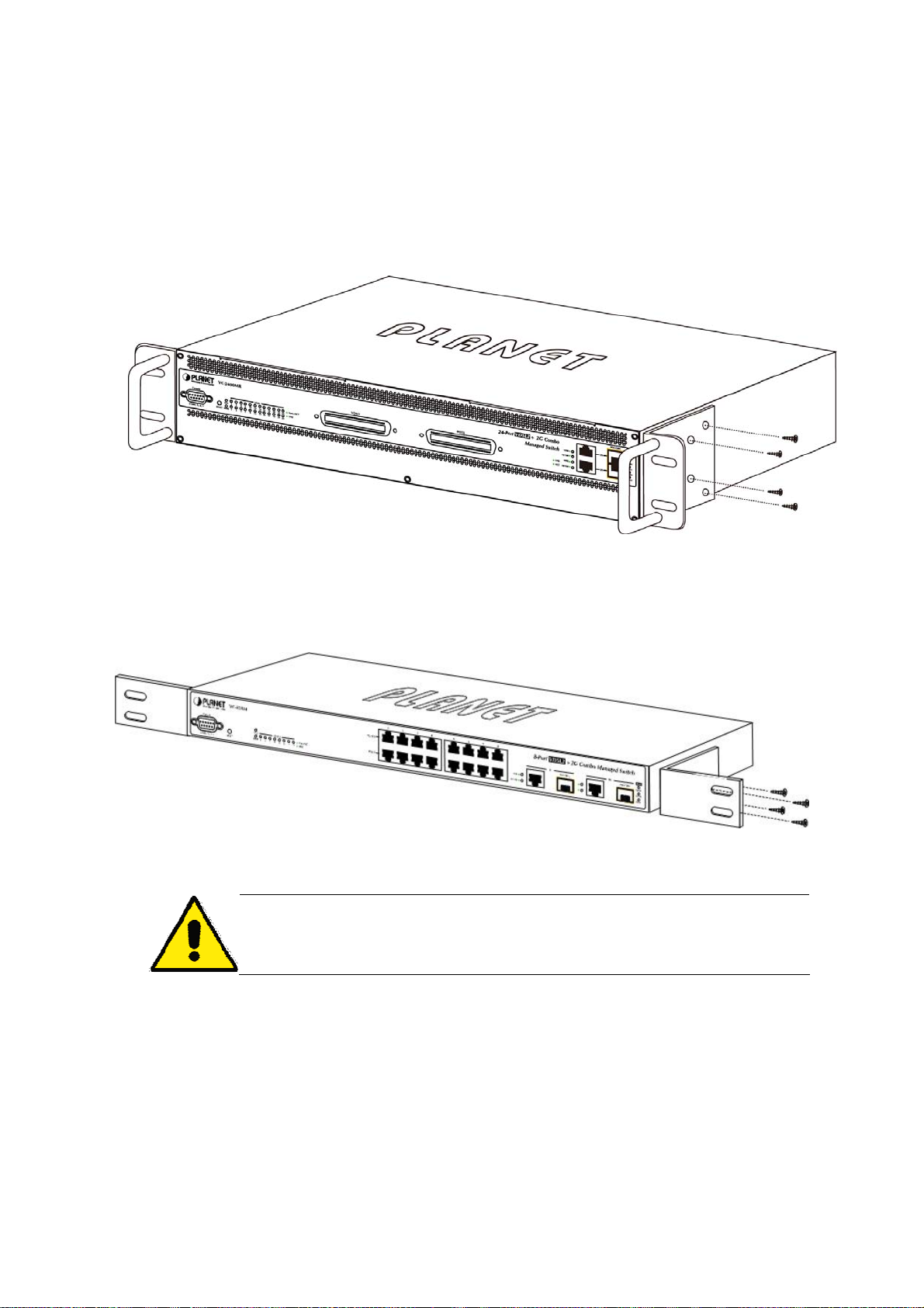
Step2: Attach the rack-mount bracket to each side of the Managed Switch with supplied screws attached to the package.
Figure 2-2-2 and Figure 2-2-3 shows how to attach brackets to one side of the Managed Switch.
Figure 2-2-1 Attach brackets to VC-2400MR series
Figure 2-2-2: Attach brackets to VC-820M
You must use the screws supplied with the mounting brackets. Damage caused to the parts
by using incorrect screws would invalidate the warranty.
Step3: Secure the brackets tightly.
Step4: Follow the same steps to attach the second bracket to the opposite side.
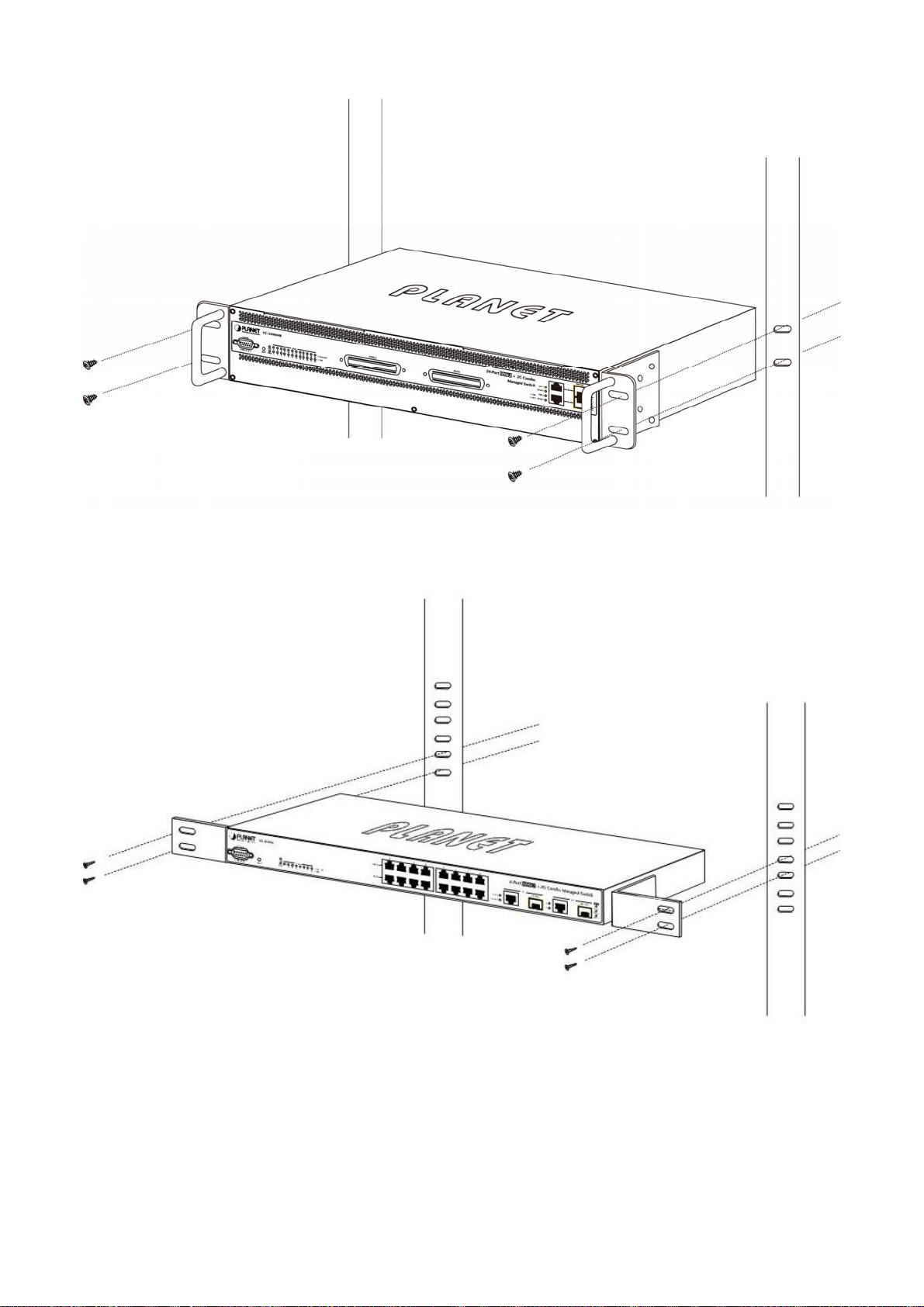
Step5: After the brackets are attached to the Managed Switch, use suitable screws to securely attach the brackets to the
rack, as shown in Figure 2-2-3 and Figure 2-2-4.
25
Page 26
User’s Manual of VC-820M / VC-2400MR Series
Figure 2-2-3: Mounting the VC-2400MR series in a Rack
Figure 2-2-4: Mounting the VC-820M in a Rack
Step6: Proceeds with the steps 4 and steps 5 of session 2.2.1 Desktop Installation to connect the network cabling and
supply power to the Managed Switch.
26
Page 27
User’s Manual of VC-820M / VC-2400MR Series
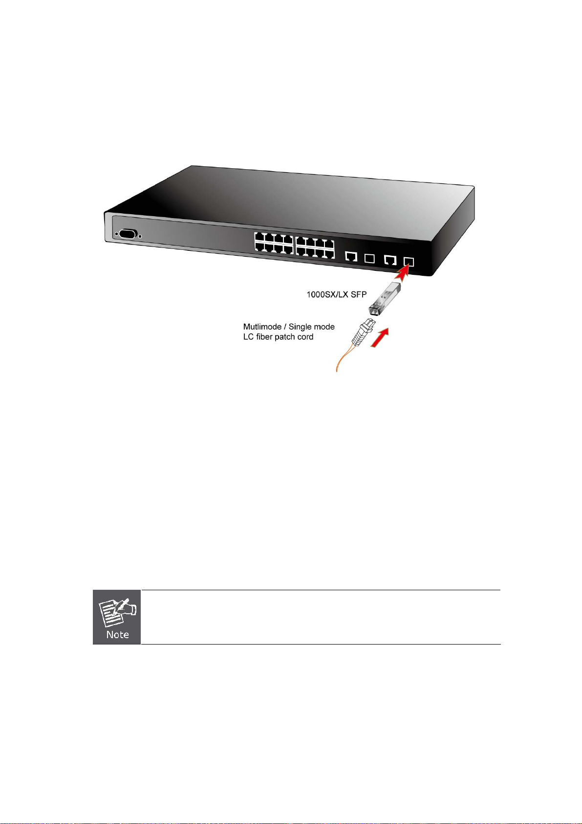
2.2.3 Installing the SFP transceiver
The sections describe how to insert an SFP transceiver into an SFP slot.
The SFP transceivers are hot-pluggable and hot-swappable. You can plug-in and out the transceiver to/from any SFP port
without having to power down the Managed Switch. As the Figure 2-2-5 appears.
Figure 2-2-5: Plug-in the SFP transceiver
Approved PLANET SFP Transceivers
PLANET Managed switches supports both single mode and multi mode SFP transceiver. The following list of approved
PLANET SFP transceivers is correct at the time of publication:
1000Base-SX/LX SFP transceiver:
MGB-SX SFP (1000BASE-SX SFP transceiver – Multi mode / 220m)
MGB-LX SFP (1000BASE-LX SFP transceiver - Single Mode / 10km)
MGB-L30 SFP (1000Base-LX SFP transceiver – Single Mode / 30Km)
MGB-L50 SFP (1000Base-LX SFP transceiver - Single Mode / 50Km)
It recommends using PLANET SFPs on the Switch. If you insert a SFP transceiver that is
not supported, the Managed Switch will not recognize it.
Before connect to the other switches, workstation or Media Converter.
1. Make sure both side of the SFP transceiver are with the same media type, for example: 1000Base-SX to
1000Base-SX, 1000Bas-LX to 1000Base-LX.
27
Page 28
User’s Manual of VC-820M / VC-2400MR Series
2. Check the fiber-optic cable type match the SFP transceiver model.
¾ To connect to 1000Base-SX SFP transceiver, use the multi-mode fiber cable- with one side must be male duplex
LC connector type.
¾ To connect to 1000Base-LX SFP transceiver, use the single-mode fiber cable-with one side must be male
duplex LC connector type.
Connect the fiber cable
1. Attach the duplex LC connector on the network cable into the SFP transceiver.
2. Connect the other end of the cable to a device – switches with SFP installed, fiber NIC on a workstation or a Media
Converter..
3. Check the LNK/ACT LED of the SFP slot on the front of the Switch. Ensure that the SFP transceiver is operating
correctly.
4. Check the Link mode of the SFP port if the link failed. Co works with some fiber-NICs or Media Converters, set the Link
mode to “1000 Force” is needed.
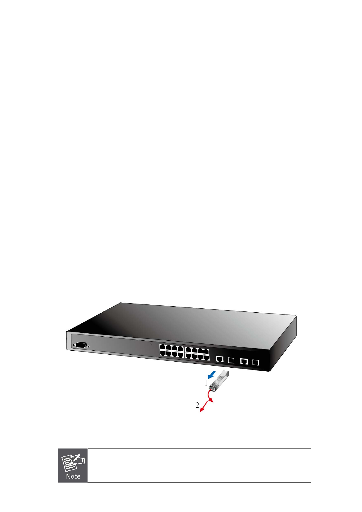
Remove the transceiver module
1. Make sure there is no network activity by consult or check with the network administrator. Or through the
management interface of the switch/converter (if available) to disable the port in advance.
2. Remove the Fiber Optic Cable gently.
3. Turn the handle of the MGB module to horizontal.
4. Pull out the module gently through the handle.
Figure 2-2-6: Pull out the SFP transceiver
Never pull out the module without pull the handle or the push bolts on the module. Direct pull
out the module with violent could damage the module and SFP module slot of the Managed
Switch.
28
Page 29
User’s Manual of VC-820M / VC-2400MR Series
2.3 Wiring for VDSL2 Ports
The VDSL2 port of VC-2400MR series uses one RJ-21 (Telco 50) connector to connect to a patch panel then link up to 24
VDSL CPEs and the VDSL2 port of VC-820M uses eight RJ-11 connectors which can be just directly connected to the
remote CPEs (VC-230, VC-230N, VC-231, VC-234 or other compatible CPE) through structured or unstructured wiring,
such as existing telephone lines. The link between the VDS2L CO Switch port and each CPE can reach speeds of up to
100/100 Mbps under 1000 feet (300 meters) with profile 30a or 18/1 Mbps over distances of up to 5000 feet (1500 meters).
You can hot swap the VDSL2 CPEs without powering down the Managed Switch or disrupting the other switch ports.
Each VC-820M and VC-2400MR series VDSL2 Managed Switch series had built-in Pain Old Telephone service (POTS)
splitter to transmit both VDSL2 traffic and telephone services, such as voice or Fax, through same phone wire. The splitter
routes VDSL2 data (high-frequency) and voice (low-frequency) traffic from the telephone line and Pri vate Branch
exchange (PBX) switch or Public Switched Telephone Network (PSTN).
The connection diagrams are as the following.
VC-2400MR Series VDSL2 and POTS connection
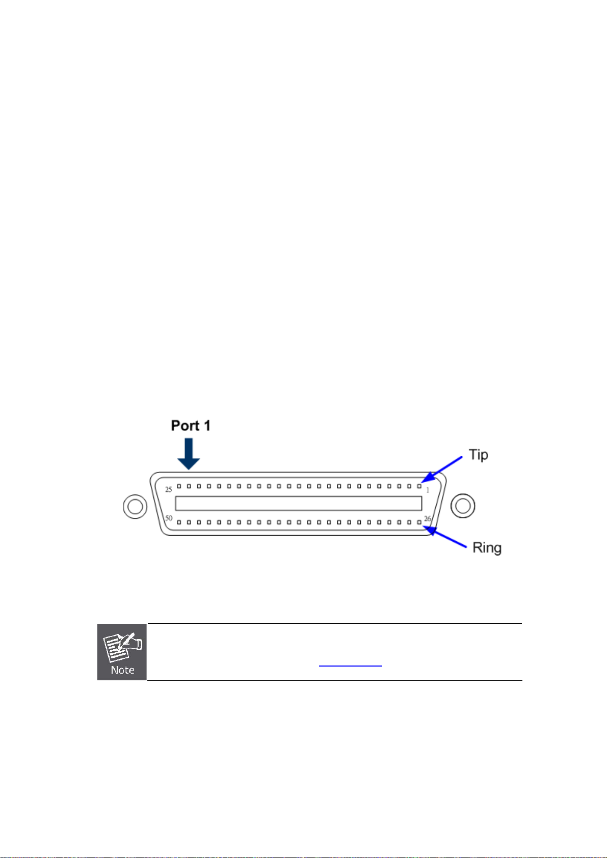
For the 24-Port VDSL or 24-PORT POTS, there are 24 pairs are used for tip and ring. The top row of the Telco RJ-21
connector is tip and the bottom row is ring. Figure 2-3-1 shows the pin out convention for the RJ-21 connector.
Figure 2-3-1 Pin out convention for the Telco RJ-21 connector of VC-2400MR series
To get the pin assignment of the VDSL/POTS port numbers to the pin numbers on the RJ-21
of the VC-2400MR series, please refer to APPENDIX A.3 for more detail.
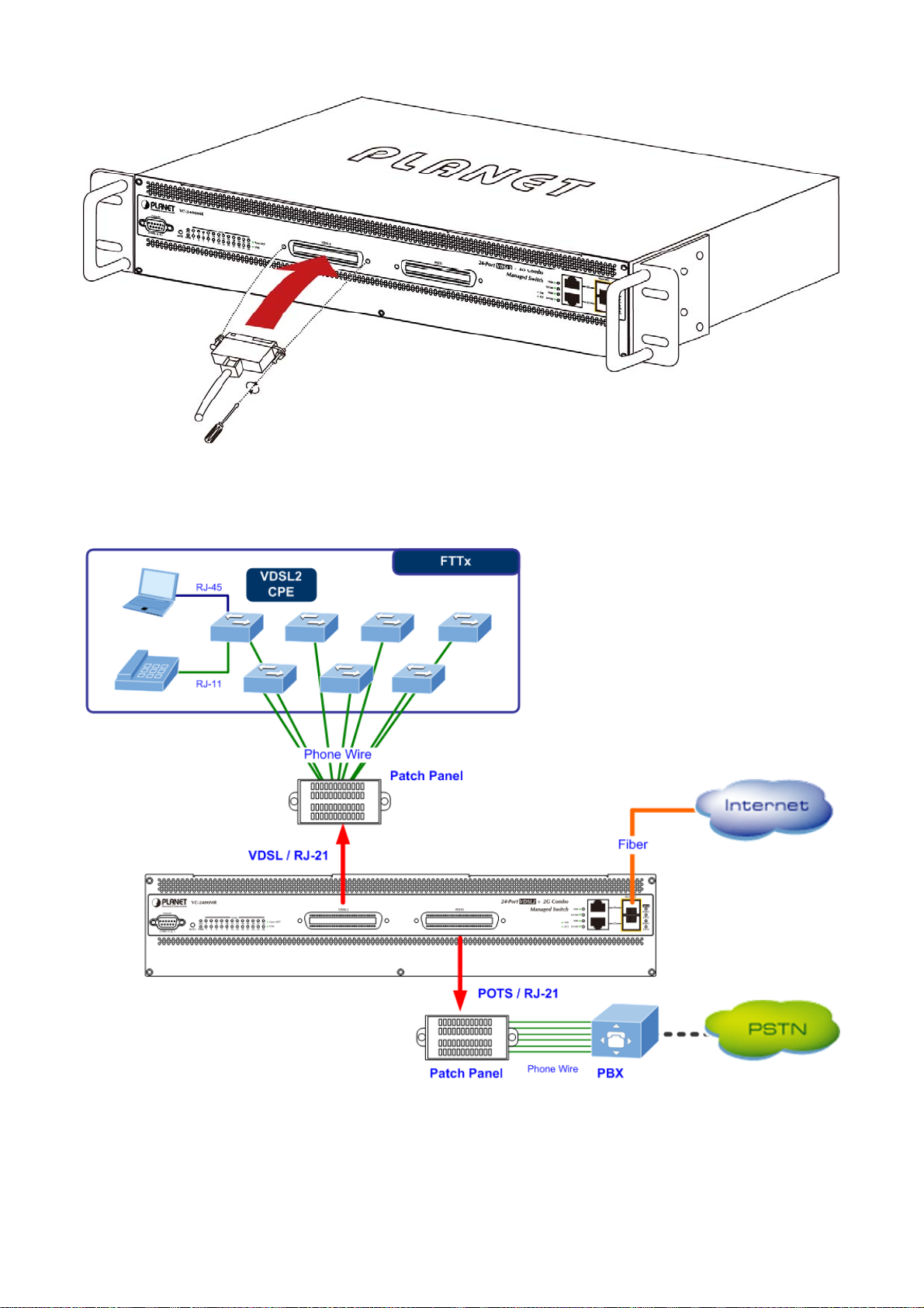
The VDSL port and POTS port of VC-2400MR series always connects to a patch panel. The connection between the
VC-2400MR series and the patch panel is made by an RJ-21 Category 5 Telco interface connector and cable, as shown in
Figure 2-3-2 and Figure 2-3-3.
29
Page 30
User’s Manual of VC-820M / VC-2400MR Series
Figure 2-3-2 Telco RJ-21 connect to VC-2400MR series
Figure 2-3-3: VC-2400MR Series VDSL2 connection
30
Page 31

User’s Manual of VC-820M / VC-2400MR Series
VC-820M VDSL2 connection
The VDSL2 port of VC-820M uses eight RJ-11 connectors which can be just directly connected to the remote CPEs through
existing telephone lines.
Figure 2-3-4: VC-820M VDSL2 connection
If the port is connected but the relevant LED is dark, check the following items:
1. The VDSL2 Switch and the connected device’s power are on or not.
2. The connecting cable is good and with correct type.
3. The cable is firmly seated in its connectors in the Managed Switch and in the associated device.
4. The connecting device, including any network adapter is well installed and functioning.
5. Confirm the CPE (VC-230 / VC-231 / VC-234) is set to CPE mode. Check the DIP switch at the rear panel.
6. Confirm the CPE (VC-231 / VC-234) device is implemented within the scope of operative without interference.
31
Page 32

User’s Manual of VC-820M / VC-2400MR Series
3. SWITCH MANAGEMENT
This chapter explains the methods that you can use to configure management access to the Managed Switch. It describes
the types of management applications and the communication and management protocols that deliver data between your
management device (work-station or personal computer) and the system. It also contains information about port connection
options.
This chapter covers the following topics:
Requirements
Management Access Overview
Administration Console Access
Web Management Access
SNMP Access
Standards, Protocols, and Related Reading
3.1 Requirements
Workstations of subscribers running Windows 98/ME, NT4.0, 2000/XP, MAC OS9 or later, Linux, UNIX or
other platform compatible with TCP/IP protocols.
Workstation installed with Ethernet NIC (Network Interface Card)
Ethernet Port connect
• Network cables - Use standard network (UTP) cables with RJ45 connectors.
Above Workstation installed with WEB Browser and JAVA runtime environment Plug-in
Serial Port connect
• Above PC with COM Port (DB-9 / RS-232) or USB-to-RS-232 converter
It is recommended to use Internet Explore 6.0 or above to access Managed Switch.
32
Page 33

User’s Manual of VC-820M / VC-2400MR Series
3.2 Management Access Overview
The Managed Switch gives you the flexibility to access and manage it using any or all of the following methods:
Web browser interface
An external SNMP-based network management application
An administration console
The administration console and Web browser interface support are embedded in the Managed Switch software and are
available for immediate use. Each of these management methods has their own advantages. Table 3-1 compares the three
management methods.
Method Advantages Disadvantages
Web Browser
SNMP Agent
Console
• Ideal for configuring the switch remotely
• Compatible with all popular browsers
• Can be accessed from any location
• Most visually appealing
• Communicates with switch functions at
the MIB level
• Based on open standards
• No IP address or subnet needed
• Text-based
• Telnet functionality and HyperTerminal
built into Windows
95/98/NT/2000/ME/XP operating
systems
• Secure
• Security can be compromised (hackers need
only know the IP address and subnet mask)
• May encounter lag times on poor connections
• Requires SNMP manager software
• Least visually appealing of all three methods
• Some settings require calculations
• Security can be compromised (hackers need
only know the community name)
• Must be near switch or use dial-up connection
• Not convenient for remote users
• Modem connection may prove to be unreliable
or slow
Table 3-1: Management Methods Comparison
33
Page 34
User’s Manual of VC-820M / VC-2400MR Series
3.3 Web Management
The Managed Switch offers management features that allow users to manage the Managed Switch from anywhere on the
network through a standard browser such as Microsoft Internet Explorer. After you set up your IP address for the switch,
you can access the Managed Switch's Web interface applications directly in your Web browser by entering the IP address
of the Managed Switch.
Figure 3-3-1 Web management
You can then use your Web browser to list and manage the Managed Switch configuration parameters from one central
location, just as if you were directly connected to the Managed Switch's console port. Web Management requires either
Microsoft Internet Explorer 6.0 or later, Safari or Mozilla Firefox 2.0 or later.
Figure 3-3-2 Web main screen of Managed Switch
34
Page 35

User’s Manual of VC-820M / VC-2400MR Series
3.4 SNMP-Based Network Management
You can use an external SNMP-based application to configure and manage the Managed Switch, such as SNMPc Network
Manager, HP Openview Network Node Management (NNM) or What’sup Gold. This management method requires the
SNMP agent on the switch and the SNMP Network Management Station to use the same community string. This
management method, in fact, uses two community strings: the get community string and the set community string. If the
SNMP Net-work management Station only knows the set community string, it can read and write to the MIBs. However, if it
only knows the get community string, it can only read MIBs.
Figure 3-4-1 SNMP management
3.5 Administration Console
The administration console is an internal, character-oriented, and command line user interface for performing system
administration such as displaying statistics or changing option settings. Using this method, you can view the administration
console from a terminal, personal computer, Apple Macintosh, or workstation connected to the switch's console (serial) port.
There are two ways to use this management method: via direct access or modem port access. The following sections
describe these methods. For more information about using the console, refer to Chapter 5 Console Management.
Figure 3-5-1 Console management
35
Page 36

User’s Manual of VC-820M / VC-2400MR Series
Direct Access
Direct access to the administration console is achieved by directly connecting a terminal or a PC equipped with a
terminal-emulation program (such as HyperTerminal) to the Managed Switch console (serial) port.
When using this management method, a straight DB9 RS-232 cable is required to connect the switch to the PC. After
making this connection, configure the terminal-emulation program to use the following parameters:
The default parameters are:
57600 bps
8 data bits
No parity
1 stop bit
Figure 3-5-2 Terminal parameter settings
You can change these settings, if desired, after you log on. This management method is often preferred because you can
remain connected and monitor the system during system reboots. Also, certain error messages are sent to the serial port,
regardless of the interface through which the associated action was initiated. A Macintosh or PC attachment can use any
terminal-emulation program for connecting to the terminal serial port. A workstation attachment under UNIX can use an
emulator such as TIP.
36
Page 37

User’s Manual of VC-820M / VC-2400MR Series
3.6 Protocols
The Managed Switch supports the following protocols:
Virtual terminal protocols, such as Telnet
Simple Network Management Protocol (SNMP)
3.6.1 Virtual Terminal Protocols
A virtual terminal protocol is a software program, such as Telnet, that allows you to establish a management session from a
Macintosh, a PC, or a UNIX workstation. Because Telnet runs over TCP/IP, you must have at least one IP address
configured on the Managed Switch before you can establish access to it with a virtual terminal protocol.
Terminal emulation differs from a virtual terminal protocol in that you must connect a terminal directly
to the console (serial) port.
To access the Managed Switch through a Telnet session:
1. Be Sure of the Managed Switch is configured with an IP address and the Managed Switch is reachable from a
PC.
2. Start the Telnet program on a PC and connect to the Managed Switch.
The management interface is exactly the same with RS-232 console management.
3.6.2 SNMP Protocol
Simple Network Management Protocol (SNMP) is the standard management protocol for multi-vendor IP networks. SNMP
supports transaction-based queries that allow the protocol to format messages and to transmit information between
reporting devices and data-collection programs. SNMP runs on top of the User Datagram Protocol (UDP), offering a
connectionless-mode service.
3.6.3 Management Architecture
All of the management application modules use the same Messaging Application Programming Interface (MAPI). By
unifying management methods with a single MAPI, configuration parameters set using one method (console port, for
example) are immediately displayable by the other management methods (for example, SNMP agent of Web browser).
The management architecture of the switch adheres to the IEEE open standard. This compliance assures customers that
the Managed Switch is compatible with, and will interoperate with other solutions that adhere to the same open standard.
37
Page 38

User’s Manual of VC-820M / VC-2400MR Series
4. Web-Based Management
This section introduces the configuration and functions of the Web-Based management.
4.1 About Web-based Management
The Managed Switch offers management features that allow users to manage the Managed Switch from anywhere on the
network through a standard browser such as Microsoft Internet Explorer.
The Web-Based Management supports Internet Explorer 6.0. It is based on Java Applets with an aim to reduce network
bandwidth consumption, enhance access speed and present an easy viewing screen.
By default, IE6.0 or later version does not allow Java Applets to open sockets. The user has to
explicitly modify the browser setting to enable Java Applets to use network ports.
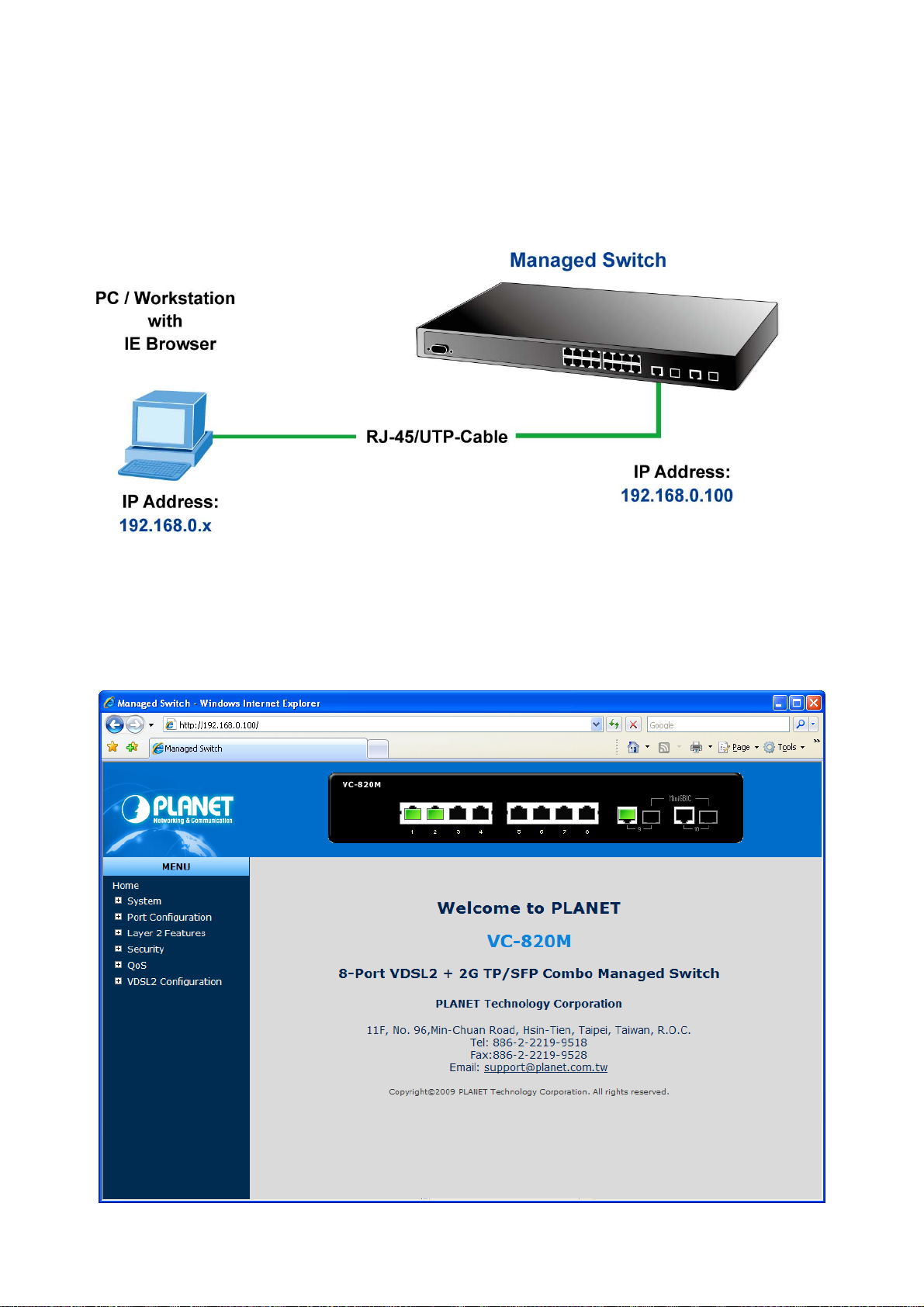
The Managed Switch can be configured through an Ethernet connection, make sure the manager PC must be set on same
the IP subnet address with the Managed Switch.
For example, the default IP address of the Managed Switch is 192.168.0.100, then the manager PC should be set at
192.168.0.x (where x is a number between 1 and 254, except 100), and the default subnet mask is 255.255.255.0.
If you have changed the default IP address of the Managed Switch to 192.168.1.1 with subnet mask 255.255.255.0 via
console, then the manager PC should be set at 192.168.1.x (where x is a number between 2 and 254) to do the relative
configuration on manager PC.
38
Page 39

User’s Manual of VC-820M / VC-2400MR Series
4.1.1 Requirements
• Workstations of subscribers running Windows 98/ME, NT4.0, 2000/2003/XP, MAC OS9 or later, Linux, UNIX or other
platform compatible with TCP/IP protocols.
• Workstation installed with Ethernet NIC (Network Card).
• Ethernet Port connect
¾ Network cables - Use standard network (UTP) cables with RJ45 connectors.
¾ Above PC installed with WEB Browser and JAVA runtime environment Plug-in.
It is recommended to use Internet Explore 6.0 or above to access VC-820M /VC-2400MR series
Managed Switch.
4.1.2 Logging on the switch
1. Use Internet Explorer 6.0 or above Web browser. Enter the factory-default IP address to access the Web interface.
The factory-default IP Address as following:
http://192.168.0.100
2. When the following login screen appears, please enter the default username “admin” with password “admin” (or the
username/password you have changed via console) to login the main screen of Managed Switch. The login screen in
Figure 4-1-1 appears.
Default User name: admin
Default Password: admin
Figure 4-1-1: Login screen
39
Page 40

User’s Manual of VC-820M / VC-2400MR Series
1. After entering the username and password, the main screen appears as Figure 4-1-2.
Figure 4-1-2: Web main page
2. The Switch Menu on the left of the Web page let you access all the commands and statistics the Switch provides.
Now, you can use the Web management interface to continue the switch management or manage the Managed Switch by
Web interface. The Switch Menu on the left of the web page let you access all the commands and statistics the Managed
Switch provides.
1. It is recommended to use Internet Explore 6.0 or above to access Managed Switch.
2. The changed IP address take effect immediately after click on the Apply button, you need
to use the new IP address to access the Web interface.
3. For security reason, please change and memorize the new password after this first setup.
4. The WEB configuration and CLI command of VC-820M are the same with VC-2400MR
series except Power/Fan module detection feature, so the VC-820M will be the example to
describe how to configure switch and also, will describe PoE configuration in additional.
40
Page 41

User’s Manual of VC-820M / VC-2400MR Series
4.1.3 Main WEB PAGE
The Managed Switch provides a Web-based browser interface for configuring and managing it. This interface allows you to
access the Managed Switch using the Web browser of your choice. This chapter describes how to use the Managed
Switch’s Web browser interface to configure and manage it.
VDSL Port Link Status
Copper Port Link Status
SFP Port Link Status
Main Screen
Main Functions Menu
Panel Display
The web agent displays an image of the Managed Switch’s ports. The Mode can be set to display different information for
the ports, including Link up or Link down. Clicking on the image of a port opens the Port Statistics page.
The port states are illustrated as follows:
State Disabled Down Link
RJ-45 Ports
SFP Ports
Figure 4-1-3: Main Page
41
Page 42

User’s Manual of VC-820M / VC-2400MR Series
Main Menu
Using the onboard web agent, you can define system parameters, manage and control the Managed Switch, and all its
ports, or monitor network conditions. Via the Web-Management, the administrator can setup the Managed Switch by select
the functions those listed in the Main Function. The screen in Figure 4-1-4 appears.
Figure 4-1-4: VC-820M / VC-2400MR series Managed Switch Main Functions Menu
4.2 System
Use the System menu items to display and configure basic administrative details of the Managed Switch. Under System the
following topics are provided to configure and view the system information: This section has the following items:
■ System Information Provides basic system description, including contact information.
■ IP Configuration Sets the IP address for management access.
■ Console Information Displays the required console settings on the Managed Switch.
■ SNMP Configuration Configure SNMP agent and SNMP Trap.
■ Syslog Setting Configure logging of messages and assign IP address of remote Syslog
servers.
■ Firmware Upgrade Upgrade the firmware via TFTP server or Web Brower file transfer.
■ Configuration Backup Save/view the Managed Switch configuration to remote host.
Upload the switch configuration from remote host.
■ Factory Default Reset the configuration of the Managed Switch.
■ System Reboot Restarts the Managed Switch.
42
Page 43

User’s Manual of VC-820M / VC-2400MR Series
4.2.1 System Information
In System information, it has two parts of setting – Basic and Misc Config. We will describe the configure detail in
following.
4.2.1.1 Basic
The Basic System Info page provides information for the current device information. Basic System Info page helps a switch
administrator to identify the model name, firmware / hardware version and MAC address. The screen in Figure 4-2-1
appears.
Figure 4-2-1: Basic System Information screenshot
The page includes the following fields:
Object Description
Model Name:
Description:
MAC Address:
Firmware Version:
Hardware Version:
Build Firmware Date:
Display the system name of the Managed Switch.
Describes the Managed Switch.
Displays the unique hardware address assigned by manufacturer (default).
Displays the Managed Switch’s firmware version.
Displays the Managed Switch’s hardware version.
Displays the date information of the firmware.
43
Page 44
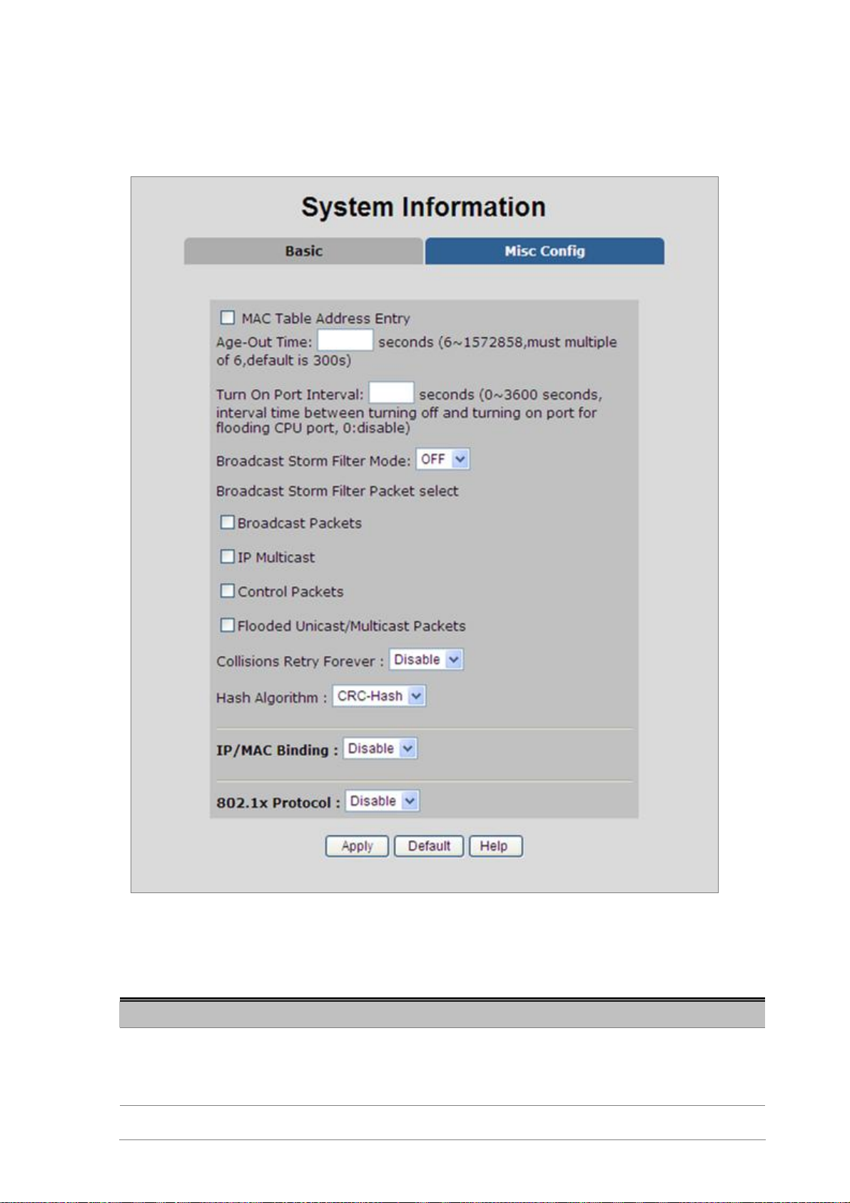
User’s Manual of VC-820M / VC-2400MR Series
4.2.1.2 Misc Config
Choose Misc Config from System Information of Managed Switch, the screen in Figure 4-2-2 appears.
The page includes the following fields:
Object Description
MAC Address Age-out
Time
Broadcast Storm Filter
Figure 4-2-2: Switch Misc Config screenshot
Type the number of seconds that an inactive MAC address remains in the
switch’s address table. The value is a multiple of 6.
Default is 300 seconds.
To configure broadcast storm control, enable it and set the upper threshold for
44
Page 45

User’s Manual of VC-820M / VC-2400MR Series
Mode
Broadcast Storm Filter
Packets Select
Collision Retry Forever
individual ports. The threshold is the percentage of the port’s total bandwidth
used by broadcast traffic. When broadcast traffic for a port rises above the
threshold you set, broadcast storm control becomes active.
The valid threshold values are 1/2, 1/4, 1/8, 1/16 and OFF.
Default is “OFF”.
To select broadcast storm Filter Packets type. If no packets type by selected,
mean can not filter any packets .The Broadcast Storm Filter Mode will show OFF.
The selectable items as below:
• Broadcast Packets
• IP Multicast
• Control Packets
• Flooded Unicast / Multicast Packets
Provide Collision Retry Forever function”Disable” or 16, 32, 48 collision numbers
on Managed Switch. If this function is disabled, when a packet meet a collision,
the Managed Switch will retry 6 times before discard the packets. Otherwise, the
Managed Switch will retry until the packet is successfully sent.
Default value is 16.
Provide MAC address table Hashing setting on Managed Switch; available
Hash Algorithm
IP/MAC Binding Enable / Disable IP MAC Binding function.
802.1x protocol Enable / Disable 802.1x protocols.
Apply button
options are CRC-Hash and DirectMap.
Default mode is CRC-Hash.
Press the button to complete the configuration.
4.2.1.3 Module Info
This section provides current status of power supply unit from VC-2400MR series, the screen in Figure 4-2-3 appears and
table 4-2-1 describes the power and fan module Status object of VC-2400MR series.
45
Page 46
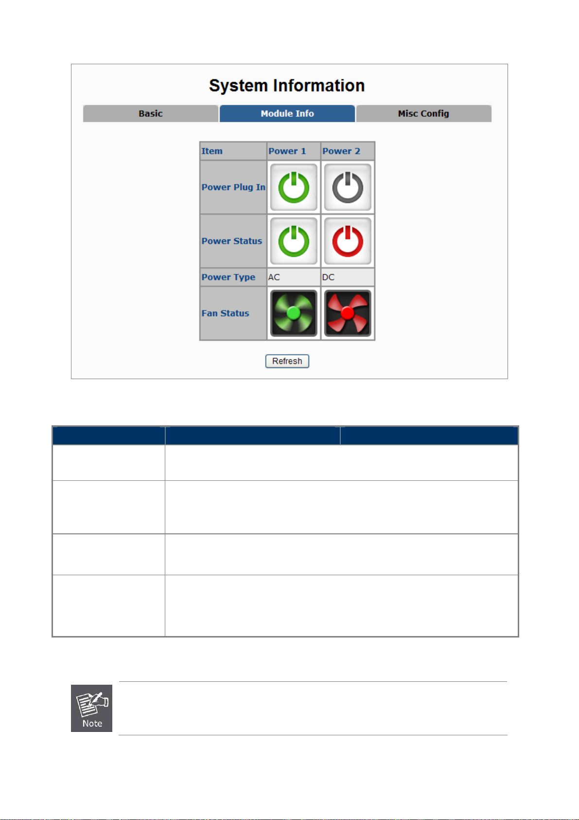
User’s Manual of VC-820M / VC-2400MR Series
Figure 4-2-3 Chassis Status Web Page Screen
Item Power 1 Power 2
Power on
Power Status
Power Type
Fan Status
Gray: indicate the power supply unit not install into the VC-2400MR series.
Green: indicate the power supply unit install into the VC-2400MR series.
Gray: indicate the power supply unit not install into the VC-2400MR series.
Green: indicate the power supply unit has power.
Red: indicate the power supply unit has no power or failure.
AC: indicate the AC power supply unit (VC-RPS200) install into the VC-2400MR series.
DC: indicate the DC power supply unit (VC-RPS48) install into the VC-2400MR series.
Gray: indicate the power supply unit not install into the VC-2400MR series.
Green: indicate the fan is operation normally.
Red: indicate the fan is failure.
Table 4-2-1 Descriptions of the Chassis Status Web Page Screen Objects
Once, installed the AC or DC power supply unit into VC-2400MR
Even, the AC or DC power supply unit has no power.
46
series, the fan will start to working.
Page 47

User’s Manual of VC-820M / VC-2400MR Series
4.2.2 IP Configuration
The Managed Switch is a network device which needs to be assigned an IP address for being identified on the network.
Users have to decide a means of assigning IP address to the Managed Switch.
IP address overview
What is an IP address?
Each device (such as a computer) which participates in an IP network needs a unique "address" on the network. It's similar
to having a US mail address so other people have a know way to send you messages. An IP address is a four byte number,
which is usually written in "dot notation" - each of the bytes' decimal value is written as a number, and the numbers are
separated by "dots" (aka periods). An example: 199.25.123.1
How do I get one for this box?
The IP addresses on most modern corporate nets are assigned by an employee called a "Network Administrator", or "Sys.
Admin". This person assigns IP addresses and is responsible for making sure that IP addresses are not duplicated - If this
happens one or both machines with a duplicate address will stop working.
Another possibility is getting your address assigned to you automatically over the net via DHCP protocol. Enable DHCP
function, and reset the machine. If your network is set up for this service, you will get an IP address assigned over the
network. If you don't get an address in about 30 seconds, you probably don't have DHCP.
IP Configuration
The IP Configuration includes the IP Address, Subnet Mask and Gateway. The Configured column is used to view or
change the IP configuration. Fill up the IP Address, Subnet Mask and Gateway for the device. The screen in Figure 4-2-4
appears.
Figure 4-2-4: IP configuration interface
47
Page 48

The page includes the following fields:
Object Description
DHCP
IP Address
User’s Manual of VC-820M / VC-2400MR Series
Enable or disable the DHCP client function.
When DHCP function is enabled, the Managed Switch will be assigned an IP
address from the network DHCP server. The default IP address will be replaced
by the assigned IP address on DHCP server. After the user clicks Apply, a
popup dialog shows up to inform the user that when the DHCP client is enabled,
the current IP will lose and user should find the new IP on the DHCP server.
Assign the IP address that the network is using.
If DHCP client function is enabled, this switch is configured as a DHCP client.
The network DHCP server will assign the IP address to the switch and display it
in this column.
The default IP is 192.168.0.100 or the user has to assign an IP address
manually when DHCP Client is disabled.
Assign the subnet mask to the IP address.
Subnet Mask
Gateway
If DHCP client function is disabled, the user has to assign the subnet mask in
this column field.
Assign the network gateway for the switch.
If DHCP client function is disabled, the user has to assign the gateway in this
column field.
The default gateway is 192.168.0.254.
48
Page 49

User’s Manual of VC-820M / VC-2400MR Series
4.2.3 Console Information
Console is a standard UART interface to communicate with Serial Port. You can use Windows HyperTerminal program to
link the Managed Switch. The page displays the required console settings on the Managed Switch.
Figure 4-2-5: Console Information interface
4.2.4 SNMP Configuration
4.2.4.1 SNMP Overview
The Simple Network Management Protocol (SNMP) is an application layer protocol that facilitates the exchange of
management information between network devices. It is part of the Transmission Control Protocol/Internet Protocol (TCP/IP)
protocol suite. SNMP enables network administrators to manage network performance, find and solve network problems,
and plan for network growth.
An SNMP-managed network consists of three key components: Network management stations (NMSs), SNMP agents,
Management information base (MIB) and network-management protocol:
Network management stations (NMSs):Sometimes called consoles, these devices execute management
applications that monitor and control network elements. Physically, NMSs are usually engineering
workstation-caliber computers with fast CPUs, megapixel color displays, substantial memory, and abundant disk
space. At least one NMS must be present in each managed environment.
Agents:Agents are software modules that reside in network elements. They collect and store management
information such as the number of error packets received by a network element.
Management information base (MIB):A MIB is a collection of managed objects residing in a virtual information
store. Collections of related managed objects are defined in specific MIB modules.
network-management protocol:A management protocol is used to convey management information between
agents and NMSs. SNMP is the Internet community's de facto standard management protocol.
SNMP Operations
SNMP itself is a simple request/response protocol. NMSs can send multiple requests without receiving a response.
49
Page 50

User’s Manual of VC-820M / VC-2400MR Series
Get -- Allows the NMS to retrieve an object instance from the agent.
Set -- Allows the NMS to set values for object instances within an agent.
Trap -- Used by the agent to asynchronously inform the NMS of some event. The SNMPv2 trap message is
designed to replace the SNMPv1 trap message.
SNMP community
An SNMP community is the group that devices and management stations running SNMP belong to. It helps define where
information is sent. The community name is used to identify the group. A SNMP device or agent may belong to more than
one SNMP community. It will not respond to requests from management stations that do not belong to one of its
communities. The normal SNMP default communities are as below when configured:
Write = private
Read = public
4.2.4.2 System Options
Use this page to define management stations. You can also define a name, location, and contact person for the Managed
Switch.
Figure 4-2-6: SNMP configuration interface
The page includes the following fields:
Object Description
System Name
System Location
System Contact
An administratively assigned name for this managed node. By convention, this is
the node's fully-qualified domain name. A domain name is a text string drawn
from the alphabet (A-Za-z), digits (0-9), minus sign (-). No space characters are
permitted as part of a name. The first character must be an alpha character. And
the first or last character must not be a minus sign.
The allowed string length is 0 to 255.
The physical location of this node (e.g., telephone closet, 3rd floor).
The textual identification of the contact person for this managed node, together
with information on how to contact this person.
50
Page 51

User’s Manual of VC-820M / VC-2400MR Series
A
SNMP Status
Indicates the SNMP mode operation. Possible modes are:
• Enabled: Enable SNMP mode operation.
• Disabled: Disable SNMP mode operation.
4.2.4.3 Community Strings
Community strings serve as passwords and can be entered as one of the following:
Figure 4-2-7: Community strings interface
The page includes the following fields:
Object Description
Community Strings: Here you can define the new community string set and remove the unwanted
dd
button
Remove
button
community string.
String: Fill the name string.
RO: Read only. Enables requests accompanied by this community string to
display MIB-object information.
RW: Read/write. Enables requests accompanied by this community string to
display MIB-object information and to set MIB objects.
Press the button to add the management SNMP community strings on the
Managed Switch.
Press the button to remove the management SNMP community strings that you
defined before on the Managed Switch.
51
Page 52

User’s Manual of VC-820M / VC-2400MR Series
4.2.4.4 Trap Managers
A trap manager is a management station that receives the trap messages generated by the switch. If no trap manager is
defined, no traps will be issued. To define a management station as a trap manager, assign an IP address, enter the SNMP
community strings, and select the SNMP trap version.
Figure 4-2-8: Trap Managers interface
The page includes the following fields:
Object Description
IP Address:
Community:
Enter the IP address of the trap manager.
Enter the community string for the trap station.
4.2.4.5 SNMPv3 Groups
Configure SNMPv3 groups table on this page. The entry index keys are Security Model and Security Name.
The SNMPv3 Groups Configuration screen in Figure 4-2-9 appears.
Figure 4-2-9: SNMP configuration interface
52
Page 53

The page includes the following fields:
Object Description
Group Name:
User’s Manual of VC-820M / VC-2400MR Series
A string identifying the group name that this entry should belong to.
The allowed string length is 1 to 15.
V1 | V2c | USM
Security Name:
Remove
Indicates the security model that this entry should belong to. Possible security
models are:
• v1: Reserved for SNMPv1.
• v2c: Reserved for SNMPv2c.
• usm: User-based Security Model (USM).
A string identifying the security name that this entry should belong to.
The allowed string length is 1 to 15.
Check to delete the entry. It will be deleted during the next save.
4.2.4.6 SNMPv3 View
Configure SNMPv3 views table on this page. The entry index keys are View Name and OID Subtree.
The SNMPv3 Views Configuration screen in Figure 4-2-10 appears.
The page includes the following fields:
Object Description
View N ame:
Included | Excluded:
Figure 4-2-10: SNMP configuration interface
A string identifying the view name that this entry should belong to.
The allowed string length is 1 to 15.
Indicates the view type that this entry should belong to. Possible view type are:
53
Page 54

User’s Manual of VC-820M / VC-2400MR Series
• included: An optional flag to indicate that this view subtree should be
included.
• excluded: An optional flag to indicate that this view subtree should be
excluded.
View Subtree
View Mask(Hexadecimal
Digits):
The OID defining the root of the subtree to add to the named view. The allowed
OID length is 1 to 128. The allowed string content is digital number or asterisk(*)
View mask is defined in order to reduce the amount of configuration information
required when fine-grained access control is required (e.g., access control at
the object instance level)
4.2.4.7 SNMPv3 Access
Configure SNMPv3 accesses table on this page. The entry index keys are Group Name, Security Model and Security Level.
The SNMPv3 Accesses Configuration screen in Figure 4-2-11 appears.
The page includes the following fields:
Object Description
Group Name:
V1 | V2c | USM:
SNMP Access:
Figure 4-2-11: SNMP configuration interface
A string identifying the group name that this entry should belong to.
The allowed string length is 1 to 15.
Indicates the security model that this entry should belong to. Possible security
models are:
• v1: Reserved for SNMPv1.
• v2c: Reserved for SNMPv2c.
• usm: User-based Security Model (USM)
Indicates the security model that this entry should belong to. Possible security
models are:
54
Page 55

User’s Manual of VC-820M / VC-2400MR Series
A
• NoAuth: None authentication and none privacy.
• Auth: Authentication and none privacy.
• Authpriv: Authentication and privacy.
The name of the MIB views defining the MIB objects for which this request may
Read View:
Write View:
Notify View:
dd
button
Remove
button
request the current values.
The allowed string length is 1 to 16.
The name of the MIB views defining the MIB objects for which this request may
potentially SET new values.
The allowed string length is 1 to 16.
Set up the notify view.
Press the button to add the management SNMP community strings on the
Managed Switch.
Check to delete the selected entry. It will be deleted during the next save.
4.2.4.8 SNMP V3 usm-user
Configure SNMPv3 users table on this page. The entry index keys are Engine ID and User Name.
The SNMPv3 Users Configuration screen in Figure 4-2-12 appears.
Figure 4-2-12: SNMP configuration interface
The page includes the following fields:
Object Description
SNMP User Name:
Auth Type:
A string identifying the user name that this entry should belong to. The allowed
string length is 1 to 15.
Indicates the authentication protocol that this entry should belong to. Possible
authentication protocol are:
55
Page 56

User’s Manual of VC-820M / VC-2400MR Series
A
• None: None authentication protocol.
• MD5: An optional flag to indicate that this user using MD5 authentication
protocol.
The value of security level cannot be modified if entry already exists. That means
must first ensure that the value is set correctly.
Auth Key(8~32):
Private Key(8~32):
dd
button
Remove
button
A string identifying the authentication pass phrase.
For MD5 authentication protocol, the allowed string length is 8 to 32.
A string identifying the privacy pass phrase.
The allowed string length is 8 to 32.
Press the button to add the management SNMP community strings on the
Managed Switch.
Check to delete the selected entry. It will be deleted during the next save.
56
Page 57

User’s Manual of VC-820M / VC-2400MR Series
4.2.5 Syslog Setting
The Syslog Setting page allows you to configure the logging of messages that are sent to remote syslog servers or other
management stations. You can also limit the event messages sent to only those messages below a specified level.
Figure 4-2-13: Syslog Setting web interface
The page includes the following fields:
Object Description
Syslog Server IP
Log level • None: No send syslog message to syslog server, and Max Age parameters
IP address of syslog server.
of the root bridge, regardless of how it is configured.
• Major: only send major syslog to syslog server, eg: link up/down, system
warm/cold start
• All: send all syslog messages to syslog server.
57
Page 58

User’s Manual of VC-820M / VC-2400MR Series
4.2.6 SNTP Setting
The Simple Network Time Protocol (SNTP) allows user could configure the Managed Switch to send time synchronization
requests to specific time servers (i.e., client mode) by IP address.
The page includes the following fields:
Object Description
SNTP
SNTP server IP
UTC Type
Time Range (0~24)
Time
Enable or Disable SNTP Feature.
Allows to assign a SNTP sever IP address here.
Allows user to select time zone. Ex. If your location is in Taipei (UTC+08) then
You have to choose After-UTC. If your location is in San Francisco (UTC-08) then
you have to choose Before-UCT.
Allows user input time range. Ex. if time zone is UTC+08 is then input 8, if time
zone is UTC-05 then input 5.
Shows current time after connected to NTP server.
Figure 4-2-14: SNTP Setting web interface
58
Page 59

User’s Manual of VC-820M / VC-2400MR Series
4.2.7 Firmware Upgrade
It provides the functions allowing the user to update the switch firmware via the Trivial File Transfer Protocol (TFTP)
server. Before updating, make sure the TFTP server is ready and the firmware image is located on the TFTP server.
4.2.7.1 TFTP Firmware Upgrade
The Firmware Upgrade page provides the functions to allow a user to update the Managed Switch firmware from the TFTP
server in the network. Before updating, make sure you have your TFTP server ready and the firmware image is on the
TFTP server. The screen in Figure 4-2-13 appears.
Use this menu to download a file from specified TFTP server to the Managed Switch.
Figure 4-2-15: Firmware Upgrade interface
The page includes the following fields:
Object Description
TFTP Server IP Address: Type in your TFTP server IP.
Firmware File Name: Type in the name of the firmware image file to be updated.
59
Page 60
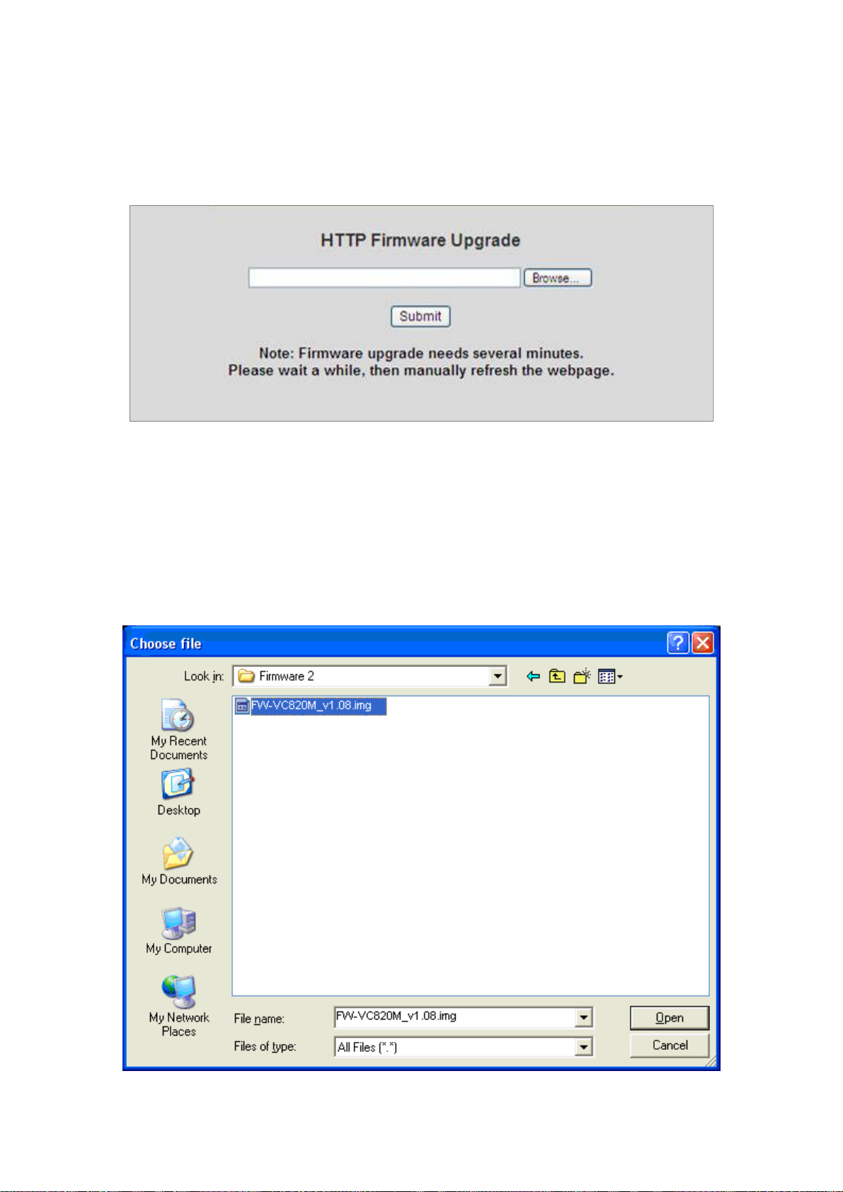
User’s Manual of VC-820M / VC-2400MR Series
4.2.7.2 HTTP Firmware Upgrade
The HTTP Firmware Upgrade page contains fields for downloading system image files from the Local File browser to the
device. The Web Firmware Upgrade screen in Figure 4-2-14 appears.
Figure 4-2-16: HTTP Firmware Upgrade interface
To open Firmware Upgrade screen perform the following:
1. Click System -> Web Firmware Upgrade.
2. The Firmware Upgrade screen is displayed as in Figure 4-2-14.
3. Click the “Browse” button of the main page, the system would pop up the file selection menu to choose firmware.
Figure 4-2-17: HTTP Firmware Upgrade selection window
60
Page 61
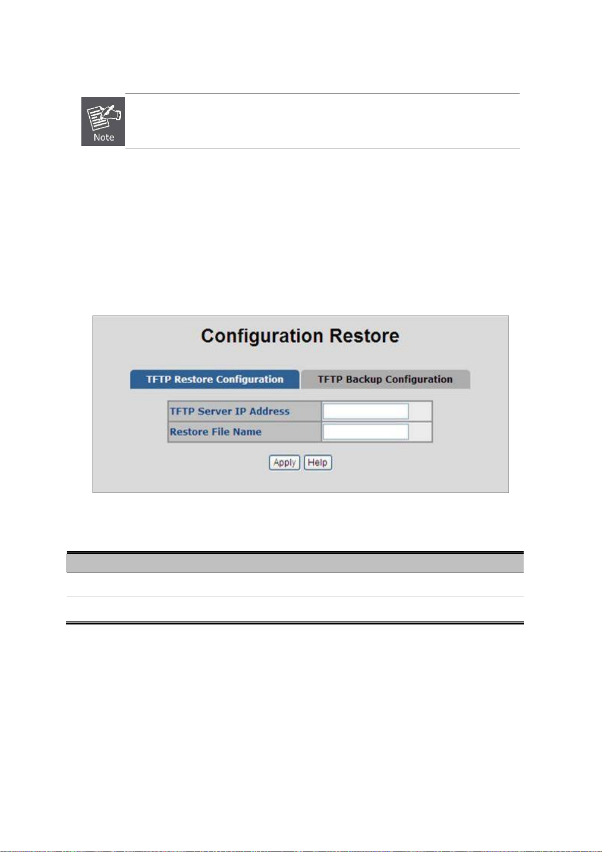
User’s Manual of VC-820M / VC-2400MR Series
4. Select on the firmware then click “Submit”, the Software Upload Progress would show the file upload status.
Firmware upgrade needs several minutes. Please wait a while, and then manually
refresh the webpage.
4.2.8 Configuration Backup
4.2.8.1 TFTP Restore Configuration
You can restore a previous backup configuration from the TFTP server to recover the settings. Before doing that, you must
locate the image file on the TFTP server first and the Managed Switch will download back the flash image.
Figure 4-2-18: TFTP Configuration Restore interface
The page includes the following fields:
Object Description
TFTP Server IP Address:
Restore File Name:
Type in the TFTP server IP.
Type in the correct file name for restoring.
61
Page 62

User’s Manual of VC-820M / VC-2400MR Series
4.2.8.2 HTTP Config File Restore
You can also restore the previous backup configuration from the current workstation utilize internet browser such as
Microsoft Internet Explore or Mozila Firefox, to recover the settings. Before doing that, you must locate the image file on the
local management station first and the Managed Switch will download back the flash image
Figure 4-2-19: HTTP Configuration Restore interface
4.2.8.3 TFTP Backup Configuration
You can back up the current configuration from flash ROM to the TFTP server for the purpose of recovering the
configuration later. It helps you to avoid wasting time on configuring the settings by backing up the configuration.
Figure 4-2-20: TFTP Configuration Backup interface
The page includes the following fields:
Object Description
TFTP Server IP Address:
Backup File Name:
Type in the TFTP server IP.
Type in the file name that will be backup on the TFTP server.
62
Page 63

User’s Manual of VC-820M / VC-2400MR Series
4.2.8.4 HTTP Config File Backup
This function allows backup the current configuration of the Managed Switch to the local management station. The screens
in Figure 4-2-19 and Figure 4-2-20 appear.
Figure 4-2-21: HTTP configuration file backup interface
Move the cursor to “Click here to download configuration file” and click. The backup configuration file will be packaged as a
“config.tar” file as default.
Figure 4-2-22: HTTP Configuration Backup window
63
Page 64

User’s Manual of VC-820M / VC-2400MR Series
4.2.9 Factory Default
Reset switch to default configuration. Click to reset all configurations to the default value.
4.2.10 System Reboot
Reboot the switch in software reset. Click
Figure 4-2-23: Factory Default interface
Reboot
to reboot the system.
Figure 4-2-24: System Reboot interface
64
Page 65

User’s Manual of VC-820M / VC-2400MR Series
4.3 Port Configuration
Use the Port Configuration Menu to display or configure the Managed Switch’s ports. This section has the following items:
Port Control
Port Status
Port Statistics
Port Sniffer
Protected Port
Configures port connection settings
Display the current Port link status and speed etc.
Lists Ethernet and RMON port statistics
Sets the source and target ports for mirroring
Configures Protected Ports and groups
4.3.1 Port Control
In Port control you can configure the settings of each port to control the connection parameters, and the status of each port
is listed beneath.
The page includes the following fields:
Object Description
Port:
State:
Negotiation:
Speed:
Figure 4-3-1: Port Control interface
Use the scroll bar and click on the port number to choose the port to be
configured.
Current port state. The port can be set to disable or enable mode. If the port state
is set as ‘Disable’, it will not receive or transmit any packet.
The item is only for Gigabit ports of the Managed Switch.
Auto and Force. Being set as Auto, the speed and duplex mode are negotiated
automatically. When you set it as Force, you have to set the speed and duplex
mode manually.
The item is only for Gigabit ports of the Managed Switch.
It is available for selecting when the Negotiation column is set as Force. When
65
Page 66

User’s Manual of VC-820M / VC-2400MR Series
the Negotiation column is set as Auto, this column is read-only.
The item is only for Gigabit ports of the Managed Switch.
Duplex:
Flow Control:
Rate Control:
(Unit: 128KBbps)
It is available for selecting when the Negotiation column is set as Force. When
the Negotiation column is set as Auto, this column is read-only.
Whether or not the receiving node sends feedback to the sending node is
determined by this item. When enabled, once the device exceeds the input data
rate of another device, the receiving device will send a PAUSE frame which halts
the transmission of the sender for a specified period of time. When disabled, the
receiving device will drop the packet if too much to process.
The item is only for Gigabit ports of the Managed Switch.
Supports by-port ingress and egress rate control.
For example, assume port 1 is 10Mbps, users can set its effective egress rate at
1Mbps and ingress rate at 500Kbps. Device will perform flow control or
backpressure to confine the ingress rate to meet the specified rate.
Ingress: Type the port effective ingress rate.
The valid range is 0 ~ 8000. The unit is 128K.
0: disable rate control.
1 ~ 8000: valid rate value
Egress: Type the port effective egress rate.
The valid range is 0 ~ 8000. The unit is 128K.
0: disable rate control.
1 ~8000: valid rate value.
A port in security mode will be “locked” without permission of address learning.
Only the incoming packets with SMAC already existing in the address table can
Security:
BSF:
Jumbo Frame:
be forwarded normally.
User can disable the port from learning any new MAC addresses, then use the
static MAC addresses screen to define a list of MAC addresses that can use the
secure port. Enter the settings, then click Apply button to change on this page.
User can disable/Enable port broadcast storm filtering option by port.
The filter mode and filter packets type can be select in Switch Setting > Misc
Config page.
User can disable/Enable port jumbo frame option by port. When port jumbo
frame is enable, the port forward jumbo frame packet.
The Managed Switch support up to 9Kbytes jumbo frame forwarding.
66
Page 67

User’s Manual of VC-820M / VC-2400MR Series
4.3.2 Port Status
This page displays current port configurations and operating status - it is a ports’ configurations summary table. Via the
summary table, you can know status of each port clear at a glance, like Port Link Up/Link Down status, negotiation, Link
Speed, Rate Control, Duplex mode and Flow Control.
Figure 4-3-2: Port Status interface
4.3.3 Port Statistics
The following chart provides the current statistic information which displays the real-time packet transfer status for each port.
The user might use the information to plan and implement the network, or check and find the problem when the collision or
heavy traffic occurs.
Figure 4-3-3: Port Statistics interface
67
Page 68

The page includes the following fields:
Object Description
User’s Manual of VC-820M / VC-2400MR Series
Port:
State:
Link: The status of linking—‘Up’ or ‘Down’.
Tx Good Packet:
Tx Bad Packet:
Rx Good Packet:
Rx Bad Packet:
Tx Abort Packet:
Packet Collision:
Packet Dropped:
The port number.
It’s set by Port Control. When the state is disabled, the port will not transmit or
receive any packet.
The counts of transmitting good packets via this port.
The counts of transmitting bad packets (including undersize [less than 64 octets],
oversize, CRC Align errors, fragments and jabbers packets) via this port.
The counts of receiving good packets via this port.
The counts of receiving good packets (including undersize [less than 64 octets],
oversize, CRC error, fragments and jabbers) via this port.
The aborted packet while transmitting.
The counts of collision packet.
The counts of dropped packet.
4.3.4 Port Sniffer
The Port Sniffer (mirroring) is a method for monitor traffic in switched networks. Traffic through a port can be monitored by
one specific port. That is, traffic goes in or out a monitored port will be duplicated into sniffer port.
Figure 4-3-4: Port Mirror application
68
Page 69

User’s Manual of VC-820M / VC-2400MR Series
Configuring the port mirroring by assigning a source port from which to copy all packets and a destination port where those
packets will be sent.
The page includes the following fields:
Object Description
Select a sniffer mode:
Sniffer Type:
It’ means Analysis port can be used to see the traffic on another port you want to
Analysis (Monitoring) Port:
Monitored Port:
monitor. You can connect Analysis port to LAN analyzer or netxray.
The port you want to monitor. The monitor port traffic will be copied to Analysis
port. You can select one monitor ports in the switch. User can choose which port
that they want to monitor in only one sniffer type.
Figure 4-3-5: Port Sniffer interface
• DISABLE
• RX
• TT
• BOTH
1 When the Mirror Mode set to RX or TX and the Analysis Port be selected, the packets
to and from the Analysis Port will not be transmitted. The Analysis Port will accept only
COPIED packets from the Monitored Port.
2 If you want to disable the function, you must select monitor port to none.
69
Page 70
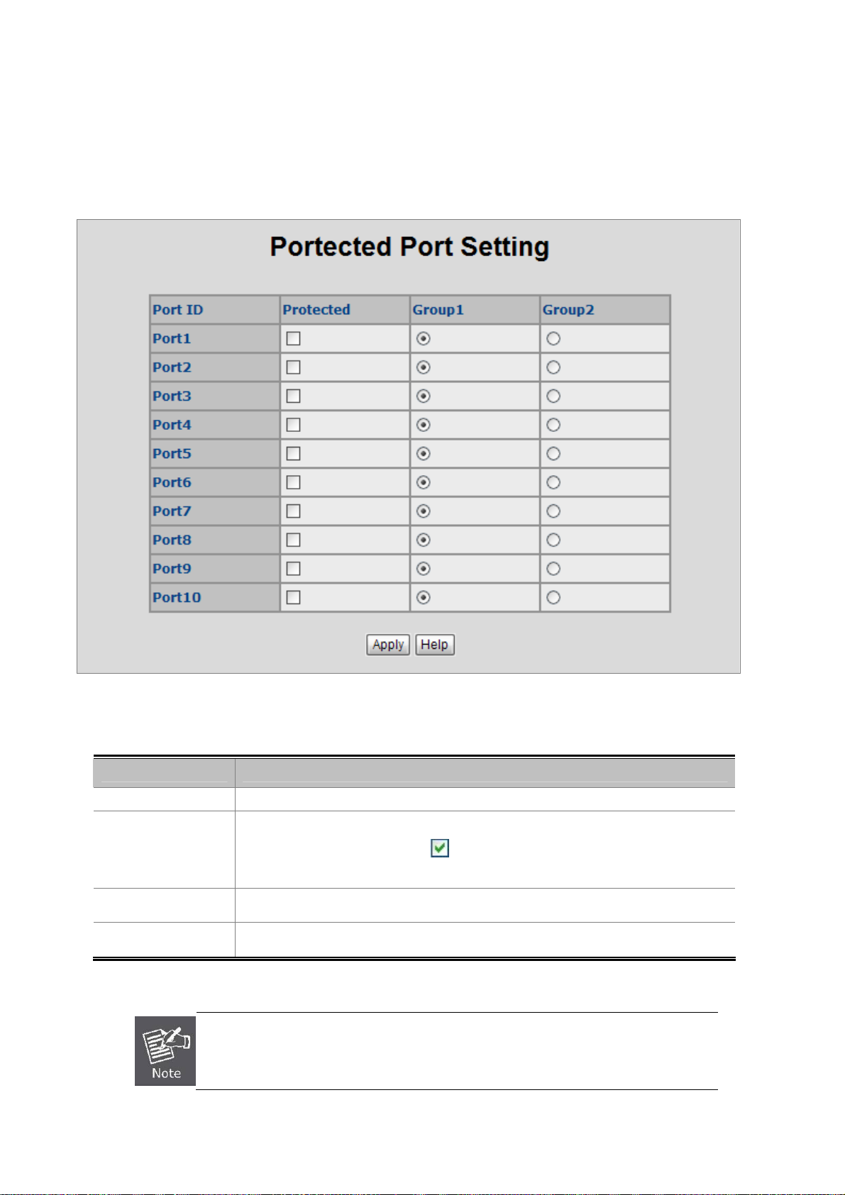
User’s Manual of VC-820M / VC-2400MR Series
4.3.5 Protect Port
There are two protected port groups; ports in different groups can't communicate.
In the same group, protected ports can't communicate with each other, but can communicate with unprotected ports.
Unprotected ports can communicate with any ports, including protected ports.
Figure 4-3-6: Protected Port Setting Web interface
The page includes the following fields:
Object Description
Port ID Identify the Managed Switch interface.
Enable the Protected function on the selected port.
Protected
Group 1
Group 2
Usually, set the Uplink port or the Port is connected to Core switch or router to be the
Un-protected port.
If the check box is not shown as
communicate with any ports - including protected ports
Set the protected port to be Group 1 member.
Set the protected port to be Group 2 member.
, then this port a unprotected port and it can
70
Page 71

User’s Manual of VC-820M / VC-2400MR Series
4.4 VLAN configuration
4.4.1 VLAN Overview
A Virtual Local Area Network (VLAN) is a network topology configured according to a logical scheme rather than the
physical layout. VLAN can be used to combine any collection of LAN segments into an autonomous user group that
appears as a single LAN. VLAN also logically segment the network into different broadcast domains so that packets are
forwarded only between ports within the VLAN. Typically, a VLAN corresponds to a particular subnet, although not
necessarily.
VLAN can enhance performance by conserving bandwidth, and improve security by limiting traffic to specific domains.
A VLAN is a collection of end nodes grouped by logic instead of physical location. End nodes that frequently communicate
with each other are assigned to the same VLAN, regardless of where they are physically on the network. Logically, a VLAN
can be equated to a broadcast domain, because broadcast packets are forwarded to only members of the VLAN on which
the broadcast was initiated.
1. No matter what basis is used to uniquely identify end nodes and assign these nodes VLAN
membership, packets cannot cross VLAN without a network device performing a routing
function between the VLAN.
2. The Managed Switch supports IEEE 802.1Q VLAN. The port untagging function can be used
to remove the 802.1 tag from packet headers to maintain compatibility with devices that are
tag-unaware.
The Managed Switch supports IEEE 802.1Q (tagged-based) and Port-Base VLAN setting in web management page. In
the default configuration, VLAN support is “802.1Q”.
Port-based VLAN
Port-based VLAN limit traffic that flows into and out of switch ports. Thus, all devices connected to a port are members of
the VLAN(s) the port belongs to, whether there is a single computer directly connected to a switch, or an entire department.
On port-based VLAN.NIC do not need to be able to identify 802.1Q tags in packet headers. NIC send and receive normal
Ethernet packets. If the packet's destination lies on the same segment, communications take place using normal Ethernet
protocols. Even though this is always the case, when the destination for a packet lies on another switch port, VLAN
considerations come into play to decide if the packet is dropped by the Switch or delivered.
IEEE 802.1Q VLANs
IEEE 802.1Q (tagged) VLAN are implemented on the Switch. 802.1Q VLAN require tagging, which enables them to span
the entire network (assuming all switches on the network are IEEE 802.1Q-compliant).
VLAN allow a network to be segmented in order to reduce the size of broadcast domains. All packets entering a VLAN will
only be forwarded to the stations (over IEEE 802.1Q enabled switches) that are members of that VLAN, and this includes
broadcast, multicast and unicast packets from unknown sources.
71
Page 72

User’s Manual of VC-820M / VC-2400MR Series
VLAN can also provide a level of security to your network. IEEE 802.1Q VLAN will only deliver packets between stations
that are members of the VLAN. Any port can be configured as either tagging or untagging. The untagging feature of IEEE
802.1Q VLAN allows VLAN to work with legacy switches that don't recognize VLAN tags in packet headers. The tagging
feature allows VLAN to span multiple 802.1Q-compliant switches through a single physical connection and allows Spanning
Tree to be enabled on all ports and work normally.
Any port can be configured as either tagging or untagging. The untagging feature of IEEE 802.1Q VLAN allows VLAN to
work with legacy switches that don’t recognize VLAN tags in packet headers. The tagging feature allows VLAN to span
multiple 802.1Q-compliant switches through a single physical connection and allows Spanning Tree to be enabled on all
ports and work normally.
Some relevant terms:
- Tagging - The act of putting 802.1Q VLAN information into the header of a packet.
- Untagging - The act of stripping 802.1Q VLAN information out of the packet header.
802.1Q VLAN Tags
The figure below shows the 802.1Q VLAN tag. There are four additional octets inserted after the source MAC address.
Their presence is indicated by a value of 0x8100 in the Ether Type field. When a packet's Ether Type field is equal to
0x8100, the packet carries the IEEE 802.1Q/802.1p tag. The tag is contained in the following two octets and consists of 3
bits of user priority, 1 bit of Canonical Format Identifier (CFI - used for encapsulating Token Ring packets so they can be
carried across Ethernet backbones), and 12 bits of VLAN ID (VID). The 3 bits of user priority are used by 802.1p. The VID
is the VLAN identifier and is used by the 802.1Q standard. Because the VID is 12 bits long, 4094 unique VLAN can be
identified.
The tag is inserted into the packet header making the entire packet longer by 4 octets. All of the information originally
contained in the packet is retained.
802.1Q Tag
User Priority CFI VLAN ID (VID)
3 bits 1 bits 12 bits
TPID (Tag Protocol
Identifier)
TCI (Tag Control
Information)
2 bytes 2 bytes
Preamble
Destination
Address
6 bytes 6 bytes 4 bytes 2 bytes 46-1500 bytes 4 bytes
Source
Address
VLAN TAG
Ethernet
Type
Data FCS
The Ether Type and VLAN ID are inserted after the MAC source address, but before the original Ether Type/Length or
Logical Link Control. Because the packet is now a bit longer than it was originally, the Cyclic Redundancy Check (CRC)
must be recalculated.
72
Page 73

Adding an IEEE802.1Q Tag
User’s Manual of VC-820M / VC-2400MR Series
Original Ethernet
Dest.
Addr.
Src.
Addr.
Length/E.
type
Data Old CRC
Dest. Addr. Src. Addr. E. type Tag Length/E. type Data New CRC
Priority CFI VLAN ID
New Tagged Packet
Port VLAN ID
Packets that are tagged (are carrying the 802.1Q VID information) can be transmitted from one 802.1Q compliant network
device to another with the VLAN information intact. This allows 802.1Q VLAN to span network devices (and indeed, the
entire network – if all network devices are 802.1Q compliant).
Every physical port on a switch has a PVID. 802.1Q ports are also assigned a PVID, for use within the switch. If no VLAN
are defined on the switch, all ports are then assigned to a default VLAN with a PVID equal to 1. Untagged packets are
assigned the PVID of the port on which they were received. Forwarding decisions are based upon this PVID, in so far as
VLAN are concerned. Tagged packets are forwarded according to the VID contained within the tag. Tagged packets are
also assigned a PVID, but the PVID is not used to make packet forwarding decisions, the VID is.
Tag-aware switches must keep a table to relate PVID within the switch to VID on the network. The switch will compare the
VID of a packet to be transmitted to the VID of the port that is to transmit the packet. If the two VID are different the switch
will drop the packet. Because of the existence of the PVID for untagged packets and the VID for tagged packets, tag-aware
and tag-unaware network devices can coexist on the same network.
A switch port can have only one PVID, but can have as many VID as the switch has memory in its VLAN table to store them.
Because some devices on a network may be tag-unaware, a decision must be made at each port on a tag-aware device
before packets are transmitted – should the packet to be transmitted have a tag or not? If the transmitting port is connected
to a tag-unaware device, the packet should be untagged. If the transmitting port is connected to a tag-aware device, the
packet should be tagged.
Default VLANs
The Switch initially configures one VLAN, VID = 1, called "default." The factory default setting assigns all ports on the
Switch to the "default". As new VLAN are configured in Port-based mode, their respective member ports are removed from
the "default."
VLAN and Link aggregation Groups
In order to use VLAN segmentation in conjunction with port link aggregation groups, you can first set the port link
aggregation group(s), and then you may configure VLAN settings. If you wish to change the port link aggregation grouping
73
Page 74

User’s Manual of VC-820M / VC-2400MR Series
with VLAN already in place, you will not need to reconfigure the VLAN settings after changing the port link aggregation
group settings. VLAN settings will automatically change in conjunction with the change of the port link aggregation group
settings.
4.4.2 Static VLAN Configuration
A Virtual LAN (VLAN) is a logical network grouping that limits the broadcast domain. It allows you to isolate network traffic
so only members of the VLAN receive traffic from the same VLAN members. Basically, creating a VLAN from a switch is
logically equivalent of reconnecting a group of network devices to another Layer 2 switch. However, all the network devices
are still plug into the same switch physically.
The Managed Switch supports Port-based and 802.1Q (Tagged-based) VLAN in web management page. In the default
configuration, VLAN support is “802.1Q”.
Figure 4-4-1: Static VLAN interface
1 No matter what basis is used to uniquely identify end nodes and assign these nodes
VLAN membership, packets cannot cross VLAN without a network device performing a
routing function between the VLAN.
2 The Switch supports Port-based VLAN and IEEE 802.1Q VLAN. The port untagging
function can be used to remove the 802.1 tag from packet headers to maintain
compatibility with devices that are tag-unaware.
74
Page 75
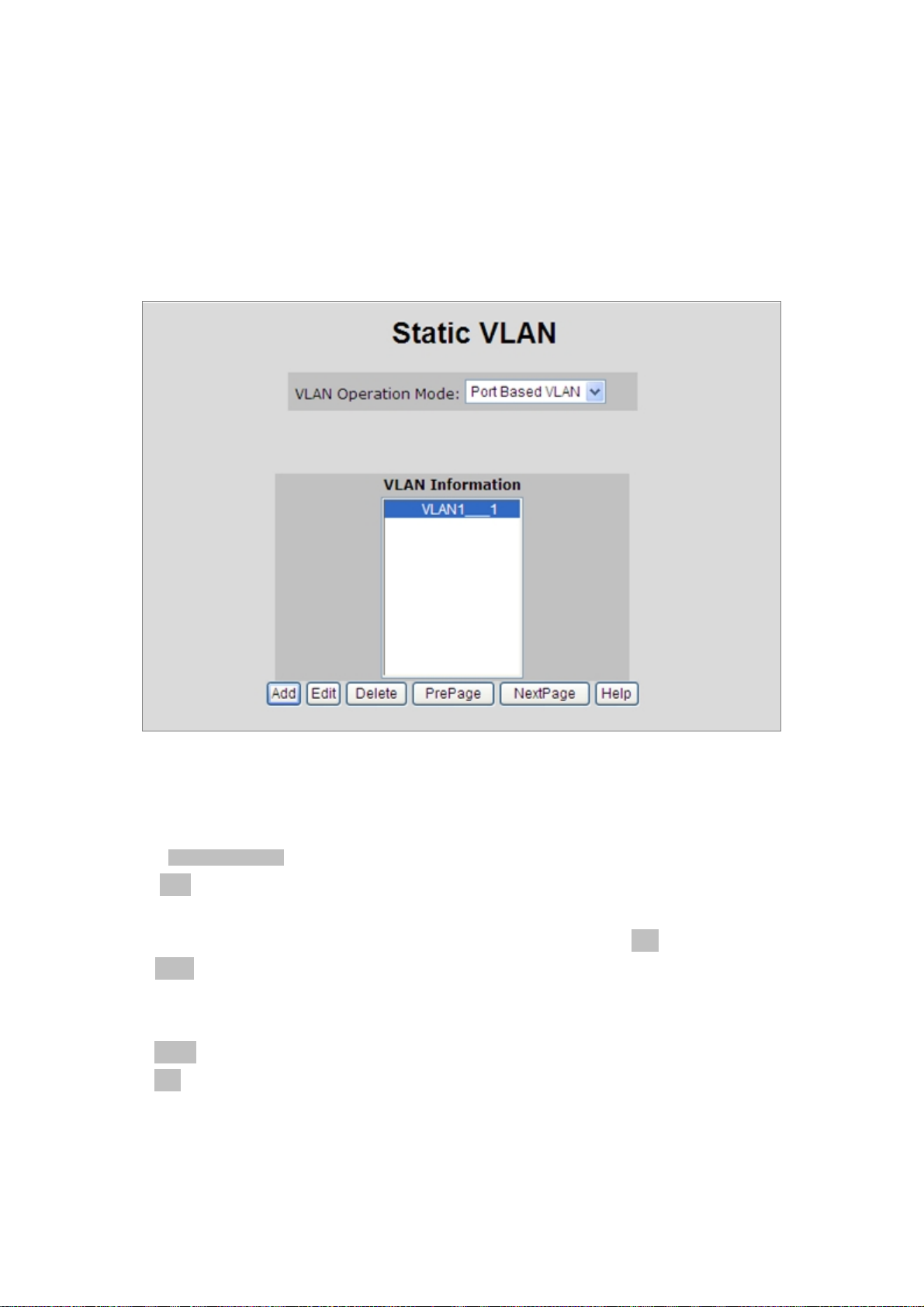
User’s Manual of VC-820M / VC-2400MR Series
4.4.3 Port-based VLAN
Packets can go among only members of the same VLAN group. Note all unselected ports are treated as belonging to
another single VLAN. If the port-based VLAN enabled, the VLAN-tagging is ignored.
In order for an end station to send packets to different VLANs, it itself has to be either capable of tagging packets it sends
with VLAN tags or attached to a VLAN-aware bridge that is capable of classifying and tagging the packet with different
VLAN ID based on not only default PVID but also other information about the packet, such as the protocol.
Figure 4-4-2: Port-based VLAN interface
Create a VLAN and add member ports to it
1. Click the hyperlink "VLAN” \ “Static VLAN" to enter the VLAN configuration interface.
2. Select “Port Based VLAN” at the VLAN Operation Mode, to enable the port-based VLAN function.
3. Click “Add “to create a new VLAN group. Then the following Fig ure 4-4-3 appears.
4. Type a name and Group ID for the new VLAN, the available range is 2-4094.
5. From the Available ports box, select ports to add to the Managed Switch and click “Add”.
6. Click Apply.
7. You will see the VLAN Group displays.
8. If the port-based VLAN groups list over one page, please click “Next Page” to view other VLAN groups on other page.
9. Use “Delete” button to delete unwanted port-based VLAN groups
10. Use “Edit” button to modify existing port-based VLAN groups.
By adding ports to the VLAN you have created one port-based VLAN group completely.
75
Page 76

User’s Manual of VC-820M / VC-2400MR Series
The page includes the following fields:
Object Description
Use this optional field to specify a name for the VLAN. It can be up to 16
VLAN Name
Group ID
Port
Member
alphanumeric characters long, including blanks.
You can configure the ID number of the VLAN by this item. This field is used to add
VLANs one at a time. The VLAN group ID and available range is 2-4094.
Indicate port 1 to port 10.
Add
Remove
Figure 4-4-3: Static VLAN interface
Defines the interface as a Port-Based member of a VLAN.
Forbidden ports are not included in the VLAN.
All unselected ports are treated as belonging to another single VLAN. If the port-based
VLAN enabled, the VLAN-tagging is ignored.
76
Page 77
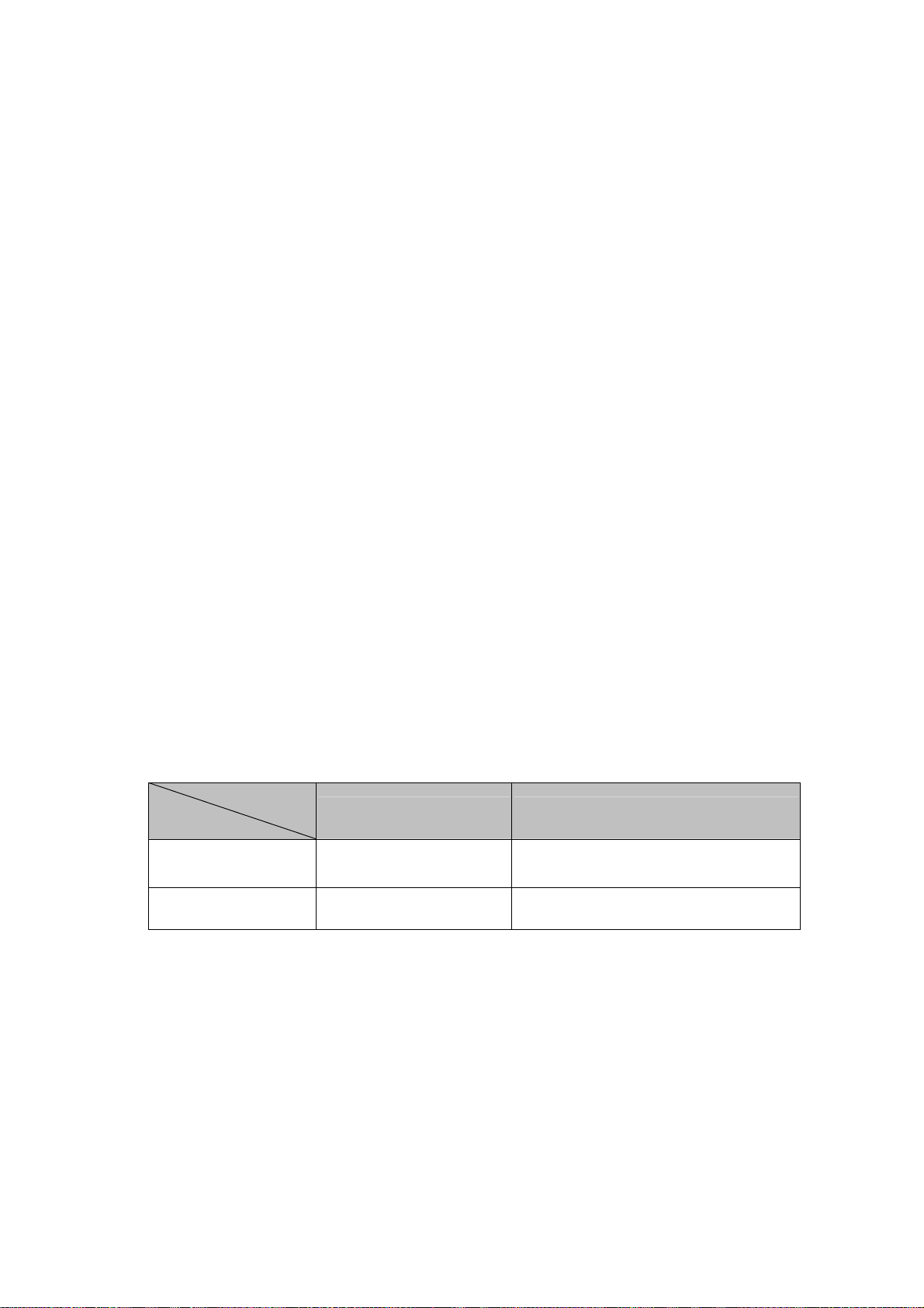
User’s Manual of VC-820M / VC-2400MR Series
4.4.4 802.1Q VLAN
Tagged-based VLAN is an IEEE 802.1Q specification standard. Therefore, it is possible to create a VLAN across devices
from different switch venders. IEEE 802.1Q VLAN uses a technique to insert a "tag" into the Ethernet frames. Tag contains
a VLAN Identifier (VID) that indicates the VLAN numbers.
You can create and delete Tag-based VLAN. There are 256 VLAN groups to provide configure. Enable 802.1Q VLAN, the
all ports on the switch belong to default VLAN, VID is 1. The default VLAN can't be deleting.
Understand nomenclature of the Switch
■ IEEE 802.1Q Tagged and Untagged
Every port on an 802.1Q compliant switch can be configured as tagged or untagged.
• Tagged
• Untgged
Frame Leave
Leave port is tagged Frame remains tagged Tag is inserted
Leave port is untagged Tag is removed Frame remain untagged
Ports with tagging enabled will put the VID number, priority and other VLAN information into the
header of all packets that flow into those ports. If a packet has previously been tagged, the port
will not alter the packet, thus keeping the VLAN information intact. The VLAN information in the
tag can then be used by other 802.1Q compliant devices on the network to make
packet-forwarding decisions.
Ports with untagging enabled will strip the 802.1Q tag from all packets that flow into those
ports. If the packet doesn't have an 802.1Q VLAN tag, the port will not alter the packet. Thus,
all packets received by and forwarded by an untagging port will have no 802.1Q VLAN
information. (Remember that the PVID is only used internally within the Switch). Untagging is
used to send packets from an 802.1Q-compliant network device to a non-compliant network
device.
Frame Income
Income Frame is tagged Income Frame is untagged
77
Page 78

4.4.4.1 VLAN Group Configuration
VLAN Group Configuration
User’s Manual of VC-820M / VC-2400MR Series
Figure 4-4-4: VLAN Group Configuration interface
1. Click the hyperlink "VLAN” \ “Static VLAN" to enter the VLAN configuration interface.
2. Select “802.1Q” at the VLAN Operation Mode, to enable the 802.1Q VLAN function.
3. Click Add to create a new VLAN group or Edit to management exist VLAN groups. Then the VLAN Group column
appears.
4. Input a VLAN group ID and available range is 2-4094.
78
Page 79

User’s Manual of VC-820M / VC-2400MR Series
Figure 4-4-5: VLAN Group Configuration interface
5. Select specific port as member port and the screen in Figure 4-4-6 appears.
6. After setup completed, please press “Apply” button to take effect.
7. Please press “Back” for return to VLAN configuration screen to add other VLAN group, the screen in Figure 4-33
appears.
8. If there are many groups that over the limit of one page, you can click Next to view other VLAN groups.
9. Use Delete button to delete unwanted VLAN.
10. Use Edit button to modify existing VLAN group.
79
Page 80

User’s Manual of VC-820M / VC-2400MR Series
Figure 4-4-6: 802.1Q VLAN Setting Web Page screen
The page includes the following fields:
Object Description
VLAN Name
VLAN ID
Port
UnTag Member
Use this optional field to specify a name for the VLAN. It can be up to 16
alphanumeric characters long, including blanks.
You can configure the ID number of the VLAN by this item. This field is used to
add VLANs one at a time.
The VLAN group ID and available range is 2-4094.
Indicate port 1 to port 10.
Untag
Tag
Packets forwarded by the interface are untagged.
Defines the interface as a tagged member of a VLAN. All packets
forwarded by the interface are tagged. The packets contain VLAN
information.
Enable 802.1Q VLAN, the all ports on the switch belong to default VLAN, VID is 1. The
default VLAN can't be deleted.
80
Page 81

User’s Manual of VC-820M / VC-2400MR Series
4.4.4.2 VLAN Filter
802.1Q VLAN Port Configuration
This page is used for configuring the Switch port VLAN. The VLAN per Port Configuration page contains fields for managing
ports that are part of a VLAN. The port default VLAN ID (PVID) is configured on the VLAN Port Configuration page. All
untagged packets arriving to the device are tagged by the ports PVID.
This section provides 802.1Q Ingress Filter of each port from the Switch, the screen in Figure 4-4-7 appears.
The page includes the following fields:
Object Description
NO
PVID
Indicate port 1 to port 10.
Set the port VLAN ID that will be assigned to untagged traffic on a given port.
This feature is useful for accommodating devices that you want to participate in
the VLAN but that don't support tagging.
The switch each port allows user to set one VLAN ID, the range is 1~255, default
Figure 4-4-7: 802.1Q Ingress filter interface
81
Page 82

User’s Manual of VC-820M / VC-2400MR Series
VLAN ID is 1.
The VLAN ID must as same as the VLAN ID that the port belong to VLAN group,
or the untagged traffic will be dropped.
Ingress Filtering 1
Ingress Filtering 2
Apply button
Ingress filtering lets frames belonging to a specific VLAN to be forwarded if the
port belongs to that VLAN.
Enable: Forward only packets with VID matching this port's configured VID.
Disable: Disable Ingress filter function.
Drop untagged frame.
Disable: Acceptable all Packet.
Enable: Only packet with match VLAN ID can be permission to go through the
port.
Press the button to save configurations.
4.4.5 Q-in-Q VLAN
■ IEEE 802.1Q Tunneling (Q-in-Q)
IEEE 802.1Q Tunneling (QinQ) is designed for service providers carrying traffic for multiple customers across their
networks. QinQ tunneling is used to maintain customer-specific VLAN and Layer 2 protocol configurations even when
different customers use the same internal VLAN IDs. This is accomplished by inserting Service Provider VLAN (SPVLAN)
tags into the customer’s frames when they enter the service provider’s network, and then stripping the tags when the
frames leave the network.
A service provider’s customers may have specific requirements for their internal VLAN IDs and number of VLANs supported.
VLAN ranges required by different customers in the same service-provider network might easily overlap, and traffic passing
through the infrastructure might be mixed. Assigning a unique range of VLAN IDs to each customer would restrict customer
configurations, require intensive processing of VLAN mapping tables, and could easily exceed the maximum VLAN limit of
4096.
82
Page 83

User’s Manual of VC-820M / VC-2400MR Series
The Managed Switch supports multiple VLAN tags and can therefore be used in MAN applications as a provider bridge,
aggregating traffic from numerous independent customer LANs into the MAN (Metro Access Network) space. One of the
purposes of the provider bridge is to recognize and use VLAN tags so that the VLANs in the MAN space can be used
independent of the customers’ VLANs. This is accomplished by adding a VLAN tag with a MAN-related VID for frames
entering the MAN. When leaving the MAN, the tag is stripped and the original VLAN tag with the customer-related VID is
again available.
This provides a tunneling mechanism to connect remote costumer VLANs through a common MAN space without
interfering with the VLAN tags. All tags use Ether Type 0x8100 or 0x88A8, where 0x8100 is used for customer tags and
0x88A8 are used for service provider tags.
In cases where a given service VLAN only has two member ports on the switch, the learning can be disabled for the
particular VLAN and can therefore rely on flooding as the forwarding mechanism between the two ports. This way, the MAC
table requirements is reduced.
4.4.5.1 Q-in-Q Port Setting
The QinQ VLAN \ QinQ Port Setting screen in Figure 4-4-8 appears.
The page includes the following fields:
Figure 4-4-8: Q-in-Q Port Setting interface
83
Page 84

Object Description
Enable: Sets the Managed Switch to QinQ mode, and allows the QinQ tunnel port to
QinQ
Disable:
The default is for the Managed Switch to function in Disable mode.
The Tag Protocol Identifier (TPID) specifies the ethertype of incoming packets on a
tunnel access port.
User’s Manual of VC-820M / VC-2400MR Series
be configured.
The Managed Switch operates in its normal VLAN mode.
QinQ TPID
Port QinQ
QinQ Uplink
• 802.1Q Tag: 8100
• vMAN Tag: 88A8
Default: 802.1Q Tag.
Check: Sets the Port to QinQ mode. Or the port operates in its normal VLAN mode.
Default: Un-check.
Check:
Cancel:
Configures IEEE 802.1Q tunneling (QinQ) for an uplink port to another device
within the service provider network.
Configures IEEE 802.1Q tunneling (QinQ) for a client access port to segregate
and preserve customer VLAN IDs for traffic crossing the service provider
network.
84
Page 85

User’s Manual of VC-820M / VC-2400MR Series
4.4.5.2 Q-in-Q Tunnel Setting
Business customers of service providers often have specific requirements for VLAN IDs and the number of VLANs to be
supported. The VLAN ranges required by different customers in the same service-provider network might overlap, and
traffic of customers through the infrastructure might be mixed. Assigning a unique range of VLAN IDs to each customer
would restrict customer configurations and could easily exceed the VLAN limit (4096) of the IEEE 802.1Q specification.
Using the QinQ feature, service providers can use a single VLAN to support customers who have multiple VLANs.
Customer VLAN IDs are preserved, and traffic from different customers is segregated within the service-provider network,
even when they appear to be in the same VLAN. Using QinQ expands VLAN space by using a VLAN-in-VLAN hierarchy
and retagging the tagged packets. A port configured to support QinQ is called a QinQ user-port. A port configured to support
QinQ Uplink is called a QinQ uplink-port.
Figure 4-4-9: Q-in-Q Tunnel Setting interface
To configure QinQ Port
1. Enable global QinQ function: select QinQ enable "Enable".
2. Fill QinQ Tpid.
3. Enable port QinQ function: select QinQ checkbox for special port.
4. Enable port QinQ Uplink function: select QinQ Uplink checkbox for special port.
85
Page 86

User’s Manual of VC-820M / VC-2400MR Series
4.4.6 GVRP VLAN
GVRP (GARP VLAN Registration Protocol or Generic VLAN Registration Protocol) is a protocol that facilitates control
of virtual local area networks (VLANs) within a larger network. GVRP conforms to the IEEE 802.1Q specification, which
defines a method of tagging frames with VLAN configuration data. This allows network devices to dynamically exchange
VLAN configuration information with other devices.
86
Page 87

User’s Manual of VC-820M / VC-2400MR Series
4.4.6.1 GVRP Setting
To configure GVRP
Enable global GVRP function: select GVRP enable "Enable".
Enable port GVRP function: select GVRP checkbox for special port.
Figure 4-4-10: GVRP Configuration Web interface
The page includes the following fields:
Object Description
GVRP
Port
Port GVRP
Enable global GVRP function
Indicate port 1 to port 10.
Enable selected port GVRP function
87
Page 88

User’s Manual of VC-820M / VC-2400MR Series
4.4.6.2 GVRP Table
The GVRP Table can be used to display dynamic VLANs from being learned via GVRP.
The page includes the following fields:
Object Description
VLAN ID
Port Members
Display the learned VLANs via GVRP protocol on GVRP enabled ports.
The Managed Switch allows displaying up to 128 dynamic VLAN entries.
Identify the GVRP enabled port that dynamic VLAN is learned from.
Figure 4-4-11: GVRP Table Web interface
88
Page 89

User’s Manual of VC-820M / VC-2400MR Series
4.5 Trunking
Port Trunking (also called “Link Aggregation”) is the combination of several ports or network cables to expand the
connection speed beyond the limits of any one single port or network cable. The Managed Switch supports two types of port
trunk technology:
Static Trunk
LACP
The Link Aggregation Control Protocol (LACP) provides a standardized means for exchanging information between
Partner Systems on a link to allow their Link Aggregation Control instances to reach agreement on the identity of the Link
Aggregation Group to which the link belongs, move the link to that Link Aggregation Group, and enable its transmission and
reception functions in an orderly manner. Link aggregation lets you group up to eight consecutive ports into a single
dedicated connection. This feature can expand bandwidth to a device on the network. LACP operation requires
Full-duplex mode, more detail information refers to IEEE 802.3ad.
4.5.1 Aggregator setting
This section provides Port Trunk-Aggregator Setting of each port from the Managed Switch, the screen in Figure 4-6-1
appears.
Figure 4-5-1: Port Trunk—Aggregator setting interface (two ports are added to the left field with LACP enabled)
The page includes the following fields:
89
Page 90

Object Description
A value which is used to identify the active LACP. The Managed Switch with the
System Priority:
lowest value has the highest priority and is selected as the active LACP peer of
the trunk group.
User’s Manual of VC-820M / VC-2400MR Series
Group ID:
LACP:
Work ports:
There are 13 trunk groups to be selected. Assign the "Group ID" to the trunk
group.
Enabled, the trunk group is using LACP. A port which joins an LACP trunk
group has to make an agreement with its member ports first.
Disabled, the trunk group is a static trunk group. The advantage of having
the LACP disabled is that a port joins the trunk group without any
handshaking with its member ports; but member ports won’t know that they
should be aggregated together to form a logic trunk group.
This column field allows the user to type in the total number of active port up to
four. With LACP static trunk group, e.g. you assign four ports to be the
members of a trunk group whose work ports column field is set as two; the
exceed ports are standby/redundant ports and can be aggregated if working
ports fail. If it is a static trunk group (non-LACP), the number of work ports must
equal the total number of group member ports.
Please notice that a trunk group, including member ports split between two switches, has to enable the
LACP function of the two switches.
4.5.2 Aggregator Information
When you had setup the LACP aggregator, you will see relation information in here.
LACP disabled
Having set up the aggregator setting with LACP disabled, you will see the local static trunk group information on the tab of
Aggregator Information.
90
Page 91

User’s Manual of VC-820M / VC-2400MR Series
Figure 4-5-2: Assigning 2 ports to a trunk group with LACP disabled
The page includes the following fields:
Figure 4-5-3: Static Trunking Group information
Object Description
Group Key:
Port Member:
This is a read-only column field that displays the trunk group ID.
This is a read-only column field that displays the members of this static trunk
group.
91
Page 92

User’s Manual of VC-820M / VC-2400MR Series
LACP enabled
Having set up the aggregator setting with LACP enabled, you will see the trunking group information between two switches
on the tab of Aggregator Information.
Switch 1 configuration
1. Set System Priority of the trunk group. The default is 32768.
2. Select a trunk group ID by pull down the drop-down menu bar.
3. Enable LACP.
4. Include the member ports by clicking the Add button after selecting the port number and the column field of
Work Ports changes automatically.
Figure 4-5-4: Aggregation Information of Switch 1
5. Click on the tab of Aggregator Information to check the trunked group information as the illustration shown
above after the two switches configured.
Switch 2 configuration
6. Set System Priority of the trunk group. For example: 1.
7. Select a trunk group ID by pull down the drop-down menu bar.
8. Enable LACP.
9. Include the member ports by clicking the Add button after selecting the port number and the column field of
Work Ports changes automatically.
92
Page 93
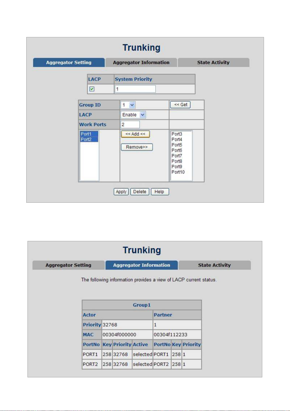
User’s Manual of VC-820M / VC-2400MR Series
Figure 4-5-5: Swit ch 2 configuration interface
10. Click on the tab of Aggregator Information to check the trunked group information as the illustration shown
above after the two switches configured.
Figure 4-5-6: Switch 1 Aggregator Information
93
Page 94

User’s Manual of VC-820M / VC-2400MR Series
4.5.3 State Activity
Having set up the LACP aggregator on the tab of Aggregator Setting, you can configure the state activity for the members of
the LACP trunk group. You can tick or cancel the checkbox beside the state label. When you remove the tick mark of the
port and click
Apply
, the port state activity will change to
Figure 4-5-7: State Activity of Switch 1
Passive
.
The page includes the following fields:
Object Description
Active: The port automatically sends LACP protocol packets.
Passive:
A link having two passive LACP nodes will not perform dynamic LACP trunk because both
ports are waiting for an LACP protocol packet from the opposite device.
The port does not automatically send LACP protocol packets, and responds only
if it receives LACP protocol packets from the opposite device.
94
Page 95

User’s Manual of VC-820M / VC-2400MR Series
4.6 Forwarding and Filtering
The frames of Ethernet Packets contain a MAC address (SMAC address), which shows the MAC address of the equipment
sending the frame. The SMAC address is used by the switch to automatically update the MAC table with these dynamic
MAC addresses. Dynamic entries are removed from the MAC table if no frames with the corresponding SMAC address
have been seen after a configurable age time.
4.6.1 Dynamic MAC Table
Entries in the MAC Table are shown on this page. The Dynamic MAC Table contains up to 8192 entries, and is sorted first
by VLAN ID, then by MAC address. You can view all of the dynamic MAC addresses learned by the listed port.
MAC Table Columns
Object Description
• NO
• MAC
• PORT
• VID
• Type
Click “
to clear the dynamic MAC addresses information of the current port shown on the screen.
Clear”
Figure 4-6-1: Dynamic MAC Address interface
The MAC address index entry.
The MAC address of the entry.
The ports that are members of the entry.
The VLAN ID of the entry.
Indicates whether the entry is a static or dynamic entry.
95
Page 96

User’s Manual of VC-820M / VC-2400MR Series
4.6.2 Static MAC Table
You can add a static MAC address that remains in the switch's address table regardless of whether the device is physically
connected to the switch. This saves the switch from having to re-learn a device's MAC address when the disconnected or
powered-off device is active on the network again. Via this interface, you can add / delete a static MAC address.
Add the Static MAC Address
You can add static MAC address in the switch MAC table here.
The page includes the following fields:
Object Description
MAC Address:
Figure 4-6-2: Static MAC Addresses interface
Enter the MAC address of the port that should permanently forward traffic,
regardless of the device network activity.
Port num.:
VLAN ID:
Pull down the selection menu to select the port number.
The VLAN ID for the entry.
96
Page 97

User’s Manual of VC-820M / VC-2400MR Series
4.6.3 MAC Filtering
By filtering MAC address, the switch can easily filter the pre-configured MAC address and reduce the un-safety. You can
add and delete filtering MAC address.
The page includes the following fields:
Object Description
MAC Address:
VLAN ID:
Figure 4-6-3: MAC Filtering interface
Enter the MAC address that you want to filter.
The VLAN ID for the entry.
97
Page 98

User’s Manual of VC-820M / VC-2400MR Series
4.7 IGMP Snooping
4.7.1 Theory
The Internet Group Management Protocol (IGMP) lets host and routers share information about multicast groups
memberships. IGMP snooping is a switch feature that monitors the exchange of IGMP messages and copies them to the
CPU for feature processing. The overall purpose of IGMP Snooping is to limit the forwarding of multicast frames to only
ports that are a member of the multicast group.
About the Internet Group Management Protocol (IGMP) Snooping
Computers and network devices that want to receive multicast transmissions need to inform nearby routers that they will
become members of a multicast group. The Internet Group Management Protocol (IGMP) is used to communicate this
information. IGMP is also used to periodically check the multicast group for members that are no longer active. In the case
where there is more than one multicast router on a sub network, one router is elected as the ‘queried’. This router then
keeps track of the membership of the multicast groups that have active members. The information received from IGMP is
then used to determine if multicast packets should be forwarded to a given sub network or not. The router can check, using
IGMP, to see if there is at least one member of a multicast group on a given subnet work. If there are no members on a sub
network, packets will not be forwarded to that sub network.
Figure 4-7-1: Multicast Service
98
Page 99

User’s Manual of VC-820M / VC-2400MR Series
Figure 4-7-2: Multicast flooding
Figure 4-7-3: IGMP Snooping multicast stream control
99
Page 100

User’s Manual of VC-820M / VC-2400MR Series
IGMP Versions 1 and 2
Multicast groups allow members to join or leave at any time. IGMP provides the method for members and multicast routers
to communicate when joining or leaving a multicast group.
IGMP version 1 is defined in RFC 1112. It has a fixed packet size and no optional data.
The format of an IGMP packet is shown below:
IGMP Message Format
Octets
0 8 16 31
Type Response Time Checksum
Group Address (all zeros if this is a query).
The IGMP Type codes are shown below:
Type Meaning
0x11
0x11
0x16 Membership Report (version 2).
0x17 Leave a Group (version 2).
0x12 Membership Report (version 1).
IGMP packets enable multicast routers to keep track of the membership of multicast groups, on their respective sub
networks. The following outlines what is communicated between a multicast router and a multicast group member using
IGMP.
A host sends an IGMP “report” to join a group.
Membership Query (if Group Address is 0.0.0.0).
Specific Group Membership Query (if Group Address is
Present).
A host will never send a report when it wants to leave a group (for version 1).
A host will send a “leave” report when it wants to leave a group (for version 2).
Multicast routers send IGMP queries (to the all-hosts group address: 224.0.0.1) periodically to see whether any group
members exist on their sub networks. If there is no response from a particular group, the router assumes that there are no
group members on the network.
The Time-to-Live (TTL) field of query messages is set to 1 so that the queries will not be forwarded to other sub networks.
IGMP version 2 introduces some enhancements such as a method to elect a multicast queried for each LAN, an explicit
leave message, and query messages that are specific to a given group.
100
 Loading...