

Page 1

Gigabit Ethernet over VDSL2
Converter/Bridge
VC-231G/VC-234G
User’s Manual
Page 2

Trademarks
Copyright © PLANET Technology Corp. 2017.
Contents are subject to revision without prior notice.
PLANET is a registered trademark of PLANET Technology Corp.
All other trademarks belong to their respective owners.
Disclaimer
PLANET Technology does not warrant that the hardware will
work properly in all environments and applications, and makes
no warranty and representation, either implied or expressed,
with respect to the quality, performance, merchantability, or
tness for a particular purpose.
PLANET has made every effort to ensure that this User’s Manual
is accurate; PLANET disclaims liability for any inaccuracies or
omissions that may have occurred.
Information in this User’s Manual is subject to change without
notice and does not represent a commitment on the part of
PLANET. PLANET assumes no responsibility for any inaccuracies
that may be contained in this User’s Manual. PLANET makes no
commitment to update or keep current the information in this
User’s Manual, and reserves the right to make improvements
to this User’s Manual and/or to the products described in this
User’s Manual, at any time without notice.
If you nd information in this manual that is incorrect,
misleading, or incomplete, we would appreciate your comments
and suggestions.
FCC Warning
This equipment has been tested and found to comply with
the limits for a Class B digital device, pursuant to Part 15
of the FCC Rules. These limits are designed to provide
reasonable protection against harmful interference when the
equipment is operated in a commercial environment. This
equipment generates, uses, and can radiate radio frequency
energy and, if not installed and used in accordance with the
Instruction manual, may cause harmful interference to radio
Page 3
communications. Operation of this equipment in a residential
area is likely to cause harmful interference in which case the
user will be required to correct the interference at his own
expense.
CE Mark Warning
This is a Class A product. In a domestic environment, this
product may cause radio interference, in which case the user
may be required to take adequate measures.
Energy Saving Note of the Device
This power required device does not support Standby mode
operation.
For energy saving, please remove the power cable to disconnect
the device from the power circuit.
Without removing power cable, the device will still consume
power from the power source. In view of Saving the Energy
and reducing the unnecessary power consumption, it is strongly
suggested to remove the power connection for the device if this
device is not intended to be active.
WEEE Warning
To avoid the potential effects on the environment and
human health as a result of the presence of hazardous
substances in electrical and electronic equipment, end
users of electrical and electronic equipment should
understand the meaning of the crossed-out wheeled bin symbol.
Do not dispose of WEEE as unsorted municipal waste and have
to collect such WEEE separately.
Revision
PLANET Gigabit Ethernet over VDSL2 Converter/Bridge User’s
Manual
For Models: VC-231G, VC-234G
Revision: 1.0 (June 2017)
Part No.: 2350-AC0500-000
Page 4

Table of Contents
1. Package Contents .............................................................. 5
2. Product Features ............................................................... 6
3. Hardware Introduction ....................................................... 8
3.1 Front Panel and LED Indicators .................................... 8
3.2 Rear Panel and Mode DIP Switch ................................11
3.3 Power Information .....................................................15
4. Connecting And Using The VDSL2 Bridge ...........................16
4.1 Point-to-Point Application--LAN to LAN Connection ........18
4.2 Point-to-Multipoint Application--Connect to IP DSLAM....19
5. Product Specications .......................................................22
6. Performace Table ..............................................................24
7. Troubleshooting ................................................................26
8. FAQ .............................................................................27
9. Customer Support ............................................................29
Appendix: Wall-mount and Chassis Installation .......................30
Page 5
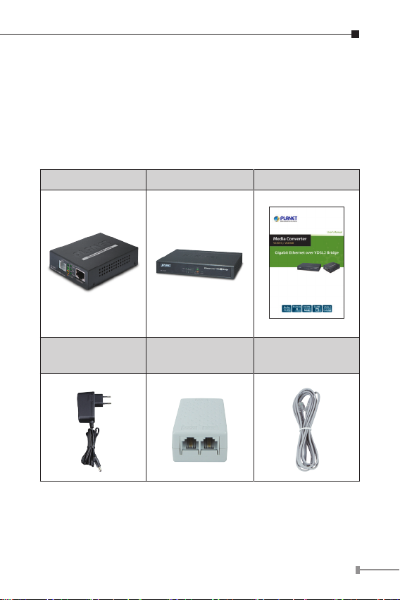
1. Package Contents
Thank you for purchasing PLANET Gigabit Ethernet over VDSL
Converter/Bridge, VC-231G/VC-234G. In the following section,
the term “VDSL2 Bridge” means the VC-231G or VC-234G.
Open the box of the VDSL2 Bridge and carefully unpack it. The
box should contain the following items:
VC-231G VC-234G User’s Manual x 1
5V, 2A Power
Adapter x 1
If any of these are missing or damaged, please contact your
dealer immediately; if possible, retain the carton including the
original packing material, and use them again to repack the
product in case there is a need to return it to us for repair.
Splitter x 1
(VC-231G only)
RJ11 Telephone
Wire x 1
55
Page 6

2. Product Features
Physical
VC-231G
¾ 1 10/100/1000BASE-T RJ45 auto-MDI/MDI-X ports
¾ 1 RJ11, built-in splitters for POTS connection
¾ Additional splitter for POTS connection
VC-234G
¾ 4 10/100/1000BASE-T RJ45 auto-MDI/MDI-X ports
¾ 1 RJ11, built-in splitters for POTS connection
¾ 1 VDSL2 RJ11 female phone jack
Product Features
¾ Cost-effective bridge function to connect two Ethernet LANs
¾ Point-to-multipoint application: Compatible with PLANET
and third-party VDSL2 IP DSLAM for last mile soltuion
¾ Point-to-point application: LAN to LAN extension over phone
wire
¾ Up to 200/160Mbps bandwidth (in G.INP, Sym, 8dB mode)
¾ ITU-T G.993.2 VDSL2 standard
¾ ITU-T G.993.5 G.vectoring and G.INP
¾ DMT-based coding technology
¾ POST splitter to share voice and date
¾ CO/CPE mode selectable via DIP switch
¾ Selectable target band plan (symmetric and asymmetric)
and SNR margin
¾ Half duplex back pressure and IEEE 802.3x full duplex
pause frame ow control
¾ One RJ11 connector for VDSL port with VDSL connection
6
Page 7

¾ Voice and data communication can be shared simultane-
ously based on the existing telephone wire with distance up
to 1.4km
¾ Supports a packet size of up to 9K bytes; IEEE 802.1Q
VLAN tag transparency
¾ VDSL2 stand-alone transceiver for simple bridge modem
application
¾ Advantage of minimum installation time (Simply by Plug
and Play)
¾ Supports extensive LED indicators for network diagnosis
Hardware Features
¾ Compact size, wall-mountable design
¾ Metal case, good for heat sinking
¾ Easy installation; ideal solution for space-limited locations
¾ Co-work with PLANET MC family Media Chassis (MC-700/
MC-1500/MC-1500R/MC-1500R48)
7
Page 8
3. Hardware Introduction
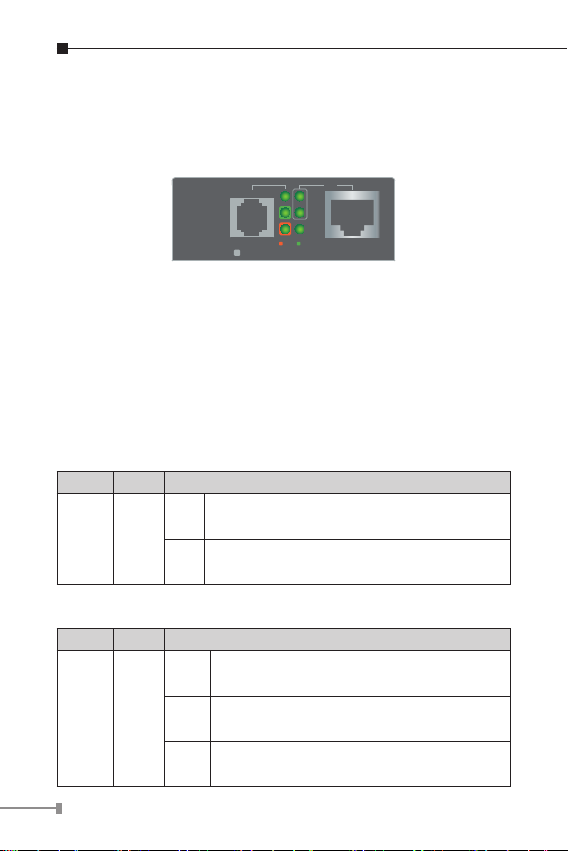
3.1 Front Panel and LED Indicators
VC-231G Front Panel
VDSL
VC-231G
Ethernet over VDSL 2 Converter
Figure 3-1-1: VC-231G Front Panel
¾ 10/100/1000BASE-T RJ45 connector for Ethernet
¾ RJ11 connector for VDSL2; connect to IP DSLAM or another
VDSL2 Bridge
¾ LEDs for power, Ethernet and VDSL
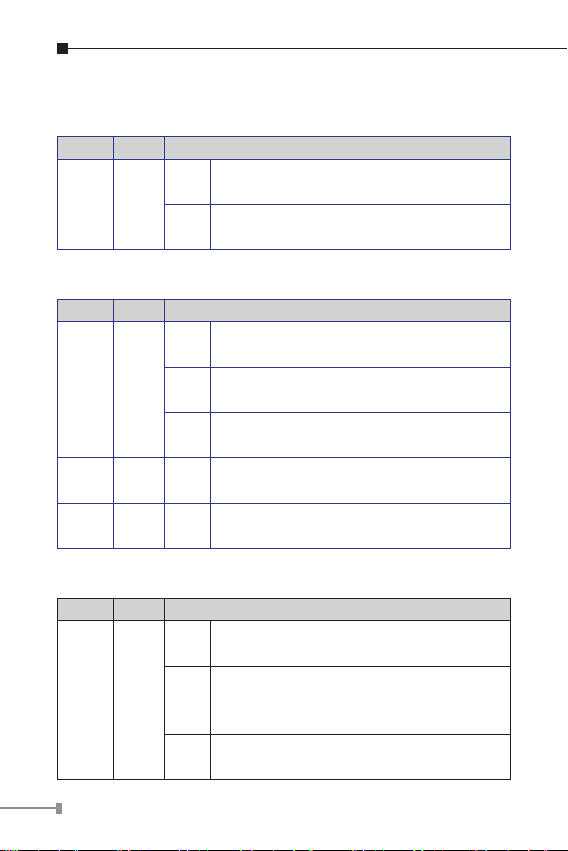
VC-231G LED Indicators
System
LED Color Function
Indicates that the VDSL2 Bridge has
Lit
PWR Green
power.
Indicates that the VDSL2 Bridge has no
Off
power.
VDSL
LED Color Function
Indicates that the VDSL link is
Lit
established.
Fast
VDSL Green
Indicates that the VDSL link is at training
Blink
status (about 10 seconds).
Slow
Indicates that the VDSL link is at idle
Blink
status.
8
TP
1000
100
PWR
10/100/1000
CO
CPE
Page 9
CO Green Lit
CPE Green Lit
Indicates the VDSL2 Bridge is running in
CO mode.
Indicates the VDSL2 Bridge is running in
CPE mode.
100/1000BASE-T Port
LED Color Function
Indicates that the port is operating at
Lit
1000Mbps.
Indicates that the VDSL2 Bridge is
1000 Green
Blink
actively sending or receiving data over
that port at 1000Mbps.
Indicates that the port is link down or
Off
1000Mbps.
Indicates that the port is operating at
Lit
100Mbps or 10Mbps.
Indicates that the VDSL2 Bridge is
100 Green
Blink
actively sending or receiving data over
that port at 100Mbps or 10Mbps.
Indicates that the port is link down or
Off
10Mbps.
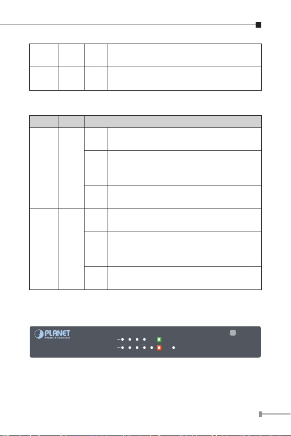
Front Panel - VC-234G
1000
LNK/ACT
VC-234G
10/100
1
2 3 4 VDSL CPE
Figure 3-1-2: VC-234G Front Panel
¾ LEDs for power, Ethernet and VDSL
Ethernet over VDSL Bridge
CO
Power
2
9
Page 10
LED Indicators – VC-234G
System
LED Color Function
Indicates that the VDSL2 Bridge has
Lit
PWR Green
VDSL
LED Color Function
VDSL Green
CO Green Lit
CPE Green Lit
100/1000BASE-T Port
LED Color Function
1000 Green
power.
Indicates that the VDSL2 Bridge has no
Off
power.
Indicates that the VDSL link is
Lit
established.
Fast
Indicates that the VDSL link is at training
Blink
status (about 10 seconds).
Slow
Indicates that the VDSL link is at idle
Blink
status.
Indicates the VDSL2 Bridge is running in
CO mode.
Indicates the VDSL2 Bridge is running in
CPE mode.
Indicates that the port is operating at
Lit
1000Mbps.
Indicates that the VDSL2 Bridge is
Blink
actively sending or receiving data over
that port at 1000Mbps.
Indicates that the port is link down or
Off
1000Mbps.
10
Page 11

Indicates that the port is operating at
Lit
100Mbps or 10Mbps.
Indicates that the VDSL2 Bridge is
100 Green
Blink
actively sending or receiving data over
that port at 100Mbps or 10Mbps.
Indicates that the port is link down or
Off
10Mbps.
3.2 Rear Panel and Mode DIP Switch
VC-231G Rear Panel
5V DC
Mode Tran.
Band SNR
CO
Asym.
G.INP
CPE
Interleave 8dB
Sym.
Figure 3-2-1: VC-231G Rear Panel
¾ DIP switch
¾ DC jack (DC input) for power adapter
VC-234G Rear Panel
12dB
Asym.
G.INP
5V DC
CO
OFF
1 2 3 4
ON
ON
8dB
Sym.
Inter
CPE
VDSLPhone
OFF
12dB
1
2 3
4
ON
ON
LAN
4 3 2 1
10/100/1000T
Figure 3-2-2: VC-234G Rear Panel
¾ Four 10/100/1000BASE-T RJ45 connectors for Ethernet
¾ One RJ11 connector for VDSL2; connect to IP DSLAM or
another VDSL2 Bridge
11
Page 12

¾ One RJ11 connector for telephone or PBX POTS
¾ DIP switch
¾ DC jack (DC input) for power adapter
DC Power Jack
The VC-234G/VC-231G requires 5V DC, 2A power input,
which conforms to the bundled AC adapter. Should you have
the issue of power connection, please contact your local sales
representative.
The device is a power-required device, meaning it
will not work till it is powered. If your networks
should be active all the time, please consider
Note
Note
using UPS (uninterrupted power supply) for your
device. It will prevent you from network data loss
or network downtime.
In some areas, installing a surge suppression
device may also help to protect your Ethernet
over VDSL2 Bridge from being damaged by
unregulated surge or current to the Ethernet over
VDSL2 Bridge or the power adapter.
DIP Switch
The Ethernet over VDSL2 Bridge provides 4 selective
transmission modes. By switching the transmission modes,
you can obtain a best transmission mode to suit with phone
line quality or distance of connectivity. The following is the
summary table of transmission setting, bandwidth and distance
extensibility tested for AWG 24 (0.5mm) twisted-pair without
noise and cross talk.
12
Page 13

DIP-1 DIP-2 DIP-3 DIP-4
Mode Transmission Band Prole SNR Margin
OFF CO G.INP Asymmetric 12dB
ON (default) CPE Interleave Symmetric 8dB
DIP-1: Mode (CO/CPE)
CO
(Central
Ofce)
CPE
(Customer
Premises
Equipment)
Note
DIP-2: Transmission (G. INP and Interleave mode)
G. INP
Interleave
The Master device mode, usually the CO
device, is located at the data center of ISP or
enterprise to link to the backbone.
The Slave device mode, usually the CPE
device, is located at branch ofce, home or
remote side as the long reach data receiver.
The CPE can be connected to the PC, IP
camera or wireless access point or other
network devices.
When the VDSL2 Bridge operates in CPE mode,
DIP switches 2, 3, and 4 are without function.
Method of protection against bursts from other
devices or lines to impact your xDSL line.
Method of error correction used on xDSL
line. Interleave requires additional latency to
improve resilience to burst of error.
13
Page 14

DIP-3: Band Prole (Asymmetric/Symmetric)
Asymmetric mode provides more bandwidth
Asymmetric
Symmetric
DIP-4: SNR (Signal Noise Ratio) Margin
When the SNR margin is selected, the system provides
12dB/8dB SNR margin for across all usable loop lengths. Better
channel noise protection is made with the higher SNR margin.
Note
Note
than the other side.
This mode provides the highest bandwidth in
short range.
With G.997 band plan supported, symmetric
mode can provide almost the same rate of
downstream and upstream.
By default, the four DIP switches, set at the
“ON” position, are operated as “CPE”. For operating as “CO”, please turn DIP 1 switch to the
“OFF” position. Then adjust other DIP switches
accordingly to fulfill different network application
demands.
Please power off the VDSL2 Bridge before
making any transmission mode adjustment.
14
Page 15

3.3 Power Information
The power jack of VC-231G and VC-234G measures 2.5mm in
the central post and requires +5VDC power input. It conforms
to the bundled AC-DC adapter and Planet’s Media Chassis.
Should you have the issue of power connection, please contact
your local sales representative.
Please keep the AC-DC adapter as a spare part when your
VC-231G is installed to a Media Chassis.
2.5mm
DC Receptacle 2.5mm
+5V for each slot
DC receptacle is 2.5mm wide that conforms to and
matches the VDSL2 Converter 2.5mm DC jack’s central
post. Do not install any improper unit, model of the VDSL2
Bridge.
15
Page 16

4. Connecting And Using The VDSL2 Bridge
The Ethernet to VDSL2 Bridge does not require any software
conguration. Users can immediately use any feature of this
product simply by attached the cables and plug power on. There
is some key limitation on the VDSL2 Bridge. Please check the
following items:
¾ The device can be used for Point-to-Point (one CO device
to one CPE device) connection or Point-to-Multipoint (one
multi-port CO device to multi CPE devices) and allows data
and voice work on the same telephone lines.
¾ The VC-231G provides only one RJ11 connector for VDSL2
port to build VDSL2 connection. For voice device connection,
there is an additional splitter from VC-231G packages is an
idea choice.
¾ The VC-234G provides two RJ11 connectors for VDSL2 port.
One for voice device connection (like telephone) and the
other one for VDSL2 network link connection.
¾ Depending on the quality of telephone line, the maximum
distance of one VDSL2 segment is 1.4km (4593ft) with AWG
24 telephone wires. The distance could vary on the quality of
telephone wires.
16
Page 17

Splitter
Telephone wire
Telephone wire
VC-231G
Ethernet over VDSL 2 Converter
RJ45 Cat.5
Twisted-pair Cable
RJ11 Line Cord
RJ11 Line Cord
TP
VDSL
1000
100
PWR
10/100/1000
CO
CPE
Phone
RJ11 Phone Jack
VC-231G
Switch
IP Camera IP TV Wireless
PC
Phone
VDSLPhone
VC-234G
LAN
4 3 2 1
IP Camera
12dB
Asym.
G.INP
5V DC
CO
OFF
1 2 3 4
ON
ON
8dB
Sym.
Inter
CPE
IP TV Wireless LaptopPC
Laptop
1000BASE-T UTP
RJ11 Phone Jack
10/100/1000T
1000BASE-T UTP
17
Page 18

4.1 Point-to-Point Application -- LAN to LAN
CO
G.INP
Asym.
Sym.
8dB
ON
OFF
1 2 3 4
ON
CO
G.INP
Asym.
Sym.
8dB
ON
OFF
1 2 3 4
ON
Connection
Two sets of the VDSL2 Bridge could be used to link two local
Area networks that are located in a different place. Through
the normal telephone line, it could be set up a 190/190Mbps
(VC-234G, G.INP, sym) symmetric backbone, but one VDSL2
Bridge must be Master (CO mode) and the other one is Slave
(CPE mode).
LAN to LAN Connection
Ethernet Telephone Network
Main office/PBX,
Telco CO,
Wire Closet
Telephone wire
Phone
Ethernet over VDSL2 and Telephone Network
Telephone wire
Main office/PBX,
Telco CO,
Wire Closet
18
VC-234G/CO
VDSL2
Up to 1.4km
VC-234G/CPE
VDSL2
Phone
1000BASE-T UTP
Telephone wire
VDSL2
Page 19

Refer to the following procedures to set up the VC-234G/
VC-231G LAN to LAN connection.
1. [LAN1] Set the VC-234G/VC-231G at LAN 1 to be CO mode
from the DIP switch.
2. [LAN2] Set the VC-234G/VC-231G at LAN 2 to be CPE mode
from the DIP switch.
3. Power on the VC-234G/VC-231G CO and CPE at both sides by
connecting its power source.
4. Power LED will illuminate.
5. Connect VDSL line from another VDSL device to RJ11 VDSL
port of the VC-234G/VC-231G.
6. VDSL LNK LED will blink to illuminate at both VDSL2
bridges.
7. Connect telephone to the RJ11 Phone port of the VC-234G/
VC-231G.
8. Connect VC-234G/VC-231G Ethernet LAN port to other
network device via regular Cat.5 UTP cable.
4.2 Point-to-Multipoint Application -- Connect to IP
DSLAM
To build a local Internet in apartments, hotels and campuses
and hospitality environments, it requires:
The multi-port VDSL2 IP DSLAM or VDSL2 switch (for example,
PLAMET VDL-2420M and VC-820M) operates as a CO Master
and needs to be placed in the wiring center (MDF room) and
connect to the telephone line system.
On the other hand, it needs to install one or many CPE Slaves
(VC-231G or VC-234G VDSL Bridge) on the individual client side
and connect to the multi-port Master through the telephone
lines.
19
Page 20

Multi-LAN Connection
Ethernet Telephone Network
Main office/PBX,
Telco CO,
Wire Closet
Telephone wire
Telephone wire
Phone
Phone
Ethernet over VDSL2 and Telephone Network
Splitter
VDSL2
Phone
Switch
VC-231G
VC-234G
Phone
Telephone wire
VDSL2
VDSL2
Main office/PBX,
Telco CO,
Wire Closet
VDSL2 Switch
(Multi-port CO)
UP to 1.4km
VDSL2
Telephone wire
100BASE-TX UTP
1000BASE-T UTP
Refer to the following procedure to set up the VC-234G/
VC-231G to IP DSLAM connection.
1. [Remote End] Set the remote IP DSLAM/VDSL2 switch to
CO mode with proper VDSL2 prole.
2. [Local End] Set the VC-234G/VC-231G at the local end to
CPE mode from the DIP switch
3. Power on the VC-234G/VC-231G CPEs by connecting its
power source.
20
Page 21

4. Power LED will illuminate.
5. Connect VDSL line from IP DSLAM/VDSL2 switch to RJ11
VDSL port of the VC-234G/VC-231G.
6. VDSL LNK LED will blink to illuminate.
7. Connect telephone to the RJ11 Phone port of the VC-234G/
VC-231G.
8. Connect VC-234G/VC-231G Ethernet LAN port to other
network device via regular Cat.5 UTP cable.
When deciding where to put the converter and / or prolong the
operational life of the bridge, please also refer to the following
points:
¾ It is accessible and cables can be connected easily.
¾ Cabling is away from sources of electrical noise such as
radios, transmitters, motors, power lines and uorescent
lighting xtures.
¾ Do not place objects on top of any unit or stack
¾ Water or moisture cannot enter the VDSL2 Bridge.
¾ Air owing around the unit and through the vents in the side
of the case is not restricted (We recommend that you provide
a minimum of 25mm clearance).
21
Page 22

5.ProductSpecications
Product VC-231G VC-234G
Hardware Specications
1 10/100/1000BASE-T
LAN Ports
VDSL Port
Phone Port
Dimensions
(W x D x H)
Weight 184g 350g
Power
Requirement
LED Indicators
Housing Metal
DIP Switch &
Functionality
RJ45 auto-MDI/MDI-X
ports
1 VDSL2 RJ11 female phone jack
Twisted-pair telephone wires (AWG24 or better)
up to 1.4km
Additional splitter for
POTS connection
97 x 70 x 26 mm
DC 5V, 2A external power
Power: Green
1000BASE-T LNK/ACT: Green
100BASE-T LNK/ACK: Green
VDSL: Green
CO: Green
CPE: Green
4-position DIP switch
CO/CPE mode select
Selectable G.INP and interleaved mode
Selectable target Band plan
Selectable target SNR mode
4 10/100/1000BASE-T
RJ45 auto-MDI/MDI-X
ports
1 RJ11, built-in splitters
for POTS connection
154.6 x 86.0 x 26.3
mm
22
Page 23

Switch Specications
Switch Processing
Scheme
Address Table 2K entries
Flow Control
Jumbo Packet Size 9K bytes
System Specications
VDSL Compliance
ADSL Compliance
Standards Conformance
Standards
Compliance
Store-and-Forward
Back pressure for half duplex
IEEE 802.3x pause frame for full duplex
VDSL-DMT
¾ ITU-T G.993.1 VDSL
¾ ITU-T G.997.1
¾ ITU-T G.993.2 VDSL2
(Prole 17a/30a Support)
¾ ITU-T G.993.5 G. Vectoring
¾ ITU-T G.998
¾ G.INP
Capable of ADSL2/2+ standard
¾ ITU G.992.3 G.dmt.bis
¾ ITU G.992.5 G.dmt.bisplus
Data Rate: Up to 24Mbps
IEEE 802.3 Ethernet
IEEE 802.3u Fast Ethernet
IEEE 802.3ab Gigabit Ethernet
IEEE 802.3x Full-duplex ow control
IEEE 802.1p Class Of Service
ITU-T G.993.1 VDSL
ITU-T G.997.1
ITU-T G.993.2 VDSL2 (Prole 17a/30a Support)
ITU-T G.993.5 G.Vectoring & G.INP
ITU-T G.998
23
Page 24

6. Performace Table
VC-231G Performance (Unit: Mbps)
Interleave
Distance
(meter)
8dB 12dB 8dB 12dB
200m 221/114 194/104 182/154 221/114
400m 145/76 123/64 141/94 123/78
600m 88/48 71/42 74/45 67/36
800m 56/29 47/25 59/29 52/25
1000m 40/7 34/7 34/22 26/19
1400m 31/5 27/3 25/11 21/9
Distance
(meter)
8dB 12dB 8dB 12dB
200m 225/122 194/110 191/161 176/136
400m 151/78 125/66 145/94 149/127
600m 90/49 73/43 84/50 75/40
800m 57/29 48/24 67/32 59/28
1000m 45/9 37/7 38/24 28/21
1400m 34/5 30/3 28/12 23/10
(Downstream/Upstream)
Asymmetric Symmetric
G.INP
(Downstream/Upstream)
Asymmetric Symmetric
24
Page 25

VC-234G Performance (Unit: Mbps)
Interleave
Distance
(meter)
8dB 12dB 8dB 12dB
200m 237/119 215/109 182/180 169/165
400m 175/82 149/69 146/113 129/94
600m 119/47 94/41 89/69 76/61
800m 67/23 60/14 54/38 43/33
1000m 54/8 45/6 29/28 22/25
1400m 31/5 27/3 25/11 21/9
Distance
(meter)
8dB 12dB 8dB 12dB
200m 248/127 225/116 192/190 177/171
400m 119/49 154/72 152/117 133/97
600m 85/82 98/42 92/71 79/57
800m 69/23 62/13 53/39 46/33
1000m 62/94 51/7 32/31 28/25
1400m 34/5 30/3 28/12 23/10
(Downstream/Upstream)
Asymmetric Symmetric
G.INP
(Downstream/Upstream)
Asymmetric Symmetric
The actual data rate will vary on the quality of the copper wire
and environmental factors.
25
Page 26

7. Troubleshooting
SYMPTOM:
VDSL LNK LED does not light after wire is connected to the
VDSL port.
CHECKPOINT:
1. Verify the length of the wire (not more than 1.4km)
connected between VC-231G and VC-234G. Please also try
to adjust the DIP switch or VC-231G/VC-234G to other SNR
mode.
2. Please note you must use one VC-231G/VC-234G in CO
mode and the other VC-231G/VC-234G in CPE mode to make
connection to each other work.
SYMPTOM:
TP LED does not light after cable is connected to the port.
CHECKPOINT:
1. Verify you are using the Cat.5 or better cable with RJ45
connector to connect to the port.
2. If your device (like LAN card) supports to auto-negotiation,
please try to manually set at a xed speed of your device to
solve this issue.
3. The Converter/Bridge and the connected device’s power are
on or not.
4. The port’s cable is rmly seated in its connectors in the
switch and in the associated device.
5. The connecting cable is good and with the correct type.
6. The connecting device, including any network adapter, is functional.
26
Page 27

8. FAQ
Q1: What is VDSL2?
A1: VDSL2 (Very High-Bit-Rate Digital Subscriber Line 2),
G.993.2 is the newest and most advanced standard of
xDSL broadband wire line communications.
Designed to support the wide deployment of Triple Play
services such as voice, data, high denition television
(HDTV) and interactive gaming, VDSL2 enables opera-
tors and carrier to gradually, exibly, and cost efciently
upgrade the existing xDSL-infrastructure.
Q2: What is SNR and what’s the effect?
A2: In analog and digital communications, Signal-to-Noise
Ratio, often written as SNR, is a measure of signal strength
relative to background noise. The ratio is usually measured
in decibels (dB).
In digital communications, the SNR will probably cause a
reduction in data speed because of frequent errors that
require the source (transmitting) computer or terminal to
resend some packets of data. SNR measures the quality
of a transmission channel over a network channel. The
greater the ratio, the easier it is to identify and subsequently isolate and eliminate the source of noise.
Generally speaking, the higher SNR value gets, the better
the line quality gets, but performance is lower.
Q3: What is the best distance for VC-231G/VC-234G?
A3: In order to guarantee the stability and better quality of
network, we suggest the distance should not exceed 1.4
kilometer.
27
Page 28

Q4: What is the best date rate for VC-231G/VC-234G?
A4: The best data rate of the VC-231G is up to
225Mbps/122Mbps (downstream / upstream) in asymmetric
mode and 191Mbps/161Mbps in symmetric mode over
a distance of 200 meters. The VC-234G provides a data
rate of up to 248Mbps/127Mbps (downstream/upstream)
in asymmetric mode and 192Mbps/190Mbps in symmetric
mode over a distance of 200 meters.
28
Page 29

9. Customer Support
Thank you for purchasing PLANET products. You can browse our
online FAQ resource on PLANET Website rst to check if it could
solve your issue. If you need more support information, please
contact PLANET switch support team.
PLANET online FAQ:
http://www.planet.com.tw/en/support/faq.php?type=1
Switch support team mail address:
support_switch@planet.com.tw
29
Page 30

Appendix: Wall-mount and Chassis
Installation
This part describes how to install your VDSL2 Bridge and make
connections to it.
Please read the following topics and perform the procedures in
the order being presented.
Wall-mount Installation
Step 1: Please nd the wall that can mount the VC-234G/
VC-231G
Step 2: Screw two screws on the wall.
Step 3: Hang the VC-234G/VC-231G on the screws from the
wall.
Step 4: Repeat Step 5 of Desktop Installation for power supply
to the VC-234G/VC-231G
Before mounting the device to the wall, please
check the location of the electrical outlet and the
Note
length of the Ethernet cable.
Ø7mm
Ø2mm
VC-231G Switch Bottom Side
30
Page 31

VC-231G Switch Bottom Side
Ø7mm
Ø2mm
90mm
VC-234G Switch Bottom Side
90mm
Ø7mm
Ø2mm
Ø7mm
RJ11
RJ45
UTP Cable
Ethernet over VDSL 2 Converter
ON
OFF
4
3
2
ON
1
12dB
Sym.
Asym.
BandSNR
Interleave 8dB
G.INP
CPE
CO
Mode Tran.
5V DC
Ø2mm
VC-234G Switch Bottom Side
RJ45
UTP Cable
10/100/1000T
4 3 2 1
VDSLP hone
CPE
Inter
LAN
Sym.
8dB
ON
OFF
CO
G.INP
Asym.
12dB
5V DC
31
Page 32

Chassis Installation and Rack Mounting (VC-231G)
To install the Ethernet over VDSL2 Converter in a 10-inch
or 19-inch Converter Chassis with standard rack, follow the
instructions described below.
Step 1: Place your VC-231G on a hard at surface, with the
front panel positioned towards your front side.
Step 2: Carefully slide in the module until it is fully and rmly
tted into the slot of the converter chassis.
Insert a VDSL2 converter into an available slot
Step 3: Attach a rack-mount bracket to each side of the
Converter Chassis with supplied screws attached to the
package.
Step 4: After the brackets are attached to the Converter
Chassis, use suitable screws to securely attach the
brackets to the rack.
Step 5: Connect one end of the power cable to the 10-inch or
19-inch Converter Chassis.
Step 6: Connect the power plug of the power cable to a
standard wall outlet, then power on the 10-inch or
19-inch Converter Chassis. The PWR LED should be lit.
32
Note
Please refer to your User’s Manual for setting up
the device.
 Loading...