

Page 1

Trademarks
Copyright PLANET Technology Corp. 2003.
Contents subject to revise without prior notice.
PLANET is a registered trademark of PLANET Technology Corp.
All other trademarks belong to their respective owners.
Disclaimer
This equipment has been tested and found to comply with the limits for a
Class B digital device, pursuant to Part 15 of the FCC Rules. These limits are
designed to provide reasonable protection against harmful interference in a
residential installation, This equipment generates, uses, and can radiate radio
frequency energy and, if not installed and used in accordance with the Instruction manual, may cause harmful interference to radio communications, however, there is no guarantee that interface will not occur in a particular installation. If this equipment does cause harmful interference to radio or television
reception, which can be determined by turning the equipment off and on.
CE Mark Warning
This is a Class B product. In a domestic environment, this product may cause
radio interference, in which case the user may be required to take adequate
measures.
Revision
Ethernet Over VDSL Converter User’s Manual
FOR MODELS: VC-102M / VC-102S
Part No.: EM-VC102
Page 2

Table of Contents
Chapter 1 Introduction 1
1.1 Checklist 1
1.2 Introduction to Ethernet over VDSL Converter 1
1.3 Key Features 3
1.4 Specifications 4
Chapter 2 Hardware Description 7
2.1 Front Panel and Real Panel 7
2.2 The Rear Panel 9
Chapter 3 Installing and Using VDSL Converter 11
3.1 Install the Ethernet Over VDSL Converter 11
3.2 Connecting VC-102M/S 12
Chapter 4 Troubleshooting 15
Page 3

Chapter 1
Introduction
1.1 Checklist
Check the contents of your package for following parts:
• Ethernet over VDSL Converter
• Power Adapter
• Telephone line
• User’s Manual
If any of these pieces are missing or damaged, please contact your dealer immediately, if
possible, retain the carton including the original packing material, and use them against
to repack the product in case there is a need to return it to us for repair.
1.2 Introduction to Ethernet over VDSL Converter
The converter is a switching architecture with one RJ45 10/100Mbps Fast Ethernet ports
and one RJ11 symmetric Ethernet over VDSL port (symmetry means upstream and
downstream rate are the same or similar). It is ideal for signal conversion by transmitting
the Ethernet data from the standard twisted pair cable to the telephone cable and
extending the distance.
The Ethernet over VDSL combines the well proven Ethernet and VDSL technology to
transmit the Ethernet format data by using VDSL signaling over the most widespread
telephone wires and has no impact to current voice service. Therefore, it is very good for
Internet building phone line network because every room or house could use the existing
phone line to transmit data to the Internet and the whole building could share the Internet
line to the wide area network with minimum cost.
With much enough bandwidth, the 5/10/15 Mbps symmetric capability enables many
multi-media services on local Internet come true, like VOD (Video on Demand), Internet
caching server, distance education, and so on.
In one community or hotel, we just need to install one local server then the multi-media
services will be localized that is people do not need to access the services through Internet
but using local area network with better bandwidth and efciency. Meanwhile, this kind of
infrastructure will minimize the burden on the Internet.
The converter is plug-n-play without any software to congure and also fully compliant
with all kinds of network protocols. Moreover, the rich diagnostic LEDs on the front-panel
provide the operating status of individual port and the whole system. There are two
models of the converters, one is used for client side and the other is central side. If you
want to setup one pair of converters for point-to-point connection then one set must be
slave (client) mode and the other one is master mode.
The cable specications of the connection are listed as following:
1
Page 4
3
n 10BASE-T, Category 3, 4 or 5 UTP
n 100BASE-TX, Category 5 UTP
n Ethernet over VDSL, Twisted-pair telephone wires
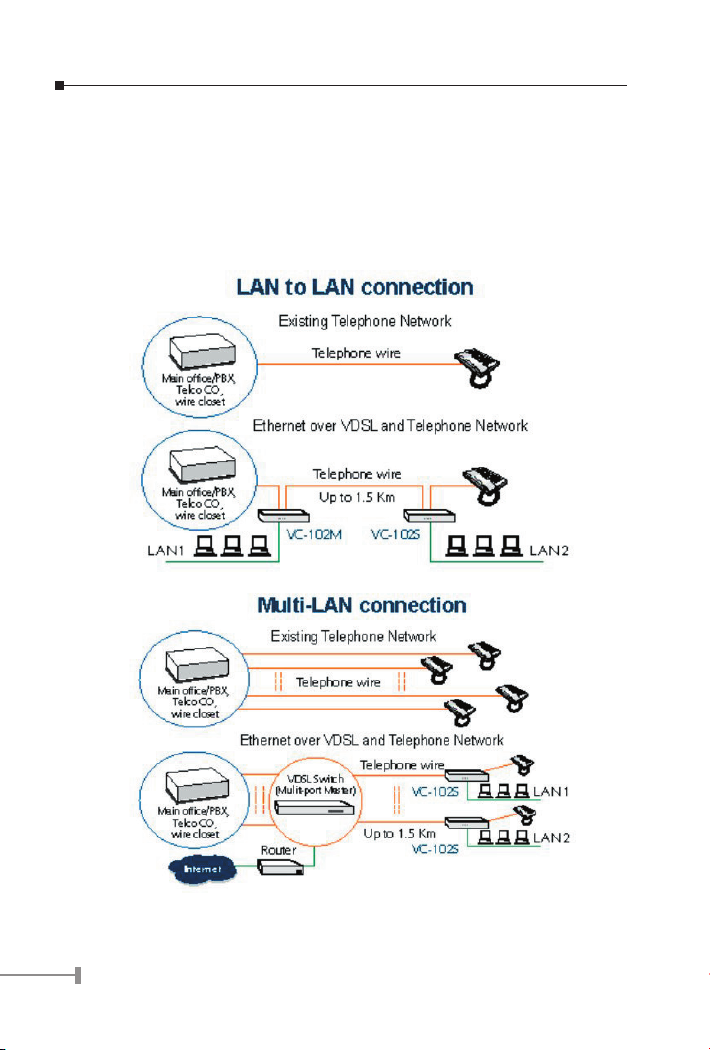
The two drawings listed below are typical application for the Ethernet over VDSL
converter.
2
Page 5

Note: Slave device must connect to Master device through the telephone
wire. Slave cannot connect to Slave and Master cannot connect to
Master. VC-102M works as Master device and VC-102S works as
Slave device.
1.3 Key Features
The converter provides the following key features:
• Cisco LRE switch / CPE compatible
• Complies with IEEE802.3, IEEE802.3u and IEEE802.3x standards
• 5 selectable transmission modes through DIP switch on VC-102M or manage-
ment interface of VC-1602
• QAM ( Quadrature Amplitude Modulation) line code
• Designed based on Frequency Division Duplex
• Half duplex Back pressure and IEEE802.3x Full Duplex Pause frame flow con-
trol
• Built-in POTS/ISDN splitter
• Two RJ-11 connectors for each VDSL port, one for VDSL connection and one for
POTS/ISDN connection
• Voice and data communication can be shared on the existing telephone wire
simultaneously
• Support up to 1536 bytes packet size, 802.1Q VLAN tag transparent
• Support extensive LED indicators for network diagnostics
3
Page 6
5
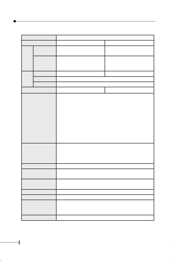
1.4 Specications
Product Ethernet over VDSL Converter
Model VC-102M VC-102S
10/100
Base-TX
Ports
VD S L(E a ch
with 2 RJ-11
connectors)
System PWR, STATUS PWR
LED
Ethernet 100, LNK/ACT, FDX/COL
VDSL LNK, ACT
DIP switch 5 positions DIP switch N/A
Mode/
Distance(Based on
AWG24 wires)
Cables
Splitter Built-in splitters for POTS/ISDN connection
System Memory
Dimensions
(WxDxH)
Mounting Type Desktop placement
Power Supply 12V/1A DC external power adapter
Operational Envi-
ronment
Certification FCC Class B, CE
1 RJ-45 1 RJ-45
1 (Master) 1 (Slave)
ANSI - 15/4Mbps asymmetrical rate up to 4100 feet
(1.25km)
ETSI - 11/4Mbps asymmetrical rate up to 4100 feet
(1.25km)
VE-5 - 5/5 Mbps symmetrical rate up to 5000 feet
(1.5km)
VE-10 - 11/11Mbps symmetrical rate up to 4100 feet
(1.25km)
VE-15 - 15/17Mbps asymmetrical rate up to 3500 feet
(1.05km)
10Base-T: 2-pair UTP Cat.3,4,5 up to 100m (328ft)
100Base-TX: 2-pair UTP Cat.5, up to 100m (328ft)
VDSL: twisted-pair telephone or ISDN wires (AWG24 or
better) up to 5000ft (1.5km)
8k bytes Ethernet transmit and 16k bytes Ethernet receive
buffers
117x93x25mm
Temperature: 0~50 degree C (operating), -20~70 degree
C (storage)
Humidity: 10~90%, non-condensing
4
Page 7

Standard Compli-
ance
IEEE 802.3 10Base-T
IEEE 802.3u 100Base-TX
IEEE802.3x Full Duplex PAUSE frame flow controlEthernet
over VDSL
5
Page 8

6
7
Page 9

Chapter 2
Hardware Description
This product series provide 2 RJ-11 ports for voice connection (like telephone or ISDN)
and for network line connection.
This product series also provide 1 RJ-45 ports for two different running speed –10Mbps,
100Mbps, in the same converter and automatically distinguish the speed of incoming
connection.
This section describes the hardware features of these Converters. For easier control
of the converter, familiarize yourself with its display indicators, and ports. Front panel
illustrations in this chapter display the unit LED indicators. Before connecting any network
device to the converter, read this chapter carefully.
2.1 Front Panel and Real Panel
The units’ front panel provides a simple interface monitoring the converter.
VC-102M Front Panell
VC-102S Front Panel
2.1.1 LED indicators
The rich diagnostic LEDs on the front panel can provide the operating status of individual
port and whole system.
STATUS LED (VC-102M only)
The LED blinks periodically to show the converter is working normally. If the LED stays
green/dark that means the system is fail, you need to contact your agent or try to reboot
the converter.
PWR LED
This indicator lights green when the converter is receiving power; otherwise, it is off.
7
Page 10

9
100 LED (Ethernet)
The RJ-45 port has a 100 LED. Steady green indicates that the port is operating at
100Mbps. If the LED is off, the link speed is 10Mbps.
LNK/ACT LED (Ethernet)
The RJ-45 port has a LNK/ACT LED. Steady green indicates that the port has good linkage
to its associated device. Flashing green indicates that the port is receiving or transmitting
data from/to its associated partner.
If the port is connected but the LNK/ACT LED is dark, check the following items:
1. The converter and the connected device’s power are on or not.
2. The port’s cable is firmly seated in its connectors in the switch and in the as-
sociated device.
3. The connecting cable is good and with correct type.
4. The connecting device, including any network adapter is functional.
FDX/COL LED (Ethernet)
A collision occurs when two stations within a collision domain attempt to transmit data at
the same time. Intermittent ashing amber of the collision LED is normal; the contending
adapters resolve each collision by means of a wait-then-retransmit algorithm. Frequency
of collisions is an indicator of heavy trafc on the network.
If the FDX/COL lights amber which means the port is under full-duplex operation or dark
for half-duplex mode.
LNK LED (VDSL)
If both ends of the VDSL devices are connected then the LED will blink for a while (in 10
seconds), this is the stage of speed auto-negotiation. After the negotiation process, the
LNK LED will stay green. If the LED blinks always, that means the link process is fail.
ACT LED (VDSL)
If there is any trafc transverses the port then the LED will light green. Otherwise, off
means no trafc on the network.
2.1.2 MODE DIP Switch (VC-102M only)
The converter provides 5 selective transmission modes that dened by predetermined
proles. By switching the transmission modes, you can obtain a best transmission mode
to suit with phone line quality or distance of connectivity. The following is the summary
table of transmission modes, bandwidth and distance extensibility tested for AWG 24
(0.5mm) twisted-pair without noise and cross talk.
Prole
Name
ANSI Public 15.17 4.27 4100 feet (1.25km)
ETSI Public 11.38 4.27 4100 feet (1.25km)
Prole
Type
Downstream
Rate (Mbps)
Upstream Rate
(Mbps)
Maximum Distance between
the Master and Slave device
8
Page 11

VE-5 Private 5.69 5.69 5000 feet (1.5km)
VE-10 Private 11.38 11.38 4100 feet (1.25km)
VE-15 Private 15.17 17.06 3500 feet (1.05km)
The following table lists the DIP switch settings for all 5 transmission mode. Please power
off the converter before making any transmission mode adjustment.
Transmission mode DIP switch
ANSI
ON
1 2 3 4
ETSI
ON
1 2 3 4
VE-5
ON
1 2 3 4
VE-10 (Default)
ON
1 2 3 4
VE-15
ON
1 2 3 4
2.2 The Rear Panel
The rear panel of the converter is shown below.
VC-102M and VC-102S require 12V DC power input. It will conform to the bundled AC
adapter. Should you have the problem to make the power connection, please contact your
local sales representative.
9
Page 12

11
Power Notice:
1.The device is a power-required device, it means, it will not work till it is
powered. If your networks should active all the time, please consider using
UPS (Uninterrupted Power Supply) for your device. It will prevent you from
network data loss or network downtime.
2.In some area, installing a surge suppression device may also help to protect
your converter from being damaged by unregulated surge or current to the
converter or the power adapter.
10
Page 13

Chapter 3
Installing and Using VDSL Converter
3.1 Install the Ethernet Over VDSL Converter
The Converter does not require any software conguration. Users can immediately use
any feature of this product simply by attached the cables and plug power on. There is
some key limitation on the Ethernet over VDSL converter. Please check the following
items:
• The device is used for point-to-point connection only (master device to slave
device) and allows data and voice work on the same telephone or ISDN lines.
• Two RJ-11 connectors for VDSL port. One for voice device connection (like
telephone) and the other one for network link connection.
• Depending on the quality of telephone line, the maximum distance of one VDSL
segment is 1.5km (5000ft) with AWG 24 telephone wires. The distance will
change by the quality of telephone wires.
3.1.1 LAN to LAN connection
Two sets of the converters could be used to link two local Area networks that are located
in different areas. Through the normal telephone line, it could setup an up to 15/17Mbps
asymmetric backbone, but one converter must be Master (VC-102M) and the other one
is Slave (VC-102S).
NOTE: VC-102M can be connected PLANET’s previous slave model, VC-101S.
The speed is also adjusted by the DIP-switch of VC-102M. VC-102S
can also be connected to previous master, VC-101M. The speed
depends on the firmware loaded on VC-101M. Please check the VC101M’s user’s manual for detail.
3.1.2 Connect to Multi-Port Master
In order, to built up a local Internet in apartment, hotel, campus and hospitality
environment.
The Multi-port Master (for example, VC-1602, VC-412 or Cisco LRE switch) need to be
placed In the wiring center (MDF room) and connect to the telephone line system, on the
other hand, need to install a Slave (VC-102S) converter on the individual client side and
connect to the Multi-port Master through the telephone lines.
When deciding where to put the converter then you must ensure:
n It is accessible and cables can be connected easily. Cabling is away from
sources of electrical noise such as radios, transmitters and power lines and
fluorescent lighting fixtures.
n Water or moisture can not enter the unit
11
Page 14

13
n Air flow around the unit and through the vents in the side of the case is not
restricted (company recommend that you provide a minimum of 25mm inch
clearance)
To prolong the operational life of your units:
n Do not place objects on top of any unit or stack
n Do not obstruct any vents at the sides of the case
3.2 Connecting VC-102M/S
3.2.1 Connecting Standalone PC
Refer to the following procedures to setup the VC-102M/S to a standalone PC.
1. Power on the VC-102M/S by connecting its power source.
2. Power LED will illuminate.
3. Connect VDSL line from another VDSL device to VDSL port of the VC-102M/S.
4. LNK LED will illuminate.
5. Connect telephone to the POTS port.
6. Connect Ethernet port to PC Network Interface Card (NIC) via regular Cat. 5
cable.
3.2.2 Connecting Multiple PCs to an Ethernet LAN
Refer to the following procedures to setup the VC-102M/S to an Ethernet LAN.
1. Power on the VC-102M/S by connecting its power source.
2. Power LED will illuminate.
3. Connect VDSL line from another VDSL device to VDSL port of the VC-102M/S.
4. LNK LED will illuminate.
12
Page 15

5. Connect telephone to the POTS port.
6. Connect Ethernet port to Ethernet device via regular Cat. 5 cable.
NOTE: Please refer to your Ethernet device User’s Manual for the device’s set
up information.
13
Page 16

15
Chapter 4
Troubleshooting
SYMPTOM: VDSL LNK LED does not lit after wire is connected to the VDSL port.
CHECKPOINT:
1: Verify the length of the wire connected between VC-102M and VC-102S is not
more than 1.5km. Please also try to adjust the DIP switch or VC-102M to other
speed mode.
2: Please note you must use 1 VC-102M and 1 VC-102S connect to each other to
make it work.
SYMPTOM: Switch LNK/ACT LED does not lit after cable is connected to the port.
CHECKPOINT:
1: Verify you are using the Cat.5 or better cable with RJ-45 connector to connect
to the port.
2: If your device (like LAN card) supports to Auto-Negotiation, please try to
manual set at a fixed speed of your device to solve this problem.
14
Page 17

15
Page 18

Part No.:EM-VC102
 Loading...