

Page 1
Page 2

Trademarks
Copyright PLANET Technology Corp. 2002.
Contents subject to revise without prior notice.
PLANET is a registered trademark of PLANET
Technology Corp. All other trademarks belong to their
respective owners.
FCC Warning
This equipment has been tested and found to comply
with the limits for a Class B digital device, pursuant to
Part 15 of the FCC Rules. These limits are designed to
provide reasonable protection against harmful
interference in a residential installation, This
equipment generates, uses, and can radiate radio
frequency energy and, if not installed and used in
accordance with the Instruction manual, may cause
harmful interference to radio communications,
however, there is no guarantee that interface will not
occur in a particular installation. If this equipment does
cause harmful interference to radio or television
reception, which can be determined by turning the
equipment off and on.
CE Mark Warning
This is a Class B product. In a domestic environment,
this product may cause radio interference, in which
case the user may be required to take adequate
measures.
Revision
Ethernet Over VDSL Converter User's Manual
FOR MODELS: VC-101M / VC-101S
Part No.: EM-VC101V2
2
Page 3

TABLE OF CONTENTS
1. INTRODUCTION.........................................................5
1.1 Checklist..................................................................... 5
1.2 Introduction to Ethernet over VDSL Converter ...... 5
1.3 Key Features.............................................................. 8
1.4 Specifications ............................................................ 9
2. HARDWARE DESCRIPTION....................................11
2.1 Front Panel and Real Panel .................................... 12
2.1.1 LED indicators..................................................... 13
2.1.2 Power Source...................................................... 14
2.2 Bottom Panel............................................................ 14
3. INSTALLING AND USING VDSL CONVERTER....16
3.1 Install the Ethernet Over VDSL Converter ............ 16
3.2 LAN to LAN connection .......................................... 16
3.3 Connect to Multi-Port Master ................................. 17
3.4 Connecting VC-101M/S ........................................... 18
3.4.1 Connecting Standalone PC................................. 18
3.4.2 Connecting Multiple PCs to an Ethernet LAN..... 18
4. UPDATE FIRMWARE...............................................20
4.1 Firmware version..................................................... 20
4.2 Update Procedure.................................................... 21
5. TROUBLESHOOTING..............................................25
3
Page 4

This page intentionally left blank!
4
Page 5

1. Introduction
1.1 Checklist
Check the contents of your package for following parts:
Ethernet over VDSL Converter
Power Adapter
Telephone line
Cat.5 Ethernet Cable
Quick Installation Guide
User’s manual and utility CD
RS-232 Console cable(VC-101M only)
If any of these pieces are missing or damaged, please
contact your dealer immediately, if possible, retain the carton
including the original packing material, and use them against
to repack the product in case there is a need to return it to us
for repair.
1.2 Introduction to Ethernet over VDSL Converter
The converter is a switching architecture with one RJ45
10/100Mbps Fast Ethernet ports and one RJ11 symmetric
Ethernet over VDSL port (symmetry means upstream and
downstream rate are the same or similar). It is ideal for signal
conversion by transmitting the Ethernet data from the
standard twisted pair cable to the telephone cable and
extending the distance.
The Ethernet over VDSL combines the well proven Ethernet
and VDSL technology to transmit the Ethernet format data by
using VDSL signaling over the most widespread telephone
wires and has no impact to current voice service. Therefore,
it is very good for Internet building phone line network
because every room or house could use the existing phone
line to transmit data to the Internet and the whole building
5
Page 6

could share the Internet line to the wide area network with
minimum cost.
With much enough bandwidth, the 5/10/15 Mbps symmetric
capability enables many multi-media services on local
Internet come true, like VOD (Video on Demand), Internet
caching server, distance education, and so on.
In one community or hotel, we just need to install one local
server then the multi-media services will be localized that is
people do not need to access the services through Internet
but using local area network with better bandwidth and
efficiency. Meanwhile, this kind of infrastructure will minimize
the burden on the Internet.
The converter is plug-n-play without any software to
configure and also fully compliant with all kinds of network
protocols. Moreover, the rich diagnostic LEDs on the
front-panel provide the operating status of individual port and
the whole system. There are two models of the converters,
one is used for client side and the other is central side. If you
want to setup one pair of converters for point-to-point
connection then one set must be slave (client) mode and the
other one is master mode.
The cable specifications of the connection are listed as
following:
10BASE-T, Category 3, 4 or 5 UTP
100BASE-TX, Category 5 UTP
Ethernet over VDSL, Twisted-pair telephone wires
The two drawings listed below are typical application for the
Ethernet over VDSL converter.
6
Page 7
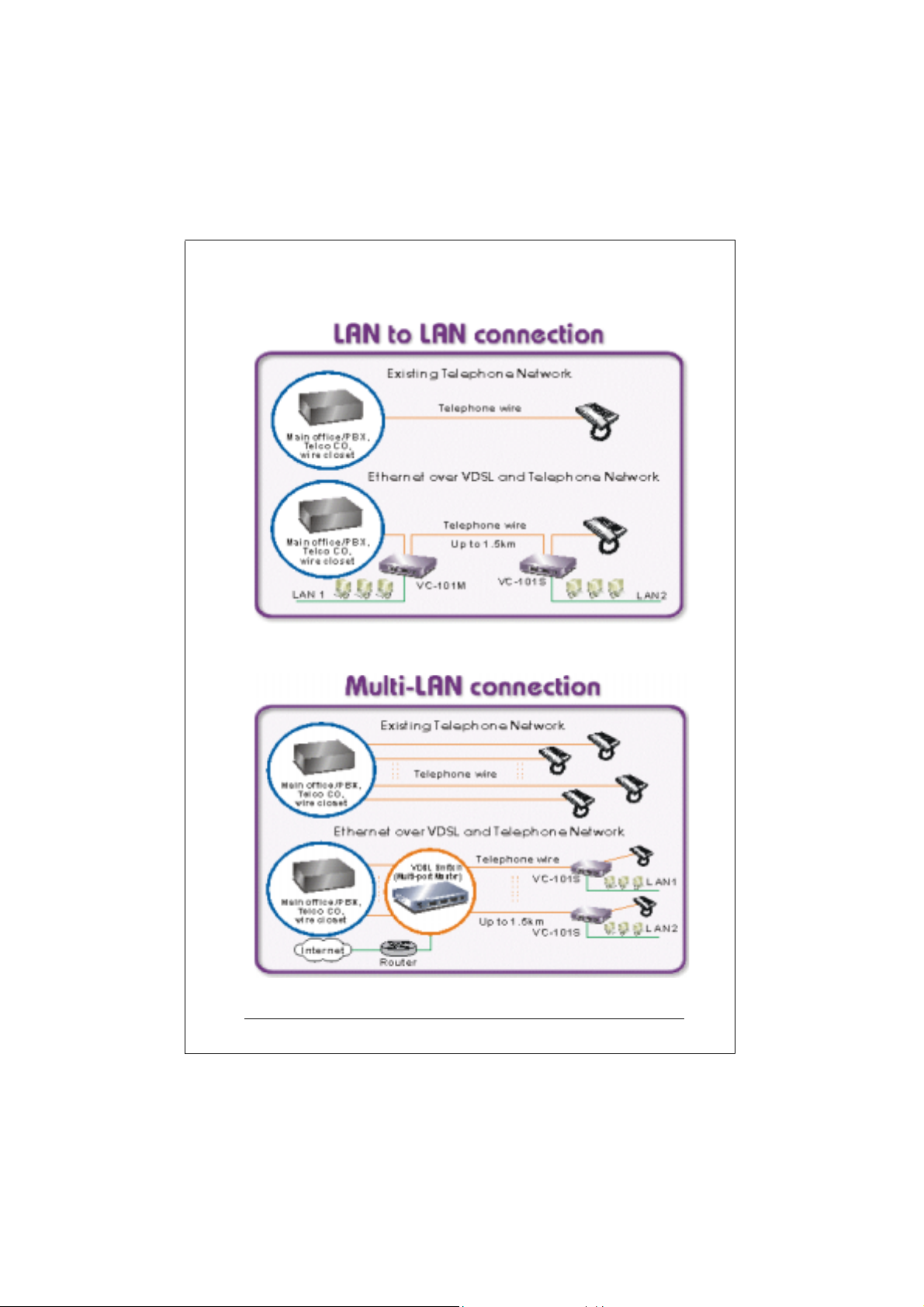
Drawing 1: LAN to LAN connection
Drawing 2: Multi-port Master Connection
7
Page 8

Note: Slave device must connect to Master device
through the telephone wire. Slave cannot
connect to Slave and Master cannot connect to
Master. VC-101M works as Master device and
VC-101S works as Slave device.
1.3 Key Features
The converter provides the following key features:
Firmware upgradeable through console interface
11Mbps symmetric data rate in maximum 1.2km with
R2 firmware
17Mbps upstream and 15Mbps downstream data
rate in maximum 1.05 km with R4 firmware
1/4, 5/5, 11/11 and 17/15 Mbps adjustable data rate
with R4.5 firmware (when VC-101S works with
VC-412 only)
Cisco LRE switch / CPE compatible with R4.5
firmware
Complies with IEEE802.3, IEEE802.3u and
IEEE802.3x standards
Designed based on QAM modulation
Designed based on FDD duplexing (Frequency
Division Duplexing)
Supports Store-and-forward mechanism
Back pressure and IEEE802.3x compliant flow
control
Built-in POTS/ISDN splitter
Two RJ-11 connectors for each VDSL port, one for
VDSL connection and one for POTS/ISDN
connection
Voice and data communication can be shared on the
existing telephone wire simultaneously
Support extensive LED indicators for network
diagnostics
8
Page 9

1.4 Specifications
Model VC-101M VC-101S
10/100Base-TX 1 RJ-45 1 RJ-45 Ports
VDSL
(Each with 2
RJ-11
connectors)
Console 1 x RS-232 DB-9
Mode/Distance
(based on AWG24
wires)
Cables 10Base-T: 2-pair UTP Cat. 3,4,5
Protocols and
Standards
Splitter Built-in splitters for POTS/ISDN
Mounting Type Desktop placement
Dimensions (WxDxH) 140 x 91.6 x 30 mm
Power Supply 5V/2A DC external power adapter
Operational
Environment
Certification FCC, CE
1 (Master) 1 (Slave)
R2 firmware: 11Mbps upstream and
downstream
R4 firmware: 17Mbps upstream and
15Mbps downstream
R4.5 firmware: 5/10/15 adjustable
between VC-101S and VC-412
up to 100m (328ft)
100Base-TX: 2-pair UTP Cat.5, up to
100m (328ft)
VDSL: twisted-pair telephone or
ISDN wires (AWG26 or better) up to
5000ft (1.5km)
IEEE 802.3 (Ethernet)
IEEE 802.3u (Fast Ethernet)
IEEE 802.3x (flow control)
Ethernet over VDSL
connection
Temperature: 0~50 degree C
(operating), -20~70 degree C
(storage)
Humidity: 0~90%, non-condensing
9
Page 10

10
Page 11

This page intentionally left blank!
11
Page 12

2. Hardware Description
This product series provide 2 RJ-11 ports for voice
connection (like telephone or ISDN) and for network line
connection.
This product series also provide 1 RJ-45 ports for two
different running speed –10Mbps, 100Mbps, in the same
converter and automatically distinguish the speed of
incoming connection.
This section describes the hardware features of these
Converters. For easier control of the converter, familiarize
yourself with its display indicators, and ports. Front panel
illustrations in this chapter display the unit LED indicators.
Before connecting any network device to the converter, read
this chapter carefully.
2.1 Front Panel and Real Panel
The units’ front and real panel provides a simple interface
monitoring the converter .
12
VC-101M and VC-101S front panel
VC-101M and VC-101S rear panel
Page 13

2.1.1 LED indicators
LED Function Color Status Description
Power Power indication Green
On Power on
Off Power off
VDSL Ports
Sync VDSL link Green
On
Off No VDSL link
On
Err Errors on line Yellow
Off No error
VDSL link is
established
Errors has
occurred on the
line
Ethernet Ports
On
LNK Ethernet link Green
Off
On Full Duplex*1
FDX/
COL
10/100 Speed Green
ACT Data Flow Green
NOTE: The current firmware have not supported Full Duplex.
Ethernet port Full
duplex
Yellow
Blinking
Off
On
Off
On
Off Not active
Ethernet link is
established
No Ethernet link
is established
Half duplex and
Transmission
collisions have
occurred
Half duplex no
collision
Speed is at 100
Mbps
Speed is at 10
Mbps
Sending and
delivering data
13
Page 14

2.1.2 Power Source
VC-101M and VC-101S require +5VDC power input. It will
conform to the bundled AC adapter. Should you have the
problem to make the power connection, please contact your
local sales representative.
Power Notice:
1. The device is a power-required device, it means, it will not
work till it is powered. If your networks should active all the
time, please consider using UPS (Uninterrupted Power
Supply) for your device. It will prevent you from network
data loss or network downtime.
2. In some area, installing a surge suppression device may
also help to protect your converter from being damaged by
unregulated surge or current to the converter or the power
adapter.
2.2 Bottom Panel
The VC-101M/S can be installed on a desk or mounted on a
wall. To mount the VC-101M/S on the wall simply hook holes
on the bottom of the VC-101M/S to stable anchors on the wall.
14
Wall mounting holes
Page 15

This page intentionally left blank!
15
Page 16

3. Installing and Using VDSL Converter
3.1 Install the Ethernet Over VDSL Converter
The Converter does not require any software configuration.
Users can immediately use any feature of this product simply
by attached the cables and plug power on. There is some
key limitation on the Ethernet over VDSL converter. Please
check the following items:
The device is used for point-to-point connection only
and allows data and voice work on the same telephone
or ISDN lines.
Two RJ-11 connectors for VDSL port. One for voice
device connection (like telephone) and the other one for
network link connection.
Depending on the quality of telephone line, the
maximum distance of one VDSL segment is 1.2km
(4000ft) with AWG 24 telephone wires. The distance
will change by the quality of telephone wires.
3.2 LAN to LAN connection
Two sets of the converters could be used to link two local
Area networks that are located in different areas. Through
the normal telephone line, it could setup a 1 1Mbps symmetric
backbone, but one converter must be Master(VC-101M) and
the other one is Slave(VC-101S).
16
Page 17

3.3 Connect to Multi-Port Master
In order, to built up a local Internet in apartment, hotel,
campus and hospitality environment.
The Multi-port Master (for example, VC-412 or Cisco LRE
switch) need to be placed In the wiring center (MDF room)
and connect to the telephone line system, on the other hand,
need to install a Slave(VC-101S) converter on the individual
client side and connect to the Multi Port Master through the
telephone lines.
Multi-Port Master (VC-412)
When deciding where to put the converter then you must
ensure:
It is accessible and cables can be connected easily.
Cabling is away from sources of electrical noise such
as radios, transmitters and power lines and
fluorescent lighting fixtures.
Water or moisture can not enter the unit
Air flow around the unit and through the vents in the
side of the case is not restricted (company
recommend that you provide a minimum of 25mm
inch clearance)
To prolong the operational life of your units:
Do not place objects on top of any unit or stack
Do not obstruct any vents at the sides of the case
17
Page 18

3.4 Connecting VC-101M/S
3.4.1 Connecting Standalone PC
Refer to the following procedures to setup the VC-101M/S to
a standalone PC.
1. Power on the VC-101M/S by connecting its power
source.
2. Power LED will illuminate.
3. Connect VDSL line from another VDSL device to VDSL
port of the VC-101M/S.
4. SYNC LED will illuminate.
5. Connect telephone to the POTS port.
6. Connect Ethernet port to PC Network Interface Card
RJ-11
Phone
Jack
RJ-11 Line Cord
(NIC) via regular Cat. 5 cable.
VDSL POTS
POWER
SYNC
ERR
FDX/COL ACT
CN-501
5V@2A
CN-501 RT
VC-101M/S
VDSL Modem
Cat. 5 Ethernet Cable
(Straight-through)
10/100 Base-Tx
LNK
10/100
RESET
=X
RJ-11 Line Cord
123
456
789
8#
*
NIC Cable Connection
3.4.2 Connecting Multiple PCs to an Ethernet LAN
Refer to the following procedures to setup the VC-101M/S to
an Ethernet LAN.
1. Power on the VC-101M/S by connecting its power
source.
2. Power LED will illuminate.
3. Connect VDSL line from another VDSL device to VDSL
port of the VC-101M/S.
4. SYNC LED will illuminate.
18
Page 19

5. Connect telephone to the POTS port.
6. Connect Ethernet port to Ethernet device via regular
Cat. 5 cable.
Note: Please refer to your Ethernet device User’s Manual for
the device’s set up information.
VC-101M/S
CN-501 VDSL Modem
VDSL POTS
10/100 Base-Tx
LNK
10/100
Regular Phone Cord
RJ-11
Wallplate
Regular Phone Cord
POWER
SYNC
ERR
CN-501
RESET
FDX/COLACT
=X
5V@2A
Cat. 5 Ethernet Cable (Straight)
Hub
12x6x8x2x9x3x10x4x11x5x7x
C
Ethernet
A
12x6x8x2x9x3x10x4x11x5x7x
789101112
123456
1x
1x
B
A
123
456
789
8#
*
Cat. 5 Ethernet Cable
(Straight)
Cat. 5 Ethernet Cable
(Straight)
Telephone
NIC Cable Co n nection
19
Page 20

4. Update Firmware
4.1 Firmware version
In order for VDSL local and remote converters to
communicate, both remote and local ends must set to the
same communication speed. If speeds are different then
remote and local modems will not link. The factory default
firmware (R2) of VC-101M/S supports symmetric 11Mbps
data rate. The data rate can be increase to 15Mbps
downstream and 17Mbps upstream in trade off shorter
distance by update the firmware to R4 version. PLANET also
provides a R4.5 firmware for VC-101S to work with VC-412
and Cisco’s LRE switch. The following table lists the
feature of R2, R4 and R4.5 firmware.
Upstream (Mbps) Downstream(Mbps) Firmware
version
R2
(default)
R4 18.75 17.06 16.67 15.17 1.05km
R4.5 1.56
Line speed Data rate Line speed Data rate
12.5 11.38 12.5 11.38 1.2km
6.25
12.5
18.75
1.43
5.69
11.38
17.06
4.17
6.25
12.5
16.67
3.77
5.69
11.38
15.17
Note: The distance is based on good cable quality and
connection status. The actual distance can be reduced by
the following factors:
1. The age and type of the wiring.
2. The quality of the cable.
3. Each terminated bridge tap may reduce the distances by
300 feet.
4. If it run over bundled telco cabling, the maximum distance
supported can be approximately 30 percent lower due to
cross talk and interference.
5. The 5/10/15 data rate for R4.5 is only applicable betwee n
VC-101S and VC-412. If connect VC-101M and VC-101S
with R4.5 firmware, the speed is only 4/1 Mbps.
Maximum
Distance
1.5km
1.5km
1.2km
1.05km
20
Page 21

4.2 Update Procedure
Users can adjust transmission speeds manually through an
application called the “E2PROM Programmer” created by
Infineon. This program can be found on “Utility” directory of
bundled CD. Before running this program, please note that
it is only for the following operation systems:
1. Windows 95, 98, NT, Me English version.
2. Windows 2000 and XP
However, Windows 2000 and XP should be configured to
use English as default language settings for the system. To
configure this,
Windows 2000: Click “Start” -> “Settings” -> “Control Panel”
-> “Regional Options” -> “General” tab. Click “Set default”
button and select “English [United States] as default
language settings.
Windows XP: Click “Start” -> “Settings” -> “Control Panel” ->
“Regional and Language Options” -> “Advanced” tab. On
the ”Language for Non-Unicode programs” list, select
“English [United States]”.
Below are the procedures to change its speed through
“E2PROM Programmer”.
1. Connect VC-101 console port to a PC COM port. (DB9
to DB9 Cable)
2. Launch the “E2Prom Programmer” application.
3. Select “PEF22822 V2.2” option from the drop-down
menu.
4. Press the “Continue” button.
21
Page 22

5. Press “Open File” button to open the firmware file to be
upload to the VC-101.
Note: The firmware file should be placed on directory
with only English character .
6. Locate and open the corresponding version of firmware
file to be uploaded.
7. Press “Program” button to upload the file.
22
Page 23

8. Select the COM port which the VC-101 is connected to.
9. Press “OK” button.
10. Repeat steps 1 to 9 for another VC-101.
11. Disconnect the console cable from VC-101 and PC
COM port when finished.
To verify the new setting:
I. Connect the VC-101M and VC-101S and make sure they
are linked. (If connection does not establish might due to
distance restriction or environment factors)
II. Connect the VC-101M and a PC through console port via
console cable. (DB-9 to DB-9 cable)
III. Launch terminal application and set its settings to:
Baud Rate: 9600
Data Bits: 8
Parity: None
Stop Bits: 1
Flow Control: None
IV. Once connect you will be able to see the command
prompt L>
Observe: “L>” represents the command prompt at
VC-101M(local modem, the console cable connected unit is
consider the local one), to toggle to the VC-101S(remote
modem), press [CTRL+E] on the keyboard, you should see
23
Page 24

the command prompt change to “R>".
V. Toggle to the VC-101S by holding and releasing
[CTRL+E].
VI. Issue the command RD C020,4 at the command prompt
to read the speed of the VC-101M/S.
VII. Compare the displayed variables with the variable in the
table below to determine your VC-101M/S’s speed.
Variables for 11 Mbps upstream/11 Mbps downstream (R2)
32 24 4F 00
Variables for 17 Mbps upstream/15 Mbps downstream (R4)
31 22 4F 00
VIII. Toggle back to the VC-101M by pressing and releasing
[CTRL+E].
IX. Issue the same commands that issued in VC-101S.
24
Page 25

5. Troubleshooting
SYMPTOM: VDSL link LED not lit after wire is connected
to the VDSL port.
CHECKPOINT:
1: Verify the length of the wire con nected between
VC-101M and VC-101S is not more than 1.5km.
2: Please note you must use 1 VC-101M and 1 VC-101S
connect to each other to make it work.
SYMPTOM: Switch Link/Act LED not lit after cable is
connected to the port.
CHECKPOINT:
1: Verify use the RJ-45 cable connected to the port.
2: If your device (like LAN card) support to
Auto-Negotiation, please try to manual set at a fixed
speed of your device to solve this problem.
25
Page 26

EM-VC101V1
 Loading...