

Page 1

User’s Manual of UPOE-800G/UPOE-1600G/UPOE-2400G
1
Page 2

User’s Manual of UPOE-800G/UPOE-1600G/UPOE-2400G
Trademarks
Copyright © PLANET Technology Corp. 2017.
Contents are subject to revision without prior notice.
PLANET is a registered trademark of PLANET Technology Corp. All other trademarks belong to their respective owners.
Disclaimer
PLANET Technology does not warrant that the hardware will work properly in all environments and applications, and
makes no warranty and representation, either implied or expressed, with respect to the quality, performance,
merchantability, or fitness for a particular purpose. PLANET has made every effort to ensure that this User's Manual is
accurate; PLANET disclaims liability for any inaccuracies or omissions that may have occurred.
Information in this User's Manual is subject to change without notice and does not represent a commitment on the part of
PLANET. PLANET assumes no responsibility for any inaccuracies that may be contained in this User's Manual. PLANET
makes no commitment to update or keep current the information in this User's Manual, and reserves the right to make
improvements to this User's Manual and/or to the products described in this User's Manual, at any time without notice.
If you find information in this m anual t hat i s in corr e ct, m isl ead ing, or incomplete, we would appr ec iate y our com men ts a n d
suggestions.
FCC Warning
This equipment has been tested and found to comply with the limits for a Class A digital device, pursuant to Part 15 of the
FCC Rules. These limits are designed to prov ide reasonable p rotection agai nst harmful inter ference w hen the equipment is
operated in a commercial environment. T his equipment g enerates, uses, a nd can radiate r adio frequency energy and, if no t
installed and used in accordance with the Instruction manual, may cause harmful interference to radio communications.
Operation of this equipment in a residential area is likely to cause harmful interference in which case the user will be
required to correct the interference at his own expense.
CE Mark Warning
This is a Class A product. In a domestic environment, this product may cause radio interference, in which case the user
may be required to take adequate measures.
Energy Saving Note of the Device
This power required device d oes not support S tandby mode operat ion. F or ener gy saving, plea se remov e the pow er cabl e
to disconnect the device from the power circuit. In view of saving the energy and reducing the unnecessary power
consumption, it is strongly suggested to remove the power connection for the device if this device is not intended to be
active.
WEEE Warning
To avoid the potential effects on the environment and human health as a result of the presence of
hazardous substances in electrical and electronic equipment, end users of electrical and electronic
equipment should understand the meaning of the crossed-out wheeled bin symbol. Do not dispose of
WEEE as unsorted municipal waste and have to collect such WEEE separately .
Revision
PLANET 8-/16-/24-Port Gigabit 60 W Ultra PoE Managed Injector Hub User's Manual
FOR MODELS:
REVISION: 1.0 (JANUARY, 2017)
Part No.: EM-UPOE-800G_1600G_2400G_v1.
UPOE-800G, UPOE-1600G, UPOE-2400G
2
Page 3

User’s Manual of UPOE-800G/UPOE-1600G/UPOE-2400G
TABLE OF CONTENTS
1. INTRODUCTION ....................................................................................... 5
1.1 PACKAGE CONTENTS ..................................................................................................... 5
1.2 PRODUCT DESCRIPTION ................................................................................................. 6
1.3 HOW TO USE THIS MANUAL .......................................................................................... 12
1.4 PRODUCT FEATURES ................................................................................................... 13
1.5 PRODUCT SPECIFICATIONS ........................................................................................... 15
2. INSTALLATION ...................................................................................... 17
2.1 HARDWARE DESCRIPTION ............................................................................................ 17
2.1.1 Injector Front Panel .......................................................................................... 17
2.1.2 LED Indicators .................................................................................................. 18
2.1.3 Injector Rear Panel ........................................................................................... 20
2.2 INSTALLING THE ULTRA POE MANAGED INJECTOR HUB ................................................. 20
2.2.1 Desktop Installation .......................................................................................... 20
2.2.2 Rack Mounting ................................................................................................. 21
2.2.3 Network Application Installation ........................................................................ 23
2.2.4 Power over Ethernet Powered Device .............................................................. 24
3 Management ............................................................................................ 25
3.1 OVERVIEW .................................................................................................................. 25
3.2 REQUIREMENTS ........................................................................................................... 25
3.3 MANAGEMENT METHOD ............................................................................................... 26
3.3.1 Web Management ............................................................................................ 26
3.3.2 PLANET Smart Discovery Utility ...................................................................... 27
4 WEB CONFIGURATION .......................................................................... 29
4.1 MAIN MENU ................................................................................................................. 29
4.2 WEB PANEL ................................................................................................................ 30
4.3 SYSTEM ...................................................................................................................... 30
4.3.1 System Information ........................................................................................... 31
4.3.2 IP Configuration ................................................................................................ 32
4.3.3 NTP Configuration ............................................................................................ 33
4.3.4 Password Setting ............................................................................................. 34
4.3.5 Firmware Upgrade ............................................................................................ 35
3
Page 4

User’s Manual of UPOE-800G/UPOE-1600G/UPOE-2400G
4.3.6 Configuration Setting ........................................................................................ 36
4.3.7 Factory Default ................................................................................................. 38
4.3.8 System Log ...................................................................................................... 40
4.3.9 System Reboot ................................................................................................. 41
4.3.10 Logout ............................................................................................................ 42
4.4 SNMP ........................................................................................................................ 44
4.4.1 SNMP Management ......................................................................................... 44
4.5 POWER OVER ETHERNET .............................................................................................. 46
4.5.1 PoE Configuration ............................................................................................ 47
4.5.2 PoE Schedule Profile ........................................................................................ 49
4.5.3 PoE Alive Check Configuration ........................................................................ 53
4.5.4 PoE Status ....................................................................................................... 54
5. Power OVER Ethernet Overview ........................................................... 55
6. The PoE Provision Process .................................................................. 57
6.1 LINE DETECTION .......................................................................................................... 57
6.2 CLASSIFICATION .......................................................................................................... 57
6.3 START-UP ................................................................................................................... 58
6.4 OPERATION ................................................................................................................. 58
6.5 POWER DISCONNECTION SCENARIOS ............................................................................ 58
APPENDIX A ............................................................................................... 59
A.1 MDI SETTINGS ............................................................................................................ 59
A.2 POWER DEVICE CLASSIFICATION VALUES ..................................................................... 59
A.3 DATA OUT POE INJECTOR RJ45 PORT PIN ASSIGNMENTS .......................................... 60
4
Page 5

8-Port Gigabit 60W Ultra PoE Managed Injector Hub (400 watts)
User’s Manual of UPOE-800G/UPOE-1600G/UPOE-2400G
1. INTRODUCTION
Thank you for purchasing PLANET 8-/16-/24-Port Gigabit 60W Ultra PoE Managed Injector Hub,
UPOE-800G/UPOE-1600G/UPOE-2400G.
The description of this series is shown below:
UPOE-800G
UPOE-1600G
UPOE-2400G
16-Port Gigabit 60W Ultra PoE Managed Injector Hub (600 watts)
24-Port Gigabit 60W Ultra PoE Managed Injector Hub (800 watts)
1.1 Package Contents
Open the box of the Ultr a PoE M anaged Injector Hub and carefully unpack it. The box s hould contain the following items:
The UPOE-800G,UPOE-1600G or UPOE-2400G x 1
Quick Installation Guide x 1
Power Cord x 1
Rubber Feet x 4
19” Rack-mounting Brackets x 2
If any of these are m is sin g or damaged, please c ont a ct y o ur d ealer immediately; if possible, retain the carton including the
original packing material, and use them again to repack the product in case there is a need to return it to us for repair.
In the following section, the term “Ultra PoE Managed Injector Hub” mentioned in this user’s manual refers to the
UPOE-800G/UPOE-1600G/UPOE-2400G.
5
Page 6
User’s Manual of UPOE-800G/UPOE-1600G/UPOE-2400G
1.2 Product Description
PLANET Ultra PoE Managed Injector Hub series, a cost -effective and quick Ultra PoE solution, is designed to perfectly
upgrade an existing network infrastructure to Ultra Power over Ethernet network system without replacing the existing
Ethernet Switch.
Ready to Deploy Next Generation Power over Ethernet
The Ultra PoE Managed Injector Hub is a high-density, rack-mountable managed Ultra PoE Managed Injector Hub
featuring PLANET intelligent PoE functions through web user interface for remote mana g emen t. It provide s 8/16/24
10/100/1000BASE-T Ethernet por ts feat uring Ultra PoE injector with a total PoE budget of 400/600/800 watts. Each PoE
port can deliver up to 60-watt power over Cat.5/5e/6 Ethernet UTP cables which allow data and power to transmit
simultaneously to a remote 60W and 802.3at/af powered device (PD).
The Ultra PoE Managed Injector Hub enables centralization of the power supply and optimizes the installation and power
management of remote network devices, and provides a quick, safe and cost-effective Power over Ethernet network
solution for small businesses and enterpri se s.
Quick and Easy PoE Network Deployment
The Ultra PoE Managed Injector Hub is installed between a regular Ethernet Switch and the PDs. There are totally
16/32/48 RJ45 STP ports on the front panel of the Ultra PoE Managed Injector Hub, of which the 8/16/24 ports are on the
lower stack funct ion ed as "Data input" while the other 8/16/24 ports are on the upper stack functioned as "PoE (Data and
Power) output". Both power and data are transferred simultaneously over the UTP cables to PDs without affecting the
existing network performance and functions. With data and Power over Ethernet from one unit, the Ultra PoE Managed
Injector Hub can reduce power cable dep loyme nt and elimin ate the n eed for ded icated electr ical ou tlet s on t he wall, c eilin g
or any unreachable place.
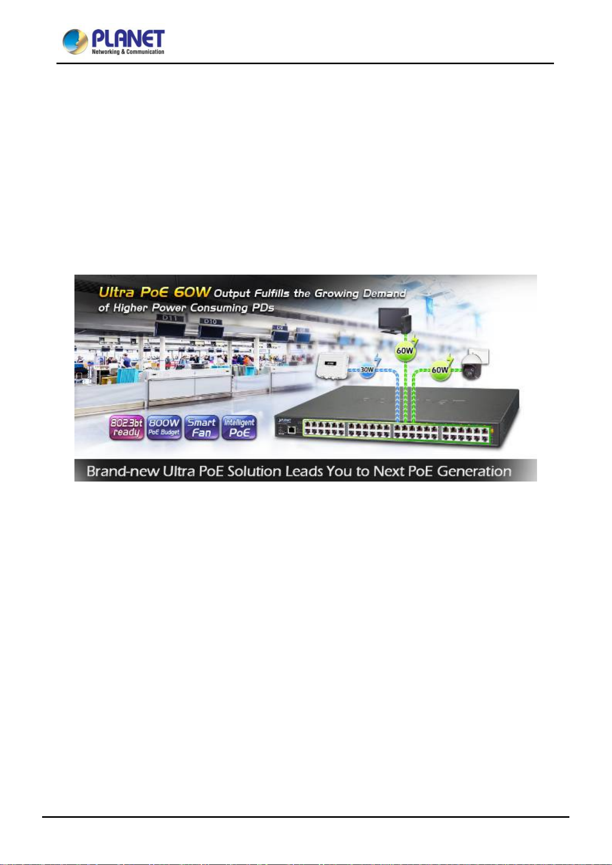
802.3bt Ready -- 60 Watts of Power over 4-pair UTP System
The Ultra PoE Managed Injector Hub solution adopts the IEEE 802.3at/af PoE standard. Instead of delivering power over
2-pair twisted UTP – be it end-span (Pins 1, 2, 3 and 6) or mid-span (Pins 4, 5, 7 and 8), it provides the capab ility t o sour ce
up to 60 watts of power by usin g all the four pair s of standar d Cat.5e/6 Ether net cabli ng. In the new 4-pair sy stem, the Ultra
PoE Managed Injector Hub is able to deliver per port up to 60 watts of power to each remote PoE compliant powered
6
Page 7
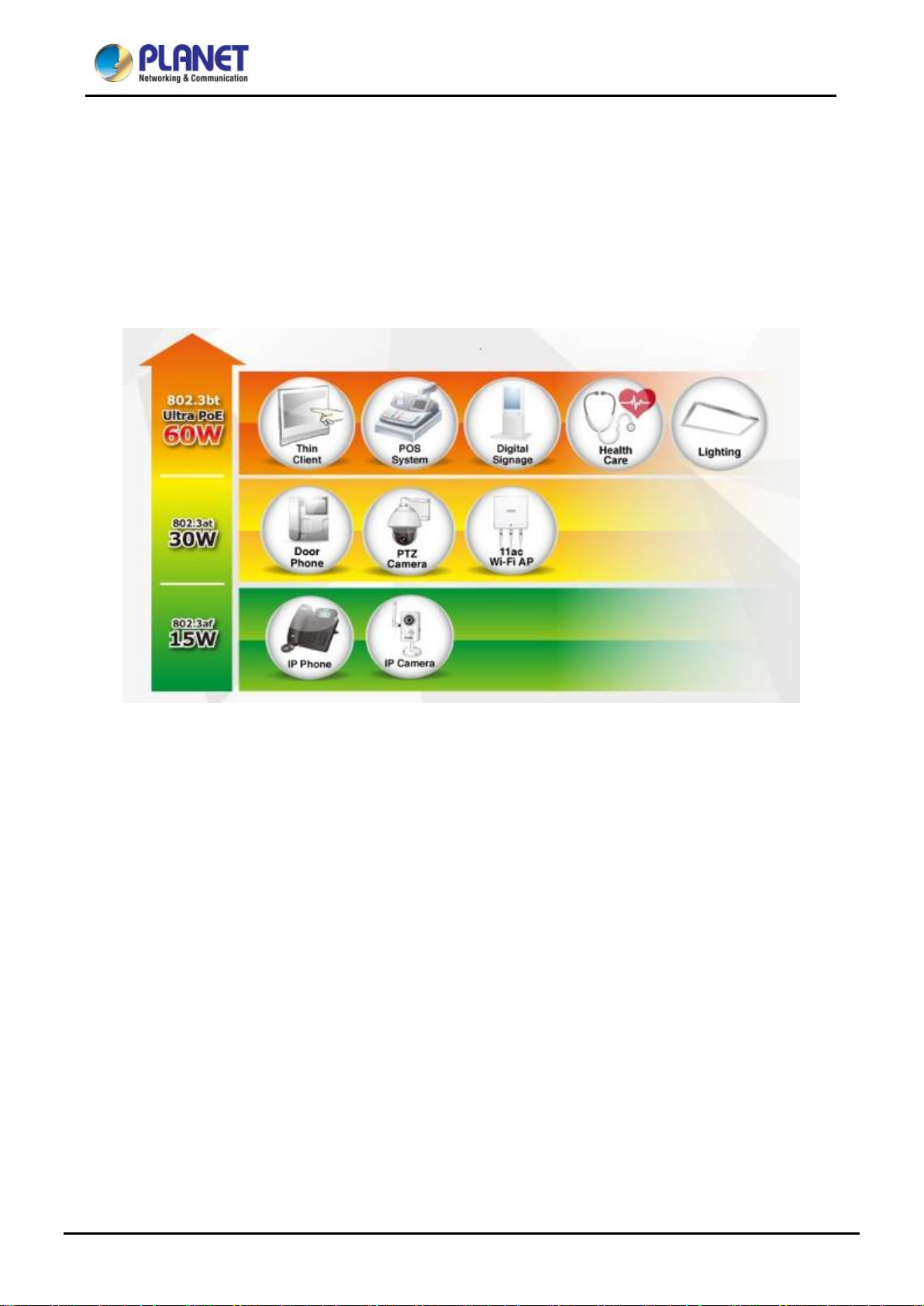
User’s Manual of UPOE-800G/UPOE-1600G/UPOE-2400G
device. It possesses double amount of power capability than the conventional 802.3at PoE and is an ideal solution to
satisfying the growing demand for higher power consuming network PDs, such as:
■ PoE PTZ speed dome
■ Any network device that needs higher PoE power to work normally
■ Thin-client
■ AIO (all-in-one) touch PC, point of sale (POS) and information kiosks
■ Remote digital signage display
Friendly Web Management Interface
To efficiently manage the powered devices, the Ultra PoE Managed Injector Hub provides simple Web mana geme nt
interface in which administrators can control the system and PoE functions for powered devices. It can automat ically
detect the power status of each port and show messages on its Web management interface. These features also provide
users with a cost-effective way to manage the device via Internet whenever they are at work or at home.
7
Page 8
User’s Manual of UPOE-800G/UPOE-1600G/UPOE-2400G
Built-in Unique PoE Functions for Powered Device Management
As it is the Ultra PoE Managed Inje ctor Hub for VoIP, wireles s and surv eillance networ ks, the Ultra PoE Managed Injector
Hub features the following special PoE managem ent fun ctio n s:
PoE schedule
PD alive check
Scheduled power recycling
UPOE, end-span or mid-span selectable in PoE power output mode
PoE usage monitoring
Over temperature protection
8
Page 9
User’s Manual of UPOE-800G/UPOE-1600G/UPOE-2400G
Intelligent Powered Device Alive Check
PLANET’s Managed PoE prod ucts adopt not only Pow er ov er Ether net t echnol ogy, b ut also automate d PD monitori ng and
real-time PoE status. The Ultra PoE M anaged Injec tor Hub can be configured to monitor connected PD ’s statu s in real ti me
via ping action through the uplinked Ethernet switch. Once the PD stops working and responding, the Ultra PoE Managed
Injector Hub will recycle the PoE port power and bring the PD back to work. It also will greatly enhance the network
reliability in that the PoE port will reset the PD power, thus reducing administrator’s management burden.
PoE Schedule for Energy Saving
Under the trend of energy saving worldwide and contributing to environmental protection on the Earth, the Ultra PoE
Managed Injector Hub can effectively control the pow er supply besides it s capability of givin g high w atts power . The built-in
“PoE schedule” function helps you to enable or disable PoE power feeding for each PoE port during specified time
intervals and it is a powerful function to help SMBs or enterprises save power and money. It also increases security by
powering off PDs that should not be in use during non-business hours.
9
Page 10
User’s Manual of UPOE-800G/UPOE-1600G/UPOE-2400G
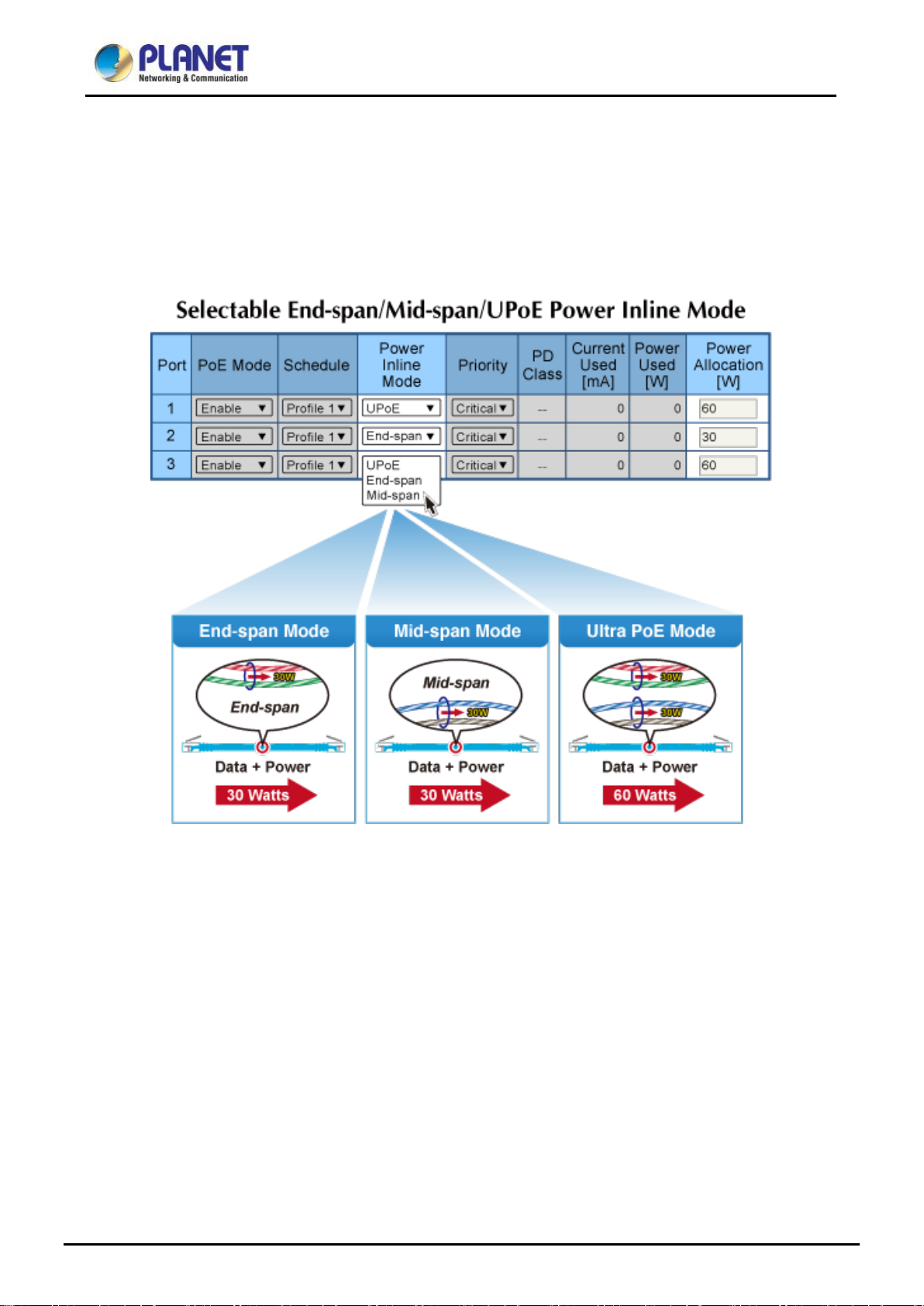
Advanced PoE Power Output Mode Management
To fulfill the demand of various powered devices consuming stable PoE power, the Ultra PoE Managed Injector Hub
provides three different PoE power output modes for selection.
60W UPOE PoE Power Output Mode (Pins 1, 2, 3, 6 + Pins 4, 5, 7, 8)
30W End-span PoE Power Output Mode (Pins 1, 2, 3, 6)
30W Mid-span PoE Power Output Mode (Pins 4, 5, 7, 8)
Advanced Power Management
To facilitate power management, the Ultra PoE Managed Injector Hub comes with powerful PoE management features
such as over temperature protection, usage threshold alert and aut o power alloc ation to prevent power budget
overloading. The PoE power budget can be allocated by priorities or classification and sent alert event logs when power
usage reaches the defined threshold.
10
Page 11
User’s Manual of UPOE-800G/UPOE-1600G/UPOE-2400G
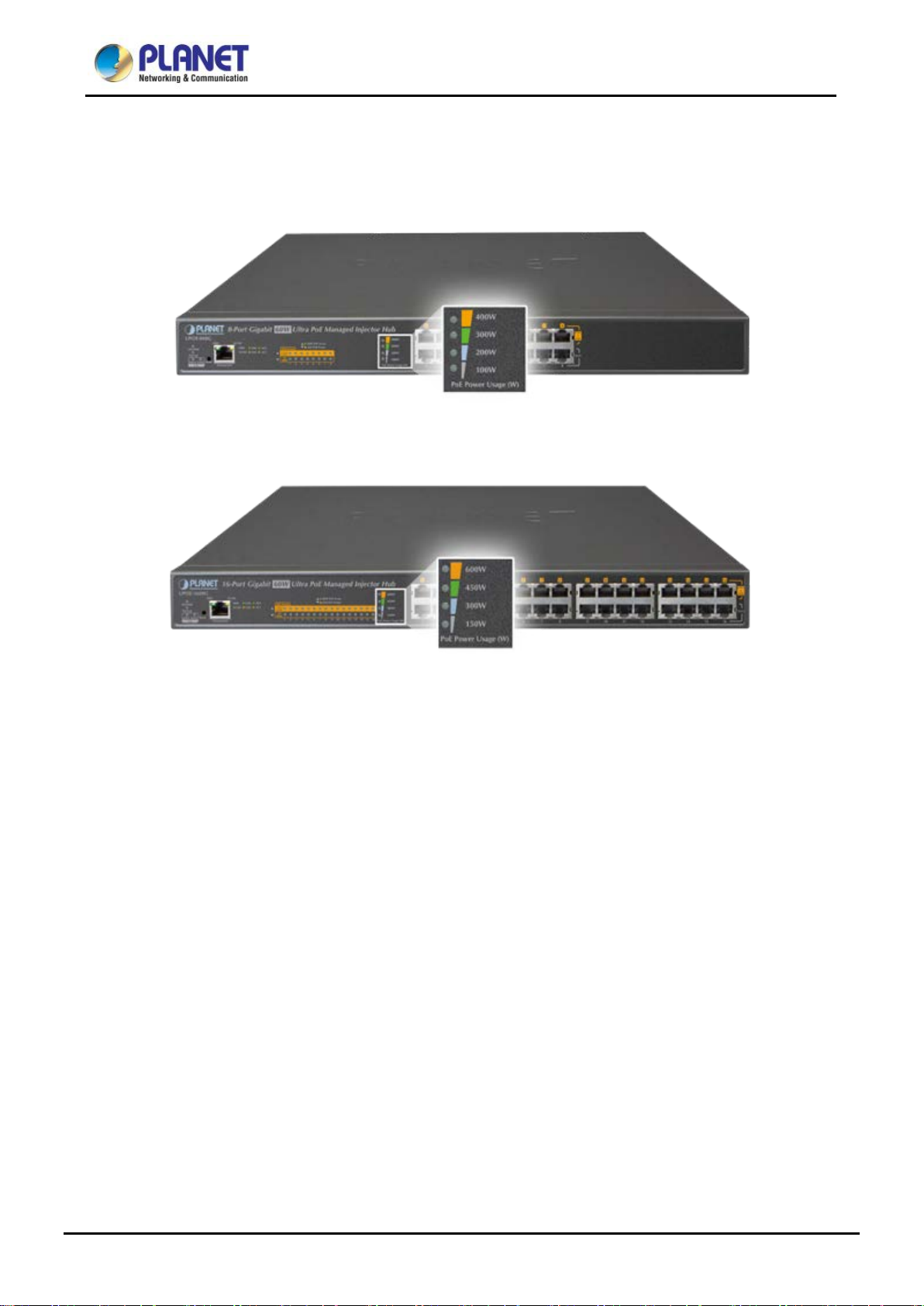
Intelligent LED Indicator for R eal-time PoE Usage
The Ultra PoE M anaged Inj ector Hub helps users to monitor the current status of P oE power usa ge easily and effici ently by
its advanced LED indication. The front panel of the UPOE-800G has four green LEDs indicating 100W, 200W, 300W and
400W of PoE power usage.
The front panel of the UPOE-1600G also has four green LEDs indicating 150W, 300W, 450W and 600W of PoE power
usage.
PoE Usage Monitoring
Via the power usage chart in the web management interface, the Ultra PoE Managed Injector Hub enables the
administrator to monitor the status of the power usage of the connected PDs in real time.
High Power Budget for 802.3at PoE Extension
With IEEE 802.3af/802.3at PoE output capability , the Ultra PoE M anaged Injector Hub can extend much longer distance by
using PLANET PoE Extender for powering up the PoE PD which can be installed over more than 100 meters away. By
daisy-chaining multiple PLANET PoE Extenders, it offers the g reat flex ibility of doubling, tr ipling or qu adrupling the di stance
of PoE network.
Smart Fan Design for Silent Operation
The Ultra PoE M anaged In ject or Hub features a low noise de sign and an effec tive v entilati o n system. It supports the smart
fan technology that automatically contro ls t h e spe ed of the built-in fan to reduce noise and maintain the temperature of the
Ultra PoE Managed Injector Hub for optimal power output capability. The Ultra PoE Managed Injector Hub is abl e to
operate reliably, stably and quietly in any environment without affecting its performance.
11
Page 12

User’s Manual of UPOE-800G/UPOE-1600G/UPOE-2400G
1.3 How to Use This Manual
This User Manual is structured as follows:
Section 2, Installation
It explains the functions of Ultra PoE Managed Injector Hub and how to physically install the Ultra PoE Managed
Injector Hub.
Section 3, Management
It contains information about the software function of the Ultra PoE Managed Injector Hub.
Section 4, Web Configuration
The section explains how to manage the Ultra PoE Managed Injector Hub through Web interface.
Section 5, Power over Ethernet overview
The section explains the Power over Ethernet theories.
Section 6, PoE Power Provision Process
The section explains the PoE power provision process.
Appendix A
It contains cable information of Ultra PoE Managed Injector Hub.
12
Page 13

User’s Manual of UPOE-800G/UPOE-1600G/UPOE-2400G
1.4 Product Features
Interface
UPOE-800G
Complies with the IEEE 802.3, IEEE 802.3u and I EEE 802. 3 ab Ether net sta ndar d s
16-port RJ45
8-port 10/100/1000Mbps “Data input”
8-port 10/100/1000Mbps “Data + Power output”
One 10/100/1000BASE-T management port
UPOE-1600G
Complies with the IEEE 802.3, IEEE 802.3u and IEEE 802.3ab Ethernet standards
32-port RJ45
16-port 10/100/1000Mbps “Data input”
16-port 10/100/1000Mbps “Data + Power output”
One 10/100/1000BASE-T management port
UPOE-2400G
Complies with the IEEE 802.3, IEEE 802.3u and IEEE 802.3ab Ethernet standards
48-port RJ45
24-port 10/100/1000Mbps “Data input”
24-port 10/100/1000Mbps “Data + Power output”
One 10/100/1000BASE-T management port
Power over Ethernet
Ultra Power over Ethernet end-span/mid-span PSE
Up to 60 watts of power on 4-pair UTP
Backward compatible with IEEE 802.3at/af PD device
54V DC, 60-watt PoE power output at maximum on each port, 400-watt PoE budget (UPOE-800G)
52V DC, 60-watt PoE power output at maximum on each port, 600-watt PoE budget (UPOE-1600G)
54V DC, 60-watt PoE power output at maximum on each port, 800-watt PoE budget (UPOE-2400G)
Auto-detection of IEEE 802.3at/af PoE equipment and d ev ice t o av oid po ssibl e damage by incorrect installa t i o n
Circuit protection prevents power interference between ports
Remote power feeding up to 100m
PoE Management
Per port PoE power schedule
PoE function enable/disable
Per port PoE function enable/disable
PoE port power feeding priority
13
Page 14

User’s Manual of UPOE-800G/UPOE-1600G/UPOE-2400G
PD classification detection
Over temperature protection
PD alive check
PoE schedule
Management
Web interface for remote management
Supports Network Time Protocol (NTP)
Firmware upgrade through Web interface
PLANET Smart Discovery utility automatically finds PLANET devices on the network
SNMP trap for alarm notification of events
System log/remote syslog
Hardware
19-inch rack mountable; 1U height
Reset button for resetting to default setting and system reboot
LED indicators for PoE ready and PoE activity
LED indicators for power alert and fan alert
LED indicators for PoE power usage status (watts), UPOE-800G/UPOE-1600G only
FCC Part 15 Class A, CE
14
Page 15
8 x RJ45
16 x RJ45
24 x RJ45
“Data + Power” Output
Ports
1 x RJ45; 10/100/1000BASE-T, auto-negotiation, auto-MDI/MDIX
System: SYS PWR x 1 (green)
100-240V AC,
100-240V AC,
100-240V AC,
520 watts (max.)
800 watts (max)
1000 watts (max.)
440 x 300 x 44.5 mm,
1U height
440 x 300 x 44.5 mm,
1U height
440 x 300 x 44.5
mm, 1U height
Metal
Metal
Metal
IEEE 802.3bt
End-span/Mid-span/UPoE(Ultra PoE)
Pair 1 end-span: 1/2(-), 3/6(+)
DC 54V/60-watt
PoE via 2-pair
DC 52V/60-watt
PoE via 2-pair
DC 54V/60-watt
PoE via 2-pair
(Class 0, 1, 2, 3) can be powered
(Class 0, 4) can be powered
User’s Manual of UPOE-800G/UPOE-1600G/UPOE-2400G
1.5 Product Specificati ons
Product UPOE-800G UPOE-1600G UPOE-2400G
Hardware
“Data” Input Ports
Interface
Management Port
Data Rate
LED
Power Requirements
Power Consumption
Ventilation
Dimensions (W x D x H)
Enclosure
8 x RJ45 16 x RJ45 24 x RJ45
10/100/1000Mbps
PoE Failure x 1 (red)
Fan Failure x 2 (red)
Management port x 2: 1000 (green), 10/100(orange)
Per PoE Port: Ultra 60W PoE-in-use x 1 (green)
802.3at/af PoE-in-use x1 (orange)
PoE Power Usage LED x4 (green), UPOE-800G/UPOE-1600G only
50/60 Hz, 6.5A
/ 1774BTU
Fan x 3 Fan x 3 Fan x 3
50/60 Hz, 8A
/ 2729BTU
50/60 Hz,15A
/ 3412BTU
Weight
Power over Ethernet
PoE Standard
PoE Power Supply Type
Power Pin Assignment
PoE Power Output
PoE Power Budget 400 watts/1364BTU 600 watts/2047BTU 800 watts/2729BTU
Number of 60W PDs can be powered 6 10 13
Number of 802.3af PDs
Number of 802.3at PDs
(Class 1, 2, 3) can be powered
Number of 802.3at PDs
4.2kg 4.8kg 5.5kg
IEEE 802.3at Power over Ethernet Plus
4-pair Ultra PoE
Pair 2 mid-span: 4/5(+), 7/8(-)
UPoE: 1/2(-), 3/6(+),4/5(+), 7/8(-)
PoE via 4-pair
DC 54V/30-watt
8 16 24
8 16 24
8 16 24
PoE via 4-pair
DC 52V/30-watt
PoE via 4-pair
DC 54V/30-watt
15
Page 16

Power limit by consumption and allocation
Setup of system/manage men t funct ion s
IEEE 802.3 10BASE-T Ethernet
10BASE-T: 4-pair UTP Cat5 up to 100m (328ft)
Temperature: -10 ~ 70 degrees C
User’s Manual of UPOE-800G/UPOE-1600G/UPOE-2400G
Management
Management Interface Web, PLANET Smart Discovery Lite
PoE admin mode
Per port power schedule
Per port power enable/disable
PoE Management
Management Feature
Standards Conformance
Regulatory Compliance FCC Part 15 Class A, CE
Power feeding priority
Over temperature protection
Current per port usage and status
Total power consumption
PD alive check
Scheduled power recycling
Web firmware upgrade
SNMP trap for alarm notification of events
IEEE 802.3u 100BASE-TX Fast Ethernet
IEEE 802.3ab 1000BASE-T Gigabit Ethernet
IEEE 802.3at Power over Ethernet Plus
IEEE 802.3af Power over Ethernet
Standards Compliance
Network Cable
Environments
Operating
Storage
RFC 768: UDP
RFC 791: IP
RFC 2068 HTTP
RFC 1157: SNMP v1
RFC 1902: SNMP v2c
RFC 5424: Syslog
100BASE-TX: 4-pair UTP Cat5 up to 100m (328ft)
1000BASE-T: 4-pair UTP Cat5e/6 up to 100m (328ft)
EIA/TIA- 568 100-ohm STP (100m)
Temperature: 0 ~ 50 degrees C
Relative Humidity: 5 ~ 90% (non-condensing)
Relative Humidity: 5 ~ 90% (non-condensing)
16
Page 17
User’s Manual of UPOE-800G/UPOE-1600G/UPOE-2400G
2. INSTALLAT I ON
This section describes the hardware features and installation of Ultra PoE Managed Injector Hub on the desktop or rack
mount. For easier management and control of the Ultra PoE Managed Injector Hub, familiarize yourself with its display
indicators, and ports. Fro nt panel illustrati ons in this chapt er display the unit LED indicators. Before deploying the Ultra PoE
Managed Injector Hub, please r ead this chapter co mpl etely .
2.1 Hardware Description
The section describes the hardware of the Ultra PoE Managed Injector Hub and gives a physical and functional overview.
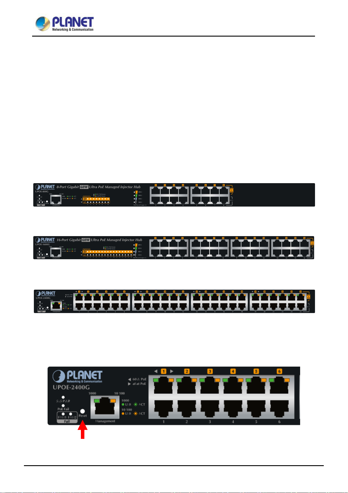
2.1.1 Injector Front Panel
The unit front panel provides a simple interface monitoring the Ultra PoE Managed Injector Hub. Figures 2-1-1, 2-1-2 and
2-1-3 show the front panels of the Ultra PoE Managed Injector Hubs.
Front Panel of UPOE-800G
Figure 2-1-1: UPOE-800G Front Panel
Front Panel of UPOE-1600G
Figure 2-1-2: UPOE-1600G Front Panel
Front Panel of UPOE-2400G
Figure 2-1-3: UPOE-2400G Front Panel
■ Reset button
At the left of the front panel, the reset button is designed for rebooting the Ultra PoE Managed Injector Hub without
turning off and on the power.
Figure 2-1-4: Reset Button of Ultra PoE Managed Injector Hub
17
Page 18
Reset Button Pressed and Released
Function
will reboot
and load the default IP settings.
else the entire configuration will be erased when
LED
Color
Function
LED
Color
Function
User’s Manual of UPOE-800G/UPOE-1600G/UPOE-2400G
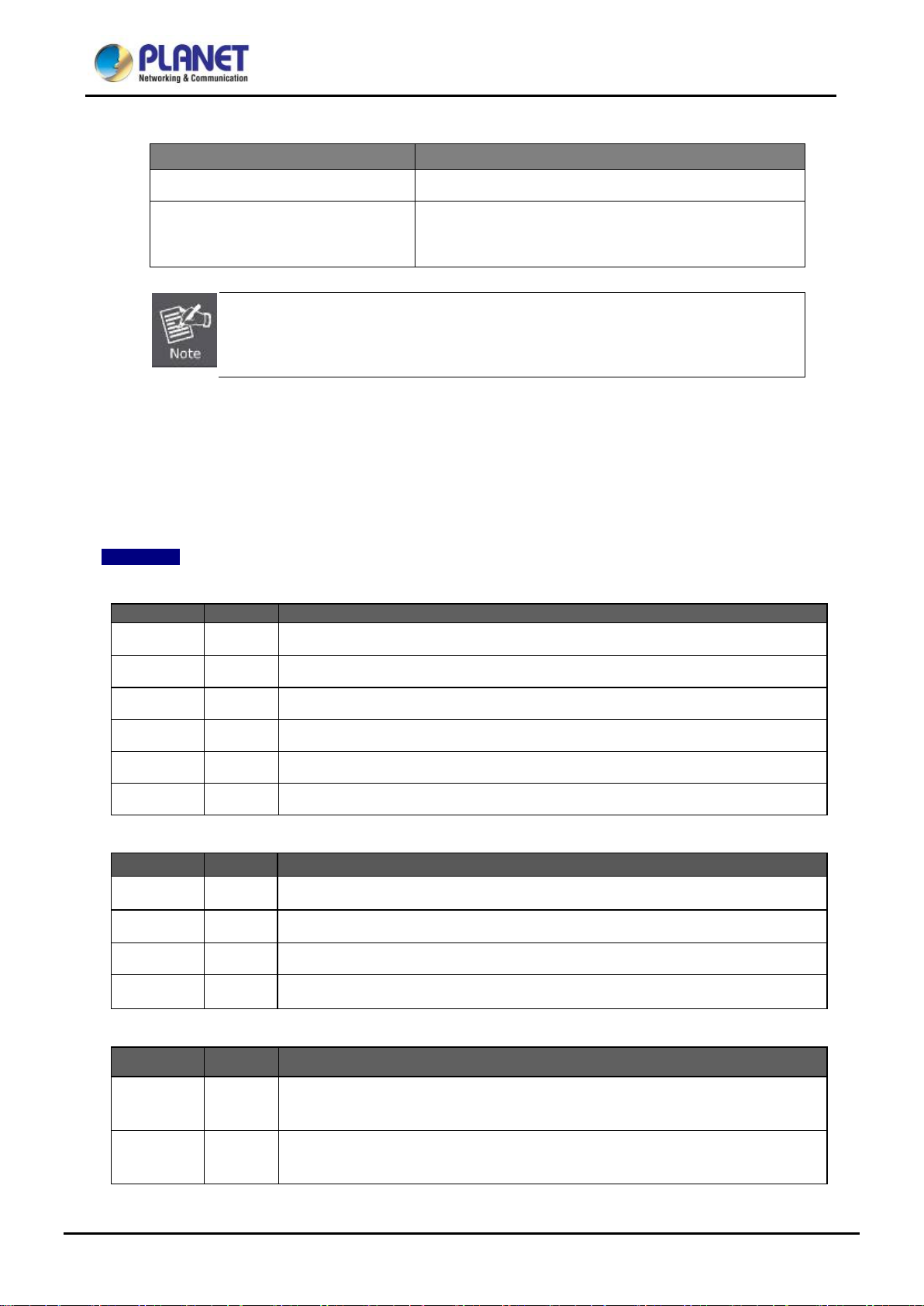
The following is the summary table of reset button funct ion s:
About 5 second Reboot the Ultra PoE Managed Injector Hub.
Reset the Ultra PoE Managed Injector Hub to Fact ory Defau lt
About 10 seconds
Be sure that you back up the current configuratio n of Ultra PoE Managed Injector Hub before
resetting Ultra PoE Managed Injector Hub or
pressing the “RESET” button.
configuration. The Ultra PoE Managed Injector Hub
2.1.2 LED Indicators
The front panel LEDs indicates instant status of system power, PoE and fan failure, management port speed and
Link/Active, PoE pow er us age status and per PoE port links status, thus helping administrat or to m onitor and troubleshoo t
when needed.
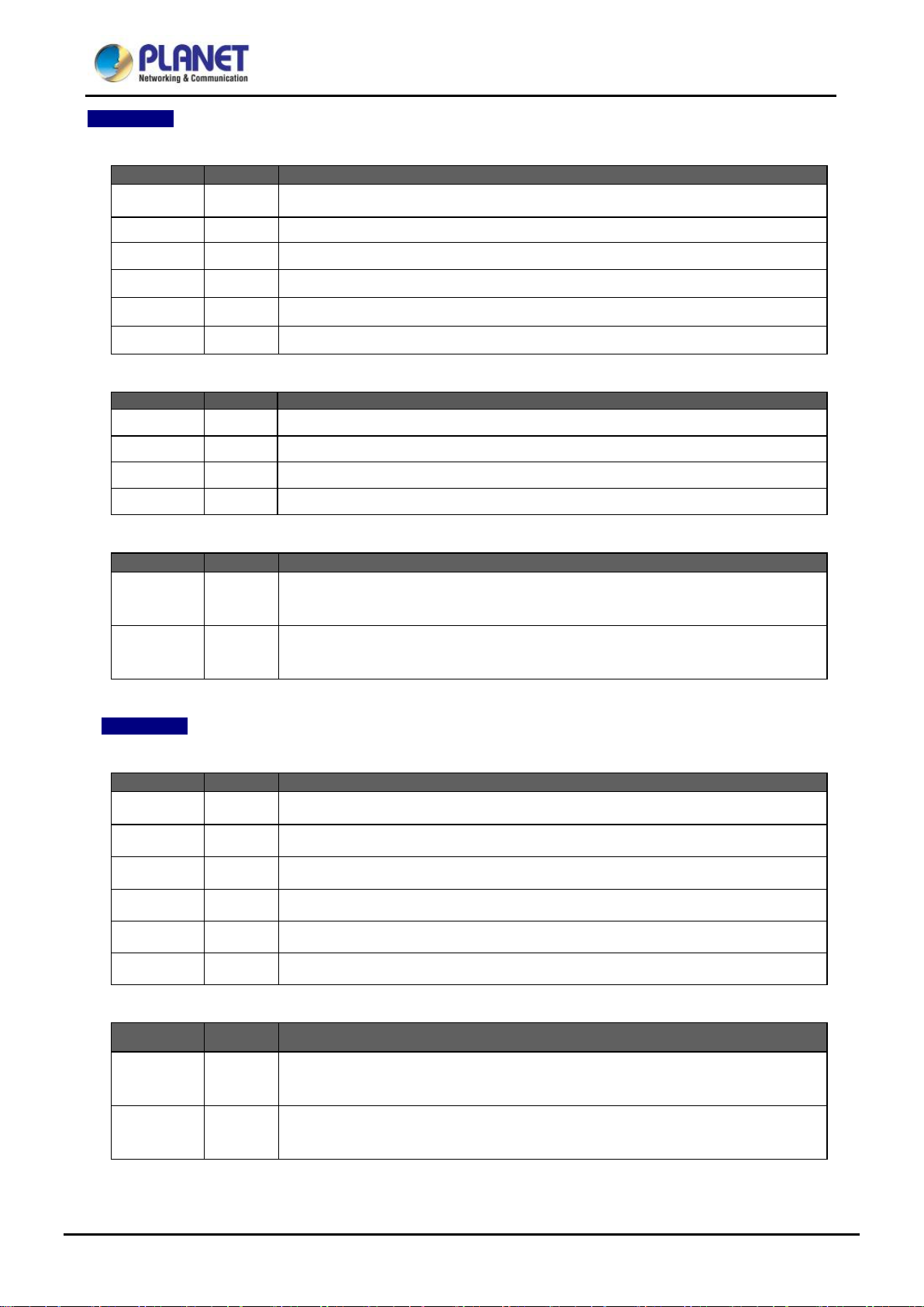
UPOE-800G
■ System
SYS Power Green Lights to indicate power on.
PoE Fail Red Lights to indicate PoE module failure.
FAN1 Fail
FAN2 Fail
1000 Green Lights to indicate management port is working on 1000Mbps Ethernet speed.
10/100 Orange Lights to indicate management port is working on 10/100Mbps Ethernet speed.
■ PoE Power Usage (W)
100W
200W
300W
400W
■ Per PoE Port:
Red
Red
Green
Green
Green
Green
Lights to indicate FAN1 stops.
Lights to indicate FAN2 stops.
Lights to indicate the PoE power consumption has 100W or over.
Lights to indicate the PoE power consumption has 200W or over.
Lights to indicate the PoE power consumption has 300W or over.
Lights to indicate the PoE power consumption has 400W.
LED Color Function
Ultra 60W
PoE-in-Use
802.3at/af
PoE-in-Use
Green Lights to indicate that the port is in use and supplying 54V DC power.
Orange Lights to indicate that the port is in use and supplying 54V DC power.
18
Page 19
LED
Color
Function
LED
Color
Function
150W
Lights to indicate the PoE power consumption has 150W or over.
300W
Lights to indicate the PoE power consumption has 300W or over.
450W
Lights to indicate the PoE power consumption has 450W or over.
600W
Lights to indicate the PoE power consumption has 600W.
LED
Color
Function
LED
Color
Function
User’s Manual of UPOE-800G/UPOE-1600G/UPOE-2400G
UPOE-1600G
■ System
SYS Power Green Lights to indicate power on.
PoE Fail Red Lights to indicate PoE module failure.
FAN1 Fail Red Lights to indicate FAN1 stops.
FAN2 Fail Red Lights to indicate FAN2 stops.
1000 Green Lights to indicate management port is working on 1000Mbps Ethernet speed.
10/100 Orange Lights to indicate management port is working on 10/100Mbps Ethernet speed.
■ PoE Power Usage (W)
Green
Green
Green
Green
■ Per PoE Port:
Ultra 60W
PoE-in-Use
802.3at/af
PoE-in-Use
UPOE-2400G
■ System
SYS Power Green Lights to indicate power on.
PoE Fail Red Lights to indicate PoE module failure.
FAN1 Fail
FAN2 Fail
1000 Green Lights to indicate management port is working on 1000Mbps Ethernet speed.
10/100 Orange Lights to indicate management port is working on 10/100Mbps Ethernet speed.
Green Lights to indicate that the port is in use and supplying 52V DC power.
Orange Lights to indicate that the port is in use and supplying 52V DC power.
Red
Red
Lights to indicate FAN1 stops.
Lights to indicate FAN2 stops.
■ Per PoE Port:
LED Color Function
Ultra 60W
PoE-in-Use
802.3at/af
PoE-in-Use
Green Lights to indicate that the port is in use and supplying 54V DC power.
Orange Lights to indicate that the port is in use and supplying 54V DC power.
19
Page 20

E Managed Injector
will not work till it is powered. If your networks should be active all the time, please consider using
UPS (Uninterrupted Power Supply ) for y our devi ce. It w ill pr ev ent you from n etw ork data loss or netw ork
from being
User’s Manual of UPOE-800G/UPOE-1600G/UPOE-2400G
2.1.3 Injector Rear Panel
The rear panel of the U ltra Po E M anaged Inj ector Hub indicates an AC inlet power socket, w hich accept s input power from
100 to 240V AC, 50/60Hz. Figures 2-1-5 & 2-1-6 shows the rear panel of the Ultra PoE Managed Injector Hub.
Figure 2-1-5: UPOE-800G/UPOE-1600G Rear Panel
Figure 2-1-6: UPOE-2400G Rear Panel
The Ultra PoE Managed Injector Hub is a power-required device, meaning Ultra Po
Hub
downtime.
In some areas, installing a surge suppression device may also help to protect your device
damaged by unregulated surge or current to the Ultra PoE Managed Injector Hub or the power adapter.
2.2 Installing the Ultra PoE Managed Injector Hub
This section describes how to install your Ultra PoE Managed Injector Hub and make connections to the Ultra PoE
Managed Injector Hub. Please read the follow ing topics and p erform the pr ocedure s in the order b eing prese nted. PLANET
Ultra PoE Managed Injector Hub does not need software configuration.
2.2.1 Desktop Installation
To install an Ultra PoE Managed Injector Hub on a desktop or shelf, simply complete the following steps:
Step 1: Attach the rubber feet to the recessed areas on the bottom of the Ultra PoE Managed Injector Hub.
Step 2: Place the Ultra PoE Managed Injector Hub on a desktop or shelf near an AC power source.
Step 3: Keep enough ventilation space between the Ultra PoE Managed Injector Hub and the surroundin g objects.
20
Page 21

iscussed in Chapter
User’s Manual of UPOE-800G/UPOE-1600G/UPOE-2400G
Figure 2-2-1: Desktop Installation of the Ultra PoE Managed Injector Hub
When choosing a location, please keep in mind the environmental restrictions d
1, Section 5, under Specifications.
Step 4: C onnect y our Ultra P oE M anaged Inje ctor Hub to network 60 W/802.3at/802.3af pow ered device s (PD) an d Switc h.
A. Connect one end of a standard network cable to the u pper stack 10 /100/1000 R J45 ports on the front of the Ultra
PoE Managed Injector Hub.
B. Connect the other end of the cable to the 60 W/802.3at/802. 3af powered dev ices (PD) such as IP pho ne, wireles s
access point, IP camera, splitter, or switch etc.
C. Connect one end of a standard network cable to the relative lower stack 10/100/1000 RJ45 port on the front of
the Ultra PoE Managed Injector Hub.
D. Connect the other end of the cable to the port of Switch.
Connecting to the Ultra PoE Managed Injector Hub requires UTP Category 5e / 6 network cabl ing
with RJ45 tips. For more information, please see the Cabling Specification in Appendix A.
Step 5: Supplying Power to the Ultra PoE Managed Injector Hub.
A. Connect one end of the power cable to the Ultra PoE Managed Injector Hub.
B. Connect the power plug of the power cable to a standard wall outlet.
When the Ultra PoE Managed Injector Hub receives power, the Power LED should remain solid Green.
2.2.2 Rack Mounting
To install the Ultra PoE Managed Injector Hub in a 19-inch standard rack, follow the instructions described below.
Step 1: Place your Ultra PoE Managed Injector Hub on a hard flat surface, with the front panel positioned towards your
front side.
Step 2: Attach a rack-mount bracket to each side of the Ultra PoE Manage d Injector Hub w ith supp lied scr ew s attached t o
the package. Figure 2-2-2 shows how to attach brackets to one side of the Ultra PoE Managed Injector Hub.
21
Page 22

You must use the screws supplied with the mounting brackets. Damage caused to the parts by
User’s Manual of UPOE-800G/UPOE-1600G/UPOE-2400G
Figure 2-2-2: Brackets attaching to the Ultra PoE Managed Injector Hub
using incorrect screws would invalidate the warranty.
Step 3: Secure the brackets tightly.
Step 4: Follow the same steps to attach the second bracket to the opposite side.
Step 5: After the brackets are attached to the Injector, use suitable screws to securely attach the brackets to the rack, as
shown in Figure 2-2-3.
Figure 2-2-3: Mounting the Ultra PoE Managed Injector Hub in a Rack
Step 6: Proceed with steps 4 and 5 of session 2.2.1 Desktop Installation to connect the network cabling and supply
power to your Ultra PoE Managed Injector Hub.
22
Page 23

User’s Manual of UPOE-800G/UPOE-1600G/UPOE-2400G
2.2.3 Network Application Installation
The Ultra PoE Managed Injector Hub is not an equipment with data switching function between data ports. To inject PoE
power and transmit data packets to PDs, the Ultra PoE Managed Injector Hub is usually linked to an Ethernet switch.
Typically, the Ultra PoE Injector is installed between regular Ethernet switch and PDs, and mostly it is located close to the
Ethernet switch side.
To install an Ultra PoE Managed Injector Hub on a network environment, simply complete the following steps:
Step 1: Power on the Ultra PoE Managed Injector Hub and connect the RJ45 cable from the “Data” port to the Ethernet
switch port.
Step 2: Connect the RJ45 cable from the “Data + Power” ports to the PDs, such as VoIP phone and IP camera.
Step 3: Check the link statu s on both PD an d Ethernet switch. O nce the Injector starts to d eliver 52V/54V power over RJ45
cables to PDs, the PoE-in-Use LED of the Ultra PoE Managed Injector Hub will light up.
Figure 2-2-4: Network application ins tall ati on
The Ultra PoE Managed Injector Hub supports data passive mode, that is, even the Ultra PoE Managed Injector Hub is
manually powered off. The data between “DATA” port and “DATA & PWR” port can still be tran smitted w itho ut data los s.
23
Page 24

can install IP
High Power Speed Dome
User’s Manual of UPOE-800G/UPOE-1600G/UPOE-2400G
2.2.4 Power over Ethernet Powered Device
Voice over IP phones
Enterprise can install PoE VoIP Phone, ATA and other
3~5 watts
6~12 watts
10~12 watts
Ethernet/non-Ethernet end-devices in the central area where UPS is
installed for un-interruptible power system and power control system.
Wireless LAN Access Points
Museums, sightseeing spots, airports, hotels, campuses, factories, and
warehouses can install the Access Point anywhere.
IP Surveillance
Enterprises, museums, campuses, hospitals and banks
camera without the limit of the installation location. Electrician is not needed
to install AC sockets.
PoE Splitter
3~60 watts
30~60 watts
Since the Ultra PoE Managed Injector Hub per PoE port supports 52V (UPOE-1600G) or 54V DC
(UPOE-800G/UPOE-2400G) PoE power output, please che ck and assure the P owered De vice’s (PD)
acceptable DC pow er is 52V (UPOE-1600G) and 54V DC (UPOE-800G/UPOE-2400G); otherwise, it
will damage the Powered Device (PD).
PoE Splitter splits the PoE DC over the Ethernet cable into 5/12/19/24V DC
power output. It frees the device deployment from restrictions due to power
outlet locations, which eliminate the costs for addition al AC wiring and
reduces the installation time.
This state-of-the-art design is considerabl e to fit in various n et w or k
environments like traffic centers, shopping malls, railway stations,
warehouses, airports, and production facilities for the most demanding
outdoor surveillance applications. Electrician is not needed to install AC
sockets.
24
Page 25

Ultra PoE Managed
not accessible,
User’s Manual of UPOE-800G/UPOE-1600G/UPOE-2400G
3 MANAGEMENT
This chapter describes how to manage the Ultra PoE Managed Injector Hub with the following topics included:
- Overview
- Management Method
- Logging on to the Ultra PoE Managed Injector Hub
3.1 Overview
The Ultra PoE Managed Injector Hub provides a user-friendly, Web interface where you can perform various device
configuration and management activities, including:
System
SNMP
Power over Ethernet
3.2 Requirements
■ Network cables
Use standard network (UTP) cables with RJ45 connectors.
■ Workstations running Windows XP/2003/Vista/7/8/2008/10, MAC OS X or later, Linux, UNIX, or other platforms
are compatible with TCP/IP protocols.
■ Workstations are installed with Ethernet NIC (Network Interface Card)
Ethernet Port Connection
■ Network cables -- Use standard network (UTP) cables with RJ45 connectors.
■ The above PC is installed with Web browser and JAVA runtime environment plug-in.
It is recommended to use Internet Explorer 11 or above to access the
Injector Hub. If the Web interface of the Ultra PoE Managed Injector Hub is
please turn off the anti-virus software or firewall and then try it again.
25
Page 26

User’s Manual of UPOE-800G/UPOE-1600G/UPOE-2400G
3.3 Management Method
User can manage the Ultra PoE Managed Injector Hub by Web Management via a network connection.
3.3.1 Web Management
The Ultra PoE Managed Injector Hub c an be con fig ur ed t hrough an Ethernet connect ion. T he fa ctor y def ault IP addr es s i s
192.168.0.100 w ith subnet mask 255.255.255.0, so please make sure the manager PC mus t be set to the same IP sub ne t
address. For example, if Ultra PoE Managed Injecto r Hub IP address is set to factory default, then your manager PC
should be set to 192.168.0.x (w her e x is a number between 1 and 254, except 10 0) with a subnet mask of 255.255.255.0.
1. Use Internet Explorer 8.0 or above Web browser. Enter IP address http://192.168.0.100 to access the Web interface.
Figure 3-1-1: IP Management Diagram
2. When the following login screen appears, please enter the default u sername "admin" and password “admin” to login
the main screen of Ultra PoE Managed Injector Hub. The login screen in Figure 3-1-2 appears.
Default IP Address: 192.168.0.100
Default Account: admin
Default Password: admin
Figure 3-1-2: Ultra PoE Managed Injector Hub Web Login Screen
26
Page 27

If there are two LAN cards or abov e in the same a dmini strat or P C, choos e a diff erent LAN ca rd by us ing
User’s Manual of UPOE-800G/UPOE-1600G/UPOE-2400G
1. For security reason, please change and memorize the new password after this first setup.
2. Only accept command in lowercase letter under Web interface.
3.3.2 PLANET Smart Discovery Utility
For easily listing the Ultra PoE Managed Injector Hub in your Ethernet environment, Planet Smart Discovery Utility from
user’s manual CD-ROM is an ideal solution.
The following installation instructions guide you to running Planet Smart Discovery Utility.
Deposit Planet Smart Discovery Utility in administrator PC.
Run this utility and the following screen appears.
Figure 3-1-3: Planet Smart Discovery Utility Screen
the “Select Adapter” tool.
27
Page 28

User’s Manual of UPOE-800G/UPOE-1600G/UPOE-2400G
1. Press the “Refresh” button f or the currently-connected devices in the discovery list and the screen is shown as
follows:
Figure 3-1-4: Planet Smart Discovery Utility Screen
This utility shows all necessary information from the devices, such as MAC address, device name, firmware version and
device IP subnet address. It can also assign new password, IP subnet address and description of the devices.
After setup is completed, press the “Update Device”, “Update Multi” or “Update All” button to take effect. The
definitions of the 3 buttons above are shown below:
Update Device: Use current settin g on one single devi ce.
Update Multi: Use current setting on multi-devices.
Update All: Use current setting on whole devices in the list.
The same functions mentioned above also can be found in “Option” tools bar.
By clicking the “Control Packet Force Broadcast” function, it allows you to assign new setting value to the Ultra PoE
Managed Injector Hub under a different IP subnet address.
Press the “Connect to Device” button and then the Web login screen appears in Figure 3-1-2.
Press the “Exit” button to shut down Planet Smart Discovery Utility.
28
Page 29

Provides System information of Ultra PoE Managed Injector Hub. Explained in
section 4.3.
Provides SNMP Trap information and system information. Explained in section
Explained in section 4.5.
User’s Manual of UPOE-800G/UPOE-1600G/UPOE-2400G
4 WEB CONFIGURATION
The Ultr a PoE Managed Injec tor Hub provides Web interface for PoE smart function conf iguration and makes the Ultra PoE
Managed Injector Hub operate more effectively. They can be configured t hrough the Web browser. A netw ork administrato r
can manage and monitor the Ultra PoE Managed Injector Hub from the local LAN. This section indicates how to configure
the Ultra PoE Managed Injector Hub to enable its smart functi on.
The following web screen is b ased on t he UPO E-2400G. T he display of t he UPOE -800G and UPOE-1600G
is the same as that of the UPOE-2400G.
4.1 Main Menu
After a successful log in, the main screen a ppears. The main scre en, as shown in Figure 4-1-1, displays the product name,
the function menu, and the main information in the center.
Figure 4-1-1: Web Main Menu screen
The descriptions of the four items are as follows:
Object Description
System
SNMP
Power over Ethernet
4.4.
Provides PoE Management configuration of Ultra PoE Managed Injector Hub.
29
Page 30

Object
Description
Subnet Mask, Gateway and Description. Explained in section 4.3.1.
Explained in section 4.3.2.
NTP server. Explained in section 4.3.3.
Hub. Explained in section 4.3.4.
User’s Manual of UPOE-800G/UPOE-1600G/UPOE-2400G
4.2 Web Panel
At the top of the Web management page, the active panel displays the link status of management port and PoE ports.
Figure 4-2-1: Web Panel Screen
Green light indicates network data is sending or receiving.
Orange light indicates the PoE is in use.
4.3 System
The System function provides system information which also allows user to manage the Ultra PoE Managed Injector Hub
system as Figure 4-2-2 is sho w n below :
Figure 4-2-2: System Function Menu
The page includes the following information:
• System Information
• IP Configuration
• NTP Configuration
• Password Setting
30
Display the MAC address, Software Version, Hardware Version, IP Address,
Allow to change the IP subnet address of Ultra PoE Managed Injector Hub.
Allow to set system time by manual or synchronize system time from Internet
Allow to change the username and password of Ultra PoE Managed Injector
Page 31

Firmware Upgrade
Explained in section 4.3.5
Factory Default
Allow to reset system to factory default setting. Explained in section 4.3.7.
Allow to enable system log and to record system log. Explained in section
4.3.8.
Object
Description
Displays the current syste m da te of Ultra PoE M anaged Inje ctor Hub. T he sys tem
Internet.
User’s Manual of UPOE-800G/UPOE-1600G/UPOE-2400G
•
• Configuration Setting Allow to back up or restore system configuration. Explained in section 4.3.6.
•
• System Log
• System Reboot Allow to reboot system. E xp la ined in secti on 4.3.9.
Allow to upgrade the latest firmware in the future.
.
4.3.1 System Information
This section displays system information of Ultr a PoE Managed Injector Hub as t he s creen in Figure 4-3-1 appears. Table
4-3-1 describes the system information of the Ultra PoE Managed Injector Hub.
Figure 4-3-1: System Information Web Page Screen
• System Name Displays the Ultra PoE Managed Injector Hub model name.
• MAC Addre s s Displays the MAC address of Ultra PoE Managed Injector Hub.
• Software Version Displays the current firmware version of Ultra PoE Managed Injector Hub.
• Build Time Displays the firmware build time.
• Hardware Version Displays the hardware version of Ultra PoE Managed Injector Hub.
• Attain IP Protocol Displays the currently attained IP protocol of Ultra PoE Managed Injector Hub.
• IP Address Displays the current IP address of Ultra PoE Managed Injector Hub.
• Subnet Mask Displays the current subnet mask address of Ultra PoE Managed Injector Hub.
• Gateway Displays the current gateway address of Ultra PoE Managed Injector Hub.
• System Date
date will be correct if NTP function is enabled and the Hub is connected to
• System UpTime Displays when the system will start up.
Table 4-3-1: Descriptions of the System Information Objects Screen
31
Page 32

Injector Hub.
ery Utility to
User’s Manual of UPOE-800G/UPOE-1600G/UPOE-2400G
4.3.2 IP Configuration
This section provides the IP Conf iguration of Ultra PoE Managed Injector Hub as the screen in Figure 4-3-2 appears. Table
4-3-2 describes the IP Configuration object of Ultra PoE Managed Injector Hub.
Figure 4-3-2: IP Configuration Web Page Screen
Object Description
• DHCP Client
• IP Address
• Subnet Mask
• Default Gateway
• Apply
• Reset
Table 4-3-2: Descriptions of the IP Configuration Objects Screen
If Ultra PoE Managed Injector Hub has not received IP address from DHCP server, then user still can
connect to the IP address before changing to DHCP client mode, or user can use Smart Discov
find out what IP address set in the Ultra PoE Managed Injector Hub is currently.
Allows to disable or enable the DHCP Client function of Ultra PoE Managed
Allows to input new IP Address of Ultra PoE Managed Injector Hub.
Allows to input new Subnet Mask Address of Ultra PoE Managed Injector Hub.
Allows to input new Default Ga teway Address of U ltra PoE Managed I njector Hub.
Press this button to take effect.
Press this button to reset IP Configuration to default mode.
32
Page 33

User’s Manual of UPOE-800G/UPOE-1600G/UPOE-2400G
4.3.3 NTP Configuration
This section prov ides the NT P Configur ation of Ultra PoE Managed Injector Hu b as the screen in Figure 4-3-3 appears and
Table 4-3-3 describes the NTP Configuration object of Ultra PoE Managed Injector Hub.
Figure4-3-3: NTP Configuration Web Page Screen
Object Description
• Current Time
• Enable NTP Client Update
• Time Zone Select
• NTP Server
• Apply
• Refresh
Table 4-3-3: Descriptions of the NTP Configuration Web Page Screen Objects
Allow input current time information of Ultra PoE Managed Injector Hub.
Allow disable or enable time update from NTP server of Ultra PoE Managed
Injector Hub.
Allow select the time zone according to current location of Ultra PoE Managed
Injector Hub.
Allow choose one list NTP server or assign one NTP server IP address manually
for Ultra PoE Managed Injector Hub.
Press this button to take effect.
Press this button to refresh the current Web page.
33
Page 34

User’s Manual of UPOE-800G/UPOE-1600G/UPOE-2400G
4.3.4 Password Setting
This section provides the Password Setting of Ultra PoE Managed Injector Hub as the screen in Figure 4-3-4 appears.
Table 4-3-4 describes the Password Setting objects of Ultra PoE Managed Injector Hub.
Figure 4-3-4: Password Setting Web Page Screen
Object Description
• User Name
• Old Password
• New Passwor d
• Confirmed Password
• Apply
• Reset
Table 4-3-4: Descriptions of the Password Setting Objects Screen.
1. For security reason, please change and memorize the new password after this first setup.
2. The maximum length is 15 characters.
Allows to input current User Name of Ultra PoE Managed Injector Hub.
Allows to input current Password of Ultra PoE Managed Injector Hub.
Allows to input new Password of Ultra PoE Managed Injector Hub.
Allows to input new Password again for confirmation of Ultra PoE Managed
Injector Hub.
Press this button to take effect.
Press this button to reset password setting to default mode.
34
Page 35

nd system will reboot automatically.
User’s Manual of UPOE-800G/UPOE-1600G/UPOE-2400G
4.3.5 Firmware Upgrade
This section provides the firmware upgrade of Ultra PoE Managed Injector Hub as the screen in Figure 4-3-5 appears.
Figure 4-3-5: Firmware Upgrade Web Page Screen
Please press “Browse” to locate the latest firmware of Ultra PoE Managed Injector Hub that deposits in your PC. The
screen in Figure 4-3-6 appears.
Figure 4-3-6: Firmware Upgrade Web Page Screen
Press “Upgrade” to start the firmware upgrade process as the screen in Figure 4-3-7 appears.
Figure 4-3-7: Firmware Upgrade Web Page Screen
1. The firmware upgrade process needs 97 seconds to complete a
After the Ultra PoE Managed Injector Hub power on is completed, the latest firmware can be used.
2. Please do not power off the Ultra PoE Managed Injector Hub during firmware upgrade process.
35
Page 36

User’s Manual of UPOE-800G/UPOE-1600G/UPOE-2400G
4.3.6 Configuration Setting
This function allows output the current Ultra PoE Managed Injector Hub config urat ion as a fi le, and uplo ad it to other Ultra
PoE Managed Injector Hub for quick multi-devices setting. The description of the procedure and screens in the following
appears. The screen in Figure 4-3-8 appears and Table 4-3-5 describes the Configuration Setting object of Ultra PoE
Managed Injector Hub.
Figure 4-3-8: Configuration Backup Screen
Object Description
• Save Settings to File
• Load Settings form File
• Browse…
• Upload
Table 4-3-5: Descriptions of the Configuration Setting Objects Screen
■ Configur ation Download
All current configurations (except IP Configuration) will output as a configuration file once the “Save” button is pressed.
Save the current configuration in manager workstation and the screen in Figure 4-3-9 to Figure 4-3-11 appears.
Allow to save system configuration t o a file an d download to m anager workstat ion.
Allow to restore system configuration to Ultra PoE Managed Injector Hub.
Allow to specify the system configuration file locate path.
Upload system configuration file to Ultra PoE Managed Injector Hub.
Figure 4-3-9: File Download Screen
36
Page 37

User’s Manual of UPOE-800G/UPOE-1600G/UPOE-2400G
Figure 4-3-10: File Save Screen
■ Configur ation Upload
Click the “Browse” butt on of t he Con figurat ion Setting Web page and the system w ould po p up the fi le select ion screen to
choose saved configuration. The screen in Figure 4-3-11 appears.
Figure 4-3-11: Windows File Selection Screen
37
Page 38

User’s Manual of UPOE-800G/UPOE-1600G/UPOE-2400G
Select on the configuration file and then click “Upload”. After system h as upl oaded, the screen in Figure 4-3-12 appears.
Figure 4-3-12: Configuration U pload Fin ish ed Screen
When configuration has been uploaded, please re-login the system.
Figure 4-3-13: System Login Screen
4.3.7 Factory Default
This section describes resetting the Ultra PoE M anage d Inje ctor H ub to factory de fault m ode; the screen appears in Figure
4-3-14.
Figure 4-3-14: Factory Default Web Page Screen
38
Page 39

User’s Manual of UPOE-800G/UPOE-1600G/UPOE-2400G
Please press the “Reset” button to take effect and the “Do you really want to reset the current settings to default?”
popup window appears. Please press the “OK” button to continue the factory default process. The screen appears in
Figure 4-3-15.
Figure 4-3-15: Factory Default Web Page Screen
Then the reboot screen appears in Figure 4-3-16 and please wait for 60 seconds for rebooting the Ultra PoE Managed
Injector Hub.
Figure 4-3-16: Factory Default Web Page Screen
After 60 seconds, the main menu Web page screen appears in Figure 4-3-17.
Figure 4-3-17: Main Web Page Screen
39
Page 40

Check this box to refresh the page automatically. Automatic refresh occurs every
User’s Manual of UPOE-800G/UPOE-1600G/UPOE-2400G
4.3.8 System Log
This section provides the system log setting and information display of Ultra PoE Managed Injector Hub as the screen in
Figure 4-3-18 appears. Table 4-3-6 describes the system log setting obj ect of Ultra PoE Managed Injector Hub.
Figure 4-3-18: System Log Web Page Screen
Object Description
• Enable Log
• Enable Remote Log
• Log Server IP Address
• Apply
• Auto-Refresh
• Refresh
• Clear
Table 4-3-6: Descriptions of the System Log Objects Screen
Disable or enable the system log function of Ultra PoE Managed Injector Hub.
Allow to send system log to remote log server.
Allow to set IP address of remote log server.
Press this button to take effect.
3 seconds.
Press this button to refresh current Web page.
Press this button to clear system log inform ation.
40
Page 41

User’s Manual of UPOE-800G/UPOE-1600G/UPOE-2400G
4.3.9 System Reboot
This section provides the system reboot function of Ultra PoE Managed Injector Hub as the screen in Figure 4-3-19
appears.
Figure 4-3-19: System Reboot Web Page Screen
Press the “Reboot” button to reboot the Ultra PoE Managed Injector Hub as the screen in Figure 4-3-20 appears
Figure 4-3-20: System Reboot Web Page Screen
Wait for 60 seconds for completing the reboot process of Ultra PoE Managed Injector Hub.
41
Page 42

User’s Manual of UPOE-800G/UPOE-1600G/UPOE-2400G
4.3.10 Logout
This section provides logout function of Ultra PoE Managed Injector Hub as the screen in Figure 4-3-21 appears.
Figure 4-3-21: Logout Web Page Screen
Press the “Logout” button and then the popup window with re-login request appears as the screen in Figure 4-3-22
appears.
Figure 4-3-22: Logout Web Page Screen
Please input the password for entering into Web main menu screen of Ultra PoE Managed Injector Hub as the screen in
Figure 4-3-23 appears.
42
Page 43

User’s Manual of UPOE-800G/UPOE-1600G/UPOE-2400G
Figure 4-3-23: Main Web Page Screen
43
Page 44

Object
Description
Explained in section 4.4.1.
User’s Manual of UPOE-800G/UPOE-1600G/UPOE-2400G
4.4 SNMP
The Simple Network Management Protocol (SNMP) is an application layer protocol that facilitates the exchange of
management information between network devices. It is part of the Transmission Control Protocol/Internet Protocol
(TCP/IP) protocol suit. SNMP enables network administrations to manage network performance, find and solve network
problems, and plan for network growth.
The SNMP provides SNMP Management and SNMP Trap as shown in Figure 4-4-1.
Figure 4-4-1: SNMP Function Menu
The page includes the following information:
Allow to enable or disable SNMP Agent and Trap Receiver function. It provides
• SNMP Management
Table 4-4-1: Descriptions of the System Log Objects Screen
user to manage system information and SNMP Trap destination IP address.
4.4.1 SNMP Management
This section provides SNMP setting of Ultra PoE Managed Injector Hub as the screen in Figure 4-4-2 appears and Table
4-4-2 describes the SNMP object of Ultra PoE Managed Injector Hub.
Figure 4-4-2: SNMP Web Page Screen
44
Page 45

Object
Description
User’s Manual of UPOE-800G/UPOE-1600G/UPOE-2400G
• SNMP Agent
• SNMP Read Community
• SNMP Write Community
• System Name
• System Location
• Contact
• Description
• SNMP Trap
• SNMP Trap Destination
Disable or enable the SNMP Agent function of Ultra PoE Managed Injector Hub.
Allow to input characters for SNMP Read Community of Ultra PoE Managed
Injector Hub. The maximum length is 30 characters.
Allows to input characters for SNMP Write Community of Ultra PoE Managed
Injector Hub. The maximum length is 30 characters.
Allows to input characters for System Name of Ultra PoE Managed Injector Hub.
The maximum length is 30 characters.
Allows to input characters for System Location of Ultra PoE Managed Injector
Hub. The maximum length is 30 characters.
Allows to input characters for contact of Ultra PoE Managed Injector Hub.
The maximum length is 30 characters.
Allows to input characters for description of Ultra PoE Managed Injector Hub.
The maximum length is 30 characters.
Allows to enable or disable SNMP Trap function.
Allows to send SNMP trap to an assigned workstation.
Table 4-4-2: Descriptions of the SNMP Objects Screen
45
Page 46

Object
Description
in section 4.5.2.
in section 4.5.3.
PoE Status
Display the current PoE usage. Explained in section 4.5.4.
User’s Manual of UPOE-800G/UPOE-1600G/UPOE-2400G
4.5 Power over Ethernet
Power Management:
In a Power over Ethernet system, operating power is applied from a power source (PSU-power supply unit) over the LAN
infrastructure to powered devices (PDs), which are connected to ports. Under some conditions, the total output power
required by PDs can exceed the maximum available power provided by the PSU. The system may supervise the PSU to
supply less power than the total potential power consumption of all the PoE ports in the system. In order to maintain the
majority of ports activity, power management is implemented.
The PSU input power consumption i s m onit or ed by me as urin g v oltage a nd current. The inp ut power consumption is equal
to the system’s aggregated power consumption. The power management concept allows all ports to be active and
activates additional port s, a s lo ng as t he ag gregated power of the system i s lower than the power lev el at which additional
PDs cannot be connected. When this value is ex ceeded, ports w ill be deactivate d, accordin g to user-defi ned priori ties. The
power budget is managed according to the following user-definable para meter s: maximum available power, ports priority
and maximum allowable power per port.
The Power over Ethernet provides PoE Configuration and PoE Schedule as shown in Figure 4-5-1.
Figure 4-5-1: Power over Ethernet Function Menu
The page includes the following information:
• PoE Configuration
• PoE Schedule Profile
• PD Alive Check
•
Allow to centralize manag ement PoE pow er for PDs. Explained in section 4.5 .1
Allow to centralize management PoE power for providing schedule. Explained
Allow to centralize management PoE power for checking PDs alive. Explained
Table 4-5-1: Descriptions of the System Log Objects Screen
46
Page 47

Object
Description
User’s Manual of UPOE-800G/UPOE-1600G/UPOE-2400G
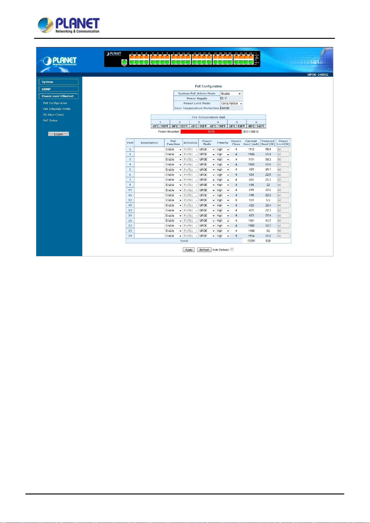
4.5.1 PoE Configuration
This section provid es PoE (Power over Ether net) C onf igur at i on and PoE ou tput status of Ultra PoE Managed Injector Hub
as screen in Figur e 4-5-2 appears. T able 4-5-2 describes the PoE Configuration object of Ultr a PoE Managed Injector Hub.
• System PoE Admin Mode
• Power Supply
• Power Limit Mode
• Over Temperature
Protection
• PoE Temperature Unit 1
• PoE Temperature Unit 2
• PoE Temperature Unit 3
Figure 4-5-2: PoE Configuration Web Page Screen
Allows user to disable / enable PoE function.
Displays PoE power supply status.
Allows user to configure power limit mode, which can be cho s en.
Consumption: Based on the real device power consumption where PoE power is
delivered as system default setting is in this mode.
Allocation: Users allow to assign how much P oE power to each port and the system
will reserve PoE power to PD.
Prevent system from being too hot that may cause damage. When PoE unit
temperature rises over the temperature threshold value, PoE power budget will be
reduced.
Displays the current operating temperature of PoE chip unit 1.
Displays the current operating temperature of PoE chip unit 2.
Displays the current operating temperature of PoE chip unit 3. (UPOE-1600G only)
• PoE Temperature Unit 4
• PoE Temperature Unit 5
• PoE Temperature Unit 6
Displays the current operating temperature of PoE chip unit 4. (UPOE-1600G only)
Displays the current operating temperature of PoE chip unit 5. (UPOE-2400G only)
Displays the current operating temperature of PoE chip unit 6. (UPOE-2400G only)
47
Page 48

per word, like ‘, “, \, < and >.
Allows user to disable or enable per port PoE function, also allow choose schedule
Indicates the scheduled profile mode. Possible profil es are:
Allows user to select IEEE80 2.3at/80 2.3af/Ultra P oE compati bility mode. T he defau lt
(pair #1 in both T568A and T568B) form one side of
(pair #1 in both T568A and T568B) form one side of the
8 (pair #4 in both T568A and T568B) provide the
The Priority represents PoE ports priority. There are three levels of power priority
is over the total power
overload is detected, the port will auto shut down and keep in detection mode until
Check this box to refresh the page automatically. Automatic refresh occurs every 3
User’s Manual of UPOE-800G/UPOE-1600G/UPOE-2400G
• Power Allocation
• Description
• PoE Function
• Schedule
• Power Mode
Displays the current total power consumption status.
This function provides input per port description and the available letters is 30.
NOTE: The total max imum letters are only 800. Some of special wor ds will count as 5
for enable PoE Schedule function of each port.
Profile1
Profile2
Profile3
Profile4
This function is available when choosing schedule on each port.
value is UPOE mode.
Indicates the power inline mode. Possible profiles are:
Midspan: Pins 4–5
the DC supply and pins 7–8 (pair # 4 in both T56 8A and T568 B) provide t he
return
Endspan: Pins 1–2 (pair #2 in both T568A and T568B) form one side of
the DC supply and pins 3–6 (pair #3 in both T56 8A and T568 B) provide t he
return
UPOE: Pins 1–2 (pair #2 in both T568A and T568B) form one side of the
DC supply and pins 3–6 (pair #3 in both T568A and T568B) provide the
return. Pins 4–5
DC supply and pins 7–
return
named Low, High and Critical.
• Priority
• Device Class
• Current Used [mA]
• Power Used [W]
• Power Limit [W]
• Apply
• Refresh
• Auto-Refresh
The priority is used in case the total power consumption
budget. In this c ase the port w ith the low est priority w ill be turned off, an d offer pow er
for the port of higher priority.
Displays PoE class level.
The IEEE 802.3af standard offers PoE class level from 1 to 3 and IEEE 802.3at
standard offers the class from 1 to 4.
The Power Used shows how much current the PD currently is using.
The Power Used shows how much power the PD currently is using
It can limit the port PoE supply watts. Per port maximum value must be less than 60
watts. Total port values must be less than th e Power Reservat ion value. Once pow er
PD’s power consumption is lower than the power limit value.
Press this button to take effect.
Press this button to refresh the current Web page.
seconds.
Table 4-5-2: Descriptions of the PoE Configuration Objects Screen
48
Page 49

User’s Manual of UPOE-800G/UPOE-1600G/UPOE-2400G
4.5.2 PoE Schedule Profile
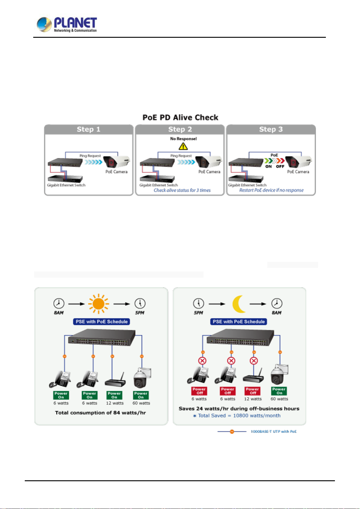
This section provides user to configure PoE schedule and scheduled power recycling. The “PoE schedule” helps you to
enable or disable PoE power feedin g for PoE ports duri ng specified time inter vals and it is a pow erful function to help SM Bs
or enterprises save power and money.
Scheduled Power Recycling
The Ultra PoE Managed Injector Hub allows each of the connected PoE IP cameras to reboot at a specified time each
week. Therefore, it will reduce the chance of IP camera crash resulting from buffer overflow.
49
Page 50

Object
Description
Allows user to disable or enable per port PoE function, also allow choose
Indicates the scheduled profile mode. Possible profil es are:
button
Check this box to refresh the page automatically. Automatic refresh occurs every
User’s Manual of UPOE-800G/UPOE-1600G/UPOE-2400G
The PoE Schedule Profile Web Screens are shown in Figure 4-5-3 and Table 4-5-3.
Figure 4-5-3: PoE Configuration Web Page Screen
The page includes the following information:
• PoE Function
• Schedule
•
• button
• Auto-Refresh
Table 4-5-3: Descriptions of the per port PoE Schedule Profile Objects Screen
schedule for enable PoE Schedule function of each port.
This function available when choose schedule on each port.
Saves the current configuration.
Refreshes the Web page and the current configuration if user doesn’t save it.
3 seconds.
Profile1
Profile2
Profile3
Profile4
50
Page 51

Object
Description
Set the schedule profile mode. Possible profiles are:
Profile4
User’s Manual of UPOE-800G/UPOE-1600G/UPOE-2400G
PoE Schedule user can configure a duration time for PoE port as default value does not provide power; screen in Figure
4-5-4 and Table 4-5-4 show.
Figure 4-5-4: PoE Schedule Web Page Screen
The page includes the following information:
• Profile
• Delete
• Week Day
Profile1
Profile2
Profile3
Check to delete the entry.
Allows user to set week day for defining PoE function by enabling it on the day.
Sun.: Sunday
Mon.: Monday
Tue.: Tuesday
Wed.: Wednesday
Thu.: Thursday
Fri.: Friday
Sat.: Saturday
51
Page 52

Allows user to enable or disable the whole PoE port reboot by PoE reboot
User’s Manual of UPOE-800G/UPOE-1600G/UPOE-2400G
• Start Hour
• Start Min
• End Hour
• End Min
• Reboot Enable
• Reboot Only
• Reboot Hour
• Reboot Min
Allows user to set what hour PoE function does by enabling it.
Allows user to set what minute PoE function does by enabling it.
Allows user to set what hour PoE function does by disabling it.
Allows user to set what minute PoE function does by disabling it.
schedule. Please note that if y ou w ant PoE sched ule and Po E reboot s chedule t o
work at the same time, please use this function, and don’t use Reboot Only
function. This function offers administrator to reboot PoE device at an indicated
time if administrator has this kind of requirement.
Allows user to reboot PoE function by PoE reboot schedule. Please note that if
administrator enables this function, PoE schedule will not set time to profile. This
function is just for PoE port to reset at an indicated time.
Allows user to set what hour PoE reboots. This function is only for PoE reboot
schedule.
Allows user to set what minute PoE reboots. This function is only for PoE reboot
schedule.
Table 4-5-4: Descriptions of the PoE Schedule Configuration Objects Screen
Buttons
: Click to add new rule.
: Click to apply changes
: Check to delete the entry.
52
Page 53

User’s Manual of UPOE-800G/UPOE-1600G/UPOE-2400G
4.5.3 PoE Alive Check Configuration
The Ultra PoE Manage d Inject or Hub can be configured t o monitor conn ected PD’s status in real-time via ping action. Once
the PD stops working a nd without response, the Ultra PoE Managed Injector Hub are going to restart PoE port power, and
bring the PD back to work. It will greatly enhance the reliability and reduces administrator management burden.
This page provides you with how to configure PD Alive Check as the screen in Figure 4-5-5 appears.
Figure 4-5-5: PD Alive Check Configuration Screenshot
53
Page 54

Object
Description
• Mode
Allows user to enable or disable per port PD Alive Check function. All ports are
• Remote PD IP Address
This column allow s use r t o set PoE device IP address here fo r sy ste m ma kin g p ing
• Interval Time (10~300s)
This column allows user to set how long system should issue a ping request to PD
for detecting whether P D i s a li v e or de ad. I nt erv al time range is fro m 1 0 sec ond s t o
• Retry Count (1~5)
This column allows user to set how many times system wants to retry ping to PD.
• Action
Allows user to set which action will be apply if the PD is without any response. The
It means system will reset the PoE port that is connected to the
Alarm: It means system will issue an alarm message via Syslog..
• Reboot Time (30~180s)
This column allow s user to set the P oE device reboot ing time. As there are so many
The page includes the following fields:
User’s Manual of UPOE-800G/UPOE-1600G/UPOE-2400G
disabled as default value.
to the PoE device. Please note that the PD’s IP address must be set to the same
network segment as the Ultra PoE Managed Injector Hub.
300 seconds.
For example, if we set count 2, the meaning is that if system retry ping to the PD
and the PD doesn’t response continuously, the PoE port will be reset.
Ultra PoE Managed Injector Hub offers 3 actions as follows:
PD Reboot:
PD.
PD Reboot & Alarm: It means system will reset the PoE port and issue an
alarm message via Syslog,
Buttons
kinds of PoE devices on the market, they have different rebooting times.
The PD Alive-check is not a defining standard, so the PoE device on the market
doesn’t report reboots done inf ormat ion to th e Ultra P oE M anaged I nje ctor Hub. So
user has to make sure how long the PD will be finished to boot, and then set the
time value to this column.
System is going to check the PD again according to the reboot time. If you cannot
make sure precise booting time, we suggest you set it longer.
: Click to apply changes
: Refreshes the Web page and the current configuration if user doesn’t save it.
54
Page 55

Object
Description
• Port Number
Displays per port status.
• Watt
Displays per port PoE usage.
Indicates the end-span PoE operation mode of that port.
Indicates the mid-span PoE operation mode of that port.
Indicates the ultra PoE operation mode of that port.
User’s Manual of UPOE-800G/UPOE-1600G/UPOE-2400G
4.5.4 PoE Status
This page allows user to see the usage of individual PoE Port. The screen in Figure 4-5-6 appears
The page includes the following fields:
•
•
•
Buttons
: Check this box to refresh the page automatically. Automatic refresh occurs every 3 seconds.
: Refreshes the Web page and the current configuration.
Figure 4-5-6: PoE Status Screenshot
54
Page 56

User’s Manual of UPOE-800G/UPOE-1600G/UPOE-2400G
5. POWER OVER ETHERNET OVERVIEW
What is PoE?
Based on the global standard IEEE 802.3af, PoE is a technology for wired Ethernet, the most widely installed local area
network technology adopted today. PoE allows the electrical power necessary for the operation of each end-device to be
carried by data cables ra ther th an by separat e power cor ds. New network applicati ons, such as IP Camera s, VoIP Phon es,
and Wireless Networking, can help enterprises improve productivity. It minimizes wires that must be used to install the
network for offering lower cost, and less power failures.
IEEE802.3af, also called Data Terminal equipment (DTE) power via Media dependent interface (MDI), is an international
standard to define the tra nsmission for power over Ether net. The IEEE 802.3af also defines t wo types of sour ce equipment:
Mid-Span and End-Span.
Mid-Span
Mid-Span device is placed between legacy switch and the powered device. Mid-Span taps the unused wire pairs 4/5 and
7/8 to carry power; the other four are for data transmission
End-Span
End-Span device is directly connected with power device. End-Span could also tap the wire 1/2 and 3/6.
PoE system architecture
The specification of PoE typically requires two devices: the Powered Source Equipment (PSE) and the Powered Device
(PD). The PSE is either an End-Span or a M id-Span, while the PD is a PoE-enabled terminal, such as IP Phones, Wireless
LAN, etc. Power can be delivered over data pairs or spare pairs of standard CAT-5e cabling.
How power is transferred through the cable
A standard Cat5e Ethernet cable has four twisted pairs, but only two of these are used for 10BASE-T, 100BASE-T and
1000BASE-T. The specification allows two options for using these cables for power as shown in Figure 5-1-1 and Figure
5-1-2.
The spare pairs are u sed. Figu re 5-1-1 shows the pair on pins 4 and 5 are connected togethe r and for m the po sitive supp ly,
and the pair on pins 7 and 8 are connected and form the negative supply. (In fact, a late change to the spec allows either
polarity to be used).
55
Page 57

User’s Manual of UPOE-800G/UPOE-1600G/UPOE-2400G
Figure 5-1-1 - Power Supplied over the Spare Pins
The data pairs are used. S in ce Ether net pairs are transformer coup led at ea ch e nd, it i s po s sibl e to apply DC power to th e
center tap of the i solatio n trans former w ithout ups etting the data tr ansf er. I n this mode of ope ration the pa ir o n pin s 3 and 6
and the pair on pins 1 and 2 can be of either polarity.
Figure 5-1-2 - Power Supplied over the Data Pins
When to install PoE?
Consider the following scenarios:
• You're planning to i nstall the latest VoIP Phone syste m to minimize cabling bui lding costs w hen your comp any moves int o
new office next month.
• The company staff has bee n clamor ing f or a w ireless acce ss po int in t he pic nic area be hind the buildi ng so t hey ca n w ork
on their laptops through lunch, but the cost of electrical power to the outside is not affordable.
• Management asks for IP Surveillance Cameras and business access systems throughout the facility, but they would
rather avoid another electrician's payment.
56
Page 58

Volts specified
Measure whether powered device has the
correct signature resistance of 15–33 kΩ
Measure which power level class the
resistor indicates
Startup
Where the powered device will start up
>42
>37.2
>38
User’s Manual of UPOE-800G/UPOE-1600G/UPOE-2400G
6. THE POE PROVISION PROCESS
While adding PoE support to networked devices is relatively painless, it should be realized that power cannot simply be
transferred over existing Cat5e cables. Without proper preparation, doing so may result in damage to devices that are not
designed to support provision of power over their network interfaces.
The PSE is the manager of t he PoE process. At the beginning, only sm all v oltag e level is induced on t he port's output till a
valid PD is detected during the Detection period. The PSE m ay choose to per f or m clas sif ic ation to estimate the amount of
power to be consumed by this PD. After a ti me-controlle d start-up, the PSE beg ins supplying the 52V DC level to the PD till
it is physically or electrically disconnected. Upon disconnection, voltage and power shut down.
Since the PSE is responsible for the PoE proc es s tim ing, it is the one generating the probing sign als pr ior to o perating the
PD and monitoring the various scenarios that may occur during operation.
All probing is done using voltage induction and current measurement in return.
Stages of powering up a PoE link
Stage Action
Detection
Classification
Normal operation
Supply power to device 44-57 50-57 25.0–60.0
802.3af 802.3at
2.7-10.0 1.8–10.0
14.5-20.5 12.5–25.5
Volts managed
by chipset
6.1 Line Detection
Before power is applied, safety dictates that it must first be ensured that a valid PD is connected to the PSE's output. This
process is referred to as "line detection", and involves the PSE seeking a specific, 25 KΩ signature resistor. Detection of
this signature indicates that a valid PD is connected, and that provision of power to the device may commence.
The signature resistor lies in the PD's PoE front-end, isolated from the rest of the PD's circuitries till detection is certified.
6.2 Classification
Once a PD is detected, the PS E may optiona lly perform cla ssification, to d etermine the max imal power a PD is to consume .
The PSE induces 15.5-25.5V DC, limited to 600 mA, for a period of 10 to 75 ms responded by a certain current
consumption by the PD, indicating its power class.
The PD is assigned to one of 5 classes: 0 (default class) indicates that full 15.4 watts should be provided, 1-3 indicate
various required power levels and 4 is instead of reserved has a power range of 12.95 – 25.5 watts. PDs that support
classification are assi gne d to class 0. Special c are must be employed in the definition of class thr es hol ds, as cl as sifi cat ion
may be affected by cable losses.
Classifying a PD according to its power consumption may assist a PoE system in optimizing its power distribution. Such a
system typically suffers from lack of power resources, so that efficient power management based on classification results
may reduce total system costs.
57
Page 59

User’s Manual of UPOE-800G/UPOE-1600G/UPOE-2400G
6.3 Start-up
Once line detection and optional classification stages are completed, the PSE must switch from low voltage to its full
voltage capacity (44-57 Volts) over a minimal amount of time (above 15 microseconds).
A gradual startup is required, as a sudden rise in voltage (reaching high frequencies) would introduce noise on the data
lines.
Once provision of power is init iated, it is common for inrush current t o be experienced at t he PSE port, due to th e PD’s input
capacitance. A PD must be de signed to cease inr ush current consum ption (of over 350 mA / 600mA) within 50 ms of pow er
provision startup.
6.4 Operation
During normal operation, the PSE provides 44-57 VDC, able to support a minimum of 15.4watt / 25.5-watt power.
Power Overloads
The IEEE 802.3af / IEEE 802. 3at stand ar d defi nes han dli ng of overload conditions. In the event of an overload (a PD
drawing a higher power level than the allowed 12.95 watts / 25.5 watts), or an outright short circuit caused by a failure in
cabling or in the PD, the PSE must shut down power within 50 to 75 milliseconds, while limiting current drain during this
period to protect the cabling infrastructure. Immediate voltage drop is avoided to prevent shutdown due to random
fluctuations.
6.5 Power Disconnection Scenarios
The IEEE 802.3af / IEEE 802.3at stand ard requir es t hat dev ices powered over Ethernet be disconnecte d safe ly ( i.e. pow er
needs to be shut down within a short period of time following disconnection of a PD from an active port).
When a PD is disconnected, there is a danger that it will be replaced by a non-PoE-ready device while power is still on.
Imagine disconnecting a powered IP phone utilizing 52 VDC, and then inadvertently plugging the powered Ethernet cable
into a non-PoE notebook computer. What’s sure to follow is not a pretty picture.
The standard defines two means of disconnection, DC Disconnect and AC Disconnect, both of which provide the same
functionality - the PSE shutdowns power to a disconnected port within 300 to 400ms. The upper boundary is a physical
human limit for disconnecting one PD and reconnecting another.
DC Disconnect
DC Disconnect detection involves measurement of current. Naturally, a disconnected PD stops consuming current, which
can be inspected by the PSE. The PSE must therefore disconnect power within 300 to 400 ms from the current flow stop.
The lower time boundary is important to prevent shutdown due to random fluctuations.
AC Disconnect
This method is based on the fa ct t hat when a v alid PD i s connecte d to a port , th e AC impeda nce me asured on its ter mina ls
is significantly lower than in the case of an open port (disconnected PD).
AC Disconnect detect ion inv ol v es the in du ctio n of low AC signal in add itio n to the 52 VDC operating v ol tage. The returne d
AC signal amplitude is monitored by the PSE at the port terminals. During normal operation, the PD's relatively low
impedance lowers the returned AC signal while a sudden disconnection of this PD will cause a surge to the full AC signal
level and will indicate PD disconnection.
58
Page 60

Classification Period
Operation Period
User’s Manual of UPOE-800G/UPOE-1600G/UPOE-2400G
APPENDIX A
A.1 MDI Settings
The Medium-Dependent In terf ace (M DI or R J45) serv es as t he dat a/power interfac e betw een E thernet e lement s. As such,
it has two optional connection methods to carry the power. N amed Alternat ive A & B, T able 1 details the two pow er feeding
alternatives.
Pin Alternative A Alternative B
1 Vport Negative
2 Vport Negative
3 Vport Positive
4 Vpo rt Posi t ive
5 Vpo rt Posi t ive
6 Vport Positive
7 Vport Negative
8 Vport Negative
Table -1 Alternative Table
Delivering power through an RJ45 connector’s center tap (“Phantom Feeding”) guarantees that bi-directional data flow is
maintained, regardless of a module’s pow er status.
A.2 Power Device Classification Values
Class PD Current –
[mA]
0 0 – 4 0.44 – 12.95 Default
1 9 – 12 0.44 – 3.84 Optional
PD Power –
Note
[W]
2 17 -20 3.84 – 6.49 Optional
3 26 – 30 6.49 – 12.95 Optional
4 36 - 44 12.95 - 25 Optional
59
Page 61

User’s Manual of UPOE-800G/UPOE-1600G/UPOE-2400G
A.3 DATA OUT PoE Injector RJ45 Port Pin Assignments
PIN NO 10BASE-T
1
2
3
4
5
6
7
8
100BASE-TX
TX+ DC- DA+ DC-
TX- DC- DA- DC-
RX+ DC+ DB+ DC+
- DC+ DC+ DC+
- DC+ DC- DC+
RX- DC+ DB- DC+
- DC- DD+ DC-
- DC0 DD- DC0
1000BASE-T
A.4 RJ45 Pin Assignment of Non-802.3af/802.3at Standard PD with PoE
Mid-span PD
Pin out of Cisco non-802.3af standard PD Pin out of POE Mid-span
PIN NO SIGNAL
1 RX+
2 RX3 TX+
4 VCC5 VCC6 TX7 VCC+
8 VCC+
PIN NO SIGNAL
1 RX+
2 RX3 TX+
4 VCC5 VCC6 TX7 VCC+
8 VCC+
Before you power PD, please check whether the RJ45 connector pin assignment follows IEEE 802.3af/IEEE 802.3at
standard; otherwise, you may need to change o ne of th e RJ45 conn ector pin as signments, w hich is attach ed with the UT P
cable.
60
 Loading...